affirma nc verilog simulator help - university of virginia...
TRANSCRIPT

Affirma™ NC Verilog Simulator Help
Product Version 3.1June 2000
1995-2000 Cadence Design Systems, Inc. All rights reserved.Printed in the United States of America.
Cadence Design Systems, Inc., 555 River Oaks Parkway, San Jose, CA 95134, USA
Trademarks: Trademarks and service marks of Cadence Design Systems, Inc. (Cadence) contained in thisdocument are attributed to Cadence with the appropriate symbol. For queries regarding Cadence’s trademarks,contact the corporate legal department at the address shown above or call 1-800-862-4522.
All other trademarks are the property of their respective holders.
Restricted Print Permission: This publication is protected by copyright and any unauthorized use of thispublication may violate copyright, trademark, and other laws. Except as specified in this permission statement,this publication may not be copied, reproduced, modified, published, uploaded, posted, transmitted, ordistributed in any way, without prior written permission from Cadence. This statement grants you permission toprint one (1) hard copy of this publication subject to the following conditions:
1. The publication may be used solely for personal, informational, and noncommercial purposes;2. The publication may not be modified in any way;3. Any copy of the publication or portion thereof must include all original copyright, trademark, and other
proprietary notices and this permission statement; and4. Cadence reserves the right to revoke this authorization at any time, and any such use shall be
discontinued immediately upon written notice from Cadence.
Disclaimer: Information in this publication is subject to change without notice and does not represent acommitment on the part of Cadence. The information contained herein is the proprietary and confidentialinformation of Cadence or its licensors, and is supplied subject to, and may be used only by Cadence’s customerin accordance with, a written agreement between Cadence and its customer. Except as may be explicitly setforth in such agreement, Cadence does not make, and expressly disclaims, any representations or warrantiesas to the completeness, accuracy or usefulness of the information contained in this document. Cadence doesnot warrant that use of such information will not infringe any third party rights, nor does Cadence assume anyliability for damages or costs of any kind that may result from use of such information.
Restricted Rights: Use, duplication, or disclosure by the Government is subject to restrictions as set forth inFAR52.227-14 and DFAR252.227-7013 et seq. or its successor.

Affirma NC Verilog Simulator Help
Contents
1
Over view of the Affirma™ NC V erilog Sim ulator . . . . . . . . . . . . . . . . . . . . . . . . . . . 23
Native Compiled Code . . . . . . . . . . . . . . . . . . . . . . . . . . . . . . . . . . . . . . . . . . . . . . . . . . . 23The Interleaved Native Compiled Code (INCA) Architecture . . . . . . . . . . . . . . . . . . . . . . 24The Cadence® Verilog Desktop Simulator . . . . . . . . . . . . . . . . . . . . . . . . . . . . . . . . . . . 26Language Support . . . . . . . . . . . . . . . . . . . . . . . . . . . . . . . . . . . . . . . . . . . . . . . . . . . . . . 27Memory Requirements . . . . . . . . . . . . . . . . . . . . . . . . . . . . . . . . . . . . . . . . . . . . . . . . . . 27Setting Up Your Design Environment . . . . . . . . . . . . . . . . . . . . . . . . . . . . . . . . . . . . . . . . 28Running the NC Verilog Simulator . . . . . . . . . . . . . . . . . . . . . . . . . . . . . . . . . . . . . . . . . . 29
Single-Step Invocation With ncverilog . . . . . . . . . . . . . . . . . . . . . . . . . . . . . . . . . . . . 34Multi-Step Invocation (Library-Based Mode) . . . . . . . . . . . . . . . . . . . . . . . . . . . . . . . 35
Simulator Library Databases . . . . . . . . . . . . . . . . . . . . . . . . . . . . . . . . . . . . . . . . . . . . . . 35
2
Getting Help . . . . . . . . . . . . . . . . . . . . . . . . . . . . . . . . . . . . . . . . . . . . . . . . . . . . . . . . . . . 38
About Online Help . . . . . . . . . . . . . . . . . . . . . . . . . . . . . . . . . . . . . . . . . . . . . . . . . . . . . . 38Invoking the Documentation System . . . . . . . . . . . . . . . . . . . . . . . . . . . . . . . . . . . . . 39Printing Documents . . . . . . . . . . . . . . . . . . . . . . . . . . . . . . . . . . . . . . . . . . . . . . . . . . 40Searching Documents . . . . . . . . . . . . . . . . . . . . . . . . . . . . . . . . . . . . . . . . . . . . . . . . 40
Getting Help on Commands to Run Tools . . . . . . . . . . . . . . . . . . . . . . . . . . . . . . . . . . . . 40Getting Help on Simulator Commands . . . . . . . . . . . . . . . . . . . . . . . . . . . . . . . . . . . . . . 41Getting Help on Tool Messages . . . . . . . . . . . . . . . . . . . . . . . . . . . . . . . . . . . . . . . . . . . . 41Related Manuals and Specifications . . . . . . . . . . . . . . . . . . . . . . . . . . . . . . . . . . . . . . . . 42
Verilog . . . . . . . . . . . . . . . . . . . . . . . . . . . . . . . . . . . . . . . . . . . . . . . . . . . . . . . . . . . . 42VHDL . . . . . . . . . . . . . . . . . . . . . . . . . . . . . . . . . . . . . . . . . . . . . . . . . . . . . . . . . . . . . 43
June 2000 2 Product Version 3.1

Affirma NC Verilog Simulator Help
3
Using NCLaunc h . . . . . . . . . . . . . . . . . . . . . . . . . . . . . . . . . . . . . . . . . . . . . . . . . . . . . . . 44
4
Running NC V erilog With the ncverilog Command . . . . . . . . . . . . . . . . . . . . . . . . . 46
Overview . . . . . . . . . . . . . . . . . . . . . . . . . . . . . . . . . . . . . . . . . . . . . . . . . . . . . . . . . . . . . 47How ncverilog Works . . . . . . . . . . . . . . . . . . . . . . . . . . . . . . . . . . . . . . . . . . . . . . . . . . . . 49ncverilog Command Syntax . . . . . . . . . . . . . . . . . . . . . . . . . . . . . . . . . . . . . . . . . . . . . . . 51ncverilog Command Options . . . . . . . . . . . . . . . . . . . . . . . . . . . . . . . . . . . . . . . . . . . . . . 52Plus Options for NC Verilog Tools . . . . . . . . . . . . . . . . . . . . . . . . . . . . . . . . . . . . . . . . . . 60Verilog-XL Command-Line Options Translation . . . . . . . . . . . . . . . . . . . . . . . . . . . . . . . . 64
Verilog-XL Dash (-) Option Translation Table . . . . . . . . . . . . . . . . . . . . . . . . . . . . . . . 64Verilog-XL Plus (+) Option Translation Table . . . . . . . . . . . . . . . . . . . . . . . . . . . . . . . 66
Example ncverilog Run . . . . . . . . . . . . . . . . . . . . . . . . . . . . . . . . . . . . . . . . . . . . . . . . . . 69Mapping of Warning Messages . . . . . . . . . . . . . . . . . . . . . . . . . . . . . . . . . . . . . . . . . . . . 71Updating Design Changes . . . . . . . . . . . . . . . . . . . . . . . . . . . . . . . . . . . . . . . . . . . . . . . . 72Using +ncuid+ to Run in Regression Mode . . . . . . . . . . . . . . . . . . . . . . . . . . . . . . . . . . . 73Using -R and -r to Simulate a Snapshot . . . . . . . . . . . . . . . . . . . . . . . . . . . . . . . . . . . . . 75
Using -R to Simulate a Snapshot Multiple Times . . . . . . . . . . . . . . . . . . . . . . . . . . . . 75Using -r to Simulate a Saved Snapshot . . . . . . . . . . . . . . . . . . . . . . . . . . . . . . . . . . . 77
PLI Tasks . . . . . . . . . . . . . . . . . . . . . . . . . . . . . . . . . . . . . . . . . . . . . . . . . . . . . . . . . . . . . 79SDF Annotation . . . . . . . . . . . . . . . . . . . . . . . . . . . . . . . . . . . . . . . . . . . . . . . . . . . . . . . . 79
Using $test$plusargs to Selectively Perform Annotations . . . . . . . . . . . . . . . . . . . . . 81Specifying Precision . . . . . . . . . . . . . . . . . . . . . . . . . . . . . . . . . . . . . . . . . . . . . . . . . . 81Turning Off SDF Annotation . . . . . . . . . . . . . . . . . . . . . . . . . . . . . . . . . . . . . . . . . . . . 81Using the +sdf_cmd_file+ Option . . . . . . . . . . . . . . . . . . . . . . . . . . . . . . . . . . . . . . . . 82Controlling SDF Annotator Output . . . . . . . . . . . . . . . . . . . . . . . . . . . . . . . . . . . . . . . 82
Troubleshooting . . . . . . . . . . . . . . . . . . . . . . . . . . . . . . . . . . . . . . . . . . . . . . . . . . . . . . . . 83
5
Modeling Y our Har dware . . . . . . . . . . . . . . . . . . . . . . . . . . . . . . . . . . . . . . . . . . . . . . . . 84
Arrays of Instances . . . . . . . . . . . . . . . . . . . . . . . . . . . . . . . . . . . . . . . . . . . . . . . . . . . . . 86Instance Array Names . . . . . . . . . . . . . . . . . . . . . . . . . . . . . . . . . . . . . . . . . . . . . . . . 86Array Range Expressions . . . . . . . . . . . . . . . . . . . . . . . . . . . . . . . . . . . . . . . . . . . . . . 87
June 2000 3 Product Version 3.1

Affirma NC Verilog Simulator Help
Port Connections . . . . . . . . . . . . . . . . . . . . . . . . . . . . . . . . . . . . . . . . . . . . . . . . . . . . 87Ports of Instance Arrays . . . . . . . . . . . . . . . . . . . . . . . . . . . . . . . . . . . . . . . . . . . . . . . 88Differing Instances in an Array . . . . . . . . . . . . . . . . . . . . . . . . . . . . . . . . . . . . . . . . . . 89Hierarchical References . . . . . . . . . . . . . . . . . . . . . . . . . . . . . . . . . . . . . . . . . . . . . . . 89NC Verilog Restrictions to the IEEE Standard . . . . . . . . . . . . . . . . . . . . . . . . . . . . . . 90Arrays of Instances and Tcl Commands . . . . . . . . . . . . . . . . . . . . . . . . . . . . . . . . . . . 93
6
Setting Up Y our En vir onment . . . . . . . . . . . . . . . . . . . . . . . . . . . . . . . . . . . . . . . . . . . . 94
Overview . . . . . . . . . . . . . . . . . . . . . . . . . . . . . . . . . . . . . . . . . . . . . . . . . . . . . . . . . . . . . 95The Library.Cell:View Approach . . . . . . . . . . . . . . . . . . . . . . . . . . . . . . . . . . . . . . . . . . . . 96The cds.lib File . . . . . . . . . . . . . . . . . . . . . . . . . . . . . . . . . . . . . . . . . . . . . . . . . . . . . . . . . 97
The Work Library . . . . . . . . . . . . . . . . . . . . . . . . . . . . . . . . . . . . . . . . . . . . . . . . . . . . 98cds.lib Statements . . . . . . . . . . . . . . . . . . . . . . . . . . . . . . . . . . . . . . . . . . . . . . . . . . . 98cds.lib Syntax Rules . . . . . . . . . . . . . . . . . . . . . . . . . . . . . . . . . . . . . . . . . . . . . . . . . 100Example cds.lib File . . . . . . . . . . . . . . . . . . . . . . . . . . . . . . . . . . . . . . . . . . . . . . . . . 101Binding One Library to Multiple Directories . . . . . . . . . . . . . . . . . . . . . . . . . . . . . . . 101Directory Binding Rules . . . . . . . . . . . . . . . . . . . . . . . . . . . . . . . . . . . . . . . . . . . . . . 102Debugging cds.lib Files . . . . . . . . . . . . . . . . . . . . . . . . . . . . . . . . . . . . . . . . . . . . . . 102
The hdl.var File . . . . . . . . . . . . . . . . . . . . . . . . . . . . . . . . . . . . . . . . . . . . . . . . . . . . . . . 104hdl.var Statements . . . . . . . . . . . . . . . . . . . . . . . . . . . . . . . . . . . . . . . . . . . . . . . . . . 105hdl.var Variables . . . . . . . . . . . . . . . . . . . . . . . . . . . . . . . . . . . . . . . . . . . . . . . . . . . . 106hdl.var Syntax Rules . . . . . . . . . . . . . . . . . . . . . . . . . . . . . . . . . . . . . . . . . . . . . . . . . 111Example hdl.var File . . . . . . . . . . . . . . . . . . . . . . . . . . . . . . . . . . . . . . . . . . . . . . . . . 113Debugging hdl.var Files . . . . . . . . . . . . . . . . . . . . . . . . . . . . . . . . . . . . . . . . . . . . . . 114
The setup.loc File . . . . . . . . . . . . . . . . . . . . . . . . . . . . . . . . . . . . . . . . . . . . . . . . . . . . . . 115setup.loc Syntax Rules . . . . . . . . . . . . . . . . . . . . . . . . . . . . . . . . . . . . . . . . . . . . . . . 116
June 2000 4 Product Version 3.1

Affirma NC Verilog Simulator Help
Directory Structure Example . . . . . . . . . . . . . . . . . . . . . . . . . . . . . . . . . . . . . . . . . . . . . 117
7
Compiling V erilog Sour ce Files With ncvlog . . . . . . . . . . . . . . . . . . . . . . . . . . . . . . 121
Overview . . . . . . . . . . . . . . . . . . . . . . . . . . . . . . . . . . . . . . . . . . . . . . . . . . . . . . . . . . . . 122ncvlog Command Syntax . . . . . . . . . . . . . . . . . . . . . . . . . . . . . . . . . . . . . . . . . . . . . . . . 124ncvlog Command Options . . . . . . . . . . . . . . . . . . . . . . . . . . . . . . . . . . . . . . . . . . . . . . . 125Example ncvlog Command Lines . . . . . . . . . . . . . . . . . . . . . . . . . . . . . . . . . . . . . . . . . 139hdl.var Variables . . . . . . . . . . . . . . . . . . . . . . . . . . . . . . . . . . . . . . . . . . . . . . . . . . . . . . 141Conditionally Compiling Source Code . . . . . . . . . . . . . . . . . . . . . . . . . . . . . . . . . . . . . . 144Controlling the Compilation of Design Units into Library.Cell:View . . . . . . . . . . . . . . . . 146
The Default . . . . . . . . . . . . . . . . . . . . . . . . . . . . . . . . . . . . . . . . . . . . . . . . . . . . . . . . 146The LIB_MAP and VIEW_MAP Variables . . . . . . . . . . . . . . . . . . . . . . . . . . . . . . . . 148The WORK and VIEW Variables . . . . . . . . . . . . . . . . . . . . . . . . . . . . . . . . . . . . . . . 150The -work and -view Options . . . . . . . . . . . . . . . . . . . . . . . . . . . . . . . . . . . . . . . . . . 152The -specificunit Option . . . . . . . . . . . . . . . . . . . . . . . . . . . . . . . . . . . . . . . . . . . . . . 153The `worklib and `view Compiler Directives . . . . . . . . . . . . . . . . . . . . . . . . . . . . . . . 154Mapping of Modules Defined Within `include Files . . . . . . . . . . . . . . . . . . . . . . . . . 156
Defining Macros on the Command Line . . . . . . . . . . . . . . . . . . . . . . . . . . . . . . . . . . . . 159
8
Elaborating the Design With ncelab . . . . . . . . . . . . . . . . . . . . . . . . . . . . . . . . . . . . . 161
Overview . . . . . . . . . . . . . . . . . . . . . . . . . . . . . . . . . . . . . . . . . . . . . . . . . . . . . . . . . . . . 162ncelab Command Syntax . . . . . . . . . . . . . . . . . . . . . . . . . . . . . . . . . . . . . . . . . . . . . . . . 166
General Options . . . . . . . . . . . . . . . . . . . . . . . . . . . . . . . . . . . . . . . . . . . . . . . . . . . . 166VHDL Only Options . . . . . . . . . . . . . . . . . . . . . . . . . . . . . . . . . . . . . . . . . . . . . . . . . 167Verilog Only Options . . . . . . . . . . . . . . . . . . . . . . . . . . . . . . . . . . . . . . . . . . . . . . . . . 167
ncelab Command Options . . . . . . . . . . . . . . . . . . . . . . . . . . . . . . . . . . . . . . . . . . . . . . . 169Example ncelab Command Lines . . . . . . . . . . . . . . . . . . . . . . . . . . . . . . . . . . . . . . . . . 195hdl.var Variables . . . . . . . . . . . . . . . . . . . . . . . . . . . . . . . . . . . . . . . . . . . . . . . . . . . . . . 196How Modules and UDPs Are Resolved During Elaboration . . . . . . . . . . . . . . . . . . . . . 197
The Default Binding Mechanism . . . . . . . . . . . . . . . . . . . . . . . . . . . . . . . . . . . . . . . . 198The -binding Option . . . . . . . . . . . . . . . . . . . . . . . . . . . . . . . . . . . . . . . . . . . . . . . . . 203The ‘uselib Compiler Directive . . . . . . . . . . . . . . . . . . . . . . . . . . . . . . . . . . . . . . . . . 206
June 2000 5 Product Version 3.1

Affirma NC Verilog Simulator Help
Enabling Read, Write, or Connectivity Access to Simulation Objects . . . . . . . . . . . . . . 211Regression Mode and Tcl Commands . . . . . . . . . . . . . . . . . . . . . . . . . . . . . . . . . . . 212Regression Mode and PLI Applications . . . . . . . . . . . . . . . . . . . . . . . . . . . . . . . . . . 212Regression Mode and the SimVision Debug Environment . . . . . . . . . . . . . . . . . . . . 214Using -access to Specify Read/Write/Connectivity Access . . . . . . . . . . . . . . . . . . . 215Using -afile to Include an Access File . . . . . . . . . . . . . . . . . . . . . . . . . . . . . . . . . . . 216Generating an Access File . . . . . . . . . . . . . . . . . . . . . . . . . . . . . . . . . . . . . . . . . . . . 221Guidelines for Access Control . . . . . . . . . . . . . . . . . . . . . . . . . . . . . . . . . . . . . . . . . 222
Selecting a Delay Mode . . . . . . . . . . . . . . . . . . . . . . . . . . . . . . . . . . . . . . . . . . . . . . . . . 228Delay Modes . . . . . . . . . . . . . . . . . . . . . . . . . . . . . . . . . . . . . . . . . . . . . . . . . . . . . . . 228Reasons to Select a Delay Mode . . . . . . . . . . . . . . . . . . . . . . . . . . . . . . . . . . . . . . . 230Setting a Delay Mode . . . . . . . . . . . . . . . . . . . . . . . . . . . . . . . . . . . . . . . . . . . . . . . . 230Timescales and Simulation Time Units . . . . . . . . . . . . . . . . . . . . . . . . . . . . . . . . . . 231Overriding Delay Values . . . . . . . . . . . . . . . . . . . . . . . . . . . . . . . . . . . . . . . . . . . . . . 233Delay Mode Example . . . . . . . . . . . . . . . . . . . . . . . . . . . . . . . . . . . . . . . . . . . . . . . . 235Decompiling with Delay Modes . . . . . . . . . . . . . . . . . . . . . . . . . . . . . . . . . . . . . . . . 236Macro Module Expansion and Delay Modes . . . . . . . . . . . . . . . . . . . . . . . . . . . . . . 236Summary of Delay Mode Rules . . . . . . . . . . . . . . . . . . . . . . . . . . . . . . . . . . . . . . . . 237
Setting Pulse Controls . . . . . . . . . . . . . . . . . . . . . . . . . . . . . . . . . . . . . . . . . . . . . . . . . . 238Overview . . . . . . . . . . . . . . . . . . . . . . . . . . . . . . . . . . . . . . . . . . . . . . . . . . . . . . . . . 238Global Pulse Control . . . . . . . . . . . . . . . . . . . . . . . . . . . . . . . . . . . . . . . . . . . . . . . . 239Pulse Control for Specific Modules and Module Paths . . . . . . . . . . . . . . . . . . . . . . . 241Pulse Filtering Style . . . . . . . . . . . . . . . . . . . . . . . . . . . . . . . . . . . . . . . . . . . . . . . . . 243
9
Simulating Y our Design With ncsim . . . . . . . . . . . . . . . . . . . . . . . . . . . . . . . . . . . . . 254
Overview . . . . . . . . . . . . . . . . . . . . . . . . . . . . . . . . . . . . . . . . . . . . . . . . . . . . . . . . . . . . 255ncsim Command Syntax . . . . . . . . . . . . . . . . . . . . . . . . . . . . . . . . . . . . . . . . . . . . . . . . 257ncsim Command Options . . . . . . . . . . . . . . . . . . . . . . . . . . . . . . . . . . . . . . . . . . . . . . . 258Example ncsim Command Lines . . . . . . . . . . . . . . . . . . . . . . . . . . . . . . . . . . . . . . . . . . 273hdl.var Variables . . . . . . . . . . . . . . . . . . . . . . . . . . . . . . . . . . . . . . . . . . . . . . . . . . . . . . 274Invoking the Simulator . . . . . . . . . . . . . . . . . . . . . . . . . . . . . . . . . . . . . . . . . . . . . . . . . . 275
Invoking the Simulator in Noninteractive Mode . . . . . . . . . . . . . . . . . . . . . . . . . . . . 276Invoking the Simulator in Interactive Mode . . . . . . . . . . . . . . . . . . . . . . . . . . . . . . . . 277
June 2000 6 Product Version 3.1

Affirma NC Verilog Simulator Help
Starting a Simulation . . . . . . . . . . . . . . . . . . . . . . . . . . . . . . . . . . . . . . . . . . . . . . . . . . . 278Saving, Restarting, Resetting, and Reinvoking a Simulation . . . . . . . . . . . . . . . . . . . . . 280
Saving and Restarting the Simulation . . . . . . . . . . . . . . . . . . . . . . . . . . . . . . . . . . . 280Resetting the Simulation . . . . . . . . . . . . . . . . . . . . . . . . . . . . . . . . . . . . . . . . . . . . . 282Reinvoking a Simulation . . . . . . . . . . . . . . . . . . . . . . . . . . . . . . . . . . . . . . . . . . . . . . 282
Updating Design Changes When You Invoke the Simulator . . . . . . . . . . . . . . . . . . . . . 284Providing Interactive Commands from a File . . . . . . . . . . . . . . . . . . . . . . . . . . . . . . . . . 287
-input Command Syntax . . . . . . . . . . . . . . . . . . . . . . . . . . . . . . . . . . . . . . . . . . . . . . 288Exiting the Simulation . . . . . . . . . . . . . . . . . . . . . . . . . . . . . . . . . . . . . . . . . . . . . . . . . . 290
10
Mixed Verilog/VHDL Sim ulation . . . . . . . . . . . . . . . . . . . . . . . . . . . . . . . . . . . . . . . . . 291
Mapping of Data Types . . . . . . . . . . . . . . . . . . . . . . . . . . . . . . . . . . . . . . . . . . . . . . . . . 292Model Import With or Without a Model Shell . . . . . . . . . . . . . . . . . . . . . . . . . . . . . . . . . 294Importing Verilog Into VHDL . . . . . . . . . . . . . . . . . . . . . . . . . . . . . . . . . . . . . . . . . . . . . 295
Importing Verilog Into VHDL Without a Shell . . . . . . . . . . . . . . . . . . . . . . . . . . . . . . 296Importing Verilog Into VHDL With a Shell . . . . . . . . . . . . . . . . . . . . . . . . . . . . . . . . . 299
Importing VHDL Into Verilog . . . . . . . . . . . . . . . . . . . . . . . . . . . . . . . . . . . . . . . . . . . . . 301Importing VHDL Into Verilog Without a Shell . . . . . . . . . . . . . . . . . . . . . . . . . . . . . . 301Importing VHDL Into Verilog With a Shell . . . . . . . . . . . . . . . . . . . . . . . . . . . . . . . . . 303Importing VHDL Into Verilog With ncverilog . . . . . . . . . . . . . . . . . . . . . . . . . . . . . . . 305
A Verilog-VHDL-Verilog Example . . . . . . . . . . . . . . . . . . . . . . . . . . . . . . . . . . . . . . . . . . 306Preparing the Design Without Shells . . . . . . . . . . . . . . . . . . . . . . . . . . . . . . . . . . . . 306Preparing the Design With Shells . . . . . . . . . . . . . . . . . . . . . . . . . . . . . . . . . . . . . . . 309
Generating a Shell with ncshell . . . . . . . . . . . . . . . . . . . . . . . . . . . . . . . . . . . . . . . . . . . 311ncshell Command Syntax . . . . . . . . . . . . . . . . . . . . . . . . . . . . . . . . . . . . . . . . . . . . . 311ncshell Command Options . . . . . . . . . . . . . . . . . . . . . . . . . . . . . . . . . . . . . . . . . . . . 313
Importing a Verilog-XL Design into VHDL . . . . . . . . . . . . . . . . . . . . . . . . . . . . . . . . . . . 319Preparing a Leapfrog Verilog Model Import Design . . . . . . . . . . . . . . . . . . . . . . . . . . . . 325
The ncxlimport Utility . . . . . . . . . . . . . . . . . . . . . . . . . . . . . . . . . . . . . . . . . . . . . . . . 325ncxlimport Syntax . . . . . . . . . . . . . . . . . . . . . . . . . . . . . . . . . . . . . . . . . . . . . . . . . . . 326ncxlimport Command Options . . . . . . . . . . . . . . . . . . . . . . . . . . . . . . . . . . . . . . . . . 326
June 2000 7 Product Version 3.1

Affirma NC Verilog Simulator Help
Mixed_Language Out-of_Module References . . . . . . . . . . . . . . . . . . . . . . . . . . . . . . . . 331Path Names and Mixed-Language Designs . . . . . . . . . . . . . . . . . . . . . . . . . . . . . . . . . 334SDF Annotation for Mixed-Language Designs . . . . . . . . . . . . . . . . . . . . . . . . . . . . . . . . 336
11
Debugging Y our Design . . . . . . . . . . . . . . . . . . . . . . . . . . . . . . . . . . . . . . . . . . . . . . . . 337
Managing Databases . . . . . . . . . . . . . . . . . . . . . . . . . . . . . . . . . . . . . . . . . . . . . . . . . . . 339Opening a Database . . . . . . . . . . . . . . . . . . . . . . . . . . . . . . . . . . . . . . . . . . . . . . . . 339Displaying Information About Databases . . . . . . . . . . . . . . . . . . . . . . . . . . . . . . . . . 340Disabling a Database . . . . . . . . . . . . . . . . . . . . . . . . . . . . . . . . . . . . . . . . . . . . . . . . 340Enabling a Database . . . . . . . . . . . . . . . . . . . . . . . . . . . . . . . . . . . . . . . . . . . . . . . . 340Closing a Database . . . . . . . . . . . . . . . . . . . . . . . . . . . . . . . . . . . . . . . . . . . . . . . . . 341
Setting and Deleting Probes . . . . . . . . . . . . . . . . . . . . . . . . . . . . . . . . . . . . . . . . . . . . . 342Setting a Probe . . . . . . . . . . . . . . . . . . . . . . . . . . . . . . . . . . . . . . . . . . . . . . . . . . . . . 342Displaying Information About Probes . . . . . . . . . . . . . . . . . . . . . . . . . . . . . . . . . . . . 343Disabling a Probe . . . . . . . . . . . . . . . . . . . . . . . . . . . . . . . . . . . . . . . . . . . . . . . . . . . 343Enabling a Probe . . . . . . . . . . . . . . . . . . . . . . . . . . . . . . . . . . . . . . . . . . . . . . . . . . . 344Deleting a Probe . . . . . . . . . . . . . . . . . . . . . . . . . . . . . . . . . . . . . . . . . . . . . . . . . . . . 344
Traversing the Model Hierarchy . . . . . . . . . . . . . . . . . . . . . . . . . . . . . . . . . . . . . . . . . . . 345Path Names . . . . . . . . . . . . . . . . . . . . . . . . . . . . . . . . . . . . . . . . . . . . . . . . . . . . . . . 345Setting the Debug Scope . . . . . . . . . . . . . . . . . . . . . . . . . . . . . . . . . . . . . . . . . . . . . 345
Setting Breakpoints . . . . . . . . . . . . . . . . . . . . . . . . . . . . . . . . . . . . . . . . . . . . . . . . . . . . 347Setting a Condition Breakpoint . . . . . . . . . . . . . . . . . . . . . . . . . . . . . . . . . . . . . . . . . 348Setting a Source Code Line Breakpoint . . . . . . . . . . . . . . . . . . . . . . . . . . . . . . . . . . 349Setting an Object Breakpoint . . . . . . . . . . . . . . . . . . . . . . . . . . . . . . . . . . . . . . . . . . 350Setting a Time Breakpoint . . . . . . . . . . . . . . . . . . . . . . . . . . . . . . . . . . . . . . . . . . . . 351Setting a Delta Breakpoint . . . . . . . . . . . . . . . . . . . . . . . . . . . . . . . . . . . . . . . . . . . . 352Setting a Process Breakpoint . . . . . . . . . . . . . . . . . . . . . . . . . . . . . . . . . . . . . . . . . . 352Setting a Subprogram Breakpoint . . . . . . . . . . . . . . . . . . . . . . . . . . . . . . . . . . . . . . 353
June 2000 8 Product Version 3.1

Affirma NC Verilog Simulator Help
Disabling, Enabling, Deleting, and Displaying Breakpoints . . . . . . . . . . . . . . . . . . . . . . 354Stepping Through Lines of Code . . . . . . . . . . . . . . . . . . . . . . . . . . . . . . . . . . . . . . . . . . 355Forcing and Releasing Signal Values . . . . . . . . . . . . . . . . . . . . . . . . . . . . . . . . . . . . . . 356Depositing Values to Signals . . . . . . . . . . . . . . . . . . . . . . . . . . . . . . . . . . . . . . . . . . . . . 357Displaying Information About Simulation Objects . . . . . . . . . . . . . . . . . . . . . . . . . . . . . 358Displaying the Drivers of Signals . . . . . . . . . . . . . . . . . . . . . . . . . . . . . . . . . . . . . . . . . . 358Displaying Waveforms with Signalscan waves . . . . . . . . . . . . . . . . . . . . . . . . . . . . . . . . 359
Creating a Database and Probing Signals . . . . . . . . . . . . . . . . . . . . . . . . . . . . . . . . 359Opening a Database with $shm_open . . . . . . . . . . . . . . . . . . . . . . . . . . . . . . . . . . . 360Probing Signals with $shm_probe . . . . . . . . . . . . . . . . . . . . . . . . . . . . . . . . . . . . . . 361Invoking Signalscan waves . . . . . . . . . . . . . . . . . . . . . . . . . . . . . . . . . . . . . . . . . . . . 363Using the Register Window . . . . . . . . . . . . . . . . . . . . . . . . . . . . . . . . . . . . . . . . . . . 364Converting SHM Databases to the Current Format . . . . . . . . . . . . . . . . . . . . . . . . . 365
Comparing Databases with Comparescan . . . . . . . . . . . . . . . . . . . . . . . . . . . . . . . . . . 367Converting Older SHM Databases to the Current Format . . . . . . . . . . . . . . . . . . . . 367
Displaying Debug Settings . . . . . . . . . . . . . . . . . . . . . . . . . . . . . . . . . . . . . . . . . . . . . . . 369Setting a Default Radix . . . . . . . . . . . . . . . . . . . . . . . . . . . . . . . . . . . . . . . . . . . . . . . . . 369Setting Variables . . . . . . . . . . . . . . . . . . . . . . . . . . . . . . . . . . . . . . . . . . . . . . . . . . . . . . 370Suppressing Assert Messages in IEEE or User-Defined Packages . . . . . . . . . . . . . . . 375Editing a Source File . . . . . . . . . . . . . . . . . . . . . . . . . . . . . . . . . . . . . . . . . . . . . . . . . . . 377Searching for a Line Number in the Source Code . . . . . . . . . . . . . . . . . . . . . . . . . . . . . 378Searching for a Text String in the Source Code . . . . . . . . . . . . . . . . . . . . . . . . . . . . . . . 378Configuring Your Simulation Environment . . . . . . . . . . . . . . . . . . . . . . . . . . . . . . . . . . . 378Saving and Restoring Your Simulation Environment . . . . . . . . . . . . . . . . . . . . . . . . . . . 379Creating or Deleting an Alias . . . . . . . . . . . . . . . . . . . . . . . . . . . . . . . . . . . . . . . . . . . . . 380Getting a History of Commands . . . . . . . . . . . . . . . . . . . . . . . . . . . . . . . . . . . . . . . . . . . 380Managing Custom Buttons . . . . . . . . . . . . . . . . . . . . . . . . . . . . . . . . . . . . . . . . . . . . . . 381
12
Using the Tc l Command-Line Interface . . . . . . . . . . . . . . . . . . . . . . . . . . . . . . . . . . 382
Overview . . . . . . . . . . . . . . . . . . . . . . . . . . . . . . . . . . . . . . . . . . . . . . . . . . . . . . . . . . . . 382Executing UNIX Commands . . . . . . . . . . . . . . . . . . . . . . . . . . . . . . . . . . . . . . . . . . . 383Command Description Conventions . . . . . . . . . . . . . . . . . . . . . . . . . . . . . . . . . . . . . 384
alias . . . . . . . . . . . . . . . . . . . . . . . . . . . . . . . . . . . . . . . . . . . . . . . . . . . . . . . . . . . . . . . . 386alias Command Syntax . . . . . . . . . . . . . . . . . . . . . . . . . . . . . . . . . . . . . . . . . . . . . . 386
June 2000 9 Product Version 3.1

Affirma NC Verilog Simulator Help
alias Command Modifiers and Options . . . . . . . . . . . . . . . . . . . . . . . . . . . . . . . . . . 386alias Command Examples . . . . . . . . . . . . . . . . . . . . . . . . . . . . . . . . . . . . . . . . . . . . 387
attribute . . . . . . . . . . . . . . . . . . . . . . . . . . . . . . . . . . . . . . . . . . . . . . . . . . . . . . . . . . . . . 388attribute Command Syntax . . . . . . . . . . . . . . . . . . . . . . . . . . . . . . . . . . . . . . . . . . . . 388attribute Command Options and Modifiers . . . . . . . . . . . . . . . . . . . . . . . . . . . . . . . . 389attribute Command Examples . . . . . . . . . . . . . . . . . . . . . . . . . . . . . . . . . . . . . . . . . 389
call . . . . . . . . . . . . . . . . . . . . . . . . . . . . . . . . . . . . . . . . . . . . . . . . . . . . . . . . . . . . . . . . . 392call Command Syntax . . . . . . . . . . . . . . . . . . . . . . . . . . . . . . . . . . . . . . . . . . . . . . . 392call Command Modifiers and Options . . . . . . . . . . . . . . . . . . . . . . . . . . . . . . . . . . . 394call Command Examples . . . . . . . . . . . . . . . . . . . . . . . . . . . . . . . . . . . . . . . . . . . . . 395
coverage . . . . . . . . . . . . . . . . . . . . . . . . . . . . . . . . . . . . . . . . . . . . . . . . . . . . . . . . . . . . 396coverage Command Syntax . . . . . . . . . . . . . . . . . . . . . . . . . . . . . . . . . . . . . . . . . . . 397coverage Command Modifiers and Options . . . . . . . . . . . . . . . . . . . . . . . . . . . . . . . 397coverage Command Examples . . . . . . . . . . . . . . . . . . . . . . . . . . . . . . . . . . . . . . . . 398
database . . . . . . . . . . . . . . . . . . . . . . . . . . . . . . . . . . . . . . . . . . . . . . . . . . . . . . . . . . . . 401database Command Syntax . . . . . . . . . . . . . . . . . . . . . . . . . . . . . . . . . . . . . . . . . . . 402database Command Modifiers and Options . . . . . . . . . . . . . . . . . . . . . . . . . . . . . . . 403Opening a Database . . . . . . . . . . . . . . . . . . . . . . . . . . . . . . . . . . . . . . . . . . . . . . . . 403Closing a Database . . . . . . . . . . . . . . . . . . . . . . . . . . . . . . . . . . . . . . . . . . . . . . . . . 406Disabling a Database . . . . . . . . . . . . . . . . . . . . . . . . . . . . . . . . . . . . . . . . . . . . . . . . 406Enabling a Database . . . . . . . . . . . . . . . . . . . . . . . . . . . . . . . . . . . . . . . . . . . . . . . . 406Displaying Information about Databases . . . . . . . . . . . . . . . . . . . . . . . . . . . . . . . . . 406database Command Examples . . . . . . . . . . . . . . . . . . . . . . . . . . . . . . . . . . . . . . . . 406
deposit . . . . . . . . . . . . . . . . . . . . . . . . . . . . . . . . . . . . . . . . . . . . . . . . . . . . . . . . . . . . . . 409deposit Command Syntax . . . . . . . . . . . . . . . . . . . . . . . . . . . . . . . . . . . . . . . . . . . . 410deposit Command Modifiers and Options . . . . . . . . . . . . . . . . . . . . . . . . . . . . . . . . 410deposit Command Examples . . . . . . . . . . . . . . . . . . . . . . . . . . . . . . . . . . . . . . . . . . 411
describe . . . . . . . . . . . . . . . . . . . . . . . . . . . . . . . . . . . . . . . . . . . . . . . . . . . . . . . . . . . . . 413describe Command Syntax . . . . . . . . . . . . . . . . . . . . . . . . . . . . . . . . . . . . . . . . . . . 413describe Command Modifiers and Options . . . . . . . . . . . . . . . . . . . . . . . . . . . . . . . 413describe Command Examples . . . . . . . . . . . . . . . . . . . . . . . . . . . . . . . . . . . . . . . . . 413
drivers . . . . . . . . . . . . . . . . . . . . . . . . . . . . . . . . . . . . . . . . . . . . . . . . . . . . . . . . . . . . . . 417drivers Command Syntax . . . . . . . . . . . . . . . . . . . . . . . . . . . . . . . . . . . . . . . . . . . . . 417drivers Command Modifiers and Options . . . . . . . . . . . . . . . . . . . . . . . . . . . . . . . . . 417drivers Command Report Format . . . . . . . . . . . . . . . . . . . . . . . . . . . . . . . . . . . . . . . 418drivers Command Examples . . . . . . . . . . . . . . . . . . . . . . . . . . . . . . . . . . . . . . . . . . 422
June 2000 10 Product Version 3.1

Affirma NC Verilog Simulator Help
exit . . . . . . . . . . . . . . . . . . . . . . . . . . . . . . . . . . . . . . . . . . . . . . . . . . . . . . . . . . . . . . . . . 428exit Command Syntax . . . . . . . . . . . . . . . . . . . . . . . . . . . . . . . . . . . . . . . . . . . . . . . 428exit Command Modifiers and Options . . . . . . . . . . . . . . . . . . . . . . . . . . . . . . . . . . . 428exit Command Examples . . . . . . . . . . . . . . . . . . . . . . . . . . . . . . . . . . . . . . . . . . . . . 428
finish . . . . . . . . . . . . . . . . . . . . . . . . . . . . . . . . . . . . . . . . . . . . . . . . . . . . . . . . . . . . . . . 429finish Command Syntax . . . . . . . . . . . . . . . . . . . . . . . . . . . . . . . . . . . . . . . . . . . . . . 429finish Command Modifiers and Options . . . . . . . . . . . . . . . . . . . . . . . . . . . . . . . . . . 429finish Command Examples . . . . . . . . . . . . . . . . . . . . . . . . . . . . . . . . . . . . . . . . . . . . 429
fmibkpt . . . . . . . . . . . . . . . . . . . . . . . . . . . . . . . . . . . . . . . . . . . . . . . . . . . . . . . . . . . . . . 430fmibkpt Command Syntax . . . . . . . . . . . . . . . . . . . . . . . . . . . . . . . . . . . . . . . . . . . . 430fmibkpt Command Modifiers and Options . . . . . . . . . . . . . . . . . . . . . . . . . . . . . . . . 430
force . . . . . . . . . . . . . . . . . . . . . . . . . . . . . . . . . . . . . . . . . . . . . . . . . . . . . . . . . . . . . . . . 431force Command Syntax . . . . . . . . . . . . . . . . . . . . . . . . . . . . . . . . . . . . . . . . . . . . . . 432force Command Modifiers and Options . . . . . . . . . . . . . . . . . . . . . . . . . . . . . . . . . . 432force Command Examples . . . . . . . . . . . . . . . . . . . . . . . . . . . . . . . . . . . . . . . . . . . . 432
help . . . . . . . . . . . . . . . . . . . . . . . . . . . . . . . . . . . . . . . . . . . . . . . . . . . . . . . . . . . . . . . . 434help Command Syntax . . . . . . . . . . . . . . . . . . . . . . . . . . . . . . . . . . . . . . . . . . . . . . . 434help Command Modifiers and Options . . . . . . . . . . . . . . . . . . . . . . . . . . . . . . . . . . . 435help Command Examples . . . . . . . . . . . . . . . . . . . . . . . . . . . . . . . . . . . . . . . . . . . . 435
history . . . . . . . . . . . . . . . . . . . . . . . . . . . . . . . . . . . . . . . . . . . . . . . . . . . . . . . . . . . . . . 437history Command Syntax . . . . . . . . . . . . . . . . . . . . . . . . . . . . . . . . . . . . . . . . . . . . . 437history Command Options . . . . . . . . . . . . . . . . . . . . . . . . . . . . . . . . . . . . . . . . . . . . 437history Command Examples . . . . . . . . . . . . . . . . . . . . . . . . . . . . . . . . . . . . . . . . . . 438
input . . . . . . . . . . . . . . . . . . . . . . . . . . . . . . . . . . . . . . . . . . . . . . . . . . . . . . . . . . . . . . . . 440input Command Syntax . . . . . . . . . . . . . . . . . . . . . . . . . . . . . . . . . . . . . . . . . . . . . . 441input Command Modifiers and Options . . . . . . . . . . . . . . . . . . . . . . . . . . . . . . . . . . 441input Command Examples . . . . . . . . . . . . . . . . . . . . . . . . . . . . . . . . . . . . . . . . . . . . 441
memory . . . . . . . . . . . . . . . . . . . . . . . . . . . . . . . . . . . . . . . . . . . . . . . . . . . . . . . . . . . . . 443memory Command Syntax . . . . . . . . . . . . . . . . . . . . . . . . . . . . . . . . . . . . . . . . . . . . 445memory Command Modifiers and Options . . . . . . . . . . . . . . . . . . . . . . . . . . . . . . . . 445Loading VHDL Memory . . . . . . . . . . . . . . . . . . . . . . . . . . . . . . . . . . . . . . . . . . . . . . 445Dumping VHDL Memory . . . . . . . . . . . . . . . . . . . . . . . . . . . . . . . . . . . . . . . . . . . . . 446memory Command Examples . . . . . . . . . . . . . . . . . . . . . . . . . . . . . . . . . . . . . . . . . 446
omi . . . . . . . . . . . . . . . . . . . . . . . . . . . . . . . . . . . . . . . . . . . . . . . . . . . . . . . . . . . . . . . . . 448omi Command Syntax . . . . . . . . . . . . . . . . . . . . . . . . . . . . . . . . . . . . . . . . . . . . . . . 448omi Command Modifiers and Options . . . . . . . . . . . . . . . . . . . . . . . . . . . . . . . . . . . 449
June 2000 11 Product Version 3.1

Affirma NC Verilog Simulator Help
Displaying Information . . . . . . . . . . . . . . . . . . . . . . . . . . . . . . . . . . . . . . . . . . . . . . . 449Issuing Commands . . . . . . . . . . . . . . . . . . . . . . . . . . . . . . . . . . . . . . . . . . . . . . . . . . 449omi Command Examples . . . . . . . . . . . . . . . . . . . . . . . . . . . . . . . . . . . . . . . . . . . . . 450
probe . . . . . . . . . . . . . . . . . . . . . . . . . . . . . . . . . . . . . . . . . . . . . . . . . . . . . . . . . . . . . . . 451probe Command Syntax . . . . . . . . . . . . . . . . . . . . . . . . . . . . . . . . . . . . . . . . . . . . . . 453probe Command Modifiers and Options . . . . . . . . . . . . . . . . . . . . . . . . . . . . . . . . . . 454Creating a Probe . . . . . . . . . . . . . . . . . . . . . . . . . . . . . . . . . . . . . . . . . . . . . . . . . . . 454Deleting a Probe . . . . . . . . . . . . . . . . . . . . . . . . . . . . . . . . . . . . . . . . . . . . . . . . . . . . 459Disabling a Probe . . . . . . . . . . . . . . . . . . . . . . . . . . . . . . . . . . . . . . . . . . . . . . . . . . . 459Enabling a Probe . . . . . . . . . . . . . . . . . . . . . . . . . . . . . . . . . . . . . . . . . . . . . . . . . . . 460Saving a Script to Recreate Probes . . . . . . . . . . . . . . . . . . . . . . . . . . . . . . . . . . . . . 460Displaying Information About Probes . . . . . . . . . . . . . . . . . . . . . . . . . . . . . . . . . . . . 460probe Command Examples . . . . . . . . . . . . . . . . . . . . . . . . . . . . . . . . . . . . . . . . . . . 461
process . . . . . . . . . . . . . . . . . . . . . . . . . . . . . . . . . . . . . . . . . . . . . . . . . . . . . . . . . . . . . 466process Command Syntax . . . . . . . . . . . . . . . . . . . . . . . . . . . . . . . . . . . . . . . . . . . . 466process Command Modifiers and Options . . . . . . . . . . . . . . . . . . . . . . . . . . . . . . . . 467process Command Examples . . . . . . . . . . . . . . . . . . . . . . . . . . . . . . . . . . . . . . . . . 468
release . . . . . . . . . . . . . . . . . . . . . . . . . . . . . . . . . . . . . . . . . . . . . . . . . . . . . . . . . . . . . . 471release Command Syntax . . . . . . . . . . . . . . . . . . . . . . . . . . . . . . . . . . . . . . . . . . . . 471release Command Modifiers and Options . . . . . . . . . . . . . . . . . . . . . . . . . . . . . . . . 472
release Command Examples . . . . . . . . . . . . . . . . . . . . . . . . . . . . . . . . . . . . . . . . . . 472reset . . . . . . . . . . . . . . . . . . . . . . . . . . . . . . . . . . . . . . . . . . . . . . . . . . . . . . . . . . . . . . . . 473
reset Command Syntax . . . . . . . . . . . . . . . . . . . . . . . . . . . . . . . . . . . . . . . . . . . . . . 473reset Command Modifiers and Options . . . . . . . . . . . . . . . . . . . . . . . . . . . . . . . . . . 473reset Command Examples . . . . . . . . . . . . . . . . . . . . . . . . . . . . . . . . . . . . . . . . . . . . 473
restart . . . . . . . . . . . . . . . . . . . . . . . . . . . . . . . . . . . . . . . . . . . . . . . . . . . . . . . . . . . . . . 474restart Command Syntax . . . . . . . . . . . . . . . . . . . . . . . . . . . . . . . . . . . . . . . . . . . . . 475restart Command Modifiers and Options . . . . . . . . . . . . . . . . . . . . . . . . . . . . . . . . . 475restart Command Examples . . . . . . . . . . . . . . . . . . . . . . . . . . . . . . . . . . . . . . . . . . . 475
run . . . . . . . . . . . . . . . . . . . . . . . . . . . . . . . . . . . . . . . . . . . . . . . . . . . . . . . . . . . . . . . . . 477run Command Syntax . . . . . . . . . . . . . . . . . . . . . . . . . . . . . . . . . . . . . . . . . . . . . . . . 477run Command Modifiers and Options . . . . . . . . . . . . . . . . . . . . . . . . . . . . . . . . . . . . 478run Command Examples . . . . . . . . . . . . . . . . . . . . . . . . . . . . . . . . . . . . . . . . . . . . . 479
save . . . . . . . . . . . . . . . . . . . . . . . . . . . . . . . . . . . . . . . . . . . . . . . . . . . . . . . . . . . . . . . . 481save Command Syntax . . . . . . . . . . . . . . . . . . . . . . . . . . . . . . . . . . . . . . . . . . . . . . 482
June 2000 12 Product Version 3.1

Affirma NC Verilog Simulator Help
save Command Modifiers and Options . . . . . . . . . . . . . . . . . . . . . . . . . . . . . . . . . . 483save Command Examples . . . . . . . . . . . . . . . . . . . . . . . . . . . . . . . . . . . . . . . . . . . . 483
scope . . . . . . . . . . . . . . . . . . . . . . . . . . . . . . . . . . . . . . . . . . . . . . . . . . . . . . . . . . . . . . . 487scope Command Syntax . . . . . . . . . . . . . . . . . . . . . . . . . . . . . . . . . . . . . . . . . . . . . 487scope Command Modifiers and Options . . . . . . . . . . . . . . . . . . . . . . . . . . . . . . . . . 488scope Command Examples . . . . . . . . . . . . . . . . . . . . . . . . . . . . . . . . . . . . . . . . . . . 490
source . . . . . . . . . . . . . . . . . . . . . . . . . . . . . . . . . . . . . . . . . . . . . . . . . . . . . . . . . . . . . . 495source Command Syntax . . . . . . . . . . . . . . . . . . . . . . . . . . . . . . . . . . . . . . . . . . . . . 495source Command Modifiers and Options . . . . . . . . . . . . . . . . . . . . . . . . . . . . . . . . . 495source Command Examples . . . . . . . . . . . . . . . . . . . . . . . . . . . . . . . . . . . . . . . . . . 496
stack . . . . . . . . . . . . . . . . . . . . . . . . . . . . . . . . . . . . . . . . . . . . . . . . . . . . . . . . . . . . . . . 497stack Command Syntax . . . . . . . . . . . . . . . . . . . . . . . . . . . . . . . . . . . . . . . . . . . . . . 497stack Command Modifiers and Options . . . . . . . . . . . . . . . . . . . . . . . . . . . . . . . . . . 497stack Command Examples . . . . . . . . . . . . . . . . . . . . . . . . . . . . . . . . . . . . . . . . . . . . 498
status . . . . . . . . . . . . . . . . . . . . . . . . . . . . . . . . . . . . . . . . . . . . . . . . . . . . . . . . . . . . . . . 502status Command Syntax . . . . . . . . . . . . . . . . . . . . . . . . . . . . . . . . . . . . . . . . . . . . . 502status Command Modifiers and Options . . . . . . . . . . . . . . . . . . . . . . . . . . . . . . . . . 502status Command Examples . . . . . . . . . . . . . . . . . . . . . . . . . . . . . . . . . . . . . . . . . . . 502
stop . . . . . . . . . . . . . . . . . . . . . . . . . . . . . . . . . . . . . . . . . . . . . . . . . . . . . . . . . . . . . . . . 503stop Command Syntax . . . . . . . . . . . . . . . . . . . . . . . . . . . . . . . . . . . . . . . . . . . . . . . 504stop Command Modifiers and Options . . . . . . . . . . . . . . . . . . . . . . . . . . . . . . . . . . . 505Creating a Breakpoint . . . . . . . . . . . . . . . . . . . . . . . . . . . . . . . . . . . . . . . . . . . . . . . . 505Deleting a Breakpoint . . . . . . . . . . . . . . . . . . . . . . . . . . . . . . . . . . . . . . . . . . . . . . . . 510Disabling a Breakpoint . . . . . . . . . . . . . . . . . . . . . . . . . . . . . . . . . . . . . . . . . . . . . . . 510Enabling a Breakpoint . . . . . . . . . . . . . . . . . . . . . . . . . . . . . . . . . . . . . . . . . . . . . . . 510Displaying Information About Breakpoints . . . . . . . . . . . . . . . . . . . . . . . . . . . . . . . . 510stop Command Examples . . . . . . . . . . . . . . . . . . . . . . . . . . . . . . . . . . . . . . . . . . . . 511Tcl Expressions as Arguments . . . . . . . . . . . . . . . . . . . . . . . . . . . . . . . . . . . . . . . . . 518
strobe . . . . . . . . . . . . . . . . . . . . . . . . . . . . . . . . . . . . . . . . . . . . . . . . . . . . . . . . . . . . . . . 521strobe Command Syntax . . . . . . . . . . . . . . . . . . . . . . . . . . . . . . . . . . . . . . . . . . . . . 522strobe Command Modifiers and Options . . . . . . . . . . . . . . . . . . . . . . . . . . . . . . . . . 522strobe Command Examples . . . . . . . . . . . . . . . . . . . . . . . . . . . . . . . . . . . . . . . . . . . 523
task . . . . . . . . . . . . . . . . . . . . . . . . . . . . . . . . . . . . . . . . . . . . . . . . . . . . . . . . . . . . . . . . 528task Command Syntax . . . . . . . . . . . . . . . . . . . . . . . . . . . . . . . . . . . . . . . . . . . . . . . 528task Command Modifiers and Options . . . . . . . . . . . . . . . . . . . . . . . . . . . . . . . . . . . 529task Command Examples . . . . . . . . . . . . . . . . . . . . . . . . . . . . . . . . . . . . . . . . . . . . 529
June 2000 13 Product Version 3.1

Affirma NC Verilog Simulator Help
time . . . . . . . . . . . . . . . . . . . . . . . . . . . . . . . . . . . . . . . . . . . . . . . . . . . . . . . . . . . . . . . . 532time Command Syntax . . . . . . . . . . . . . . . . . . . . . . . . . . . . . . . . . . . . . . . . . . . . . . . 532time Command Modifiers and Options . . . . . . . . . . . . . . . . . . . . . . . . . . . . . . . . . . . 533time Command Examples . . . . . . . . . . . . . . . . . . . . . . . . . . . . . . . . . . . . . . . . . . . . 533
value . . . . . . . . . . . . . . . . . . . . . . . . . . . . . . . . . . . . . . . . . . . . . . . . . . . . . . . . . . . . . . . 535value Command Syntax . . . . . . . . . . . . . . . . . . . . . . . . . . . . . . . . . . . . . . . . . . . . . . 535value Command Modifiers and Options . . . . . . . . . . . . . . . . . . . . . . . . . . . . . . . . . . 536value Command Examples . . . . . . . . . . . . . . . . . . . . . . . . . . . . . . . . . . . . . . . . . . . . 536
version . . . . . . . . . . . . . . . . . . . . . . . . . . . . . . . . . . . . . . . . . . . . . . . . . . . . . . . . . . . . . . 539version Command Syntax . . . . . . . . . . . . . . . . . . . . . . . . . . . . . . . . . . . . . . . . . . . . 539version Command Modifiers and Options . . . . . . . . . . . . . . . . . . . . . . . . . . . . . . . . 539version Command Examples . . . . . . . . . . . . . . . . . . . . . . . . . . . . . . . . . . . . . . . . . . 539
where . . . . . . . . . . . . . . . . . . . . . . . . . . . . . . . . . . . . . . . . . . . . . . . . . . . . . . . . . . . . . . . 540where Command Syntax . . . . . . . . . . . . . . . . . . . . . . . . . . . . . . . . . . . . . . . . . . . . . 540where Command Modifiers and Options . . . . . . . . . . . . . . . . . . . . . . . . . . . . . . . . . 540where Command Examples . . . . . . . . . . . . . . . . . . . . . . . . . . . . . . . . . . . . . . . . . . . 540
Verilog-XL and NC Verilog Simulator Interactive Debug Commands . . . . . . . . . . . . . . . 541
13
Using the Affirma™ SimVision Anal ysis En vir onment . . . . . . . . . . . . . . . . . . . . . 547
14
Timing Chec ks . . . . . . . . . . . . . . . . . . . . . . . . . . . . . . . . . . . . . . . . . . . . . . . . . . . . . . . . 549
Overview . . . . . . . . . . . . . . . . . . . . . . . . . . . . . . . . . . . . . . . . . . . . . . . . . . . . . . . . . . . . 550Timing Check System Tasks . . . . . . . . . . . . . . . . . . . . . . . . . . . . . . . . . . . . . . . . . . . . . 551
$setup . . . . . . . . . . . . . . . . . . . . . . . . . . . . . . . . . . . . . . . . . . . . . . . . . . . . . . . . . . . . 551$hold . . . . . . . . . . . . . . . . . . . . . . . . . . . . . . . . . . . . . . . . . . . . . . . . . . . . . . . . . . . . . 552$setuphold . . . . . . . . . . . . . . . . . . . . . . . . . . . . . . . . . . . . . . . . . . . . . . . . . . . . . . . . 553$width . . . . . . . . . . . . . . . . . . . . . . . . . . . . . . . . . . . . . . . . . . . . . . . . . . . . . . . . . . . . 557$period . . . . . . . . . . . . . . . . . . . . . . . . . . . . . . . . . . . . . . . . . . . . . . . . . . . . . . . . . . . 559$skew . . . . . . . . . . . . . . . . . . . . . . . . . . . . . . . . . . . . . . . . . . . . . . . . . . . . . . . . . . . . 561$recovery . . . . . . . . . . . . . . . . . . . . . . . . . . . . . . . . . . . . . . . . . . . . . . . . . . . . . . . . . 562$removal . . . . . . . . . . . . . . . . . . . . . . . . . . . . . . . . . . . . . . . . . . . . . . . . . . . . . . . . . . 563$recrem . . . . . . . . . . . . . . . . . . . . . . . . . . . . . . . . . . . . . . . . . . . . . . . . . . . . . . . . . . 565$nochange . . . . . . . . . . . . . . . . . . . . . . . . . . . . . . . . . . . . . . . . . . . . . . . . . . . . . . . . 568
June 2000 14 Product Version 3.1

Affirma NC Verilog Simulator Help
Using Edge-Control Specifiers . . . . . . . . . . . . . . . . . . . . . . . . . . . . . . . . . . . . . . . . . . . . 568Using Notifiers . . . . . . . . . . . . . . . . . . . . . . . . . . . . . . . . . . . . . . . . . . . . . . . . . . . . . . . . 569Enabling Timing Checks with Conditioned Events . . . . . . . . . . . . . . . . . . . . . . . . . . . . . 572Negative Timing Check Limits in $setuphold and $recrem . . . . . . . . . . . . . . . . . . . . . . 574
Effects of Delayed Signals on Timing Checks . . . . . . . . . . . . . . . . . . . . . . . . . . . . . 575Calculation of Delayed Signals and Limit Modification . . . . . . . . . . . . . . . . . . . . . . . 577Explicitly Defining Delayed Signals . . . . . . . . . . . . . . . . . . . . . . . . . . . . . . . . . . . . . 580Effects of Delayed Signals on Path Delays . . . . . . . . . . . . . . . . . . . . . . . . . . . . . . . . 581Restrictions . . . . . . . . . . . . . . . . . . . . . . . . . . . . . . . . . . . . . . . . . . . . . . . . . . . . . . . . 582Exception Handling . . . . . . . . . . . . . . . . . . . . . . . . . . . . . . . . . . . . . . . . . . . . . . . . . 584
Timing Violation Messages . . . . . . . . . . . . . . . . . . . . . . . . . . . . . . . . . . . . . . . . . . . . . . 584SDF Annotation of Timing Checks . . . . . . . . . . . . . . . . . . . . . . . . . . . . . . . . . . . . . . . . . 585
Referencing Verilog HDL Source Constructs . . . . . . . . . . . . . . . . . . . . . . . . . . . . . . 586$setuphold Timing Checks . . . . . . . . . . . . . . . . . . . . . . . . . . . . . . . . . . . . . . . . . . . . 586
15
Inter connect and Module P ath Dela ys . . . . . . . . . . . . . . . . . . . . . . . . . . . . . . . . . . . 589
Interconnect Delays . . . . . . . . . . . . . . . . . . . . . . . . . . . . . . . . . . . . . . . . . . . . . . . . . . . . 589Default Interconnect Delays . . . . . . . . . . . . . . . . . . . . . . . . . . . . . . . . . . . . . . . . . . . 590Interconnect Delays and -intermod_path . . . . . . . . . . . . . . . . . . . . . . . . . . . . . . . . . 595Pulse Handling . . . . . . . . . . . . . . . . . . . . . . . . . . . . . . . . . . . . . . . . . . . . . . . . . . . . . 595SDF Annotation of Interconnect Delays . . . . . . . . . . . . . . . . . . . . . . . . . . . . . . . . . . 596PLI Annotation of Interconnect Delays . . . . . . . . . . . . . . . . . . . . . . . . . . . . . . . . . . . 596
Module Path Delays . . . . . . . . . . . . . . . . . . . . . . . . . . . . . . . . . . . . . . . . . . . . . . . . . . . . 596Specify Blocks . . . . . . . . . . . . . . . . . . . . . . . . . . . . . . . . . . . . . . . . . . . . . . . . . . . . . 599Describing Module Paths . . . . . . . . . . . . . . . . . . . . . . . . . . . . . . . . . . . . . . . . . . . . . 600Establishing Full or Parallel Connection Paths . . . . . . . . . . . . . . . . . . . . . . . . . . . . . 609Assigning Delays to Module Paths . . . . . . . . . . . . . . . . . . . . . . . . . . . . . . . . . . . . . . 612Selecting a Delay When Multiple Delays Are Specified for a Path . . . . . . . . . . . . . . 616Mixing Module Path Delays and Distributed Delays . . . . . . . . . . . . . . . . . . . . . . . . . 617Strength Changes on Path Inputs . . . . . . . . . . . . . . . . . . . . . . . . . . . . . . . . . . . . . . 618Driving Wired Logic Outputs . . . . . . . . . . . . . . . . . . . . . . . . . . . . . . . . . . . . . . . . . . . 619Simulating Path Outputs That Drive Other Path Outputs . . . . . . . . . . . . . . . . . . . . . 619SDF Annotation of Module Path Delays . . . . . . . . . . . . . . . . . . . . . . . . . . . . . . . . . . 621
June 2000 15 Product Version 3.1

Affirma NC Verilog Simulator Help
16
SDF Timing Annotation . . . . . . . . . . . . . . . . . . . . . . . . . . . . . . . . . . . . . . . . . . . . . . . . 623
VITAL SDF Annotation . . . . . . . . . . . . . . . . . . . . . . . . . . . . . . . . . . . . . . . . . . . . . . . . . . 623Compiling the SDF File . . . . . . . . . . . . . . . . . . . . . . . . . . . . . . . . . . . . . . . . . . . . . . 624Writing an SDF Command File . . . . . . . . . . . . . . . . . . . . . . . . . . . . . . . . . . . . . . . . . 624Specifying an SDF Command File . . . . . . . . . . . . . . . . . . . . . . . . . . . . . . . . . . . . . . 628Controlling SDF Annotator Output . . . . . . . . . . . . . . . . . . . . . . . . . . . . . . . . . . . . . . 628Command-Line Options that Affect SDF Annotation . . . . . . . . . . . . . . . . . . . . . . . . 629
Verilog SDF Annotation . . . . . . . . . . . . . . . . . . . . . . . . . . . . . . . . . . . . . . . . . . . . . . . . . 631Overview of Verilog SDF Annotation . . . . . . . . . . . . . . . . . . . . . . . . . . . . . . . . . . . . 631$sdf_annotate System Task . . . . . . . . . . . . . . . . . . . . . . . . . . . . . . . . . . . . . . . . . . . 633$sdf_annotate Examples . . . . . . . . . . . . . . . . . . . . . . . . . . . . . . . . . . . . . . . . . . . . . 635Requirements for $sdf_annotate System Tasks . . . . . . . . . . . . . . . . . . . . . . . . . . . . 641Using a Configuration File . . . . . . . . . . . . . . . . . . . . . . . . . . . . . . . . . . . . . . . . . . . . 644Using an SDF Command File . . . . . . . . . . . . . . . . . . . . . . . . . . . . . . . . . . . . . . . . . . 655Controlling SDF Annotator Output . . . . . . . . . . . . . . . . . . . . . . . . . . . . . . . . . . . . . . 657Command-Line Options that Affect SDF Annotation . . . . . . . . . . . . . . . . . . . . . . . . 657
SDF Annotation for Mixed-Language Designs . . . . . . . . . . . . . . . . . . . . . . . . . . . . . . . . 661
17
Utilities . . . . . . . . . . . . . . . . . . . . . . . . . . . . . . . . . . . . . . . . . . . . . . . . . . . . . . . . . . . . . . 662
ncexport . . . . . . . . . . . . . . . . . . . . . . . . . . . . . . . . . . . . . . . . . . . . . . . . . . . . . . . . . . . . . 664ncexport Command Syntax . . . . . . . . . . . . . . . . . . . . . . . . . . . . . . . . . . . . . . . . . . . 664ncexport Command Options . . . . . . . . . . . . . . . . . . . . . . . . . . . . . . . . . . . . . . . . . . . 665Example ncexport Command Lines . . . . . . . . . . . . . . . . . . . . . . . . . . . . . . . . . . . . . 667Exported Design Format . . . . . . . . . . . . . . . . . . . . . . . . . . . . . . . . . . . . . . . . . . . . . 667Compilation Script File . . . . . . . . . . . . . . . . . . . . . . . . . . . . . . . . . . . . . . . . . . . . . . . 668
nchelp . . . . . . . . . . . . . . . . . . . . . . . . . . . . . . . . . . . . . . . . . . . . . . . . . . . . . . . . . . . . . . 670nchelp Command Syntax . . . . . . . . . . . . . . . . . . . . . . . . . . . . . . . . . . . . . . . . . . . . . 671nchelp Command Options . . . . . . . . . . . . . . . . . . . . . . . . . . . . . . . . . . . . . . . . . . . . 671Example nchelp Command Lines . . . . . . . . . . . . . . . . . . . . . . . . . . . . . . . . . . . . . . . 672
ncls . . . . . . . . . . . . . . . . . . . . . . . . . . . . . . . . . . . . . . . . . . . . . . . . . . . . . . . . . . . . . . . . 674Listing Objects . . . . . . . . . . . . . . . . . . . . . . . . . . . . . . . . . . . . . . . . . . . . . . . . . . . . . 674ncls Command Syntax . . . . . . . . . . . . . . . . . . . . . . . . . . . . . . . . . . . . . . . . . . . . . . . 678
June 2000 16 Product Version 3.1

Affirma NC Verilog Simulator Help
ncls Command Options . . . . . . . . . . . . . . . . . . . . . . . . . . . . . . . . . . . . . . . . . . . . . . 679Example ncls Command Lines . . . . . . . . . . . . . . . . . . . . . . . . . . . . . . . . . . . . . . . . . 685
ncpack . . . . . . . . . . . . . . . . . . . . . . . . . . . . . . . . . . . . . . . . . . . . . . . . . . . . . . . . . . . . . . 686ncpack Command Syntax . . . . . . . . . . . . . . . . . . . . . . . . . . . . . . . . . . . . . . . . . . . . . 686ncpack Command Options . . . . . . . . . . . . . . . . . . . . . . . . . . . . . . . . . . . . . . . . . . . . 687Example ncpack Command Lines . . . . . . . . . . . . . . . . . . . . . . . . . . . . . . . . . . . . . . 690
ncprep . . . . . . . . . . . . . . . . . . . . . . . . . . . . . . . . . . . . . . . . . . . . . . . . . . . . . . . . . . . . . . 691ncprep Command Syntax . . . . . . . . . . . . . . . . . . . . . . . . . . . . . . . . . . . . . . . . . . . . . 692ncprep Command Options . . . . . . . . . . . . . . . . . . . . . . . . . . . . . . . . . . . . . . . . . . . . 693Example ncprep Run . . . . . . . . . . . . . . . . . . . . . . . . . . . . . . . . . . . . . . . . . . . . . . . . 695Example ncprep Output Files . . . . . . . . . . . . . . . . . . . . . . . . . . . . . . . . . . . . . . . . . . 697Verilog-XL Command-Line Options Translation . . . . . . . . . . . . . . . . . . . . . . . . . . . . 701Using Interactive Debugging Commands . . . . . . . . . . . . . . . . . . . . . . . . . . . . . . . . . 704PLI Tasks . . . . . . . . . . . . . . . . . . . . . . . . . . . . . . . . . . . . . . . . . . . . . . . . . . . . . . . . . 705SDF Annotation . . . . . . . . . . . . . . . . . . . . . . . . . . . . . . . . . . . . . . . . . . . . . . . . . . . . 706Troubleshooting . . . . . . . . . . . . . . . . . . . . . . . . . . . . . . . . . . . . . . . . . . . . . . . . . . . . 710
ncrm . . . . . . . . . . . . . . . . . . . . . . . . . . . . . . . . . . . . . . . . . . . . . . . . . . . . . . . . . . . . . . . . 724ncrm Command Syntax . . . . . . . . . . . . . . . . . . . . . . . . . . . . . . . . . . . . . . . . . . . . . . 724ncrm Command Options . . . . . . . . . . . . . . . . . . . . . . . . . . . . . . . . . . . . . . . . . . . . . 725Example ncrm Command Lines . . . . . . . . . . . . . . . . . . . . . . . . . . . . . . . . . . . . . . . . 727
ncsdfc . . . . . . . . . . . . . . . . . . . . . . . . . . . . . . . . . . . . . . . . . . . . . . . . . . . . . . . . . . . . . . 728ncsdfc Command Syntax . . . . . . . . . . . . . . . . . . . . . . . . . . . . . . . . . . . . . . . . . . . . . 729ncsdfc Command Options . . . . . . . . . . . . . . . . . . . . . . . . . . . . . . . . . . . . . . . . . . . . 729Example ncsdfc Command Lines . . . . . . . . . . . . . . . . . . . . . . . . . . . . . . . . . . . . . . . 732
ncshell . . . . . . . . . . . . . . . . . . . . . . . . . . . . . . . . . . . . . . . . . . . . . . . . . . . . . . . . . . . . . . 733ncshell Command Syntax . . . . . . . . . . . . . . . . . . . . . . . . . . . . . . . . . . . . . . . . . . . . . 734ncshell Command Options . . . . . . . . . . . . . . . . . . . . . . . . . . . . . . . . . . . . . . . . . . . . 735The Foreign Attribute . . . . . . . . . . . . . . . . . . . . . . . . . . . . . . . . . . . . . . . . . . . . . . . . 740Importing LMSFI Models into VHDL . . . . . . . . . . . . . . . . . . . . . . . . . . . . . . . . . . . . . 741Importing Swift Models into VHDL . . . . . . . . . . . . . . . . . . . . . . . . . . . . . . . . . . . . . . 743Importing FMI Models into VHDL . . . . . . . . . . . . . . . . . . . . . . . . . . . . . . . . . . . . . . . 745
ncsuffix . . . . . . . . . . . . . . . . . . . . . . . . . . . . . . . . . . . . . . . . . . . . . . . . . . . . . . . . . . . . . . 746ncsuffix Command Syntax . . . . . . . . . . . . . . . . . . . . . . . . . . . . . . . . . . . . . . . . . . . . 746ncsuffix Command Options . . . . . . . . . . . . . . . . . . . . . . . . . . . . . . . . . . . . . . . . . . . 746Example ncsuffix Command Lines . . . . . . . . . . . . . . . . . . . . . . . . . . . . . . . . . . . . . . 748
June 2000 17 Product Version 3.1

Affirma NC Verilog Simulator Help
ncupdate . . . . . . . . . . . . . . . . . . . . . . . . . . . . . . . . . . . . . . . . . . . . . . . . . . . . . . . . . . . . 749ncupdate Command Syntax . . . . . . . . . . . . . . . . . . . . . . . . . . . . . . . . . . . . . . . . . . . 749ncupdate Command Options . . . . . . . . . . . . . . . . . . . . . . . . . . . . . . . . . . . . . . . . . . 750Example ncupdate Command Lines . . . . . . . . . . . . . . . . . . . . . . . . . . . . . . . . . . . . 753
shellgen . . . . . . . . . . . . . . . . . . . . . . . . . . . . . . . . . . . . . . . . . . . . . . . . . . . . . . . . . . . . . 754shellgen Command Syntax . . . . . . . . . . . . . . . . . . . . . . . . . . . . . . . . . . . . . . . . . . . 755shellgen Command Options . . . . . . . . . . . . . . . . . . . . . . . . . . . . . . . . . . . . . . . . . . . 755shellgen Command Example . . . . . . . . . . . . . . . . . . . . . . . . . . . . . . . . . . . . . . . . . . 759
shmcnvt3 . . . . . . . . . . . . . . . . . . . . . . . . . . . . . . . . . . . . . . . . . . . . . . . . . . . . . . . . . . . . 761shmcnvt4 . . . . . . . . . . . . . . . . . . . . . . . . . . . . . . . . . . . . . . . . . . . . . . . . . . . . . . . . . . . . 762
shmcnvt4 Command Syntax . . . . . . . . . . . . . . . . . . . . . . . . . . . . . . . . . . . . . . . . . . . 762shmcnvt4 Command Options . . . . . . . . . . . . . . . . . . . . . . . . . . . . . . . . . . . . . . . . . . 762Example shmcnvt4 Command Lines . . . . . . . . . . . . . . . . . . . . . . . . . . . . . . . . . . . . 763
18
The Programming Langua ge Interface (PLI) . . . . . . . . . . . . . . . . . . . . . . . . . . . . . . 764
19
Impor ting Foreign Models . . . . . . . . . . . . . . . . . . . . . . . . . . . . . . . . . . . . . . . . . . . . . . 767
The SmartModel Library Models Interface (LAI) . . . . . . . . . . . . . . . . . . . . . . . . . . . . . . 768Using the SmartModel Library Models Interface with NC Verilog . . . . . . . . . . . . . . . 768Integrating SmartModel Library Models with NC Verilog . . . . . . . . . . . . . . . . . . . . . 768Running SmartModel Library Models with NC Verilog . . . . . . . . . . . . . . . . . . . . . . . 769
The SmartModel SWIFT Interface . . . . . . . . . . . . . . . . . . . . . . . . . . . . . . . . . . . . . . . . . 771Using the SmartModel SWIFT Interface with NC Verilog . . . . . . . . . . . . . . . . . . . . . 771Integrating SmartModel Library Models with NC Verilog on UNIX . . . . . . . . . . . . . . 771Integrating SmartModel Library Models with NC Verilog on Windows NT . . . . . . . . 773Running SmartModel Library Models with NC Verilog . . . . . . . . . . . . . . . . . . . . . . . 774
The Hardware Modeling Interface (LMSI) . . . . . . . . . . . . . . . . . . . . . . . . . . . . . . . . . . . 775Using LMG Hardware Models with NC Verilog . . . . . . . . . . . . . . . . . . . . . . . . . . . . . 775Integrating the LMG Hardware Modeling Interface with NC Verilog . . . . . . . . . . . . . 776Running LMG Hardware Models with NC Verilog . . . . . . . . . . . . . . . . . . . . . . . . . . . 777Specifying the Delay Mode for LMG Hardware Models . . . . . . . . . . . . . . . . . . . . . . 777
The Open Model Interface (OMI) . . . . . . . . . . . . . . . . . . . . . . . . . . . . . . . . . . . . . . . . . . 779Integrating OMI Models . . . . . . . . . . . . . . . . . . . . . . . . . . . . . . . . . . . . . . . . . . . . . . 780
June 2000 18 Product Version 3.1

Affirma NC Verilog Simulator Help
Generating a Model Shell . . . . . . . . . . . . . . . . . . . . . . . . . . . . . . . . . . . . . . . . . . . . . 781Integrating an OMI Model into a Verilog Design . . . . . . . . . . . . . . . . . . . . . . . . . . . . 782Integrating an OMI Model into a VHDL Design . . . . . . . . . . . . . . . . . . . . . . . . . . . . 786Modifying a Model Shell . . . . . . . . . . . . . . . . . . . . . . . . . . . . . . . . . . . . . . . . . . . . . . 789Simulating a Design With Imported OMI Models . . . . . . . . . . . . . . . . . . . . . . . . . . . 790Simulating OMI Models Controlled by C++ Model Managers . . . . . . . . . . . . . . . . . . 793
20
Cosim ulation with NC V erilog and Quic kturn . . . . . . . . . . . . . . . . . . . . . . . . . . . . . 794
Cosimulation Software Overview . . . . . . . . . . . . . . . . . . . . . . . . . . . . . . . . . . . . . . . . . . 794Setting Up the Simulator for Cosimulation . . . . . . . . . . . . . . . . . . . . . . . . . . . . . . . . . . . 796
Accessing Quickturn Integration . . . . . . . . . . . . . . . . . . . . . . . . . . . . . . . . . . . . . . . . 796Creating the Gate-Level Netlist . . . . . . . . . . . . . . . . . . . . . . . . . . . . . . . . . . . . . . . . 796Generating a Quickturn Emulator Database and a Pin Map . . . . . . . . . . . . . . . . . . 797Generating the Simulation Shell and Modifying the Testbench . . . . . . . . . . . . . . . . 797Cadence Model Manager for Quickturn Command-Line Plus Options . . . . . . . . . . . 797Quickturn Modes for the qt_mode Option . . . . . . . . . . . . . . . . . . . . . . . . . . . . . . . . . 798Specifying Cadence Model Manager for Quickturn Options at Simulation Time . . . 799omi Command . . . . . . . . . . . . . . . . . . . . . . . . . . . . . . . . . . . . . . . . . . . . . . . . . . . . . 800$omiCommand System Task . . . . . . . . . . . . . . . . . . . . . . . . . . . . . . . . . . . . . . . . . . 800
Simulating a Model with NC Verilog and Quickturn . . . . . . . . . . . . . . . . . . . . . . . . . . . . 801Restrictions and Limitations . . . . . . . . . . . . . . . . . . . . . . . . . . . . . . . . . . . . . . . . . . . . . . 802
A
Basics of Tc l . . . . . . . . . . . . . . . . . . . . . . . . . . . . . . . . . . . . . . . . . . . . . . . . . . . . . . . . . 803
Overview . . . . . . . . . . . . . . . . . . . . . . . . . . . . . . . . . . . . . . . . . . . . . . . . . . . . . . . . . . . . 803Tcl Basics . . . . . . . . . . . . . . . . . . . . . . . . . . . . . . . . . . . . . . . . . . . . . . . . . . . . . . . . . . . 804
Tcl Variables . . . . . . . . . . . . . . . . . . . . . . . . . . . . . . . . . . . . . . . . . . . . . . . . . . . . . . . 804Variable Substitution . . . . . . . . . . . . . . . . . . . . . . . . . . . . . . . . . . . . . . . . . . . . . . . . . 804Tcl Commands . . . . . . . . . . . . . . . . . . . . . . . . . . . . . . . . . . . . . . . . . . . . . . . . . . . . . 804Command Substitution . . . . . . . . . . . . . . . . . . . . . . . . . . . . . . . . . . . . . . . . . . . . . . . 806Backslash Substitution . . . . . . . . . . . . . . . . . . . . . . . . . . . . . . . . . . . . . . . . . . . . . . . 806Value Substitution . . . . . . . . . . . . . . . . . . . . . . . . . . . . . . . . . . . . . . . . . . . . . . . . . . . 806Quoting Words in a Command . . . . . . . . . . . . . . . . . . . . . . . . . . . . . . . . . . . . . . . . . 807
June 2000 19 Product Version 3.1

Affirma NC Verilog Simulator Help
Extensions to Tcl . . . . . . . . . . . . . . . . . . . . . . . . . . . . . . . . . . . . . . . . . . . . . . . . . . . . . . 809Expression Evaluation . . . . . . . . . . . . . . . . . . . . . . . . . . . . . . . . . . . . . . . . . . . . . . . 809Verilog Expressions . . . . . . . . . . . . . . . . . . . . . . . . . . . . . . . . . . . . . . . . . . . . . . . . . 809VHDL Expressions . . . . . . . . . . . . . . . . . . . . . . . . . . . . . . . . . . . . . . . . . . . . . . . . . . 813Tcl Functions for Type Conversion . . . . . . . . . . . . . . . . . . . . . . . . . . . . . . . . . . . . . . 818
Enabling Tk in the NC Verilog Simulator . . . . . . . . . . . . . . . . . . . . . . . . . . . . . . . . . . . . 820
B
SDF File Syntax . . . . . . . . . . . . . . . . . . . . . . . . . . . . . . . . . . . . . . . . . . . . . . . . . . . . . . . 821
Overview . . . . . . . . . . . . . . . . . . . . . . . . . . . . . . . . . . . . . . . . . . . . . . . . . . . . . . . . . . . . 822SDF File Conventions . . . . . . . . . . . . . . . . . . . . . . . . . . . . . . . . . . . . . . . . . . . . . . . . . . 823
Identifiers . . . . . . . . . . . . . . . . . . . . . . . . . . . . . . . . . . . . . . . . . . . . . . . . . . . . . . . . . 823Operator Precedence . . . . . . . . . . . . . . . . . . . . . . . . . . . . . . . . . . . . . . . . . . . . . . . . 826
OVI Standard 3.0 SDF Keywords . . . . . . . . . . . . . . . . . . . . . . . . . . . . . . . . . . . . . . . . . 826SDF File Keyword Constructs . . . . . . . . . . . . . . . . . . . . . . . . . . . . . . . . . . . . . . . . . . . . 828
DELAYFILE Keyword . . . . . . . . . . . . . . . . . . . . . . . . . . . . . . . . . . . . . . . . . . . . . . . . 828CELL Keyword and Constructs . . . . . . . . . . . . . . . . . . . . . . . . . . . . . . . . . . . . . . . . 830CELLTYPE Keyword . . . . . . . . . . . . . . . . . . . . . . . . . . . . . . . . . . . . . . . . . . . . . . . . . 831INSTANCE Keyword . . . . . . . . . . . . . . . . . . . . . . . . . . . . . . . . . . . . . . . . . . . . . . . . . 831INCLUDE Keyword . . . . . . . . . . . . . . . . . . . . . . . . . . . . . . . . . . . . . . . . . . . . . . . . . . 832DELAY Keyword and Constructs . . . . . . . . . . . . . . . . . . . . . . . . . . . . . . . . . . . . . . . 833ABSOLUTE Keyword . . . . . . . . . . . . . . . . . . . . . . . . . . . . . . . . . . . . . . . . . . . . . . . . 834INCREMENT Keyword . . . . . . . . . . . . . . . . . . . . . . . . . . . . . . . . . . . . . . . . . . . . . . . 835IOPATH Keyword . . . . . . . . . . . . . . . . . . . . . . . . . . . . . . . . . . . . . . . . . . . . . . . . . . . 836COND Keyword . . . . . . . . . . . . . . . . . . . . . . . . . . . . . . . . . . . . . . . . . . . . . . . . . . . . 839CONDELSE Keyword . . . . . . . . . . . . . . . . . . . . . . . . . . . . . . . . . . . . . . . . . . . . . . . . 840RETAIN Keyword . . . . . . . . . . . . . . . . . . . . . . . . . . . . . . . . . . . . . . . . . . . . . . . . . . . 840PORT Keyword . . . . . . . . . . . . . . . . . . . . . . . . . . . . . . . . . . . . . . . . . . . . . . . . . . . . . 841INTERCONNECT Keyword . . . . . . . . . . . . . . . . . . . . . . . . . . . . . . . . . . . . . . . . . . . 843NETDELAY Keyword . . . . . . . . . . . . . . . . . . . . . . . . . . . . . . . . . . . . . . . . . . . . . . . . 845DEVICE Keyword . . . . . . . . . . . . . . . . . . . . . . . . . . . . . . . . . . . . . . . . . . . . . . . . . . . 847PATHPULSE Keyword . . . . . . . . . . . . . . . . . . . . . . . . . . . . . . . . . . . . . . . . . . . . . . . 850PATHPULSEPERCENT Keyword . . . . . . . . . . . . . . . . . . . . . . . . . . . . . . . . . . . . . . . 851TIMINGCHECK Keyword and Constructs . . . . . . . . . . . . . . . . . . . . . . . . . . . . . . . . 852COND Keyword . . . . . . . . . . . . . . . . . . . . . . . . . . . . . . . . . . . . . . . . . . . . . . . . . . . . 853
June 2000 20 Product Version 3.1

Affirma NC Verilog Simulator Help
SETUP Keyword . . . . . . . . . . . . . . . . . . . . . . . . . . . . . . . . . . . . . . . . . . . . . . . . . . . . 854HOLD Keyword . . . . . . . . . . . . . . . . . . . . . . . . . . . . . . . . . . . . . . . . . . . . . . . . . . . . . 855SETUPHOLD Keyword . . . . . . . . . . . . . . . . . . . . . . . . . . . . . . . . . . . . . . . . . . . . . . . 856RECOVERY Keyword . . . . . . . . . . . . . . . . . . . . . . . . . . . . . . . . . . . . . . . . . . . . . . . . 857REMOVAL Keyword . . . . . . . . . . . . . . . . . . . . . . . . . . . . . . . . . . . . . . . . . . . . . . . . . 859RECREM Keyword . . . . . . . . . . . . . . . . . . . . . . . . . . . . . . . . . . . . . . . . . . . . . . . . . . 860SKEW Keyword . . . . . . . . . . . . . . . . . . . . . . . . . . . . . . . . . . . . . . . . . . . . . . . . . . . . 861WIDTH Keyword . . . . . . . . . . . . . . . . . . . . . . . . . . . . . . . . . . . . . . . . . . . . . . . . . . . . 862PERIOD Keyword . . . . . . . . . . . . . . . . . . . . . . . . . . . . . . . . . . . . . . . . . . . . . . . . . . . 863NOCHANGE Keyword . . . . . . . . . . . . . . . . . . . . . . . . . . . . . . . . . . . . . . . . . . . . . . . 864TIMINGENV Keyword and Constructs . . . . . . . . . . . . . . . . . . . . . . . . . . . . . . . . . . . 865PATHCONSTRAINT Keyword . . . . . . . . . . . . . . . . . . . . . . . . . . . . . . . . . . . . . . . . . . 866PERIODCONSTRAINT Keyword . . . . . . . . . . . . . . . . . . . . . . . . . . . . . . . . . . . . . . . 868SKEWCONSTRAINT Keyword . . . . . . . . . . . . . . . . . . . . . . . . . . . . . . . . . . . . . . . . . 869SUM Keyword . . . . . . . . . . . . . . . . . . . . . . . . . . . . . . . . . . . . . . . . . . . . . . . . . . . . . . 870DIFF Keyword . . . . . . . . . . . . . . . . . . . . . . . . . . . . . . . . . . . . . . . . . . . . . . . . . . . . . . 871ARRIVAL Keyword . . . . . . . . . . . . . . . . . . . . . . . . . . . . . . . . . . . . . . . . . . . . . . . . . . 872DEPARTURE Keyword . . . . . . . . . . . . . . . . . . . . . . . . . . . . . . . . . . . . . . . . . . . . . . . 873SLACK Keyword . . . . . . . . . . . . . . . . . . . . . . . . . . . . . . . . . . . . . . . . . . . . . . . . . . . . 874WAVEFORM Keyword . . . . . . . . . . . . . . . . . . . . . . . . . . . . . . . . . . . . . . . . . . . . . . . 875
OVI SDF Specification Version Differences . . . . . . . . . . . . . . . . . . . . . . . . . . . . . . . . . . 877SDF Version 1.* Constructs . . . . . . . . . . . . . . . . . . . . . . . . . . . . . . . . . . . . . . . . . . . 877SDF Version 2.* Constructs . . . . . . . . . . . . . . . . . . . . . . . . . . . . . . . . . . . . . . . . . . . 877SDF Version 3.* Constructs . . . . . . . . . . . . . . . . . . . . . . . . . . . . . . . . . . . . . . . . . . . 877
SDF File Examples . . . . . . . . . . . . . . . . . . . . . . . . . . . . . . . . . . . . . . . . . . . . . . . . . . . . 878Example 1 . . . . . . . . . . . . . . . . . . . . . . . . . . . . . . . . . . . . . . . . . . . . . . . . . . . . . . . . 878Example 2 . . . . . . . . . . . . . . . . . . . . . . . . . . . . . . . . . . . . . . . . . . . . . . . . . . . . . . . . 880Example 3 . . . . . . . . . . . . . . . . . . . . . . . . . . . . . . . . . . . . . . . . . . . . . . . . . . . . . . . . 881
June 2000 21 Product Version 3.1

Affirma NC Verilog Simulator Help
C
System T ask Suppor t in the NC V erilog Sim ulator . . . . . . . . . . . . . . . . . . . . . . . . . 882
Example Tcl Script for $countdrivers . . . . . . . . . . . . . . . . . . . . . . . . . . . . . . . . . . . . . . . 891Example Tcl Script for $display . . . . . . . . . . . . . . . . . . . . . . . . . . . . . . . . . . . . . . . . . . . 892Example Tcl Script for $readmem . . . . . . . . . . . . . . . . . . . . . . . . . . . . . . . . . . . . . . . . . 896Example Tcl Script for $reset_count . . . . . . . . . . . . . . . . . . . . . . . . . . . . . . . . . . . . . . . 898Example Tcl Script for $reset_value . . . . . . . . . . . . . . . . . . . . . . . . . . . . . . . . . . . . . . . 898Example PLI Routine for $test$plusargs . . . . . . . . . . . . . . . . . . . . . . . . . . . . . . . . . . . . 898Example Tcl Script for $showscopes . . . . . . . . . . . . . . . . . . . . . . . . . . . . . . . . . . . . . . . 899
D
Code Examples . . . . . . . . . . . . . . . . . . . . . . . . . . . . . . . . . . . . . . . . . . . . . . . . . . . . . . . 901
hardrive . . . . . . . . . . . . . . . . . . . . . . . . . . . . . . . . . . . . . . . . . . . . . . . . . . . . . . . . . . . . . 902hardrive1 . . . . . . . . . . . . . . . . . . . . . . . . . . . . . . . . . . . . . . . . . . . . . . . . . . . . . . . . . . . . 904shortdrive . . . . . . . . . . . . . . . . . . . . . . . . . . . . . . . . . . . . . . . . . . . . . . . . . . . . . . . . . . . . 906board . . . . . . . . . . . . . . . . . . . . . . . . . . . . . . . . . . . . . . . . . . . . . . . . . . . . . . . . . . . . . . . 908count . . . . . . . . . . . . . . . . . . . . . . . . . . . . . . . . . . . . . . . . . . . . . . . . . . . . . . . . . . . . . . . 910adder . . . . . . . . . . . . . . . . . . . . . . . . . . . . . . . . . . . . . . . . . . . . . . . . . . . . . . . . . . . . . . . 912register . . . . . . . . . . . . . . . . . . . . . . . . . . . . . . . . . . . . . . . . . . . . . . . . . . . . . . . . . . . . . . 914top . . . . . . . . . . . . . . . . . . . . . . . . . . . . . . . . . . . . . . . . . . . . . . . . . . . . . . . . . . . . . . . . . 917drink_machine . . . . . . . . . . . . . . . . . . . . . . . . . . . . . . . . . . . . . . . . . . . . . . . . . . . . . . . . 919drivers.vhd . . . . . . . . . . . . . . . . . . . . . . . . . . . . . . . . . . . . . . . . . . . . . . . . . . . . . . . . . . . 932Verilog-VHDL-Verilog Sandwich . . . . . . . . . . . . . . . . . . . . . . . . . . . . . . . . . . . . . . . . . . 933
Glossar y .......................................................................................................................... 938
Index ................................................................................................................................. 944
June 2000 22 Product Version 3.1

Affirma NC Verilog Simulator Help
1Overview of the Affirma™ NC VerilogSimulator
The Cadence® NC Verilog simulator is a Verilog digital logic simulator that combines thehigh-performance of native compiled code simulation with the accuracy, flexibility, anddebugging capabilities of event-driven simulation. The NC Verilog simulator is based onCadence’s Interleaved Native Compiled Code Architecture (INCA).
This chapter contains the following sections:
■ Native Compiled Code
■ The Interleaved Native Compiled Code (INCA) Architecture
■ The Cadence® Verilog Desktop Simulator
■ Language Support
■ Memory Requirements
■ Setting Up Your Design Environment
■ Running the NC Verilog Simulator
■ Simulator Library Databases
Native Compiled Code
Native compiled code (NCC) is a software execution technique that provides ahigh-performance solution to the simulation performance bottleneck. In an NCC simulator, aparser produces an intermediate representation of the input source text. This intermediaterepresentation is then processed by a code generator that produces relocatable machinecode that runs directly on the host processor.
The NCC approach to simulation has several benefits over interpreted and compiled codetechniques:
June 2000 23 Product Version 3.1

Affirma NC Verilog Simulator HelpOverview of the Affirma™ NC Verilog Simulator
■ Improved throughput, because the intermediate translation steps required by interpretedand compiled code simulators are bypassed.
■ Significantly reduced time in setting up the simulation run because the use of the Ccompiler is avoided.
■ More efficient use of memory.
NCC is the only technique that is optimal for use throughout the entire design cycle. It offersboth fast design change turnaround, which is critical early in the design cycle, and acombination of fast simulation run time with the accuracy of full functional simulation, whichis essential later in the process.
The Interleaved Native Compiled Code (INCA)Architecture
The Interleaved Native Compiled Code Architecture (INCA) is an extension of the NativeCompiled Code (NCC) approach to software execution.
The NCC approach to simulation addresses the performance challenge of a single-simulationstrategy. However, many new factors are rapidly making single-language, event-driven,HDL-based simulation ineffective. These include:
■ Increased design sizes that require a mixture of behavioral, rtl, and gate-level simulationfor verification
■ Intellectual property block usage and/or embedded block reuse that necessitatemultilanguage environments
■ Asynchronous, critical-path timing accuracy requirements that increase the emphasis onmixed-signal simulation
■ Synchronous design simulation performance requirements that increase the emphasison cycle simulation
INCA provides the performance of a single-engine NCC simulator with the flexibility toimplement a multisimulation strategy. With INCA, a variety of verification disciplines can besupported, including:
■ Multiple language (Verilog, VHDL, proprietary)
■ Multiple levels (behavioral, rtl, gate)
■ Multiple paradigms (event-driven, cycle-based)
■ Mixed signal (digital, analog)
June 2000 24 Product Version 3.1

Affirma NC Verilog Simulator HelpOverview of the Affirma™ NC Verilog Simulator
With INCA, all the supported simulation styles leverage a single high-performance engine.Optimizing compilers for each input language or format create a sequence of instructions thatare interleaved to create a single, contiguous code stream. This code stream is effectively acustom-built engine for the specific blend of simulation languages or techniques representedby a particular design.
For example, in a Verilog/VHDL configuration, both the Verilog and VHDL compilers are usedto generate code for the Verilog and VHDL portions of the design, respectively. During anelaboration process similar to the linking used in computer programming, the Verilog andVHDL code segments are combined into a single code stream. This single executable is thendirectly executed by the host processor.
This approach allows completely transparent mixed language, mixed-level, and mixedcycle-event simulations. It also lays the foundation for mixed signal simulations.
June 2000 25 Product Version 3.1

Affirma NC Verilog Simulator HelpOverview of the Affirma™ NC Verilog Simulator
The following figure illustrates the INCA mixed-language simulation flow:
The Cadence® Verilog Desktop Simulator
The Cadence® Verilog Desktop simulator is a low-cost, lower-performance version of the NCVerilog simulator that is available only on Windows platforms. The Verilog Desktop simulatoris an entry-level simulator in which all of the debug features of the NC Verilog simulator arealways on and cannot be turned off.
June 2000 26 Product Version 3.1

Affirma NC Verilog Simulator HelpOverview of the Affirma™ NC Verilog Simulator
The Verilog Desktop simulator includes NCDesktop and the SimVision analysis environment.If you want to simulate a design with the Verilog Desktop simulator using NCDesktop, invokethe tool with the ncdesktop command.
% ncdesktop
No separate documentation is provided for the Verilog Desktop simulator. Use thedocumentation for the NC Verilog simulator.
Language Support
The NC Verilog simulator is compliant with:
■ The IEEE 1364 standard described in IEEE Standard Hardware DescriptionLanguage Based on the Verilog Hardware Description Language (IEEE Std1364), published by the IEEE.
■ The OVI 2.0 description of the language described in the OVI Verilog HardwareDescription Language Reference Manual, Version 2.0, published by OVI.
■ The Verilog-XL implementation of the Verilog language described in the Verilog-XLReference Manual.
You can use the -ieee1364 command-line option when you invoke the ncvlog compiler andthe ncelab elaborator to check your code for compatibility with the IEEE standard.
Memory Requirements
As with any simulator, memory requirements for the NC Verilog simulator are highlydependent on the size of the design. In order to achieve the highest performance possible,you must have enough memory to compile and elaborate the design efficiently, and, duringthe actual simulation phase, you should have enough memory so that the design resides inphysical memory.
For RTL designs, a minimum of 64 Mb is required for both building and simulating the design.
For a gate-level design of about 150K gates, 128 Mb is recommended for optimal build time.For simulation, 64 Mb should be sufficient.
June 2000 27 Product Version 3.1

Affirma NC Verilog Simulator HelpOverview of the Affirma™ NC Verilog Simulator
Setting Up Your Design Environment
In the NC Verilog simulator, compiled objects (Verilog modules, macromodules, and UDPs)and other derived data are stored in libraries. The library structure is organized around aLibrary.Cell:View approach, where:
■ A library relates to a specific design or to a reference library.
■ Cells relate to specific modules or building blocks of the design.
■ Views relate to different representations of the building blocks.
See “The Library.Cell:View Approach” on page 96 for details on NC Verilog’s library system.
Each library has a logical name and is represented by a unique directory. When you compileand elaborate a design, all of the internal representations of cells and views that are requiredby the simulator are contained in a single file stored in the library directory.
To run the NC Verilog simulator, two setup files are required:
■ A cds.lib file. This file contains statements that define your libraries and that maplogical library names to physical directory paths. See “The cds.lib File” on page 97 fordetails.
■ An hdl.var file. This file defines which library is the work library. The hdl.var file alsocan contain definitions of other variables that determine how your design environment isconfigured, control the operation of NC Verilog tools, and specify the locations of supportfiles and invocation scripts. See “The hdl.var File” on page 104 for details on thehdl.var file.
Note: If you run the NC Verilog simulator with the ncverilog command (see “Running theNC Verilog Simulator” on page 29) or if you run the ncprep utility, these two files are createdfor you automatically.
You can have more than one cds.lib or hdl.var file.
All NC Verilog tools and utilities that require a cds.lib and and hdl.var file use the samesearch mechanism to find the files. This search mechanism is described in “The setup.locFile” on page 115. The first file that is found is used.
You can write a setup.loc file to change the directories to search or to change the order ofprecedence to use when searching for the cds.lib and hdl.var files. Each tool and utilityalso includes command-line options (-cdslib and -hdlvar ) that let you specify whichsetup files to use directly on the command line.
June 2000 28 Product Version 3.1

Affirma NC Verilog Simulator HelpOverview of the Affirma™ NC Verilog Simulator
Running the NC Verilog Simulator
There are two ways to run the NC Verilog simulator:
■ Single-step invocation
In this way of running the simulator, you issue one command, the ncverilog command.This command invokes a parser called ncvlog and an elaborator called ncelab to buildthe model, and then invokes the ncsim simulator to simulate the model.
■ Multi-step invocation
In this way of running the simulator, you invoke ncvlog, ncelab, and ncsim separately.
The invocation method that you use depends on a variety of factors, such as your currentsimulation environment, whether or not you want to modify this environment, whether or notusers are using both the Verilog-XL and NC Verilog simulators, and, perhaps mostimportantly, whether or not you want the NC Verilog simulator to handle -y and -v technologylibraries exactly the same way that Verilog-XL handles those libraries.
In either invocation model, the build and simulation steps are the same and serve essentiallythe same purpose. The cell binding mechanism is the major difference between the twoinvocation methods.
■ ncvlog analyzes and compiles your Verilog source. This tool performs syntacticchecking on the HDL design unit(s) (modules, macromodules, or UDPs) in the inputsource file(s) and generates an intermediate representation for each HDL design unit.These intermediate representations are stored in a single file contained in the librarydirectory. This library database file is called:
inca. architecture . lib_version .pak
For example, on Solaris, the name of the library database file is similar to the following:
inca.sun4v.091.pak
See “Simulator Library Databases” on page 35 for more information on librarydatabases.
In single-step invocation, ncvlog creates a binding list that the elaborator uses, and anychange that you make to a source file causes that binding list to be regenerated.
June 2000 29 Product Version 3.1

Affirma NC Verilog Simulator HelpOverview of the Affirma™ NC Verilog Simulator
The following figure shows the inputs and outputs of ncvlog.
See Chapter 7, “Compiling Verilog Source Files With ncvlog,” for more information oncompiling with ncvlog.
■ ncelab elaborates the design hierarchy that defines the model. The elaborator takes asinput the Library.Cell:View name of the top-level HDL design unit(s). It then constructs adesign hierarchy based on the instantiation and configuration information in the design,establishes connectivity, and computes the initial values for all of the objects in thedesign.
The code generator, which produces the machine code, runs as a subprocess ofelaboration.
If ncelab does not find any errors, it produces a simulation snapshot. The snapshotcontains the simulation data at simulation time 0, and is the input to the ncsim simulator.
The machine code and the snapshot are both stored in the library database file, alongwith the intermediate objects that are the result of compilation.
By default, the elaborator generates a snapshot in which simulation constructs aremarked as having no read, write, or connectivity access. By limiting access to simulationobjects, the elaborator can perform several optimizations that greatly increaseperformance.
June 2000 30 Product Version 3.1

Affirma NC Verilog Simulator HelpOverview of the Affirma™ NC Verilog Simulator
When you are running simulations in “regression” mode, the default access level is theobvious choice. However, if you run the simulator in this mode, you will not be able toaccess objects from a point outside the HDL code. For example, you cannot probeobjects that do not have read access, and waveforms cannot be generated for theseobjects.
If you want to run the simulation in debug mode, with access to simulation objects, usethe -access option (+ncaccess+ for ncverilog) to enable the different kinds of accessto simulation objects. You can also specify the access capability for particular instancesand for parts of a design by including an access file with the elaborator -afile option(+ncafile+ for ncverilog).
See “Enabling Read, Write, or Connectivity Access to Simulation Objects” on page 211for more information on running the NC Verilog simulator in regression mode versusrunning the simulator in debug mode.
The following figure shows the inputs and outputs of ncelab.
In multi-step invocation, the elaborator makes all binding decisions. In single-stepinvocation, the elaborator uses the binding list that ncvlog generates.
See Chapter 8, “Elaborating the Design With ncelab,” for more information on elaboratingwith ncelab.
June 2000 31 Product Version 3.1

Affirma NC Verilog Simulator HelpOverview of the Affirma™ NC Verilog Simulator
■ ncsim simulates Verilog using the native instruction streams to execute the dynamicbehavior of the design.
The simulator loads the snapshot generated by the elaborator, as well as other objectsthat the compiler and elaborator generate that are referenced by the snapshot. Thesimulator may also load HDL source files, script files, and other data files as needed (via$read* tasks or textio). ncsim can generate a log file, an SHM or VCD database, andother results files.
The following figure shows the inputs and outputs of ncsim.
See Chapter 9, “Simulating Your Design With ncsim,” for details on simulating withncsim.
You can invoke the ncsim simulator:
■ In noninteractive mode, so that simulation runs after initialization without waiting for yourcommand input.
■ In interactive mode, so that the simulator stops at time 0.
You can also invoke the simulator with the SimVision analysis environment. The SimVisionanalysis environment is a comprehensive debug environment that consists of:
June 2000 32 Product Version 3.1

Affirma NC Verilog Simulator HelpOverview of the Affirma™ NC Verilog Simulator
■ A main window, called SimControl, in which you can view your source and perform a widevariety of debug operations.
■ Advanced debug tools that you can access from SimControl. These tools include:
❑ The Navigator, which lets you view your current design hierarchy in a graphical treerepresentation and as a list of objects with their current simulation values anddeclarations.
❑ The Watch Window, which lets you select and then watch signal value changes.
❑ The Signal Flow Browser, which lets you trace backwards through a design from asignal that has a questionable value to where a signal first diverges from theexpected behavior.
The SimVision analysis environment also includes Signalscan waves, a waveform displaytool, and Comparescan, a tool that lets you compare results stored in SHM (SST2) or VCDdatabases.
The SimVision debug environment can also be invoked in post processing mode. The PostProcessing Environment (PPE) lets you analyze simulation results stored in an SHMdatabase and debug your design without using a simulator license. The PPE gives youaccess to all SimVision tools available in interactive mode. All tools work together as they doin interactive mode, and the features of each tool are virtually identical in both modes.
See the Affirma SimVision Analysis Environment User Guide for details on using theSimVision analysis environment.
Because the NC Verilog simulator is a compiled code simulator that does not contain aninterpreter, and because ncsim must be able to display and manipulate mixed-languageconstructs, you cannot enter Verilog commands at the command-line prompt. The NC Verilogsimulator supports a set of Tool Command Language (Tcl) commands for interactivedebugging. See Chapter 12, “Using the Tcl Command-Line Interface,” for a list of interactivecommands.
Note: Remember that if you run ncelab in the default (regression) mode to elaborate thedesign, simulation objects are tagged as having no read, write, or connectivity access. Awarning or error message is displayed if you execute a Tcl command that requires read orwrite access.
You can use Tk with the NC Verilog simulator. Tk is a toolkit for the X Windows System thatextends the Tcl facilities with commands that you can use to build user interfaces, so that youcan develop Motif-like user interfaces by writing Tcl scripts instead of writing C code. Tk is notshipped with the simulator. However, the required shared library and the library of Tcl scriptfiles is available on the internet. See “Enabling Tk in the NC Verilog Simulator” on page 820for instructions on enabling Tk in the NC Verilog simulator.
June 2000 33 Product Version 3.1

Affirma NC Verilog Simulator HelpOverview of the Affirma™ NC Verilog Simulator
Single-Step Invocation With ncverilog
The single-step invocation model is intended primarily for Verilog-XL users who want toimprove the simulation performance of designs that are already working in a Verilog-XLenvironment and for those users who need to switch back and forth between the twosimulators.
ncverilog lets you run the NC Verilog simulator in exactly the same way that you runVerilog-XL. You invoke the simulator with a single command, ncverilog . The command-lineoptions and arguments are the same options and arguments that you pass to Verilog-XL. Forexample, if you run Verilog-XL with the following command:
% verilog -f verilog.args
You run the NC Verilog simulator with this command:
% ncverilog -f verilog.args
Besides Verilog-XL command-line options, you can also include ncvlog, ncelab, and ncsimoptions on the ncverilog command line in the form of plus options. There are also someplus options that are specific to the ncverilog command.
Running the simulator with the ncverilog command automatically creates everything youneed to run the simulator, including all directories, libraries, a cds.lib file, and an hdl.varfile. The simulator then translates all applicable Verilog-XL options into options for the NCVerilog simulator and then invokes the parser and compiler (ncvlog), the elaborator (ncelab),and the simulator (ncsim) sequentially to simulate the design.
Running the NC Verilog simulator with the ncverilog command is recommended fordesigns that are already working in a Verilog-XL environment and for designers coming froma Verilog-XL background. The three primary reasons for this recommendation are:
■ Convenience. The ncverilog use model matches that of Verilog-XL. You can use thesame command files and command-line arguments for both simulators. This becomesespecially important if you need to switch back and forth between the two simulators.
■ Ease of use. No setup is required for single-step invocation. All you do is invoke the tooland its options on the source files. Using ncverilog improves the simulation performanceof designs that are already working in your Verilog-XL environment without requiring youto modify your simulation work flow or design environment. This use model also lets youevaluate the NC Verilog simulator using an existing design that simulates in Verilog-XL.
■ Search order. ncverilog mimics the search order of Verilog-XL when it binds instances.The single-step invocation model understands -y and -v technology libraries andmanages them within the parser, as does Verilog-XL. ncverilog uses the same librarysearch order that Verilog-XL uses, duplicates the binding rules of Verilog-XL, andpropagates macros the same way that Verilog-XL does.
June 2000 34 Product Version 3.1

Affirma NC Verilog Simulator HelpOverview of the Affirma™ NC Verilog Simulator
See Chapter 4, “Running NC Verilog With the ncverilog Command,” for more information onncverilog.
Multi-Step Invocation (Library-Based Mode)
You can run the NC Verilog simulator by executing the three main tools in succession. Eachtool is invoked with its own command line and arguments.
Two setup files are required: a library definition file (cds.lib ) and a tool environmentvariables file (hdl.var ). While rudimentary cds.lib and hdl.var files can be used, thesefiles are the main means of manipulating the environment and can become quite complex.
This way of running the NC Verilog simulator is recommended for designs that are organizedin a library-based system as opposed to a file-based system, such as that used by Verilog-XL.It should also be used if your environment does not depend on being able to switch back andforth between NC Verilog and Verilog-XL.
The multi-step invocation method:
■ Provides more flexibility and more control over the placement and reuse of intermediatefiles.
■ Uses a simpler set of binding rules than those used in single-step invocation, whichreproduces the Verilog-XL binding mechanism. Binding is more predictable andmanageable.
■ Provides finer control over the update mechanisms.
■ Provides better incremental recompile performance for designs that continually rescan adirectory or several directories or files. This behavior is eliminated if the design isorganized in a library-based system, and is therefore much more efficient.
Simulator Library Databases
When you compile and elaborate a design, all intermediate objects are stored in a single filein the design library. This library database file is calledinca. architecture . lib_version .pak . For example, on Solaris, the name of thelibrary database file looks like the following:
inca.sun4v.091.pak
Library database files are read/write by default. You can use the ncpack utility to change theproperties of a database to make it read-only or add-only.
June 2000 35 Product Version 3.1

Affirma NC Verilog Simulator HelpOverview of the Affirma™ NC Verilog Simulator
In virtually all cases, you can treat the contents of a library system as a black box. If, however,you need to list the objects contained in the library system, the ncls utility provides thisvisibility.
A file locking mechanism is used to manage multiple processes that might need to read ormodify the contents of a library at one time. If a process cannot get a required lock, a warningis issued, and the process tries again a short time later. If a process cannot get a lock afterapproximately one hour, the process times out and exits.
The following two messages are examples of the warning messages that are generated bythe file locking mechanism.
ncvlog: *W,DLWTLK: Waiting for a read lock on library ’alt_max2’.
ncvhdl_cg: *W,DLWTLK: Waiting for a write lock on library ’worklib’.
In rare cases, file locking can result in a real deadlock situation in which neither process canproceed because it is waiting for the other process to release a lock. For example, someprocesses suspended with a CTRL/Z retain their locks when suspended (an ncelab process,for example). In these cases, you must terminate a process manually. You can use thencpack -unlock command to do this.
A signal handling mechanism ensures that any unexpected event, such as a Ctrl/C , flushesthe database to the disk to avoid corruption of the library. However, conditions such asterminating a process with kill -9 or a power failure can corrupt a library database. Inthese cases, delete the library database file and rebuild.
The following example shows the message that is generated when the library has beencorrupted.
ncvlog: *F,DLPAKC: Packed library for alt_max2 is corrupt, please remove./alt_max2/inca.sun4v.091.pak.
The following operating systems impose a two gigabyte limit on the size of a file:
■ Windows NT
■ Solaris 2.5.1
If a library database exceeds this limit, you will not be able to add objects to the database. Towork around this limitation, you can create multiple libraries, each of which is smaller than thetwo gigabyte limit.
June 2000 36 Product Version 3.1

Affirma NC Verilog Simulator HelpOverview of the Affirma™ NC Verilog Simulator
The following operating systems do not impose the two gigabyte limit on the size of a file:
■ Solaris 2.7
■ HP-UX 10.20 (If you are writing to a local disk. There is no NFS support for large files.)
■ HP-UX 11.0
June 2000 37 Product Version 3.1

Affirma NC Verilog Simulator Help
2Getting Help
This chapter contains the following sections:
■ About Online Help
■ Getting Help on Commands to Run Tools
■ Getting Help on Simulator Commands
■ Getting Help on Tool Messages
■ Related Manuals and Specifications
About Online Help
Documentation for the NC Verilog simulator is provided in HTML and in PDF format.
The online documentation system consists of:
■ The Cadence documentation window.
This window lets you find and open any of the books shipped with the products that youordered. You can list books by product name, by product family, or by document type. Forexample, you can list all manuals, all Product Notes documents, or all Known Problemsand Solutions documents. When you select a document, it is opened in your Webbrowser. The system automatically starts the browser, if necessary.
■ Manuals in HTML format.
Each HTML document has both hyperlinked cross-references and a tool bar with buttonsthat let you navigate through the documentation system. Using the buttons on the toolbar, you can redisplay the documentation window, move forward and backward throughchapters, display the Table of Contents, open a PDF file for printing, or open the searchpage. You can also send an e-mail directly to Cadence publications with comments aboutthe document that you are viewing.
June 2000 38 Product Version 3.1

Affirma NC Verilog Simulator HelpGetting Help
■ A PDF (Portable Document Format) file for each document so that you can print theentire document or sections of a document.
■ A powerful search tool that lets you search for information in documents for a productfamily or for specific products. You can also seach individual documents.
Click the Help button on the tool bar of any document to open the Cadence DocumentationUser Guide, which contains a complete description of how to use the online documentationsystem.
Invoking the Documentation System
There are two ways to open the online help for the simulator:
■ From the Cadence documentation window.
To invoke the Cadence documentation window on UNIX, use the cdsdoc command.
% cdsdoc
On Windows, you can:
❑ Open a command window and enter the cdsdoc command.
❑ Using Windows Explorer, open your_product_install_dir \tools\binand then double-click cdsdoc.exe .
On the Cadence documentation window, click on a category name to show thedocuments in that category. Then double-click a manual title to load that manual into yourweb browser.
■ From the Help menu on the graphical user interface.
If you are using a graphical user interface, such as NCLaunch or the SimVision analysisenvironment, pull down the Help menu and select the name of the online manual thatyou want to view. For example, if you are simulating a Verilog design, select NC VerilogHelp to open the online help for the NC Verilog simulator. This displays the HTML file inyour Web browser.
Help can also be accessed from forms on the graphical interface. Click on the Helpbutton on the bottom right of the form to get online help.
To open the Cadence documentation window, click the Library button at the top of anydocument displayed in the browser.
June 2000 39 Product Version 3.1

Affirma NC Verilog Simulator HelpGetting Help
Printing Documents
The View/Print PDF button opens a PDF file in Adobe Acrobat® Reader. You can print theentire document or print a section of the document by specifying a range of page numbers.
A hypertexted list of contents (a "bookmark" list) is available for navigating the print documentonline. Hypertext cross-reference links in the HTML version are reformatted to include pagenumbers in the printed copy, so that you can find the referenced page easily when readingthe printed version.
Searching Documents
The built-in search mechanism lets you search various groupings of books or individualbooks. You can:
■ Search all installed documents.
■ Search all documents for specific products or product families.
■ Search one or more specific books.
The Search tool lets you perform many different types of full-text search queries. You cansearch for text phrases or exact words, use Boolean AND, OR, or NOT operators, use specialoperators such as CASE (for case-sensitive searches) or NEAR (to search for words neareach other), or use wildcard characters for substitution.
Getting Help on Commands to Run Tools
You can display a list of options for any of the simulator tools and utilities by typing the tool orutility name followed by the -help option.
The -help option displays a list of the command options for the specified tool with a briefdescription of each option.
Syntax:
% tool_name -help
June 2000 40 Product Version 3.1

Affirma NC Verilog Simulator HelpGetting Help
Examples:
% ncvlog -help
% ncvhdl -help
% ncelab -help
% ncsim -help
% ncupdate -help
Getting Help on Simulator Commands
To get help on simulator (ncsim) commands:
■ Use the help command.
ncsim> help [ help_options ] [ command | all [ command_options ]]
In addition to the set of interactive commands implemented for the simulator, the helpcommand also displays help on standard Tcl commands. Only basic information isprovided for these commands. See the following Web sites for information on Tclcommands and for other information related to Tcl/Tk:
http://www.elf.org
http://dev.scriptics.com/
http://www.tcltk.com/
■ Use the command reference section in this online help. See Chapter 12, “Using the TclCommand-Line Interface.”
■ If you are using the SimVision analysis environment, use the Quick Help feature. Clickon a menu, such as the File menu, to display the commands on that menu. Then positionthe pointer over a command. Press and hold the Shift key and click the middle mousebutton to display help for that command.
Some commands pop up forms that you have to fill in. Click on the Help button on theform to get more information about that form.
Getting Help on Tool Messages
Use the nchelp utility to display extended help on the brief messages generated by thecompiler, elaborator, and simulator.
Syntax:
% nchelp [ options ] tool_name message_code
You can enter the message_code argument in lowercase or in uppercase.
June 2000 41 Product Version 3.1

Affirma NC Verilog Simulator HelpGetting Help
Examples:
% nchelp ncvlog BADCLP
% nchelp ncvlog badclp
% nchelp ncelab cuvwsp
% nchelp ncsim NOSNAP
Related Manuals and Specifications
This section lists the names of relevant language specifications and books on the Verilog andVHDL hardware description languages.
Verilog
■ IEEE Standard Hardware Description Language Based on the Verilog HardwareDescription Language (IEEE Std 1364), IEEE, New York, October, 1996.
■ OVI Verilog Hardware Description Language Reference Manual, Version 2.0
■ Verilog-XL Reference Manual
■ PLI 1.0 User Guide and Reference
■ VPI User Guide and Reference
■ Ousterhout, John K., Tcl and the Tk Toolkit, Addison-Wesley, Reading, MA, 1994.
There are several books available that deal with the Verilog HDL. These include:
■ Donald E. Thomas and Philip Moorby, The Verilog Hardware Description Language,Kluwer Academic Publishing, 1996.
■ E. Sternheim, R. Singh and Y. Trivedi, Digital Design With Verilog HDL, Chapman &Hall, 1991.
■ E. Sternheim, Digital Design and Synthesis With Verilog HDL, Automata PublishingCompany, 1993.
■ R. Madhavan, Quick Reference for Verilog HDL, Automata Publishing Company.
■ J. Bhasker, A Verilog HDL Primer, Star Galaxy Press, 1997.
■ Douglas J. Smith, HDL Chip Design: A Practical Guide for Designing,Synthesizing and Simulating ASICs and FPGAs Using VHDL or Verilog, DoonePublications, 1996.
June 2000 42 Product Version 3.1

Affirma NC Verilog Simulator HelpGetting Help
■ Samir Palnitkar, Verilog HDL: A Guide to Digital Design and Synthesis, PrenticeHall, 1996.
■ James M. Lee, Verilog Quickstart, Kluwer Academic Publishing, 1997.
VHDL
■ IEEE Standard VHDL Language Reference Manual (IEEE Std 1076 - 1987), IEEE,New York, March 1988.
■ IEEE Standard VHDL Language Reference Manual (IEEE Srd 1076 - 1993), IEEE,New York, June 1994.
There are several books available that deal with the VHDL language. These include:
■ Douglas J. Smith, Hdl Chip Design: A Practical Guide for Designing, Synthesizing& Simulating Asics & Fpgas Using Vhdl or Verilog, Doone Publications, June 1996.
■ Douglas L. Perry, VHDL 3rd Edition, McGraw Hill Text, June 1998.
■ Jayaram Bhasker, Jayram Bhaskar, A Guide to Vhdl Syntax: Based on the NewIEEE Std 1076-1993 (Innovative Technology), Prentice Hall Press, 1995.
■ Peter J. Ashenden, Designer’s Guide to Vhdl, Morgan Kaufman Publishers, December1995.
■ Stanley Mazor, Patricia Langstraat, A Guide to Vhdl 2nd edition, Kluwer AcademicPublishers, August 1993.
■ Andrew Rushton, VHDL for Logic Synthesis: An Introductory Guide for AchievingDesign Requirements, McGraw-Hill Book Company, 1995.
■ James R. Armstrong, F. Gail Gray, Gail Gray, Structured Logic Design With Vhdl,Prentice Hall Press, 1993.
June 2000 43 Product Version 3.1

Affirma NC Verilog Simulator Help
3Using NCLaunch
NCLaunch is a graphical user interface that is integrated into the Cadence Interleaved NativeCompiled Architecture (INCA). NCLaunch helps you to manage large design projects bypresenting you with a unified view of the files and libraries in your design and by providing youwith an easy and consistent way to configure and launch your Cadence simulation tools.NCLaunch provides easy access to all of the tools that you need to run a simulation.
You can use NCLaunch with any NC simulator, including the Cadence® VHDL Desktopsimulator and the Cadence® Verilog Desktop simulator.
Invoke NCLaunch by typing the nclaunch command in a command window.
% nclaunch
If you are running the Verilog Desktop simulator, invoke NCLaunch with the ncdesktopcommand.
% ncdesktop
The NCLaunch tool consists of a single main window with two browsers that are integratedwith the suite of NC tools. Both browsers simply display the information stored in yourdirectories in a way that makes the information easy to interact with. The integrated tools arethe compilers (ncvhdl and ncvlog), the elaborator (ncelab), and the simulator (ncsim ).NCLaunch also integrates other debug tools, such as Signalscan waves, Comparescan, andNCBrowse, and utilities, such as the SDF compiler (ncsdfc), and ncupdate.
NCLaunch consists of the following components:
■ The File Browser
This browser, which appears on the left-hand side of the NCLaunch window, displays thefiles that make up your design. You can select files and then execute commands byselecting a command from a pulldown menu or popup menu, or by clicking on a buttonon the Tool Bar.
For example, you can select Verilog source files in the File Browser and then compile thefiles by selecting Tools—Verilog Compiler, by selecting NCVlog from the popup menu,or by simply clicking the Launch Verilog Compiler button on the Tool Bar. All tooloptions are available through the Tools pulldown menu. When you change the tool
June 2000 44 Product Version 3.1

Affirma NC Verilog Simulator HelpUsing NCLaunch
options, those options remain in effect until you change the options again. All optionsettings are saved when you exit NCLaunch and are reused the next time that you invokethe tool. This lets you save options and associate them with a specific design.
■ The Library Browser
This browser, which appears on the right-hand side of the NCLaunch window, reads anddisplays the contents of a cds.lib file and its corresponding libraries. The cds.lib fileand its libraries are displayed as a tree so that you can expand the libraries that you wantto view and manipulate the cells and design units that make up the library. The LibraryBrowser can display the libraries in either the packed library or 5.X format.
As with the File Browser, you can select objects in the Library Browser and then executecommands on these objects. For example, you can select a top-level design unit andthen elaborate the design by selecting Tools—Elaborator, by selecting NCElab fromthe popup menu, or by clicking on the Launch Elaborator button on the Tool Bar.
■ I/O Region
This area of the NCLaunch window, which appears beneath the browsers, lets yousubmit Tcl commands and view the output of running processes.
■ The Status Bar
This is a small window that runs across the bottom of the NCLaunch window. A singleline of text is displayed to inform you about various UI activities. When you move themouse over a Tool Bar button or a menu item, the status bar area displays a messagethat describes the function of that item. This area also displays the number of selecteditems in the NCLaunch window.
See the NCLaunch User Guide for details on using NCLaunch.
June 2000 45 Product Version 3.1

Affirma NC Verilog Simulator Help
4Running NC Verilog With the ncverilogCommand
This chapter contains the following sections:
■ Overview
■ How ncverilog Works
■ ncverilog Command Syntax
■ ncverilog Command Options
■ Plus Options for NC Verilog Tools
■ Verilog-XL Command-Line Options Translation
■ Example ncverilog Run
■ Mapping of Warning Messages
■ Updating Design Changes
■ Using +ncuid+ to Run in Regression Mode
■ Using -R and -r to Simulate a Snapshot
■ PLI Tasks
■ SDF Annotation
■ Troubleshooting
June 2000 46 Product Version 3.1

Affirma NC Verilog Simulator HelpRunning NC Verilog With the ncverilog Command
Overview
You can run the NC Verilog simulator by issuing one command, the ncverilog command.This command spawns the ncvlog parser and the ncelab elaborator to build the model, andthen spawns the ncsim simulator to simulate the model. This single-step invocation model isintended primarily for Verilog-XL users who want to improve the simulation performance ofdesigns that are already working in an XL environment and for those who need to switch backand forth between the two simulators.
You invoke ncverilog with the ncverilog command followed by the Verilog-XL command-line arguments. For example, suppose you invoke Verilog-XL with an arguments file thatcontains all dash (-) and plus (+) options and all source files, as follows:
% verilog -f verilog.args
To run ncverilog, type:
% ncverilog -f verilog.args
Besides Verilog-XL command-line options, you can include ncvlog, ncelab, and ncsimoptions on the ncverilog command line. These tools, if run separately, take dash optionsof the form -option . Many of these options have a corresponding plus option that you canuse on the ncverilog command. All of these options begin with +nc . For example, thencvlog -ieee1364 option has a corresponding ncverilog +ncieee1364 option. See“Plus Options for NC Verilog Tools” on page 60 for a list of these options.
There are also some plus options that are specific to the ncverilog command. See“ncverilog Command Options” on page 52.
Running ncverilog automatically creates everything you need to run the NC Verilogsimulator, including all directories, libraries, a cds.lib file, and an hdl.var file, if they don’talready exist. It then translates all applicable Verilog-XL options and then invokes ncvlog,ncelab, and ncsim sequentially to simulate the design.
ncverilog uses the same library search order that Verilog-XL uses, duplicates the bindingrules of XL, and propagates macros the same way that XL does.
When you run ncverilog, the parser is invoked with the -update option by default. Thisoption minimizes compile time and maximizes reuse of previously compiled objects.
By default, the elaborator generates a snapshot with simulation objects marked as having noread, write, or connectivity access. This increases the performance of the simulator for longregression test runs, but does not provide the access to objects that you need to debug adesign. There are several ncverilog command-line options you can use to specify access tosimulation objects:
June 2000 47 Product Version 3.1

Affirma NC Verilog Simulator HelpRunning NC Verilog With the ncverilog Command
■ +debug . This option turns on read access to all objects in the design. Read access isrequired for probing nets, regs and variables (including setting PLI callbacks) and gettingthe value of these objects. The ncverilog +debug option is translated to the ncelab-access +r option.
■ +ncaccess+ . Use this option to selectively turn on different kinds of access. Using+ncaccess+ allows you to be specific about the type(s) of access you need for yourdebugging purposes. For example, if you need read access turned on so that thesimulator can dump waveforms, you can specify read access only by using+ncaccess+r . If you need write access to objects so that you can deposit and forcevalues, you can specify read and write access by using +ncaccess+r+w .
■ +ncafile+ access_file . Use this option to specify an access file, which lets you setthe visibility access for particular instances or portions of a design.
You can use the +ncgenafile+ access_filename option to automatically generatean access file and then use the +ncafile+ option in a subsequent run to use the accessfile.
See “Enabling Read, Write, or Connectivity Access to Simulation Objects” on page 211 formore information on specifying access to simulation objects.
If you want to queue simulation jobs so that they are run when licenses become available,make sure that the XL arguments file contains one of the license queueing options (+licq* ).Any XL +licq* option is automatically translated to the NC Verilog simulator licensequeueing option (ncsim -licqueue ).
ncverilog command-line options can be specified in an hdl.var file with theNCVERILOGOPTS variable.
The NC Verilog simulator command language is based on Tcl. You cannot use the -i optionto specify an input file containing Verilog commands. To specify an input file containing Tclcommands, use the +ncinput+ filename or +tcl+ filename option.
See Chapter 12, “Using the Tcl Command-Line Interface,” for information on the Tclcommands.
June 2000 48 Product Version 3.1

Affirma NC Verilog Simulator HelpRunning NC Verilog With the ncverilog Command
How ncverilog Works
This section summarizes how ncverilog works. The explanation assumes that you are justsubstituting the ncverilog command for the verilog command to run the simulation.
The first time you run the NC Verilog simulator with the ncverilog command, it:
1. Creates a directory called INCA_libs .
2. Creates a work library called INCA_libs/worklib .
3. Creates a subdirectory called INCA_libs/snap.nc . The NC Verilog simulator usesthis directory as a scratch area to create files and pass them between tools.
4. Creates a file called ncverilog.args in the snap.nc directory. This file contains allof the command-line options that were used when you invoked ncverilog.
5. Parses the command line. ncverilog uses the Verilog-XL command-line parser todetermine the search order of your directory structure.
6. Creates library directories for any libraries specified with -y or -v options.
7. Creates a cds.lib and hdl.var file in the INCA_libs directory.
8. Maps the Verilog-XL command-line options to create separate argument vectors forncvlog, ncelab, and ncsim.
9. Invokes the three tools sequentially. If any tool fails, the next tool is not invoked. All toolsshare a common log file named ncverilog.log .
Design units contained in design files (those files specified directly on the command line)are compiled into the work library, which defaults to worklib .
Design units in library files (files brought in via a -y or -v option or with the ‘uselibcompiler directive) are compiled into a library with the same name. For example, thefollowing command specifies that top.v , models/and2.v , and models/or2.v are tobe compiled into a library called worklib . Design units in ./libs , which is included viathe -y option, will be compiled into a library called libs .
% ncverilog top.v -y ./libs models/and2.v models/or2.v +libext+.v
Note: If you write your own hdl.var file and define the LIB_MAP variable to control thelibraries that design units are compiled into, ncverilog ignores the variable. Design unitsin files specified directly on the command line are compiled into the work library, anddesign units specified in -y libraries or -v library files are compiled into libraries thathave the same names.
June 2000 49 Product Version 3.1

Affirma NC Verilog Simulator HelpRunning NC Verilog With the ncverilog Command
When ncvlog completes successfully, it creates a cds.lib and an hdl.var file in thesnap.nc directory. These files contain include statements for the cds.lib andhdl.var files created during parsing. These files are passed to ncelab and ncsim.
10. Writes the SNAPSHOTvariable to the hdl.var file in the snap.nc directory to store thename of the snapshot used in this run.
The next time you invoke ncverilog, it compares the current set of command-line options tothe options stored in the ncverilog.args file. All of the plus options and dash options mustbe the same and in the same order for the options to be evaluated as equal.
Note: Some options, such as +gui and -s , which only affect run-time behavior, are notconsidered in the comparison.
If the options are not the same, a new ncverilog.args file is created, options aretranslated, and the tools are invoked.
If the command-line arguments are the same, ncverilog:
1. Reads in the cds.lib and hdl.var files in the snap.nc directory. The SNAPSHOTvariable in the hdl.var file is used to determine what snapshot was created the lasttime this directory was used.
2. Determines if all source and intermediate objects are up-to-date.
If the snapshot is up-to-date, ncsim is invoked directly without first invoking ncvlog orncelab. If only an SDF file has changed, only ncelab and ncsim are reinvoked.
If the snapshot is not up-to-date, all three tools are invoked. ncvlog is invoked with the-update option by default. Only design units that have changed are recompiled.
June 2000 50 Product Version 3.1

Affirma NC Verilog Simulator HelpRunning NC Verilog With the ncverilog Command
ncverilog Command Syntax
Invoke ncverilog with the ncverilog command followed by the Verilog-XL command-linearguments and any ncverilog command options.
ncverilog verilog-xl_arguments [ ncverilog_options ]
[ +all]
[ +cdslib+ path ]
[ +checkargs]
[ +compile]
[ +debug]
[ +elaborate]
[ +expand]
[ +hdlvar+ path ]
[ -help]
[ +import]
[ +mixedlang]
[ +name+name]
[ +ncelabargs+ string ]
[ +ncelabexe+ path ]
[ +nclibdirname+ directory_name ]
[ +ncls_all]
[ +ncls_dependents]
[ +ncls_snapshots]
[ +ncls_source]
[ +ncsimargs+ string ]
[ +ncsimexe+ path ]
[ +ncuid+ ncuid_name ]
[ +ncversion]
[ +ncvlogargs+ string ]
[ +noautosdf]
[ +noupdate]
[ +ppe]
[ -R]
[ -r snapshot ]
[ +work+ library_name ]
June 2000 51 Product Version 3.1

Affirma NC Verilog Simulator HelpRunning NC Verilog With the ncverilog Command
ncverilog Command Options
The following list describes the ncverilog command-line options.
+all
Display help on the ncverilog command and options. The +all option can only be usedwith the -help option. The following command lists all of the options that are recognized bythe ncverilog command.
% ncverilog -help +all
If you do not include +all , only the most frequently used options are listed.
+cdslib+ path
Use the specified cds.lib file when running ncvlog, ncelab, and ncsim. The specifiedcds.lib file is passed to the three tools using the ncvlog -cdslib , ncelab -cdslib ,and ncsim -cdslib options.
This option is useful if you have precompiled libraries referenced by an existing cds.lib file.
+checkargs
Display a list of the arguments used on the command line that are recognized by ncverilog.This includes dash ( - ) options, plus ( + ) options, and source file arguments.
+compile
Run ncvlog to compile the design, but do not invoke ncelab to elaborate the design or ncsimto simulate.
+debug
Turn on read access to all objects in the design.
This option is the same as +ncaccess+r .
+elaborate
Run ncvlog and ncelab to compile and elaborate the design, but do not invoke ncsim tosimulate.
June 2000 52 Product Version 3.1

Affirma NC Verilog Simulator HelpRunning NC Verilog With the ncverilog Command
+expand
Expand all vectors.
The NC Verilog simulator ignores the Verilog-XL -x option because it is almost nevernecessary and because of its adverse performance impact. Use +expand to force theexpansion of all vectors.
+hdlvar+ path
Use the specified hdl.var file when running ncvlog, ncelab, and ncsim. The specifiedhdl.var file is passed to the three tools using the ncvlog -hdlvar , ncelab -hdlvar ,and ncsim -hdlvar options.
-help
Display help on the ncverilog command and options. The help display lists only the mostfrequently used options.
Include the +all option to list all of the options that are recognized by the ncverilogcommand.
+import
Prepare this Verilog design for import to VHDL. See “Importing a Verilog-XL Design intoVHDL” on page 319 for details on this option.
+mixedlang
Search the library structure for a VHDL binding for instances that correspond to VHDL import.
When you run ncverilog on a mixed-language design, the parser searches for Verilogbindings for all instances. If no Verilog binding is found for a particular instance, ncveriloggenerates an error. The +mixedlang option suppresses this error and instructs theelaborator to search for a VHDL binding for those instances for which no Verilog binding wasfound. If the elaborator finds a unique VHDL binding, that binding is used. If no binding isfound, or if multiple bindings exist, ncverilog generates an error.
See Chapter 10, “Mixed Verilog/VHDL Simulation,” for information on mixed-languagesimulation.
June 2000 53 Product Version 3.1

Affirma NC Verilog Simulator HelpRunning NC Verilog With the ncverilog Command
+name+ name
Use the specified name for the snapshot and for the INCA_libs/ snap .nc directory.
If you run ncverilog and do not use the +name+ option to specify a name, the default nameof the snapshot is the name of the top-level module or the name of the first top-level modulefound when parsing the command line. The name of the subdirectory that contains invocationinformation is called INCA_libs/snap.nc by default.
For example, if the name of the top-level module is top , the following command generates asnapshot called, by default, worklib.top:v , and a directory called INCA_libs/snap.nc .
% ncverilog -f verilog.vc
The following command generates a snapshot called worklib.myrun:v , and a directorycalled INCA_libs/myrun.nc .
% ncverilog -f verilog.vc +name+myrun
The +name+ option provides some of the features available with the +ncuid+ option. If youuse both +name+ and +ncuid+ on the command-line, the +name+ option applies only to thesnapshot name. For example, the following command generates a snapshot calledworklib.RTL:test1 and an invocation information directory called INCA_libs/test1.nc .
% ncverilog -f verilog.vc +ncuid+test1 +name+RTL
The following command generates a snapshot called worklib.RTL:foo and an invocationinformation directory called INCA_libs/test1.nc .
% ncverilog -f verilog.vc +ncuid+test1 +name+RTL:foo
+ncelabargs+ string
Pass the specified ncelab command options to the elaborator before invoking it.
To specify an option that takes an argument, enclose the option and argument in quotationmarks. To specify more than one option, enclose the list of options in quotation marks.
See “ncelab Command Options” on page 169 for a complete list of elaborator options.
Examples:
% ncverilog -f verilog.vc +ncelabargs+-nostdout
% ncverilog -f verilog.vc +ncelabargs+”-errormax 10”
% ncverilog -f verilog.vc +ncelabargs+”-access +r+w -mindelays”
ncelab checks whether the options specified on the command line are compatible with thetranslated options. An error message is issued if there is a conflict. For example, an error
June 2000 54 Product Version 3.1

Affirma NC Verilog Simulator HelpRunning NC Verilog With the ncverilog Command
message is issued if you have +maxdelays in an XL arguments file and use+ncelabargs+-mindelays on the command line.
ncverilog reads an existing hdl.var file. Options to ncelab can be specified in an hdl.varfile with the NCELABOPTS variable. For example:
#hdl.var file
DEFINE NCELABOPTS -access +rwc
See “The hdl.var File” on page 104 for details on the hdl.var file.
Note: Using +ncelabargs+ to pass options directly to ncelab is strongly discouraged ingeneral. In particular, do not use this option with the +ncuid+ option.
+ncelabexe+ path_to_ncelab
Invoke the specified elaborator when spawning ncelab. Use this option when an elaboratorwith statically linked PLI must be used.
+nclibdirname+ directory_name
Store the snapshot, packed library file, and other generated objects in a directory with thespecified name.
By default, ncverilog creates a directory called INCA_libs in the current working directoryto store these objects. Use the +nclibdirname+ option to specify a different directory.ncverilog automatically creates the directory for you.
The directory_name argument can be a relative or absolute path to the directory. Forexample:
+nclibdirname+foo // Stores objects in ./foo
+nclibdirname+./foo // Stores objects in ./foo
+nclibdirname+foo/bar // Stores objects in ./foo/bar. Directory foo must// exist. ncverilog will create directory bar.
+nclibdirname+./foo/bar // Stores objects in ./foo/bar
+nclibdirname+../foo // Stores objects in ../foo
+nclibdirname+../foo/bar // Stores objects in ../foo/bar
+nclibdirname+/tmp // Stores objects in /tmp
June 2000 55 Product Version 3.1

Affirma NC Verilog Simulator HelpRunning NC Verilog With the ncverilog Command
+nclibdirname+.. // Stores objects in .. (upper directory)
+ncls_all
List all of the objects in all libraries.
+ncls_dependents
Show the dependents for each object. For example:
% ncverilog +ncls_dependents
ncverilog: v3.0.(d2): (c) Copyright 1995 - 1999 Cadence Design Systems, Inc.
module libs.comb_logic:v (VST) [ 1,883 bytes]
module libs.comb_logic:v (SIG) <0x68be1e66> [ 764 bytes]
Dependents:
module libs.comb_logic:v (VST)
...
...
module worklib.top:v (COD) <0x21672894> [ 3,386 bytes]
Dependents:
module worklib.top:v (VST)
module worklib.top:v (SIG) <0x21672894>
snapshot worklib.top:v (SSS) [614,742 bytes]
Dependents:
module libs.comb_logic:v (VST)
module libs.comb_logic:v (SIG) <0x68be1e66>
module models.and2:v (VST)
...
You can use this option with the +ncls_snapshots option to show the dependencies thatthe specified snapshot has to other INCA core data objects. For example, the followingcommand displays all of the objects that were used to build the snapshot worklib.top:v .
% ncverilog +ncls_dependents +ncls_snapshots worklib.top:v
ncverilog: v3.0.(d2): (c) Copyright 1995 - 1999 Cadence Design Systems, Inc.
snapshot worklib.top:v (SSS) [614,742 bytes]
Dependents:
module libs.comb_logic:v (VST)
module libs.comb_logic:v (SIG) <0x68be1e66>
module models.and2:v (VST)
module models.and2:v (SIG) <0x328ef976>
...
...
June 2000 56 Product Version 3.1

Affirma NC Verilog Simulator HelpRunning NC Verilog With the ncverilog Command
+ncls_snapshots
List all snapshot (SSS) objects.
+ncls_source
Show the source file dependents of each object.
The source files that are listed for a snapshot include all of the source files that were used byall dependents. You can use this option to get a list of all the necessary files for a test case(with the exception of any files used during simulation, such as files used by $readmem).
The source file information includes the line numbers used in the individual source files. Thiscan be useful in finding cross-file inheritance dependencies. Note that if an object is out-of-date, the line numbers reflect the original positions in the source file, not the current positions.
+ncsimargs+ string
Pass the specified ncsim command options to the simulator before invoking it.
To specify an option that takes an argument, enclose the option and argument in quotationmarks. To specify more than one option, enclose the list of options in quotation marks.
See “ncsim Command Options” on page 258 for a complete list of simulator options.
Examples:
% ncverilog -f verilog.vc +ncsimargs+-gui
% ncverilog -f verilog.vc +ncsimargs+”-errormax 10”
% ncverilog -f verilog.vc +ncsimargs+”-keyfile sim.key -errormax 10”
ncsim checks whether these options are compatible with the translated options.
ncverilog reads an existing hdl.var file. Options to ncsim can be specified in an hdl.varfile with the NCSIMOPTS variable. For example:
# hdl.var file
DEFINE NCSIMOPTS -gui
See “The hdl.var File” on page 104 for details on the hdl.var file.
Note: Using +ncsimargs+ to pass options to directly to ncsim is strongly discouraged ingeneral. In particular, do not use this option with the +ncuid+ option.
+ncsimexe+ path_to_ncsim
Invoke the specified simulator when spawning ncsim. Use this option when a simulator withstatically linked PLI must be used.
June 2000 57 Product Version 3.1

Affirma NC Verilog Simulator HelpRunning NC Verilog With the ncverilog Command
+ncuid+ ncuid_name
Use the specified unique ID name to identify the current run.
The +ncuid+ option lets you run, either sequentially or in parallel, multiple simulations usingthe same intermediate objects and using the same storage location so that you can save diskspace as well as compilation and elaboration time.
For example, during regression testing, in which there are typically many testbench modulesthat all instantiate the same design, you can assign a unique name to each run using the+ncuid+ option and then run these jobs in parallel or in sequence. Each run reuses existingintermediate objects if these objects are the objects that the process needs. New objects aregenerated if they are required but do not exist. If an object exists, but is not the one that theprocess requires, ncverilog automatically detects that the new object will overwrite pre-existing data and automatically renames the object using the ncuid_name so that noexisting data is overwritten.
The ncuid_name argument must consist of only case-sensitive alphanumeric charactersand the underscore character.
See “Using +ncuid+ to Run in Regression Mode” on page 73 for more information on usingthe +ncuid+ option.
+ncversion
Displays the version number of ncverilog.
+ncvlogargs+ string
Pass the specified ncvlog command options to the parser before invoking it.
To specify an option that takes an argument, enclose the option and argument in quotationmarks. To specify more than one option, enclose the list of options in quotation marks.
See “ncvlog Command Options” on page 125 for a complete list of compiler options.
Examples:
% ncverilog -f verilog.vc +ncvlogargs+-linedebug
% ncverilog -f verilog.vc +ncvlogargs+”-view myview”
% ncverilog -f verilog.vc +ncvlogargs+”-linedebug -nostdout”
ncvlog checks whether these options are compatible with the translated options.
ncverilog reads an existing hdl.var file. Options to ncvlog can be specified in an hdl.varfile with the NCVLOGOPTS variable. For example:
June 2000 58 Product Version 3.1

Affirma NC Verilog Simulator HelpRunning NC Verilog With the ncverilog Command
# hdl.var file
DEFINE NCVLOGOPTS -linedebug
See “The hdl.var File” on page 104 for details on the hdl.var file.
Note: Using +ncvlogargs+ to pass options to directly to ncvlog is strongly discouragedin general. In particular, do not use this option with the +ncuid+ option.
+noautosdf
Do not perform automatic SDF annotation.
The elaborator recognizes $sdf_annotate system tasks in the design source files, and ifthe $sdf_annotate system tasks are scheduled to run at time 0 and meet otherrequirements, annotation is performed automatically. Use the +noautosdf option if you donot want to annotate the design.
See Chapter 16, “SDF Timing Annotation,” for details on SDF annotation.
+noupdate
Do not run the parser with the default -update option, which prevents the writing ofintermediate objects for design units that are up-to-date.
Using +noupdate forces intermediate file generation for all design units and could havesignificant negative performance impact on compilation. Use this option only when a libraryis potentially corrupted and a clean rebuild is necessary.
+ppe
Invoke the Post Processing Environment (PPE). See “The SimVision Post ProcessingEnvironment” in the SimVision Analysis Environment User Guide for details on the PPE.
-R
Invoke the simulator (ncsim) to simulate the snapshot in the INCA_libs/worklibdirectory. No source file checking of any kind is performed. The snapshot is simply loadedand simulated.
You can use this option to simulate a snapshot multiple times using different simulatorcommand-line options. See “Using -R and -r to Simulate a Snapshot” on page 75 for detailson this option.
June 2000 59 Product Version 3.1

Affirma NC Verilog Simulator HelpRunning NC Verilog With the ncverilog Command
-r snapshot
Load the specified snapshot. You can use this option to restart a simulation with a snapshotsaved with the Tcl save command. See “Using -R and -r to Simulate a Snapshot” on page 75for details on this option.
+work+ library_name
Use the specified library as the work library.
When you run ncverilog, design files (that is, files specified directly on the command line)are always compiled into the work library, which defaults to worklib . Use the +work+ optionto specify a different library. For example, the following command specifies that top.v ,models/and2.v , and models/or2.v are to be compiled into a library called models .Design units in ./libs , which is included via the -y option, will be compiled into a librarycalled libs .
% ncverilog +work+models top.v -y ./libs models/and2.v models/or2.v +libext+.v
You cannot use more than one +work+ option on the command line.
Plus Options for NC Verilog Tools
The following table lists ncvlog, ncelab, and ncsim command-line options for whichcorresponding plus options have been provided for the ncverilog command. You can usethese options directly on the command line instead of including the option with the+ncvlogargs+ , +ncelabargs+ , or +ncsimargs+ options. For example, the following twocommands are identical:
% ncverilog -f verilog.vc +nclinedebug
% ncverilog -f verilog.vc +ncvlogargs+-linedebug
Some options, such as +ncstatus , are passed to all three tools.
ncverilog Command Option Translated to...
Parser Options
+ncchecktasks ncvlog -checktasks
+ncieee1364 ncvlog -ieee1364
+nclinedebug ncvlog -linedebug
+ncnoline ncvlog -noline
June 2000 60 Product Version 3.1

Affirma NC Verilog Simulator HelpRunning NC Verilog With the ncverilog Command
+ncnomempack ncvlog -nomempack
+ncnopragmawarn ncvlog -nopragmawarn
+ncpragma ncvlog -pragma
Elaborator Options
+ncaccess[+ | -] access_spec ncelab -access
+ncafile+ access_file ncelab -afile
+ncanno_simtime ncelab -anno_simtime
+nccoverage ncelab -coverage
+ncepulse_neg ncelab -epulse_neg
+ncepulse_noneg ncelab -epulse_noneg
+ncepulse_ondetect ncelab -epulse_ondetect
+ncepulse_onevent ncelab -epulse_onevent
+ncexpand ncelab -expand
+ncgenafile+ access_filename ncelab -genafile
+ncgeneric+ arg ncelab -generic (VHDL only)
+ncintermod_path ncelab -intermod_path
+ncloadpli1= arg ncelab -loadpli1
+ncloadvpi= arg ncelab -loadvpi
+ncmaxdelays ncelab -maxdelays
+ncmindelays ncelab -mindelays
+ncneg_tchk ncelab -neg_tchk
+ncnonotifier ncelab -nonotifier
+ncno_sdfa_header ncelab -no_sdfa_header
+ncno_tchk_msg ncelab -no_tchk_msg
+ncnotimingchecks ncelab -notimingchecks
+ncntc_warn ncelab -ntc_warn
+ncomicheckinglevel+ arg ncelab -omicheckinglevel
ncverilog Command Option Translated to...
June 2000 61 Product Version 3.1

Affirma NC Verilog Simulator HelpRunning NC Verilog With the ncverilog Command
+ncpathpulse ncelab -pathpulse
+ncplinooptwarn ncelab -plinooptwarn
+ncplinowarn ncelab -plinowarn
+ncpreserve ncelab -preserve (VHDL only)
+ncpulse_e/ arg ncelab -pulse_e
+ncpulse_int_e/ arg ncelab -pulse_int_e
+ncpulse_int_r/ arg ncelab -pulse_int_r
+ncpulse_r/ arg ncelab -pulse_r
+ncsdf_cmd_file+ arg ncelab -sdf_cmd_file
+ncsdf_nocheck_celltype ncelab -sdf_nocheck_celltype
+ncsdf_no_errors ncelab -sdf_no_errors
+ncsdf_no_warnings ncelab -sdf_no_warnings
+ncsdf_precision+ precision ncelab -sdf_precision
+ncsdf_verbose ncelab -sdf_verbose
+ncsdf_worstcase_rounding ncelab -sdf_worstcase_rounding
+nctimescale+ arg ncelab -timescale
+nctypdelays ncelab -typdelays
Simulator Options
+ncappend_key ncsim -append_key
+ncinput+ arg ncsim -input
+nckeyfile+ arg ncsim -keyfile
+nclicqueue ncsim -licqueue
+ncnokey ncsim -nokey
+ncnolicpromote ncsim -nolicpromote
+ncprofile ncsim -profile
+ncprofthread ncsim -profthread
+ncredmem ncsim -redmem
ncverilog Command Option Translated to...
June 2000 62 Product Version 3.1

Affirma NC Verilog Simulator HelpRunning NC Verilog With the ncverilog Command
+ncunbuffered ncsim -unbuffered
+ncvcdextend ncsim -vcdextend
+ncxlstyle_units ncsim -xlstyle_units
Other Options
+ncappend_log -append_logAppend log information from tools toncverilog log file.
+nccdslib+ path -cdslib cdslib_pathUse the specified cds.lib file.
+ncerrormax+ arg -errormax integer
+nchdlvar+ path -hdlvar hdlvar_pathUse the specified hdl.var file.
+ncneverwarn -neverwarnDo not print any warning messages.
+ncnocopyright -nocopyrightDo not display copyright banners.
+ncnolog -nologDo not generate a log file.
+ncnostdout -nostdoutDo not print output to the screen.
+ncnowarn+ arg -nowarn warning_codeSuppress warnings with the specifiedwarning code.
+ncstatus -statusDisplay runtime status.
ncverilog Command Option Translated to...
June 2000 63 Product Version 3.1

Affirma NC Verilog Simulator HelpRunning NC Verilog With the ncverilog Command
Verilog-XL Command-Line Options Translation
ncverilog translates all applicable Verilog-XL command-line options into options for ncvlog,ncelab, and ncsim. The tables in this section list the XL options that are translated.
Verilog-XL Dash (-) Option Translation Table
The following table shows what action is taken by ncverilog for the Verilog-XL command-linedash ( - ) options.
Table 4-1 Dash Option Translation
Verilog-XL Option Action
-a Ignored.
-c Compile and elaborate only.
-d Ignored.
-f filename Translate the Verilog-XL command line options contained infilename .
-i filename Ignored with a warning about command language difference.
The NC Verilog simulator command language is based on Tcl.You cannot use the -i option to specify an input file containingVerilog commands. You can specify a file of Tcl commands withthe +tcl+ filename option or with the+ncinput+ filename option. See Chapter 12, “Using the TclCommand-Line Interface,” for information on the Tclcommands.
-k filename Generate a keyfile with the specified name. The default namefor the keyfile is ncsim.key .
-l filename Generate a logfile with the specified name. ncveriloggenerates one log file containing information from all tools. Thedefault name for the logfile is ncverilog.log .
-p filename Ignored.
-q Turn off the copyright banner and do not display messages forall tools.
June 2000 64 Product Version 3.1

Affirma NC Verilog Simulator HelpRunning NC Verilog With the ncverilog Command
-r filename Ignored. ncverilog has a -r snapshot option that you canuse to restart a simulation on a snapshot saved with the savecommand. See “Using -R and -r to Simulate a Snapshot” onpage 75 for more information.
-s Enter interactive mode after invoking the simulator. Translatedto ncsim -tcl .
-t Ignored.
-u Convert all lowercase letters to uppercase, except for textwithin strings, so that a source description becomes caseinsensitive. Translated to ncvlog -upcase .
Identifiers in the NC Verilog simulator are case sensitive. Forexample, if you have a signal called Sum and compile without -upcase , you must use Sumwhen you refer to the signal. If youcompile with -upcase , you must use SUM.
-v filename Include the specified library file.
Note: The argument to -v must be a file name. The followingexample will result in an error message:
-v abc (where “abc” is a directory, not a file)
-w Ignored.
Use +ncnowarn +warning_code to turn off selectedmessages or +ncneverwarn to turn off all warning messages.
Examples:
% ncverilog -f verilog.vc +ncnowarn+CUVWSP
% ncverilog -f verilog.vc +ncneverwarn
-x Ignored with a warning.
Use +ncelabargs+-expand
-y library Include the specified library directory.
Note: The argument to -y must be a directory name. Thefollowing examples will both result in error messages:
-y +l
-y -y dir
Table 4-1 Dash Option Translation
Verilog-XL Option Action
June 2000 65 Product Version 3.1

Affirma NC Verilog Simulator HelpRunning NC Verilog With the ncverilog Command
Verilog-XL Plus (+) Option Translation Table
The following table shows which Verilog-XL command-line plus options are translated byncverilog. There are many other plus options that have no counterparts in NC Verilog or thatare ignored with a warning.
All -- options Ignored.
Table 4-2 Plus Option Translation
Verilog-XL Plus (+) Option Action
+define+ arg ncvlog -define arg
+delay_mode_distributed ncelab -delay_mode distributed
+delay_mode_path ncelab -delay_ mode path
+delay_mode_unit ncelab -delay_mode unit
+delay_mode_zero ncelab -delay_mode zero
+gui ncsim -gui
+incdir+ arg ncvlog -incdir arg
+libext+ arg Specifies the library directory file extensions, asin Verilog-XL.
+liborder Scans the library files and directories in the sameorder they are scanned if you use this option inVerilog-XL.
+librescan Scans the library files and directories in the sameorder they are scanned if you use this option inVerilog-XL.
+libverbose ncelab -libverbose
+licq* ncsim -licqueue
+loadpli1 ncelab -loadpli1
Table 4-1 Dash Option Translation
Verilog-XL Option Action
June 2000 66 Product Version 3.1

Affirma NC Verilog Simulator HelpRunning NC Verilog With the ncverilog Command
+loadvpi ncelab and ncsim -loadvpi
+maxdelays ncelab -maxdelays
+max_err_count+ num
+max_error_count+ num
ncvlog , ncelab , and ncsim -errormaxinteger
+mindelays ncelab -mindelays
+multisource_int_delays ncelab -intermod_path
+neg_tchk ncelab -neg_tchk
+nolibcell Suppresses the default behavior of treatinglibrary modules as cells.
+no_notifier ncelab -nonotifier
+no_pulse_msg ncsim -epulse_no_msg
+nosdfwarn ncelab -sdf_no_warnings
+noshow_cancelled_e
+no_show_cancelled_e
ncelab -epulse_noneg
+notchkmsg
+no_tchk_msg
ncelab -no_tchk_msg
+notimingchecks ncelab -notimingchecks
+nowarn+ arg Maps a limited set of Verilog-XL warningmessages to NC Verilog simulator warningmessages. See “Warning Message Mapping” onpage 72 for more information.
+no_pulse_msg , +noplsmsg ncsim -epulse_no_msg
+ntc_warn ncelab -ntc_warn
+pathpulse ncelab -pathpulse
+pulse_e/ arg ncelab -pulse_e arg
+pulse_r/ arg ncelab -pulse_r arg
Table 4-2 Plus Option Translation
Verilog-XL Plus (+) Option Action
June 2000 67 Product Version 3.1

Affirma NC Verilog Simulator HelpRunning NC Verilog With the ncverilog Command
+pulse_int_e/ arg ncelab -pulse_int_e arg
+pulse_int_r/ arg ncelab -pulse_int_r arg
+pulsestyle_ondetect ncelab -epulse_ondetect
+pulsestyle_onevent ncelab -epulse_onevent
+sdf_nocheck_celltype ncelab -sdf_nocheck_celltype
+sdf_noerrors
+sdf_no_errors
ncelab -sdf_no_errors
+sdf_nowarnings
+sdf_no_warnings
ncelab -sdf_no_warnings
+sdf_verbose ncelab -sdf_verbose
+show_cancelled_e ncelab -epulse_neg
+tcl ncsim -input
+transport_int_delays ncelab -intermod_path
+typdelays ncelab -typdelays
+vcw ncsim -gui
+venv ncsim -gui
Table 4-2 Plus Option Translation
Verilog-XL Plus (+) Option Action
June 2000 68 Product Version 3.1

Affirma NC Verilog Simulator HelpRunning NC Verilog With the ncverilog Command
Example ncverilog Run
In the following example, source files are in the directory structure shown below. Click ontop.v to see the source files used in the example.
% ncverilog -f verilog.vc
ncverilog: v2.2.(b2): (c) Copyright 1995 - 1999 Cadence Design Systems, Inc.
// Module top compiled into the work library, worklib.
file: ./top.v
module worklib.top:v
errors: 0, warnings: 0
// Module comb_logic in comb_logic.v in the -y library libs compiled into// library libs.
file: ./libs/comb_logic.v
module libs.comb_logic:v
errors: 0, warnings: 0
June 2000 69 Product Version 3.1

Affirma NC Verilog Simulator HelpRunning NC Verilog With the ncverilog Command
// Modules or2 and and2 in or2.v and and2.v in the -y library models compiled// into library models.
file: ./models/or2.v
module models.or2:v
errors: 0, warnings: 0
file: ./models/and2.v
module models.and2:v
errors: 0, warnings: 0
Caching library ’models’ ....... Done
Caching library ’worklib’ ....... Done
Caching library ’libs’ ....... Done
Elaborating the design hierarchy:
Building instance overlay tables: .................... Done
Generating native compiled code:
models.and2:v <0x38872c8b>
streams: 0, words: 0
models.or2:v <0x38872c8b>
streams: 0, words: 0
worklib.top:v <0x24cea274>
streams: 4, words: 421
Loading native compiled code: .................... Done
Building instance specific data structures.
Design hierarchy summary:
Instances Unique
Modules: 4 4
Registers: 2 2
Scalar wires: 4 -
Initial blocks: 2 2
Cont. assignments: 0 2
Pseudo assignments: 2 2
Writing initial simulation snapshot: worklib.top:v
Loading snapshot worklib.top:v .................... Done
ncsim>
June 2000 70 Product Version 3.1

Affirma NC Verilog Simulator HelpRunning NC Verilog With the ncverilog Command
This run of ncverilog creates the following directory structure:
Mapping of Warning Messages
Some Verilog-XL warning messages are commonly suppressed using the +nowarn+ option.Because NC Verilog simulator warning messages may have different warning codes,equivalent warning messages may be displayed.
Several of the Verilog-XL warning messages that users often suppress have been mapped tothe corresponding NC Verilog simulator messages so that using the Verilog-XL +nowarn+option will suppress these messages.
June 2000 71 Product Version 3.1

Affirma NC Verilog Simulator HelpRunning NC Verilog With the ncverilog Command
The following table shows which Verilog-XL warning messages have been mapped to NCVerilog simulator messages.
You can use the +ncnowarn+ warning_code option to suppress warning messages fromNC Verilog simulator tools. This option is passed to all tools to suppress the message withthe specified warning code.
Updating Design Changes
If you make a change to a design source file and then rerun ncverilog, the parser is run withthe default -update option. Only design units that have changed are recompiled. The designis then automatically re-elaborated and simulated.
If you make a change to any SDF-related file (the SDF source file, the compiled SDF file, orthe SDF configuration file), and then rerun ncverilog, the elaborator automatically re-annotates the design using the new, up-to-date files. See “SDF Annotation” on page 79 formore information on SDF annotation.
If you run the NC Verilog simulator using the ncverilog command, the snapshot is markedinternally as a snapshot that was generated by ncverilog.You cannot invoke ncupdate or
Table 4-3 Warning Message Mapping
Verilog-XL Warning NC Verilog Warning Meaning
TFMPC CUVWSP Too few module portconnections
TFMPS CUVWSP Too few module portconnections
TFNPC CUVWSP Too few module portconnections
IWFA CSINFI Implicit wire has no fanin
TMREN MACRDF Text macro redefined
TMOVR MACNDF Command line macro notoverridden
PCDPC CUVMPW Port sizes differ in portconnection
WLBN CSAOBW wand/wor connected to bidir
June 2000 72 Product Version 3.1

Affirma NC Verilog Simulator HelpRunning NC Verilog With the ncverilog Command
execute the ncsim -update command on a snapshot of this type. Rerun ncverilog toupdate the snapshot.
Using +ncuid+ to Run in Regression Mode
The ncverilog +ncuid+ ncuid_name option enables functionality in ncverilog that letsyou run multiple simulations using the same intermediate objects and the same storagelocations.
During regression testing, in which there are typically many testbench modules thatinstantiate the same design, you can save disk space as well as compilation and elaborationtime by using the same INCA_libs storage location and by reusing intermediate objects.The +ncuid+ option enables this functionality by providing a unique ID name for eachsimulation.
For example, suppose that you have three testbenches that test the same design. You caninvoke the simulations with the following commands:
% ncverilog tbench1.v -y ./libs -y ./models +libext+.v +ncuid+test1
% ncverilog tbench2.v -y ./libs -y ./models +libext+.v +ncuid+test2
% ncverilog tbench3.v -y ./libs -y ./models +libext+.v +ncuid+test3
When you run ncverilog (in parallel or in sequence), each run reuses existing intermediateobjects if these objects are the objects that the process needs. New objects are generated ifthey are required but do not exist. If an object exists, but is not the one that the current processrequires, ncverilog automatically detects that the new object will overwrite pre-existing dataand renames that object using the ncuid_name so that the new object does not overwriteexisting data.
This functionality only affects data that is both written and read by the tools for the purposeof compilation, elaboration, or simulation. This data includes:
■ The contents of the library system.
■ The contents of the INCA_libs directory, including the INCA_libs/snap.ncinvocation information.
■ The compiled SDF file.
Note: Output data, such as log files and waveform databases, are not affected by the+ncuid+ option. ncverilog does not detect that these files will be overwritten, and does notrename these files. You must use mechanisms, such as -l logfile , $test$plusarg() ,and mc_scan_plusargs() , to rename these files to ensure that output files are uniquelyidentified to avoid any data collision from multiple invocations.
June 2000 73 Product Version 3.1

Affirma NC Verilog Simulator HelpRunning NC Verilog With the ncverilog Command
The +ncuid+ functionality creates new objects and renames them if necessary to avoidoverwriting existing data. ncverilog renames different objects in different ways. For example:
■ The INCA_libs/snap.nc invocation information directory is always renamed toINCA_libs/ ncuid_name .nc because each invocation must have a uniqueinvocation directory. For example, the following command generates INCA_libs/test1.nc :
% ncverilog tbench1.v +ncuid+test1
■ Snapshots are always named lib.cell: ncuid_name because ncverilog mustgenerate a unique snapshot for each unique user-supplied name. For example, thefollowing command generates a snapshot called worklib.top:test1 (assuming thatthe top-level module is called top ):
% ncverilog tbench1.v +ncuid+test1
■ ncverilog’s automatic SDF annotation requires a compiled SDF file. The compiled SDFfile generated by the first run is called sdf_filename .X . In subsequent runs,ncverilog uses this file if it is the file that the current process needs. If the currentprocess requires a different SDF file, that SDF file is compiled and is renamedsdf_filename . ncuid_name .X (for example, dcache.sdf.test1.X ).
You can use the -R option to rerun a simulation with a unique ID. For example, suppose thatyou have run two simulations on the same design using different testbenches, as follows:
% ncverilog source.v +ncuid+test1
% ncverilog source.v +ncuid+test2
ncverilog has generated two snapshots in the INCA_libs/worklib directory:worklib.top:test1 and worklib.top:test2 . You can rerun the second simulationusing the following command:
% ncverilog -R +ncuid+test2 [ different_simulator_options ]
See “Using -R and -r to Simulate a Snapshot” on page 75 for details on using the -R option.
June 2000 74 Product Version 3.1

Affirma NC Verilog Simulator HelpRunning NC Verilog With the ncverilog Command
Using -R and -r to Simulate a Snapshot
ncverilog has two command-line options that you can use to start a simulation directly if youalready have a snapshot: -R and -r . If you use either of these options, ncverilog does notperform any kind of source file checking. The snapshot is simply loaded and simulated.
Using -R to Simulate a Snapshot Multiple Times
The -R option lets you simulate the same snapshot multiple times using different simulatorcommand-line options. For example, suppose that you run ncverilog with the followingcommand line:
% ncverilog source.v +ncaccess+r -l simlog1
If the name of the top-level module is top , this run creates a snapshot in the INCA_libs/worklib directory called worklib.top:v by default. You can then run the simulation againwith different simulator options by using the -R option. For example, the following commandloads the snapshot and simulates with the +ncredmem option. The simulator generates alogfile called simlog2 .
% ncverilog -R +ncredmem -l simlog2
You can prebuild a snapshot (by using the -c or +elaborate options) and then use the -Roption to simulate that snapshot multiple times. For example, suppose that you use$test$plusargs in your Verilog code to execute different tests. You can prebuild asnapshot and then run the simulation with different user options on the command line. Forexample,
% ncverilog source.v -c
% ncverilog -R +userarg
% ncverilog -R +some_other_userarg
You can also generate snapshots in different libraries or directories and give your snapshotsdifferent names using ncverilog command-line options such as:
■ +work+ library_name
■ +nclibdirname+ directory_name
■ +name+snapshot_name
■ +ncuid+ ncuid_name
These options alter the way in which ncverilog stores and manages data in the library. If youuse any of these options for the initial compilation and elaboration, you must use the samecombination of options when you use the -R option.
June 2000 75 Product Version 3.1

Affirma NC Verilog Simulator HelpRunning NC Verilog With the ncverilog Command
Example 1:
In this example, you have run two simulations on the same design using differenttestbenches, and have used the +ncuid+ option to give the runs unique names, as shownin the following commands:
% ncverilog source.v +ncuid+test1
% ncverilog source.v +ncuid+test2
Two snapshots are generated in the INCA_libs/worklib directory:worklib.top:test1 and worklib.top:test2 . You can rerun the second simulationusing the following command:
% ncverilog -R +ncuid+test2 [ different_simulator_options ]
Example 2:
In this example, you generate two snapshots using the following command lines:
% ncverilog source.v +elaborate
% ncverilog source.v +elaborate +ncaccess+r +nclibdirname+MYINCA_libs +name+debug
The first snapshot (with no access to simulation objects) is stored in the default INCA_libs/worklib directory. The second snapshot is built with read access to simulation objects. Thissnapshot is called worklib.debug:v , and is stored in MYINCA_libs/worklib .
You can now use the -R option to simulate these prebuilt snapshots. To simulate the defaultsnapshot, use the following command:
% ncverilog -R [+ simulator_options ]
For example:
% ncverilog -R +ncredmem
To simulate the “debug” snapshot, use the following command:
% ncverilog -R +nclibdirname+MYINCA_libs +name+debug [+ simulator_options ]
June 2000 76 Product Version 3.1

Affirma NC Verilog Simulator HelpRunning NC Verilog With the ncverilog Command
Using -r to Simulate a Saved Snapshot
You can use the -r option to load a snapshot. As with the -R option, no source file checkingis performed. The specified snapshot is simply loaded into the simulator.
One common use for the -r option is to load a snapshot that you have saved with the Tclsave command. This is analogous to using the Verilog-XL -r option to simulate with a savefile.
The following example illustrates how to use -r to restart a simulation with a saved snapshot.In this example, the design is initially compiled and elaborated using the +elaborate option.The default snapshot is then loaded using the -R option. The simulation is run to time 1000,and then a snapshot called worklib.save1:v is saved.
% ncverilog -f verilog.vc +elaborate
ncverilog: v3.0.(d2): (c) Copyright 1995 - 1999 Cadence Design Systems, Inc.
file: ./top.v
module worklib.top:v
errors: 0, warnings: 0
file: ./libs/comb_logic.v
...
...
Elaborating the design hierarchy:
...
...
Writing initial simulation snapshot: worklib.top:v
% ncverilog -R -s
ncverilog: v3.0.(d2): (c) Copyright 1995 - 1999 Cadence Design Systems, Inc.
Loading snapshot worklib.top:v .................... Done
ncsim> run 1000
Ran until 1 US + 0
ncsim> save save1
Saved snapshot worklib.save1:v
ncsim> exit
To simulate the saved snapshot, specify the snapshot name with the -r option, as follows:
% ncverilog -r worklib.save1:v // or: ncverilog -r save1
ncverilog: v3.0.(d2): (c) Copyright 1995 - 1999 Cadence Design Systems, Inc.
Loading snapshot worklib.save1:v .................... Done
ncsim> run
...
June 2000 77 Product Version 3.1

Affirma NC Verilog Simulator HelpRunning NC Verilog With the ncverilog Command
If you exit the simulation and then invoke the simulator with a saved snapshot, as in theexample shown above, ncverilog does not save your debug settings. When you exit,databases are closed, and any probes and breakpoints are deleted.
If you want to restore the full Tcl debug environment when you restart with a saved snapshot,make sure that you save the environment with the save -environment filenamecommand. This command creates a Tcl script that captures the current breakpoints,databases, probes, aliases, and predefined Tcl variable values. You can then use the+ncinput+ option when you invoke ncverilog to execute the script, or you can invokencverilog in interactive mode with the -s option and then use the Tcl source command tosource the script.
For example:
% ncverilog -f verilog.vc -s
ncsim> (Open a database, set probes, set breakpoints, deposits,forces, etc.)
ncsim> run 100 ns
ncsim> save worklib.top:ckpt1
ncsim> save -environment ckpt1.tcl
ncsim> exit
% ncverilog -s -r worklib.top:ckpt1 +ncinput+ckpt1.tcl
If you restart with a saved snapshot in the same simulation session using the Tcl restartcommand or the File—Simulation—Restart command on the SimControl window:
■ SHM databases remain open and all probes remain set.
■ Breakpoints that are set at the time that you execute the restart remain set.
Note: If you set a breakpoint that triggers, for example, every 10 ns (that is, at time 10,20, 30, and so on) and restart with a snapshot saved at time 15, the breakpoint triggersat 20, 30, and so on, not at time 25, 35, and so on.
■ Forces and deposits that are in effect at the time you issue a save command are still ineffect when you restart.
You can load any snapshot with the -r option, including snapshots generated with the+ncuid+ option (see “Using +ncuid+ to Run in Regression Mode” on page 73).For example, suppose that you have run two simulations on the same design using differenttestbenches, and have used the +ncuid+ option to give the runs unique names, as shownin the following commands:
% ncverilog source.v +ncuid+test1
% ncverilog source.v +ncuid+test2
June 2000 78 Product Version 3.1

Affirma NC Verilog Simulator HelpRunning NC Verilog With the ncverilog Command
Two snapshots are generated in the INCA_libs/worklib directory:worklib.top:test1 and worklib.top:test2 . You can load the first snapshot with thefollowing command:
% ncverilog -r worklib.top:test1 +ncuid+test1
Note: It is possible to load the snapshot worklib.top:test1 (generated with the+ncuid+test1 option) using the +ncuid+test2 option, as follows:
% ncverilog -r worklib.top:test1 +ncuid+test2
This works because ncverilog uses the information in the cds.lib and hdl.var filesstored in the INCA_libs/test2.nc directory to load the snapshot. While this commandloads the specified snapshot, you must be aware that ncverilog is using invocationinformation that may be different from that generated by using the original +ncuid+test1option, which is stored in INCA_libs/test1.nc .
PLI Tasks
Designs that depend on PLI or VPI routines (referred to as user system tasks) must becompiled and linked into a dynamic library or linked statically with the NC Verilog simulatortools. When ncverilog detects a user system task, it prints a message informing you that theNC Verilog simulator will need to be specially set up to run with your PLI or VPI code.
The PLI and VPI reference manuals show you how to link system tasks to the NC Verilogtools. After you have created the shared libraries or the statically linked executable files, youmay then need to make minor modifications to the RUN_NCscript to use the statically linkedelaborator and simulator.
Note: You should name the statically linked elaborator and simulator ncsim and ncelab.Then set the PATH system variable to find the statically linked files instead of those locatedin the installation directory, as shown in the following example:
set path = (/my_home/my_ncsim $path)
Use the +ncelabexe and +ncsimexe options to specify the statically linked elaborator andsimulator to invoke when spawning ncelab and ncsim.
SDF Annotation
You can annotate timing check and delay data contained in an SDF file. The NC Verilogsimulator supports SDF versions 1.0, 2.0, 2.1, and 3.0. For versions 2.0 and above, use theSDFVERSION statement in the header of the SDF file to specify the version.
June 2000 79 Product Version 3.1

Affirma NC Verilog Simulator HelpRunning NC Verilog With the ncverilog Command
SDF annotation is performed during elaboration. The elaborator recognizes$sdf_annotate system tasks in the design source files, and if the $sdf_annotate systemtasks are scheduled to run at time 0 and meet other requirements, annotation is performedautomatically.
See “$sdf_annotate System Task” on page 633 for a description of the $sdf_annotatesystem task. See “Requirements for $sdf_annotate System Tasks” on page 641 for adescription of the rules that apply to the $sdf_annotate tasks for automatic SDFannotation.
It is possible to override the default automatic SDF annotation mechanism and forceannotation by using the +sdf_cmd_file+ filename option when you invoke ncverilog.See “Using the +sdf_cmd_file+ Option” on page 82 for more information.
The NC Verilog simulator reads only compiled SDF files. You can specify the name of the SDFsource file or the name of the compiled SDF file as an argument in a $sdf_annotate task.
If the elaborator determines that the $sdf_annotate argument is a text SDF file, it thenlooks for a corresponding compiled file (sdf_filename.X ). For example, if the SDF file iscpu.sdf , the elaborator looks for cpu.sdf.X .
■ If the elaborator doesn’t find a corresponding compiled file, the elaborator issues awarning message and then spawns the ncsdfc utility to automatically compile the SDFfile. The compiled SDF file is written to the directory that contains the SDF file.
■ If a compiled file exists, ncsdfc checks to make sure that the date of the compiled file isnewer than the date of the source SDF file and that the version of the compiled filematches the version of ncsdfc. If either check fails, the SDF file is recompiled.Otherwise, the compiled file is simply read.
You can run ncsdfc to compile the SDF file and then use the name of the compiled file as theargument to $sdf_annotate . This allows you to, for example, use an old compiled file evenif a new SDF source file exists. For example, you could run ncsdfc to compile cpu.sdf ,using the -output option to generate a compiled file called cpu_preroute.sdf , and thenuse cpu_preroute.sdf as the argument to $sdf_annotate . When you elaborate,ncsdfc checks that the version of the compiled file matches the version of ncsdfc. If it does,the file is read. If it doesn’t, the $sdf_annotate task is ignored with a warning.
See “ncsdfc” on page 728 for details on ncsdfc.
June 2000 80 Product Version 3.1

Affirma NC Verilog Simulator HelpRunning NC Verilog With the ncverilog Command
Using $test$plusargs to Selectively Perform Annotations
You can use an if($test$plusargs(“ string ”)) construct to selectively perform theannotations.
In the following example, $test$plusargs is used to check for the presence of plus optionson the command line. If +preroute appears on the ncverilog command line, the filepreroute.sdf is used for annotation. If +postroute appears on the command line, thefile postroute.sdf is used.
module top;
...
circuit m1(i1,i2,i3,o1,o2,o3);
initial
if ($test$plusargs(“preroute”))
$sdf_annotate(“preroute.sdf”, m1);
else
if ($test$plusargs(“postroute”))
$sdf_annotate(“postroute.sdf”, m1);
else
$display(“No SDF annotation being done for this run“);
//stimulus and response checking
....
endmodule
Specifying Precision
The ncsdfc utility always compiles the SDF file with a precision of 1 fs. The elaboratorannotates each module using the precision of the module or the precision set by using thencelab -sdf_precision command_line option.
Turning Off SDF Annotation
To specify that you don’t want to perform SDF annotation, you can:
■ Use the +noautosdf option on the ncverilog command line.
■ Comment out the $sdf_annotate system task(s) in the Verilog source file.
June 2000 81 Product Version 3.1

Affirma NC Verilog Simulator HelpRunning NC Verilog With the ncverilog Command
Using the +sdf_cmd_file+ Option
If the $sdf_annotate system tasks in the design do not meet the requirements listed in“Requirements for $sdf_annotate System Tasks” on page 641, you can override theautomatic annotation mechanism and force the annotation. To do this:
■ Compile the SDF file with ncsdfc. For example,
% ncsdfc my.sdf
See “ncsdfc” on page 728 for details on compiling an SDF file with ncsdfc.
■ Write an SDF command file.
See “Writing an SDF Command File” on page 624 for details on the SDF command file.
If you have run ncverilog, the elaborator generates warning messages if the$sdf_annotate system tasks in the design do not meet the requirements for automaticSDF annotation. These messages include a warning message like the followingexample. Use the information in the warning message to create the SDF command file.
ncelab: *W,CUSDFI (./test.v,12|16): To force annotation, use option+ncelabargs+"-SDF_CMD_FILE <cmd_file_name>".
// SDF Command file
// Cut and Paste the next set of lines into a SDF command file if it
// is necessary to force annotation. Please remember to compile
// test.sdf before using it.
COMPILED_SDF_FILE = "test.sdf.X",
SCOPE = test;
Note: At the time when the elaborator generates these warning messages, the scopeargument to the $sdf_annotate task (the second argument) cannot be fully resolved.After cutting and pasting the line(s) in the warning message into an SDF command file,check the command statements and modify any SCOPEstatements, if necessary, so thatthe proper scope is specified for annotation.
■ Use the +sdf_cmd_file+ filename option to include the SDF command file whenyou invoke ncverilog.
Controlling SDF Annotator Output
Log and error messages generated by the elaborator and by ncsdfc while compiling the SDFfile specified in a $sdf_annotate() system task are contained in ncverilog.log .
Detailed output from the SDF annotator is generated by default. This information is sent tothe screen and to the log file specified by the log file argument of the $sdf_annotate()
June 2000 82 Product Version 3.1

Affirma NC Verilog Simulator HelpRunning NC Verilog With the ncverilog Command
system task. The Verilog-XL command-line options that you use to suppress warning or errormessages, such as +nosdfwarn , +sdf_no_errors , +sdf_no_warnings , and so on, aretranslated to comparable NC Verilog command-line options.
Troubleshooting
Use the nchelp utility to get extended help on ncvlog, ncelab, and ncsim error messages.The syntax is:
% nchelp nc_tool error_code
The error_code can be in uppercase or in lowercase.
For example,
% nchelp ncsim BADOPT
% nchelp ncsim badopt
If you get error messages telling you that user-defined system tasks were not found, see theThe PLI and VPI reference manuals for details on linking PLI and VPI code to create newncelab and ncsim executables.
June 2000 83 Product Version 3.1

Affirma NC Verilog Simulator Help
5Modeling Your Hardware
The NC Verilog simulator is compliant with:
■ The IEEE 1364 standard described in IEEE Standard Hardware DescriptionLanguage Based on the Verilog Hardware Description Language, published bythe IEEE.
■ The OVI 2.0 description of the language described in the OVI Verilog HardwareDescription Language Reference Manual, Version 2.0, published by OVI.
■ The Verilog-XL implementation of the Verilog language described in the Verilog -XLReference Manual.
You can use the -ieee1364 command-line option when you compile the design with ncvlogand elaborate the design with ncelab to check your code for compatibility with the IEEEstandard.
Coding style has a great impact on the performance of an event-driven simulator. There areusually several ways to model a specific piece of hardware, and some of these ways are moreefficient than others during simulation because they create fewer events. See the ApplicationNote titled Verilog HDL Coding Styles for Optimal Simulation Performance, which isavailable on SourceLink, for some coding guidelines that can increase the performance of theNC Verilog simulator.
There are certain coding practices that you should follow that can boost performance andimprove efficiency, especially in the area of incremental compilation (recompiling only theparts of the design that have changed). These include:
■ Avoid inheritance from module to module.
If you place compiler directives and similar information in one module and assume theywill be active for another module, you always need to compile the modules in a specificorder. Moreover, more modules than necessary are recompiled when you use thesimulator’s update feature. When you revise a module that has a cross file inheritancelink, every module that depends on the inheritance must be recompiled to insure thateach is up to date. This will substantially reduce the efficiency of your design revisioncycle.
June 2000 84 Product Version 3.1

Affirma NC Verilog Simulator HelpModeling Your Hardware
For example, consider the following situation where source2.v has a cross filedependency on source1.v .
If you change source1.v after the design has been elaborated and simulated once, youmay want to run ncsim in update mode (ncsim -update ) to recompile source1.v .However, because there is a cross-file dependency between source1.v andsource2.v , the file source2.v also is recompiled.
In addition, cross-file inheritance may spawn across the logical libraries. As a result, theway source code is compiled in one library can affect another logical library.
To avoid this situation, put all global information (such as `timescale , `define , andso on) in a file that can be included by the source files. If you use this approach, noinformation is inherited by one module from another.
As in Verilog-XL, the `resetall compiler directive does not reset macros that havebeen set with ‘define . You can use the ‘undefineall compiler directive before`resetall to reset macros.
Note: The ‘undefineall directive is not currently supported by Verilog-XL, so youmust surround it with ‘ifdef INCA . Cells that started with ‘resetall should beginwith:
‘ifdef INCA
‘undefineall
‘endif
‘resetall
June 2000 85 Product Version 3.1

Affirma NC Verilog Simulator HelpModeling Your Hardware
■ Use one module per design file for source files that are changing.
If you have multiple modules in a design file, you may compile more than you need duringincremental compile. Using one module per file is more efficient. However, puttingmultiple modules in a static or infrequently changed library file is desirable and evenpreferable.
■ Avoid modules in `include files.
If you put modules in a `include file, every module that references it is dependent onthat module file. Whenever a module changes, the module that includes it must also berecompiled. The best use of `include files is for shared control information, such as`define , `timescale , and so on.
Arrays of Instances
The ability to specify an array of instances is supported in the NC Verilog simulator. Arrays ofinstances are described in the IEEE 1364 - 1995 Verilog HDL Language Reference Manual(Section 7.1). This section clarifies and emphasizes some points in the standard specificationand details the restrictions imposed by the NC Verilog simulator.
To specify an array of instances, you specify the instance name followed by a rangespecification, which is followed by the port or terminal list. For example, the followingdeclaration specifies an array of four instances:
bufif0 ar[3:0] (out, in, en); // array of tri-state buffers
Instance Array Names
An array of instances must be named. This applies to instances of gates and UDPs, as wellas to modules.
You can associate one instance identifier with only one range when you declare an array ofinstances. For example, the following specification is illegal because the same instance nameis used for two ranges:
nand t_nand[0:3] (...), t_nand[4:7] (...);
You can declare this array correctly as one array of eight instances, or as two arrays withunique names of four instances each.
nand t_nand[0:7] (...);
or:
nand x_nand[0:3] (...), y_nand[4:7] (...);
June 2000 86 Product Version 3.1

Affirma NC Verilog Simulator HelpModeling Your Hardware
Array Range Expressions
You specify the range of an array of instances by using two constant expressions separatedby a colon and enclosed within a pair of square brackets. Neither of the two constantexpressions is required to be zero, and the left-hand index is not required to be larger thanthe right-hand index. However, an array of instances must have a continuous range.
The expressions in the range of an instance array declaration have the same restrictions asrange expressions in all other declarations. They must be constant expressions with nohierarchical references.
Port Connections
The IEEE specification includes rules for the terminal connections for an array of instances.The specification states that the bit length of each port expression in the declared instancearray is to be compared with the bit length of each port or terminal in the instantiated moduleor primitive.
■ For each port or terminal where the bit length of the instance array port expression is thesame as the bit length of the port, the instance array port expression is connected toeach port.
■ If the bit lengths are different, each instance gets a part-select of the port expression asspecified in the range, starting with the right-hand index.
■ If there are too many or too few bits to connect to all the instances, an error is generated.
For example, if the bit length of a port expression in an instance array declaration is greaterthan the bit length of the corresponding port of the instanced module or UDP, the right-mostbits of the port expression are associated with the port of the instance that corresponds to theright-most index of the instance array, and so on across to the left-most bits, which areassociated with the left-most instance.
In the following example, the bit length of the port expression in the instance array declarationis 4 bits, while the bit length of the corresponding port of the instanced module is 2 bits. Eachinstance gets a part-select of the port expression as specified in the range. The right-most
June 2000 87 Product Version 3.1

Affirma NC Verilog Simulator HelpModeling Your Hardware
bits of the port expression ( {c, d} ) are associated with the port of bar_array[0 ]. Theleft-most bits ( {a, b} ) are associated with the port of bar_array[1] .
Ports of Instance Arrays
The port or terminal list describes how the gate, module, or UDP connects to the rest of themodel. The list is enclosed in parentheses and the ports are separated by commas.
Complex Expressions on Ports of Instance Arrays
Unlike Verilog-XL, the NC Verilog simulator allows expressions that involve mathematical orlogical operators (for example, a+b ) in port expressions on instance arrays. Every expressionhas a size, whether explicit or inferred. The bits of the expression are associated with instancearray ports as described in “Port Connections” on page 87.
Constants on Ports of Instance Arrays
As in complex expressions, the bits of constant expressions are associated with thecorresponding ports of each array instance, as described in “Port Connections” on page 87.
June 2000 88 Product Version 3.1

Affirma NC Verilog Simulator HelpModeling Your Hardware
As in Verilog-XL, explicit bit size specifications make a big difference in determining theassociation. For example, consider the following instances of a module that has one input portwhose size is two bits:
twobit u1 [1:4] (1);
twobit u2 [1:4] (8’b1);
twobit u3 [1:4] (2’b1);
The port expression on the first instance, u1 , is an error. An integer is a 32-bit expression,and there are only eight bits of instance array ports to associate them with.
The second instance is legal. The eight bits of the port expression are divided amongst thefour two-bit ports so that the ports of instances 1 through 3 get 2’b00 and the port of instance4 gets 2’b01 .
The third instance is also legal. The port expression size matches the size of each port, so2’b01 is associated with all four of them.
Differing Instances in an Array
The IEEE standard implies that instances in an instance array differ from each other only inthat their ports are connected to different nets. This is not a restriction in the NC Verilogsimulator (or in Verilog-XL). You can set the values of parameters individually to differentvalues using defparam statements, and this can result in different sizes for objects indifferent instances within an instance array. The only restriction is that the sizes of the portscannot differ (see “Port Sizes of Each Instance Must Be Equal” on page 92.
The elaborator generates an error when the port sizes of instance array elements differ.
Hierarchical References
References to instance arrays (in a hierarchical name, for example) must include an index. Itis not legal to refer to the entire array or to a sub-range of it. For example, the followingdeclaration of ar declares four instances that can be referenced by ar[3] , ar[2] , ar[1] ,and ar[0] .
bufif0 ar[3:0] (out, in, en); // array of tri-state buffers
June 2000 89 Product Version 3.1

Affirma NC Verilog Simulator HelpModeling Your Hardware
NC Verilog Restrictions to the IEEE Standard
This section lists the restrictions on using arrays of instances imposed by the NC Verilogsimulator in the current release.
Indices in References Must be Integers
When you reference an individual instance of an array of instances within the Verilog sourcecode, the instance index must be an integer or an expression that can be reduced to aninteger by the parser. You cannot use declared names (registers, wires, parameters, and soon).
Note: Verilog-XL allows any constant expression, including parameter references, butdisallows non-constant expressions.
defparam Statements Cannot Alter the Value of Parameters in Some Modules
A defparam statement cannot alter the value of a parameter in a modules that is at a lesserinstance array level than the module that contains the defparam statement. The instancearray level of a module is the number of instance arrays in the full hierarchical name of themodule instance.
June 2000 90 Product Version 3.1

Affirma NC Verilog Simulator HelpModeling Your Hardware
The following figure clarifies what is meant by a lesser or greater instance array level.
In this figure:
■ Module top , at instance array level 0, instantiates modules m1, m2, and m3. Modules m1and m2 are declared as arrays of instances and are at instance array level 1.
■ Module m2 instantiates module m4, which is declared as an array of instances. Modulem4 is at instance array level 2.
June 2000 91 Product Version 3.1

Affirma NC Verilog Simulator HelpModeling Your Hardware
■ Module m3, at instance array level 0, instantiates module m5 (instance array level 0) ,which instantiates module m6, which is declared as an array of instances. Module m6 isat instance array level 1.
■ All modules contain parameter declarations in order to illustrate which defparamstatements in module m1 are legal and which are not legal.
Module m1 contains the following defparam statements:
// Module m1 is at instance array level 1
module m1;
parameter p = 2;
defparam top.p = 3; // Error. Trying to change a parameter in module top,// which is at a lesser instance array level.
defparam top.i1[0].p = 3; // Legal. Changing a parameter in this module.
defparam top.i2[0].p = 4; // Legal. Changing a parameter in a module// at the same instance array level.
defparam top.i2[0].i4[0].p = 5; // Legal. Changing a parameter in a module// at a greater instance array level.
defparam top.i3.i5.p = 6; // Error. Trying to change a parameter in a module// at a lesser instance array level.
endmodule
This restriction eliminates circular dependencies in which defparam statements within aninstance array affect the bounds of the array, and helps to implement a well-defined methodfor resolving parameter values in the presence of instance arrays.
Note: In Verilog-XL, a defparam statement is illegal only if it affects the range of an instancearray that contains it.
Port Sizes of Each Instance Must Be Equal
You can use defparam statements to give differing values to corresponding parameterswithin an instance array. However, it is an error if this causes the sizes of corresponding portsin each instance of an array to differ. For example:
June 2000 92 Product Version 3.1

Affirma NC Verilog Simulator HelpModeling Your Hardware
module top;
sub u1 [1:2] (4’b1010);
defparam u1[1].p = 1;
defparam u1[2].p = 3;
endmodule
module sub (x);
parameter p = 2;
output [1:p] x;
endmodule
In this example, the two defparam statements would cause the port of instance u1[1] to be1 bit and the port of instance u1[2] to be 3 bits. This difference in the port sizes of the twoinstances is not allowed, and the elaborator generates an error.
Note: Verilog-XL generates a warning if the port sizes of the instances are different. Verilog-XL divides the port expression bits into equal chunks and associates them with thecorresponding ports without regard to the differing sizes of each port.
Arrays of Instances and Tcl Commands
Path names in Tcl commands, like hierarchical references in the Verilog source code, caninclude an index expression after instances that are arrays. The index can be enclosed insquare brackets or in parentheses. An instance array name with an index can be usedanywhere that a normal instance name can be used. For example:
ncsim> value top.foo_array[0].r
ncsim> deposit foo_array[1].in 1
ncsim>describe foo_array[2].out
A path element that is an instance array must include an index unless it is the last pathelement in the name. In this case, the name refers to the entire array. Such a reference is legalonly in the describe and probe commands.
The following command displays information about the instance array foo_array :
ncsim> describe foo_array
The following command probes all signals in all instances in the array foo_array :
ncsim> probe top.u1.foo_array
June 2000 93 Product Version 3.1

Affirma NC Verilog Simulator Help
6Setting Up Your Environment
This chapter contains the following sections:
■ Overview
■ The Library.Cell:View Approach
■ The cds.lib File
■ The hdl.var File
■ The setup.loc File
■ Directory Structure Example
June 2000 94 Product Version 3.1

Affirma NC Verilog Simulator HelpSetting Up Your Environment
Overview
The ncvlog and ncvhdl compilers, which parse and analyze your Verilog and VHDL sourcefiles, store compiled objects (Verilog modules, macromodules, and UDPs or VHDL entities,architectures, packages, package bodies, and configurations) and other derived data inlibraries that are organized according to a Library.Cell:View (L.C:V) approach. See “TheLibrary.Cell:View Approach” on page 96.
Three configuration files help you manage your data and control the operation of the varioustools and utilities:
■ cds.lib
Defines your design libraries and associates logical library names with physical librarylocations. See “The cds.lib File” on page 97.
■ hdl.var
Defines variables that affect the behavior of tools and utilities. See “The hdl.var File” onpage 104.
■ setup.loc
Specifies the search order that tools and utilities use when searching for the cds.liband hdl.var files. See “The setup.loc File” on page 115.
For detailed information on the library infrastructure, refer to the Cadence ApplicationInfrastructure User Guide.
June 2000 95 Product Version 3.1

Affirma NC Verilog Simulator HelpSetting Up Your Environment
The Library.Cell:View Approach
Compiled objects and other derived data are stored in libraries. The library structure isorganized according to a Library.Cell:View (L.C:V) approach.
■ Library
A collection of related cells that describe components of a single design (a designlibrary) or common components used in many designs (a reference library).
Each library is referenced by a logical name and has a unique physical directoryassociated with it. You define library names and map them to physical directories in thecds.lib file.
The library used for your current design work is called the working or work library. Youdefine your current work library by setting a variable in the hdl.var file or by using the-work command-line option.
■ Cell
A cell is an object with a unique name stored in a library. Each Verilog module,macromodule, or UDP, or each VHDL entity, architecture, package, package body, orconfiguration is a unique cell.
The internal intermediate objects necessary to represent a cell are contained in thelibrary database file (.pak file) stored in the library directory.
■ View
A view is a version of a cell. Views can be used to delineate between representations(schematic, VHDL, Verilog), abstraction levels (behavior, RTL, postsynthesis), status(experimental, released, golden), and so on. For example, you might have one view thatis the RTL representation of a particular Verilog module and another view that is thebehavioral representation, or you might have two different versions of a cell - one withtiming and one without timing.
The internal intermediate objects necessary to represent a view are contained in thelibrary database file (.pak file) stored in the library directory.
See “Directory Structure Example” on page 117 for an example directory structure.
June 2000 96 Product Version 3.1

Affirma NC Verilog Simulator HelpSetting Up Your Environment
The cds.lib File
The cds.lib file is an ASCII text file that defines which libraries are accessible and wherethey are located. The file contains statements that map logical library names to their physicaldirectory paths. During initialization, all tools that need to understand library names read thecds.lib file and compute the logical to physical mapping.
You can create a cds.lib file with any text editor. The following examples show how librarybindings are specified in the cds.lib file with the DEFINE statement. The logical andphysical names can be the same or different.
You can have more than one cds.lib file. For example, you can have a project-widecds.lib file that contains library settings specific to a project (like technology or celllibraries) and a user cds.lib file. Use the INCLUDE or SOFTINCLUDE statements toinclude a cds.lib file within a cds.lib file.
Note: If you are doing a pure VHDL or a mixed-language simulation, you must use theINCLUDEor SOFTINCLUDEstatement in the cds.lib file to include the default cds.lib filelocated in:
your_install_directory /tools/inca/files/cds.lib
This cds.lib file contains a SOFTINCLUDEstatement to include a file called cdsvhdl.lib ,which defines the Synopsys IEEE libraries included in the release. If you want to use the IEEElibraries that were shipped with Version 2.1 of the NC VHDL simulator or NC simulator insteadof the Synopsys libraries, you must include the cds.lib file located in:
your_install_directory /tools/inca/files/IEEE_pure/cds.lib
All tools and utilities that require a cds.lib file use the same search mechanism to find thecds.lib file. See “The setup.loc File” on page 115for information on this search mechanism.
Each tool that reads a cds.lib file also has a -cdslib option that you can use on thecommand line to specify a cds.lib file. This option overrides the default search mechanism.
keyword logical library name physical location
DEFINE lib_std /usr1/libs/std_lib
DEFINE worklib ../worklib
June 2000 97 Product Version 3.1

Affirma NC Verilog Simulator HelpSetting Up Your Environment
The Work Library
The library used for your current design work is called the work or working library. The worklibrary is the library into which design units are compiled. Like other libraries, the directorypath of the work library is defined in the cds.lib file.
There are several ways to specify which library is the work library. For Verilog, you can usecompiler directives in the source file, the -work command line option, or variables defined inthe hdl.var file. See “Controlling the Compilation of Design Units into Library.Cell:View” onpage 146 for details. For VHDL, define the WORK variable in the hdl.var file or use the -work option on the command line.
cds.lib Statements
The following list shows the statements you can use in a cds.lib file.
DEFINE lib_name path
Associates the logical library name specified with the lib_name argument with the physicaldirectory path specified with the path argument.
You cannot specify the same directory in multiple library definitions.
Examples:
DEFINE ttl_lib /usr1/libraries/ttl_lib
DEFINE ttl ./libraries/ttl
UNDEFINElib_name
Undefines the specified library. This command is useful for removing any libraries that weredefined in other files. No error is generated if lib_name was not previously defined.
Example:
UNDEFINE ttl
INCLUDEfile
Reads the specified file as a cds.lib file. Use INCLUDE to include the library definitionscontained in the specified file. An error message is printed if file is not found or if recursionis detected.
June 2000 98 Product Version 3.1

Affirma NC Verilog Simulator HelpSetting Up Your Environment
The file to be included does not have to be named cds.lib .
The following example includes the cds.lib file in /users/$USER :
INCLUDE /users/$USER/cds.lib
SOFTINCLUDEfile
SOFTINCLUDE is the same as the INCLUDE statement, except that no error messages areprinted if the file does not exist.
The following example includes the cds.lib file in the $GOLDEN directory:
SOFTINCLUDE $GOLDEN/cds.lib
ASSIGN lib attribute path
Assigns an attribute to the library.
See “Binding One Library to Multiple Directories” on page 101 for more details.
Note: TMP is the only attribute that is supported.
The following example defines the iclib library and assigns the attribute TMPto the librarydefined as iclib . The value of TMP is ./ic_tmp_lib .
DEFINE iclib ./ic_lib
ASSIGN iclib TMP ./ic_tmp_lib
UNASSIGNlib attribute
Removes an assigned attribute from the library.
No error is generated if the attribute has not been assigned to the library. If the library has notbeen defined, an error is generated.
Note: TMP is the only attribute that is supported.
Example:
UNASSIGN iclib TMP
June 2000 99 Product Version 3.1

Affirma NC Verilog Simulator HelpSetting Up Your Environment
cds.lib Syntax Rules
The following rules apply to the cds.lib file:
■ Only one statement per line is allowed.
■ Blank lines are allowed.
■ Use the pound sign (#) or the double hyphen ( -- ) to begin a comment. You mustprecede and follow the comment character with white space, a tab, or a new line.
Examples:
# this is a comment
-- this is another comment.
■ Keywords are identified as the first non-whitespace string on a line.
■ Keywords and attributes are case insensitive.
■ You can include symbolic variables (UNIX environment variables like $HOME and CSHextensions such as ~ and ~user ).
■ Symbolic variables and library path names are in the file system domain and are casesensitive.
■ You can enter absolute or relative file paths. Relative paths are relative to the location ofthe file in which they occur, not to the directory where the tool was invoked.
■ Library names and path names reside within the file system name-space. For Verilog,nonescaped library names are the same as the Verilog name; for VHDL, nonescapedlibrary names are resolved to lower-case.
You cannot directly use escaped library names in a cds.lib file. To use an escapedname, run the nmp program in the install_directory /tools/bin directory tosee how escaped library names are mapped to file system names. Then use the mappedname in the cds.lib file.
The syntax for the nmp program is as follows. Note the trailing space.
% nmp mapName {Verilog | NVerilog | Vhdl} Filesys ‘\ illegal_name ’
For example, to use the library named Lib* , you must use the library’s escaped nameformat (\Lib* ), since “! ” is an illegal character. To determine the mapped file systemname for \Lib* , type:
% nmp mapName Verilog Filesys ‘\Lib* ’
The nmp program returns Lib#2a .
Use the mapped name (Lib#2a ) in the cds.lib file.
June 2000 100 Product Version 3.1

Affirma NC Verilog Simulator HelpSetting Up Your Environment
Example cds.lib File
The following example contains most of the statements you can use in a cds.lib file.Comments begin with the pound sign ( # ). See “cds.lib Statements” on page 98 for adescription of the cds.lib statements.
# Assign /usr1/libraries/ic_library to the logical library name ic_lib
DEFINE ic_lib /usr1/libraries/ic_library
# Specify a relative path to library aludesign. The path is relative to this cds.lib# file
DEFINE aludesign ./design
# Read cds.lib from the /users/$USERS directory.
INCLUDE /users/${USER}/cds.lib
# Read cds.lib from the $CADLIBS directory.
SOFTINCLUDE ${CADLIBS}/cds.lib
# Define a temporary directory and assign the TMP attribute to it. The directory# ./temp must exist and templib must be set to WORK in the hdl.var file in order# to compile data into it.
DEFINE templib ./temp_lib
ASSIGN templib TMP ./temp
Binding One Library to Multiple Directories
You can bind a previously defined library to a temporary storage directory by using the TMPattribute with the ASSIGN keyword. This allows multiple designers to reference a commonlibrary, but store compiled objects in separate design directories. When the TMP attribute isapplied to a library, a logical OR operation is performed to include the files present in both themaster and TMP directories.
Use the UNASSIGNstatement to remove the TMPattribute before compiling your design unitsinto the master library.
The following steps assign the attribute TMPto the library lsttl (the environment variablePROJECTis set to /usr1/libs ). Subsequent calls to lsttl will include the contents ofboth the library (lsttl ) and the directory (/usr1/work/lsttl_design ).
1. Set the environment variable at the command-line prompt.
% setenv PROJECT /usr1/libs
2. Set the cds.lib file variables.
# Define the master library directory
DEFINE lsttl ${PROJECT}/lsttl_lib
# Assign a temp storage directory
ASSIGN lsttl TMP ~/work/lsttl_design
June 2000 101 Product Version 3.1

Affirma NC Verilog Simulator HelpSetting Up Your Environment
The attribute TMP is now assigned to the library lsttl . Subsequent calls to lsttl willinclude the contents of both the library (lsttl ) and the directory (/usr1/work/lsttl_design ).
Directory Binding Rules
The following rules apply to binding directories with the TMP attribute:
■ Only one directory can be bound to a master library using the TMP attribute.
■ If the referenced library does not exist when the ASSIGN command is processed, anerror is generated and the command has no effect.
The TMP attribute can be reassigned to a new value without deassigning it first.
Debugging cds.lib Files
You can use the nchelp -cdslib command to display information about the contents ofcds.lib files. This can help you identify errors and any incorrect settings contained withinyour cds.lib files.
Syntax:
% nchelp -cdslib [ cds.lib_file ]
Examples:
% nchelp -cdslib
% nchelp -cdslib ~/cds.lib
% nchelp -cdslib ~/design/cds.lib
The following example shows how to display information about the contents of cds.libfiles. In the example, the nchelp -cdslib command displays the contents of thecds.lib file that would be used. In this example, the cds.lib file is in the current workingdirectory.
% nchelp -cdslib
nchelp: v2.1.(b6): (c) Copyright 1995 - 1998 Cadence Design Systems, Inc.Parsing -CDSLIB file ./cds.lib.
cds.lib files: // The cds.lib file in the working directory includes the// cds.lib file in tools/inca/files under the// installation directory. That cds.lib file includes two// other files.
1: ./cds.lib
2: /usr1/larrybird/nccoex/tools/inca/files/cds.lib
June 2000 102 Product Version 3.1

Affirma NC Verilog Simulator HelpSetting Up Your Environment
included on line 4 of ./cds.lib
3: /usr1/larrybird/nccoex/tools/inca/files/cdsvhdl.lib
included on line 1 of /usr1/larrybird/nccoex/tools/inca/files/cds.lib
4: /usr1/larrybird/nccoex/tools/inca/files/cdsvlog.lib
included on line 2 of /usr1/larrybird/nccoex/tools/inca/files/cds.lib
Libraries defined:
Defined in /usr1/larrybird/nccoex/tools/inca/files/cdsvhdl.lib:
Line # Filesys Verilog VHDL Path
------ ------- ------- ---- ----
1 std std STD /usr1/larrybird/nccoex/tools/inca/files/STD
2 ieee ieee IEEE /usr1/larrybird/nccoex/tools/inca/files/IEEE
Defined in ./cds.lib:
Line # Filesys Verilog VHDL Path
------ ------- ------- ---- ----
6 alt_max2 alt_max2 ALT_MAX2 ./alt_max2
7 worklib worklib WORKLIB ./worklib
Here are some common error and warning messages caused by problems with the cds.libfile:
% ncvlog board.v
ncvlog: v2.2.(d5): (c) Copyright 1995 - 1999 Cadence Design Systems, Inc.
ncvlog: *W,DLNOCL: Unable to find a ’cds.lib’ file to load in.
ncvlog: *F,WRKBAD: logical library name WORK is bound to a bad library name’worklib’.
The DLNOCL warning occurs when the tool could not find a cds.lib file using the searchorder specified in the setup.loc file.
The WRKBADerror occurs when the work library is defined in the hdl.var file (for example,DEFINE WORK worklib ), but the cds.lib file does not define the corresponding library(for example, DEFINE worklib ./worklib ).
% ncvlog board.v
ncvlog: v2.2.(d5): (c) Copyright 1995 - 1999 Cadence Design Systems, Inc.
ncvlog: *W,DLCPTH: cds.lib Invalid path ’/usr1/clinton/inca/board/worklib’ on line7 of ./cds.lib (cds.lib command ignored).
The DLCPTH warning occurs when the directory path specified in the cds.lib file doesn’texist or is inaccessible. For example, you may have the following line in your cds.lib file,but you haven’t created a ./worklib physical directory.
DEFINE worklib ./worklib
June 2000 103 Product Version 3.1

Affirma NC Verilog Simulator HelpSetting Up Your Environment
The hdl.var File
The hdl.var file is an ASCII text file that contains:
■ Configuration variables, which determine how your design environment is configured.These include:
❑ Variables that you can use to specify the work library where the compiler storescompiled objects and other derived data. For Verilog, you can use the LIB_MAPor WORK variables. For VHDL, use the WORK variable.
❑ For Verilog, variables (LIB_MAP, VIEW_MAP, WORK) that you can use to specify thelibraries and views to search when the elaborator resolves instances.
■ Variables that allow you to define compiler, elaborator, and simulator command-lineoptions and arguments.
■ Variables that specify the locations of support files and invocation scripts.
Note: Some variables that you can set in the hdl.var file, such as the NCVLOGOPTS,NCVHDLOPTS, NCELABOPTS, and NCSIMOPTS variables described in “hdl.var Variables” onpage 106, can also be set as environment variables from the operating system. Variables thatare set this way can affect tool behavior, can override variables set in the hdl.var file and,in some cases, can interact in undesirable ways with makefiles. No messages are generatedtelling you that a tool’s behavior has been modified because a variable was set from theoperating system.
You can have more than one hdl.var file. For example, you can have a project hdl.varfile that contains variable settings used to support all your projects and local hdl.var files,located in specific design directories, that contain variable settings specific to each project,such as the setting for the WORK variable.
All tools and utilities that require an hdl.var file use the same search mechanism to find thehdl.var file. See “The setup.loc File” on page 115for information on this search mechanism.
Each tool that reads an hdl.var file also has a -hdlvar option that you can use on thecommand line to specify an hdl.var file. This option overrides the default searchmechanism.
June 2000 104 Product Version 3.1

Affirma NC Verilog Simulator HelpSetting Up Your Environment
hdl.var Statements
The following list shows the statements you can use in an hdl.var file. Variable is analphanumeric variable name. Value is optional; if provided, it is either scalar or a list. See“hdl.var Variables” on page 106 for a list of hdl.var variables.
DEFINE variable value
Defines a variable and assigns a value to the variable.
The following example defines the variable WORK to be worklib .
DEFINE WORK worklib
The following example defines VERILOG_SUFFIX as the list .v , .vg , and .vb .
DEFINE VERILOG_SUFFIX (.v, .vg, .vb)
The following example defines the variable NCVHDLOPTS, which is used to specify command-line options for the ncvhdl compiler.
DEFINE NCVHDLOPTS -messages -errormax 10
UNDEFINEvariable
Causes variable to become undefined. This statement is useful for removing definitionsthat were defined in other files. If variable was not previously defined, you will not get anerror message.
UNDEFINE NCUSE5X
INCLUDEfilename
Reads filename as an hdl.var file.
Use INCLUDEto include the variable definitions contained in the specified file. The pathnamecan be absolute or relative. If it is relative, it is relative to the hdl.var file in which it isdefined.
Examples:
INCLUDE ~/my_hdl.var
INCLUDE /users/${USER}/hdl.var
If the file is not found, a warning message is printed.
June 2000 105 Product Version 3.1

Affirma NC Verilog Simulator HelpSetting Up Your Environment
SOFTINCLUDEfilename
SOFTINCLUDE is the same as the INCLUDE statement, except that no warning message isprinted if the specified file cannot be found.
Examples:
SOFTINCLUDE ~/hdl.var
SOFTINCLUDE ${GOLDEN}/hdl.var
hdl.var Variables
The following list shows the variables you can use in an hdl.var file.
Note: The variable definitions in the hdl.var file are treated as literal strings. Do not usequotation marks in the definitions unless you explicitly want them as part of the input. Forexample, use:
DEFINE NCVLOGOPTS -define foo=16’h03
instead of
DEFINE NCVLOGOPTS -define foo=“16’h03”
which is the same as typing:
% ncvlog -define foo=\”16’h03\”
LIB_MAP
(Verilog only)
The LIB_MAP variable is used by both ncvlog and by ncelab.
■ For ncvlog, LIB_MAP maps files and directories to library names. The definition of thevariable specifies that source files are to be compiled into a particular library. Use theplus sign (+) to create a default for files or directories that are not explicitly stated.
Example:
DEFINE LIB_MAP ( ./design => designlib, \
./source/lib1/... => lib1, \
myfile.v => mylib, \
+ => worklib )
This definition of the LIB_MAP variable specifies that:
❑ Any file in the directory ./design is to be compiled into designlib .
June 2000 106 Product Version 3.1

Affirma NC Verilog Simulator HelpSetting Up Your Environment
❑ All files and directories below ./source/lib1 are to be compiled into lib1 .
❑ The file myfile.v is to be compiled into mylib .
❑ Any other file is to be compiled into worklib .
See “Controlling the Compilation of Design Units into Library.Cell:View” on page 146 formore details.
If the WORK variable and the LIB_MAP variable are both defined, the definition of theWORK variable overrides the definition of the LIB_MAP variable. This is important toremember if you are doing a mixed-language simulation, where you might define theLIB_MAP variable to control where the Verilog design units get compiled and then definethe WORKvariable to define the work library for VHDL. In this case, all design units wouldbe compiled into the library specified with the WORKvariable. To avoid this, you can eitherremove the definition of the WORKvariable and then use the -work command-line optionwhen compiling VHDL, or you can remove the definition of the LIB_MAP variable andthen use the -work option when compiling Verilog.
■ For ncelab, LIB_MAP specifies the list of libraries to search when resolving instances.See “How Modules and UDPs Are Resolved During Elaboration” on page 197.
NCELABOPTS
Sets elaborator command-line options. Top-level design unit name(s) can also be included.
You cannot include the -logfile , -append_log , -cdslib , or -hdlvar options in thedefinition of this variable.
Example:
DEFINE NCELABOPTS -messages -errormax 10
NCHELP_DIR
Specifies the path to the directory where the help text files are located. These files are usedby nchelp to print more detailed information on the messages printed by other tools.See“nchelp” on page 670.
The help files are usually located in:
install_directory /tools/inca/files/help
Use the NCHELP_DIR variable if the help files are located in another directory.
DEFINE NCHELP_DIR path_to_help_files
June 2000 107 Product Version 3.1

Affirma NC Verilog Simulator HelpSetting Up Your Environment
NCSDFCOPTS
Sets command-line options for ncsdfc. See “ncsdfc” on page 728 for details on ncsdfc.
Example:
DEFINE NCSDFCOPTS -messages -nocopyright
NCSIMOPTS
Sets simulator command-line options. A snapshot name can also be included.
You cannot include the -logfile , -append_log , -cdslib , or -hdlvar options in thedefinition of this variable.
Example:
DEFINE NCSIMOPTS -messages -errormax 10
NCSIMRC
Executes a command file when ncsim is invoked. This command file can contain commands,such as aliases, that you use with every simulation run.
Example:
DEFINE NCSIMRC /usr/design/rcfile
NCUPDATEOPTS
Sets command-line options for ncupdate. For example, if you have compiled a newelaborator with PLI routines statically linked, ncupdateopts -ncelab specifies the pathto the new elaborator. See “ncupdate” on page 749 for details on ncupdate.
Example:
DEFINE NCUPDATEOPTS -ncelab ./pli/my_elab
NCUSE5X
Generates the packed library database file, but also creates the full Cadence 5.x librarystructure, in which the intermediate objects for each design unit are stored in their ownsubdirectories under the work library. It also creates three other files for each design unit:master.tag , verilog.v , and pc.db .
June 2000 108 Product Version 3.1

Affirma NC Verilog Simulator HelpSetting Up Your Environment
The full 5.x library structure and the additional files make it possible for tools that do notunderstand the default packed library structure to access the intermediate objects that arerequired by the tool. For example, you must compile the source files with this variable defined(or by using the -use5x option on the ncvhdl or ncvlog command line) if you want to usea 5.x configuration file to control the binding of instances during elaboration.
Example:
DEFINE NCUSE5X
NCVERILOGOPTS (Verilog only)
Sets command-line options for ncverilog and for ncprep. Both ncverilog and ncprep createhdl.var files automatically if one doesn’t exist. However, if you want to set frequently-usedoptions, or if you want to set defaults to be used by all users, you can create an hdl.var filebefore running the tools, and the tools will read this hdl.var file. Use the NCVERILOGOPTSvariable to set ncverilog or ncprep command-line options.
See Chapter 4, “Running NC Verilog With the ncverilog Command,” for details on ncverilog.See “ncprep” on page 691 for details on ncprep.
NCVHDLOPTS(VHDL only)
Sets command-line options for the ncvhdl compiler. VHDL source file names can also beincluded.
You cannot include the -logfile , -append_log , -cdslib , or -hdlvar options in thedefinition of this variable.
Example:
DEFINE NCVHDLOPTS -messages -errormax 10 -file ./proj_file
NCVLOGOPTS(Verilog only)
Sets command-line options for the ncvlog compiler. Verilog source file names can also beincluded.
You cannot include the -logfile , -append_log , -cdslib , or -hdlvar options in thedefinition of this variable.
Example:
DEFINE NCVLOGOPTS -messages -errormax 10 -file ./proj_file
June 2000 109 Product Version 3.1

Affirma NC Verilog Simulator HelpSetting Up Your Environment
SRC_ROOT
Defines an ordered list of paths to search for source files when you are updating a designeither by running ncsim -update or by rerunning ncverilog. The paths listed in thedefinition of this variable tell the NC tools where to look for source files if design units are out-of-date.
See “SRC_ROOT” on page 142 for more information.
Example:
DEFINE SRC_ROOT (~larrybird/source, $PROJECT)
VERILOG_SUFFIX (Verilog only)
Defines valid file extensions for Verilog source files.
Example:
DEFINE VERILOG_SUFFIX (.v, .vr, .vb, .vg)
VHDL_SUFFIX (VHDL only)
Defines valid file extensions for VHDL source files.
Example:
DEFINE VHDL_SUFFIX (.vhd, .vhdl)
VIEW (Verilog only)
Sets the view name. See “Controlling the Compilation of Design Units into Library.Cell:View”on page 146 for details on this variable.
Example:
DEFINE VIEW behavior
VIEW_MAP (Verilog only)
The VIEW_MAP variable is used by both ncvlog and by ncelab.
■ For ncvlog, VIEW_MAP maps files and file extensions to view names. The definition ofthe variable specifies that files or files with a particular extension are compiled with aspecific view name. See “Controlling the Compilation of Design Units intoLibrary.Cell:View” on page 146.
June 2000 110 Product Version 3.1

Affirma NC Verilog Simulator HelpSetting Up Your Environment
■ For ncelab, VIEW_MAP is used to establish the list of views to search when resolvinginstances. See “How Modules and UDPs Are Resolved During Elaboration” on page 197
Example:
DEFINE VIEW_MAP ( .v => behav, \
rtl => rtl, \
gate => gate, \
myfile.v => gate)
VXLOPTS (VHDL only)
Specifies Verilog-XL command-line options.
This variable should be used only by Leapfrog with Verilog Model Import customers who wantto import the same Verilog model into the NC simulator. This variable is used by thencxlimport utility to prepare the Verilog model for import. See “Preparing a Leapfrog VerilogModel Import Design” on page 325 for details on using ncxlimport.
WORK
Defines the current work library into which HDL design units are compiled.
Example:
DEFINE WORK worklib
hdl.var Syntax Rules
The following rules apply to the hdl.var file:
■ Only one statement per line is allowed.
■ Keywords and variable names are case insensitive.
■ Variable values, file names, and path names are case sensitive.
■ Begin comments with either the pound sign ( # ) or a double hyphen (-- ). The commentcharacter must be either the first character in a line or preceded by white space.
■ You can extend a statement over more than one line by using the escape character ( \ )as the last character of the line. For example:
DEFINE ALPHA (a,\
b,\
c)
June 2000 111 Product Version 3.1

Affirma NC Verilog Simulator HelpSetting Up Your Environment
is the same as:
DEFINE ALPHA (a, b, c)
■ Left and right parentheses indicate the beginning and end of a list of values.
■ Use a comma to separate values in a list.
■ You can have a list containing zero elements.
DEFINE EMPTY_LIST ( )
■ Any character can be escaped using the backslash ( \ ) escape character. Charactersshould be escaped if the meaning of the character is its ASCII value. For example, thefollowing line defines the variable JUNKas \dump\ .
DEFINE JUNK \\dump\\
The following example defines LIST as a , b and c .
DEFINE LIST (a\,b,c)
■ You can use tilde ( ~ ) in filename or value to specify:
❑ ~ (or $HOME)
❑ ~user (home of <user>)
The “~” must be the first non-whitespace character in filename or value . Forexample:
DEFINE DIR_RELATION ~/bin != ~larrybird/bin
expands to:
/usr/bin != /usr/larrybird/bin
■ The white space preceding and following a scalar value is ignored. In the following twolines, the variable TEST has the same value (this is a test ):
DEFINE TEST this is a test
DEFINE TEST this is a test
■ You can use the dollar sign ( $ ) in filename or value to indicate variable substitution.The syntax can be either $variable or ${ variable } , where the left and rightbraces ( { } ) are real characters that mark the beginning and end of the variable name.Variable substitution first searches the hdl.var definitions and, if none are found, thensearches for environment variables.
The following example uses the environment variable $SHELL to define an hdl.varvariable:
DEFINE MY_SHELL $SHELL
June 2000 112 Product Version 3.1

Affirma NC Verilog Simulator HelpSetting Up Your Environment
In the following example, LIB_MAP is defined as:
(./source/lib1/... => lib1)
Then the variable is redefined as
(./source/lib1/... => lib1, ./design => lib2)
DEFINE LIB_MAP (./source/lib1/... => lib1)
DEFINE LIB_MAP ($LIB_MAP, ./design => lib2)
In the following example, ALPHAis defined as first . Then BETA is defined as first== one .
DEFINE ALPHA first
DEFINE BETA ${alpha} == one
■ When a scalar value or file name is specified as a relative path, the path is relative to thelocation of the hdl.var file in which it is defined.
Example hdl.var File
In the following example hdl.var file, the WORK variable is used to define the work libraryinto which design units are compiled. This library must be defined in the cds.lib file. Othervariables are defined to list valid file extensions for Verilog and VHDL source files and tospecify command-line options for various tools.
# Define the work library
DEFINE WORK worklib
# Define valid Verilog file extensions
DEFINE VERILOG_SUFFIX (.v, .vr, .vb, .vg)
# Define valid VHDL file extensions
DEFINE VHDL_SUFFIX (.vhd, .vhdl)
# Specify command-line options for the ncvhdl compiler
DEFINE NCVHDLOPTS -messages -errormax 10
# Specify command-line options for the ncvlog compiler
DEFINE NCVLOGOPTS -messages -errormax 10 -ieee1364
# Specify command-line options for the elaborator
DEFINE NCELABOPTS -messages -errormax 10 -ieee1364 -plinooptwarn
# Specify the simulation startup command file
DEFINE NCSIMRC /usr/design/simrc.cmd
June 2000 113 Product Version 3.1

Affirma NC Verilog Simulator HelpSetting Up Your Environment
Debugging hdl.var Files
You can use the nchelp -hdlvar command to display information about the contents ofhdl.var files. This can help you identify incorrect settings that may be contained within yourhdl.var files.
Syntax:
% nchelp -hdlvar [ hdl.var_file ]
Examples:
% nchelp -hdlvar
% nchelp -hdlvar ~/hdl.var
The following example shows how to display information about the contents of an hdl.varfile. In the example, the nchelp -hdlvar command displays the contents of the firsthdl.var file found using the search order in the setup.loc file. In this example thehdl.var file is in the current working directory.
% nchelp -hdlvar
nchelp: v2.2.(d5): (c) Copyright 1995 - 1999 Cadence Design Systems, Inc.
Parsing -HDLVAR file ./hdl.var.
hdl.var files:
1: ./hdl.var
Variables defined:
Defined in ./hdl.var:
Line # Name Value
------ ---- -----
5 LIB_MAP ( /net/foghorn/usr1/belanger/chip1 => chip1 , \
/net/foghorn/usr1/belanger/libs/misc.v => misc )
1 NCVLOGOPTS -messages
2 NCELABOPTS -messages
3 NCSIMOPTS -messages
4 VERILOG_SUFFIX ( .v , .vlog )
6 VIEW_MAP ( .g => gates , .b => behav , .rtl => rtl )
7 WORK worklib
June 2000 114 Product Version 3.1

Affirma NC Verilog Simulator HelpSetting Up Your Environment
The setup.loc File
The setup.loc file is a file that you can write to specify the directories that you want thetools and utilities to search for the cds.lib and hdl.var files.
Tools and utilities that need to read library definition files (cds.lib ) and configuration files(hdl.var ) search for these files in the following way:
1. Search (in order) the following directories for a setup.loc file:
❑ The current work directory
❑ $CDS_WORKAREA (user work area, if defined)
❑ $CDS_SEARCHDIR (if defined)
❑ $HOME
❑ $CDS_PROJECT (project area, if defined)
❑ $CDS_SITE (site-specific location, if defined)
❑ your_install_directory /share
2. If a setup.loc file is found, use the search list in the setup.loc file to find the setupfiles.
3. If a setup.loc file is not found, search (in order) the following directories for the setupfiles:
❑ The current work directory
❑ $CDS_WORKAREA (user work area, if defined)
❑ $CDS_SEARCHDIR (if defined)
❑ $HOME
❑ $CDS_PROJECT (project area, if defined)
❑ $CDS_SITE (site-specific location, if defined)
❑ your_install_directory /share
4. If the setup files are not found, generate an error.
To write a setup.loc file, you can copy the example in install_directory /share/cdssetup/setup.loc and edit the file to list the directories in the order that you want themto be searched. You must put the setup.loc file in one of the locations listed above so thatthe tools can find it.
June 2000 115 Product Version 3.1

Affirma NC Verilog Simulator HelpSetting Up Your Environment
setup.loc Syntax Rules
The following rules apply to the setup.loc file:
■ Only one entry per line is allowed.
■ Use a semi-colon ( ; ), the pound sign ( # ), or a double hyphen ( -- ) to begin acomment.
■ The file can include:
❑ ~
❑ ~user
❑ $environment_variable
❑ ${environment_variable }
By convention, environment variables are given uppercase names. See thedocumentation for your implementation of UNIX for complete details on settingenvironment variables.
If a directory specified in setup.loc references an environment variable that isnot set, the location referenced by the variable is not searched and no warning orerror message is issued.
■ Relative paths in setup.loc files are relative to the current directory; they are notrelative to the location of the file in which they occur or to the directory where the tool wasinvoked.
If a directory specified in setup.loc cannot be found or is not accessible, the searchadvances to succeeding locations without printing warning or error messages.
June 2000 116 Product Version 3.1

Affirma NC Verilog Simulator HelpSetting Up Your Environment
Directory Structure Example
In the following example, a Verilog design is used to illustrate the concepts introduced in thischapter. In the example design, a module mychip instantiates two other modules, m1 andm2.
A single Verilog description of mychip is contained in the file mychip.v , but you havegenerated multiple descriptions of m1 and m2.
■ For m1, there is both a behavioral and an RTL description, described in m1.vb andm1.vr , respectively.
■ For m2, there is both an RTL and a synthesized gate-level representation, described inm2.vr and m2.vg , respectively.
Cell Files View
mychip mychip.v Structural
m1 m1.vbm1.vr
BehavioralRTL
m2 m2.vrm2.vg
RTLGates
June 2000 117 Product Version 3.1

Affirma NC Verilog Simulator HelpSetting Up Your Environment
All of these source files reside in the src/ subdirectory, from which all tools are invoked. Youhave created a subdirectory at the same level as src/ , which you want to use as the worklibrary.
The cds.lib file is located in the current directory (src/ ), and includes the followingstatement, which defines a library called worklib :
# cds.lib file
DEFINE worklib ../worklib
The hdl.var file, shown below, is also located in the src/ directory. This file includesdefinitions of the LIB_MAP and VIEW_MAPvariables, which can be used to specify the libraryand view mapping for Verilog design units.
Note: The LIB_MAP and VIEW_MAP variables do not apply to VHDL.
# Define library mapping.
# Compile all files in src/ into worklib
DEFINE LIB_MAP (./ => worklib)
# Define view mapping.
# Files with .vb extension are compiled into view beh
# Files with .vr extension are compiled into view rtl
# Files with .vg extension are compiled into view gates
# Files with .v extension are compiled into view module
DEFINE VIEW_MAP (.vb => beh, \
.vr => rtl, \
.vg => gates, \
.v => module)
June 2000 118 Product Version 3.1

Affirma NC Verilog Simulator HelpSetting Up Your Environment
Use ncvlog to compile the design units in the source files.
% ncvlog mychip.v m1.vb m1.vr m2.vg m2.vr
When the design is compiled, a cell and a view is created for each module.
The file mychip.v gets compiled into the default module view. The design unit inLib.Cell:View notation is worklib.mychip:module .
Each of the RTL representations, m1.vr and m2.vr , is compiled into its respective rtl view:worklib.m1:rtl and worklib.m2:rtl .
The behavioral representation of m1, described in the file m1.vb , is compiled intoworklib.m1:beh .
The gate-level representation of m2, described in the file m2.vg , is compiled intoworklib.m2:gates .
The library directory (worklib ) contains one .pak file that contains all of the intermediateobjects created by the compiler.
In this example, the top-level module is called mychip . To elaborate the design, specify thisdesign unit on the ncelab command line using the Lib.Cell:View notation, as follows:
% ncelab worklib.mychip:module
Because there is only one view of module mychip in the library, the library and the viewspecification could be omitted, as follows:
% ncelab mychip
June 2000 119 Product Version 3.1

Affirma NC Verilog Simulator HelpSetting Up Your Environment
The elaborator generates a simulation snapshot for the design. Intermediate objects createdduring the elaboration phase are stored in the .pak file. The snapshot is also a Lib.Cell:View.In this example, the snapshot is called worklib.mychip:module . See Chapter 8,“Elaborating the Design With ncelab,” for details on how the elaborator names snapshots.
You can now invoke the ncsim simulator by specifying the name of the snapshot on thecommand line, as follows:
% ncsim worklib.mychip:module
Because there is only one snapshot in the library, the library and the view specification couldbe omitted, as follows:
% ncsim mychip
June 2000 120 Product Version 3.1

Affirma NC Verilog Simulator Help
7Compiling Verilog Source Files Withncvlog
This chapter contains the following sections:
■ Overview
■ ncvlog Command Syntax
■ ncvlog Command Options
■ Example ncvlog Command Lines
■ hdl.var Variables
■ Conditionally Compiling Source Code
■ Controlling the Compilation of Design Units into Library.Cell:View
■ Defining Macros on the Command Line
June 2000 121 Product Version 3.1

Affirma NC Verilog Simulator HelpCompiling Verilog Source Files With ncvlog
Overview
After writing or editing your Verilog source files, you have to compile them. The program thatyou use to analyze and compile your Verilog source is called ncvlog.
ncvlog performs syntactic and static semantic checking on the Verilog HDL design unit(s)(modules, macromodules, or UDPs). If no errors are found, compilation produces an internalrepresentation for each HDL design unit in the source files. By default, these intermediateobjects are stored in a single packed library database file in the work library directory.
In some cases, particularly if you are using a 5.x configuration file to control the binding ofinstances during elaboration, you must use the -use5x option (or the NCUSE5X variable inthe hdl.var file) when you compile the Verilog source files. This option generates thepacked library database file, but also creates the full Cadence 5.x library system, in which theintermediate objects for each design unit are stored in their own subdirectories under thework library, and three other files: master.tag , verilog.v , and pc.db . The full 5.x librarystructure and the additional files make it possible for tools that do not understand the defaultpacked library structure to access the intermediate objects that are required by the tool.
If you are running the NC Verilog simulator using the single-step invocation method(ncverilog), and only want to compile your source files, use the +compile option. Thisoption stops the simulator after compilation.
If you are running the NC Verilog simulator using multi-step invocation, invoke ncvlog withoptions and a Verilog source file name(s). These arguments can occur in any order exceptthat parameters to options must immediately follow the option that they modify. You can alsoinvoke ncvlog with the -unit or -specificunit option and a design unit name.
Examples:
% ncvlog [options] foo.v // foo.v is a source file
% ncvlog -unit worklib.mymod // mymod is an HDL design unit
ncvlog treats each command-line argument that is not an option or a parameter to an optionas a filename. For each filename, ncvlog first tries to open the file as specified. If this fails,each file extension that is specified with the VERILOG_SUFFIX variable is appended to thename, and ncvlog tries to open the file. The default file extension is .v . If no match is found,ncvlog tries the list of possible suffixes in the hdl.var variable VIEW_MAP. If all suffixes areexhausted, ncvlog generates an error.
For details on the VERILOG_SUFFIX and VIEW_MAP variables, see “hdl.var Variables” onpage 141.
Design units are compiled into a Library.Cell:View. See “The Library.Cell:View Approach” onpage 96 for information on the NC Verilog simulator library system.
June 2000 122 Product Version 3.1

Affirma NC Verilog Simulator HelpCompiling Verilog Source Files With ncvlog
The cell name is always set to the name of the design unit. You can control where the compilerstores compiled objects and the view names that are assigned to them. See “Controlling theCompilation of Design Units into Library.Cell:View” on page 146 for more information.
The following figure illustrates the ncvlog process flow:
When you change any of the design units in the hierarchy, you must recompile the designunits that you have changed and re-elaborate the design hierarchy. You can automaticallyrecompile all out-of-date design units in the hierarchy and re-elaborate the design by:
■ Running ncupdate. This utility runs ncvlog to recompile any changed modules (andncvhdl to recompile any changed VHDL units) and then runs ncelab to re-elaborate thedesign. ncelab also automatically invokes the ncsdfc utility to recompile the SDF sourcefile if it detects a change in the file. The elaborator then generates a new snapshot. Usencupdate when you want to update the snapshot, but do not want to simulate. See“ncupdate” on page 749 for information on ncupdate.
June 2000 123 Product Version 3.1

Affirma NC Verilog Simulator HelpCompiling Verilog Source Files With ncvlog
■ Including the -update option on the ncsim command. This option calls ncupdate,which recompiles any changed design units, recompiles the SDF file if necessary, re-elaborates the design, generates a new snapshot, and then invokes the simulator. Usencsim -update if you want to update and simulate. See “Updating Design ChangesWhen You Invoke the Simulator” on page 284 for more information.
ncvlog Command Syntax
Command-line options can be abbreviated to the shortest unique string, indicated here withcapital letters.
ncvlog [ options ] filename [ filename ...]
ncvlog [ options ] { -specificunit [ lib .] cell [: view ] filename |
-unit [ lib .] cell [: view ] }
[ -Append_log]
[ -CDslib cdslib_pathname ]
[ -CHecktasks]
[ -Define identifier [= value ]]
[ -Errormax integer ]
[ -File arguments_filename ]
[ -HDlvar hdlvar_pathname ]
[ -HElp]
[ -IEee1364]
[ -INcdir directory ]
[ -LIBcell]
[ -LINedebug]
[ -LOgfile filename ]
[ -Messages]
[ -NEverwarn]
[ -NOCopyright]
[ -NOLIne]
[ -NOLOg]
[ -NOMempack]
[ -NOPragmawarn]
[ -NOStdout]
[ -NOWarn warning_code ]
[ -Pragma]
[ -SPecificunit [ lib .] cell [: view ] filename ]
[ -STatus]
June 2000 124 Product Version 3.1

Affirma NC Verilog Simulator HelpCompiling Verilog Source Files With ncvlog
[ -UNit [ lib .] cell [: view ]]
[ -UPCase]
[ -UPDate]
[ -USe5x]
[ -VErsion]
[ -VIew view_name ]
[ -Work library ]
ncvlog Command Options
This section describes the options that you can use with the ncvlog command. Options canbe entered in upper or lower case. Capital letters indicate the shortest possible abbreviationfor an option.
-Append_log
Append log information from multiple runs of ncvlog to one log file. Use this option if you aregoing to run ncvlog multiple times to compile source files and you want all log informationappended to one log file. If you do not use this option, the log file is overwritten each time yourun ncvlog. For example, all log information for the following two runs of ncvlog is sent to thedefault log file (ncvlog.log ):
% ncvlog -messages flop.v
% ncvlog -messages -append_log reg.v
If you use both -append_log and -nolog on the command line, -nolog overrides -append_log .
Because the log file is opened before variables in the hdl.var file are read, the -append_log option is ignored with a warning if you define it with the NCVLOGOPTSvariablein an hdl.var file.
-CDslib cdslib_pathname
Use the specified cds.lib file. See “The cds.lib File” on page 97 for details on the cds.libfile.
All tools and utilities that require a cds.lib file use a default search mechanism to find thecds.lib file. See “The setup.loc File” on page 115for information on this search mechanism.Use the -cdslib option to override the default search order and force the compiler to usethe specified cds.lib file.
June 2000 125 Product Version 3.1

Affirma NC Verilog Simulator HelpCompiling Verilog Source Files With ncvlog
Example:
% ncvlog -cdslib ~/design_lib/cds.lib test.v
The compiler reads the cds.lib file before it processes any variables defined in thehdl.var file. You cannot, therefore, include the -cdslib option with the NCVLOGOPTSvariable in an hdl.var file.
-CHecktasks
Check for standard system tasks.
Use the -checktasks option to check for the presence of any non-predefined system tasksor functions in your source code. This includes checking for the presence of user-defined PLItasks and functions. A warning message is generated for each task that is not a predefinedtask.
Example:
% ncvlog -checktasks top_mod.v
-Define identifier [=value ]
Define a variable name as:
■ An empty text macro to be used for conditional compilation. For example,
-define structural
See “Conditionally Compiling Source Code” on page 144.
■ A string. For example,
-define foo=2
See “Defining Macros on the Command Line” on page 159.
-Errormax integer
Abort after reaching the specified number of errors. By default, there is no limit on the numberof error messages.
By using -errormax , you can limit the number of errors that are generated, fix those errors,and then rerun to check for other errors. This option is useful when you are compiling a largedesign that might contain numerous errors.
June 2000 126 Product Version 3.1

Affirma NC Verilog Simulator HelpCompiling Verilog Source Files With ncvlog
Example:
% ncvlog -errormax 10 source.v
-File arguments_filename
Use the command-line arguments contained in the specified arguments file.
You can store frequently used or lengthy command lines by putting command-line arguments(command options and source file names) in a text file. When you invoke the compiler withthe -file option, the arguments in the arguments file are incorporated with your commandas if they had been entered on the command line.
The arguments file can contain command options, including other -file options, andsource file names. The individual arguments within the arguments file must be separated bywhite space or comments. Both types of Verilog HDL comments are allowed.
Example:
% ncvlog -file ncvlog.args source.v
If you use the same command-line option with different arguments in different argument files,a fatal message is generated and compilation fails. For example, you cannot do the following:
Note: The arguments to a command option in an arguments file are treated as literal strings.Do not use quotation marks in the arguments unless you explicitly want them as part of theinput. For example, use:
-define foo=16’h03
instead of
-define foo=“16’h03”
which is the same as typing:
% ncvlog -define foo=\”16’h03\”
June 2000 127 Product Version 3.1

Affirma NC Verilog Simulator HelpCompiling Verilog Source Files With ncvlog
You can also use the NCVLOGOPTS variable in an hdl.var file to include command-lineoptions and source file names. For example, including -file args.vc , where the fileargs.vc contains the following text:
-messages
adder.v
adder_test.v
is the same as including the following in the hdl.var file:
DEFINE NCVLOGOPTS -messages adder.v adder_test.v
Note: The following options cannot be used in an hdl.var file: -cdslib , -hdlvar , -logfile . The following options are ignored if they are included in an hdl.var file: -help ,-version , -nocopyright .
Example:
% ncvlog -file user.vc design.v
This command line uses the -file option to include a file that contains command-linearguments. The file user.vc is specific to the user and contains the following text:
/* This file contains my usual options */
-file project1.vc // Use the project-wide conventions contained in project1.vc
-nocopyright // Suppress printing of the copyright banner
-messages // Display informational and warning messages as well as error// messages
-logfile design.log // Send compiler output to design.log
-errormax 10 // Abort after 10 error messages
-file cpu.vc // Include the arguments in cpu.vc
The file project1.vc is a central file of conventions for the project. It contains the followingtext:
/* Conventions for simulating project1 hardware */
/* Larry Bird Widget Corp., Feb. 1996 */
-ieee1364 // Check for compatibility with the IEEE 1364 standard
-incdir ../rtl_models // NC Verilog will search this directory for include files
-noline // Increase performance by not locating source lines on errors
The file cpu.vc in user.vc contains the following text:
cpu_netlist.v -file lib.vc // Include the arguments in lib.vc and compile// the cpu design
The file lib.vc contains the following text:
array_lib_version2.v // Gate array cell library
joe_alu.v // Use Joe’s alu description
June 2000 128 Product Version 3.1

Affirma NC Verilog Simulator HelpCompiling Verilog Source Files With ncvlog
-HDlvar hdlvar_pathname
Use the specified hdl.var file. See “The hdl.var File” on page 104 for details on thehdl.var file.
All tools and utilities that require an hdl.var file use a default search mechanism to find thehdl.var file. See “The setup.loc File” on page 115for information on this search mechanism.Use the -hdlvar option to override the default search order and force the compiler to usethe specified hdl.var file.
Example:
% ncvlog -hdlvar ~/hdl.var test.v
You cannot include the -hdlvar option with the NCVLOGOPTSvariable in an hdl.var file.
-HElp
Display a list of the ncvlog command options with a brief description of each option.
% ncvlog -help
This option is ignored if you include it with the NCVLOGOPTS variable in an hdl.var file.
-IEee1364
Check the source code for compatibility with the IEEE standard described in IEEE-1364Verilog Hardware Description Language Reference Manual. For example, if yourVerilog code contains attributes that are not part of the IEEE-1364 standard and you compilewith the -ieee1364 option to check for compatibility with the standard, a compliancewarning message is generated.
Messages generated by the compiler contain references to relevant sections of the IEEE-1364 LRM.
Using this option is important if you are going to use other tools, such as a second simulatoror a synthesis tool, that are compatible only with a particular standard or specification.
There are some compatibility checks that are performed during elaboration. The -ieee1364 option can also be used when you invoke ncelab.
Example:
% ncvlog -ieee1364 source.v
June 2000 129 Product Version 3.1

Affirma NC Verilog Simulator HelpCompiling Verilog Source Files With ncvlog
-INcdir directory
Search the specified directory for include files.
Use the `include compiler directive to insert the contents of a source file into anothersource file. See the Verilog Language Reference Manuals for details on this compilerdirective.
Use the -incdir command-line option to specify the directories to search for files specifiedwith the `include compiler directive.
Example:
% ncvlog -incdir /design/tests top_mod.v
There is no limit to the number of -incdir options you can specify.
The `include compiler directive works in the following way:
1. The compiler searches for the include file relative to the current working directory.
2. If the file is not found, the compiler searches the directories you specified with the -incdir option. Directories are searched in the order you listed them on the commandline, and the compiler uses the first file that it finds in the directory list.
3. If the compiler does not find the file in any of the directories you specified with the -incdir option, an error is generated and compilation stops.
Note: Syntax errors in a `include file generate messages that usually display the correct filename and line number. However, wrong file names and line numbers may be displayed whensome constructs are split across different file boundaries. These constructs include object orgate declarations, initial blocks, fork/join blocks, specify blocks, tasks, and functions.
June 2000 130 Product Version 3.1

Affirma NC Verilog Simulator HelpCompiling Verilog Source Files With ncvlog
The following example shows a source file that contains `include compiler directives.
In the example, the file test.v includes three `include compiler directives:
■ The file sys_defs contains system definitions and is located in ../test_config
■ The file gates.rtl contains the gate-level description and is located in ../gates
■ The file pseudo.rtl contains the behavioral description and is located in ../pseudo
The `ifdef statement in test.v is included for conditional compilation. It specifies thatif the macro gates is defined, the file gates.rtl is to be included; otherwise, the filepseudo.rtl is to be included. Macro gates is defined in the file sys_defs with the`define compiler directive. For this simulation, the compiler must be able to find filessys_defs and gates.rtl. Use the -incdir option to specify the directories to searchfor these files.
You would compile the model with the following command:
% ncvlog -incdir ../test_config -incdir ../gates test.v
June 2000 131 Product Version 3.1

Affirma NC Verilog Simulator HelpCompiling Verilog Source Files With ncvlog
-LIBcell
Insert ‘celldefine and ‘endcelldefine compiler directives to tag module instances ascell instances. Cells are used by certain PLI and VPI routines for applications such as delaycalculation.
Use this option if you want to precompile a library and mark all cells with ‘celldefine .
Note: Verilog-XL automatically tags cells extracted from libraries as cells, and you can usethe +nolibcell option to override this. The NC Verilog simulator does not automatically dothis, and the -libcell option must be used to insert the compiler directives. However, if youare running the NC Verilog simulator using the ncverilog command, the behavior isidentical to Verilog-XL. See Chapter 4, “Running NC Verilog With the ncverilog Command,”for information on ncverilog.
-LINedebug
Enable support for setting line breakpoints and for single-stepping through code.
By default, models are compiled with performance optimizations turned on. Some of theseoptimizations disable the ability to set line breakpoints and to single-step though code. Use -linedebug to override this behavior.
Using this option sets the default access to simulation objects to read/write/connectivity whenthe design is elaborated. Do not use this option if you want to run in regression mode. See“Enabling Read, Write, or Connectivity Access to Simulation Objects” on page 211 for moreinformation.
-LOgfile filename
Use the specified name for the log file instead of the default name ncvlog.log .
Example:
% ncvlog -logfile counter.log counter.v
Use -nolog if you don’t want a log file. If you use both -logfile and -nolog on thecommand line, -logfile overrides -nolog .
Use -append_log if you are going to run ncvlog multiple times to compile source files andyou want all log information appended to one log file. If you do not use this option, the log fileis overwritten each time you run ncvlog.
June 2000 132 Product Version 3.1

Affirma NC Verilog Simulator HelpCompiling Verilog Source Files With ncvlog
Because the log file is opened before variables in the hdl.var file are read, the logfileoption is ignored with a warning if you define it with the NCVLOGOPTSvariable in an hdl.varfile.
-Messages
Print informative messages during execution.
Example:
% ncvlog -messages source.v
By default, compiler messages are printed to a log file called ncvlog.log . Use -logfileto rename the log file. Use -nolog if you don’t want a log file.
Messages are also printed to the screen by default. Use -nostdout if you want to suppressprinting to the screen.
-NEverwarn
Disable printing of all warning messages.
Example:
% ncvlog -neverwarn source.v
To turn off one or more specific warning messages, use -nowarn .
-NOCopyright
Suppress printing of the copyright banner.
Because the copyright banner is displayed before any variables in the hdl.var file areprocessed, this option is ignored if you include it with the NCVLOGOPTS variable in anhdl.var file.
-NOLIne
Do not locate source line on errors.
Use the -noline option to stop the compiler from scanning source files when it finds errors.
The compiler uses a small buffer to store and keep track of the most recently read sourcelines. Occasionally, ncvlog refers back to this buffer to print error messages. If an error occurs
June 2000 133 Product Version 3.1

Affirma NC Verilog Simulator HelpCompiling Verilog Source Files With ncvlog
and the source line is not contained in the buffer, ncvlog reopens the source file and scansfor the line it needs. Using the -noline option can improve performance by eliminating thissource file scanning.
Example:
% ncvlog -noline source.v
-NOLOg
Do not generate a log file. By default, ncvlog generates a log file called ncvlog.log .
If you use both -nolog and -logfile on the command line, -logfile overrides -nolog .
-NOMempack
Design units must be compiled with this option to access memory array values using the PLIroutine tf_nodeinfo() . If you do not compile with this option and call tf_nodeinfo() toaccess memory array values, the following error message is generated, and theexpr_value_p field of the s_tfexprinfo structure will be NULL.
tf_nodeinfo() called on a memory which was compiled without the ncvlog -NOMEMPACKoption. No access to value.
In situations where tf_nodeinfo() is called but the value is not accessed, the applicationcontinues running despite the error message.
-NOPragmawarn
Do not display warning messages related to pragmas.
-NOStdout
Suppress printing of output to the screen.
The -nostdout option does not change what is written to the log file.
-NOWarn warning_code
Disable printing of the warning with the specified code. The warning_code argument isthe message code (mnemonic) that appears in the warning message following the errorseverity code.
June 2000 134 Product Version 3.1

Affirma NC Verilog Simulator HelpCompiling Verilog Source Files With ncvlog
Example:
% ncvlog -nowarn INTIVF source.v
You can include multiple -nowarn options on the command line.
-Pragma
Parse pragmas contained in the HDL source files.
-SPecificunit [ lib .]cell [: view ] filename
Compile only the specified design unit in the source file.
Use the -specificunit option to compile one design unit from a source file that containsmultiple design units.
Examples:
% ncvlog -specificunit arith alu.v
% ncvlog -specificunit worklib.arith alu.v
If you specify the library, the design unit is compiled into that library, unless a library isspecified with the `worklib compiler directive. If you specify the view, that view name isused, unless a view is specified with the `view compiler directive. See “Controlling theCompilation of Design Units into Library.Cell:View” on page 146 for more information.
Macros and compiler directives that are defined in the specific unit that you are compiling arenot inherited by other units in the source file.
-STatus
Print statistics on memory and CPU usage after compilation.
The following example shows the output of the -status option:
ncvlog: Memory Usage - 2.8M program + 0.8M data = 3.6M total
ncvlog: CPU Usage - 0.5s system + 0.2s user = 0.7s total (0.6s, 100.0% cpu)
June 2000 135 Product Version 3.1

Affirma NC Verilog Simulator HelpCompiling Verilog Source Files With ncvlog
-UNit [ lib .]cell [: view ]
Recompile the source file that contains the specified design unit.
Use the -unit option to recompile a specific design unit. Use this option to compile a designunit that has been compiled previously and that you have subsequently edited.
The argument to the -unit option is the name of the design unit. You cannot specify a sourcefile name. The compiler automatically finds and uses the correct files.
Examples:
% ncvlog -unit arith
% ncvlog -unit worklib.arith
-UPCase
Convert all lowercase letters in identifiers to uppercase, except for text within strings, so thata Verilog source description becomes case insensitive.
This option provides backward compatibility with the Verilog-XL -u option, and is intended tosolve problems that can potentially arise when part of a design description may refer to anobject using lowercase letters (for example, sum) while another part of the description,typically the output of a converter or netlister, may refer to the same object in uppercase ormixed case letters (SUM, for example).
Identifiers are case sensitive in Verilog. For example, if you have a signal called Sumand youcompile with -upcase , you must use SUM when you refer to the signal.
Example:
% ncvlog -upcase source.v
Note: Using this option may cause problems with name mapping in a mixed-languagesimulation.
-UPDate
Do not write a new intermediate representation for a module if the module is up-to-date.
Use this option to recompile the design after adding a design unit, a source file, or compilerdirectives to the design, or if you change a design unit in a way that introduces a new cross-file dependency. In these cases, the ncupdate utility or ncsim -update will not updatecorrectly.
June 2000 136 Product Version 3.1

Affirma NC Verilog Simulator HelpCompiling Verilog Source Files With ncvlog
If you are running the NC Verilog simulator using the ncverilog command, this option is onby default. Use the +noupdate option to override it. See Chapter 4, “Running NC VerilogWith the ncverilog Command,” for information on ncverilog.
-USe5x
Create the full Cadence 5.x library structure when compiling the Verilog source files.
By default, the compiler stores all intermediate objects for all design units in one packedlibrary database file in the work library directory. The -use5x option (or the NCUSE5Xvariablein the hdl.var file) generates the packed library database file, but also creates the fullCadence 5.x library structure, in which the intermediate objects for each design unit arestored in their own subdirectories under the work library. It also creates three other files foreach design unit: master.tag , verilog.v , and pc.db .
The full 5.x library structure and the additional files make it possible for tools that do notunderstand the default packed library structure to access the intermediate objects that arerequired by the tool. For example, you must compile the source files with the -use5x optionif you want to use a 5.x configuration file to control the binding of instances during elaboration.
-VErsion
Print the version of ncvlog and exit.
This option is ignored if you include it with the NCVLOGOPTS variable in an hdl.var file.
-VIew view_name
Use the specified name as the view name for the compiled design unit. This option is used tocreate different view names for different representations of a design unit with the same name.
Using this option overrides any setting for the VIEW_MAPor VIEWvariables in the hdl.varfile.
Examples:
% ncvlog -view rtl source.v
% ncvlog -view gates source.v
The -view option is used only for specifying a view name for the compiled design unit. Torecompile a specific view, use -unit lib .cell :view .
June 2000 137 Product Version 3.1

Affirma NC Verilog Simulator HelpCompiling Verilog Source Files With ncvlog
See “Controlling the Compilation of Design Units into Library.Cell:View” on page 146 for moreinformation on specifying a view name.
-Work library
Use the specified library as the work library.
The work library is the library that the compiler uses to store compiled objects (Verilogmodules, macromodules, and UDPs) and other derived data. Your work library is usuallydefined in the hdl.var file with the LIB_MAP or WORK variable. Use the -work option tooveride the current hdl.var setting.
Example:
% ncvlog -work designlib source.v
Note: The library logical name must be defined in the cds.lib file. See “The cds.lib File” onpage 97 for details on the cds.lib file.
See “Controlling the Compilation of Design Units into Library.Cell:View” on page 146 for moredetails on how to control where the compiler stores compiled design objects.
June 2000 138 Product Version 3.1

Affirma NC Verilog Simulator HelpCompiling Verilog Source Files With ncvlog
Example ncvlog Command Lines
The following command includes the -messages option, which prints compiler messages.
% ncvlog -messages 2bit_adder_test.v
ncvlog: v1.0.(p1): (c) Copyright 1995, Cadence Design Systems, Inc.
file: 2bit_adder_test.v
module worklib.top
errors: 0, warnings: 0
%
The following example uses the -work option to define the current working library asaludesign . This overrides the definition of the WORK variable in the hdl.var file.
% ncvlog -work aludesign 2bit_adder_test.v
The following example uses the -file option to include a file called ncvlog.vc , whichincludes a set of command-line options, such as -messages , -nocopyright , -erro rmax ,and -incdir .
% ncvlog -file ncvlog.vc 2bit_adder_test.v
In the following example, the -ieee1364 option checks for compatibility with the IEEEspecification. Error messages reference the IEEE Language Reference Manual.
% ncvlog -ieee1364 2bit_adder_test.v
The following example includes the -incdir option to specify a directory to search forinclude files.
% ncvlog -incdir ~larrybird/bigdesign 2bit_adder_test.v
In the following example, -errormax 10 tells the compiler to abort after 10 errors. The -noline option suppresses the reporting of source lines when errors are encountered. Usingthis option can improve performance when compiling very large source files that containerrors.
% ncvlog -errormax 10 -noline 2bit_adder.v
The following example includes the -logfile option to send output to a log file calledadder.log instead of to the default log file ncvlog.log .
% ncvlog -messages -logfile adder.log 2bit_adder.v
The following example illustrates how to use -nowarn to suppress the printing of a specificwarning message.
% ncvlog *.v
ncvlog: v3.00.(p1): (c) Copyright 1995 - 1999 Cadence Design Systems, Inc.
ncvlog: *W,HVLOGF: the -LOGFILE option can not be specified in an hdl.var file.
file: board.v
June 2000 139 Product Version 3.1

Affirma NC Verilog Simulator HelpCompiling Verilog Source Files With ncvlog
module worklib.board
errors: 0, warnings: 0
file: clock.v
module worklib.m555
errors: 0, warnings: 0
...
...
...
Total errors/warnings found outside modules and primitives:
errors: 0, warnings: 1
% ncvlog -nowarn hvlogf *.v
ncvlog: v3.00.(p1): (c) Copyright 1995 - 1999 Cadence Design Systems, Inc.
file: board.v
module worklib.board
errors: 0, warnings: 0
file: clock.v
module worklib.m555
errors: 0, warnings: 0
...
...
...
Total errors/warnings found outside modules and primitives:
errors: 0, warnings: 1
The following example includes the -linedebug option, which disables the optimizationsthat prevent line debug capabilities.
% ncvlog -linedebug 2bit_adder.v
June 2000 140 Product Version 3.1

Affirma NC Verilog Simulator HelpCompiling Verilog Source Files With ncvlog
hdl.var Variables
The following hdl.var variables are used by ncvlog.
Note: See “The hdl.var File” on page 104 for information about the hdl.var file.
■ LIB_MAP
This variable maps files and directories to the names of libraries where you want themto be compiled. Use the plus sign ( + ) to create a default for files or directories that arenot explicitly specified.
Example:
DEFINE LIB_MAP ( \
./design/lib1/... => lib1, \
./source => lib2, \
top.v => lib3, \
+ => worklib )
In this example:
❑ All files and directories below ./design/lib1 are mapped to library lib1 .
❑ All files in the ./source directory are mapped to library lib2 .
❑ The file top.v is mapped to library lib3 .
❑ Everything else is mapped to library worklib .
■ NCUSE5X
This variable generates the packed library database file, but also creates the fullCadence 5.x library system, in which the intermediate objects for each design unit arestored in their own subdirectories under the work library. It also creates three other filesfor each design unit: master.tag , verilog.v , and pc.db .
The full 5.x library structure and the additional files make it possible for tools that do notunderstand the default packed library structure to access the intermediate objects thatare required by the tool. For example, you must compile the source files with this variabledefined (or by using the -use5x option on the ncvlog command line) if you want to usea 5.x configuration file to control the binding of instances during elaboration.
■ NCVLOGOPTS
The value of this variable is taken as additional arguments to the ncvlog command.When there is a conflict, the value on the command line overrides the value inNCVLOGOPTS.
June 2000 141 Product Version 3.1

Affirma NC Verilog Simulator HelpCompiling Verilog Source Files With ncvlog
Example:
DEFINE NCVLOGOPTS -messages -errormax 10
■ SRC_ROOT
This variable lets you define an ordered list of paths to search for source files when youare updating a design, either by running ncsim -update or by rerunning ncverilog.The paths listed in the definition of this variable tell the NC tools where to look for sourcefiles if design units are out-of-date.
Note: The paths listed in the SRC_ROOTvariable do not tell the parser where to find thesource files that you specify on the command line. This variable is used to help the NCtools to find source files after initial compilation. You must define the SRC_ROOTvariablebefore the initial compilation.
Example:
Suppose that your project has a centralized release area for source files named /project/source , and that you have a local “check out” area called ~johndoe/source . In your hdl.var file, you can define the SRC_ROOT variable as follows:
DEFINE SRC_ROOT (~johndoe/source, /project/source)
This definition of SRC_ROOT tells the tools to look first in ~johndoe/source for thesource files that contain the out-of-date units when you update the design.
For example, suppose that the /project/source area contains a source file calledsourcefile.v . While simulating in your own local area, ~johndoe/source , younotice a bug in /project/source/sourcefile.v . Using your CM system, you checkout sourcefile.v . This copies the file into ~johndoe/source . You then editsourcefile.v . You now have to update the snapshot because of this change.
When you update the design with ncsim -update or rerun ncverilog, the programdetects that some design units are out-of-date. The definition of SRC_ROOT tells thetools to look first in ~johndoe/source for the source files that contain the out-of-dateunits. In this example, the simulator uses sourcefile.v in ~johndoe/source torecompile the out-of-date design units. When you are satisfied with the simulationresults, you can check the source file back into the central release area.
Given the same definition of the SRC_ROOT variable shown above, any subsequentupdate that you do that includes sourcefile.v (for example, another designer mayhave edited the file) will use the sourcefile.v in your local area. Delete or rename thefile in your local area after checking it back in to the central release area.
■ VERILOG_SUFFIX
This variable specifies valid file extensions for Verilog source files. ncvlog treats eachcommand-line argument that is not an option or a parameter to an option as a filename.
June 2000 142 Product Version 3.1

Affirma NC Verilog Simulator HelpCompiling Verilog Source Files With ncvlog
It first tries to open the file as specified. If this fails, each file extension specified with theVERILOG_SUFFIXvariable is appended to the name, and ncvlog tries to open the file.If no match is found, ncvlog tries the list of possible suffixes in the hdl.var variableVIEW_MAP. If all suffixes are exhausted, an error is generated.
You can specify a single value or a list of values. For example:
DEFINE VERILOG_SUFFIX .vlog
DEFINE VERILOG_SUFFIX (.vlog, .vsyn, .vrtl, .vgate)
■ VIEW
This variable determines the view name. If you invoke ncvlog without the-view option, the parser searches for this variable. If the -view option is set, ncvloguses the value as the view name.
DEFINE VIEW rtl
■ WORK
This variable defines the work library into which the HDL design units are compiled.
DEFINE WORK worklib
■ VIEW_MAP
This variable maps file extensions to view names.
In the following example, files with a .rtl extension are given a view name of rtl .
DEFINE VIEW_MAP ( .v => behav, \
.rtl => rtl, \
.gate => gate \
.vs => module )
June 2000 143 Product Version 3.1

Affirma NC Verilog Simulator HelpCompiling Verilog Source Files With ncvlog
Conditionally Compiling Source Code
Use the conditional compilation compiler directives (`ifdef , `else , and `endif ) toconditionally include lines of a Verilog HDL source description during compilation. The`ifdef compiler directive checks whether a variable name is defined either in the sourcecode or on the command line. If the variable name is defined, the compiler includes the linesin the source description.
There are two ways to define `ifdef variables:
■ Use the `define compiler directive. For example:
‘define debug
See the Verilog Language Reference Manuals for details on this compiler directive.
■ Use the -define command-line option.
To control conditional compilation, define a variable name as an empty text macro. Thesyntax is:
-define text_macro_name
For example,
-define debug
-define sun3
You can have multiple -define arguments on a command line. For example:
-define sun4 -define structural
If you define the same macro name differently using a `define compiler directive and a -define command-line option, the command-line option overrides the compiler directive.
The compiler does not check the syntax for any ignored group of lines. However, even thoughncvlog does not check the syntax of this text, it must conform to the lexical conventions forwhite space, comments, numbers, strings, identifiers, keywords, and operators.
The following example shows you how to define a macro on the command line with the -define option.
June 2000 144 Product Version 3.1

Affirma NC Verilog Simulator HelpCompiling Verilog Source Files With ncvlog
% more test.v // Display the source file.
module test;
initial
begin
‘ifdef debug // If debug is defined, execute the following line.
$display(“debug is defined.”);
‘else // If debug is not defined, execute the following line.
$display(“debug is not defined.”);
‘endif
end
endmodule
% ncvlog -mess test.v // Compile with ncvlog. Macro debug is not defined in// the model or on the command line.
ncvlog: v1.0.(p1): (c) Copyright 1995,1996 Cadence Design Systems, Inc.
file: test2.v
module worklib.test
errors: 0, warnings: 0
% ncelab test // Elaborate with ncelab.
ncelab: v1.0.(p1): (c) Copyright 1995,1996 Cadence Design Systems, Inc.
% ncsim test // Invoke the simulator.
ncsim: *W,BATONL: Only batch mode implemented, forcing -BATCH option.
ncelab: v1.0.(p1): (c) Copyright 1995,1996 Cadence Design Systems, Inc.
ncsim> run // Run the simulation. Model displays “debug is not defined.”
debug is not defined
ncsim: *W,RNQUIE: Simulation is complete.
ncsim> exit
% ncvlog -mess -define debug test.v // Compile with ncvlog. Macro debug is// defined on the command line.
ncvlog: v1.0.(p1): (c) Copyright 1995,1996 Cadence Design Systems, Inc.
file: test2.v
module worklib.test
errors: 0, warnings: 0
% ncelab test
ncelab: v1.0.(p1): (c) Copyright 1995,1996 Cadence Design Systems, Inc.
% ncsim test
ncsim: *W,BATONL: Only batch mode implemented, forcing -BATCH option
ncsim: v1.0.(p1): (c) Copyright 1995,1996 Cadence Design Systems
ncsim> run // Run the simulation. Model displays “debug is defined.
debug is defined
ncsim: *W,RNQUIE: Simulation is complete.
June 2000 145 Product Version 3.1

Affirma NC Verilog Simulator HelpCompiling Verilog Source Files With ncvlog
Controlling the Compilation of Design Units intoLibrary.Cell:View
When you run the ncvlog compiler, your Verilog HDL design units (modules, macromodules,and UDPs) are compiled into a Library.Cell:View. The cell name is always set to the name ofthe design unit. You can control where the compiler stores compiled objects and the viewnames that are assigned to them.
To specify the library and view, you can use variables defined in the hdl.var file, command-line options, or compiler directives.
The order of precedence is as follows:
■ The Default
■ The definitions of the LIB_MAP and VIEW_MAPvariables in the hdl.var file. See “TheLIB_MAP and VIEW_MAP Variables” on page 148.
■ The definitions of the WORK and VIEW variables in the hdl.var file. See “The WORKand VIEW Variables” on page 150.
■ The -work or -view command-line options. See “The -work and -view Options” onpage 152.
■ The -specificunit command-line option with a library and/or view specification. See“The -specificunit Option” on page 153.
■ The `worklib and `view compiler directives. See “The `worklib and `view CompilerDirectives” on page 154.
See “Mapping of Modules Defined Within `include Files” on page 156 for information on thelibrary and view mapping of modules defined within `include files.
The Default
Design units are compiled into the specified work library. A work library must be defined orthe compiler generates a fatal error message.
The work library can be defined using:
■ Variables defined in the hdl.var file (LIB_MAP or WORK)
■ The -work command-line option
■ The `worklib compiler directive
June 2000 146 Product Version 3.1

Affirma NC Verilog Simulator HelpCompiling Verilog Source Files With ncvlog
If the view name is not explicitly specified, the default is to use the name of the kind of designunit being processed. This is:
■ module for modules and macromodules
■ udp for UDPs
In the following example, the work library is defined as worklib in the hdl.var file bydefining the WORK variable. No view mapping is specified.
// Use nchelp to display the hdl.var file. Line 5 in the hdl.var file defines// the work library as worklib. No view mapping is specified.
% nchelp -hdlvar
nchelp: v1.2.(b1): (c) Copyright 1995 - 1997 Cadence Design Systems, Inc.
Parsing -HDLVAR file /usr1/larrybird/hdl.var.
hdl.var files:1: /usr1/larrybird/hdl.var
Variables defined:
Defined in /usr1/larrybird/hdl.var:
Line # Name Value
------ ---- -----
1 NCVLOGOPTS -messages
2 NCELABOPTS -messages
3 NCSIMOPTS -messages
5 WORK worklib
// Compile the source files. No view mapping is specified on the command line// or in the source files. Modules are compiled into// worklib.module_name:module. For example,module board is compiled into// worklib.board:module.
% ncvlog *.v
ncvlog: v1.2.(b1): (c) Copyright 1995 - 1997 Cadence Design Systems, Inc.
file: board.v
module worklib.board
errors: 0, warnings: 0
file: clock.v
module worklib.m555
errors: 0, warnings: 0
file: counter.v
module worklib.m16
errors: 0, warnings: 0
file: ff.v
module worklib.dEdgeFF
errors: 0, warnings: 0
June 2000 147 Product Version 3.1

Affirma NC Verilog Simulator HelpCompiling Verilog Source Files With ncvlog
The LIB_MAP and VIEW_MAP Variables
The first place that the compiler searches to find information on which library to compilesource files into and what view names to use is the hdl.var file. It first looks for definitionsof the LIB_MAP and VIEW_MAP variables.
LIB_MAP maps files and directories to library names. There are four mapping types that youcan specify:
DEFINE LIB_MAP ( directory => library , \
directory/... => library , \
file => library , \
+ => library )
Use the plus sign (+) to specify files or directories that are not explicitly stated.
For example, a LIB_MAP definition of:
DEFINE LIB_MAP ( ./design => designlib, \
./source/lib1/... => lib1, \
myfile.v => mylib, \
+ => worklib )
causes:
■ Any file in the directory ./design to be compiled into designlib .
■ All files and directories below ./source/lib1 to be compiled into lib1 .
■ The file myfile.v to be compiled into mylib .
■ Any other file to be compiled into worklib .
VIEW_MAP maps file extensions to view names. The syntax is:
DEFINE VIEW_MAP ( file_extension => view_name , ...)
Use the plus sign (+) to specify a default view mapping.
For example, a VIEW_MAP definition of:
DEFINE VIEW_MAP (.v => behav, .r => rtl, .g => gate, + => module)
causes files with .v file extensions to create views with the name behav , .r files to createviews with the name rtl , and .g files to create views with the name gate . Any other fileextensions map to a view called module .
June 2000 148 Product Version 3.1

Affirma NC Verilog Simulator HelpCompiling Verilog Source Files With ncvlog
The LIB_MAP and VIEW_MAPvariables are also used by the elaborator to resolve instances.See “How Modules and UDPs Are Resolved During Elaboration” on page 197 for moreinformation.
In the following example, the LIB_MAP and VIEW_MAPvariables are defined in the hdl.varfile to determine which library the design units are compiled into and which view names theyget.
// Use nchelp to display the hdl.var file. Line 5 defines the LIB_MAP variable.// Files in the board/ directory will be compiled into designlib. Line 8 defines// the VIEW_MAP variable. Files with a .v extension will get a view name of// behav. Files with a .rtl extension will get a view name of rtl.
% nchelp -hdlvar
nchelp: v1.2.(b1): (c) Copyright 1995 - 1997 Cadence Design Systems, Inc.
Parsing -HDLVAR file /usr1/cousy/hdl.var.
hdl.var files:
1: /usr1/cousy/hdl.var
Variables defined:
Defined in /usr1/cousy/hdl.var:
Line # Name Value
------ ---- -----
1 NCVLOGOPTS -messages
2 NCELABOPTS -messages
3 NCSIMOPTS -messages
5 LIB_MAP ( /usr1/cousy/inca/board => designlib , + => worklib )
8 VIEW_MAP ( .v => behav , .rtl => rtl , .gate => gate , + => module )
// Source files are in the board/ directory. Compile all .v source files.// Modules are compiled into designlib.module_name:behav. For example, module// board is compiled into designlib.board:behav.
% ncvlog *.v
ncvlog: v1.2.(b1): (c) Copyright 1995 - 1997 Cadence Design Systems, Inc.
file: board.v
module designlib.board:behav
errors: 0, warnings: 0
file: clock.v
module designlib.m555:behav
errors: 0, warnings: 0
file: ff.v
module designlib.dEdgeFF:behav
errors: 0, warnings: 0
June 2000 149 Product Version 3.1

Affirma NC Verilog Simulator HelpCompiling Verilog Source Files With ncvlog
// Compile all .rtl source files. Modules are compiled into// designlib.module_name:rtl.For example, module m16 is compiled into// designlib.m16:rtl.
% ncvlog *.rtl
ncvlog: v1.2.(b1): (c) Copyright 1995 - 1997 Cadence Design Systems, Inc.
file: counter.rtl
module designlib.m16:rtl
errors: 0, warnings: 0
The WORK and VIEW Variables
If the compiler does not find definitions of the LIB_MAP and VIEW_MAPvariables, it looks fordefinitions of the WORK and VIEW variables.
The WORK variable defines the work library. All design units are compiled into the specifiedlibrary. For example, if you have the following definition in your hdl.var file, design units arecompiled into the library called worklib .
DEFINE WORK worklib
The VIEWvariable defines the view name. All design units receive the same view name. Forexample, if you have the following definition in your hdl.var file, design units are given aview name of behav .
DEFINE VIEW behav
If both LIB_MAP/VIEW_MAPvariables and WORK/VIEWvariables are defined, the definition ofWORK overrides LIB_MAP, and the definition of VIEW overrides VIEW_MAP.
Note: If the WORK variable and the LIB_MAP variable are both defined, the definition of theWORKvariable overrides the definition of the LIB_MAP variable. This is important to rememberif you are doing a mixed-language simulation, where you might define the LIB_MAP variableto control where the Verilog design units get compiled and then define the WORK variable todefine the work library for VHDL. In this case, all design units would be compiled into thelibrary specified with the WORKvariable. To avoid this, you can either remove the definition ofthe WORK variable and then use the -work command-line option when compiling VHDL, oryou can remove the definition of the LIB_MAP variable and then use the -work option whencompiling Verilog.
In the following example, the WORK and VIEW variables are defined in the hdl.var file.
June 2000 150 Product Version 3.1

Affirma NC Verilog Simulator HelpCompiling Verilog Source Files With ncvlog
// Use nchelp to display the hdl.var file. Line 5 defines the WORK variable.// All files will be compiled into worklib. Line 6 defines the VIEW variable.// All files will be compiled with a view name of gates.
% nchelp -hdlvar
nchelp: v1.2.(b1): (c) Copyright 1995 - 1997 Cadence Design Systems, Inc.
Parsing -HDLVAR file /usr1/jordan/hdl.var.
hdl.var files:
1: /usr1/jordan/hdl.var
Variables defined:
Defined in /usr1/jordan/hdl.var:
Line # Name Value
------ ---- -----
1 NCVLOGOPTS -messages
2 NCELABOPTS -messages
3 NCSIMOPTS -messages
5 WORK worklib
6 VIEW gates
// Compile all .vg source files. Modules are compiled into worklib. All modules// get a view name of gates.
% ncvlog *.vg
ncvlog: v1.2.(b1): (c) Copyright 1995 - 1997 Cadence Design Systems, Inc.
file: board.vg
module worklib.board:gates
errors: 0, warnings: 0
file: clock.vg
module worklib.m555:gates
errors: 0, warnings: 0
file: counter.vg
module worklib.m16:gates
errors: 0, warnings: 0
file: ff.vg
module worklib.dEdgeFF:gates
errors: 0, warnings: 0
June 2000 151 Product Version 3.1

Affirma NC Verilog Simulator HelpCompiling Verilog Source Files With ncvlog
The -work and -view Options
If the compiler does not find definitions of the LIB_MAP and VIEW_MAP variables ordefinitions of the WORKand VIEWvariables, it looks for the -work and -view command-lineoptions.
The argument to -work is a library name.
The argument to -view is a view name.
Using the command-line options overrides any variable definitions in the hdl.var file.
In the following example, the -work and -view command-line options are used to overridethe variable definitions in the hdl.var file.
// Use nchelp to display the hdl.var file. Line 5 defines the LIB_MAP variable.// Files in the board directory will be compiled into designlib. Line 8 defines// the VIEW_MAP variable. Files with .v extension will be compiled with a view// name of behav.
% nchelp -hdlvar
nchelp: v1.2.(b1): (c) Copyright 1995 - 1997 Cadence Design Systems, Inc.
Parsing -HDLVAR file /usr1/mchale/hdl.var.
hdl.var files:
1: /usr1/mchale/hdl.var
Variables defined:
Defined in /usr1/mchale/hdl.var:
Line # Name Value
------ ---- -----
1 NCVLOGOPTS -messages
2 NCELABOPTS -messages
3 NCSIMOPTS -messages
5 LIB_MAP ( /usr1/mchale/inca/board => designlib , + => worklib )
8 VIEW_MAP ( .v => behav , .rtl => rtl , .gate => gate , + => module )
// Compile all .v source files. Use -work and -view to override the mapping// specified in the hdl.var file. Modules are compiled into worklib with a view// name of gate.
% ncvlog -work worklib -view gate *.v
ncvlog: v1.2.(b1): (c) Copyright 1995 - 1997 Cadence Design Systems, Inc.
file: board.v
module worklib.board:gate
errors: 0, warnings: 0
file: clock.v
module worklib.m555:gate
June 2000 152 Product Version 3.1

Affirma NC Verilog Simulator HelpCompiling Verilog Source Files With ncvlog
errors: 0, warnings: 0
file: counter.v
module worklib.m16:gate
errors: 0, warnings: 0
file: ff.v
module worklib.dEdgeFF:gate
errors: 0, warnings: 0
The -specificunit Option
If the compiler does not find definitions of the LIB_MAP and VIEW_MAPvariables, definitionsof the WORKand VIEWvariables, or the -work and -view command-line options, it looks forthe -specificunit command-line option. This option is used to compile one design unitfrom a source file that contains multiple design units, and takes [library .]cell [:view ] asan argument.
■ If you include a library name, the design unit is compiled into the specified library.
■ If you include a view, the design unit is given the specified view name.
The following example uses the -specificunit option to compile one design unit in a filethat contains multiple units.
// Use nchelp to display the hdl.var file. Files with a .v extension in the// alu/ directory will be compiled into worklib with a view name of behav.
% nchelp -hdlvar
nchelp: v1.2.(b1): (c) Copyright 1995 - 1997 Cadence Design Systems, Inc.
Parsing -HDLVAR file /usr1/jabbar/hdl.var.
hdl.var files:
1: /usr1/jabbar/hdl.var
Variables defined:
Defined in /usr1/jabbar/hdl.var:
Line # Name Value
------ ---- -----
1 NCVLOGOPTS -messages
2 NCELABOPTS -messages
3 NCSIMOPTS -messages
5 LIB_MAP ( /usr1/jabbar/inca/alu => worklib , + => designlib )
8 VIEW_MAP ( .v => behav , .rtl => rtl , .gate => gate , + => module )
June 2000 153 Product Version 3.1

Affirma NC Verilog Simulator HelpCompiling Verilog Source Files With ncvlog
// Use -specificunit to compile only the design unit called arith. Module arith// is compiled into worklib.arith:behav
% ncvlog -specificunit arith ~/inca/alu/16bit_alu.v
ncvlog: v1.2.(b1): (c) Copyright 1995 - 1997 Cadence Design Systems, Inc.
file: /usr1/jabbar/inca/alu/16bit_alu.v
module worklib.arith:behav
errors: 0, warnings: 0
// Compile only the design unit called arith. Specify the library in the// argument to -specificunit. Module arith is compiled into// designlib.arith:behav.
% ncvlog -specificunit designlib.arith 16bit_alu.v
ncvlog: v1.2.(b1): (c) Copyright 1995 - 1997 Cadence Design Systems, Inc.
file: 16bit_alu.v
module designlib.arith:behav
errors: 0, warnings: 0
// Compile only the design unit called arith. Compile it into designlib with a// view name of rtl.
% ncvlog -specificunit designlib.arith:rtl 16bit_alu.v
ncvlog: v1.2.(b1): (c) Copyright 1995 - 1997 Cadence Design Systems, Inc.
file: 16bit_alu.v
module designlib.arith:rtl
errors: 0, warnings: 0
The `worklib and `view Compiler Directives
Using the `worklib or `view compiler directives in your source code overrides any othermethod of specifying which library you want to compile your design units into or which viewname you want them to have.
Syntax:
`worklib library_name
`view view_name
Examples:
`worklib design_lib
`view rtl
These compiler directives must be used outside of the module.
Both compiler directives remain in effect for the remaining units in the file until the compilerencounters another `worklib or `view directive, which redefines the library or view, or
June 2000 154 Product Version 3.1

Affirma NC Verilog Simulator HelpCompiling Verilog Source Files With ncvlog
until it encounters a `noworklib or `noview directive, which cancels any previousdirectives.
In the following example, compiler directives are used to override the library and viewmappings specified in the hdl.var file.
// hdl.var file
// By default, compile the design units in the file 16bit_alu.v into worklib// with a view name of behav.
DEFINE WORK worklib
DEFINE VIEW_MAP (.v => behav,\
.rtl => rtl)
module alu_16 (<port_list>);
...
...
...
endmodule
//Compile module logic into designlib with a view name of behav.
`worklib designlib
module logic (<port_list>);
...
...
...
endmodule
//Compile module arith into worklib with a view name of rtl.
`worklib worklib
`view rtl.
module arith (<port_list>);
...
...
...
endmodule
// Cancel previous `worklib and `view compiler directives. Compile module// test_alu into worklib with a view name of behav.
`noworklib
`noview
module test_alu;
...
June 2000 155 Product Version 3.1

Affirma NC Verilog Simulator HelpCompiling Verilog Source Files With ncvlog
...
...
endmodule
// Compile the design units in 16bit_alu.v.
% ncvlog -messages 16bit_alu.v
ncvlog: v1.2.(b1): (c) Copyright 1995 - 1997 Cadence Design Systems, Inc.
file: 16bit_alu.v
module worklib.alu_16:behav
errors: 0, warnings: 0
module designlib.logic:behav
errors: 0, warnings: 0
module worklib.arith:rtl
errors: 0, warnings: 0
module worklib.test_alu:behav
errors: 0, warnings: 0
Mapping of Modules Defined Within `include Files
If a module is defined within a file that was included by another file, the compiler searches foran explicit library and view mapping for the included file. The `worklib /`view compilerdirectives, the -work /-view command-line options, and the WORK/VIEWvariables all provideexplicit mappings. Your definition of the LIB_MAP variable, however, may or may not specifyan explicit mapping for the `include file(s).
With the LIB_MAP variable, if no explicit library mapping is found for a module defined in a`include file , the compiler searches for an explicit mapping for the file that includes the`include file. This search continues recursively until an explicit mapping is found. If nomapping is found, the default case (specified by + => library ) is used.
The file that is used to select the library mapping is also used to select the view mapping.
The following example illustrates the mapping of modules defined within ‘include files.
June 2000 156 Product Version 3.1

Affirma NC Verilog Simulator HelpCompiling Verilog Source Files With ncvlog
// File top.v
`include “sub1.i”
// File sub1.i
`include “sub2.h”
// File sub2.h
module sub2 ();
...
...
endmodule
% nchelp -hdlvar
nchelp: v1.2.(b1): (c) Copyright 1995 - 1997 Cadence Design Systems, Inc.
Parsing -HDLVAR file ./hdl.var.
hdl.var files:1: ./hdl.var
Variables defined:
// No explicit mapping for file sub2.h or for file sub1.i. The explicit mapping// for file top.v will be used.
// The file that was used to select the library mapping (top.v) is used to// select the view mapping. Module sub2 will be compiled into// toplib.sub2:verilog.
Defined in ./hdl.var:
Line # Name Value
------ ---- -----
1 LIB_MAP ( top.v => toplib, + => worklib )
2 VIEW_MAP ( .v => verilog, .i => include, .h => header )
% ncvlog -messages top.v
ncvlog: v1.2.(b1): (c) Copyright 1995 - 1997 Cadence Design Systems, Inc.
file: top.v
module toplib.sub2:verilog
errors: 0, warnings: 0
% nchelp -hdlvar
nchelp: v1.2.(b1): (c) Copyright 1995 - 1997 Cadence Design Systems, Inc.
Parsing -HDLVAR file ./hdl.var.
hdl.var files:
1: ./hdl.var
Variables defined:
June 2000 157 Product Version 3.1

Affirma NC Verilog Simulator HelpCompiling Verilog Source Files With ncvlog
// No explicit mapping for file sub2.h. The explicit mapping for file sub1.i// will be used.
// The file that was used to select the library mapping (sub1.i) is used to// select the view mapping. Module sub2 will be compiled into// sub1lib.sub2:include.
Defined in ./hdl.var:
Line # Name Value
------ ---- -----
1 LIB_MAP ( top.v => toplib, sub1.i => sub1lib, + => worklib )
2 VIEW_MAP ( .v => verilog, .i => include, .h => header )
% ncvlog -messages top.v
ncvlog: v1.2.(b1): (c) Copyright 1995 - 1997 Cadence Design Systems, Inc.
file: top.v
module sub1lib.sub2:include
errors: 0, warnings: 0
% nchelp -hdlvar
nchelp: v1.2.(b1): (c) Copyright 1995 - 1997 Cadence Design Systems, Inc.
Parsing -HDLVAR file ./hdl.var.
hdl.var files:
1: ./hdl.var
Variables defined:
// The explicit mapping for file sub2.h will be used.
// The file that was used to select the library mapping (sub2.h) is used to// select the view mapping. Module sub2 will be compiled into// sub2lib.sub2:header.
Defined in ./hdl.var:
Line # Name Value
------ ---- -----
1 LIB_MAP ( top.v => toplib, sub1.i => sub1lib, \
sub2.h => sub2lib, + => worklib )
2 VIEW_MAP ( .v => verilog, .i => include, .h => header )
% ncvlog -messages top.v
ncvlog: v1.2.(b1): (c) Copyright 1995 - 1997 Cadence Design Systems, Inc.
file: top.v
module sub2lib.sub2:header
errors: 0, warnings: 0
June 2000 158 Product Version 3.1

Affirma NC Verilog Simulator HelpCompiling Verilog Source Files With ncvlog
Defining Macros on the Command Line
Use the -define option to define a macro on the command line. You can:
■ Define a variable name as an empty text macro. For example:
-define structural
Empty text macros are used to define variable names to control conditional compilation.See “Conditionally Compiling Source Code” on page 144.
■ Define a macro name as a string. The -define option has the following syntax when itdefines a macro name as a string:
-define macro_name =macro_string
For example, the following option defines the macro name gate as the string or :
-define gate=or
Enclose the macro_string in quotation marks if it includes characters that youexplicitly want as part of the input. For example:
-define foo “16’h03”
You can define only one macro with each -define on the command line, but the number of-define options on the command is unlimited. The option cannot define macros of morethan one line.
If you define the same macro name differently with a `define compiler directive and acomand line -define option, the command-line option overrides the compiler directive.
When you compile the code in the following example, the `define compiler directivedefines macro gate as an AND gate. You then elaborate the model with ncelab. When yousimulate with ncsim, the value of c changes from x to 0 to 1 .
% more def.v
module def();
`define gate and
reg a, b;
`gate (c, a, b);
initialbegin
#1;
a = 0;
b = 1;
$display("a=", a, " b=", b, " c=", c);
#5;
$display("a=", a, " b=", b, " c=", c);
June 2000 159 Product Version 3.1

Affirma NC Verilog Simulator HelpCompiling Verilog Source Files With ncvlog
a = 1;
#5;
$display("a=", a, " b=", b, " c=", c);
$finish;
end
endmodule
% ncvlog def.v
ncvlog: v1.0.(p1): (c) Copyright 1995, 1996 Cadence Design Systems, Inc.
% ncelab def
ncelab: v1.0.(p1): (c) Copyright 1995, 1996 Cadence Design Systems, Inc.
% ncsim def
ncsim: v1.0.(p1): (c) Copyright 1995, 1996 Cadence Design Systems, Inc.
ncsim> run
a=x b=x c=xa=0 b=1 c=0a=1 b=1 c=1
Simulation complete via $finish(1) at time 11 NS + 0./def.v:17 $finish;
ncsim> exit
// The gate is simulated using the command-line definition.
% ncvlog -define gate=or def.v
ncvlog: v1.0.(p1): (c) Copyright 1995, 1996 Cadence Design Systems, Inc.
`define gate and
|ncvlog: *W,MACNDF (def.v,2|16): text macro ‘gate’ not redefined
using command line definition.
% ncelab def
ncelab: v1.0.(p1): (c) Copyright 1995, 1996 Cadence Design Systems, Inc.
% ncsim def
ncsim: v1.0.(p1): (c) Copyright 1995, 1996 Cadence Design Systems, Inc.
ncsim> run
a=x b=x c=x
a=0 b=1 c=1
a=1 b=1 c=1
Simulation complete via $finish(1) at time 11 NS + 0
./test.v:16 $finish;
ncsim> exit
June 2000 160 Product Version 3.1

Affirma NC Verilog Simulator Help
8Elaborating the Design With ncelab
This chapter contains the following sections:
■ Overview
■ ncelab Command Syntax
■ ncelab Command Options
■ Example ncelab Command Lines
■ hdl.var Variables
The following topics apply only to the Verilog portions of a design:
■ How Modules and UDPs Are Resolved During Elaboration
■ Enabling Read, Write, or Connectivity Access to Simulation Objects
■ Selecting a Delay Mode
■ Setting Pulse Controls
June 2000 161 Product Version 3.1

Affirma NC Verilog Simulator HelpElaborating the Design With ncelab
Overview
Before you can simulate your model, the design hierarchy defining the model must beelaborated. The tool you use for elaborating the design is called ncelab.
ncelab is a language-independent elaborator. It constructs a design hierarchy based on theinstantiation and configuration information in the design, establishes signal connectivity, andcomputes initial values for all objects in the design. The elaborated design hierarchy is storedin a simulation snapshot, which is the representation of your design that the simulator usesto run the simulation. The snapshot is stored in the library database file along with the otherintermediate objects generated by the compiler and elaborator.
If you are running the NC Verilog simulator using the single-step invocation method(ncverilog), and want to compile your source files and elaborate the design, use the+elaborate option. This option stops the simulator after elaboration.
If you are running the NC Verilog simulator using multi-step invocation, invoke ncelab withcommand-line options and the Library.Cell:View name(s) of the top-level HDL design unit(s).You can specify the arguments in any order, but parameters to options must immediatelyfollow the options they modify.
The top-level unit(s) specified on the command line can be:
■ One VHDL top-level unit.
■ One or more Verilog top-level units.
■ One VHDL unit and one or more Verilog units.
Design units specified on the command line cannot be instantiated in the design.
Syntax:
% ncelab [ options ] [ Lib .] Cell [: View ] ...
■ You must specify the cell (top-level unit name).
■ You must specify the library if a top-level unit with the same name exists in more than onelibrary.
■ If there are multiple views of the top-level unit(s), the easiest (and recommended) thingto do is to specify the view on the command line. If you do not specify the view, ncelabuses the following rules to resolve the reference to the top-level design unit:
June 2000 162 Product Version 3.1

Affirma NC Verilog Simulator HelpElaborating the Design With ncelab
a. Search the library defined with the WORKvariable in the hdl.var file. If one view ofthe cell exists in that library, use that view. Generate an error message if more thanone view exists.
b. If the WORK variable is not defined in the hdl.var file, search the libraries definedin the cds.lib file. If one view of the cell exists in the libraries, use that view.Generate an error message if more than one view exists.
Elaboration produces a simulation snapshot. The snapshot is also a Lib.Cell:View. Assumingthat the -snapshot option was not used to explicitly name the snapshot, the snapshot isnamed:
■ Library—the name of the library where the top-level unit on the ncelab command linewas found. If more than one Verilog top-level module is specified on the command line,the Library is the name of the library where the first top-level module listed on thecommand line was found.
■ Cell—the name of the top-level unit on the ncelab command line. If more than oneVerilog top-level module is specified on the command line, the Cell is the name of thefirst top-level module listed on the command line.
■ View—the view name that was specified for the first top-level design unit on the ncelabcommand line or (if a view was not specified) the name of the view that was used as aresult of the rules that ncelab uses to resolve references to top-level units given on thencelab command line.
June 2000 163 Product Version 3.1

Affirma NC Verilog Simulator HelpElaborating the Design With ncelab
The following figure illustrates the ncelab process.
By default, the elaborator marks all simulation objects in the Verilog portions of the design ashaving no read, write, or connectivity (load and driver) access. Turning off these three formsof access allows the elaborator to perform a set of optimizations that can dramatically improvesimulation performance. However, turning off access to the HDL data structures means thatyou will not be able to access these objects from a point outside the HDL code through Tclcommands or through PLI. You can set the global visibility access to Verilog objects with the-access option when you invoke ncelab. You can also use the -afile option to include anaccess file, which lets you set the visibility access for particular instances or portions of adesign.
Note: If you are running the NC Verilog simulator with the ncverilog command, use the+ncaccess+ option to turn on specific kinds of access to all objects in the design. Use+ncafile+ to include an access file. See Chapter 4, “Running NC Verilog With the ncverilogCommand,” for details on ncverilog.
June 2000 164 Product Version 3.1

Affirma NC Verilog Simulator HelpElaborating the Design With ncelab
When you change any of the design units in the hierarchy, you must recompile the designunits that you have changed and re-elaborate the design hierarchy. You can automaticallyrecompile all out-of-date design units and re-elaborate the design by:
■ Running ncupdate. This utility runs ncvlog to recompile any changed Verilog designunits and ncvhdl to recompile any changed VHDL units, and then runs ncelab tore-elaborate the design. ncelab also automatically invokes the ncsdfc utility torecompile the SDF source file if it detects a change in the file. The elaborator thengenerates a new snapshot. Use ncupdate when you want to update the snapshot, butdo not want to simulate. See “ncupdate” on page 749 for information on ncupdate.
■ Including the -update option on the ncsim command. This option calls ncupdate,which recompiles any changed design units, recompiles the SDF file if necessary,re-elaborates the design, generates a new snapshot, and then invokes the simulator.Use ncsim -update if you want to update and simulate. See “Updating DesignChanges When You Invoke the Simulator” on page 284.
You must elaborate the entire design at least once before you can use either feature toautomatically update the design.
June 2000 165 Product Version 3.1

Affirma NC Verilog Simulator HelpElaborating the Design With ncelab
ncelab Command Syntax
You invoke ncelab with command-line options and a Library.Cell:View specification. TheLibrary.Cell:View specification can be either:
■ The Library.Cell:View name(s) of the compiled top-level HDL design unit(s).
■ The Library.Cell:View name that corresponds to a 5.x configuration view for a top-leveldesign unit.
See “Overview” on page 162 for more information.
The ncelab command-line options listed in this section are divided into three groups:
■ General options, which apply to both languages.
■ VHDL only options, which apply only to the VHDL portions of a design.
■ Verilog only options, which apply only to the Verilog portions of a design.
Options can be abbreviated to the shortest unique string, indicated here with capital letters.
ncelab [ options ] [ Lib .] Cell [: View ] ...
ncelab [ options ] Lib . Cell : View (If the argument is a 5.x configuration view)
General Options[ -APpend_log]
[ -CDslib cdslib_pathname ]
[ -COverage]
[ -ERrormax integer ]
[ -File arguments_filename ]
[ -HDlvar hdlvar_pathname ]
[ -HElp]
[ -LOGfile filename ]
[ -MAxdelays]
[ -MEssages]
[ -MIndelays]
[ -NEVerwarn]
[ -NOCopyright]
[ -NOLog]
[ -NOSOurce]
[ -NOSTdout]
June 2000 166 Product Version 3.1

Affirma NC Verilog Simulator HelpElaborating the Design With ncelab
[ -NO_TCHK_Msg]
[ -NOTImingchecks]
[ -NOWarn warning_code ]
[ -NTc_warn]
[ -OMicheckinglevel checking_level ]
[ -SDF_Cmd_file sdf_command_file ]
[ -SDF_NO_Errors]
[ -SDF_NO_Warnings]
[ -SDF_Precision precision ]
[ -SDF_Verbose]
[ -SNapshot snapshot_name ]
[ -STatus]
[ -TYpdelays]
[ -UPdate]
[ -VErsion]
VHDL Only Options[ -GENEric generic_name => value ]
[ -NOIpd]
[ -NOVitalaccl]
[ -NO_TCHK_Xgen]
[ -NO_VPD_Msg]
[ -NO_VPD_Xgen]
[ -PReserve]
[ -USe5x4vhdl]
[ -V93]
[ -VIpdmax]
[ -VIpdmin]
[ -Work work_library ]
Verilog Only Options[ -ACCEss [+] [-] access_spec ]
[ -AFile access_file ]
[ -ANno_simtime]
[ -Binding [ lib .] cell [: view ]]
[ -Delay_mode {zero | unit | path | distributed | none}]
[ -EPULSE_NEg]
[ -EPULSE_NOneg]
[ -EPULSE_ONDetect]
June 2000 167 Product Version 3.1

Affirma NC Verilog Simulator HelpElaborating the Design With ncelab
[ -EPULSE_ONEvent]
[ -EXpand]
[ -GENAfile access_filename ]
[ -IEee1364]
[ -INtermod_path]
[ -LIBVerbose]
[ -LOADPli1 shared_lib_name : boot_func_name [, boot_func_name ...]]
[ -LOADVpi shared_lib_name : boot_func_name [, boot_func_name ...]]
[ -NEG_tchk]
[ -NOAutosdf]
[ -NONotifier]
[ -NO_Sdfa_header]
[ -PAthpulse]
[ -PLINOOptwarn]
[ -PLINOWarn]
[ -PULSE_E error_percent ]
[- PULSE_INT_E error_percent ]
[- PULSE_INT_R reject_percent ]
[ -PULSE_R reject_percent ]
[ -SDF_NOCHECK_Celltype]
[ -SDF_Worstcase_rounding]
[ -TImescale ‘ time_unit / time_precision ’]
June 2000 168 Product Version 3.1

Affirma NC Verilog Simulator HelpElaborating the Design With ncelab
ncelab Command Options
This section describes the options that you can use with the ncelab command. Options canbe entered in upper or lower case. Capital letters indicate the shortest possible abbreviationfor an option.
The options listed in this section apply to both languages unless specifically noted.
-ACCEss [+] [-] access_spec
(Verilog only)
Set the visibility access for all objects in the design. The access_spec argument can be:
■ r (read access)
■ w (write access)
■ c (connectivity access)
■ Any combination of these three access types
Use the plus sign ( + ) to turn on the specified access. Use the minus ( - ) sign to turn off thespecified access. If no plus or minus sign is used, + is the default. The + and - options applyto all subsequent r , w, or c specifications until the next + or - .
By default, objects do not have read, write, or connectivity access. In other words, the defaultis -access -r-w-c .
Objects that are given connectivity or write access are also given read access.
Examples:
1. Read access only
-access +r (same as -access r)
2. Write access (objects also get read access)
-access +w (same as -access w)
3. Read/Write access
-access +r+w (same as -access +rw or -access rw)
4. Read/Write/Connectivity access
-access +r+w+c (same as -access +rwc or -access rwc)
June 2000 169 Product Version 3.1

Affirma NC Verilog Simulator HelpElaborating the Design With ncelab
5. Connectivity access (objects also get read access)
-access +c (same as -access c)
Note: Objects that are given connectivity or write access are also given read access. Thefollowing option results in connectivity and read access to all objects:
-access +c-r
You can also use multiple -access options. For example:
-access +r -access -w
See “Enabling Read, Write, or Connectivity Access to Simulation Objects” on page 211 formore information.
-AFile access_file
(Verilog only)
Use the specified access file. An access file is a text file that lets you set the visibility accessfor particular instances or portions of a design. See “Using -afile to Include an Access File”on page 216 for details on writing and using an access file.
Use the -access option to specify global visibility access for all objects in the design.
-ANno_simtime
(Verilog only)
Enable the use of PLI/VPI routines that modify delays at simulation time. These routines areacc_replace_delays , acc_append_delays , and vpi_put_delays .
If this option is not specified at elaboration time, and a PLI/VPI routine that modifies delays isexecuted at simulation time, a message is issued and the delay modification does not takeplace.
This option disables optimizations in the simulator that take delays into account, and will,therefore, have some performance impact. Use this option only if you intend to modify delaysat simulation time.
Using this option sets the default access to simulation objects to read/write when the designis elaborated. Do not use this option if you want to run in regression mode.
Note: If the -neg_tchk option is used to enable the use of negative limit values in$setuphold or $recrem timing checks, the values of these timing check limits cannot bemodified using PLI/VPI routines.
June 2000 170 Product Version 3.1

Affirma NC Verilog Simulator HelpElaborating the Design With ncelab
-APpend_log
Append log information from multiple runs of ncelab to one log file. Use this option if you aregoing to run ncelab multiple times and you want all log information appended to one log file.If you do not use this option, the log file is overwritten each time you run ncelab.
If you use both -append_log and -nolog on the command line, -nolog overrides-append_log .
Because the log file is opened before variables in the hdl.var file are read, the-append_log option is ignored with a warning if you define it with the NCELABOPTSvariable in an hdl.var file.
-Binding [ lib .]cell [: view ]
Force an explicit submodule binding. See “How Modules and UDPs Are Resolved DuringElaboration” on page 197 for more information.
-CDslib cdslib_pathname
Use the specified cds.lib file. See “The cds.lib File” on page 97 for details on the cds.libfile.
All tools and utilities that require a cds.lib file use a default search mechanism to find thecds.lib file. See “The setup.loc File” on page 115for information on this search mechanism.Use the -cdslib option to override the default search order and force the elaborator to usethe specified cds.lib file.
Example:
% ncelab -cdslib ~/design_lib/cds.lib top
The elaborator reads the cds.lib file before it processes any variables defined in thehdl.var file. You cannot, therefore, include the -cdslib option with the NCELABOPTSvariable in an hdl.var file.
-COverage
Enable code coverage for the entire design.
In the current release, this option enables boolean statement coverage, which tells youwhether a particular statement was executed.
June 2000 171 Product Version 3.1

Affirma NC Verilog Simulator HelpElaborating the Design With ncelab
For example, the following command line enables boolean statement coverage for the entiredesign:
% ncelab work.tb_full_add -coverage
If you are running the NC Verilog simulator using single-step invocation, use the+nccoverage option as follows:
% ncverilog +nccoverage Verilog-XL_command_line
You can specify that you want to dump code coverage data for a specific part of the designby using the Tcl coverage command after you invoke the simulator. See “coverage” onpage 396 for details on the coverage command.
Code coverage analysis is available only with the Advanced analysis environment. Codecoverage for mixed-language designs is supported in the Cadence® NC simulator.
In the current release, code coverage is supported only on UNIX platforms.
See the Code Coverage User Guide for details on code coverage.
-Delay_mode {zero | unit | path | distributed | none}
(Verilog only)
Use the specified delay mode for the Verilog portions of the hierarchy. The argument can be:zero , unit , path , distributed or none .
See “Selecting a Delay Mode” on page 228 for more information on specifying a delay mode.
-EPULSE_NEg
(Verilog only)
Filter cancelled events (negative pulses) to the e state. This option makes cancelled eventsvisible. Using this option overrides any showcancelled and noshowcancelled settings inspecify blocks. See “Pulse Filtering and Cancelled Schedules” on page 246 for moreinformation.
June 2000 172 Product Version 3.1

Affirma NC Verilog Simulator HelpElaborating the Design With ncelab
-EPULSE_NOneg
(Verilog only)
Do not filter cancelled events (negative pulses) to the e state. Using this option overrides anyshowcancelled and noshowcancelled settings in specify blocks. See “Pulse Filteringand Cancelled Schedules” on page 246 for more information.
-EPULSE_ONDetect
(Verilog only)
Use On-Detect filtering of error pulses. This option extends the e state back to the edge ofthe event that caused the pulse to occur.
See “Pulse Filtering Style” on page 243 for details on On-Detect and On-Event pulse filteringstyles.
-EPULSE_ONEvent
(Verilog only)
Use On-Event filtering of error pulses.
See “Pulse Filtering Style” on page 243 for details on On-Detect and On-Event pulse filteringstyles.
-ERrormax integer
Abort after reaching the specified number of errors. By default, there is no limit on the numberof error messages.
By using -errormax , you can limit the number of errors that are generated, fix those errors,and then rerun to check for other errors. This option is useful when you are running a largedesign that might contain numerous errors.
Example:
% ncelab -errormax 10 top
June 2000 173 Product Version 3.1

Affirma NC Verilog Simulator HelpElaborating the Design With ncelab
-EXpand
(Verilog only)
Expand all vector nets. This option expands vector nets the same way that the -x option inVerilog-XL expands vector nets. Using -expand will thus eliminate mismatches due to howvectored nets are expanded when you compare databases generated by the two simulators.
Note: Using this option can have a severe performance impact.
-File arguments_filename
Use the command-line arguments contained in the specified arguments file.
You can store frequently used or lengthy command lines by putting command- line arguments(command options and top-level design unit names) in a text file. When you invoke theelaborator with the -file option, the arguments in the arguments file are incorporated withyour command as if they had been entered on the command line.
The arguments file can contain command options, including other -file options, andtop-level design unit names. The individual arguments within the arguments file must beseparated by white space or comments.
Example:
% ncelab -file ncelab.args top
You can also use the NCELABOPTS variable in an hdl.var file to include command-lineoptions and top-level design unit names.
-GENAfile access_filename
(Verilog only)
Generate an access file that has the specified file name.
This option creates an access file based on the objects that were accessed during simulationby Tcl commands or by a PLI application and on the type of access that was required. Youcan then use this access file in a subsequent run by including it with the -afile option (or+ncafile+ if you are running ncverilog). See “Generating an Access File” on page 221 formore information.
See “Using -afile to Include an Access File” on page 216 for information on the access file.
June 2000 174 Product Version 3.1

Affirma NC Verilog Simulator HelpElaborating the Design With ncelab
-GENEric generic_name => value
(VHDL only)
Specifies a value for a top-level generic.
This option associates values with top-level generics on the command line. The generic namecan contain appropriately quoted space. The generic subtypes are limited to:
generic (G: INTEGER := ...)
generic (G: TIME := ...)
generic (G: STRING := ...)
The default value expression is optional. The preceding subtypes are declared inSTD.STANDARD. The shown type marks must be used; no constraint is allowed (theconstraint for generics of type STRING is taken from the associated value).
Integers must be decimal literals (not based literals). The literals can contain underscores,but the restrictions on leading, trailing, and double underscores are not enforced.
Time literals must be decimal physical literals. The abstract literal portion (number) must bepresent; the preceding comments for integers apply to TIME literals. The unit portion of thephysical literal is required and can be any time unit name from fs through hr.
Strings must be delineated by double quotes. Colons are not allowed as alternate delimiters.You can embed double quotes in the string as you normally do.
Given the following entity and architecture declarations:
entity E is
generic (G1: INTEGER:= 0; G2: TIME:= 0 ns; G3: STRING:="")
end;
architecture A of E is
begin
...
end;
The following ncelab commands are legal:
ncelab -g "G1=>99" e:a
ncelab -g ’ g1 => -99 ’ e:a
ncelab -G "G2 => 17 ns" e:a
ncelab -g ’G3 => "abc"’ e:a
ncelab -g ’G3 => "a""c" ’ e:a
ncelab -g "G1=>-99" -g "G2=>1us" -g G3=\>\"xyzzy\" e:a
June 2000 175 Product Version 3.1

Affirma NC Verilog Simulator HelpElaborating the Design With ncelab
The following ncelab commands are not legal:
ncelab -g "G1=>16#FF#" e:a -- no based literals
ncelab -g G2=>0.1 ns" e:a -- no real literals; use 100 ps
ncelab -g "G3=> abc" -- no quotes around abc
-HDlvar hdlvar_pathname
Use the specified hdl.var file. See “The hdl.var File” on page 104 for details on thehdl.var file.
All tools and utilities that require an hdl.var file use a default search mechanism to find thehdl.var file. See “The setup.loc File” on page 115for information on this search mechanism.Use the -hdlvar option to override the default search order and force the elaborator to usethe specified hdl.var file.
Example:
% ncelab -hdlvar ~/hdl.var alu_16
You cannot include the -hdlvar option with the NCELABOPTSvariable in an hdl.var file.
-HElp
Display a list of the ncelab command options with a brief description of each option.
% ncelab -help
This option is ignored if you include it with the NCELABOPTS variable in an hdl.var file.
-IEee1364
(Verilog only)
Check for compatibility with the IEEE1364 standard.
Use the -ieee1364 option to check for compatibility with the IEEE-1364 VerilogHardware Description Language Reference Manual. Messages generated by theelaborator contain references to relevant sections of the IEEE-1364 LRM.
Using this option is important if you are going to use other tools, such as a second simulatoror a synthesis tool, that are compatible only with a particular standard or specification.
Most compatibility checks are performed during compilation. The -ieee1364 option shouldbe used when you invoke ncvlog to compile your Verilog source files.
June 2000 176 Product Version 3.1

Affirma NC Verilog Simulator HelpElaborating the Design With ncelab
Example:
% ncelab -ieee1364 top_mod
-INtermod_path
(Verilog only)
Enable multisource and transport delay behavior with pulse control for interconnect delays.
See “Interconnect Delays” on page 589 for details on interconnect delays.
-LIBVerbose
(Verilog only)
Display messages during module/udp instantiation.
-LOADPli1 shared_lib_name :boot_func_name [,boot_func_name ...]
(Verilog only)
Dynamically load the specified PLI1.0 application.
If a PLI application has already been compiled into a dynamic shared library, you can use-loadpli1 to load the library and to register the system tasks defined in the application atrun time. If you are using single-step invocation with the ncverilog command, use the+loadpli1 command-line option.
The argument to this option is the name or full path of the shared library that contains the PLIapplication followed by the name of the function that registers the new system tasks. Thisfunction, called the bootstrap function, is part of the PLI application, and is defined in theshared library.
You can load any number of applications in the same statement by separating the names ofthe bootstrap functions with a comma. No spaces are allowed in the argument.
The file extension of the shared library is optional. The elaborator appends a suffix that isconsistent with the OS that you are running. For example, if you are running on the SUN4vplatform and enter the following command, the elaborator searches for a library calledSSI.so .
% ncelab -loadpli1 SSI:ssi_boot top
June 2000 177 Product Version 3.1

Affirma NC Verilog Simulator HelpElaborating the Design With ncelab
For PLI1.0 applications, the simulator always loads the shared library and executes anybootstrap function(s) that is passed to the elaborator.
Examples:
1. % ncelab -loadpli1 mylib:boot1
The elaborator loads the shared library and executes boot1 . The simulator loads theshared library and executes boot1 .
If you are using single-step invocation with the ncverilog command, use the+loadpli1 command-line option.
% ncverilog +loadpli1=mylib:boot1
2. % ncelab -loadpli1 mylib:boot1,boot2
The elaborator loads the shared library and executes boot1 and boot2 . The simulatorloads the shared library and executes boot1 and boot2 .
For single-step invocation, use the following command:
% ncverilog +loadpli1=mylib:boot1,boot2
In some cases, you may want to execute different functions in the elaborator and in thesimulator. For example, you might have a PLI application that you want to run at simulationtime only. Such an application may perform tasks such as recording how long a simulationruns or opening communication with another tool. You can do this by using a period toseparate the function that you want to execute in the elaborator from the function that youwant to execute in the simulator. For example:
3. % ncelab -loadpli1 mylib:boot1.boot2
% ncverilog +loadpli1=mylib:boot1.boot2
In this example, the argument contains one boot_func_name , which is divided intotwo parts. The elaborator loads mylib and executes boot1 . The simulator loads myliband executes boot2 .
Note: boot2 must register the same system tasks that are registered by boot1 .
4. % ncelab -loadpli1 mylib:boot1,boot2.boot3,boot4
% ncverilog +loadpli1=mylib:boot1,boot2.boot3,boot4
In this example, the argument contains three boot functions. The second is divided intotwo parts. The elaborator loads mylib and executes boot1 , boot2 , and boot4 .
The simulator loads mylib and executes boot1 , boot3 , and boot4 .
June 2000 178 Product Version 3.1

Affirma NC Verilog Simulator HelpElaborating the Design With ncelab
-LOADVpi shared_lib_name :boot_func_name [,boot_func_name ...]
(Verilog only)
Dynamically load the specified VPI application.
If a VPI application has already been compiled into a dynamic shared library, you can use-loadvpi to load the library and to register the system tasks and VPI callbacks defined inthe application at run time. If you are using single-step invocation with the ncverilogcommand, use the +loadvpi command-line option.
The argument to this option is the name or full path of the shared library that contains the VPIapplication followed by the name of the function that returns a pointer to either avpi_register_systf() or a vpi_register_cb() function call that contains thedefinitions of system tasks and functions. This function, called the bootstrap function, is partof the VPI application, and is defined in the shared library.
You can load any number of applications in the same statement by separating the names ofthe bootstrap functions with a comma. No spaces are allowed in the argument.
The file extension of the shared library is optional. The elaborator appends a suffix that isconsistent with the OS that you are running. For example, if you are running on the SUN4vplatform and enter the following command, the elaborator searches for a library calledSSI.so .
% ncelab -loadvpi SSI:ssi_boot top
Examples:
1. % ncelab -loadvpi mylib:boot1
The elaborator loads the shared library and executes boot1 . The simulator loads theshared library and executes boot1 .
If you are using single-step invocation with the ncverilog command, use the+loadvpi command-line option.
% ncverilog +loadvpi=mylib:boot1
2. % ncelab -loadvpi mylib:boot1,boot2
The elaborator loads the shared library and executes boot1 and boot2 . The simulatorloads the shared library and executes boot1 and boot2 .
For single-step invocation, use the following command:
% ncverilog +loadvpi=mylib:boot1,boot2
June 2000 179 Product Version 3.1

Affirma NC Verilog Simulator HelpElaborating the Design With ncelab
In some cases, you may want to execute different functions in the elaborator and in thesimulator. For example, you might have a PLI application that you want to run at simulationtime only. Such an application may perform tasks such as recording how long a simulationruns or opening communication with another tool. You can do this by using a period toseparate the function that you want to execute in the elaborator from the function that youwant to execute in the simulator. For example:
3. % ncelab -loadvpi mylib:boot1.boot2
% ncverilog +loadvpi=mylib:boot1.boot2
In this example, the argument contains one boot_func_name , which is divided intotwo parts. The elaborator loads mylib and executes boot1 . The simulator loads myliband executes boot2 .
Note: boot2 must register the same system tasks that are registered by boot1 .
4. % ncelab -loadvpi mylib:boot1,boot2.boot3,boot4
% ncverilog +loadvpi=mylib:boot1,boot2.boot3,boot4
In this example, the argument contains three boot_func_names . The second isdivided into two parts. The elaborator loads mylib and executes boot1 , boot2 , andboot4 .
The simulator loads mylib and executes boot1 , boot3 , and boot4 .
If your VPI application does not contain user-defined system tasks or functions and you useother VPI callbacks (that is, vpi_register_cb instead of vpi_register_systf ), thecode only needs to be run at simulation time. In this case, you can use the -loadvpi optionon the ncsim command line as follows:
% ncsim -loadvpi mylib:boot1
% ncverilog +loadvpi=mylib:.boot1
-LOGfile filename
Use the specified name for the log file instead of the default name ncelab.log .
Example:
% ncelab -logfile mylog.log top
Use -nolog if you don’t want a log file. If you use both -logfile and -nolog on thecommand line, -logfile overrides -nolog .
June 2000 180 Product Version 3.1

Affirma NC Verilog Simulator HelpElaborating the Design With ncelab
Use -append_log if you are going to run ncelab multiple times and you want all loginformation appended to one log file. If you do not use this option, the log file is overwritteneach time you run ncelab.
Because the log file is opened before variables in the hdl.var file are read, the logfileoption is ignored with a warning if you define it with the NCELABOPTSvariable in an hdl.varfile.
-MAxdelays
Apply the maximum delay value from a timing triplet in the form min:typ:max in the SDF filewhile annotating to Verilog or to VITAL.
This option also selects the maximum delay value if the min:typ:max value appears in theVerilog description.
Example:
% ncelab -maxdelays top_mod
See “Specifying the Delay Mode for LMG Hardware Models” on page 777 for information onspecifying delays for a design that includes an LMC hardware model.
-MEssages
Print informative messages during execution. During elaboration, the messages also providesome statistical information about the design hierarchy.
Example:
% ncelab -messages top
By default, elaborator messages are printed to a log file called ncelab.log . Use -logfileto rename the log file. Use -nolog if you don’t want a log file.
Messages are also printed to the screen by default. Use -nostdout if you want to suppressprinting to the screen.
For Verilog portions of the design, you can use the -libverbose option to display additionalmessages that provide information on the binding of instances to compiled design units.
June 2000 181 Product Version 3.1

Affirma NC Verilog Simulator HelpElaborating the Design With ncelab
-MIndelays
Apply the minimum delay value from a timing triplet in the form min:typ:max in the SDF filewhile annotating to Verilog or to VITAL. This option also selects the minimum delay value ifthe min:typ:max value appears in the Verilog description.
Example:
% ncelab -mindelays top_mod
See “Specifying the Delay Mode for LMG Hardware Models” on page 777 for information onspecifying delays for a design that includes an LMC hardware model.
-NEG_tchk
(Verilog only)
Allow negative values in $setuphold and $recrem timing checks in the Verilog descriptionand in SETUPHOLD and RECREM timing checks in SDF annotation. If you do not use thisoption, any negative values in the description or in the SDF annotation are set to 0 and awarning is issued.
See “$setuphold” on page 553 and “$recrem” on page 565 for more information on negativetiming checks.
Note: If you use the -neg_tchk option, the values of timing check limits cannot be modifiedusing PLI/VPI routines at simulation time.
-NEVerwarn
Disable printing of all warning messages.
% ncelab -neverwarn top
To turn off one or more specific warning messages, use -nowarn .
-NOAutosdf
(Verilog only)
Do not perform automatic SDF annotation.
The elaborator recognizes $sdf_annotate system tasks in the design source files, and ifthe $sdf_annotate system tasks are scheduled to run at time 0 and meet other
June 2000 182 Product Version 3.1

Affirma NC Verilog Simulator HelpElaborating the Design With ncelab
requirements, annotation is performed automatically. Use the -noautosdf option if you donot want to annotate the design.
See Chapter 16, “SDF Timing Annotation,” for details on SDF annotation.
-NOCopyright
Suppress the printing of the copyright banner.
Because the copyright banner is displayed before any variables in the hdl.var file areprocessed, this option is ignored if you include it with the NCELABOPTS variable in anhdl.var file.
-NOIpd
(VHDL only)
Ignore the input path delays in a VITAL level 1 cell and read the non-delayed input signalsdirectly.
This option causes the elaborator to ignore the lumped interconnect delays that are specifiedon input ports in the WIREDELAYblock. Use this option to speed up the simulation of circuitswhen the input port delays should be ignored.
For distributed delay models (VITAL primitive procedures that have delays on them), VITALlets you specify a different delay from each input to the output. You may not need this level ofaccuracy for all of your simulation runs and you may want to compromise on it to improvespeed and/or memory in your simulation.
-NOLog
Do not generate a log file. By default, ncelab generates a log file called ncelab.log .
The -nolog option is overridden by the -logfile option.
-NONotifier
(Verilog only)
Ignore notifiers in timing checks.
See “Using Notifiers” on page 569 for information on using notifiers.
June 2000 183 Product Version 3.1

Affirma NC Verilog Simulator HelpElaborating the Design With ncelab
-NOSOurce
Ignore source file timestamps when using the -update option.
-NOSTdout
Suppress the printing of output to the screen.
The -nostdout option does not change what is written to the log file.
-NOTImingchecks
Do not execute timing checks.
This option turns off both Verilog and accelerated VITAL timing checks.
-NOVitalaccl
(VHDL only)
Suppress the acceleration of VITAL level 1 compliant cells. Using this option may help you todebug a problem if you are seeing unexpected simulation results.
-NOWarn warning_code
Disable the printing of the warning with the specified code. For example, when elaborating,you may know about unconnected signals in your model. While the individual design units orsource files may compile without error, the elaborator will generate port mismatch warningmessages. If you aren’t interested in seeing these messages, use -nowarn to turn them off.
The warning_code argument is the message code (mnemonic) that appears in thewarning message that follows the error severity code.
Example:
% ncelab -nowarn CUVWSP top
You can include multiple -nowarn options on the command line.
June 2000 184 Product Version 3.1

Affirma NC Verilog Simulator HelpElaborating the Design With ncelab
-NO_Sdfa_header
(Verilog only)
Do not print elaborator informational messages that display information contained in the SDFcommand file. These messages tell you what arguments were used for the various keywordsin the command file.
See “Writing an SDF Command File” on page 624 for information on the SDF command file.
-NO_TCHK_Msg
Do not display timing check warning messages.
This option turns off messages for both Verilog and accelerated VITAL timing checks.
-NO_TCHK_Xgen
(VHDL only)
Turn off X generation in accelerated VITAL timing checks.
This option has no effect if you use the -novitalaccl option.
-NO_VPD_Msg
(VHDL only)
Turn off glitch messages from accelerated VITAL pathdelay procedures.
This option has no effect if you use the -novitalaccl option.
-NO_VPD_Xgen
(VHDL only)
Turn off X generation in accelerated VITAL pathdelay procedures.
This option has no effect if you use the -novitalaccl option.
June 2000 185 Product Version 3.1

Affirma NC Verilog Simulator HelpElaborating the Design With ncelab
-NTc_warn
Print convergence warnings for negative timing checks for both Verilog and VITAL if delayscannot be calculated given the current limit values. By default, warnings are not printed.
See “Negative Timing Check Limits in $setuphold and $recrem” on page 574 for details onhow delays are calculated when negative limits are used.
-OMicheckinglevel checking_level
Specify OMI checking level. The checking_level argument can be:
■ max—Maximum checking level. Use this level for early integration testing and to debugproblems.
■ std—Standard checking level. This is the default.
■ min—Minimum checking level. Select this level to achieve higher performance afterproblems have been debugged.
See “The Open Model Interface (OMI)” on page 779 for details on OMI.
-PAthpulse
(Verilog only)
Enable PATHPULSE$ specparams, which are used to set module path pulse control on aspecific module or on specific paths within modules.
See “Setting Pulse Controls” on page 238 for more information.
-PLINOOptwarn
(Verilog only)
Display only one warning message the first time that a PLI read, write, or connectivity accessviolation is detected.
By default, the elaborator displays all of the warning and error messages that are generatedwhen an error is detected due to a PLI access violation. Use this option to suppress thedisplay of these access violation messages. If you use this option, a warning message is
June 2000 186 Product Version 3.1

Affirma NC Verilog Simulator HelpElaborating the Design With ncelab
displayed once, when the first read or write access violation is detected. The message isdisplayed again if an access violation is detected after a reset or a restart has been executed.
Example:
% ncelab -plinooptwarn top
-PLINOWarn
(Verilog only)
Suppress the display of PLI warning and error messages. These messages are displayed bydefault.
Example:
% ncelab -plinowarn alu_16
-PReserve
(VHDL only)
Preserve resolution functions on signals with only one driver.
This option allows reflexive signal calls to the resolution function; otherwise, these calls areremoved for simulation performance improvement.
A resolved signal is called reflexive when it has only one source and the value of the signalis defined to be the same as that source. This case is common. Type conversions are notrequired to resolve reflexive signals because the output is the same as the input.
The elaborator identifies reflexive signals and removes the call to the resolution function inthe simulator. Removing this function improves the performance of the signal evaluationprocess.
To always call resolution functions, use -preserve .
-PULSE_E error_percent
(Verilog only)
Set the percentage of delay for the pulse error limit for both module paths and interconnect.If the -pulse_int_e option is also used, this option applies only to module paths.
See “Setting Pulse Controls” on page 238 for more information.
June 2000 187 Product Version 3.1

Affirma NC Verilog Simulator HelpElaborating the Design With ncelab
-PULSE_INT_E error_percent
(Verilog only)
Set the percentage of delay for the pulse error limit for interconnect only.
See “Setting Pulse Controls” on page 238 for more information.
-PULSE_INT_R reject_percent
(Verilog only)
Set the percentage of delay for the pulse reject limit for interconnect only.
See “Setting Pulse Controls” on page 238 for more information.
-PULSE_R reject_percent
(Verilog only)
Set the percentage of delay for the pulse reject limit for both module paths and interconnect.If the -pulse_int_r option is also used, this option applies only to module paths.
See “Setting Pulse Controls” on page 238 for more information.
-SDF_Cmd_file sdf_command_file
Use the specified SDF command file to control SDF annotation.
For VITAL SDF annotation, you must write an SDF command file and then include thecommand file with the -sdf_cmd_file option. For Verilog, you can annotate by using$sdf_annotate or by using an SDF command file.
See Chapter 16, “SDF Timing Annotation,” for details on SDF annotation.
-SDF_NOCHECK_Celltype
(Verilog only)
Disable celltype validation between the SDF annotator and the Verilog description. By default,the annotator checks the type that is specified in the CELLTYPEconstruct against the module
June 2000 188 Product Version 3.1

Affirma NC Verilog Simulator HelpElaborating the Design With ncelab
name in the description. If there is a mismatch, a warning is generated and no annotation tothat module instance is performed.
See Chapter 16, “SDF Timing Annotation,” for details on SDF annotation.
-SDF_NO_Errors
Do not report error messages from the SDF annotator.
See Chapter 16, “SDF Timing Annotation,” for details on SDF annotation.
-SDF_NO_Warnings
Do not report warning messages from the SDF annotator.
See Chapter 16, “SDF Timing Annotation,” for details on SDF annotation.
-SDF_Precision precision
Round the precision of timing values in the compiled SDF file.
The SDF compiler (ncsdfc) compiles the SDF file with a precision of 1 fs. Use the-sdf_precision option if you want to specify a coarser precision. Specifying a coarserprecision can improve simulation performance.
The precision argument consists of an integer and a time unit. The integer can be 1, 10,or 100. The time unit can be fs , ps , ns , us , or s . No space is allowed between the integerand the time unit.
In the following command, the -sdf_precision option specifies a precision of 100picoseconds for timing values.
% ncelab -sdf_precision 100ps
Timing values in the compiled SDF file are rounded to the nearest 100 ps. For example, thetiming value in the following IOPATH statement is rounded to 6.1.
(IOPATH in out (6.127))
The timing values in the following IOPATH statement are rounded to 6.1 : 9.6 : 15.0.
(IOPATH in out (6.127:9.554:15.031))
June 2000 189 Product Version 3.1

Affirma NC Verilog Simulator HelpElaborating the Design With ncelab
-SDF_Verbose
Include detailed information in the SDF log file.
You specify the SDF log file with the log_file argument of the $sdf_annotate systemtask or with the LOG_FILE statement in an SDF command file.
See “$sdf_annotate System Task” on page 633 for information on the arguments of the$sdf_annotate task. See “Writing an SDF Command File” on page 624 for details on theSDF command file.
-SDF_Worstcase_rounding
(Verilog only)
For timing values in the SDF file, truncate the min value, round the typ value, and round upthe max value. For example, using this option changes the annotated timing values in thefollowing IOPATH statement to 0 : .1 : .1 (assuming a precision of .1).
(IOPATH in out (.05:.05:.03))
How a single timing value is treated depends on the command-line option that you use. Forexample, the timing value in the following IOPATH statement is annotated as 0 for-mindelays , and as .1 for -typdelays and -maxdelays .
(IOPATH in out (.05))
-SNapshot snapshot_name
Use the specified name for the simulation snapshot. Use this option to give differentelaborations of your design unique snapshot names.
The snapshot_name argument is a Library.Cell:View specification. The default, if the fullspecification is not given, is the cell name.
[ Library .] Cell [: View ]
If you do not specify the -snapshot option, the snapshot name is the name of the top-leveldesign unit that you specified on the command line. If you specify more than one Verilogtop-level module on the command line, the snapshot name is the name of the first top-levelmodule.
Example:
% ncelab alu_16 -snapshot alu16_vcd
June 2000 190 Product Version 3.1

Affirma NC Verilog Simulator HelpElaborating the Design With ncelab
Note: In the Leapfrog VHDL simulator, the elaborator (ev) generates snapshots that have afourth-level name in the library structure (for example, L.E:A/SIM ). You cannot specify asnapshot name that includes a slash character ( / ) with the ncelab -snapshot option.For example, the following command generates an error message:
% ncelab -messages -snapshot worklib.alu_16:behave/SIM alu_16:behave
-STatus
Print statistics on memory and CPU usage after elaboration.
The following example shows the output of the -status option:
ncelab: Memory Usage - 8.4M program + 3.9M data = 12.3M total
ncelab: CPU Usage - 1.6s system + 1.0s user = 2.6s total (2.9s, 92.2% cpu)
-TImescale ‘ time_unit / time_precision ’
(Verilog only)
Set the default timescale for Verilog modules that do not have a timescale set.
With the NC Verilog simulator, as with the Verilog-XLsimulator, you must include a timescalefor all module definitions if any module has been compiled with a ‘timescale compilerdirective. Verilog-XL generates an error for modules that do not have a ‘timescaledirective. With the NC Verilog simulator, the elaborator generates the error message.
You can avoid this error by:
■ Adding a ‘timescale directive to each unit (perhaps after a ‘resetall directive).
■ Including a ‘timescale directive in the first unit that you list on the compile command,and then making sure that other units do not override its effect. For example, asubsequent unit that has a ‘resetall directive must also have a ‘timescaledirective.
■ Using the -timescale option to specify a default timescale for modules that do nototherwise have one.
Using the -timescale option is useful in situations where you do not want to, or cannot, editfiles that are generated by other tools or that are provided by library vendors. For example, asynthesis tool may generate a structural netlist that models the device as Verilog gatesconnected by wires. No timing information is needed at this level, and each subcomponentmay have a ‘timescale directive. You can use the -timescale option to specify atimescale for the top-level module.
June 2000 191 Product Version 3.1

Affirma NC Verilog Simulator HelpElaborating the Design With ncelab
The format of the argument to the -timescale option is the same as that for the‘timescale directive. Enclose the argument in single quotation marks.
Example:
% ncelab -timescale ‘1 ns / 1 ps’
-TYpdelays
Apply the typical delay value from a timing triplet in the form min:typ:max in the SDF file whileannotating to Verilog or to VITAL.
This option also selects the typical delay value if the min:typ:max value appears in the Verilogdescription.
Example:
% ncelab -typdelays top_mod
See “Specifying the Delay Mode for LMG Hardware Models” on page 777 for information onspecifying delays for a design that includes an LMC hardware model.
-UPdate
Automatically recompile any out-of-date design units and then re-elaborate the design.
-USe5x4vhdl
(VHDL only)
Use 5.X configurations for elaborating VHDL hierarchies.
A 5.X configuration is an ASCII text file, usually written with a tool such as the HierarchyEditor, that specifies the rules that the elaborator is to use for selecting design units out ofdesign libraries for binding to instances in a design hierarchy. 5.x configurations are used byCadence® AMS simulator users.
The -use5x4vhdl option affects the set of rules that is used to resolve a VHDL instanceduring elaboration.
■ If you do not include the -use5x4vhdl option, the elaborator first uses VHDL languagerules (configuration declarations, configuration specifications, entity aspectspecifications) and then the default VHDL binding rules to determine a binding.
June 2000 192 Product Version 3.1

Affirma NC Verilog Simulator HelpElaborating the Design With ncelab
■ If you include the option, the elaborator first uses VHDL language rules to determine abinding. It then uses the binding rules specified in a 5.x configuration specification beforeusing the default binding rules.
-V93
(VHDL only)
Enable VHDL-93 features. See “Features Included from the IEEE 1076-1993 Standard” in theNC VHDL Simulator Help for a list of supported VHDL-93 features.
-VIpdmax
(VHDL only)
During VITAL SDF backannotation, select the maximum delay value if more than one entrymaps to the same interconnect path delay generic.
The VITAL standard does not provide support for handling each unique delay value forinterconnects that have the same destination but different sources. Only one value can beused as a lumped delay on the destination port. The default is to use the last backannotatedinterconnect delay value. Use the -vipdmax option to select the maximum delay value.
See Section 5.2.7.1.4 of the VITAL standard (IEEE Std 1076.4-1995) for more information.
-VIpdmin
(VHDL only)
During VITAL SDF backannotation, select the minimum delay value if more than one entrymaps to the same interconnect path delay generic.
The VITAL standard does not provide support for handling each unique delay value forinterconnects that have the same destination but different sources. Only one value can beused as a lumped delay on the destination port. The default is to use the last backannotatedinterconnect delay value. Use the -vipdmin option to select the minimum delay value.
See Section 5.2.7.1.4 of the VITAL standard (IEEE Std 1076.4-1995) for more information.
June 2000 193 Product Version 3.1

Affirma NC Verilog Simulator HelpElaborating the Design With ncelab
-VErsion
Print the version of the elaborator and exit.
This option is ignored if you include it with the NCELABOPTS variable in an hdl.var file.
-Work work_library
(VHDL only)
Use the specified library as the work library in default binding. This option overrides thesetting for the WORK variable in the hdl.var file.
June 2000 194 Product Version 3.1

Affirma NC Verilog Simulator HelpElaborating the Design With ncelab
Example ncelab Command Lines
The following command includes the -messages option, which prints elaborator messages.
% ncelab -messages top
The following example includes the -logfile option, which renames the log file fromncelab.log to top_elab.log .
% ncelab -messages -logfile top_elab.log top
In the following example, -errormax 10 tells the elaborator to abort after 10 errors.
% ncelab -messages -errormax 10 top
The following example uses the -file option to include a file called ncelab.args , whichcontains a set of elaborator command-line options.
% ncelab -file ncelab.args top
The following example uses the -snapshot option to name the snapshot topsnap . Whenthe simulator is invoked, this name should be used with the ncsim command.
% ncelab top -snapshot topsnap
In the following example, -nowarn is used to suppress the printing of a specific errormessage. The argument to the option is the mnemonic for the message.
% ncelab top
ncelab: v1.1.(p2): (c) Copyright 1995 - 1997 Cadence Design Systems, Inc.
b_2bit_adder under_test (sum, c_out, bus_a, bus_b, c_in); |ncelab: *E,CUVWLP (2bit_adder_test.v,7|22): Too many module port connections.
% ncelab -nowarn CUVWLP top
ncelab: v1.1.(p2): (c) Copyright 1995 - 1997 Cadence Design Systems, Inc.
The following example uses the -sdf_cmd_file option to specify an SDF command filecalled dcache_sdf.cmd . Using this option overrides the automatic SDF annotation toVerilog portions of the design. The command file contains commands that control SDFannotation. See Chapter 16, “SDF Timing Annotation,” for details on SDF annotation.
% ncelab -messages -sdf_cmd_file dcache_sdf.cmd top
June 2000 195 Product Version 3.1

Affirma NC Verilog Simulator HelpElaborating the Design With ncelab
hdl.var Variables
The following variables are used by ncelab.
See “The hdl.var File” on page 104 for more information on the hdl.var file.
■ NCELABOPTS
Sets elaborator command-line options. A top-level module name(s) can also be included.
DEFINE NCELABOPTS -messages -errormax 10
■ LIB_MAP (Verilog)
This variable is used by both the ncvlog compiler and by the elaborator. The compileruses the definition of the variable to map files and directories to library names. Use theplus sign ( + ) to specify other files or directories that are not explicitly specified. Theelaborator uses this variable to establish the list of libraries to search, and the order inwhich to search them, when resolving instances.
Example:
DEFINE LIB_MAP ( myfile.v => mylib, \
yourfile.v => yourlib, \
./source => source, \
+ => worklib )
■ VIEW_MAP (Verilog)
This variable is used by both the ncvlog compiler and by the elaborator. The compileruses the definition of the variable to map file extensions to view names. The elaboratoruses this variable to establish the list of views to search, and the order in which to searchthem, when resolving instances.
Example:
DEFINE VIEW_MAP ( .v => behav, .rtl => rtl, .gate => gate )
■ WORK
Defines the work library. This variable is used by the elaborator only for VHDL defaultbinding. Using the -work option overrides the setting of this variable.
June 2000 196 Product Version 3.1

Affirma NC Verilog Simulator HelpElaborating the Design With ncelab
How Modules and UDPs Are Resolved During Elaboration
One of the most important operations that occurs during elaboration is binding (or linking).Binding is the process of selecting which design units are instantiated at each node of thehierarchy. Each module or UDP that is instantiated in another, higher-level, module is boundto a particular Lib.Cell:View.
Note: The term binding refers to the process of selecting a particular Lib.Cell:View for eachmodule or UDP that is instantiated in another, higher-level, module. The binding rules that aredescribed in this section do not apply to the top-level module(s) that you specify on thecommand line. See “Overview” on page 162 for information on the rules for selecting aLib.Cell:View for top-level modules.
This section discusses:
■ The default binding mechanism. See “The Default Binding Mechanism” on page 198.
■ The -binding option, which is used to force the binding of a cell to a particular libraryand view. See “The -binding Option” on page 203.
■ The `uselib compiler directive, which overrides the default binding mechanism and allcommand-line options. See “The ‘uselib Compiler Directive” on page 206.
June 2000 197 Product Version 3.1

Affirma NC Verilog Simulator HelpElaborating the Design With ncelab
The Default Binding Mechanism
The binding rules are as follows:
1. For a particular module, if an instance has already been bound during the currentelaboration, use the same binding. Otherwise, proceed to step 2.
2. Using the libraries that are listed with the LIB_MAP variable, and beginning with thelibrary where the parent module was found, search the view names that are listed withthe VIEW_MAP variable in order, beginning with the view that has the same view nameas the parent module. If a view that has the same name as the view of the parent moduleis found, use that binding.
3. If no binding is found, continue with the next view in the VIEW_MAP variable. Continuesearching the views in order, wrapping around to the first view, if necessary.
4. If no binding is found, move on to the next library listed in the LIB_MAP variable andrepeat the view search using the same steps.
5. If no binding is found, search the library where the parent module was found to determinea possible binding.
❑ If one binding exists, use it.
❑ If more than one binding exists, exit with an error.
6. If no binding exists, search all known libraries.
❑ If one binding exists, use it.
❑ If more than one binding exists, exit with an error.
The following example shows the error message that is generated when multiplebindings exist. Note that all possible bindings are listed as part of the error message.
ncelab: *E,MULTBI: Possible bindings for instance of module/UDP ’bot’ in’worklib.top:module’ are:
worklib.bot:v1
worklib.bot:v2
❑ If no binding exists, exit with an error.
If no binding is possible, ncelab generates an error message similar to the following example:
ncelab: *E,CUVMUR: instance of module/UDP ’bot’ is unresolved in’worklib.top:module’.
If the LIB_MAP variable has not been defined, ncelab searches the libraries listed in thecds.lib file. The libraries are searched in order, beginning with the library where the parentmodule was found, and wrapping around to the first library, if necessary.
June 2000 198 Product Version 3.1

Affirma NC Verilog Simulator HelpElaborating the Design With ncelab
If you have not defined the VIEW_MAP variable, ncelab searches only the default views(module and udp ). If you define a VIEW_MAP variable, and you want the elaborator tosearch for the default views, you must have an entry in the VIEW_MAP variable for moduleand udp .
Use the -libverbose option to display binding messages. For example,
% ncelab -libverbose top
The following three examples illustrate the binding rules. The following files are used in theexamples:
// hdl.var file
DEFINE VIEW_MAP ( .v => behav, \
.rtl => rtl, \
.gate => gate )
DEFINE LIB_MAP (./designlib => designlib, \
./source => source, \
+ => worklib )
// File top.rtl // File ./designlib/foo.v
module top (); module foo ();
foo a (); ...;
foo b (); ...;
endmodule endmodule
Example 1:
In the first example, module top in top.rtl is compiled into worklib.top:rtl , andmodule foo in ./designlib/foo.v is compiled into designlib.foo:behav using thedefinitions of the LIB_MAP and VIEW_MAP variables.
ncelab first searches the library where the parent module (top ) was found (worklib ) for aview that has the same view name as the parent module (rtl ). It then searches worklibfor a gate or behav view. No binding is found, so ncelab moves to the next library that islisted with the LIB_MAP variable (designlib ), where it looks first for a view called rtl andthen for a view called gate before finding view behav .
June 2000 199 Product Version 3.1

Affirma NC Verilog Simulator HelpElaborating the Design With ncelab
// Compile top.rtl. The VIEW_MAP variable maps files with a .rtl extension to// a view called rtl. Compilation produces worklib.top:rtl.
% ncvlog -messages top.rtl
ncvlog: v2.2.(p1): (c) Copyright 1995-1999 Cadence Design Systems, Inc.
file: top.rtl
module worklib.top:rtl
errors: 0, warnings: 0
// Compile ./designlib/foo.v. The LIB_MAP variable maps files in this directory// to the designlib library. The VIEW_MAP variable maps files with a .v// extension to a view called behav. Compilation produces designlib.foo:behav.
% ncvlog -messages ./designlib/foo.v
ncvlog: v2.2.(p1): (c) Copyright 1995-1999 Cadence Design Systems, Inc.
file: ./designlib/foo.v
module designlib.foo:behav
errors: 0, warnings: 0
// Elaborate the top-level module, top. Use the -libverbose option to display// messages. ncelab looks in worklib for the same view as the parent (rtl),// then for a gate or behav view. It then does the same view search in designlib.
% ncelab -messages -libverbose top
ncelab: v2.2.(p1): (c) Copyright 1995-1999 Cadence Design Systems, Inc.
Elaborating the design hierarchy:
Resolving module/udp ‘foo’ at ‘top.a’.
Caching library ‘worklib’ ....... Done
library: ‘worklib’ views: ‘rtl’ ‘gate’ ‘behav’ -> not found
Caching library ‘designlib’ ....... Done
library: ‘designlib’ views: ‘rtl’ ‘gate’ ‘behav’ -> found
Resolved module/udp ‘foo’ at ‘top.a’ to ‘designlib.foo:behav’.
Resolved module/udp ‘foo’ at ‘top.b’ to ‘designlib.foo:behav’.
...
Writing initial simulation snapshot: worklib.top:rtl
Example 2:
In the next example, module top in top.rtl is compiled into worklib.top:rtl . Modulefoo in ./designlib/foo.v is compiled into designlib.foo:foo using the -viewcommand-line option.
ncelab first searches the library where the parent module (top ) was found (worklib ) for aview that has the same view name as the parent module (rtl ). It then searches worklibfor a gate or behav view. No binding is found, so ncelab moves to the next library that islisted with the LIB_MAP variable (designlib ) and then to the third library (source ).
June 2000 200 Product Version 3.1

Affirma NC Verilog Simulator HelpElaborating the Design With ncelab
ncelab then searches for a possible binding in the library where the parent module (top ) wasfound (worklib ) . When it does not find a possible binding, ncelab searches all knownlibraries. One view (designlib.foo:foo ) is found in the library designlib .
// Compile top.rtl. The VIEW_MAP variable maps files with a .rtl extension to// a view called rtl. Compilation produces worklib.top:rtl .
% ncvlog -messages top.rtl
ncvlog: v2.2.(p1): (c) Copyright 1995-1999 Cadence Design Systems, Inc.
file: top.rtl
module worklib.top:rtl
errors: 0, warnings: 0
// Compile ./designlib/foo.v . The LIB_MAP variable maps files in this directory// to the designlib library. The -view option creates a view called foo.// Compilation produces designlib.foo:foo.
% ncvlog -messages ./designlib/foo.v -view foo
ncvlog: v2.2.(p1): (c) Copyright 1995-1999 Cadence Design Systems, Inc.
file: ./designlib/foo.v
module designlib.foo:foo
errors: 0, warnings: 0
// Elaborate the top-level module, top. ncelab looks in worklib for the same// view as the parent (rtl), then for a gate or behav view. It then does the// same view search in designlib, and then in source. ncelab then searches// worklib for a possible binding. When ncelab does not find a possible binding,// it searches all known libraries. One view (designlib.foo:foo) is found in// library designlib.
% ncelab -messages -libverbose top
ncelab: v2.2.(p1): (c) Copyright 1995-1999 Cadence Design Systems, Inc.
Elaborating the design hierarchy:
Resolving module/udp ’foo’ at ’top.a’.
Caching library ’worklib’ ....... Done
library: ’worklib’ views: ’rtl’ ’gate’ ’behav’ -> not found
Caching library ’designlib’ ....... Done
library: ’designlib’ views: ’rtl’ ’gate’ ’behav’ -> not found
Caching library ’source’ ....... Done
library: ’source’ views: ’rtl’ ’gate’ ’behav’ -> not found
Resolved module/udp ’foo’ at ’top.a’ to ’designlib.foo:foo’.
Resolved module/udp ’foo’ at ’top.b’ to ’designlib.foo:foo’.
...
...
Writing initial simulation snapshot: worklib.top:rtl
June 2000 201 Product Version 3.1

Affirma NC Verilog Simulator HelpElaborating the Design With ncelab
Example 3:
In the third example, module top in top.rtl is compiled into worklib.top:rtl . Modulefoo in ./designlib/foo.v is compiled twice using the -view command-line option: intodesignlib.foo:foo and into designlib.foo:bar .
Using the search mechanism described above, ncelab finds two possible bindings:designlib.foo:foo and designlib.foo:bar . ncelab generates error messagessaying that it found multiple bindings and that no binding was possible.
// Compile top.rtl. The VIEW_MAP variable maps files with a .rtl extension to// a view called rtl. Compilation produces worklib.top:rtl.
% ncvlog -messages top.rtl
ncvlog: v2.2.(p1): (c) Copyright 1995-1999 Cadence Design Systems, Inc.
file: top.rtl
module worklib.top:rtl
errors: 0, warnings: 0
// Compile ./designlib/foo.v. The LIB_MAP variable maps files in this directory// to the designlib library. The -view option creates a view called foo.// Compilation produces designlib.foo:foo.
% ncvlog -messages ./designlib/foo.v -view foo
ncvlog: v2.2.(p1): (c) Copyright 1995-1999 Cadence Design Systems, Inc.
file: ./designlib/foo.v
module designlib.foo:foo
errors: 0, warnings: 0
// Compile ./designlib/foo.v. The LIB_MAP variable maps files in this directory// to the designlib library. The -view option creates a view called bar.// Compilation produces designlib.foo:bar.
% ncvlog -messages ./designlib/foo.v -view bar
ncvlog: v2.2.(p1): (c) Copyright 1995-1999 Cadence Design Systems, Inc.
file: ./designlib/foo.v
module designlib.foo:bar
errors: 0, warnings: 0
% ncelab -messages -libverbose top
ncelab: v2.2.(p1): (c) Copyright 1995 - 1999 Cadence Design Systems, Inc.
Elaborating the design hierarchy:
Resolving module/udp ’foo’ at ’top.a’.
Caching library ’worklib’ ....... Done
library: ’worklib’ views: ’rtl’ ’gate’ ’behav’ -> not found
Caching library ’designlib’ ....... Done
library: ’designlib’ views: ’rtl’ ’gate’ ’behav’ -> not found
June 2000 202 Product Version 3.1

Affirma NC Verilog Simulator HelpElaborating the Design With ncelab
Caching library ’source’ ....... Done
library: ’source’ views: ’rtl’ ’gate’ ’behav’ -> not found
ncelab: *E,MULTBI: Possible bindings for instance of module/UDP ’foo’ in’worklib.top:rtl’ are:
designlib.foo:foo
designlib.foo:bar
ncelab: *E,CUVMUR: instance of module/UDP ’foo’ is unresolved in ’worklib.top:rtl’.
The -binding Option
Use the -binding option to force the binding of a cell to a particular library and view. Thesyntax is:
-binding [ lib .] cell [: view ]
Using this option overrides the default view and library search mechanism. The specified cellis bound to the library and view that you specify.
Remember that once the first instance has been resolved, all instances of the same moduleor UDP are resolved the same way. Use the `uselib compiler directive to force differentbindings for modules or UDPs with the same name. See “The ‘uselib Compiler Directive” onpage 206.
June 2000 203 Product Version 3.1

Affirma NC Verilog Simulator HelpElaborating the Design With ncelab
The following example shows you how to use the -binding option to force the binding of acell to a particular view. The following files are used in the example:
// Compile top.v. The VIEW_MAP variable maps files with a .v extension to a// view called behav. Compilation produces worklib.top:behav.
% ncvlog -messages top.v
ncvlog: v2.2.(p1): (c) Copyright 1995 - 1999 Cadence Design Systems, Inc.
file: top.v
module worklib.top:behav
errors: 0, warnings: 0
June 2000 204 Product Version 3.1

Affirma NC Verilog Simulator HelpElaborating the Design With ncelab
// Compile foo.v. Compilation produces worklib.foo:behav.
% ncvlog -messages foo.v
ncvlog: v2.2.(p1): (c) Copyright 1995 - 1999 Cadence Design Systems, Inc.
file: foo.v
module worklib.foo:behav
errors: 0, warnings: 0
// Compile foo.rtl. The VIEW_MAP variable maps files with a .rtl extension to// a view called rtl.Compilation produces worklib.foo:rtl.
% ncvlog -messages foo.rtl
ncvlog: v2.2.(p1): (c) Copyright 1995 - 1999 Cadence Design Systems, Inc.
file: foo.rtl
module worklib.foo:rtl
errors: 0, warnings: 0
// Compile bar.v. Compilation produces worklib.bar:behav.
% ncvlog -messages bar.v
ncvlog: v2.2.(p1): (c) Copyright 1995 - 1999 Cadence Design Systems, Inc.
file: bar.v
module worklib.bar:behav
errors: 0, warnings: 0
// Elaborate top. To resolve the first instance of foo, the library where the// parent is located (worklib) is searched for a view that matches the view of// the parent (behav). After resolving this instance, any following instances// of foo receive the same binding.
% ncelab top -libverbose
ncelab: v2.2.(p1): (c) Copyright 1995 - 1999 Cadence Design Systems, Inc.
Elaborating the design hierarchy:
Resolving module/udp ’foo’ at ’top.a’.
Caching library ’worklib’ ....... Done
library: ’worklib’ views: ’behav’ -> found
Resolved module/udp ’foo’ at ’top.a’ to ’worklib.foo:behav’.
Resolved module/udp ’foo’ at ’top.b’ to ’worklib.foo:behav’.
Resolving module/udp ’bar’ at ’top.c’.
library: ’worklib’ views: ’behav’ -> found
Resolved module/udp ’bar’ at ’top.c’ to ’worklib.bar:behav’.
Building instance overlay tables: .................... Done
Loading native compiled code: ............... Done
Building instance specific data structures.
June 2000 205 Product Version 3.1

Affirma NC Verilog Simulator HelpElaborating the Design With ncelab
Design hierarchy summary:
Instances Unique
Modules: 4 3
Writing initial simulation snapshot: worklib.top:behav
// Elaborate top. Use -binding to force binding of instances of foo to the rtl// view.
// The first instance of foo is bound to the rtl view. Other instances of foo// use the same binding.
% ncelab top -binding foo:rtl -libverbose
ncelab: v2.2.(s2): (c) Copyright 1995 - 1999 Cadence Design Systems, Inc.
Elaborating the design hierarchy:
Resolved module/udp ’foo’ at ’top.a’ to ’worklib.foo:rtl’.
Resolved module/udp ’foo’ at ’top.b’ to ’worklib.foo:rtl’.
Resolving module/udp ’bar’ at ’top.c’.
Caching library ’worklib’ ....... Done
library: ’worklib’ views: ’behav’ -> found
Resolved module/udp ’bar’ at ’top.c’ to ’worklib.bar:behav’.
Building instance overlay tables: ........... Done
Loading native compiled code: ........... Done
Building instance specific data structures.
Design hierarchy summary:
Instances Unique
Modules: 4 3
Writing initial simulation snapshot: worklib.top:behav
The ‘uselib Compiler Directive
The `uselib compiler directive overrides the default search mechanism and the-binding command-line option.
You can use special NC Verilog extensions to `uselib or you can use the standardVerilog-XL syntax for this compiler directive. Verilog-XL syntax is translated to the NC Verilogextensions.
NC Verilog Extensions to ` uselib
Syntax:
`uselib lib = library_name
`uselib view = view_name
June 2000 206 Product Version 3.1

Affirma NC Verilog Simulator HelpElaborating the Design With ncelab
Each ‰`uselib directive explicitly defines a library or view search that resolves theinstances that follow it until the elaborator encounters another `uselib directive, whichredefines the search. An empty `uselib directive or a `nouselib directive makes thepreceding ‰`uselib directives ineffective.
Verilog-XL `uselib Syntax
The standard Verilog-XL syntax for `uselib is mapped to the NC Verilog extensions asfollows:
Note: If the mapping of library or view cannot be made using the LIB_MAP or VIEW_MAPvariables, all libraries defined in the cds.lib file are searched.
If you have a Verilog-XL design and run ncprep, an hdl.var file is created in the currentdirectory. This hdl.var file will contain LIB_MAP and VIEW_MAP variables based on theinformation in your `uselib compiler directives. See “ncprep” on page 691 for informationon ncprep.
The following example shows you how to use the `uselib compiler directive to force thebinding of one particular instance of a module.
XL Usage Is Mapped to:
`uselib dir =lib_directory_name
`uselib lib = library_name
Based on the mapping of source directories tolibrary names in the LIB_MAP variable.
`uselib file = lib_file_name `uselib lib = library_nameview = view_name
Based on the mapping of source directories tolibrary names in the LIB_MAP variable and onthe mapping of file extensions to view names inthe VIEW_MAP variable.
libext = file_extension `uselib view = view_name
Based on the mapping of file extensions to viewnames in the VIEW_MAP variable.
June 2000 207 Product Version 3.1

Affirma NC Verilog Simulator HelpElaborating the Design With ncelab
The following files are used in the example:
// Compile all .v and .rtl files. The LIB_MAP variable maps source files in the// source directory to the library called source. The VIEW_MAP variable maps// files with a .v extension to a view called behav and .rtl files to a view// called rtl.
% ncvlog -messages source/foo.v
ncvlog: v2.2.(p1): (c) Copyright 1995 - 1999 Cadence Design Systems, Inc.
file: source/foo.v
module source.foo:behav
errors: 0, warnings: 0
June 2000 208 Product Version 3.1

Affirma NC Verilog Simulator HelpElaborating the Design With ncelab
% ncvlog -messages source/bar.v
ncvlog: v2.2.(p1): (c) Copyright 1995 - 1999 Cadence Design Systems, Inc.
file: source/bar.v
module source.bar:behav
errors: 0, warnings: 0
% ncvlog -messages source/foo.rtl
ncvlog: v2.2.(p1): (c) Copyright 1995 - 1999 Cadence Design Systems, Inc.
file: source/foo.rtl
module source.foo:rtl
errors: 0, warnings: 0
% ncvlog -messages source/bar.rtl
ncvlog: v2.2.(p1): (c) Copyright 1995 - 1999 Cadence Design Systems, Inc.
file: source/bar.rtl
module source.bar:rtl
errors: 0, warnings: 0
% ncvlog -messages source/top.v
ncvlog: v2.2.(p1): (c) Copyright 1995 - 1999 Cadence Design Systems, Inc.
file: source/top.v
module source.top:behav
errors: 0, warnings: 0
// Elaborate the top-level module.
// Instances foo b and bar c are bound to the behav views.
// Instance foo a is bound to source.foo.rtl.
% ncelab -messages -libverbose top
ncelab: v2.2.(p1): (c) Copyright 1995 - 1999 Cadence Design Systems, Inc.
Elaborating the design hierarchy:
Resolving module/udp ’foo’ at ’top.a’ (‘uselib at ./source/top.v,4)
Caching library ’designlib’ ....... Done
library: ’designlib’ views: ’rtl’ -> not found
Caching library ’source’ ....... Done
library: ’source’ views: ’rtl’ -> found
Resolved module/udp ’foo’ at ’top.a’ to ’source.foo:rtl’ (‘uselib at./source/top.v,4).
Resolving module/udp ’foo’ at ’top.b’.
library: ’source’ views: ’behav’ -> found
Resolved module/udp ’foo’ at ’top.b’ to ’source.foo:behav’.
Resolving module/udp ’bar’ at ’top.c’.
library: ’source’ views: ’behav’ -> found
Resolved module/udp ’bar’ at ’top.c’ to ’source.bar:behav’.
Building instance overlay tables: ............... Done
Loading native compiled code: ............... Done
June 2000 209 Product Version 3.1

Affirma NC Verilog Simulator HelpElaborating the Design With ncelab
Building instance specific data structures.
Design hierarchy summary:
Instances Unique
Modules: 4 4
Writing initial simulation snapshot: source.top:behav
June 2000 210 Product Version 3.1

Affirma NC Verilog Simulator HelpElaborating the Design With ncelab
Enabling Read, Write, or Connectivity Access toSimulation Objects
Note: In the current release, the elaborator, by default, marks all simulation objects in theVerilog portion of a design as having no read, write, or connectivity access. However,simulation objects in the VHDL portion of a design are given full access by default. This topictells you how to turn on the different kinds of access for Verilog objects.
By default, the elaborator tags all simulation objects as having no read or write access anddisables access to connectivity (load and driver) information. Turning off these three forms ofaccess allows the elaborator to perform a set of optimizations that can dramatically improvesimulation performance.
The only exceptions to this default mode are objects that are used as arguments touser-defined system tasks or functions. These objects are automatically given read, write,and connectivity access. By default, no access is given to objects that are used as argumentsto built-in system tasks or functions. Using a construct that does not have a value (a moduleinstance, for example) as an argument has no effect on access capabilities.
Generating a snapshot with limited visibility into simulation constructs and running thesimulation in regression mode has significant performance advantages. However, turning offaccess to the HDL data structures imposes the following limitation: You cannot accesssimulation objects from a point outside the HDL code, through Tcl commands or through PLI.
This section describes:
■ The limitations imposed by running in regression mode.
■ How to turn on read, write, and connectivity access by using the following elaborator(ncelab) command-line options:
❑ -access
Use this option to specify the access capability for all objects in the design. See“Using -access to Specify Read/Write/Connectivity Access” on page 215.
❑ -afile
Use this option to include an access file, in which you specify the access capabilityfor particular instances and portions of the design. See “Using -afile to Include anAccess File” on page 216.
See “Generating an Access File” on page 221 for information on how toautomatically generate an access file.
June 2000 211 Product Version 3.1

Affirma NC Verilog Simulator HelpElaborating the Design With ncelab
■ General guidelines for setting access control. See “Guidelines for Access Control” onpage 222.
Regression Mode and Tcl Commands
Many Tcl commands access and set values and probes on objects. Other commands provideload and driver information. With no read, write, or connectivity access to objects, thesecommands generate warning or error messages or they display output that does not includesome objects or object values. For example:
■ The force command prints an error if the object that is being forced does not have writeaccess.
■ The deposit command prints an error if the object to which a value is to be depositeddoes not have read/write access.
■ The value command prints an error if any of the objects given as arguments do not haveread access.
■ The probe command prints an error if any of the objects given as arguments do not haveread access. If the argument to this command is a scope, objects within that scope thatdo not have read access are excluded from the probe, and a warning message is printed.No waveforms are generated for these objects.
■ The drivers command cannot display the drivers of a particular wire or register if theobject does not have connectivity access.
■ The describe command output does not include the value of an object if the objectdoes not have read access.
Regression Mode and PLI Applications
If you run in the default regression mode, PLI applications:
■ Cannot get the values of objects tagged as having no read access.
If the value of an object that does not have read access is requested, the PLI interfacereturns the value as a strong X in the requested format. If the requested format isdecimal, integer, or time, the value is 0. If the format is in the form of a double, the returnvalue is 0.0.
If PLI 1.0 routines are being used, the ACC flag acc_error_flag is set to non-zero.This error can be detected in the VPI interface by calling vpi_chk_error() after a callto vpi_get_value() or by registering a callback for cbPLIError .
June 2000 212 Product Version 3.1

Affirma NC Verilog Simulator HelpElaborating the Design With ncelab
■ Cannot put values to objects tagged as having no write access.
Trying to put a value to a non-writable object is ignored and results in an error. If an eventhandle is requested from the vpi_put_value() routine, the return value is NULL.
If PLI 1.0 routines are being used, the ACC flag acc_error_flag is set to non-zero.This error can be detected in the VPI interface by calling vpi_chk_error() after a callto vpi_put_value() or by registering a callback for cbPLIError .
■ Cannot place value change callbacks on objects tagged as having no read access.
Requesting a value change callback on a non-readable object is ignored and results inan error. Calling acc_vcl_add() on the object results in the ACC flagacc_error_flag being set to non-zero. Calling vpi_register_cb() on the objectresults in a NULL being returned. This error can be detected using vpi_chk_error()immediately after the call to vpi_register_cb() or by registering a callback forcbPLIError .
■ Cannot place callbacks on objects for force and release if the objects are tagged ashaving no read access.
■ Cannot scan for loads or drivers of an object without connectivity access.
If the object does not have read connectivity access, scanning for loads results in anerror. Scanning for drivers on an object that does not have read access also generatesan error.
■ The simulated net for a net without read access is the original net.
Testing for the Visibility of an Object
The PLI 1.0 and VPI interfaces allow an application to test for the accessibility of an objectbefore working on it. The following macros are defined in vxl_acc_user.h :
■ accWriteAccess
■ accReadAccess
■ accConnectivityAccess
You can use these macros with acc_object_of_type() andacc_object_in_typelist() .
June 2000 213 Product Version 3.1

Affirma NC Verilog Simulator HelpElaborating the Design With ncelab
The following properties are included in vpi_user_cds.h :
■ vpiWriteAccess
■ vpiReadAccess
■ vpiConnectivityAccess
These Boolean properties can be used with the vpi_get() routine. They return TRUE if theobject is read/write accessible and return FALSE otherwise.
These properties are accessible from any object that can have a value. In addition, the callsvpi_get(vpiWriteAccess, NULL) and vpi_get(vpiReadAccess, NULL) returnFALSE if any object in the design has limited visibility. In Verilog-XL, these properties areaccessible and always return TRUE.
Controlling the Display of PLI Error and Warning Messages
By default, the simulator displays all warning and error messages that are generated whenan error is detected due to a PLI read, write, or connectivity access violation. You cansuppress the display of these access violation messages by using the -plinooptwarncommand-line option when you invoke the simulator (ncsim). If you use this option, a warningmessage is displayed only once when the first violation is detected. The message is displayedagain if an access violation is detected after a reset or a restart has been executed.
Regression Mode and the SimVision Debug Environment
SimControl and its three debug tools (the Watch Window, Signal Flow Browser, and theNavigator) cannot display the value of objects that do not have read access. The current valuefor an object without read access is shown as three question marks (??? ). Trying to executecommands such as Show—Value, Set—Breakpoint—Object, or Set—Probe on objectswithout read access results in an error message.
The Set—Force command generates an error message for objects that do not have writeaccess.
Connectivity access affects the Signal Flow Browser. For signals that do not have connectivityaccess, a warning message is displayed and no action is taken. In other cases, an object mayhave connectivity access, but some drivers have been removed or have been optimized. Inthese cases, a warning is displayed telling you that the signal has no drivers.
June 2000 214 Product Version 3.1

Affirma NC Verilog Simulator HelpElaborating the Design With ncelab
Using -access to Specify Read/Write/Connectivity Access
Use the ncelab elaborator -access option to turn on the different kinds of access. You canuse this option to specify the default read, write, or connectivity access to all simulationobjects in the design.
By default, objects do not have read, write, or connectivity access. In other words, the defaultis -access -r-w-c .
Objects that are given connectivity or write access are also given read access.
Syntax:
-access [+] [-] access_spec
The access_spec argument can be:
■ r (read access)
■ w (write access)
■ c (connectivity access)
■ Any combination of the three access types
Use the plus sign to turn on the specified access. This is the default if no plus or minus signis used with -access . Use the minus sign to turn off the specified access.
The + and - options apply to all subsequent r , w, or c specifications until the next + or - .
Examples:
■ Read access only:
-access +r (same as -access r)
■ Write access:
-access +w (same as -access w)
Objects given write access are also given read access.
■ Read/Write access:
-access +rw (same as -access +r+w and -access rw)
■ Read/Connectivity access:
-access +rc (same as -access +r+c and -access rc)
You can also use multiple -access options. For example,
-access +r -access +c
June 2000 215 Product Version 3.1

Affirma NC Verilog Simulator HelpElaborating the Design With ncelab
Note: Objects that are given connectivity or write access are also given read access. Withthe following set of options, all objects are given connectivity access and, by implication, readaccess.
-access +c -access -r
Use the following general rules when deciding what kind of access you want to specify:
■ Read access is required if you want to probe objects in the design and generate an SHMor VCD database. This lets you use Signalscan waves to view waveforms, Comparescanto compare databases, and most Tcl commands and SimControl features. Read accessis also required for getting signal values with, for example, the value or describecommand or vpi_get_value() .
■ Write access is required if you want to deposit values using, for example, the force ordeposit commands or vpi_put_value() .
■ Connectivity access is required in order to show load or driver information. This kind ofaccess is required, for example, by the drivers command and by the Signal FlowBrowser.
■ If you know that you will require some debug capability, but are not sure about what kindof access to specify, turn on all access with -access +rwc .
Using -afile to Include an Access File
An access file is a text file that lets you specify the type of access that you want for particularinstances and portions of the design. This section tells you how to write an access file andhow to include the access file when you invoke the ncelab elaborator.
Writing an Access File
An access file consists of a set of lines, each of which specifies the desired access capabilityfor instances in the design, hierarchical portions of the design, or value constructs used asarguments to user-defined system tasks or functions. Each line begins with a keyword. Youcan enter keywords in uppercase or in lowercase. Each line must be terminated by a carriagereturn.
Some keywords require a hierarchical path name argument. Two wildcard extensions can beused in hierarchical path specifications:
■ An asterisk ( * ) matches any instance at the current scope.
■ Three dots ( ... ) used as a suffix matches any instance in the hierarchy below thecurrent scope.
June 2000 216 Product Version 3.1

Affirma NC Verilog Simulator HelpElaborating the Design With ncelab
The access specifications in the access file are similar to those used with the -accesscommand-line option. Use a plus sign to turn on the specified access and a minus sign to turnoff the specified access. Use r , w, and c for read, write, and connectivity access, respectively.Objects that are given connectivity or write access are also given read access.
However, in an access file you can also specify +d. This specification gives all drivers of a netread access if the net has connectivity access. This provides a convenient way to provideaccess so that an application can scan for all drivers and read their values.
Note: With the -access option, the plus sign is the default if you do not specify a plus or aminus sign. In an access file, you must use the plus sign to turn on access.
You can also include comments in the file.
■ Begin one-line comments with two slashes ( // ).
■ Begin multiple-line comments with /* and end the comment with */ .
Here is a simple example access file:
// Read access for all instances in the 2nd levels of hierarchy
PATH *.* +r-wc
//Read and write access for all instances of sub that are 2 levels under topPATH top.*.sub +rw-c
//Read access, but no write access, for all instances below top.subPATH top.sub... +r-wc
Objects derive their access from an exact match. If there is no exact match for an object, theaccess is derived from the closest matching wildcard. If an object cannot be matched with awildcard, the default access is used. For example, if you have the following two lines in anaccess file, top.u1 and all instances inside u1 have full access enabled because the firstline specifies the more complete path.
PATH top.u1.* +rwc
PATH top.*.* -rwc
The keywords that you can use in an access file are:
■ DEFAULT + | - access_spec
Specifies the default access for all instances. This overrides any access that you specifywith the -access option.
Example:
DEFAULT +r-wc
June 2000 217 Product Version 3.1

Affirma NC Verilog Simulator HelpElaborating the Design With ncelab
■ BASENAME [path ] [+ | - access_spec ]
Specifies the starting point for the path in all subsequent PATHstatements. The specifiedpath cannot contain any wildcard characters. If you do not specify a path, the BASENAMEis set to null.
Example:
BASENAME top.u1.foo // Start all subsequent paths with top.u1.foo
PATH bar +rwc // top.u1.foo.bar has +rwc
PATH u3 -rwc // top.u1.foo.u3 has -rwc
BASENAME // Remove previous basename specification
PATH top.u3 +rwc // top.u3 has +rwc
■ PATH path + | - access_spec
Specifies the access for all instances and constructs that match the path specification.You can use wildcard characters in the hierarchical path name argument. The twowildcard characters are:
❑ An asterisk ( * ) matches any instance at the current scope.
❑ Three dots ( ... ) used as a suffix matches any instance in the hierarchy below thecurrent scope.
The following example turns read and write access on for the top two levels of the design:
PATH * +rw-c // Read, write access for top level
PATH *.* +rw-c // Read, write access for second level
PATH ... -rwc // No access to objects below the second level
The following example turns on read and connectivity access for top.foo.io . The +dspecifies that all drivers of a net with connectivity access will have read access:
PATH top.foo.io +rcd-w
In addition to normal Verilog hierarchical path names, such as top.u1.foo , andhierarchical names using wildcard characters, there are several keywords that let youspecify access for particular constructs. These keywords are:
❑ <REG> (registers)
❑ <WIRE> (wires)
❑ <PORT> (all ports)
❑ <PORTIN> (input ports)
❑ <PORTOUT> (output ports)
❑ <PORTINOUT> (inout ports)
June 2000 218 Product Version 3.1

Affirma NC Verilog Simulator HelpElaborating the Design With ncelab
❑ <TIME> (time variables)
❑ <REAL> (reals)
❑ <PRIMITIVE> (primitives, such as ANDs and ORs)
❑ <ASSIGN> (continuous assignments)
❑ <EVENT> (named events)
Examples:
PATH top.<WIRE> +rw-c // Read, write access for wires in second level
PATH top.sub...<REG> +rw-c /* Read, write access for regs in instances belowtop.sub */
PATH top.sub.foo.<PRIMITIVE> +rw-c // Read, write access for primitives in foo
If an object can be matched by either a <PORT*> or <WIRE> directive, the <PORT*>directive is used.
■ CELLINST + | - access_spec
Specifies the access for all instances that are tagged as cells and their subhierarchy.Instances are tagged as cells either with the ‘celldefine compiler directive or byusing the -y or -v options in ncverilog.
The access that you specify with CELLINST overrides all wildcard paths that match intoa cell instance. However, an object in a cell instance matched by an exact path isannotated using the access from the exact path.
The following example specifies that all cells in the design can be fully optimized, whilethe upper levels have full debug access:
CELLINST -rwc // No access to objects in cell instances
PATH ... +rwc // Enable full access to objects above cells
■ CELLLIB lib . cell : view + | - access_spec
Specifies access using a lib.cell:view format.
Example:
CELLLIB worklib.m16:module +rw-c
You can use the * wildcard character for any part of the lib.cell:view specification.
Examples:
CELLLIB worklib -rwc
CELLLIB worklib.* +rwc
CELLLIB worklib.m16:* +rwc
CELLLIB *.m16 +rwc
June 2000 219 Product Version 3.1

Affirma NC Verilog Simulator HelpElaborating the Design With ncelab
In the following example access file, CELLLIB is used to turn off access to all objects inthe library worklib :
PATH ... +rwc // Full access to all objects
CELLLIB worklib -rwc // No access to objects in worklib
PATH top.foo.a.<REG> +rw-c // Read, write access to registers in top.foo.a
■ $UDTF task_or_function_name + | - access_spec
Specifies the access for value constructs used as arguments to a user-defined systemtask or function. By default, these constructs are given full access (+rwc). Use thiskeyword to turn off different kinds of access.
Example:
$UDTF $mytask +r-wc
You can use * to specify all user-defined system tasks and functions.
$UDTF * +r-wc
Note: The default access for constructs used as arguments to built-in system tasks andfunctions is -rwc . You cannot use $UDTF to modify this access.
■ INCLUDE access_file
Include the contents of the specified access file.
Warning Messages
There are several conditions that result in warning messages. These include:
■ If an access mode for an object is both enabled and disabled, access is enabled, and awarning is issued. For example, in the following access file, top.u1.u3 gets readaccess.
PATH top.u1.u3 +r-wc
...
...
PATH top.u1.u3 -rwc
■ A warning is issued if an object is named in an access file, but is not used in theelaborated design. For example, a warning is generated if you have the following line inthe access file, but top.u1.u3 is not used in the design.
PATH top.u1.u3 +r-wc
No warning is generated if wildcards are used. For example, if you have the following linein the access file, no warning is issued if b is not found in the design.
PATH top.*.b +r-wc
June 2000 220 Product Version 3.1

Affirma NC Verilog Simulator HelpElaborating the Design With ncelab
Using the Access File
To include an access file, use the -afile option when you invoke the elaborator.
% ncelab -afile access_file [ lib .] cell [: view ]
You can use more than one -afile option to include multiple access files.
% ncelab -afile access_file -afile access_file [ lib .] cell [: view ]
If you are running ncverilog, use the +ncafile+ access_file command-line option.
Generating an Access File
If you know that your simulation runs require the same types of access on the same objects,you can automatically generate an access file. To do this, include the -genafile optionwhen you invoke the elaborator. When you simulate, the objects that are accessed by Tclcommands or by a PLI application are monitored along with the types of access required foreach object, and when you exit the simulation, an access file is created with the specifiedfilename.
Example:
% ncelab -genafile access.txt top
You can then include this access file in subsequent runs with the -afile option.
% ncelab -afile access.txt top
If you use -genafile , any request for access reduction with the -access or -afilecommand-line options are ignored. The describe command (Show—Description on theSimControl window) does not affect the specifications inserted into the access file.
Note: If you are running ncverilog, use +ncgenafile+ access_filename option togenerate an access file. Then use +ncafile+ access_file to include the access file. Ifyou want to use the reinvoke simulation feature on the SimControl window, selectOptions—Preferences and make sure that the Prompt before reinvoke option is set.When you then select File—Reinvoke, the Reinvoke form appears and you can edit the textfield that contains your original ncverilog command-line options to change +ncgenafileto +ncafile .
June 2000 221 Product Version 3.1

Affirma NC Verilog Simulator HelpElaborating the Design With ncelab
Guidelines for Access Control
You can trade off simulation performance for debuggability using the access controlmechanism in the NC Verilog simulator. By default, the NC Verilog simulator runs in maximumperformance mode. This means that you will have minimal debug access if you run in thedefault mode. If you are going to use Tcl interactive commands or PLI/VPI routines to debugand/or analyze the design, some amount of access is required.
This section provides general guidelines for access control. There are three sections:
■ General Access Control Guidelines
■ Access Requirements for Tcl Interactive Commands
■ Access Requirements for PLI/VPI Functions and Callbacks
General Access Control Guidelines
No special access is required for viewing hierarchy or for finding the names of objects (nets,regs, variables, scopes, and so on) in the design.
Read access (+R) is required for probing nets, regs and variables (including setting PLIcallbacks) and getting the value of these objects.
Write access (+W) is required to interactively set the value of simulation objects (depositing orforcing variables). Write access automatically provides read access.
Note: With the exception of system tasks and functions, HDL constructs, such as a forcestatement, do not require any special access.
Connectivity access (+C) is required to get driver and load information about a specific net,reg, or other variable. Connectivity access automatically provides read access.
Compiling with the -linedebug option (ncvlog -linedebug ) is required for settingbreakpoints at source lines or for applying statement callbacks. Using this optionautomatically provides read, write, and connectivity access.
Elaborating with the -anno_simtime option (ncelab -anno_simtime ) is required forchanging timing information about the circuit during simulation. Using this optionautomatically provides read, write, and connectivity access.
ncverilog provides three ways to change the default access of a design.
■ +debug sets read access (that is, +R).
June 2000 222 Product Version 3.1

Affirma NC Verilog Simulator HelpElaborating the Design With ncelab
■ +ncaccess+ lets you to set the access you need for the design (for example,+ncaccess+r or +ncaccess+wc ).
■ +ncafile+ lets you specify an access file, in which you set the access for particularinstances or portions of a design.
These general guidelines can be summarized as follows: specify only the type(s) of accessthat is required for your debugging purposes, and try to set access controls on specificscopes, nets, regs, ports, and so on, by using an access file.
For example, if the only reason you need access is to save waveform data, use ncelab-access +R (ncverilog +ncaccess+R ). If possible, use an access file to set read accessonly on the scopes or individual variables that you want to probe. The following access file,for example, can be used to save waveform data for ports only. The DEFAULT keywordspecifies the default access for all instances, and the second statement specifies read accessfor ports.
DEFAULT -rwc
PATH ... <PORT> +r-wc
The following access file can be used to save waveform data for all nets and regs only:
DEFAULT -rwc
PATH ... <WIRE> +r-wc
PATH ... <REG> +r-wc
The following access file can be used if you want to save waveform data for ports only andperform scan tests by writing to scanflops tagged as cells with ‘celldefine :
DEFAULT -rwc
PATH ... <PORT> +r-wc
CELLINST worklib.dff_scan.module +rw-c
Access Requirements for Tcl Interactive Commands
The following table lists Tcl commands and the type of access they require:
Tcl Command Access Requirement
alias None
call Depends on the PLI/VPI routine
database None
deposit +W
June 2000 223 Product Version 3.1

Affirma NC Verilog Simulator HelpElaborating the Design With ncelab
describe +R
drivers +C
finish None
force +W
help None
probe
[-create]
-delete
-disable
-enable
-show
+R (for all desired objects)
None
None
None
None
release None
reset None
restart None
run None
save None
scope
-describe
-names
-sort
-drivers
-list
[-set]
-show
+R
None
None
+C
None
None
None
status None
Tcl Command Access Requirement
June 2000 224 Product Version 3.1

Affirma NC Verilog Simulator HelpElaborating the Design With ncelab
stop
[-create]
-condition
-continue
-delbreak
-execute
-if
-line
-name
-object
-skip
-time
-delete
-disable
-enable
-show
+R (if condition include simulation object values)
None
None
None
+R (if condition include simulation object values)
-linedebug (ncvlog option for desired file)
None
+R
None
None
None
None
None
None
time None
value +R
version None
Tcl Command Access Requirement
June 2000 225 Product Version 3.1

Affirma NC Verilog Simulator HelpElaborating the Design With ncelab
Access Requirements for PLI/VPI Functions and Callbacks
PLI 1.0 Function Access Requirement
acc_vcl_add() +R
acc_fetch_value() +R
acc_fetch_paramval() +R
acc_fetch_paramval_mtm() +R
acc_set_value() +W
acc_next_driver() +C
acc_next_load() +C
acc_append_delays() -anno_simtime
acc_fetch_delays() -anno_simtime
acc_replace_delays() -anno_simtime
acc_append_pulsere() -anno_simtime
acc_fetch_pulsere() -anno_simtime
acc_replace_pulsere() -anno_simtime
acc_set_pulsere() -anno_simtime
misc_tf reason codes
reason_paramvc +R
VPI Function Access Requirement
vpi_get_value() +R
vpi_put_value() +W
vpi_get_delays -anno_simtime
vpi_iterate(vpiDriver) +C
vpi_iterate(vpiLoad) +C
vpi_put_delays -anno_simtime
June 2000 226 Product Version 3.1

Affirma NC Verilog Simulator HelpElaborating the Design With ncelab
vpi_register_cb()
cbValueChange
cbForce/cbRelease
cbAssign/cbDeassign
cbStmt
+R
+R (on the expression)
+R (on the register being assigned)
-linedebug (on desired module)
VPI Function Access Requirement
June 2000 227 Product Version 3.1

Affirma NC Verilog Simulator HelpElaborating the Design With ncelab
Selecting a Delay Mode
Delay modes let you alter the delay values specified in your models by using command-lineoptions and compiler directives. You can ignore all delays specified in your model or replaceall delays with a value of one simulation time unit. You can also replace delay values inselected portions of the model.
You can specify delay modes on a global basis or on a module basis. If you assign a specificdelay mode to a module, all instances of that module simulate in that mode. The delay modeof each module is determined at elaboration time and cannot be altered dynamically.
Note: The selected delay mode controls only structural delays (structural delays includedelays assigned to gate and switch primitives, UDPs, and nets), path delays, timing checks,and delays on continuous assignments. Other delays simulate as specified regardless ofdelay mode.
Delay Modes
The following sections describe the four delay modes that you can explicitly select and thedefault mode in effect if no delay mode is selected.
Unit Delay Mode
In unit delay mode, the NC Verilog simulator ignores all module path delay information andtiming checks and converts all non-zero structural and continuous assignment delayexpressions to a unit delay of one simulation time unit (see “Timescales and Simulation TimeUnits” on page 231).
To override the effect of the unit delay mode for specific delays, you can use:
■ PLI access routines (see the PLI 1.0 User Guide and Reference and the VPI UserGuide and Reference for more information)
■ the DelayOverride$ specparam in a specify block. See “DelayOverride$ specparam”on page 233.
Zero Delay Mode
Zero delay mode is similar to unit delay mode in that all module path delay information, timingchecks, and structural and continuous assignment delays are ignored.
To override the effect of the zero delay mode for specific delays, you can use:
June 2000 228 Product Version 3.1

Affirma NC Verilog Simulator HelpElaborating the Design With ncelab
■ PLI access routines (see the PLI 1.0 User Guide and Reference and the VPI UserGuide and Reference for more information)
■ the DelayOverride$ specparam in a specify block. See “DelayOverride$ specparam”on page 233.
Distributed Delay Mode
Distributed delays are delays on nets, primitives, or continuous assignments—in other words,delays other than those specified in procedural assignments and specify blocks. In distributeddelay mode, the NC Verilog simulator ignores all module path delay information and uses alldistributed delays and timing checks.
You can override specified delay values with PLI access routines (see the PLI 1.0 UserGuide and Reference and the VPI User Guide and Reference). The NC Verilog simulatorignores the DelayOverride$ specparam in the distributed delay mode.
Path Delay Mode
In this mode, the NC Verilog simulator derives its timing information from specify blocks. If amodule contains a specify block with one or more module path delays, all structural andcontinuous assignment delays within that module (with the exception of trireg chargedecay times) are set to zero. In path delay mode, trireg charge decay remains active. Themodule simulates with “black box” timing—that is, with module path delays only.
You can specify distributed delays that cannot be overridden by the path delay mode by usingthe DelayOverride$ specparam or with PLI access routines (see the PLI 1.0 User Guideand Reference and the VPI User Guide and Reference). When a path delay modesimulation encounters a distributed delay that is locked in by either mechanism, module pathdelays and the distributed delay simulate concurrently. See “DelayOverride$ specparam” onpage 233.
When path delay mode is selected, modules that contain no module path delays simulate indistributed delay mode.
Default Delay Mode
If you do not specify a delay mode, the model simulates in the default mode. Delays simulateas specified in the model’s source description files. You can specify path delays anddistributed delays in the same module and they will simulate together only when simulationis in the default delay mode.
June 2000 229 Product Version 3.1

Affirma NC Verilog Simulator HelpElaborating the Design With ncelab
Reasons to Select a Delay Mode
Replacing integer path or distributed delays with global zero or unit delays can reducesimulation time by an appreciable amount. You can use delay modes during designdebugging phases when checking circuit logic is more important than detailed timing checks.You can also speed up simulation during debugging by selectively disabling delays in sectionsof the model where timing is not currently a concern. If these are major portions of a largedesign, the time saved may be significant.
The distributed and path delay modes allow you to develop or use modules that define bothpath and distributed delays and then to choose either the path or the distributed delays atelaboration time. This feature allows you to use the same source description with multipletools and then to select the appropriate delay mode when using the sources with the NCVerilog simulator. You can set the delay mode for the NC Verilog simulator by placing acompiler directive for either the distributed or path mode in the module source description fileor by specifying a global delay mode at elaboration time.
Setting a Delay Mode
There are two ways to set a delay mode:
■ Use command-line options when you invoke the elaborator to set a global delay mode.
■ Use compiler directives in the source file to set delay modes specific to particularmodules.
The order of precedence in delay mode selection from highest to lowest is as follows:
1. Command-line option
2. Compiler directives
3. Default — no delay mode
Command-Line Options
There are four command-line options you can use to set a global delay mode. If you use morethan one option, the elaborator issues a warning and selects the mode with the highestprecedence. The options are listed in the following table from highest to lowest precedence:
June 2000 230 Product Version 3.1

Affirma NC Verilog Simulator HelpElaborating the Design With ncelab
Compiler Directives
Use compiler directives to select a delay mode for all instances of the same module. Thecompiler directive must precede the module definition. The compiler directives are:
■ ‘delay_mode_path
■ ‘delay_mode_distributed
■ ‘delay_mode_unit
■ ‘delay_mode_zero
When the compiler encounters a delay mode directive in a source file, it applies that delaymode to all modules defined from that point on, until it encounters a directive specifying adifferent delay mode or the end of compilation. Delay modes specified with a compilerdirective remain active across file boundaries. You can use the ‘resetall compiler directiveat any point to return the source to the default delay mode (no mode selected). Therecommended usage is to place ‘resetall at the beginning of each source text file,followed immediately by the directives desired in the file. You can override all compilerdirectives by using the command-line options.
Timescales and Simulation Time Units
When working with delay modes, you should consider the way delay modes use timescalesand simulation time units. When you select the unit delay mode, each explicit delay getsconverted to a value of one, measured in simulation time units—that is, the value of thesmallest time_precision argument specified by a ‘timescale compiler directive in any ofyour model’s description files.
For example, you can specify an explicit delay for a gate as follows:
nand #5 g1 (qbar, q, clear);
-delay_mode path The design simulates in path delaymode—except for modules with no module pathdelays.
-delay_mode distributed The design simulates in distributed delay mode.
-delay_mode unit The design simulates in unit delay mode.
-delay_mode zero Modules simulate in zero delay mode.
June 2000 231 Product Version 3.1

Affirma NC Verilog Simulator HelpElaborating the Design With ncelab
When a model uses timescales, the delay of five units is measured in timescale units. Thatis, its simulation value is five times the unit of time specified in a controlling timescaledirective. (In the absence of any timescale directives the delay is a relative value. It is used toschedule events in the correct relative order.) For example, the gate shown above might becontrolled by the following timescale directive:
`timescale 1 us/1 ns
This directive causes the simulation delay value for the nand gate g1 to be five microseconds.Elsewhere in the model, you might have the following timescale directive, which gives thesmallest precision argument specified for the model:
`timescale 10 ns/1 ps
The previous code sets the simulation time unit as one picosecond, so the five microseconddelay on nand gate g1 is measured as 5,000,000 picoseconds. When you select the unitdelay mode, your five microsecond delay on g1 gets converted to one picosecond.
The following example shows how delay times change from the default mode when the unitdelay mode is selected.
‘timescale 1 ns/1 ps
module alpha (a, b, c);
input b, c;
output a;
and #2 (a, b, c);
endmodule
‘timescale 100 ns/1 ns
module beta (q, a, d, e);
input a, d, e;
output q;
wire f ;
xor #2 (f, d, e);
alpha g1 (q, f, a);
endmodule
‘timescale 10 ps/1 fs
module gamma (x, y, z);
input y,z;
output x;
reg w;
initial
#200 w = 3;
...
endmodule
June 2000 232 Product Version 3.1

Affirma NC Verilog Simulator HelpElaborating the Design With ncelab
Delay mode selection controls the delays in the previous example with the following results:
■ zero delay mode — no delays on gates; delay on assignment to register w is 2 ns, asspecified, because delay modes do not affect behavioral delays
■ unit delay mode — delays of one femtosecond on gates; delay on assignment to registerw is 2 ns, as specified, because delay modes do not affect behavioral delays
■ path delay mode — distributed delays used because no module paths are defined
■ distributed delay mode — distributed delays used
■ default delay mode — distributed delays used
Overriding Delay Values
You can use one of the following two methods to override the effect of a delay mode selection:
■ PLI access routines
■ the DelayOverride$ specparam in a specify block
PLI Access Routines and Delays
You can use a PLI access routine to override a structural delay set by a delay mode. Thismethod can provide structural delay values in a module regardless of the method used todefine the module’s delay mode. The PLI routines that set delay values are the following:
■ acc_append_delays
■ acc_replace_delays
An application can use the acc_fetch_delay_mode access routine to retrieve delay modeinformation.
Refer to the PLI 1.0 User Guide and Reference and the VPI User Guide and Referencefor more information.
Note: In a PLI access routine, the delay value is measured in the timescale units of themodule containing the gate.
DelayOverride$ specparam
Modules frequently need distributed delays on sequential elements to prevent raceconditions. Sometimes such a module also needs path delays. Use the DelayOverride$
June 2000 233 Product Version 3.1

Affirma NC Verilog Simulator HelpElaborating the Design With ncelab
specparam to ensure that these essential delays are not overridden in path, unit, or zero delaymodes.
The DelayOverride$ specparam lets you specify a delay on a particular instance of aprimitive or UDP that takes effect during the zero, unit, or path delay modes. The delayprovided by this mechanism replaces the distributed delay that the zero, unit, or path delaymode overrides. You must also provide a distributed delay to take effect during the distributedand default delay modes.
To use DelayOverride$ , include it in the specify block section of the module that containsthe instance to be controlled. The specparam uses the DelayOverride$ prefix followed bythe primitive or UDP instance name, with no space between. The syntax is as follows:
specparam DelayOverride$ object_name = literal_constant_value ;
The object_name is a primitive or UDP instance name. If you specify no object name, theNC Verilog simulator overrides all delays on gate primitives and UDPs in that module. Theliteral_constant_value is the number that provides the value for the delay. Thenumber can be any of the following:
■ a decimal integer
■ a based number (for example, 2'b10 )
■ a real number
■ a min :typ :max expression composed of any one of the above three number formats
The following example shows how to use the DelayOverride$ specparam:
module
...
nand #5 g1 (q, qbar, preset) ;
...
specify
...
specparam DelayOverride$g1= 5;
...
endspecify
...
endmodule
When using DelayOverride$ , the delay override value is measured in simulation timeunits—that is, the module’s timescale is ignored.
June 2000 234 Product Version 3.1

Affirma NC Verilog Simulator HelpElaborating the Design With ncelab
Note: In Verilog-XL, when you use +delay_mode_path with the DelayOverride$specparam, some gates are assigned zero delay and some gates are assigned the overridevalue. In the NC Verilog simulator, all gates are assigned the override value.
Delay Mode Example
The following example illustrates the behavior of some delay mode features. The modulesimulates using the distributed delays on the gates unless you set a global delay mode byspecifying a command-line option.
‘delay_mode_distributed // compiler directive controls all instances// of ffnand
module ffnand (q, qbar, preset, clear);
output q, qbar;
input preset, clear;
nand #1 g1 (q, qbar, preset); // Set to 5 in unit, zero, and path// delay modes
nand #0 g2 (qbar, q, clear); // zero in all modules
specify
(preset => q) = 10; // Path delay from preset to q.// Used only in path delay mode.
specparam DelayOverride$g1= 5; // Delay for g1 Used only in unit,// path,and zero delay modes
endspecify
endmodule
‘resetall // returns delay mode to default delay mode
The following table shows the simulation delays executed when you select one of the globaldelay modes:
unit delay Gate g1 is assigned a delay value of five simulation time unitsbecause the specparam DelayOverride$g1 overrides the unitdelay mode; gate g2 keeps its zero delay because unit delay modeaffects only non-zero delays.
zero delay Gate g1 gets a delay of five simulation time units, as specified bythe specparam DelayOverride$g1 .
distributed delay A global distributed delay mode has the same effect on this moduleas no global delay mode because the compiler directive selectsdistributed mode. In either case, g1 has a delay of one timescaleunit because the distributed delay is used (the specparam andmodule path specification are both ignored).
June 2000 235 Product Version 3.1

Affirma NC Verilog Simulator HelpElaborating the Design With ncelab
You cannot simulate this module in the default mode because a delay mode compiler directiveprecedes it.
Decompiling with Delay Modes
When decompiling a Verilog-XL source using $list or the -d compile time option, the delayvalues displayed are the ones being simulated—not the ones in the original description. Ifdelays have been added using PLI access routines, these are not displayed in thedecompilation.
$showmodes
Use the $showmodes system task to display delay modes in effect for particular modulesduring simulation. When invoked with a non-zero constant argument, it displays the delaymodes of the current scope as well as delay modes of all module instances beneath it in thehierarchy. If a zero argument or no argument is supplied to $showmodes , this system taskdisplays only the delay mode of the current scope.
$showmodes;
$showmodes(<non_zero_constant>);
Macro Module Expansion and Delay Modes
When a delay mode is in effect, all macro module instances within the scope of that delaymode are expanded before the delay mode information is processed. This rule means that amacro module instance inherits the delay mode of the module in which it is expanded.
path delay The simulation uses the module path delay information and ignoresdistributed delays. The g1 delay is five simulation time units, asspecified by the DelayOverride$g1 specparam.
June 2000 236 Product Version 3.1

Affirma NC Verilog Simulator HelpElaborating the Design With ncelab
Summary of Delay Mode Rules
The following table summarizes the rules governing the behavior of a module for which aparticular delay mode is in effect.
Unit Zero Distributed Path** Default
module path delays ignored ignored ignored used used
timing checks ignored ignored used used used
delays specified byaccess routine
PLI access routines work in all delay modes
override byDelayOverride$
used used ignored used ignored
treatment ofdistributed delays
set to 1* set to 0 used asdefined
ignored used as defined
* non-zero values are set to one simulation time unit** path mode is ignored in modules containing no path information
June 2000 237 Product Version 3.1

Affirma NC Verilog Simulator HelpElaborating the Design With ncelab
Setting Pulse Controls
This section discusses:
■ How to set global pulse control for module path delays and/or interconnect delays usingcommand-line options when you elaborate the design. See “Global Pulse Control” onpage 239.
■ How to set module path pulse control for a specific module or for particular paths withinmodules using the PATHPULSE$ specparam. See “Pulse Control for Specific Modulesand Module Paths” on page 241.
■ How to use the On-Event and On-Detect pulse filters. See “Pulse Filtering Style” onpage 243.
This section does not discuss SDF annotation. See “PATHPULSE Keyword” on page 850 and“PATHPULSEPERCENT Keyword” on page 851 for more information on SDF annotation ofpulse control limits.
Overview
In the NC Verilog simulator, both module path delays and interconnect delays are simulatedas transport delays by default. There is no command-line option to enable the transport delayalgorithm. You must, however, set pulse control limits to see transport delay behavior. If youdo not set pulse control limits, the limits are set equal to the delay by default, and no pulseshaving a shorter duration than the delay will pass through. That is, if you do not set pulsecontrol limits, module path delays and interconnect delays are simulated as transport delays,but the results look as if the delays are being simulated as inertial delays.
See Chapter 15, “Interconnect and Module Path Delays,” for details on interconnect andmodule path delays.
Full pulse control is available for both types of delays. You can:
■ Set global pulse control for both module path delays and interconnect delays.
■ Set global pulse limits for module path delays and interconnect delays separately in thesame simulation.
■ Narrow the scope of module path pulse control to a specific module or to particular pathswithin modules using the PATHPULSE$ specparam.
■ Specify whether you want to use On-Event or On-Detect pulse filtering.
June 2000 238 Product Version 3.1

Affirma NC Verilog Simulator HelpElaborating the Design With ncelab
Global Pulse Control
Use the -pulse_r and the -pulse_e options when you invoke the elaborator to set globalpulse control. These options set global pulse limits for both module path delays andinterconnect delays.
If you want to set pulse control for module path delays and interconnect delays separately inthe same simulation, use the following two sets of options:
■ -pulse_r and -pulse_e to set limits for path delays
■ -pulse_int_r and -pulse_int_e to set limits for interconnect delays
By setting a global pulse control, you tell the simulator to take one of the following actions:
■ Reject the output pulse (the state of the output is unaffected).
■ Let the output pulse through (the state of the output reflects the pulse).
■ Filter the output pulse to the error state. This generates a warning message and thenmaps to the x state.
Note: Pulse widths are measured at the output, not at the input.
The action that the simulator takes depends on the delay value and a window of acceptance.The simulator calculates the window of acceptance from the following two values that yousupply as arguments to the options. Both arguments are percents of the delay.
■ reject_percent
■ error_percent
Syntax:
-pulse_r reject_percent -pulse_e error_percent [ Lib .] Cell [: View ]
Example:
% ncelab -pulse_r 50 -pulse_e 80 top_mod
The calculation of the limits is as follows:
reject_limit = (reject_percent / 100) * delay
error_limit = (error_percent / 100) * delay
For example, the command line shown above specifies a reject_percent of 50% and anerror_percent of 80%. This means that, for a module path delay of 50 time units, thereject limit is 25 time units (50% of 50 time units) and the error limit is 40 time units (80% of50 time units).
June 2000 239 Product Version 3.1

Affirma NC Verilog Simulator HelpElaborating the Design With ncelab
Using the reject limit and error limit calculations, the simulator acts on pulses according to thefollowing rules:
■ Reject if 0 <= pulse < (reject limit).
■ Set to error if reject limit <= pulse < (error limit).
■ Pass if pulse >= error limit.
Therefore, in our example, in which the module path delay is 50 time units:
To generate an error whenever a module path pulse is less than the module path delay, usethe following values:
-pulse_r 0 -pulse_e 100
The values of reject_percent and error_percent must fall between 0 and 100, withreject_percent <= error_percent .
The default values for reject_percent and error_percent are 100. If you omit onlythe reject_percent , its default value is 100. If you omit only the error_percent , itsvalue is set to the reject_percent . If the reject_percent exceeds theerror_percent , a warning is issued and the error_percent is reset to equal thereject_percent . For example, the error_percent in the following command line isreset to 100 because the reject_percent has the default value of 100.
% ncelab top -pulse_e 80
In the following command line, the error_percent is set to the reject_percent of 50.
% ncelab top -pulse_r 50
Example:
This example shows how to use the -pulse_r and -pulse_e options to set global pathpulse control. In this example, module path delay = 50 time units.
% ncelab -pulse_r 60 -pulse_e 90 hardrive
In this example, a module path delay of 50 time units has a reject limit of 30 time units (60%of 50 time units). The error limit is 45 time units (90% of 50 time units).
Output Pulse Width Result
0 - 24 Reject
25 - 39 Set to error
40+ Pass
June 2000 240 Product Version 3.1

Affirma NC Verilog Simulator HelpElaborating the Design With ncelab
■ Pulses smaller than 30 time units are rejected.
■ At 30 through 44 time units, pulses are set to the error state and then mapped to the xstate.
■ At 45 time units and above, pulses are passed through.
Use the -epulse_no_msg option when you invoke the simulator to suppress the display oferror messages for pulses smaller than error_percent .
% ncsim -epulse_no_msg top
Use the -epulse_onevent or -epulse_ondetect option when you invoke the simulatorto specify the type of pulse filtering that you want to use. See “Pulse Filtering Style” onpage 243 for more information.
Pulse Control for Specific Modules and Module Paths
You can override global pulse control for module paths by declaring PATHPULSE$specparams in specify blocks. The PATHPULSE$ specparam narrows the scope of modulepath pulse control to a specific module or to particular paths within modules.
Use the -pathpulse command-line option to enable the PATHPULSE$ specparams.
Note: Standard Delay Format (SDF) annotation can provide new values for pulse limits ofboth module path delays and interconnect delays. This annotation method operatesindependently of the PATHPULSE$specparam construct, and the -pathpulse option is notneeded when pulse control values are provided by SDF annotation.
The syntax for the PATHPULSE$ specparam is:
pulse_control_specparam
::= PATHPULSE$ = ( reject_limit [, error_limit ]);
|| PATHPULSE$ module_path_source $module_path_destination =
( reject_limit [, error_limit ]);
If a module path source and a module path destination are specified, the pulse control isapplied to the specific module path. If the source and destination are not included, the pulsecontrol is applied to all paths declared within the module. If both path-specific PATHPULSE$specparams and a non-path-specific PATHPULSE$ specparam are specified in the samemodule, the path-specific specparams take precedence.
The sources and destinations in module_path_source andmodule_path_destination can be scalar nets or vector nets, but they cannot bebit-selects or part-selects. The pulse handling characteristics you specify for paths beginning
June 2000 241 Product Version 3.1

Affirma NC Verilog Simulator HelpElaborating the Design With ncelab
in a vector and ending in a vector automatically apply to all module paths connecting the twovectors.
Values assigned to the PATHPULSE$specparam define the pulse handling windows in timeunits (not percentages, as in the -pulse_r and -pulse_e options). The first valuerepresents the reject limit; the second value is the error limit. If you supply only one value,both limits are set to the same value.
Example:
The following example illustrates how to use PATHPULSE$ specparams to set path pulsecontrols on specific paths. You must use the -pathpulse option when you elaborate thisdesign.
specify
(clk => q) = 12;
(data => q) = 10;
(clr, pre *> q) = 4;
specparam
PATHPULSE$ = 3;
PATHPULSE$clk$q = (2, 9);
PATHPULSE$clr$q = 1;
endspecify
In this example:
■ The second PATHPULSE$specparam sets a reject limit of 2 and an error limit of 9 for thepath (clk=>q) .
■ The third PATHPULSE$ specparam sets reject and error values of 1 for the path(clr*>q) .
Note that a pulse control limit is specified for the first input signal clr in module path(clr, pre => q) , but that no pulse control limit is specified for pre , the secondsignal in the path. Pulse limits for this path are not affected by PATHPULSE$clr$q .
Note: In Verilog-XL, you must use the +expand_specify_vectors option to obtainthis behavior. Without this option, all signals in module paths with multiple inputs oroutputs have the same delays and pulse handling. That is, without the+expand_specify_vectors option, the third PATHPULSE$ specparam sets rejectand error values of 1 for both clr=>q and pre=>q .
■ The first PATHPULSE$ specparam sets reject and error values of 3 for the path(data=>q) .
June 2000 242 Product Version 3.1

Affirma NC Verilog Simulator HelpElaborating the Design With ncelab
Pulse Filtering Style
The NC Verilog simulator provides two methods of pulse filtering called On-Event andOn-Detect.
On-Event filters pulses so that the transition to X occurs after the normally calculated delayfor the originally scheduled transition. The transition from X occurs after the normallycalculated delay for the new output state.
On-Detect filters pulses so that the transition to the X state occurs immediately upon thedetection of the pulse error. The X state remains until the normally calculated delay for thenew output state.
The On-Detect method allows more pessimism when filtering pulses to the X state, producinga longer X region. This method more closely reflects the output caused by nearlysimultaneous inputs that result in scheduling output events at the same time.
This section includes an example that illustrates the difference between the On-Event andOn-Detect methods of pulse filtering. It also discusses anomalies associated with schedulecancellation, which occurs when narrow pulses or nearly simultaneous transitions occur atmodel inputs.
June 2000 243 Product Version 3.1

Affirma NC Verilog Simulator HelpElaborating the Design With ncelab
On-Event vs. On-Detect Pulse Filtering
The following figure uses a simple buffer with asymmetric rise/fall times and pulse limits equalto the delay to illustrate the difference between On-Event and On-Detect pulse filtering. Anoutput waveform is shown for both On-Event and On-Detect.
With a rise delay of 4 and a fall delay of 6, the NC Verilog simulator schedules the delay fortimes 14 and 18 based on the input transitions. If pulse limits are set equal to the delay, thesimulator generates an error whenever a module path pulse is less than the module pathdelay. If you use the On-Event pulse filter, the X state region exists from time 14 to 18. If youuse the On-Detect pulse filter, the X state region extends from the closing edge of the violatinginput transition (time 12) to the normally calculated delay for the new output state (time 18).
You can specify the pulse filtering style by using elaborator (ncelab) command-line optionsor by using keywords in a specify block. The command-line options specify the type ofpulse filtering to use for all module path and interconnect delays. The specify blockkeywords let you specify the pulse filtering method to use for specific paths.
Command-line options override keywords in specify blocks. If you do not specify anykeywords or command-line option, On-Event is the default.
The command-line options are:
June 2000 244 Product Version 3.1

Affirma NC Verilog Simulator HelpElaborating the Design With ncelab
■ -epulse_onevent (default)
■ -epulse_ondetect
Example
% ncelab -epulse_ondetect top
The pulsestyle_onevent and pulsestyle_ondetect keywords can be used in aspecify block to specify the pulse filtering style for particular paths. The syntax is:
pulsestyle_onevent path_output ...;
pulsestyle_ondetect path_output ...;
The pulse filtering style keywords must be defined for an output prior to any path declarationsfor that output.
Example 1:
In this example, no keywords are specified within the specify block. If no command-lineoption is specified, the default On-Event method is used.
specify
(a => out) = (2,3);
(b => out) = (3,4);
endspecify;
Example 2:
In this example, the pulsestyle_ondetect keyword is used to apply the On-Detect pulsefiltering method to outputs out and out_b .
specify
pulsestyle_ondetect out;
(a => out)=(2,3);
(b => out)=(4,5);
pulsestyle_ondetect out_b;
(a => out_b)=(5,6);
(b => out_b)=(3,4);
endspecify;
Because multiple output declarations are allowed for the same keyword, the following linecould have been used in the above example:
pulsestyle_ondetect out, out_b;
June 2000 245 Product Version 3.1

Affirma NC Verilog Simulator HelpElaborating the Design With ncelab
Example 3:
In the following example, the default On-Event is applied to output out prior to the (a =>out) path statement. This is then followed by the pulsestyle_ondetect keyword, whichapplies the On-Detect method to out . This generates an error because an output path cannothave both methods applied to it.
specify
(a => out)=(2,3);
pulsestyle_ondetect out;
(b => out)=(3,4);
endspecify;
Pulse Filtering and Cancelled Schedules
A schedule is cancelled when a delay schedules a transition to occur before a previouslyscheduled transition. By default, the presence of canceled schedules is not indicated with anX state region. You can cause specify path outputs to use the X state to indicate the presenceof cancelled schedules by using the -epulse_neg command-line option when you invokethe elaborator or by using keywords in the specify block.
The -epulse_neg option turns on the X state display for all specify paths. The default is-epulse_noneg .
Example
% ncelab -epulse_ondetect -epulse_neg top
Use the showcancelled and noshowcancelled keywords in a specify block to turn onthe display for particular paths. The syntax is:
showcancelled path_output ...;
noshowcancelled path_output ...;
The keywords must be defined for an output prior to any path declarations for that output.
Command-line options override keywords in specify blocks. If you do not specify anykeywords or command-line option, cancelled schedules are not indicated.
For example, in the following specify block, the showcancelled keyword turns on the Xstate display for cancelled schedules, and the pulsestyle_ondetect keyword specifiesOn-Detect style pulse filtering:
June 2000 246 Product Version 3.1

Affirma NC Verilog Simulator HelpElaborating the Design With ncelab
specify
showcancelled out;
pulsestyle_ondetect out;
(a => out)=(2,3);
(b => out)=(4,5);
showcancelled out_b;
pulsestyle_ondetect out_b;
(a => out_b)=(5,6);
(b => out_b)=(3,4);
endspecify;
Because multiple output declarations are allowed for the same keyword, the followingspecify block produces the same result as the example above:
specify
showcancelled out,out_b;
pulsestyle_ondetect out,out_b;
(a => out)=(2,3);
(b => out)=(4,5);
(a => out_b)=(5,6);
(b => out_b)=(3,4);
endspecify;
June 2000 247 Product Version 3.1

Affirma NC Verilog Simulator HelpElaborating the Design With ncelab
The following figure shows the X state region that occurs with a cancelled schedule for eachmethod of pulse filtering. Neither On-Event nor On-Detect provides a “correct” answer. Selectthe method that you want to use based on your library characterization and best judgement.
The events in this figure occur as follows:
1. At time 10, a 1->0 transition on the input causes the NC Verilog simulator to scheduleevent A at time 16 (10 + 6).
2. At time 11, a 0->1 transition on the input causes the NC Verilog simulator to scheduleevent B at time 15 (11 + 4).
3. Because event B is scheduled to occur before event A, the schedule for A is cancelled.If you include the -epulse_neg option, an X state region is produced based on thepulse filtering method you use, as follows:
❑ On-Event pulse filtering produces an X state region on out that begins at the timeof the second schedule, B, and that ends at the time of the cancelled scheduledevent, A, which is replaced with a schedule to the new logic state (in this case, 1).
June 2000 248 Product Version 3.1

Affirma NC Verilog Simulator HelpElaborating the Design With ncelab
❑ On-Detect pulse filtering produces an X state region on out that begins at the timethe schedule was cancelled and ends at the time of the cancelled schedule A, whichis replaced with a schedule to the new logic state (in this case, 1).
The following two examples show what happens when two inputs arrive at nearly the sametime (closer together in time than the difference in delays) and cause a schedule cancellation.In the first example, the output events occur at different times; in the second example, theoutput events are scheduled at the same time.
Example 1: Nearly Simultaneous Switching Inputs (different event time)
The condition shown in this example is similar to the one described above in the buffer case,except that multiple signals are involved. The figure shows the waveform for a two-inputNAND gate where input A is 1 and input B is 0.
June 2000 249 Product Version 3.1

Affirma NC Verilog Simulator HelpElaborating the Design With ncelab
At time 10, input B makes a 0->1 transition, which schedules the output to make the 1->0transition at time 24. At time 12, input A transitions 1->0, scheduling the output to transitionfrom 0->1 at time 22.
Because the second input (A) causes a schedule to be placed on the output prior to the onealready scheduled from the B transition, the output takes on an X state to reflect theuncertainty of the output state between the two schedules.
If the input events cause the output to transition in the same direction, the X state is ignoredbecause this is just a timing difference rather than an event that causes the output to createa momentary pulse.
Example 2: Nearly Simultaneous Switching Inputs (same event time)
This example shows the result of nearly simultaneous input events causing output events tobe scheduled at the same time. The transitions on inputs A and B both cause output eventsto be scheduled at time 24.
In this case, On-Event mode does not reflect that the event has occurred. This is becauseboth output events occur at the same time, so no delta with an X can be shown. The
June 2000 250 Product Version 3.1

Affirma NC Verilog Simulator HelpElaborating the Design With ncelab
On-Detect mode provides a longer time period in which the uncertainty can be indicated withan X.
The following is a more complex example of cancelled schedules, using two inputs to out .This example also illustrates the effects of delay recalculation.
Delay recalculation takes place when a schedule is cancelled, causing a change in the stateprevious to the new state. The delay must be recalculated based on the new state from whichthe signal will be transitioning. The following example shows a delay being calculated for a 0
June 2000 251 Product Version 3.1

Affirma NC Verilog Simulator HelpElaborating the Design With ncelab
-> Z transition, but the schedule to 0 is cancelled, and so a 1 -> Z transition delay must becalculated.
The waveforms in the previous figures are explained as follows:
The transport delay algorithm recalculates the 0->z delay based on a 1->z transition. Thischanges the time of the transition to z on the output to time 125. However, if that change isdone, then the 1->0 transition at time 120 no longer needs to be cancelled, producing acancelled schedule dilemma.
June 2000 252 Product Version 3.1

Affirma NC Verilog Simulator HelpElaborating the Design With ncelab
Wave a is produced because the On-Event filter causes an x to appear on the output due tothe 1->0 schedule at time 120 being cancelled. The e state extends from time 115 to 125.
Wave b is produced because the On-Detect filter extends the e state to the edge of the eventthat caused the pulse to occur, which is the transition on enb at time 100.
June 2000 253 Product Version 3.1

Affirma NC Verilog Simulator Help
9Simulating Your Design With ncsim
This chapter contains the following sections:
■ Overview
■ ncsim Command Syntax
■ ncsim Command Options
■ Example ncsim Command Lines
■ hdl.var Variables
■ Invoking the Simulator
■ Starting a Simulation
■ Saving, Restarting, Resetting, and Reinvoking a Simulation
■ Updating Design Changes When You Invoke the Simulator
■ Providing Interactive Commands from a File
■ Exiting the Simulation
June 2000 254 Product Version 3.1

Affirma NC Verilog Simulator HelpSimulating Your Design With ncsim
Overview
After you have compiled and elaborated your design, you can invoke the simulator, ncsim.This tool simulates Verilog and VHDL using the compiled-code streams to execute thedynamic behavior of the design.
ncsim loads the snapshot as its primary input. It then loads other intermediate objectsreferenced by the snapshot. In the case of interactive debugging, HDL source files and scriptfiles also may be loaded. Other data files may be loaded as demanded by the model beingsimulated (via $read* tasks or Textio).
The outputs of simulation are controlled by the model or debugger. These outputs can includeresult files generated by the model, Simulation History Manager (SHM) databases, or ValueChange Dump (VCD) files.
The following figure illustrates the ncsim process flow.
Invoke ncsim with options and a snapshot name specified in Lib.Cell:View notation. Theoptions and the snapshot argument can occur in any order except that parameters to optionsmust immediately follow the option they modify. Only one snapshot can be specified.
The syntax for invoking the simulator is:
% ncsim [ options ] [ Lib .] Cell [: View ]
■ You must specify the cell.
■ If a snapshot with the same name exists in more than one library, the easiest (andrecommended) thing to do is to specify the library on the command line.
June 2000 255 Product Version 3.1

Affirma NC Verilog Simulator HelpSimulating Your Design With ncsim
■ If there are multiple views that contain snapshots, the easiest (and recommended) thingto do is to specify the view on the command line.
See Chapter 8, “Elaborating the Design With ncelab,” for information on how ncelab namessnapshots.
Rules for Resolving the Snapshot Reference
If you do not specify a library or a view, ncsim uses the following rules to resolve the snapshotreference on the command line (assuming that the command line is % ncsim top ):
1. Is the WORK variable set in the hdl.var file?
YES => Does WORK.top exist?
YES => How many views of WORK.top have snapshots?
1 => Simulate this snapshot.
More than 1 => Error message(More than one snapshot matches “top”)
NO => Go to Step 2.
NO => Go to Step 2.
2. Search all libraries in the cds.lib file.
Does LIB*.top exist?
YES => How many views of LIB*.top have snapshots?
1 => Simulate this snapshot.
More than 1 => Error message(More than one snapshot matches “top”.)
NO => Error message(Snapshot “top” does not exist in the libraries.)
June 2000 256 Product Version 3.1

Affirma NC Verilog Simulator HelpSimulating Your Design With ncsim
ncsim Command Syntax
The ncsim command-line options shown below are divided into three groups: Generaloptions, which apply to both languages, Verilog only options, which apply to Verilog portionsof a design, and VHDL only options, which apply to VHDL portions of a design.
Options can be abbreviated to the shortest unique string, indicated here with capital letters.
ncsim [ options ] [ Lib .] Cell [: View ]
General Options[ -APPEND_Key]
[ -APPEND_Log]
[ -Batch]
[ -Cdslib cdslib_pathname ]
[ -ERrormax integer ]
[ -EXIt]
[ -File arguments_ filename ]
[ -Gui]
[ -HDlvar hdlvar_pathname ]
[ -HElp]
[ -Input script_file ]
[ -Keyfile filename ]
[ -LIcqueue]
[ -LOGfile filename ]
[ -Messages]
[ -NEverwarn]
[ -NOCOpyright]
[ -NOKey]
[ -NOLIcpromote]
[ -NOLOg]
[ -NOSOurce]
[ -NOSTdout]
[ -NOWarn warning_code ]
[ -Omicheckinglevel checking_level ]
[ -PPe]
[ -PROFIle]
[ -PROFThread]
[ -REdmem]
[ -RUn]
[ -Status]
June 2000 257 Product Version 3.1

Affirma NC Verilog Simulator HelpSimulating Your Design With ncsim
[ -Tcl]
[ -UNbuffered]
[ -UPdate]
[ -VCdextend]
[ -VErsion]
Verilog Only Options[ -EPulse_no_msg]
[ -LOAdvpi shared_library_name : bootstrap_function_name ]
[ -PLINOOptwarn]
[ -PLINOWarn]
[ -Xlstyle_units]
VHDL Only Options[ -EXTassertmsg]
[ -NOCIfcheck]
ncsim Command Options
This section describes the options that you can use with the ncsim command. Options canbe entered in upper or lower case. Capital letters indicate the shortest possible abbreviationfor an option.
The options listed below apply to both Verilog and VHDL unless noted otherwise.
-APPEND_Key
Append command input from multiple runs of ncsim to one key file. Use this option if you aregoing to run ncsim multiple times and you want all command input appended to one key file.If you do not use this option, the key file is overwritten each time you run ncsim.
By default, ncsim generates a key file called ncsim.key to capture command input. Usethe -keyfile option to rename the key file.
Use -nokey if you don’t want a key file.
June 2000 258 Product Version 3.1

Affirma NC Verilog Simulator HelpSimulating Your Design With ncsim
-APPEND_Log
Append log information from multiple runs of ncsim to one log file. Use this option if you aregoing to run ncsim multiple times and you want all log information appended to one log file.If you do not use this option, the log file is overwritten each time you run ncsim.
If you use both -append_log and -nolog on the command line, -nolog overrides-append_log .
Because the log file is opened before variables in the hdl.var file are read, the-append_log option is ignored with a warning if you define it with the NCSIMOPTSvariablein an hdl.var file.
-Batch
Start the simulation or the processing of commands from -input options without waiting forcommand input. Use this option if you have included the -tcl option in your NCSIMOPTSvariable in the hdl.var file because you invoke the simulator in interactive mode most of thetime. Using -batch allows you to override -tcl and simulate in noninteractive mode. See“Invoking the Simulator” on page 275 for more information on invoking the simulator.
Example:
% ncsim -batch top
-Cdslib cdslib_pathname
Use the specified cds.lib file. See “The cds.lib File” on page 97 for details on the cds.libfile.
All tools and utilities that require a cds.lib file use a default search mechanism to find thecds.lib file. See “The setup.loc File” on page 115for information on this search mechanism.Use the -cdslib option to override the default search order and force the simulator to usethe specified cds.lib file.
Example:
% ncsim -cdslib ~/design_lib/cds.lib top
ncsim reads the cds.lib file before it processes any variables defined in the hdl.var file.You cannot, therefore, include the -cdslib option with the NCSIMOPTS variable in anhdl.var file.
June 2000 259 Product Version 3.1

Affirma NC Verilog Simulator HelpSimulating Your Design With ncsim
-EPulse_no_msg
(Verilog only)
Suppress pulse control error messages. See “Setting Pulse Controls” on page 238 for moreinformation.
-ERrormax integer
Abort after reaching the specified number of errors. By default, there is no limit on the numberof error messages.
By using -errormax , you can limit the number of errors that are generated, fix those errors,and then rerun to check for other errors. This option is useful when you are running a largedesign that might contain numerous errors.
% ncsim -errormax 10 top
-EXIt
Exit the simulation instead of entering interactive mode. Using this option guarantees that anoninteractive simulation will exit under conditions that would normally stop the simulationand return the ncsim> prompt.
-EXTassertmsg
(VHDL only)
Print extended assert message information.
If you use this option, assert messages include additional information that tells you thelocation in your source code from which the function or procedure is being called.
The following example shows an assert message that was generated without the-extassertmsg option:
ASSERT/WARNING (time 902 NS) from package ieee.STD_LOGIC_ARITH, this builtinfunction called from function @ieee.std_logic_signed:"="
Built-in relational argument contains a (’U’, ’X’, ’W’, ’Z’, ’-’) in an operand.
June 2000 260 Product Version 3.1

Affirma NC Verilog Simulator HelpSimulating Your Design With ncsim
The following example shows the same assert message generated with the-extassertmsg option:
ASSERT/WARNING (time 902 NS + 1) from package ieee.STD_LOGIC_ARITH, this builtinfunction called from function @ieee.std_logic_signed:"=", process:TOP:TDSP_CORE_INST:ALU_32_INST:GENERATE_OVERFLOW (architectureWORKLIB.alu_32:rtl)
Built-in relational argument contains a (’U’, ’X’, ’W’, ’Z’, ’-’) in an operand.
-File arguments_filename
Use the command-line arguments contained in the specified arguments file.
You can store frequently used or lengthy command lines by putting command-line arguments(command options and the snapshot name) in a text file. When you invoke ncsim with the-file option, the arguments in the arguments file are incorporated with your command asif they had been entered on the command line.
The arguments file can contain command options, including other -file options, and thesnapshot name. The individual arguments within the arguments file must be separated bywhite space or comments.
Example:
% ncsim -file ncsim.args top
If you use the same command-line option with different arguments in different argument files,a fatal message is generated. For example, you cannot do the following:
-Gui
Invoke the simulator with the SimVision analysis environment.
The following command invokes ncsim with the SimVision analysis environment andautomatically stops the simulation at time 0:
% ncsim -gui top
June 2000 261 Product Version 3.1

Affirma NC Verilog Simulator HelpSimulating Your Design With ncsim
The following command invokes ncsim with the analysis environment and automaticallystarts the simulation or the processing of commands from -input options without promptingyou for command input:
% ncsim -gui -run top
See “Invoking the Simulator” on page 275 for more information on invoking the simulator.
Note: On Windows, you cannot invoke the simulator with the SimVision analysis environmentby including the -gui option in the definition of the NCSIMOPTSvariable in the hdl.var file.
-HDlvar hdlvar_pathname
Use the specified hdl.var file. See “The hdl.var File” on page 104 for details on thehdl.var file.
All tools and utilities that require an hdl.var file use a default search mechanism to find thehdl.var file. See “The setup.loc File” on page 115for information on this search mechanism.Use the -hdlvar option to override the default search order and force the simulator to usethe specified hdl.var file.
Example:
% ncsim -hdlvar ~/hdl.var top
You cannot include this option in an hdl.var file with the NCSIMOPTS variable.
-HElp
Display a list of the ncsim command options with a brief description of each option.
% ncsim -help
This option is ignored if you include it with the NCSIMOPTS variable in an hdl.var file.
-Input script_file (or: -Input @ tcl_command )
Execute the Tcl commands in the specified script file (or execute the specified Tcl command)at the beginning of the simulation session.
You can also execute a script file of Tcl commands by using the input command or thesource command. See “input” on page 440for details on the input command. See “source”on page 495for details on the source command.
June 2000 262 Product Version 3.1

Affirma NC Verilog Simulator HelpSimulating Your Design With ncsim
See “Providing Interactive Commands from a File” on page 287 for more information ondifferent ways to execute commands in a script file.
-Keyfile filename
Use the specified name for the key file instead of the default name ncsim.key .
Example:
% ncsim -keyfile top.key top
Key files are useful when you want to reproduce a simulation session. To reproduce aninteractive session, specify the name of the key file with the -input option. The commandsin the key file are executed at the beginning of the simulation session. When ncsim hasprocessed all commands in the file, or if you interrupt processing with CTRL/C, input revertsback to the terminal.
Note: A key file contains all interactive commands that you have issued, including misspelledcommands and the exit command. You may have to edit the key file before you can use itas an input file.
Use -nokey if you don’t want a key file.
If you use both -keyfile and -nokey on the command line, -keyfile overrides-nokey .
Use -append_key if you are going to run ncsim multiple times and you want all commandinput appended to one key file. If you do not use this option, the key file is overwritten eachtime you run ncsim.
-LIcqueue
Queue the request for a simulator (ncsim) license if one is not currently available and run thesimulation when a license becomes available.
-LOAdvpi shared_library_name :bootstrap_function_name
(Verilog only)
Dynamically load the specified VPI application.
If a VPI application has already been compiled into a dynamic shared library, you can use-loadvpi to load the library and to register the system tasks defined in the application at runtime.
June 2000 263 Product Version 3.1

Affirma NC Verilog Simulator HelpSimulating Your Design With ncsim
Note: You cannot dynamically load a PLI1.0 application when you invoke the simulatorbecause PLI1.0 applications require a system task or function. To dynamically load a PLI1.0application, use the -loadpli1 option when you elaborate the design (ncelab-loadpli1 ).
The argument to the -loadvpi option is the name or full path of the shared library thatcontains the VPI application followed by the name of the function that contains the calls tovpi_register_systf() , which register the new system tasks for the VPI application. Thisfunction, called the bootstrap function, is part of the VPI application, and is defined in theshared library.
The file extension of the shared library is optional. The elaborator appends a suffix that isconsistent with the OS that you are running. For example, if you are running on the SUN4vplatform and enter the following command, the elaborator searches for a library calledSSI.so .
% ncelab -loadvpi SSI:ssi_boot top
See “Loading VPI Applications from the Command Line” in the VPI User Guide andReference for more information.
-LOGfile filename
Use the specified name for the log file instead of the default name ncsim.log .
Example:
% ncsim -logfile counter.log counter
Use -nolog if you don’t want a log file. If you use both -logfile and -nolog on thecommand line, -logfile overrides -nolog .
Use -append_log if you are going to run ncsim multiple times and you want all loginformation appended to one log file. If you do not use this option, the log file is overwritteneach time you run ncsim.
Because the log file is opened before variables in the hdl.var file are read, the -logfileoption is ignored with a warning if you define it with the NCSIMOPTSvariable in an hdl.varfile.
June 2000 264 Product Version 3.1

Affirma NC Verilog Simulator HelpSimulating Your Design With ncsim
-Messages
Print informative messages during execution.
Example:
% ncsim -messages top
By default, simulator messages are printed to a log file called ncsim.log . Use -logfileto rename the log file. Use -nolog if you don’t want a log file.
Messages are also printed to the screen by default. Use -nostdout if you want to suppressprinting to the screen.
-NEverwarn
Disable printing of all warning messages.
Example:
% ncsim -neverwarn top
To turn off one or more specific warning messages, use -nowarn .
-NOCIfcheck
(VHDL only)
Disable constraint checking in VHDL Design Access (VDA) functions for increasedperformance.
The VDA library is a C interface library that provides a mechanism for the interaction betweenother C interface libraries and the objects, scopes, and data types in the VHDL model. TheVDA also contains routines for examining and manipulating the values of VHDL objects, aswell as for setting up callbacks on signal events and simulation times. See Chapter 6, “TheVHDL Design Access Library,” in the Affirma NC VHDL Simulator C Interface UserGuide for details on VDA functions.
-NOCOpyright
Suppress printing of the copyright banner.
June 2000 265 Product Version 3.1

Affirma NC Verilog Simulator HelpSimulating Your Design With ncsim
Because the copyright banner is displayed before any variables in the hdl.var file areprocessed, this option is ignored if you include it with the NCSIMOPTS variable in anhdl.var file.
-NOKey
Do not generate a key file. By default, ncsim generates a key file called ncsim.key .
The -nokey option is overridden by the -keyfile option.
-NOLIcpromote
Do not check out a mixed-language (Cadence® NC simulator) license when the design onlycontains a single language.
The simulator detects which languages are in a snapshot, and, if only one language ispresent, it checks out the relevant license. If that license is not available, the simulatorattempts to use an NC simulator license. If you use -nolicpromote , the simulator does nottry to check out the mixed-language license.
-NOLOg
Do not generate a log file. By default, ncsim generates a log file called ncsim.log .
The -nolog option is overridden by the -logfile option.
-NOSOurce
Do not check source file timestamps when using the -update option. See “Updating DesignChanges When You Invoke the Simulator” on page 284 for more information.
-NOSTdout
Suppress the printing of most output to the screen.
If you are using ncsim in interactive mode, the -nostdout option turns off output generatedfrom the model via, for example, Verilog $monitor or $display commands or VHDLassert messages or textio writes to standard output. The ncsim> prompt, results of simulatorcommands, and a few other messages are still printed to the screen when you specify-nostdout .
June 2000 266 Product Version 3.1

Affirma NC Verilog Simulator HelpSimulating Your Design With ncsim
The -nostdout option does not change what is written to the log file.
-NOWarn warning_code
Disable printing of the warning with the specified code. The warning_code argument isthe message code (mnemonic) that appears in the warning message following the errorseverity code.
Example:
% ncsim -nowarn HVAPKF top
You can include multiple -nowarn options on the command line.
-Omicheckinglevel checking_level
Specify OMI checking level. The checking_level argument can be:
■ max—maximum checking level. Use this level for early integration testing and to debugproblems.
■ std—standard checking level. This is the default.
■ min—minimum checking level. Select this level to achieve higher performance afterproblems have been debugged.
See “The Open Model Interface (OMI)” on page 779 for details on OMI.
-PLINOOptwarn
(Verilog only)
Display only one warning message the first time that a PLI read, write, or connectivity accessviolation is detected.
By default, the simulator displays all warning and error messages generated when an erroris detected due to a PLI access violation. Use this option to suppress the display of theseaccess violation messages. If you use this option, a warning message is displayed once,when the first access violation is detected. The message is displayed again if an accessviolation is detected after a reset or a restart has been executed.
Example:
% ncsim -plinooptwarn top
June 2000 267 Product Version 3.1

Affirma NC Verilog Simulator HelpSimulating Your Design With ncsim
-PLINOWarn
(Verilog only)
Suppress the display of PLI warning and error messages. These messages are displayed bydefault.
Example:
% ncsim -plinowarn top
-PPe
Invoke the Post Processing Environment (PPE).
The PPE lets you analyze simulation results stored in an SHM database and debug yourdesign without using a simulator license. The PPE gives you access to all of the SimVisionanalysis environment tools that are available in interactive mode. The features of each toolare virtually identical to those in interactive mode.
See “The SimVision Post Processing Environment” in the SimVision AnalysisEnvironment User Guide for details on using the PPE.
-PROFIle
Generate a run-time profile of the design.
The -profile option generates a file called ncprof.out in the current working directory.This file contains simulation runtime information that is useful for finding performancebottlenecks and for tuning a design description for better simulation performance.
Include the -profthread option if you have threaded C applications.
-PROFThread
Enable the profiling of threaded processes.
Use this option with the -profile option if you have C applications that are threaded.
June 2000 268 Product Version 3.1

Affirma NC Verilog Simulator HelpSimulating Your Design With ncsim
-REdmem
Do not load the intermediate objects generated by the ncvlog or ncvhdl compiler when thesimulator is invoked.
By default, ncsim loads these intermediate objects to enable access to source code fordebugging the design and for providing PLI code with access to the design data. However,ncsim does not require access to this data to simulate the design. If you use this option, theintermediate objects are loaded from the library database only when information about thedesign data is requested. Depending on the amount of data in the intermediate objects, thiscan result in significantly lower memory consumption.
The performance impact of using -redmem is minimal in most cases. For a design thatincludes a significant amount of PLI code, the impact may be more severe.
Do not recompile while the simulation is running with -redmem . Recompilation causeschanges to the data in the library database, and the simulation may fail because theintermediate objects being requested no longer exists.
-RUn
Execute the simulation after initialization without waiting for user input.
Use this option if you want to invoke ncsim in noninteractive mode. This option is optional ifyou are invoking the simulator without the SimVision analysis environment. The following twocommand lines are equivalent:
% ncsim -run top
% ncsim top
The -run option must be used if you want to invoke the simulator in noninteractive mode withthe analysis environment.
% ncsim -gui -run top
If you do not use the -run option, the simulator is invoked with the analysis environment andstops at time 0.
If you want to invoke ncsim in noninteractive mode, but do not want to exit the simulator whenthe simulation ends, include the -tcl option. The -tcl option tells the simulator to enterinteractive mode, while the -run option tells it to start the simulation without waiting forcommand input.
Example:
% ncsim -run -tcl top
June 2000 269 Product Version 3.1

Affirma NC Verilog Simulator HelpSimulating Your Design With ncsim
See “Invoking the Simulator” on page 275 for more information on invoking the simulator.
-Status
Print statistics on memory and CPU usage after simulation.
The following example shows the output of the -status option:
ncsim: Memory Usage - 8.3M program + 1.7M data = 10.0M total
ncsim: CPU Usage - 1.0s system + 0.7s user = 1.7s total (1.3s, 100.0% cpu)
-Tcl
Invoke the simulator in interactive mode. This option invokes the simulator and stops at time0 so that you can start entering interactive commands.
Example:
% ncsim -tcl top
If you are invoking ncsim with the SimVision analysis environment, ncsim automaticallystops at the beginning of the simulation. The -tcl option is not required.
The following two commands are equivalent.
% ncsim -gui top
% ncsim -gui -tcl top
See “Invoking the Simulator” on page 275 for more information on invoking the simulator.
-UNbuffered
Do not buffer output.
This option forces output to bypass the file I/O buffer. This includes commands andstatements that display information and that write information to log files key files, and so on.
The -unbuffered option is useful when you need simulation data to be displayed as soonas it is generated. Otherwise, the simulator waits for the buffer to fill and then outputs the data.
The -unbuffered option imposes a significant performance penalty. Use -unbufferedonly when you need output information to bypass the buffer.
Example:
% ncsim -unbuffered top
June 2000 270 Product Version 3.1

Affirma NC Verilog Simulator HelpSimulating Your Design With ncsim
-UPdate
Recompile any out-of-date design units if needed.
When you change design units in the hierarchy, you must recompile them and re-elaboratethe design hierarchy.
Use the -update option to automatically recompile and re-elaborate all out-of-date designunits. This option calls ncupdate to:
■ Recompile any changed design units.
■ Recompile SDF source files if they have changed.
■ Re-elaborate the design.
Note: See “NCUPDATEOPTS” on page 108 for information on specifying the path to analternate elaborator.
■ Generate a new snapshot.
The -update option then invokes the simulator and loads the new snapshot.
See “ncupdate” on page 749 for details on ncupdate.
Use the -nosource option with -update if you recompile selected parts of your designand then want to automatically re-elaborate and load the new snapshot into the simulator.
See “Updating Design Changes When You Invoke the Simulator” on page 284 for examplesof using the -update option.
-VCdextend
Left-extend all vectors in VCD files.
By default, VCD eliminates redundant bit values that result from left-extending values to fill aparticular vector size so that vector values appear in the shortest possible form. Someapplications require that vectors be left-extended. Use this option to print the whole vector
June 2000 271 Product Version 3.1

Affirma NC Verilog Simulator HelpSimulating Your Design With ncsim
when any bit in the vector changes value. The rules for left-extending vector values are asfollows:
-VErsion
Print the version of ncsim and exit.
This option is ignored if you include it in an hdl.var file with the NCSIMOPTS variable.
-Xlstyle_units
(Verilog only)
Print time values using the same formatting rules that Verilog-XL uses. XL follows any$timeformat that is in effect, and, if no $timeformat is in effect, formats values to thesmallest `timescale precision.
This option applies primarily to simulator messages that include time values, such as timingviolation, charge decay, pulse width, $finish /$stop , and Tcl messages. Using this optioncan make it easier to compare simulation results from the two simulators.
This option affects the formatting of time values only. It does not affect the format of themessages.
You can also enable XL-style time formatting by setting the predefined display_unitvariable. See “Setting Variables” on page 370 for information on predefined variables.
When thevalue is:
VCD left-extendswith:
Example (binary value extendedto fill a 4-bit register)
1 0 10 extended to 0010
0 0 01 extended to 0001
Z Z ZX0 extended to ZZX0
X X X10 extended to XX10
June 2000 272 Product Version 3.1

Affirma NC Verilog Simulator HelpSimulating Your Design With ncsim
Example ncsim Command Lines
The following command invokes the simulator in noninteractive mode. This commandautomatically starts the simulation or the processing of commands from -input optionswithout prompting you for command input.
% ncsim top
The following command invokes the simulator in noninteractive mode with the SimVisionanalysis environment. The -run option is required. This command automatically starts thesimulation or the processing of commands from -input options without prompting you forcommand input.
% ncsim -gui -run top
The following command invokes ncsim in interactive mode. The simulation stops at time 0.
% ncsim -tcl top
The following command invokes ncsim in interactive mode with the SimVision analysisenvironment. The simulation stops at time 0.
% ncsim -gui top
In the following command, the -logfile option renames the log file from the default(ncsim.log ) to top.log .
% ncsim -messages -run -logfile top.log top
In the following example, -errormax 10 tells the simulator to abort after 10 errors.
% ncsim -errormax 10 top
The following example uses the -file option to include a file called top.vc , which includesa set of command line options, such as -messages , -nocopyright , -logfile , and-errormax .
% ncsim -file top.vc top
In the following example, the -input option sources the file top.inp at initialization. Thisfile contains a sequence of simulator (Tcl) commands.
% ncsim -input top.inp top
In the following example, the -keyfile option specifies that the name of the key file istop.key instead of the default ncsim.key . You could then use this file to reproduce aninteractive session by using the file name top.key as the argument to the -input option.
% ncsim -tcl -keyfile top.key top
June 2000 273 Product Version 3.1

Affirma NC Verilog Simulator HelpSimulating Your Design With ncsim
hdl.var Variables
The following variables are used by ncsim:
■ NCSIMOPTS
Sets simulator command-line options. A snapshot name can also be included.
Example:
DEFINE NCSIMOPTS -messages
■ WORK
Specifies the default library in which to look for the snapshot. If the snapshot is not foundin this library, the rest of the libraries in the cds.lib file are searched.
See “The hdl.var File” on page 104 for more information on the hdl.var file.
June 2000 274 Product Version 3.1

Affirma NC Verilog Simulator HelpSimulating Your Design With ncsim
Invoking the Simulator
You can invoke the simulator (ncsim) in two modes:
■ Noninteractive mode
Automatically starts the simulation or the processing of commands from -inputoptions without prompting you for command input. See “Invoking the Simulator inNoninteractive Mode” on page 276.
■ Interactive mode
Stops the simulation at time 0 and returns the ncsim> prompt. See “Invoking theSimulator in Interactive Mode” on page 277.
In either mode, you can invoke the simulator with or without the SimVision analysisenvironment.
The syntax for invoking the simulator is:
% ncsim [ options ] snapshot
The options and the snapshot argument can occur in any order except that parameters tooptions must immediately follow the option they modify.
The snapshot argument is a Lib.Cell:View specification. You must specify the cell.
■ If a snapshot with the same name exists in more than one library, the easiest (andrecommended) thing to do is to specify the library on the command line.
■ If there are multiple views that contain snapshots, the easiest (and recommended) thingto do is to specify the view on the command line.
If you do not specify a library or a view, ncsim uses a set of rules to resolve the snapshotreference on the command line. See “Rules for Resolving the Snapshot Reference” onpage 256.
Only one snapshot can be specified.
See the “Overview” on page 162 for information on how ncelab names snapshots.
June 2000 275 Product Version 3.1

Affirma NC Verilog Simulator HelpSimulating Your Design With ncsim
Invoking the Simulator in Noninteractive Mode
Invoking ncsim in noninteractive mode automatically starts the simulation or processing ofcommands from -input options without prompting you for input.
■ To invoke ncsim in noninteractive mode without the SimVision analysis environment,type:
% ncsim [-run] [ other_options ] snapshot
Examples:
% ncsim top
% ncsim -run top
The -run option is not required.
■ To invoke ncsim in noninteractive mode with the SimVision analysis environment, type:
% ncsim -gui -run [ other_options ] snapshot
Example:
% ncsim -gui -run top
The -run option is required.
Note: On Windows, you cannot invoke the simulator with the SimVision analysisenvironment by including the -gui option in the definition of the NCSIMOPTSvariable inthe hdl.var file.
If you have included the -tcl option in your NCSIMOPTS variable in the hdl.var filebecause you invoke the simulator in interactive mode most of the time, use -batch tooverride -tcl and simulate in noninteractive mode.
Example:
% ncsim -batch top
If you want to run in noninteractive mode, but do not want the simulator to exit at the end ofthe simulation, use both the -run and -tcl options. The following combination of optionsruns ncsim in noninteractive mode, but returns the ncsim> prompt instead of exiting:
% ncsim -run -tcl snapshot
Include the -exit option on the command line if you want the simulator to exit underconditions that would normally stop the simulation and put it in interactive mode.
June 2000 276 Product Version 3.1

Affirma NC Verilog Simulator HelpSimulating Your Design With ncsim
The following examples illustrate the various options for invoking the simulator innoninteractive mode. Other ncsim command options are not shown.
Invoking the Simulator in Interactive Mode
You can interact with your design throughout a simulation by instructing ncsim to stop at thebeginning of the simulation so that you can enter interactive mode at simulation time 0.
If you are using the command-line interface, use the -tcl option when you invoke thesimulator.
% ncsim -tcl [ other_options ] snapshot
Example:
% ncsim -tcl top
If you are using the SimVision analysis environment, ncsim automatically stops at thebeginning of the simulation.
% ncsim -gui [-tcl] [ other_options ] snapshot
Examples:
% ncsim -gui top
% ncsim -gui -tcl top
Note: The -tcl option is not required.
% ncsim [-run] top Invokes ncsim and runs the simulation.
% ncsim -gui -run top Invokes ncsim with the SimVision analysisenvironment and runs the simulation.
% ncsim -run -tcl top Invokes ncsim and runs the simulation.
When the simulation is completed orinterrupted, returns the ncsim> promptinstead of exiting.
% ncsim -batch top Use -batch if you want to simulate innoninteractive mode, but have the -tcloption included with the NCSIMOPTSvariable in the hdl.var file.
June 2000 277 Product Version 3.1

Affirma NC Verilog Simulator HelpSimulating Your Design With ncsim
Starting a Simulation
To start or resume a simulation:
■ If you are using the Tcl command-line interface, use the run command. This commandhas several options that let you control when the simulation is to stop:
❑ -delta —Run to the beginning of the next delta cycle or to a specified delta cycle.
❑ -next —Run one behavioral statement, stepping over any subprogram calls.
❑ -return —Run until the current subprogram (task, function, procedure) returns.
❑ -step —Run one behavioral statement, stepping into subprogram calls.
❑ -timepoint —Run for a specified number of time units.
❑ -phase —Run to the beginning of the next phase of the simulation cycle. The twophases of a simulation cycle are signal evaluation and process execution.
❑ -process —Run until the beginning of the next scheduled process or to thebeginning of the next delta cycle, whichever comes first. In VHDL, a process is aprocess statement. In Verilog, it is an always block, initial block, or one ofseveral kinds of anonymous behavior that can be scheduled to run.
See “run” on page 477 for details on the run command and for examples.
■ If you are using the SimVision analysis environment, use the commands on the Controlmenu on the SimControl window. To simulate for a specified number of time units, set atime breakpoint before starting the simulation. See “Setting a Time Breakpoint” onpage 351.
You can also use the following buttons on the SimControl tool bar:
June 2000 278 Product Version 3.1

Affirma NC Verilog Simulator HelpSimulating Your Design With ncsim
See “Starting a Simulation” in the SimVision Analysis Environment User Guide for anexample of starting and resuming a simulation from the SimControl window.
June 2000 279 Product Version 3.1

Affirma NC Verilog Simulator HelpSimulating Your Design With ncsim
Saving, Restarting, Resetting, and Reinvoking aSimulation
This section tells you how to:
■ Save the current state of a simulation in a snapshot.
■ Restart a simulation with a saved snapshot.
■ Reset a simulation to its original state at time 0.
■ Reinvoke a simulation.
Saving and Restarting the Simulation
You can save and restart the simulation state at any time. Creating simulation checkpoints isespecially useful for large simulations where you might want to save the simulation state atregular intervals. Another common use is to save the simulation state after the circuit hasbeen initialized so that future simulations can begin at that point rather than from time 0.
When you save the simulation state, the simulator creates a new snapshot. To restart thesimulation at a later time, you must load the saved snapshot.
■ If you are using the Tcl command-line interface, use the save command to save thesimulation state and the restart command to load a saved snapshot.
See “save” on page 481 and “restart” on page 474 for details on these commands. Thedocumentation for the save command includes an example of saving and restarting.
■ If you are using the SimVision analysis environment, select File—Simulation—Saveand fill in the Save Simulation form to save the simulation state. To restart, selectFile—Simulation—Restart and fill in the Restart Simulation form. See “Saving,Restarting, Resetting, and Reinvoking a Simulation” in the SimVision AnalysisEnvironment User Guide for an example.
When you restart with a saved snapshot in the same simulation session:
■ SHM databases remain open and all probes remain set.
■ Breakpoints set at the time that you execute the restart remain set.
Note: If you set a breakpoint that triggers, for example, every 10 ns (that is, at time 10,20, 30, and so on) and restart with a snapshot saved at time 15, the breakpoint triggersat 20, 30, and so on, not at time 25, 35, and so on.
June 2000 280 Product Version 3.1

Affirma NC Verilog Simulator HelpSimulating Your Design With ncsim
■ Forces and deposits in effect at the time you issue a save command are still in effectwhen you restart.
If you exit the simulation and then invoke the simulator with a saved snapshot, databases areclosed. Any probes and breakpoints are deleted. If you want to restore the full Tcl debugenvironment when you restart, make sure that you save the environment with the save-environment command. This command creates a Tcl script that captures the currentbreakpoints, databases, probes, aliases, and predefined Tcl variable values. You can thenuse the Tcl source command after restarting or the -input option when you invoke thesimulator to execute the script.
For example:
% ncsim top
ncsim> (Open a database, set probes, set breakpoints, deposits, forces, etc.)
ncsim> run 100 ns
ncsim> save worklib.top:ckpt1
ncsim> save -environment ckpt1.tcl
ncsim> exit
% ncsim -tcl worklib.top:ckpt1
ncsim> source ckpt1.tcl
The Windows NT and Solaris 2.5.1 operating systems impose a two gigabyte limit on the sizeof a file. The HP-UX 10.20 also imposes this limit if you are using NFS. If a library databaseexceeds this limit, you will not be able to add objects to the database. If you save manysnapshot checkpoints to unique views in a single library, this file size limit could be exceeded.If you reach this limit, you can:
■ Use save -overwrite to overwrite an existing snapshot. For example,
ncsim> save -simulation -overwrite snap1
■ Save snapshots to a separate library. For example,
% mkdir INCA_libs/snaplib
% ncsim -f ncsim.args
ncsim> run 1000 ns
ncsim> save -simulation snaplib.snap1
ncsim> run 1000 ns
ncsim> save -simulation snaplib.snap2
■ Remove snapshots using the ncrm utility. For example,
% ncrm -snapshot worklib.snap1
June 2000 281 Product Version 3.1

Affirma NC Verilog Simulator HelpSimulating Your Design With ncsim
Resetting the Simulation
You can reset the currently loaded model to its original state at time zero.
■ If you are using the Tcl command-line interface, use the reset command.
See “reset” on page 473 for details on using the reset command.
The documentation for the save command includes an example of resetting thesimulation. See “save” on page 481.
■ If you are using the SimVision analysis environment, select Control—ResetSimulation. The time-zero snapshot, created by the elaborator, must still be available.
See “Saving, Restarting, Resetting, and Reinvoking a Simulation” in the SimVisionAnalysis Environment User Guide for an example of how to save a simulationsnapshot and how to restart and reset the simulation.
When you reset the simulation to its state at time 0, the debug environment remains the same.
■ Tcl variables remain as they were before the reset.
■ SHM and VCD databases remain open, and probes remain set.
Note: VCD databases created with the $dumpvars call in Verilog source code areclosed when you reset.
■ Breakpoints remain set.
■ Watch Windows and the Signalscan waves window remain the same.
Forces and deposits in effect at the time you issue the reset command are removed.
If you exit the simulation instead of resetting, databases are closed, probes and breakpointsare deleted, and Tcl variables are reset to their default values.
Reinvoking a Simulation
If you are using the SimVision analysis environment, you can reinvoke the simulation sessionat any time, even after the simulation has finished. When you reinvoke, an exit command isissued and then ncsim is invoked with the -update option, which recompiles any changeddesign units, re-elaborates the design, generates a new snapshot, and loads the updatedsnapshot.
To reinvoke, select File—Reinvoke.
June 2000 282 Product Version 3.1

Affirma NC Verilog Simulator HelpSimulating Your Design With ncsim
If you have set the Prompt before reinvoke option on the Preferences form, SimControldisplays the Reinvoke form, which lists the command-line arguments you used when youinvoked ncsim originally. The -update option is included in the list. If you want to changethe ncsim arguments, edit the text field. Click Yes to reinvoke the simulation. Click No tocancel the reinvoke and remain in the current simulation session.
If the Prompt before reinvoke option on the Preferences form is not set, the Reinvoke formdoes not appear, and ncsim is invoked with -update and the same original command-linearguments.
Reinvoke works the same way if you are running the NC Verilog simulator with ncverilog. Ifthe Prompt before reinvoke option on the Preferences form is set, the Reinvoke formcontains the original ncverilog command-line arguments. If you edit the text field to add anoption that affects elaboration (+access+ , for example), the design is re-elaborated and anew snapshot is created. See Chapter 4, “Running NC Verilog With the ncverilog Command,”for details on using ncverilog.
Note: Reinvoke is a SimControl option. You can reinvoke the simulation inside the graphicalenvironment as many times as you want, but if you edit the text field on the Reinvoke form toremove the -gui option, it is not possible to reinvoke from the Tcl ncsim> prompt.
When you reinvoke, your current setup is automatically saved and restored. This includes:
■ SHM databases
■ Probes
■ Watch Windows
■ Breakpoints
■ All signals that were displayed in Signalscan waves
June 2000 283 Product Version 3.1

Affirma NC Verilog Simulator HelpSimulating Your Design With ncsim
Updating Design Changes When You Invoke theSimulator
When you change design units in the hierarchy, you must recompile them and re-elaboratethe design hierarchy.
If you want to update and simulate, use the -update option on the ncsim command toautomatically recompile and re-elaborate all out-of-date design units. This option callsncupdate to recompile any changed design units, re-elaborate the design, and generate anew snapshot. It then invokes the simulator and loads the new snapshot.
If you only want to update the snapshot, run the ncupdate utility. See “ncupdate” on page 749for details on ncupdate.
The purpose of ncupdate is to provide quick design change turnaround when you haveedited a design unit. The modifications to design units cannot cross file boundaries to modifyother files. Do not use ncupdate (or ncsim -update ) after adding a design unit, a sourcefile, or compiler directives to the design. For example, ncupdate will not update correctly ifyou edit a source file to define a new macro, or if you change a design unit in a way thatintroduces a new cross-file dependency. In these cases, recompile the design with ncvlog-update .
Use the -nosource option with -update if you recompile selected parts of your designand then want to automatically re-elaborate and load the new snapshot into the simulator. Forexample, suppose you have edited two source files, first.v and second.v , and you onlywant to include the changes in second.v . Recompile the file second.v and then usencsim -update -nosource .
% ncsim -update -nosource snapshot
You can also use -nosource when you have changed one design unit in a file with morethan one design unit. You can recompile only the unit you have changed and then use ncsim-update -nosource to re-elaborate the design and invoke the simulator.
1. Recompile the changed module.
% ncupdate -unit [ lib .]cell[: view ]
or
% ncvlog -unit [ lib .]cell[: view ]
2. Use ncsim -update -nosource
% ncsim -update -nosource snapshot_name
If you make a change to any SDF-related file (the SDF source file, the compiled SDF file, theSDF configuration file, or the SDF command file), and then execute an ncsim -update
June 2000 284 Product Version 3.1

Affirma NC Verilog Simulator HelpSimulating Your Design With ncsim
command, the elaborator automatically re-annotates the design using the new, up-to-datefiles. SDF source files that have changed are automatically recompiled. See Chapter 16,“SDF Timing Annotation,” for details on SDF annotation.
The following example shows how to use ncsim -update to automatically recompile,re-elaborate, and load a new snapshot.
// After editing a design unit, use -update to automatically recompile,// re-elaborate, and reinvoke the simulator.
// The -update option calls ncupdate to recompile the file counter.v, which// contains the changed module, m16.
% ncsim -messages -update -tcl board
ncsim: v2.2.(a2): (c) Copyright 1995-1999 Cadence Design Systems, Inc.
Updating snapshot worklib.board:module (SSS), reason: file ‘./counter.v’ is newerthan expected.
expected: Mon May 3 15:20:43 1999
actual: Tue Jun 1 08:52:57 1999
Updating: module worklib.m16:module (VST)
file: ./counter.v
module worklib.m16:module
errors: 0, warnings: 0
// ncupdate re-elaborates the design hierarchy.
Updating: snapshot worklib.board:module (SSS)
Update of snapshot worklib.board:behav (SSS) successful.
// The -update option automatically reinvokes the simulator.
Loading snapshot worklib.board:module .................... Done
ncsim>
The following example shows how to recompile one module in a file containing multiplemodules before using -update .
// The source file 16bit_alu.v contains four modules. After editing module// logic, use ncupdate-unit to update only that module.
% ncupdate -messages -unit worklib.logic:module
ncupdate: v1.0.(b8): (c) Copyright 1995,1996 Cadence Design Systems, Inc.
Updating: module worklib.logic:module (VST)
file: ./16bit_alu.v
module worklib.logic:module
errors: 0, warnings: 0
// Then use ncsim -update -nosource to re-elaborate, generate a new snapshot,// and reinvoke the simulator.
% ncsim -messages -tcl -update -nosource alu_16
ncsim: v1.0.(b8): (c) Copyright 1995,1996 Cadence Design Systems, Inc.
Updating snapshot worklib.alu_16:module (SSS), reason: dependent moduleworklib.logic:module (VST) is newer than expected.
June 2000 285 Product Version 3.1

Affirma NC Verilog Simulator HelpSimulating Your Design With ncsim
expected: Tue Oct 8 11:19:04 1996
actual: Tue Oct 8 11:20:31 1996
Updating: snapshot worklib.alu_16:module (SSS)
Update of snapshot worklib.alu_16:module (SSS) successful.
Loading snapshot worklib.alu_16:module .................... Done
ncsim: *W,VSCNEW: file ‘./16bit_alu.v’ is newer than expected by moduleworklib.alu_16:module (VST).
ncsim>
June 2000 286 Product Version 3.1

Affirma NC Verilog Simulator HelpSimulating Your Design With ncsim
Providing Interactive Commands from a File
You can load a file containing simulator commands by specifying an input file. This is usefulwhen you want to load a file of Tcl commands or aliases, or when you want to reproduce aninteractive session by re-executing a file of commands saved from a previous simulation run(a key file). When ncsim has processed all of the commands in the input file, or if you interruptprocessing, input reverts back to the terminal.
There are three ways to execute the commands in an input file:
■ Specify the input file with the -input option when you invoke the simulator. When youuse the -input option, commands contained in the input file are executed at thebeginning of the simulation session.
See -input for information on the -input command-line option.
■ Specify the input file with the input command.
See “input” on page 440for details on the input command.
■ Execute the Tcl source command.
❑ If you are using the Tcl command-line interface, enter the command at the prompt.See “source” on page 495.
❑ If you are using the SimVision analysis environment, selectFile–Commands–Source in the SimControl window. See “Executing a FileContaining Simulator Commands” in the SimVision Analysis Environment UserGuide for an example.
The behavior of the input command and of the -input option is different from the behaviorof the source command in the following ways:
■ With the source command, execution of the commands in the script stops if a commandgenerates an error. With the input command or with the -input option, the contentsof the file are read in place of standard input at the next Tcl prompt, as if you had typedthe commands at the command-line prompt. This means that errors do not stop theexecution of commands in the script.
■ The input command and the -input option echo commands to the screen as they areexecuted, along with any command output or error messages.The source command,on the other hand, displays the output of only the last command in the file. Output fromthe model (for example, the output of $display , $monitor , or $strobe tasks, or theoutput of stop points) is printed to the screen.
The following section provides more information on the -input command-line option.
June 2000 287 Product Version 3.1

Affirma NC Verilog Simulator HelpSimulating Your Design With ncsim
-input Command Syntax
The -input option allows you to specify a file name or a simulator command as anargument.
Use the -input option with a file name to specify a file of commands.
Example:
% ncsim -input setup.inp moda
To specify a simulator command, use the @ symbol before the command, enclosingeverything in quotation marks if the command takes an argument, modifier, or option.
Syntax:
% ncsim -input @command snapshot
Examples:
% ncsim -input @run top
% ncsim -input “@stop -line 22” top
You can include more than one -input option of either form on the command line. The inputfiles (or commands) are processed in the order in which they appear on the command line.
The following example shows you how to use the -input option when you invoke thesimulator.
// Create the input file using a text editor. Key files can also be used as// input files.
// command input file: set_break.inp
stop -create -line 27
run
value data
run 50
value data
run 50
value data
run
// Run ncsim with the -input option to specify the input file. The simulator// executes the commands in the file.
% ncsim -messages -input set_break.inp hardrive
ncsim: v1.0.(p2): (c) Copyright 1995,1996 Cadence Design Systems, Inc.
Loading snapshot worklib.hardrive:module .................... Done
ncsim> stop -create -line 27
Created stop 1
June 2000 288 Product Version 3.1

Affirma NC Verilog Simulator HelpSimulating Your Design With ncsim
ncsim> run
0 FS + 0 (stop 1: ./hardrive.v:27)
./hardrive.v:27 repeat (2)
ncsim> value data
4’hx
ncsim> run 50
Ran until 50 NS + 0
ncsim> value data
4’h0
ncsim> run 50
at time 50 clr =1 data= 0 q= x
Ran until 100 NS + 0
ncsim> value data
4’h0
ncsim> run
at time 150 clr =1 data= 1 q= 0
at time 250 clr =1 data= 2 q= 1
...
...
...
at time 3250 clr =0 data=15 q= 0
at time 3350 clr =0 data=15 q= 0
Simulation complete via $finish(1) at time 3400 NS + 0
// Control reverts back to the terminal after ncsim has executed all commands// in the file.
ncsim> exit
%
June 2000 289 Product Version 3.1

Affirma NC Verilog Simulator HelpSimulating Your Design With ncsim
Exiting the Simulation
To exit the simulator:
■ If you are using the Tcl command-line interface, use either the exit command or thefinish command.
The exit command is a built-in Tcl command. It halts execution and returns control tothe operating system. See “exit” on page 428 for details.
The finish command also halts execution and returns control to the operating system.This command takes an optional argument that determines what type of information isdisplayed after exiting.
❑ 0—Prints nothing (same as executing finish without an argument).
❑ 1—Prints the simulation time.
❑ 2—Prints simulation time and statistics on memory and CPU usage.
See “finish” on page 429 for details on the finish command.
■ If you are using the SimVision analysis environment, select File–Exit or enter thefinish command in the I/O region of the SimControl window.
Note: If you type the finish command in the SimControl window, the windowdisappears before you can read the information. However, this information appears in thelog file.
June 2000 290 Product Version 3.1

Affirma NC Verilog Simulator Help
10Mixed Verilog/VHDL Simulation
The Cadence® NC Simulator contains all of the capabilities of the NC Verilog simulator andthe NC VHDL simulator within a single tool so that you can simulate Verilog, VHDL, or mixed-language designs.
This chapter explains how to import a Verilog module into a VHDL design unit and how toimport a VHDL design unit into a Verilog module. Two additional sections present use modelsfor the following special situations:
■ Importing a legacy Verilog-XL design into VHDL for simulation with NC simulator.
■ Preparing a Leapfrog Verilog Model Import design for simulation with NC simulator.
This chapter discusses the following topics:
■ Mapping of Data Types
■ Model Import With or Without a Model Shell
■ Importing Verilog Into VHDL
❑ Importing Verilog Into VHDL Without a Shell
❑ Importing Verilog Into VHDL With a Shell
■ Importing VHDL Into Verilog
❑ Importing VHDL Into Verilog Without a Shell
❑ Importing VHDL Into Verilog With a Shell
❑ Importing VHDL Into Verilog With ncverilog
■ A Verilog-VHDL-Verilog Example
■ Generating a Shell with ncshell
■ Importing a Verilog-XL Design into VHDL
■ Preparing a Leapfrog Verilog Model Import Design
June 2000 291 Product Version 3.1

Affirma NC Verilog Simulator HelpMixed Verilog/VHDL Simulation
■ Mixed_Language Out-of_Module References
■ Path Names and Mixed-Language Designs
■ SDF Annotation for Mixed-Language Designs
Mapping of Data Types
In a mixed-language design, VHDL signals and generics/generic values may be associatedwith Verilog ports and parameters, and Verilog nets and parameters/parameter values maybe associated with VHDL ports and generics. This section explains the data type conversionsthat are performed.
VHDL Generics
The following table shows how VHDL generic types are mapped to Verilog parameters:
When passing a Verilog parameter to a VHDL generic, the type that is passed must matchthe type of the generic. Failure to match the type results in an error at elaboration.
VHDL generics of type integer , real , positive , natural , and time can overrideVerilog parameters regardless of the parameter type from its initialized value. The exact valuewill be passed.
VHDL generics of type time are mapped to type integer or real. The time unit specified inVHDL is ignored. The numeric value of the time data type is used, and the value is treatedas femtoseconds. You must ensure that the time value is appropriately scaled as needed foryour simulation.
VHDL Type Verilog Type
integer integer or real
positive integer or real
natural integer or real
real integer or real
string string
time integer or real
June 2000 292 Product Version 3.1

Affirma NC Verilog Simulator HelpMixed Verilog/VHDL Simulation
Verilog Parameters
The assigned values of Verilog parameters are carried over as default values for VHDLgenerics. The following Verilog parameter types are supported:
Port Modes
The following table shows the port modes that are supported in each language and how theyare mapped. VHDL ports of mode linkage are not supported.
VHDL Port Types
The following table shows the VHDL port types that are supported and the correspondingVerilog types.
VHDL Type Verilog Type
integer integer
real real
string string
VHDL Verilog
in input
out output
inout inout
buffer inout
VHDL Port Type Verilog Data Type
std_logic bit
std_ulogic bit
std_logic_vector bit vector
std_ulogic_vector bit vector
signed 32 bit vector
unsigned 32 bit vector
June 2000 293 Product Version 3.1

Affirma NC Verilog Simulator HelpMixed Verilog/VHDL Simulation
Verilog Port Types
All the Verilog port types are supported.
Model Import With or Without a Model Shell
You can import a design unit written in Verilog into VHDL or import a design unit written inVHDL into Verilog with a model import shell or, in some situations, without a model importshell.
While importing a model without having to generate a shell is easier and more convenient, inthe current release you must use a shell in the following situations:
■ If you have a component (Verilog or VHDL) that uses named port associations withoutregard to position between the languages.
In VHDL or Verilog you can instantiate a component and map the ports either by positionor by name. In mixed-language, port mapping is by position only if you don’t use a shell.For example, assume that you have a VHDL entity defined as follows:
entity FOO is
port (CLK,D : in std_logic;
Q : out std_logic;
end FOO;
In a VHDL-only design, the following two instantiations are the same because position isnot important with name mapping:
u1: foo (CLK=>CLOCK,D=>INPUT,Q=>OUTPUT);
u1: foo (Q=>OUTPUT,CLK=>CLOCK,D=>INPUT);
However, suppose that the component foo is a Verilog module defined as follows:
module foo (clk,d,q)
If you don’t use a shell, port mapping between the languages is done by position only.Therefore, only the first instantiation statement shown above would properly map theVHDL code since the position of the ports in the instantiation statement matches theposition of the ports in module foo .
If you want to use the second instantiation statement, you must generate a shell.
■ If component names are different from the actual design unit names.
For example, assume that you have a component called foo in your Verilog code, butthe actual name of the design unit is myfoo . After you generate the model shell, you canspecify the correct binding in Verilog for the VHDL design unit, you can modify theforeign attribute in the shell so that it uses the correct design unit.
June 2000 294 Product Version 3.1

Affirma NC Verilog Simulator HelpMixed Verilog/VHDL Simulation
(*const integer foreign="VHDL(event) library.myfoo:structural";*);
■ If you have a type conversion function in a port map.
VHDL allows a type function to be called in a port map to match port type to signal type.You must use a shell for correct mapping.
Importing Verilog Into VHDL
You can import a Verilog design unit into VHDL if the Verilog design unit meets the followingcriteria:
■ The design unit is a module (you cannot import a UDP)
■ The ports are not connected to bidirectional tran gates.
You can import a Verilog module by generating a component declaration for the module andthen instantiating the component like any other VHDL component. You can write thecomponent declaration yourself, or you can use the ncshell utility to generate it automatically.
You can also import a Verilog module by generating a model import shell for the Verilog block.The shell contains an entity/architecture pair, in which the architecture consists of a foreignattribute that points to the Verilog module.
You must use a shell for all forms of component instantiation except when default binding canoccur (that is, when the Verilog module name matches the name of the VHDL component).
The following two examples illustrate how to import Verilog into VHDL.
June 2000 295 Product Version 3.1

Affirma NC Verilog Simulator HelpMixed Verilog/VHDL Simulation
Importing Verilog Into VHDL Without a Shell
To import Verilog into VHDL without using a shell:
1. Compile the Verilog source code for the Verilog block that you want to import using theVerilog compiler (ncvlog).
2. Generate a component declaration for the Verilog module. You can write the componentdeclaration manually, or you can use the ncshell utility to generate it automatically. See“Using ncshell to Generate the Component Declaration” on page 298 for information onusing ncshell to generate the component declaration.
3. Instantiate the component in the VHDL code.
You can use either positional or name mapping syntax for the ports. However, if you usename mapping syntax, positional mapping must still be observed. The simulator mapsports between languages using position only.
4. Compile the VHDL source code using ncvhdl.
5. Elaborate the design using the ncelab elaborator.
6. Invoke the simulator (ncsim) on the simulation snapshot.
For example, consider the following Verilog module:
// File verilog.v
‘timescale 1 ns/ 1 ns
module vlog(out_a);
output [3:0] out_a;
reg [3:0] out_a;
initial
begin
out_a = 4’b0110;
#1 $display("Ran Verilog... out_a = ", out_a);
$finish;
end
endmodule
To instantiate this module in a VHDL design unit, write a component declaration and theninstantiate the component, as shown in the following example:
June 2000 296 Product Version 3.1

Affirma NC Verilog Simulator HelpMixed Verilog/VHDL Simulation
-- File top.vhd
library ieee;
use ieee.std_logic_1164.all;
library test;
entity top is
end top;
architecture A of top is
component vlog
port (out_a : out std_logic_vector(3 downto 0));
end component;
signal ax : std_logic_vector(3 downto 0);
begin
vlog_inst: vlog
port map(ax);
assert FALSE
report "Ran VHDL"
severity WARNING;
end A;
Note: In the current release, you cannot reference a Verilog module in an entity aspect of acomponent configuration, and you cannot directly instantiate a Verilog module in a VHDLdesign unit.
Because Verilog is case-sensitive, you must use the Verilog module name verbatim in theVHDL component name and in the instantiation statement. For example, if the Verilog modulename is vlog , use vlog in the VHDL code. If the module name is Vlog or VLOG, use Vlogor VLOG, respectively.
Compiling, Elaborating, and Simulating the Example
The cds.lib and hdl.var files used in the example are as follows:
// cds.lib file
softinclude your_install_directory /tools/inca/files/cds.lib
define test ./testlib
// hdl.var file
softinclude your_install_directory /tools/inca/files/hdl.var
define work test
June 2000 297 Product Version 3.1

Affirma NC Verilog Simulator HelpMixed Verilog/VHDL Simulation
The sequence of commands for simulating the example is as follows:
% ncvlog verilog.v // Compiles module vlog into test.vlog:module
% ncvhdl top.vhd // Compiles architecture A into TEST.TOP:A
% ncelab top:a // Generates snapshot TEST.TOP:A
% ncsim top:a // Loads and simulates the snapshot
In this example, the elaborator applies default binding rules to bind the Verilog module vlogto the component instance vlog_inst . The elaborator first searches for a VHDL binding forvlog . If it does not find a VHDL binding, the elaborator searches the entire library structurefor an analyzed Verilog module that it can use as a binding. If a unique binding is found, it isused. If multiple bindings are found, the elaborator generates an error message.
Using ncshell to Generate the Component Declaration
You can run the ncshell utility to automatically generate the component declaration. First,compile the Verilog source and then run ncshell. The argument to the ncshell commandis the lib.cell:view specification for the compiled module.
% ncshell -import verilog -into vhdl test.vlog:module
This command generates a component declaration in a file calledmodule_name _comp.vhd . In this example, the component declaration shown below iscreated in a file called vlog_comp.vhd .
library ieee;
use ieee.std_logic_1164.all;
package HDLModels is
component vlog
port (
out_a: out std_logic_vector(3 downto 0)
);
end component;
end HDLModels;
You can then cut and paste the component declaration (without the enclosing packagestatements) into your VHDL code, or you can manually compile the package and then includethe package in the VHDL so that the component declaration is visible.
See “Generating a Shell with ncshell” on page 311 for information on ncshell.
June 2000 298 Product Version 3.1

Affirma NC Verilog Simulator HelpMixed Verilog/VHDL Simulation
Importing Verilog Into VHDL With a Shell
To import Verilog into VHDL using a shell:
1. Compile the Verilog source code for the Verilog block that you want to import using theVerilog compiler (ncvlog).
2. Generate a model import shell for the block you want to import using the ncshell utility.
3. In the VHDL file, specify that architecture verilog is to be used for entity.
4. Compile all VHDL source code using ncvhdl.
5. Elaborate the design using the ncelab elaborator.
6. Invoke the simulator (ncsim) on the simulation snapshot.
For example, suppose that you want to import the Verilog module shown in the previoussection.
1. Compile the Verilog source code (verilog.v ).
% ncvlog verilog.v
This command compiles the module vlog into test.vlog:module .
2. Generate a model import shell using ncshell. The argument to the ncshell commandis the lib.cell:view specification for the compiled module.
% ncshell -import verilog -into vhdl test.vlog:module
This command generates and compiles a VHDL shell in a file calledmodule_name .vhd . The shell file for this example (vlog.vhd ) is as follows:
library ieee;
use ieee.std_logic_1164.all;
entity vlog is
port (
out_a: out std_logic_vector(3 downto 0)
);
end vlog;
architecture verilog of vlog is
attribute foreign of verilog:architecture is "VERILOG(event)test.vlog:module";
begin
end;
Notice that the name of the architecture in the shell defaults to verilog .
June 2000 299 Product Version 3.1

Affirma NC Verilog Simulator HelpMixed Verilog/VHDL Simulation
Note: In Verilog, identifiers are case-sensitive. By default, mixed-case and uppercaseidentifiers in Verilog are escaped in VHDL shells. For example, if the Verilog module isVlog , this identifier appears in the VHDL shell as \Vlog\ . Use the -noescape optionif you want the Verilog module name to be matched exactly in the shell. Do not set theCDS_ALT_NMP environment variable. This variable is not supported.
3. In the VHDL file, specify that architecture verilog is to be used for entity vlog . TheVHDL file instantiating the Verilog module in this example is as follows:
-- top.vhd
library ieee;
use ieee.std_logic_1164.all;
library test;
entity top is
end top;
architecture A of top is
component vlog_comp
port (out_a : out std_logic_vector(3 downto 0));
end component;
for v:vlog_comp use entity test.vlog(verilog);
signal ax : std_logic_vector(3 downto 0);
begin
v: vlog_comp
port map(ax);
assert FALSE
report "Ran VHDL"
severity WARNING;
end A;
4. Compile the top-level VHDL file (top.vhd ).
% ncvhdl top.vhd
5. Elaborate the design with ncelab.
% ncelab top:a
6. Invoke the simulator on the snapshot.
% ncsim top:a
June 2000 300 Product Version 3.1

Affirma NC Verilog Simulator HelpMixed Verilog/VHDL Simulation
Importing VHDL Into Verilog
You can reference a VHDL entity or configuration from a Verilog module by instantiating theVHDL design unit in the same way that you instantiate a Verilog module.
You can instantiate a VHDL design unit in a Verilog module if the design unit meets thefollowing criteria:
■ The design unit is an entity/architecture pair or a configuration declaration.
■ The entity ports are of type std_logic , std_ulogic , std_logic_vector ,std_ulogic_vector , signed , or unsigned .
■ The generics are of type integer , positive , natural , real , string , or time .
Importing VHDL Into Verilog Without a Shell
To import VHDL into Verilog without using a shell:
1. Compile the VHDL source code for the VHDL block that you want to import using ncvhdl.
2. Instantiate the VHDL design unit in your Verilog code.
You can use either positional or name mapping for the ports. However, if you use namemapping syntax, positional mapping must still be observed. The simulator maps portsbetween languages using position only.
3. Compile your Verilog source files using ncvlog.
4. Elaborate the design using the ncelab elaborator.
5. Invoke the simulator (ncsim) on the simulation snapshot.
For example, consider the following VHDL design unit:
-- File vhdl.vhd
library IEEE;
use IEEE.STD_LOGIC_1164.all;
entity vhdl is
port (w : out STD_ULOGIC);
end vhdl;
architecture a of vhdl is
begin
process
variable s : STD_ULOGIC;
begin
June 2000 301 Product Version 3.1

Affirma NC Verilog Simulator HelpMixed Verilog/VHDL Simulation
for S in STD_ULOGIC’left to STD_ULOGIC’right loop
w <= s;
wait for 10 ns;
end loop;
wait;
end process;
end;
To instantiate this design unit in a Verilog module, use the normal Verilog languagemechanism for instantiating components, as shown in the following example:
// File top.v
‘timescale 1 ns / 1 ns
module top;
wire w;
initial
begin
$monitor("Verilog values w = %v", w);
end
vhdl v_inst (w);
endmodule
Because VHDL is case-insensitive, there can never be multiple entities with names like vhdl ,Vhdl , or VHDL. You can, therefore, use lowercase, uppercase, or mixed-case for the VHDLentity name in the Verilog instantiation.
Compiling, Elaborating, and Simulating the Example
The cds.lib and hdl.var files used in the example are as follows:
// cds.lib file
SOFTINCLUDE your_install_directory /tools/inca/files/cds.lib
DEFINE test ./testlib
// hdl.var file
SOFTINCLUDE your_install_directory /tools/inca/files/hdl.var
DEFINE work test
The sequence of commands for simulating the example is as follows:
% ncvhdl vhdl.vhd // Compiles architecture A into TEST.VHDL:A
% ncvlog top.v // Compiles module top into test.top:module
% ncelab top:module // Generates snapshot test.top:module
% ncsim top:module // Loads and simulates the snapshot
June 2000 302 Product Version 3.1

Affirma NC Verilog Simulator HelpMixed Verilog/VHDL Simulation
The elaborator searches for a Verilog binding for the instance v_inst . If it does not find aVerilog binding, the elaborator searches the entire library structure for a successful VHDLbinding (an analyzed VHDL architecture for entity vhdl or a VHDL configuration for entityvhdl ). If a unique binding is found, it is used. If multiple bindings are found, the elaboratorgenerates an error message.
Importing VHDL Into Verilog With a Shell
To import VHDL into Verilog using a shell:
1. Compile the VHDL source code for the VHDL block that you want to import using ncvhdl.
2. Generate a model import shell for the block you want to import using the ncshell utility.
3. Compile your Verilog using ncvlog.
4. Elaborate the design using the ncelab elaborator.
5. Invoke the simulator (ncsim) on the simulation snapshot.
For example, suppose that you want to import the VHDL design unit shown in the previoussection.
1. Compile the VHDL source code (vhdl.vhd )
% ncvhdl vhdl.vhd
2. Generate a model import shell using ncshell. The argument to the ncshell commandis the lib.cell:view specification for the compiled design unit.
% ncshell -import vhdl -into verilog test.vhdl:a
This command generates a Verilog shell in a file called entity_name .vs , and thencompiles the shell. It then updates the hdl.var file to include or modify the VIEW_MAPvariable. The hdl.var file now includes the following line:
DEFINE VIEW_MAP ($VIEW_MAP, .vs => shell)
If no mapping has already been specified for files with a .vs extension, .vs files are willbe compiled with a view name of shell .
ncshell then compiles the shell file into test.vhdl:shell .
The shell file for this example (vhdl.vs ) is as follows:
June 2000 303 Product Version 3.1

Affirma NC Verilog Simulator HelpMixed Verilog/VHDL Simulation
module vhdl(
w
)
(* const integer foreign = "VHDL(event) TEST.vhdl:a"; *);
output w;
endmodule
See “Generating a Shell with ncshell” on page 311 for details on ncshell.
3. Compile the Verilog file top.v :
% ncvlog top.v
4. Elaborate the design with ncelab:
% ncelab top
This command generates a simulation snapshot called test.top:module , which youcan then load into the simulator.
% ncsim top
Verilog Shell File Names
When you import a VHDL model into Verilog using a model import shell, you can specify theshell file’s extension with the -suffix option. If you do not use the -suffix optionncshell gives the shell a .vs file extension.
Verilog Shell View Names
ncshell invokes ncvlog to analyze the Verilog shell in the library where the original VHDLmodel was analyzed. The following rules determine the view name under which the Verilogshell is analyzed:
1. If the hdl.var file has a VIEW_MAPvariable specified, then that view name mapping isused.
2. If the hdl.var file does not have a VIEW_MAP defined, then a VIEW_MAP variable isadded to the hdl.var file with the following syntax:
DEFINE VIEW_MAP ($VIEW_MAP, file_extension_in_use => view_name )
❑ If view_name is provided through the -view option, then it is used.
❑ In all other cases, the default view_name of shell is used.
June 2000 304 Product Version 3.1

Affirma NC Verilog Simulator HelpMixed Verilog/VHDL Simulation
Importing VHDL Into Verilog With ncverilog
Simulating a mixed-language design with ncverilog is a two-step process:
1. Compile the VHDL design units that you want to import with ncvhdl.
To do this, you must first create a cds.lib file to define the libraries that you want tocompile the design units into and an hdl.var file to define the work library.
2. Run ncverilog with the +mixedlang option.
When you run ncverilog, the parser searches for a Verilog binding that corresponds tothe VHDL instance. If no Verilog binding is found, the elaborator searches the entirelibrary structure for a VHDL binding. If a unique binding is found, it is used. If theelaborator doesn’t find a binding, or if multiple bindings are found, the elaboratorgenerates an error message.
For example, to use ncverilog to simulate the design shown in “Importing VHDL Into VerilogWithout a Shell” on page 301, create the cds.lib and hdl.var files and then execute thefollowing commands:
% ncvhdl vhdl.vhd
% ncverilog +mixedlang top.v
June 2000 305 Product Version 3.1

Affirma NC Verilog Simulator HelpMixed Verilog/VHDL Simulation
A Verilog-VHDL-Verilog Example
In the example shown in this section, a Verilog top-level module, described in the file top.v ,contains two instantiations of a VHDL block, which is described in the file middle.vhd . EachVHDL instantiation has a Verilog child, which is described in the file sub.v .
“Verilog-VHDL-Verilog Sandwich” on page 933 contains the source code for the example.
You can import the Verilog module into VHDL and then import the VHDL into Verilog with orwithout a shell.
Preparing the Design Without Shells
To prepare this mixed-language design for simulation without using shells:
1. Compile the Verilog source sub.v into the work library.
% ncvlog -messages sub.v
This command generates worklib.vlog:module .
2. Generate a component declaration for the Verilog module. You can write the componentdeclaration manually, or you can use the ncshell utility to generate it automatically. See
June 2000 306 Product Version 3.1

Affirma NC Verilog Simulator HelpMixed Verilog/VHDL Simulation
“Using ncshell to Generate the Component Declaration” on page 298 for information onusing ncshell to generate the component declaration.
In this example, the following ncshell command is used to generate the componentdeclaration:
% ncshell -messages -import verilog -into vhdl worklib.vlog:module
This command generates a component declaration in a file calledmodule_name _comp.vhd . In this example, the component declaration shown belowis created in a file called vlog_comp.vhd .
library ieee;
use ieee.std_logic_1164.all;
package HDLModels is
component vlog
port (
io: inout std_logic;
c0: in std_logic
);
end component;
end HDLModels;
3. Cut and paste the component declaration (without the enclosing package statements)into your VHDL code. Then instantiate the component in the VHDL code.
You can use either positional or name mapping syntax for the ports. However, if you usename mapping syntax, positional mapping must still be observed. The simulator mapsports between languages using position only.
The following code fragment shows the component declaration and instantiation in thefile middle.vhd :
-- File: middle.vhd
library ieee;
use ieee.std_logic_1164.all;
library worklib;
entity middle is
port (io :inout std_logic;
vctrl : in std_logic_vector(1 downto 0));
end middle;
June 2000 307 Product Version 3.1

Affirma NC Verilog Simulator HelpMixed Verilog/VHDL Simulation
architecture A of middle is
component vlog
port (
io : inout std_logic;
c0 : in std_logic
);
end component;
signal ctrl : std_ulogic;
begin
v1: vlog
port map(
io,
vctrl(1)
);
...
...
...
4. Compile the VHDL source code using ncvhdl.% ncvhdl -messages -v93 middle.vhd
5. Instantiate the VHDL design unit in your Verilog code using the normal Verilog languagemechanism for instantiating components.
You can use either positional or name mapping for the ports. However, if you use namemapping syntax, positional mapping must still be observed. The simulator maps portsbetween languages using position only.
The following code fragment shows the Verilog instantiations of the VHDL design unit:
// File: top.v
module top ;
reg [4:0] vctrl;
reg r_io;
wire c0 = vctrl[4];
wire io = r_io;
middle m10 (io, vctrl[1:0]);
middle m32 (io, vctrl[3:2]);
June 2000 308 Product Version 3.1

Affirma NC Verilog Simulator HelpMixed Verilog/VHDL Simulation
always @(io or c0)
...
...
...
6. Compile the Verilog code contained in top.v .
% ncvlog -messages top.v
This command generates worklib.top:module .
7. Elaborate the design.
% ncelab -messages worklib.top:module
This command generates a simulation snapshot called worklib.top:module , whichyou can then load into the simulator.
Preparing the Design With Shells
To prepare this mixed-language design for simulation:
1. Compile the Verilog source sub.v into the work library.
% ncvlog -messages sub.v
This command generates worklib.vlog:module .
2. Use ncshell to generate and compile a VHDL shell for the Verilog model.
% ncshell -messages -import verilog -into vhdl worklib.vlog:module
This command generates a VHDL shell called verilog_module .vhd by default. In thisexample, the shell file is vlog.vhd .
library ieee;
use ieee.std_logic_1164.all;
entity vlog is
port (
io: inout std_logic;
c0: in std_logic
);
end vlog;
architecture verilog of vlog is
attribute foreign of verilog:architecture is "VERILOG(event)worklib.vlog:module";
begin
end;
3. Compile the VHDL block contained in the source file called middle.vhd .
June 2000 309 Product Version 3.1

Affirma NC Verilog Simulator HelpMixed Verilog/VHDL Simulation
% ncvhdl -messages -v93 middle.vhd
This command generates worklib.middle:a .
4. Use ncshell to generate and compile a Verilog shell for the VHDL model.
% ncshell -messages -import vhdl -into verilog worklib.middle:A
This command generates a Verilog shell called middle.vs . It then updates thehdl.var file to include or modify the VIEW_MAP variable. The hdl.var file nowincludes the following line:
define VIEW_MAP ($VIEW_MAP, .vs => shell)
This line specifies that .vs files are to be compiled with a view name of shell .
ncshell then compiles the shell file into worklib.middle:shell .
The middle.vs shell file generated in this example is as follows:
module middle(
io, vctrl
)
(* const integer foreign = "VHDL(event) WORKLIB.MIDDLE:a"; *);
inout io;
input [1:0] vctrl;
endmodule
5. Compile the Verilog file top.v .
% ncvlog -messages top.v
This command generates worklib.top:module .
6. Elaborate the design with ncelab.% ncelab -messages top
This command generates a simulation snapshot called worklib.top:module , whichyou can then load into the simulator.
June 2000 310 Product Version 3.1

Affirma NC Verilog Simulator HelpMixed Verilog/VHDL Simulation
Generating a Shell with ncshell
The ncshell utility generates a shell file that lets you import Verilog models into VHDLsimulations and VHDL models into Verilog simulations.
ncshell Command Syntax
Invoke ncshell with options and arguments. Options can occur in any order. Parameters tooptions must immediately follow the option they modify. Command-line options can beabbreviated to the shortest unique string, indicated here by capital letters.
ncshell -import {vhdl | verilog} -into {vhdl | verilog}
[ other_options ] lib . cell : view
The -import option, which specifies the kind of model that is being imported, and the -intooption, which specifies the kind of model (that is, the language of the model) into which importis being done, are required.
The argument is the library.cell:view specification of the compiled design unit that you wantto import.
The ncshell command-line options listed in this section are divided into the following threegroups:
■ General options
■ Options that you can use when you are importing VHDL into Verilog
■ Options that you can use when you are importing Verilog into VHDL
General Options
You can use the following options if you are importing Verilog into VHDL or if you are importingVHDL into Verilog.
[ -APpend_log]
[ -CDslib filename ]
[ -Errormax integer ]
[ -FIle filename ]
[ -HDlvar filename ]
[ -HElp]
[ -IMport {vhdl | verilog}]
[ -INto {vhdl | verilog}]
[ -LOgfile logfile_name ]
June 2000 311 Product Version 3.1

Affirma NC Verilog Simulator HelpMixed Verilog/VHDL Simulation
[ -Messages]
[ -NEverwarn]
[ -NOCOPyright]
[ -NOCOMpile]
[ -NOLog]
[ -NOStdout]
[ -NOWarn warning_code ]
[ -SHell shell_output_filename ]
[ -VErsion]
VHDL Models Imported into Verilog
You can use the following options with -import vhdl -into verilog .
[ -ANALOpts “ compiler_options ”]
[ -ANALYze]
[ -Backward]
[ -Generic]
[ -LIst]
[ -SUffix]
[ -VIew]
[ -Work]
Verilog Models Imported into VHDL
You can use the following options with -import verilog -into vhdl .
[ -ANALOpts “ compiler_options ”]
[ -ANALYze]
[ -Backward]
[ -Comp component_output_file ]
[ -Generic]
[ -LIst]
[ -NOEscape]
[ -Ulogic]
[ -Work]
June 2000 312 Product Version 3.1

Affirma NC Verilog Simulator HelpMixed Verilog/VHDL Simulation
ncshell Command Options
-ANALOpts “ compiler_options ”
Specifies one or more ncvhdl or ncvlog command-line options. ncshell passes theseoptions to the compiler when it invokes the compiler to compile the HDL source file that youspecify with the -analyze option.
If you specify more than one option, you must enclose the list in quotation marks. Forexample:
% ncshell -messages -analyze sub.vhd -import vhdl -into verilog
worklib.sub:A -analopts "-messages -neverwarn -v93"
See Chapter 7, “Compiling Verilog Source Files With ncvlog,” for information on ncvlogcompiler options. See “Compiling VHDL Source Files with ncvhdl” in the NC VHDLSimulator Help for information on ncvhdl compiler options.
-ANALYze filename
Specifies the HDL source file that you want to analyze. This option specifies that you wantncshell to invoke the compiler on the source file before generating a shell. For example, thefollowing command invokes ncvhdl to compile the file sub.vhd before invoking ncshell togenerate the shell.
% ncshell -messages -analyze sub.vhd -import vhdl -into verilog worklib.sub:A
You do not need to specify this option if the source file has already been analyzed.
Use the -list option to analyze multiple files. Use the -analopts option to specifycommand-line options that you want passed to the ncvlog or ncvhdl compiler.
-APpend_log
Append log information from multiple runs of ncshell to one log file. If you do not use thisoption, the log file is overwritten each time you run ncshell. The -nolog option overridesthis option.
-Backward
Provides compatibility with Leapfrog VHDL and Verilog-XL shells. NC simulator model shellsuse a different syntax than that supported by Leapfrog and Verilog-XL.
June 2000 313 Product Version 3.1

Affirma NC Verilog Simulator HelpMixed Verilog/VHDL Simulation
Use this option when you want the Leapfrog or Verilog-XL shells to be used in the mixed-language simulation flow instead of the syntax used in NC simulator shells.
-CDslib filename
Specifies the name of the cds.lib file to load. See “The cds.lib File” on page 97 for moreinformation.
-COmp output_filename
(Verilog into VHDL)
Specifies the file name for the VHDL component declaration.
When you run ncshell to generate a VHDL shell to import a Verilog module, ncshell alsogenerates a component declaration corresponding to the shell. The default filename ismodel_name _comp.vhd (the model name with _comp.vhd appended). Use the -compoption to specify a different filename.
-Errormax integer
Abort after reaching the specified number of errors.
-FIle filename
Use the command-line arguments contained in the specified file.
You can store frequently used or lengthy command lines by putting command options andarguments in a text file. When you invoke ncshell with the -file option, the arguments inthe specified file are used with the command as if they had been entered on the commandline.
You must specify each option and its arguments on a separate line.
-Generic
(Verilog or VHDL model import)
Convert the VHDL generic data types to Verilog parameter declarations, or convertVerilog parameter declarations to VHDL generic data types.
June 2000 314 Product Version 3.1

Affirma NC Verilog Simulator HelpMixed Verilog/VHDL Simulation
By default, ncshell creates only the port interface in the shell. The VHDL genericdeclarations and Verilog parameter declarations are not included. Use the -generic optionwhen you want VHDL generic data types converted to Verilog parameter declarations orwhen you want Verilog parameter declarations converted to VHDL generics.
Verilog requires parameters to have default values. The ncshell utility assigns the defaultvalue 1’bx to any VHDL generic data type that does not have a default value.
-HDlvar filename
Specifies the hdl.var file to load. See “The hdl.var File” on page 104 for information on thehdl.var file.
-HElp
Display a list of the ncshell command options.
-IMport {verilog | vhdl}
Specifies the type of model that you are importing. This option is required for every modelimport.
-INto {vhdl | verilog}
Specifies the language into which you are importing a design unit. Use the vhdl argumentwhen you want to import a Verilog module into VHDL. Use the verilog argument when youwant to import a VHDL design unit into Verilog. This option is required for every model import.
-LIst list_filename
Specifies a file containing a work library name and a list of files that you want to analyze. Usethis option to analyze multiple files at one time.
A line in the file list_filename has the following syntax:
<work_library_name > file_name file_name ...
Enclose the work library within angle brackets, and separate file names with spaces.
June 2000 315 Product Version 3.1

Affirma NC Verilog Simulator HelpMixed Verilog/VHDL Simulation
For example, the following line analyzes the files named alu , shift and control andplaces the generated views into the library named worklib .
<worklib> alu shift control
You do not need to analyze a file if it has been analyzed once before. Use the -analyzeoption to analyze a single source file.
-LOgfile logfile_name
Use the specified name for the log file instead of the default name ncshell.log .
Use -nolog if you don’t want a log file. If you use both -logfile and -nolog on thecommand line, -logfile overrides -nolog .
-Messages
Display informational messages during the creation of the shell.
Note: Information is only written to the log file when you use the -messages option.
-NEverwarn
Disable printing of all warning messages.
-NOCOPyright
Suppress the display of the copyright banner.
-NOCOMpile
Do not compile the shell.
By default, ncshell automatically compiles the shell that it generates. Use this option if youdo not want ncshell to compile the shell.
June 2000 316 Product Version 3.1

Affirma NC Verilog Simulator HelpMixed Verilog/VHDL Simulation
-NOEscape
(Verilog into VHDL)
Do not escape names in the VHDL shell.
By default, ncshell escapes mixed-case and uppercase identifiers in the VHDL shell. Forexample, if the Verilog module is Vlog , this identifier appears in the VHDL shell as \Vlog\ .Use the -noescape option if you want the Verilog module name to be matched exactly in theshell.
Do not set the CDS_ALT_NMP environment variable. This variable is not supported.
-NOLog
Do not generate a log file. By default, ncshell generates a log file called ncshell.log .
-NOStdout
Suppress printing of output to the screen.
-NOWarn warning_code
Disable printing of the warning with the specified code. The warning_code argument isthe message code (mnemonic) that appears in the warning message following the errorseverity code.
-SHell shellname
Use the specified name for the shell.
By default, the shell name is the same as the primary design unit or module name with a .vhd(for VHDL) or .vs (for Verilog) extension. Use the -shell option to give the generated shella name other than the default name.
-SUffix file_extension
(VHDL into Verilog)
Specifies a filename extension for a Verilog shell. This option is ignored if you also specify the-shell option.
June 2000 317 Product Version 3.1

Affirma NC Verilog Simulator HelpMixed Verilog/VHDL Simulation
-Ulogic
(Verilog into VHDL)
Generate a shell with std_ulogic ports.
By default, ncshell generates a VHDL shell in which the port type is std_logic . Use thisoption if you want ncshell to generate a shell in which all ports are of type std_ulogic .
This option can only be used with -import verilog -into vhdl .
-VIew viewname
(VHDL into Verilog)
Specifies the name of the view that you want the generated shell analyzed into. The defaultview name is shell .
-VErsion
Display the version of ncshell and exit.
-Work work_library
Use the specified library as the work library. The ncshell utility stores analyzed models inthe default work library, which is defined by the WORKvariable in your hdl.var file. Use thisoption to store analyzed models in a library other than the default.
June 2000 318 Product Version 3.1

Affirma NC Verilog Simulator HelpMixed Verilog/VHDL Simulation
Importing a Verilog-XL Design into VHDL
In Verilog-XL, you can specify how you want the simulator to search libraries for instancedefinitions by using the -y and -v command-line options and with the ‘uselib compilerdirective. These constructs often create a different search order than the default search orderused by ncelab, particularly in cases where there is more than one description of the design.
Another problem can arise with macros that you define using ‘define . In Verilog designs,‘define statements are often used in one Verilog file to create a macro definition that isused in other Verilog files. When the ncvlog compiler compiles these other Verilog files, themacro is not defined.
In these situations, you need to use ncverilog with the +import option to compile yourVerilog design instead of using ncvlog. ncverilog uses the same library search order thatVerilog-XL uses, duplicates the binding rules of XL, and propagates macros in the same waythat XL does.
See Chapter 4, “Running NC Verilog With the ncverilog Command,” for full details onncverilog. This section discusses ncverilog only as it is used to prepare your Verilog designfor import.
The following two examples present two variations on using ncverilog to compile a Verilog-XL design. In the first example, ncverilog creates libraries in the INCA_libs directory. Thisis the default for ncverilog. The second example shows you how to control the location of theVerilog libraries by modifying the cds.lib and hdl.var files so that ncverilog does notcreate new libraries in an INCA_libs directory.
June 2000 319 Product Version 3.1

Affirma NC Verilog Simulator HelpMixed Verilog/VHDL Simulation
Both examples use a VHDL RTL design of a vending machine that dispenses soft drinks. Thedesign contains a Verilog block modeled at the gate level. The directory structure is asfollows:
All of the source files for this design are in the src directory. The worklib directory is thephysical location of a library that has the logical name worklib .
Example 1
In this example, you use ncverilog to compile a Verilog-XL design for import into VHDL.ncverilog creates an INCA_libs directory to contain the Verilog design library specified onthe command line.
1. Define libraries for the compiled VHDL objects in the cds.lib file. The cds.lib file forthis example is as follows:
# cds.lib
INCLUDE your_install_directory /tools/inca/files/cds.lib
DEFINE worklib ./worklib
2. Define the work library in the hdl.var file. The hdl.var file for this example is asfollows:
# hdl.var
INCLUDE your_install_directory /tools/inca/files/hdl.var
DEFINE WORK worklib
June 2000 320 Product Version 3.1

Affirma NC Verilog Simulator HelpMixed Verilog/VHDL Simulation
3. Compile the Verilog model using ncverilog +import . To do this, replace theverilog command on the Verilog-XL command line with ncverilog +import . It isrecommended that you also include the +crshell option to automatically invokencshell to generate a VHDL shell and to compile it.
% ncverilog +import +crshell -v src/vlog_lib.v +libext+.v src/drink_machine.v
This command invokes ncverilog, which:
❑ Translates the Verilog-XL command-line options to the corresponding options forncvlog, ncelab, and ncsim. ncverilog writes the arguments for ncelab to a filecalled importncelab.args and writes the arguments for ncsim to a file calledimportncsim.args by default. Use +ncelabfile and +ncsimfile to specifya different name for these files. Use the -file option to include these argumentfiles when you invoke the elaborator and simulator.
❑ Compiles the Verilog model. The drink_machine module (described in the sourcefile src/drink_machine.v ) is compiled into the work library worklib .
By default, ncverilog creates a directory called INCA_libs to contain newlibraries. The INCA_libs directory contains directories for each -v library file andfor each -y library directory. The names of the directories are the names of thelibrary files and directories. In this example, the INCA_libs directory contains asubdirectory called vlog_lib .
❑ Updates the cds.lib and hdl.var files to reflect the new libraries.
❑ Invokes the ncshell utility to generate a VHDL shell for the Verilog model. The shellis then automatically compiled into the work library (worklib ). The shell is calledverilog_module_name .vhd . In this example, ncshell generates a shell calleddrink_machine.vhd , which ncverilog then compiles. The ncshell utility alsogenerates a component declaration called verilog_module_name _comp.vhdby default. In this example, the component declaration file is calleddrink_machine_comp.vhd .
June 2000 321 Product Version 3.1

Affirma NC Verilog Simulator HelpMixed Verilog/VHDL Simulation
After running ncverilog, the directory structure is as follows:
4. Edit the VHDL configuration so that the model import shell is used. By default, the entityname of the shell is the same as the top-level Verilog module, and the architecture nameis verilog .
5. Compile the VHDL code with ncvhdl:% ncvhdl src/DRINK.vhd
% ncvhdl drink_machine.vhd
% ncvhdl src/tb.vhd
% ncvhdl src/conf_gate.vhd
6. Elaborate the design with ncelab. Use the -file option to include theimportncelab.args file:
% ncelab -file importncelab.args worklib.cfg_gate
7. Invoke the simulator. Use the -file option to include the importncsim.args file:
% ncsim -file importncsim.args worklib.cfg_gate
June 2000 322 Product Version 3.1

Affirma NC Verilog Simulator HelpMixed Verilog/VHDL Simulation
Example 2
This example uses the same design example to illustrate how to use ncverilog to compile aVerilog-XL design for import into VHDL, but in this example, you control the location of yourdesign libraries.
1. Define libraries for both the compiled VHDL and Verilog objects in the cds.lib file. Thecds.lib file for this example is as follows:
# cds.lib
INCLUDE your_install_directory /tools/inca/files/cds.lib
DEFINE worklib ./worklib
DEFINE vlog_lib ./vlog_lib
2. Define the work library in the hdl.var file. Then define the LIB_MAP variable to specifythe library (or libraries) into which modules are to be compiled. The hdl.var file for thisexample is as follows:
# hdl.var
DEFINE WORK worklib
DEFINE LIB_MAP (./src/vlog_lib.v => vlog_lib)
This LIB_MAP variable tells ncvlog to compile src/vlog_lib.v into the library calledvlog_lib . See “LIB_MAP” on page 106 for details on the LIB_MAP variable.
3. Compile the Verilog model using ncverilog +import . Use the +crshell option toautomatically invoke ncshell to generate a VHDL shell and to compile it:
% ncverilog +import +crshell -v src/vlog_lib.v +libext+.v src/drink_machine.v
4. Edit the VHDL configuration so that the model import shell is used.
5. Compile the VHDL code, including the shell file, with ncvhdl.
6. Elaborate the design with ncelab. Use the -file option to include theimportncelab.args file.
7. Invoke the simulator. Use the -file option to include the importncsim.args file.
Here is another example of how you can modify the cds.lib and hdl.var files to controlthe location of your Verilog libraries. Suppose that your Verilog-XL model has two librarydirectories called vlogsrc and CELL. The command line that you used to invoke Verilog-XLwas:
% verilog -y ../vlogsrc -y ../CELL +libext+.v+.vg top.v
June 2000 323 Product Version 3.1

Affirma NC Verilog Simulator HelpMixed Verilog/VHDL Simulation
You can create a cds.lib file that defines three libraries as follows:
# cds.lib
DEFINE worklib ./worklib
DEFINE srclib ./srclib
DEFINE celllib ./celllib
Then create an hdl.var file that defines the work library and that uses the LIB_MAP variableto tell ncverilog where to compile the Verilog code. For example, you might create thefollowing hdl.var file:
# hdl.var
DEFINE WORK worklib
DEFINE LIB_MAP (../vlogsrc => srclib, \
../CELL => celllib, \
+ => worklib)
When you run ncverilog +import :
■ All files in ../vlogsrc are compiled into the library called srclib (./srclib ).
■ All files in ../CELL are compiled into the library called celllib (./celllib ).
■ All other files are compiled into the library called worklib (./worklib ).
June 2000 324 Product Version 3.1

Affirma NC Verilog Simulator HelpMixed Verilog/VHDL Simulation
Preparing a Leapfrog Verilog Model Import Design
If you are a Leapfrog Verilog Model Import customer, you already have:
■ A cds.lib file to define your libraries.
■ An hdl.var file that defines the work library and that defines the VXLOPTS variable tospecify command-line arguments for Verilog-XL.
■ A model import shell for importing the Verilog model.
Leapfrog-style shells contain a foreign attribute string that indicates the name of the top-level Verilog module and the filename that contains this top-level module. The followingis an example foreign attribute string:
attribute foreign of verilog:architecture is
"VERILOG:drink_machine src/drink_machine.v";
Cadence provides a utility called ncxlimport to help you prepare your Verilog design forimport into the NC simulator. This utility reads the Leapfrog-style shell and the VXLOPTSvariable and then invokes ncverilog with the command-line arguments specified with thevariable. ncverilog does not generate a new shell.
This section describes the ncxlimport utility and then shows you how to use it to compile yourVerilog source. The example uses the same drink vending machine example used in theprevious sections.
The ncxlimport Utility
The ncxlimport utility reads a Leapfrog-style shell and the VXLOPTSvariable in the hdl.varfile. It then invokes ncverilog with the command-line arguments specified with the VXLOPTSvariable and compiles the Verilog source that you want to import into a VHDL model.
By default, ncverilog creates a directory called INCA_libs to contain any libraries. You cancontrol the location of your design libraries by editing the cds.lib file and by using theLIB_MAP variable in the hdl.var file. This methodology is described in “Example 2” onpage 323.
June 2000 325 Product Version 3.1

Affirma NC Verilog Simulator HelpMixed Verilog/VHDL Simulation
ncxlimport Syntax
The syntax of the ncxlimport command is as follows:
ncxlimport [ options ] [ lib .] cell [: view ]
The [lib .]cell [:view ] argument is the library, cell, and view of the compiled (with ncvhdl)Leapfrog-style model import shell.
If you do not specify the library, the default is the work library that you specified with the -work option or with the WORK variable in the hdl.var file. The -work option overrides thedefinition of the WORK variable.
If you do not specify the view, the default is verilog , which is the default architecture forLeapfrog-style model import shells created using the verilog +vhdl_crshellfilename command.
ncxlimport Command Options
-Append_log
Append log information from multiple runs of ncxlimport to one log file. If you do not use thisoption, the log file is overwritten each time you run ncxlimport.
-Errormax integer
Abort after reaching the specified number of errors.
-Help
Display a list of the ncxlimport command-line options with a brief description of eachoption.
-Logfile filename
Use the specified name for the log file instead of the default name ncxlimport.log .
-Messages
Display informative messages during execution.
June 2000 326 Product Version 3.1

Affirma NC Verilog Simulator HelpMixed Verilog/VHDL Simulation
-NCElabfile filename
Use the specified name for the file that contains arguments to ncelab, instead of using thedefault name importncelab.args . Use the -file option to include this file when youelaborate the design.
-NCSimfile filename
Use the specified name for the file that contains arguments to ncsim, instead of using thedefault name importncsim.args . Use the -file option to include this file when youinvoke the ncsim simulator.
-NEverwarn
Disable the display of all warning messages.
-NOCopyright
Suppress the display of the copyright banner.
-NOLog
Do not generate a log file. By default, ncxlimport generates a log file calledncxlimport.log .
If you use both -nolog and -logfile on the command line, -logfile overrides -nolog .
-NOStdout
Suppress the display of output to the screen.
-NOVxlopts
Ignore the VXLOPTS variable in the hdl.var file.
June 2000 327 Product Version 3.1

Affirma NC Verilog Simulator HelpMixed Verilog/VHDL Simulation
-NOWarn warning_code
Disable the display of the warning that has the specified code. The warning_codeargument is the message code (mnemonic) that appears in the warning message followingthe error severity code.
-Version
Display the version of ncxlimport and exit.
-Work work_library_name
Use the specified library as the work library.
Example:
In this example, you use ncxlimport to compile a Verilog-XL design for import into VHDL. Thencxlimport utility invokes ncverilog, which creates an INCA_libs directory to contain theVerilog design library specified with the VXLOPTS variable in the hdl.var file.
This example uses the drink vending machine example used in previous sections.
The cds.lib file defines a library called worklib , as follows:
# cds.lib
INCLUDE your_install_directory /tools/inca/files/cds.lib
DEFINE worklib ./worklib
The hdl.var file defines the work library as worklib and includes a definition of theVXLOPTS variable as follows:
# hdl.var file
DEFINE WORK worklib
DEFINE VXLOPTS -v ./src/vlog_lib.v +maxdelays +max_err_count+25 -s
The shell file for the Verilog block is called drink_machine_vlog_imp.vhd . This is aLeapfrog-style shell, as shown below:
June 2000 328 Product Version 3.1

Affirma NC Verilog Simulator HelpMixed Verilog/VHDL Simulation
library ieee;
use ieee.std_logic_1164.all;
entity drink_machine is
port (
nickel_in: in std_logic;
dime_in: in std_logic;
quarter_in: in std_logic;
reset: in std_logic;
clk: in std_logic;
nickel_out: out std_logic;
dime_out: out std_logic;
two_dime_out: out std_logic;
dispense: out std_logic
);
end drink_machine;
architecture verilog of drink_machine is
attribute foreign of verilog:architecture is
"VERILOG:drink_machine src/drink_machine.v";
begin
end;
To prepare this design for simulation with the NC simulator:
1. Compile all of the VHDL code, including the model import shell:
% ncvhdl -messages src/drink_machine_vlog_imp.vhd
% ncvhdl -messages src/DRINK.vhd
% ncvhdl -messages src/tb.vhd
% ncvhdl -messages src/conf_gate.vhd
The shell is compiled into the work library (worklib ) with a default architecture name ofverilog .
2. Run the ncxlimport utility. The argument to the ncxlimport command is thelib.cell:view specification for the compiled shell.
% ncxlimport -messages worklib.drink_machine:verilog
ncxlimport reads the shell and the VXLOPTS variable and then invokes ncverilog tocompile the Verilog model. ncverilog translates the Verilog-XL command-line options tocorresponding options for ncvlog, ncelab, and ncsim. Arguments to ncelab are writtento a file called importncelab.args by default. Arguments to ncsim are written to a filecalled importncsim.args by default. Use the -ncelabfile and -ncsimfileoptions to specify different names for these files.
June 2000 329 Product Version 3.1

Affirma NC Verilog Simulator HelpMixed Verilog/VHDL Simulation
By default, ncverilog creates a directory called INCA_libs to contain new libraries. TheINCA_libs directory contains directories for each -v library file and for each -y librarydirectory. The directory structure that ncverilog creates with this example is the sameas that shown in “Example 1” on page 320. As in that example, ncverilog modifies thecds.lib file to reflect any new libraries, and it modifies the hdl.var file to includedefinitions of the LIB_MAP and VIEW_MAP variables. After running ncxlimport on thisexample, these files are as follows:
#cds.lib
INCLUDE your_install_directory /tools/inca/files/cds.lib
DEFINE worklib ./worklib
DEFINE vlog_lib ./INCA_libs/vlog_lib
# hdl.var
DEFINE WORK worklib
DEFINE VXLOPTS -v ./src/vlog_lib.v +maxdelays +max_err_count+25 -s
DEFINE VIEW_MAP ( $VIEW_MAP, .v => v)
DEFINE LIB_MAP ( $LIB_MAP, ./src/vlog_lib.v => vlog_lib )
3. Elaborate the design with ncelab. Use the -file option to includeimportncelab.args :
% ncelab -messages -file importncelab.args worklib.cfg_gate
4. Invoke the simulator. Use the -file option to include importncsim.args :
% ncsim -messages -file importncsim.args worklib.cfg_gate
June 2000 330 Product Version 3.1

Affirma NC Verilog Simulator HelpMixed Verilog/VHDL Simulation
Mixed_Language Out-of_Module References
This section describes how to write hierarchical path references in your Verilog models thatrefer to objects in other Verilog islands that go through VHDL hierarchies. These referencesare called out-of-module references (OOMR).
The first component in an OOMR can be either VHDL or Verilog. This can be followed by anysequence of VHDL and Verilog components. The path must end with a name that refers to aVerilog object or scope.
vhdl_entity_name.......any_sequence_of_components.....verilog_object/scope
verilog_module_name....any_sequence_of_components.....verilog_object/scope
Note: No hierarchical path can end with a name that refers to a VHDL object or scope. Inother words, out-of-architecture references are not allowed from within a Verilog module.
If the VHDL name is in lowercase, non-escaped, and is not a Verilog keyword, you can usethe same name in the OOMR. For example if the VHDL name is first_inst , you can usefirst_inst in the OOMR.
If the VHDL name is in uppercase, mixed-case, escaped, or a Verilog keyword, use the nmputility to determine the correct VHDL to Verilog name mapping for a VHDL instance or scopename that forms part of the hierarchical path to the Verilog object. Then use the name-mapped Verilog object name as part of the hierarchical path in the OOMR references. Forexample, if the VHDL name is First_Inst , you must use the nmp utility to determine thename to use in the OOMR.
Invoke the nmp utility as follows:
% nmp mapName VHDL Verilog vhdl_name
For example,
% nmp mapName VHDL Verilog First_Inst
Only integers are allowed as part of index specifications along with for-generate labels.That is, if my_instances is a for-generate label that runs from 1 to 5, only references ofthe form my_instances(3) or my_instances(5) are valid VHDL names that can be namemapped and used in the OOMR references. The name mapping of array instances, such asiter(1) is straightforward: Change the parentheses to square brackets (iter[1] , forexample).
June 2000 331 Product Version 3.1

Affirma NC Verilog Simulator HelpMixed Verilog/VHDL Simulation
Example
Consider the following Verilog module:
module bot(i, o);
input i;
output o;
reg o;
initial
begin
assign o = ~i;
end
initial
$monitor("in1: %b, out1: %b, in2: %b, out2: %b",top.iter[1].first_inst.inst1.i,top.iter[1].first_inst.inst1.o,top.iter[2].second_inst.inst2.i,top.iter[2].second_inst.inst2.o);
endmodule
A VHDL design that instantiates the Verilog model bot and that also applies stimulus, isshown below:
library ieee;
use ieee.std_logic_1164.all;
entity top is
end top;
architecture a of top is
signal s_in1, s_in2, s_out1, s_out2: std_logic;
component bot is
port (i: in std_logic;
o: out std_logic);
end component bot;
begin
iter: for i in 1 to 2 generate
begin
First_Inst: if i = 1 generate
begin
INST1: bot
port map (s_in1, s_out1);
end generate First_Inst;
June 2000 332 Product Version 3.1

Affirma NC Verilog Simulator HelpMixed Verilog/VHDL Simulation
Second_Inst: if i /= 1 generate
begin
INST2: bot
port map (s_in2, s_out2);
end generate Second_Inst;
end generate iter;
test_process: process
begin
s_in1 <= ’1’;
s_in2 <= ’0’;
wait for 10 ns;
s_in1 <= ’0’;
s_in2 <= ’1’;
wait;
end process;
end;
To determine how to write the hierarchical OOMR references used in the $monitorstatement in the Verilog module, run the nmp utility. For example, one of the OOMRreferences used in the $monitor statement is:
top.iter[1].first_inst.inst1.i
Run the nmp utility as follows to determine the OOMR hierarchical path to be written in theVerilog source.
% nmp mapName VHDL Verilog top
top
(The VHDL iter(1) becomes iter[1]
% nmp mapName VHDL Verilog First_Inst
first_inst
% nmp mapName VHDL Verilog INST1
inst1
The final object that is referred to in the path (object i ) is an object in a Verilog scope, so it isnot necessary to map this name.
June 2000 333 Product Version 3.1

Affirma NC Verilog Simulator HelpMixed Verilog/VHDL Simulation
Path Names and Mixed-Language Designs
In Verilog, you use a period to separate path elements, and path names never begin with apath element separator. If the first element of the path is an item in the debug scope, thesimulator assumes that the name is relative. If not, it is assumed to be full, and the firstelement must be the name of a top-level module.
The following is an example of a Verilog path name:
board.counter.a
In VHDL, you use a colon to separate path elements. A full path name begins with a colon,which represents the top-level design unit. The first path element is an item in the top-levelscope. The following are examples of fully specified path names:
:vending
:vending:drinks
:vending:drinks:sig2
Relative path names do not begin with a colon. For example, if the current debug scope is:vending , the path name drinks refers to a scope within the scope vending , which iswithin the top-level design unit.
In a mixed-language simulation, you can use a period or a colon as the path elementseparator. The NC simulator uses the following rules:
■ If the path begins with a colon, the path is a full path name starting at the VHDL top-levelscope. A colon by itself refers to this scope. You cannot use any other special characterat the start of a path name.
■ If the path does not start with a colon, and the first path element is in the current debugscope, the path name is relative to the debug scope. If the first path element is not in thecurrent debug scope, the simulator assumes that the path is a full path name whose firstpath element is the name of one of the top-level Verilog modules.
For example, suppose that you have a mixed Verilog-VHDL design, where the top-leveldesign unit is VHDL. With Tcl commands, you can use both path element separators
June 2000 334 Product Version 3.1

Affirma NC Verilog Simulator HelpMixed Verilog/VHDL Simulation
interchangeably (except at the beginning of a path name, as specified above), as shown inthe following examples:
Because VHDL is case insensitive (except for escaped names) and Verilog is case sensitive,each element of a mixed language path is either case sensitive or case insensitive,depending on its language context. When the parser looks for a name in a Verilog scope, it iscase sensitive; when it looks for a name in a VHDL scope, it is case insensitive.
The syntax that you use for name expressions is also interchangeable. Name expressions arebit-selects, part-selects, and array element specifiers in Verilog, and array element and recordfield specifiers in VHDL. Index specifiers are also used in VHDL scope names when thescope is created by a for-generate statement.
Verilog index specifiers use square brackets, and a colon separates the left and right boundsof the range (for example [7:0] ). VHDL index specifiers use parentheses, and the keywordTOor DOWNTOseparates the left and right bounds of the range (for example, (7 downto 0) ).
You can use either style with VHDL index ranges. Using a colon in a VHDL index range is thesame as using the direction with which that index range was declared.
Record field specifiers apply only to VHDL objects. Use a period to separate the object namefrom the record field.
The following pairs of Tcl commands are identical.
ncsim> scope foo_array(2)
ncsim> scope foo_array[2]
ncsim> value sig[7:0]
ncsim> value sig(7:0)
ncsim> value sig[7]
ncsim> value sig(7)
June 2000 335 Product Version 3.1

Affirma NC Verilog Simulator HelpMixed Verilog/VHDL Simulation
ncsim> describe sig[7 downto 0]
ncsim> describe “sig(7 downto 0)”
You can use either Verilog or VHDL escaped name syntax in path names. For Verilog,escaped names begin with a backslash and are terminated with white space. For example,notice the white space after \some_name in the following example:
abc.xyz.\some_name .signal
For VHDL, escaped names begin and end with a backslash (for example, \w3.OUT\ ).
The following two value commands are identical:
ncsim> value top.vending.@{\w3.OUT }
ncsim> value top.vending.@{\w3.OUT\}
SDF Annotation for Mixed-Language Designs
You can annotate the timing check and delay data in an SDF file to Verilog and to VHDLVITAL. See Chapter 16, “SDF Timing Annotation,” for information on SDF annotation.
June 2000 336 Product Version 3.1

Affirma NC Verilog Simulator Help
11Debugging Your Design
This chapter contains the following sections:
■ Managing Databases
■ Setting and Deleting Probes
■ Traversing the Model Hierarchy
■ Setting Breakpoints
■ Disabling, Enabling, Deleting, and Displaying Breakpoints
■ Stepping Through Lines of Code
■ Forcing and Releasing Signal Values
■ Depositing Values to Signals
■ Displaying Information About Simulation Objects
■ Displaying the Drivers of Signals
■ Displaying Waveforms with Signalscan waves
■ Comparing Databases with Comparescan
■ Displaying Debug Settings
■ Setting a Default Radix
■ Setting Variables
■ Suppressing Assert Messages in IEEE or User-Defined Packages
■ Editing a Source File
■ Searching for a Line Number in the Source Code
■ Searching for a Text String in the Source Code
■ Configuring Your Simulation Environment
June 2000 337 Product Version 3.1

Affirma NC Verilog Simulator HelpDebugging Your Design
■ Saving and Restoring Your Simulation Environment
■ Creating or Deleting an Alias
■ Getting a History of Commands
■ Managing Custom Buttons
June 2000 338 Product Version 3.1

Affirma NC Verilog Simulator HelpDebugging Your Design
Managing Databases
You can open, close, disable, enable, and display information about databases.
Opening a Database
You can open three types of databases:
■ SHM for Verilog, VHDL, or mixed-language
■ Value Change Dump (VCD) for Verilog, VHDL, or mixed-language
■ Extended Value Change Dump (EVCD) for VHDL only
If you are using the Tcl command-line interface, use the database command with theoptional -open modifier to open a database. You must specify a database name. There arethree command-line options that you can use to specify the type of database that you wantto open: -shm , -vcd , and -evcd . By default, ncsim opens an SHM database.
The basic syntax of the database command is as follows:
database [-open] dbase_name [ {-shm | -vcd | -evcd} ]
See “database” on page 401 for details on the database command.
If you are using the SimVision analysis environment, select File–SHM Database–Openand fill in the Open Database form to open an SHM database. To open a VCD database oran EVCD database, you must use the database text command. Enter the databasecommand at the prompt in the I/O region of the SimControl window.
See “Managing Databases” in the SimVision Analysis Environment User Guide for anexample of using the commands on the SimControl window for managing your databases.
For Verilog, you can also open an SHM database with the $shm_open system task in yourVerilog code. The name of the database that is created is preceded by an underscorecharacter. For example, the following system task opens a database called _waves.shm .
$shm_open(“waves.shm”);
This lets you interact with databases opened with $shm_open in the same way that youinteract with databases that you open with the database command.
For VHDL, you can also open a VCD database and probe objects to the database by usingthe call command to call predefined CFC routines, which are part of the NC VHDL simulatorC interface. This feature has been retained for backwards compatibility. The recommendedmethod of generating a VCD file is to open a database with the database -open -vcd
June 2000 339 Product Version 3.1

Affirma NC Verilog Simulator HelpDebugging Your Design
command and to probe objects to the database with the probe -vcd command. See“Generating a VCD File Using CFC Routines” in the NC VHDL Simulator Help for moreinformation. See “call” on page 392 for details on the call command.
See “Generating an Extended Value Change Dump (EVCD) Database” in the NC VHDLSimulator Help for more information on EVCD databases.
Displaying Information About Databases
■ If you are using the Tcl command-line interface, use the database command with the-show modifier to display information about databases.
Syntax:
database -show [{ dbase_name | pattern } ...]
■ If you are using the SimVision analysis environment, select Show—Databases.
Disabling a Database
■ If you are using the command-line interface, use the database command with the-disable modifier to temporarily disable a database.
Syntax:
database -disable { dbase_name | pattern } ...
■ If you are using the SimVision analysis environment, enter the database -disablecommand at the prompt in the I/O region of the SimControl window.
Enabling a Database
■ If you are using the command-line interface, use the database command with the-enable modifier to enable a previously disabled database.
Syntax:
database -enable { dbase_name | pattern } ...
■ If you are using the SimVision analysis environment, enter the database -enablecommand at the prompt in the I/O region of the SimControl window.
June 2000 340 Product Version 3.1

Affirma NC Verilog Simulator HelpDebugging Your Design
Closing a Database
■ If you are using the Tcl command-line interface, use the database command with the-close modifier to close a database.
Syntax:
database -close { dbase_name | pattern } ...
■ If you are using the SimVision analysis environment, select File–SHMDatabase–Close to close a database. On the Close Database form, select the SHMdatabase that you want to close and click the OK button.
To close a VCD or an EVCD database, enter the database -close command at theprompt in the I/O region of the SimControl window.
June 2000 341 Product Version 3.1

Affirma NC Verilog Simulator HelpDebugging Your Design
Setting and Deleting Probes
You can save the values of objects to a database by probing them. The values contained inthe database can be viewed using a waveform viewing tool.
Setting a Probe
You can probe objects to the following kinds of databases:
■ SHM (for Verilog, VHDL, or mixed-language)
■ VCD (for Verilog, VHDL, or mixed-language)
■ EVCD (for the primary ports of a VHDL component instance)
If you are using the Tcl command-line interface, use the probe command with the optional-create modifier to create probes.
The basic syntax of the probe command is as follows:
probe [-create] [ { object | scope_name } ... ]{ -shm | -vcd | -evcd | -database dbase_name }
The -create modifier can be followed by an argument that specifies:
■ The object(s) to be traced
■ The scope(s) to be traced
■ A combination of object(s) and scope(s) to be traced
If you do not specify an argument, the current debug scope is assumed, but you must includean option that specifies the objects you want to include in the trace (-all , -inputs ,-outputs , or -ports ).
You must include an option to specify the database into which values are dumped. Use oneof the following options:
■ -database dbase_name
Send the probe to the specified database. The database must already exist.
■ -shm
Send the probe to the default SHM database. If no default database is open, ncsimopens a default database called ncsim.shm .
June 2000 342 Product Version 3.1

Affirma NC Verilog Simulator HelpDebugging Your Design
■ -vcd
Send the probe to the default VCD database. If no default database is open, ncsimopens a default database called ncsim.vcd .
■ -evcd
Send the probe to the default EVCD database. If no default database is open, ncsimopens a default database called ncsim.evcd .
See “probe” on page 451 for details on the probe command and for information onprobing Verilog and VHDL objects to different kinds of databases.
If you are using the SimVision analysis environment to probe objects to an SHM database,select Set—Probe to set a probe. If you are probing objects to a VCD or EVCD database,enter the probe command in the I/O region of the SimControl window.
See “Setting Probes” in the SimVision Analysis Environment User Guide for an example.
Note: For Verilog, only objects that have read access are probed. See “Enabling Read, Write,or Connectivity Access to Simulation Objects” on page 211 for details on specifying accessto simulation objects.
Displaying Information About Probes
■ If you are using the Tcl command-line interface, use the probe command with the-show modifier to display information about the probes that you have set.
Syntax:
probe -show [ probe_name ...] [-database db_name]
■ If you are using the SimVision analysis environment, select Show—Probes to displayinformation about probes.
Disabling a Probe
■ If you are using the Tcl command-line interface, use the probe command with the-disable modifier to temporarily disable an SHM probe.
Syntax:
probe -disable probe_name [ probe_name ...]
■ If you are using the SimVision analysis environment, select the Show—Probescommand to display the Debug Settings form and then click on the toggle button next tothe SHM probe that you want to disable.
June 2000 343 Product Version 3.1

Affirma NC Verilog Simulator HelpDebugging Your Design
You can disable SHM probes individually at any time.
You cannot disable VCD and EVCD probes individually. Use database -disable todisable all VCD or EVCD probes. (See “database” on page 401.)
Enabling a Probe
■ If you are using the Tcl command-line interface, use the probe command with the-enable modifier to enable an SHM probe that was previously disabled.
Syntax:
probe -enable probe_name [ probe_name ...]
■ If you are using the SimVision analysis environment, use the Show–Probes commandto display the Debug Settings form and then click on the toggle button next to the probethat you want to enable.
You cannot enable VCD and EVCD probes individually. Use database -enable to enableall VCD or EVCD probes. (See “database” on page 401.)
Deleting a Probe
■ If you are using the Tcl command-line interface, use the probe command with the-delete modifier to delete a probe.
Syntax:
probe -delete probe_name [ probe_name ...]
■ If you are using the SimVision analysis environment, use the Show–Probes commandto display the Debug Settings form. Select the probe that you want to delete and thenclick the Delete button.
You can delete SHM probes at any time.
VCD and EVCD probes can only be deleted at the time the VCD or EVCD database iscreated. Once the simulation is advanced, ncsim writes the VCD or EVCD header to the fileand no modifications to the probes are possible.
June 2000 344 Product Version 3.1

Affirma NC Verilog Simulator HelpDebugging Your Design
Traversing the Model Hierarchy
The NC Verilog simulator supports hierarchical designs by allowing models to be embeddedwithin other models. Levels of hierarchy in a design are called scopes. To create a scope,you nest objects within design units by instantiating them. Instantiation allows one design unitto incorporate a copy of another into itself.
Path Names
Each scope in a design hierarchy has a unique hierarchical path name. For Verilog, elementsin the path name are separated by a period ( . ). Path names can be:
■ Fully specified from the top level of the hierarchy. Full path names begin with the nameof a Verilog top-level module. For example:
top.board.counter
top.vending.drinks.count_cans.in1
■ Relative to the current debug scope. For example, if the current debug scope istop.board , the path name counter refers to a scope within the scope board , whichis within the top-level module top .
See “Path Names and Mixed-Language Designs” on page 334 for information on how tospecify path names for mixed Verilog/VHDL designs.
Setting the Debug Scope
You traverse the model hierarchy by setting the scope to an instantiated object. If you areusing the Tcl command-line interface, use the scope -set command. For example, if thecurrent debug scope is the top level, and you want to scope down one level to a scope calledboard , use the following command:
% scope -set board
If you are at the top level and want to scope down to a scope within board called counter ,use the following command:
% scope -set board.counter
You can specify a full path name from any debug scope. For example, if the current scope isboard:counter , you can scope up to the top level (module top ) with the followingcommand:
% scope -set top
See “scope” on page 487 for details on using the scope command.
June 2000 345 Product Version 3.1

Affirma NC Verilog Simulator HelpDebugging Your Design
If you are using the SimVision analysis environment, there are several ways to traverse thedesign hierarchy using the SimControl window or the Navigator. See “Setting the DebugScope” in the SimVision Analysis Environment User Guide for examples of usingSimControl. See “The Navigator” in the SimVision Analysis Environment User Guide fordetails on using the Navigator.
June 2000 346 Product Version 3.1

Affirma NC Verilog Simulator HelpDebugging Your Design
Setting Breakpoints
You can interrupt the simulation by setting breakpoints.
For Verilog, you can set four kinds of breakpoints:
■ Condition breakpoints. See “Setting a Condition Breakpoint” on page 348.
■ Line breakpoints. See “Setting a Source Code Line Breakpoint” on page 349.
■ Object breakpoints. See “Setting an Object Breakpoint” on page 350.
■ Time breakpoints. See “Setting a Time Breakpoint” on page 351.
For VHDL, you can set the breakpoint types listed above plus:
■ Delta breakpoints. See “Setting a Delta Breakpoint” on page 352.
■ Process breakpoints. See “Setting a Process Breakpoint” on page 352.
■ Subprogram breakpoints. See “Setting a Subprogram Breakpoint” on page 353.
June 2000 347 Product Version 3.1

Affirma NC Verilog Simulator HelpDebugging Your Design
Setting a Condition Breakpoint
You can stop the simulation when a specified condition is true by setting a conditionbreakpoint. This type of breakpoint is particularly useful when you want to stop the simulationat the instant when a signal has been set to an incorrect value.
A condition breakpoint triggers when any object referenced in the conditional expressionchanges value (wires, signals, registers, and variables) or is written to (memories) and theexpression evaluates to true (nonzero).
■ If you are using the Tcl command-line interface, use the stop command with the-condition option to set a condition breakpoint.
See “stop” on page 503 for details on using the stop command and for examples ofsetting breakpoints.
■ If you are using the SimVision analysis environment, selectSet—Breakpoint—Condition to set a condition breakpoint.
See “Setting a Condition Breakpoint” in the SimVision Analysis Environment UserGuide for an example of setting a condition breakpoint using the SimControl window.
A condition breakpoint takes a Tcl expression as an argument. See “Tcl Expressions asArguments” on page 518 for details on the syntax of these expressions.
The simulator does not support breakpoints on individual bits of registers. If a bit-select of aregister appears in the expression, the simulator stops and evaluates the expression whenany bit of that register changes value. The same holds true for compressed wires.
For Verilog, objects included in a conditional expression must have read access. An error isprinted if the object does not have read access. See “Enabling Read, Write, or ConnectivityAccess to Simulation Objects” on page 211 for details on specifying access to simulationobjects.
See “Disabling, Enabling, Deleting, and Displaying Breakpoints” on page 354 for moreinformation on breakpoints.
June 2000 348 Product Version 3.1

Affirma NC Verilog Simulator HelpDebugging Your Design
Setting a Source Code Line Breakpoint
You can stop the simulation at a specified line in the source code by setting a source codeline breakpoint. This type of breakpoint is usually set when you want to simulate to a certainpoint and then single-step through lines of code.
You cannot set a line breakpoint unless you have compiled with the -linedebug option.(See -linedebug for details on using this option.)
To set a line breakpoint:
■ If you are using the Tcl command-line interface, use the stop command with the -lineoption.
See “stop” on page 503 for details on using the stop command and for examples ofsetting breakpoints.
■ If you are using the SimVision analysis environment, select Set—Breakpoint—Line toset a line breakpoint.
See “Setting a Line Breakpoint” in the SimVision Analysis Environment User Guidefor an example of setting a line breakpoint using the SimControl window.
See “Disabling, Enabling, Deleting, and Displaying Breakpoints” on page 354 for moreinformation on breakpoints.
June 2000 349 Product Version 3.1

Affirma NC Verilog Simulator HelpDebugging Your Design
Setting an Object Breakpoint
You can stop the simulation when a specified object changes value (wires and signals) orwhen it is written to (registers, memories, variables) by setting an object breakpoint. This typeof breakpoint is usually set when you want the simulation to stop every time the signalchanges value or when you want to see the value of signals when some condition is true (forexample, on every positive edge of the clock).
To set an object breakpoint:
■ If you are using the Tcl command-line interface, use the stop command with the-object option.
See “stop” on page 503 for details on using the stop command and for examples ofsetting breakpoints.
■ If you are using the SimVision analysis environment, select Set—Breakpoint—Objectto set an object breakpoint.
See “Setting an Object Breakpoint” in the SimVision Analysis Environment UserGuide for an example of setting an object breakpoint using the SimControl window.
For Verilog, the object specified as the argument must have read access for the breakpointto be created. An error is printed if the object does not have read access. See “Enabling Read,Write, or Connectivity Access to Simulation Objects” on page 211 for details on specifyingaccess to simulation objects.
The simulator does not support breakpoints on individual bits of registers or variables. Thefollowing command generates an error message.
ncsim> stop -create -object data[1]
You cannot set a breakpoint on an object in a VHDL subprogram.
June 2000 350 Product Version 3.1

Affirma NC Verilog Simulator HelpDebugging Your Design
Setting a Time Breakpoint
You can stop the simulation at a specified time by setting a time breakpoint. The time can beabsolute or relative (the default). Absolute time breakpoints are automatically deleted afterthey trigger. Relative time breakpoints are periodic, stopping, for example, every 10 ns.
This type of breakpoint is usually set when you want to advance the simulation to a certaintime point before beginning to debug or when you want to stop the simulation at regularintervals to examine signal values.
To set a time breakpoint:
■ If you are using the Tcl command-line interface, use the stop command with the -timeoption.
See “stop” on page 503 for details on using the stop command and for examples ofsetting breakpoints.
■ If you are using the SimVision analysis environment, select Set—Breakpoint—Time toset a time breakpoint.
See “Setting a Time Breakpoint” in the SimVision Analysis Environment User Guidefor an example of setting a time breakpoint using the SimControl window.
See “Disabling, Enabling, Deleting, and Displaying Breakpoints” on page 354 for moreinformation on breakpoints.
June 2000 351 Product Version 3.1

Affirma NC Verilog Simulator HelpDebugging Your Design
Setting a Delta Breakpoint
For VHDL, you can stop the simulation when the simulation delta cycle count reaches aspecified delta cycle. To set a delta breakpoint:
■ If you are using the Tcl command-line interface, use the stop command with the-delta option.
See “stop” on page 503 for details on using the stop command and for examples ofsetting breakpoints.
■ If you are using the SimVision analysis environment, select Set—Breakpoint—Delta toset a delta breakpoint.
See “Setting a Delta Breakpoint” in the SimVision Analysis Environment User Guidefor an example of setting a delta breakpoint using the SimControl window.
See “Disabling, Enabling, Deleting, and Displaying Breakpoints” on page 354 for moreinformation on breakpoints.
Setting a Process Breakpoint
For VHDL, you can stop the simulation when a named process starts executing or resumesexecuting after a wait statement.
Note: You must compile with the -linedebug option to enable the setting of source line andprocess breakpoints.
To set a process breakpoint:
■ If you are using the Tcl command-line interface, use the stop command with the-process option.
See “stop” on page 503 for details on using the stop command and for examples ofsetting breakpoints.
■ If you are using the SimVision analysis environment, selectSet—Breakpoint—Process to set a process breakpoint.
See “Setting a Process Breakpoint” in the SimVision Analysis Environment UserGuide for an example of setting a process breakpoint using the SimControl window.
See “Disabling, Enabling, Deleting, and Displaying Breakpoints” on page 354 for moreinformation on breakpoints.
June 2000 352 Product Version 3.1

Affirma NC Verilog Simulator HelpDebugging Your Design
Setting a Subprogram Breakpoint
For VHDL, you can stop the simulation when a named subprogram (procedure or function)starts executing.
Note: You must compile with the -linedebug option to enable the setting of source line,process, and subprogram breakpoints.
To set a subprogram breakpoint, use the stop command with the -subprogram option.
See “stop” on page 503 for details on using the stop command and for examples of settingbreakpoints.
In the current version, you cannot set a subprogram breakpoint using the Set menu on theSimControl window. If you are using the SimVision analysis environment, enter the stopcommand in the simulator I/O region.
See “Disabling, Enabling, Deleting, and Displaying Breakpoints” on page 354 for moreinformation on breakpoints.
June 2000 353 Product Version 3.1

Affirma NC Verilog Simulator HelpDebugging Your Design
Disabling, Enabling, Deleting, and DisplayingBreakpoints
After setting breakpoints, you can display information on breakpoints, disable breakpoints,enable previously disabled breakpoints, and delete breakpoints.
■ If you are using the command-line interface, use the stop command with the -show ,-disable , -enable , or -delete modifier. The argument to these modifiers can be:
❑ a break name or a list of break names
❑ a pattern
❑ The asterisk ( * ) matches any number of characters
❑ The question mark ( ? ) matches any one character
❑ [characters ] matches any one of the characters
❑ Any combination of literal break names and patterns
See “stop” on page 503 for details on using the stop command.
■ If you are using the SimVision analysis environment, select Show—Breakpoints toopen the Debug Settings form. Click on the button next to a breakpoint to disable orenable a breakpoint. To delete a breakpoint, select the breakpoint and then click theDelete button.
See “Disabling, Enabling, Deleting, and Displaying Breakpoints” in the SimVisionAnalysis Environment User Guide for an example.
June 2000 354 Product Version 3.1

Affirma NC Verilog Simulator HelpDebugging Your Design
Stepping Through Lines of Code
You can examine the order in which the simulator executes the statements in your model bystepping through the simulation line by line.
Note: You cannot single step one line at a time or set line breakpoints in a particular designunit unless you have compiled that unit with the -linedebug option. If you have compiledthe unit without this option, the run -step or run -next commands will run the simulationuntil the next point where it can stop. If execution is passed to a unit that was compiled with-linedebug , full single stepping is resumed.
■ If you are using the Tcl command-line interface:
❑ Use run -step to simulate to the next executable line of code in any scope. Thiscommand runs one statement, stepping into subprogram calls.
❑ Use run -next to run one statement, stepping over any subprogram calls.
See “run” on page 477 for details on using the run command.
■ If you are using the SimVision analysis environment, select Control—Step orControl—Next.
You can also click on the Single Step or Step Over buttons on the Tool Bar.
See “Stepping Through the Simulation” in the SimVision Analysis Environment UserGuide for an example.
June 2000 355 Product Version 3.1

Affirma NC Verilog Simulator HelpDebugging Your Design
Forcing and Releasing Signal Values
You can ask “What if” questions about your model by interactively forcing objects to desiredvalues and seeing if the patch fixes the problem. If it does, you can then edit your source fileto incorporate the change.
The object that is being forced must have write access. An error is printed if it does not. Tospecify write access, use the -access or -afile option when you elaborate the design withncelab. See “Enabling Read, Write, or Connectivity Access to Simulation Objects” onpage 211 for details on specifying access to simulation objects.
■ If you are using the Tcl command-line interface, use the force command to set aspecified object to a given value and force it to retain that value until it is released with arelease command or until another force is placed on it.
See “force” on page 431 and “release” on page 471 for details on using thesecommands.
■ If you are using the SimVision analysis environment, select Set—Force to force a signalto a given value. To release a signal, position the pointer over the signal, click the rightmouse button, and select Release Force to release the signal.
See “Forcing and Releasing Signal Values” in the SimVision Analysis EnvironmentUser Guide for an example.
June 2000 356 Product Version 3.1

Affirma NC Verilog Simulator HelpDebugging Your Design
Depositing Values to Signals
Besides forcing an object to a desired value using the force command (Set—Force inSimVision), another way to ask “What if” questions about your model as you debug is tointeractively deposit a value to a specified object.
When you deposit a value to an object, behaviors that are sensitive to value changes on theobject run when the simulation resumes, just as if the value change was caused by the Verilogor VHDL code.
You can deposit a value to an object immediately, at a specified time in the future, or after aspecified delay. You can also specify that you want to deposit the value after an inertial delayor after a transport delay. A deposit without a delay is similar to a force in that the specifiedvalue takes effect and propagates immediately. However, it differs from a force in that futuretransactions on the signal are not blocked.
For VHDL, you can deposit to ports, signals, and variables if no delay is specified. If a delayis specified, you cannot deposit to variables or to signals with multiple sources.
For Verilog, you can deposit to ports, signals (wires and registers), and variables.
For Verilog, the object that you want to deposit a value to must have write access. An error isprinted if it does not. To specify write access, use the -access or -afile option when youelaborate the design with ncelab. See “Enabling Read, Write, or Connectivity Access toSimulation Objects” on page 211 for details on specifying access to simulation objects.
To deposit a value to an object:
■ If you are using the Tcl command-line interface, use the deposit command to set aspecified object to a given value.
See “deposit” on page 409 for details on using the deposit command.
■ If you are using the SimVision analysis environment, select Set—Deposit to deposit avalue to a signal.
See “Depositing Values to Signals” in the SimVision Analysis Environment UserGuide for an example.
June 2000 357 Product Version 3.1

Affirma NC Verilog Simulator HelpDebugging Your Design
Displaying Information About Simulation Objects
You can display information about a simulation object, including its declaration.
■ If you are using the Tcl command-line interface, use the describe command.
See “describe” on page 413 for details on using this command.
■ If you are using the SimVision analysis environment, select Show—Description and fillin the Show Description form with the name of the object.
See “Displaying Information About Simulation Objects” in the SimVision AnalysisEnvironment User Guide for an example using SimControl.
Displaying the Drivers of Signals
You can display a list of all of the contributors to the value of a specified signal(s).
■ If you are using the Tcl command-line interface, use the drivers command. Forexample:
ncsim> drivers board.count
See “drivers” on page 417 for details on using this command and for examples of thereport format for Verilog signals and for VHDL signals.
You can use the scope -drivers [ scope_name ] command to display the drivers ofeach object that is declared within a specified scope. See “scope” on page 487 for detailson the scope command.
■ If you are using the SimVision analysis environment, select Show—Drivers and fill inthe Show Drivers form with the name of the signal(s) for which you want to display driverinformation.
See “Displaying Signal Drivers” in the SimVision Analysis Environment User Guidefor an example.
For Verilog, the drivers command cannot find the drivers of a wire or register unless theobject has connectivity access. However, even if you have specified access to the object, itsdrivers may have been collapsed, combined, or optimized away. In this case, the output of thedrivers (or Show—Drivers) command might indicate that the object has no drivers. See“Enabling Read, Write, or Connectivity Access to Simulation Objects” on page 211 for detailson specifying access to simulation objects.
June 2000 358 Product Version 3.1

Affirma NC Verilog Simulator HelpDebugging Your Design
Displaying Waveforms with Signalscan waves
Use Signalscan waves™ to display and analyze waveforms that are stored in an SHM (SST2)or a VCD database.
Only SHM (SST2) databases are supported for interactive waveform display.
This topic tells you how to open a database, how to probe signals, and how to invokeSignalscan waves. See the Signalscan Waves User Guide for details on using Signalscanwaves.
Signalscan waves also includes a register display window. See “Using the Register Window”on page 364 for information on the window.
Note: The objects that you want to probe to an SHM or VCD database must have readaccess. By default, Verilog objects in the design are not given read access. Use the -access+r option or the -afile access_file option when you elaborate the design(+ncaccess+r or +ncafile+ access_file if you are running ncverilog) to provide readaccess.
Creating a Database and Probing Signals
You can open a database, probe signals, and save the results in the database by entering Tclcommands at the prompt or by using the graphical user interface.
See “Managing Databases” on page 339 for details on opening a database. That topic alsocontains information on displaying information about databases and on disabling, enabling,and closing a database.
See “Setting and Deleting Probes” on page 342 for details on probing signals.
You also can use a set of system tasks to open an SHM database, probe signals, and savethe results in the waveform database. You must enter the system tasks into the Verilogdescription prior to simulation.The system tasks are:
System task Description
$shm_open(); Opens a simulation database.
$shm_probe(); Specifies the signals whose simulation value changesare entered into the simulation database.
$shm_close; Closes a simulation database.
June 2000 359 Product Version 3.1

Affirma NC Verilog Simulator HelpDebugging Your Design
Example:
initial
begin
$shm_open("waves.shm");
$shm_probe();
#1 $stop; // stop simulation at time 1
end
Opening a Database with $shm_open
Use the $shm_open system task to open an SHM database.
The syntax of the $shm_open system task is as follows:
$shm_open (" db_name", is_sequence_time , db_size , is_compression );
All four arguments are optional. The arguments are:
"db_name"
Specifies the filename of the simulation database. If you do not specify the database name,a database called waves.shm is opened in the current directory.
is_sequence_time
Dumps all value changes to the database.
By default, when probing to an SHM database, the simulator discards multiple value changesfor an object during one simulation time and dumps only the final value at the end of thatsimulation time. Specify 1 for the is_sequence_time argument if you want to dump allvalue changes to the SHM database. You can then use Signalscan waves to expand a singlemoment of simulation time to show the sequence of value changes that occurred at that time.For example:
$shm_open(“mywaves.shm”, 1, , );
db_size
Specifies the maximum size (in bytes) of the transition file (.trn file).
The simulator maintains the size limit of the transition file by discarding the earliest recordedvalues as new values are dumped, such that the database always contains the most recentvalues for each probed object.
June 2000 360 Product Version 3.1

Affirma NC Verilog Simulator HelpDebugging Your Design
When the size limit is exceeded, the waveform window displays an "unknown" value for eachobject from the beginning of the simulation to the time of the first non-discarded value.
The SHM database uses about 2.5Mb of disk space, even if you specify a lower limit.However, the database size will not exceed the limit if the limit is greater than 2.5Mb. Forexample:
$shm_open(“mywaves.shm”, 1, 250000, );
is_compression
Compresses the SHM database to reduce its size. The default setting is 0. Specify 1 tocompress the database file. For example:
$shm_open(“mywaves.shm”, 1, , 1);
Probing Signals with $shm_probe
The $shm_probe system task lets you specify the signals whose value changes you want torecord in your SHM database and lets you specify the nodes at which value changes arerecorded.
The syntax for the $shm_probe system task is as follows:
$shm_probe( [ scope1 , " node_specifier1 ", scope2 , " node_specifier2 ", ... ] )
The arguments to $shm_probe are optional, but the parentheses are not.
If you do not specify any arguments, $shm_probe writes the value changes that occur at allinputs, outputs, and inouts in the current scope to your SHM database.
The arguments to this task are as follows:
■ scope1 , scope2 , ...
Specifies the scope or scopes whose signals you want to probe. If you do not specify ascope, $shm_probe records the signal changes that occur in the current scope.
■ "node_specifier1 ", "node_specifier2 ", ...
Specifies one of five codes, called node specifiers, to indicate the nodes at which youwant to record value changes for the specified signals.
Node specifiers apply to the specified scopes in order of appearance. That is,node_specifier1 applies to scope1 , node_specifier2 applies to scope2 ,and so on. If a node specifier does not have a corresponding scope, it applies to the
June 2000 361 Product Version 3.1

Affirma NC Verilog Simulator HelpDebugging Your Design
current scope. If a scope does not have a corresponding node specifier, $shm_proberecords value changes at all inputs, outputs, and inouts in that scope.
The five node specifiers are:
The following examples show you how to use $shm_probe to choose the signals and nodeswhose value changes you want to record in your SHM database:
■ $shm_probe( );
Record value changes at all inputs, outputs, and inouts in the current scope.
■ $shm_probe("A");
Record value changes at all nodes in the current scope.
■ $shm_probe(alu, adder);
Record value changes at all inputs, outputs, and inouts in the scopes alu and adder .
■ $shm_probe("S", top.alu, "AC");
Record value changes at all inputs, outputs, and inouts in the current scope and below,excluding nodes in library cells. Also, record value changes at all nodes in the scopetop.alu and in all scopes below top.alu , including nodes in library cells.
Node Specifier Signals That Enter the Database
"A" All nodes (including inputs, outputs, and inouts) in the specifiedscope.
"S" Inputs, outputs, and inouts of the specified scope, and in allinstantiations below the specified scope, except nodes insidelibrary cells.
"C" Inputs, outputs, and inouts of the specified scope, and in allinstantiations below the specified scope, including nodes insidelibrary cells.
"AS" All nodes (including inputs, outputs, and inouts) in the specifiedscope, and in all instantiations below it, except nodes insidelibrary cells.
"AC" All nodes (including inputs, outputs, and inouts) in the specifiedscope and in all instantiations below it, including nodes insidelibrary cells.
June 2000 362 Product Version 3.1

Affirma NC Verilog Simulator HelpDebugging Your Design
Invoking Signalscan waves
When working with waveforms, there are two basic use models:
■ Simulate and generate a database. Then invoke the waveform tool to view thewaveforms.
■ Invoke the waveform viewer and then simulate, so that you can view the waveforms asthe simulation progresses.
Invoking Signalscan waves to View a Post-Simulation Database
After you have created a database, you can invoke Signalscan waves to view the waveforms.
■ On UNIX, invoke Signalscan waves with the following command:
% signalscan [ database_name ]
For example:
% signalscan
% signalscan waves.shm
If you do not specify a database:
1. Select File—Open Simulation File to open the file browser.
2. In the Directories list box, double-click on the directory that you want to browse.
3. Select the .trn file in the File list box.
4. Click the OK button.
5. On the waveform window, select Windows—Design Browser or click the DesBrowsbutton to open the Design Browser.
6. Select the signals that you want to display in the waveform window.
7. Click the AddToWave button to add the signals to the waveform window.
If you specify a database on the command line, select Windows—Design Browser or clickthe DesBrows button to open the Design Browser. Select the signals that you want to displayin the waveform window and click the AddToWave button.
■ On Windows NT, invoke Signalscan waves from the Start menu or by double-clicking onthe transition (.trn ) file, and then use the Design Browser to select the signals that youwant to view.
June 2000 363 Product Version 3.1

Affirma NC Verilog Simulator HelpDebugging Your Design
Invoking Signalscan waves for Interactive Waveform Display
If you want to interactively debug your design using the waveform tool:
1. Open a database with the File—SHM Database—Open command.
On the Open Database form, select the open as default database option and set otheroptions.
2. Probe signals or scopes and invoke Signalscan waves.
Select the signals or scopes that you want to probe and then select Tools—Waveform.You can also click the Waveform View button or select Wave Trace from the popupmenu.
This probes the selected signals or scopes to the default database and then invokesSignalscan waves. The selected signals are displayed in the waveform window.
3. Simulate.
If you do not preselect objects, selecting Tools—Waveform or clicking the Waveform Viewbutton invokes Signalscan waves. You can then probe signals and add them to the waveformwindow using the Design Browser.
A useful shortcut is to preselect the signals that you want to view in the waveform tool andthen select Tools—Waveform (or click the Waveform View button or select Wave Tracefrom the popup menu). This opens a default database called waves.shm , probes theselected signals, and invokes Signalscan waves with the selected signals displayed in thewaveform window. If you use this shortcut, however, the Open Database form does notappear, and you cannot select any options that appear on that form, such as the option torecord all events or the option to specify a maximum database size.
Using the Register Window
The Register Window lets you create customized views of your design. Each of these viewsis called a register page. The Register Window lets you:
■ Monitor specific objects or subsets of objects that you have selected from the WaveformWindow. You can define multiple register pages in one Register Window and select themby name to jump between them, or you can define different register pages in separateRegister Windows to keep multiple register pages visible on your screen simultaneously.
■ Add text objects to annotate simulation objects.
■ Group several simulation objects and text objects together to treat them as a block onyour register page.
June 2000 364 Product Version 3.1

Affirma NC Verilog Simulator HelpDebugging Your Design
■ Move text and simulation objects to arrange them on a register page in any way that isuseful to you.
■ Explicitly enter a simulation time so that you can view the values that the objects on yourregister page have at that specified time.
■ Select an object or objects and then view the values of all of the objects the next timethat the selected object(s) changes value or the previous time that the selected object(s)changed value.
You can create a register page from the Waveform Window or from the Register Window.
To create a register page from the Waveform Window:
1. Select the objects on the Waveform Window that you want on your register page.
2. Enter Control-r or select Edit—Create—Register Page.
The Create Register form appears.
3. Enter a name for the register page, and click the OK button.
A register page with the name that you entered is created and displayed in the RegisterWindow. The Register Pane of this window lists the objects that you selected.
To create a register page from the Register Window:
1. Click the CrtRegPage button, enter Control-r , or select Edit—Create—RegisterPage.
The Create Register form appears.
2. Enter a name for the register page, and click the OK button.
A register page with the name that you entered is created and displayed in the RegisterWindow. The Register Pane is blank. You can now add objects to the window by copyingand pasting objects from the Waveform Window or from another Register Window.
See the chapter on the Register Window in the Signalscan Waves User Guide for moredetails on the Register Window.
Converting SHM Databases to the Current Format
Version 2.2 of the NC Verilog simulator writes databases in a new SHM (SST2) format. If youwant to use Signalscan waves with an SHM database that was generated from an earlierversion, you must convert the older database to the current format using the shmcnvt4 utility.
June 2000 365 Product Version 3.1

Affirma NC Verilog Simulator HelpDebugging Your Design
The SHM database format also changed with version 1.2 of the NC Verilog simulator. If youwant to use Signalscan waves with an SHM database that was generated by a version of theNC Verilog simulator earlier than Version 1.2, you must first convert the database to SHM 3.0format using the shmcnvt3 utility and then convert this format to the current SHM (SST2)format using the shmcnvt4 utility.
See “shmcnvt3” on page 761 for details on shmcnvt3 and “shmcnvt4” on page 762 for detailson shmcnvt4.
June 2000 366 Product Version 3.1

Affirma NC Verilog Simulator HelpDebugging Your Design
Comparing Databases with Comparescan
Use Comparescan to compare simulation histories stored in SHM (SST2) or VCD databases.
Comparescan is a comprehensive comparison tool that can compare single signals orcomplete simulations. Using these comparisons, you can verify that different simulation runsproduce functionally equivalent results.
You can use Comparescan to compare simulations performed:
■ At the same or at different levels (RTL to RTL, gate to gate, RTL to gate, behavioral togate, and so on).
■ After design optimizations (for speed or area).
■ After technology changes (shrink or vendor).
■ Using different clock rates.
■ For regression testing.
For test vector applications, you can use Comparescan to perform comparisons:
■ Of best and worst case timing simulations.
■ Of simulations before and after backannotation.
■ After clock tree insertions.
You can also use Comparescan to compare simulations performed on different simulators.For example, you can compare simulation results from Verilog-XL and results from the NCVerilog simulator.
You cannot compare a VCD database with an SHM database.
Note: Comparescan is not available on the Windows NT platform. However, the SST2database is platform independent, so you can use Comparescan on UNIX to comparedatabases created on NT.
See the Comparescan User Guide for details on using Comparescan.
Converting Older SHM Databases to the Current Format
Version 2.2 of the NC Verilog simulator writes databases in a new SHM (SST2) format. If youwant to use Comparescan with an SHM database that was generated from an earlier version,you must convert the older database to the current format using the shmcnvt4 utility.
June 2000 367 Product Version 3.1

Affirma NC Verilog Simulator HelpDebugging Your Design
The SHM database format also changed with version 1.2 of the NC Verilog simulator. If youwant to use Comparescan with an SHM database that was generated by a version of the NCVerilog simulator earlier than Version 1.2, you must first convert the database to SHM 3.0format using the shmcnvt3 utility and then convert this format to the current SHM (SST2)format using the shmcnvt4 utility.
See “shmcnvt3” on page 761 for details on shmcnvt3 and “shmcnvt4” on page 762 for detailson shmcnvt4.
June 2000 368 Product Version 3.1

Affirma NC Verilog Simulator HelpDebugging Your Design
Displaying Debug Settings
While debugging, you may open databases, set probes, set breakpoints, set aliases, and soon. To display your current debug settings:
■ If you are using the Tcl command-line interface, use the appropriate modifier to displayinformation. For most commands, this is the -show modifier. For example:
ncsim> database -show
ncsim> probe -show
Use the alias command without a modifier to display information about aliases youhave set, as shown in the following example:
ncsim> alias
f2 finish 2
h history
ncsim>
■ If you are using the SimVision analysis environment, use the commands on the Showmenu. For example, to view information on the breakpoints you have set, selectShow—Breakpoints.
See “Displaying Debug Settings” in the SimVision Analysis Environment User Guidefor an example.
Setting a Default Radix
If you are using the SimVision analysis environment, select Options—Default Radix toselect a default radix for the simulator to use in displaying signal values.
The radix you choose is used to display values when you:
■ Double click on an object in the Source Browser.
■ Position your cursor over an object in the Source Browser.
■ Right click on an object in the Source Browser and select Show Value from the pop up.
■ Click on the Show Value button on the SimControl tool bar.
June 2000 369 Product Version 3.1

Affirma NC Verilog Simulator HelpDebugging Your Design
■ Open a new Watch Window.
■ Select Set—Force to open the Set Force form.
The Show Value form has its own buttons so that you can override the default radix forparticular operations.
Setting Variables
You can set Tcl variables to help you debug your design. In addition to user-defined variables,the simulator includes several predefined Tcl variables that you can use to control varioussimulator features.
You can:
■ Set a variable or change the value of a variable with the built-in Tcl set command.
ncsim> set abc 10
ncsim> set vlog_format %b
ncsim> set pack_assert_off {std_logic_arith}
■ Delete a variable, with the unset command.
ncsim> unset abc
■ Display a list of predefined simulation variables and their current values, with the help-variables command.
ncsim> help -variables
■ Display a list of all currently set variables, with the info vars command. Thiscommand does not display variable values.
ncsim> info vars
You can put variable definitions in an input file and then execute the commands in this file byusing the -input option when you invoke the simulator. You can also execute thesecommands by using the source or input command or the File—Commands—Sourcemenu command after invoking the simulator.
See “Setting Variables” in the SimVision Analysis Environment User Guide for anexample of using SimControl to set a Tcl variable, display a list of variables that have beenset, change the value of a predefined variable, and unset a variable.
June 2000 370 Product Version 3.1

Affirma NC Verilog Simulator HelpDebugging Your Design
The predefined Tcl variables are:
assert_1164_warnings = value
Controls the display of warnings from builtin functions from the std_logic_1164 package. Thevalue can be yes or no. If you set it to no, the simulator suppresses the warnings. Thisvariable is initially set to yes .
assert_report_level = value
Sets the minimum severity level for which VHDL assertion report messages should be output.The value can be note , warning , error , failure , or never .
If the severity level specified in the assertion statement is at or above the severity levelspecified by this variable, the report message is written to standard output, along with thetime, severity, and the name of the design unit in which the assertion occurred.
This variable is initially set to note .
assert_stop_level = value
Specifies the minimum severity level for which VHDL assertions cause the simulation to stop.
The value can be note , warning , error , failure , or never .
If the severity level specified in the assertion statement is at or above the severity levelspecified by this variable, the simulation stops. If the simulator is in interactive mode, it returnsthe Tcl prompt. If not in interactive mode, the simulator exits.
This variable is initially set to error .
autoscope = value
The value of this variable can be yes or no.
■ yes —Set the debug scope to the scope of the current execution point (if any) when thesimulator stops.
■ no—Do not automatically set the debug scope to the scope of the current execution point(if any) when the simulator stops.
This variable is initially set to yes .
June 2000 371 Product Version 3.1

Affirma NC Verilog Simulator HelpDebugging Your Design
clean = value
The value of this variable can alternate between 1 and 0 as the simulation runs:
■ 1—The simulation is in a clean state, and you can use the save -simulationcommand to create a snapshot of the current simulation state.
■ 0—The simulation is not in a clean state. If you want to save the simulation state, use therun -clean command to run the simulation to the next point at which the savecommand will work.
display_unit = value
The value of this variable is the time unit used to display time values throughout the userinterface.
■ auto —Use the largest time unit in which the time can be expressed as an integer.
■ module —Use the timescale of the module that is the current debug scope.
■ FS, 10FS, 100FS, ...
■ xlstyle —Print time values using the same formatting rules that Verilog-XL uses. XLfollows any $timeformat that is in effect, and, if there is none, formats time values tothe smallest `timescale precision. Setting display_unit to xlstyle can make iteasier to compare simulation results from the two simulators.
Setting the value to xlstyle affects the formatting of time values only. It does not affectthe format of messages.
The default value is auto unless you have invoked the simulator (ncsim) with the-xlstyle_units command-line option, in which case the default value is xlstyle .
pack_assert_off = value
The value of this variable specifies the package name(s) from which you want to suppressthe display of VHDL assert messages. The value is:
{ [ library .] package [[ library .] package ...] }
If you specify more than one package, use a space (not a comma) to separate the packagenames. For example,
ncsim> set pack_assert_off {std_logic_arith numeric_std}
June 2000 372 Product Version 3.1

Affirma NC Verilog Simulator HelpDebugging Your Design
You can specify a library name if there are packages with the same name in different librariesand you want to turn off messages only in a package in a particular library. If you don’t specifya library name, assert messages are turned off in all packages with the specified name.
Set the severity_pack_assert_off variable to specify the severity level(s) of themessages that you want to suppress.
severity_pack_assert_off = value
The value of this variable specifies the severity level of the VHDL assert messages thatoriginate from IEEE or user-defined packages that you want to suppress in the simulation run.The value can be one or more of the following:
■ failure
■ error
■ warning
■ note
The value of this variable is initially set to {warning note} .
If you specify more than one severity level, separate the levels with a space. For example,
ncsim> set severity_pack_assert_off {error warning note}
After you have specified the severity level of the assert messages that you want to suppress,you must specify the package names by setting the pack_assert_off variable.
snapshot = value
The value of this variable is the name of the currently loaded simulation snapshot. Thisvariable is read-only.
tcl_prompt1 = value
The value of this variable is the command that generates the main Tcl prompt. The default is:
puts -nonewline “ncsim> “
The following command changes the prompt to ncverilog> :
ncsim> set tcl_prompt1 {puts -nonewline “ncverilog> “}
June 2000 373 Product Version 3.1

Affirma NC Verilog Simulator HelpDebugging Your Design
tcl_prompt2 = value
The value of this variable is the command that generates the prompt you get if you press theReturn key before completing a Tcl command. The default is:
puts -nonewline “> “
The following command changes the prompt to Give me more> :
ncsim> set tcl_prompt2 {puts -nonewline “Give me more> “}
time_unit = value
The value of this variable is the unit to be used in time or cycle specifications that do notcontain an explicit unit. The value can be: FS, 10FS, 100FS, ... , SEC, MIN, HR, CYCLE, ormodule . For example, if time_unit = NS , the following command runs the simulation for100 ns.
ncsim> run 100
This variable is initially set to module , which uses the timescale of the module that is thecurrent debug scope.
time_scale = value
The value of this variable is the timescale of the current debug scope. This variable isread-only.
vhdl_format = value
The value of this variable is the format for the output of VHDL values in describe output, stoppoint messages, and expression results. The value can be set to %h, %x, %d, %o, or %b, or %v.This variable is initially set to %v.
vlog_format = value
The value of this variable is the format for the output of Verilog values in describe output,stop point messages, and expression results. The value can be set to %h, %x, %d, %o, or %b.
This variable is initially set to %h.
June 2000 374 Product Version 3.1

Affirma NC Verilog Simulator HelpDebugging Your Design
Suppressing Assert Messages in IEEE or User-DefinedPackages
When simulating a VHDL design, you may want to turn off assert messages that come fromIEEE or user-defined packages, especially assert messages with a severity level of warningand note, and assert warning messages from built-in operators. You can do this by using theTcl set command to set two variables: severity_pack_assert_off andpack_assert_off .
1. Specify the severity level of the messages that you want to suppress by setting theseverity_pack_assert_off variable. The syntax is as follows:
set severity_pack_assert_off { severity_level }
The severity_level value can be one or more of the following:
❑ failure
❑ error
❑ warning
❑ note
If you specify more than one severity level, separate the levels with a space.
Examples
ncsim> set severity_pack_assert_off {note}
ncsim> set severity_pack_assert_off {warning}
ncsim> set severity_pack_assert_off {error warning note}
The value of severity_pack_assert_off is initially set to {warning note} .
Note: You cannot turn off different types of messages for different packages.
2. Specify the package name(s) from which you want to suppress the display of VHDLassert messages by setting the pack_assert_off variable. The syntax is as follows:
set pack_assert_off { package_specification }
The package_specification value is:
[ library .] package [[ library .] package ...]
If you specify more than one package, use a space (not a comma) to separate thepackage names.
You can specify a library name if there are packages with the same name in differentlibraries and you want to turn off messages only in a package in a particular library. If you
June 2000 375 Product Version 3.1

Affirma NC Verilog Simulator HelpDebugging Your Design
don’t specify a library name, assert messages are turned off in all packages with thespecified name.
Examples
ncsim> set pack_assert_off {numeric_std}
ncsim> set pack_assert_off {std_logic_arith numeric_std}
If you are using the SimVision Analysis Environment, you can set these variables by selectingShow—Tcl Variables. On the Debug Settings form, select the variable and then enter thevalue in the Value field at the bottom of the form. See “Setting Variables” in the SimVisionAnalysis Environment User Guide for an example of using SimControl to set a Tcl variableor to change the value of predefined variables.
The NC VHDL simulator also has a predefined Tcl variable calledassert_1164_warnings . This variable controls the display of warnings from built-infunctions from the std_logic_1164 package. This value of this variable is initially set toyes , which tells the simulator not to suppress these warnings. If you set the value to no, thesimulator suppresses the warnings from this particular package.
Some packages include other packages. To turn off assertions that come from functions inan included package, you must specify the included package. To determine what package(s)the messages that you want to suppress come from, look at the actual assert messagesgenerated in the ncsim.log file.
The following UNIX command is useful for determining which packages to filter:
% grep ieee ncsim.log | cut -d’@’ -f2 | cut -d’,’ -f1 | sort | uniq
Examples:
The following commands turn off assert warning messages from package numeric_std .The first command is optional if the severity_pack_assert_off variable is already setto warning.
ncsim> set severity_pack_assert_off {warning}
ncsim> set pack_assert_off {numeric_std}
The following commands turn off assert warning messages from packages numeric_stdand std_logic_arith .
ncsim> set severity_pack_assert_off {warning}
ncsim> set pack_assert_off {numeric_std std_logic_arith}
The following commands turn off assert warning messages from packages numeric_std ,std_logic_arith , and mytypes , which is in the library mypack .
ncsim> set severity_pack_assert_off {warning}
ncsim> set pack_assert_off {numeric_std std_logic_arith mypack.mytypes}
June 2000 376 Product Version 3.1

Affirma NC Verilog Simulator HelpDebugging Your Design
Editing a Source File
If you are using the SimVision analysis environment, you can open a source file for editing inyour editor from the SimControl window. To specify an editor, select Options—Preferences.On the Preferences form, specify the editor in the “Editing” section of this form. See “Editing”in the SimVision Analysis Environment User Guide for an example.
You can invoke your editor in two ways:
1. Click on the Edit Source button on the SimControl tool bar.
This invokes your editor on the file currently displayed in the Source Browser. The cursoris at the first line visible in the Source Browser.
2. Select File—Edit Source.
The Edit File form appears. Use this form to specify the filename and the line number tobring up in the editor.
❑ In the Filename field, enter the name of the file you want to edit.
❑ In the Line Number field, enter the line number you want to edit.
❑ Click OK or Apply to invoke your editor.
See “Editing a Source File” in the SimVision Analysis Environment User Guide for anexample.
June 2000 377 Product Version 3.1

Affirma NC Verilog Simulator HelpDebugging Your Design
Searching for a Line Number in the Source Code
If you are using the SimVision analysis environment, the File—Find—Line command letsyou quickly find a line of text in the source code displayed in the Source Browser.
See “Searching for a Line Number in the Source Code” in the SimVision AnalysisEnvironment User Guide for an example.
Searching for a Text String in the Source Code
If you are using the SimVision analysis environment, the File—Find—Text command letsyou quickly locate a text string in the source code displayed in the Source Browser.
See “Searching for Text in the Source Code” in the SimVision Analysis Environment UserGuide for an example.
Configuring Your Simulation Environment
When you use the SimVision analysis environment, you can configure your simulationenvironment to reflect your preferences. To set your preferences, selectOptions—Preferences. This command lets you:
■ Define the behavior of warning pop-ups.
■ Control the behavior of the Source Browser.
■ Specify a text editor.
■ Select the size of the display fonts.
See “Configuring Your Simulation Environment” in the SimVision Analysis EnvironmentUser Guide for an example of using the Preferences form.
June 2000 378 Product Version 3.1

Affirma NC Verilog Simulator HelpDebugging Your Design
Saving and Restoring Your Simulation Environment
You can save the current state of the debug environment at any time.
■ If you are using the Tcl command-line interface, use the save -environmentcommand.
ncsim> save -environment [ filename ]
This command generates a script containing Tcl commands to recreate breakpoints,databases, probes, and the values of Tcl variables. The filename argument isoptional. If not specified, the script is written to standard output.
See “save” on page 481 for more information on the save -environment commandand for an example.
To restore the environment, execute the script with the Tcl source command or use the-input option when you invoke the simulator.
■ If you are using the SimVision analysis environment, select File—Setup—Save tocreate the script. Select File—Setup—Restore to restore your debug settings.
See “Saving and Restoring Your Debug Environment” in the SimVision AnalysisEnvironment User Guide for an example.
When you source a script containing Tcl commands to restore a saved debug environmentor use the File—Setup—Restore command, the debug settings in the script are mergedwith your current debug settings.
Note: These scripts are meant to be sourced into a “clean” environment. That is, typically yousource the script (or use File—Setup—Restore) after you have invoked the simulator, butbefore you set any breakpoints or probes or open a database.
If you invoke the simulator, set some breakpoints and probes, and then source a script thatcontains commands to set breakpoints and probes, the simulator will probably generateerrors telling you that some commands in the script could not be executed. These errors aredue to name conflicts. For example, you may have set a breakpoint that received the defaultname “1”, and the command in the script is trying to create a breakpoint with the same name.You can, of course, give your breakpoints unique names to avoid this problem. You can alsoedit the scripts to make them work the way you would like them to work.
June 2000 379 Product Version 3.1

Affirma NC Verilog Simulator HelpDebugging Your Design
Creating or Deleting an Alias
You can create your own shorthand for a command or series of commands by setting an alias.
■ If you are using the Tcl command-line interface, use the alias command to create anew alias.
See “alias” on page 386 for details on using the alias command and for an example.
■ If you are using the SimVision analysis environment, select Set—Alias and fill in the SetAlias form with the name and definition of the alias.
To display the aliases that are currently set, select Show—Aliases.
See “Creating or Deleting an Alias” in the SimVision Analysis Environment UserGuide for an example.
You cannot create an alias with the same name as a predefined Tcl command. For example,
ncsim> alias gets value
ncsim: *E,ALNORP: cannot create an alias for Tcl command gets.
Getting a History of Commands
You can get a listing of all the commands you have entered by using the built-in Tcl historycommand. The history command lets you re-execute commands without retyping them.You also can use the history command to modify old commands—for example, to fixtypographical errors.
■ If you are using the Tcl command-line interface, enter the history command at thencsim> prompt.
See “history” on page 437 for details on the history command and for an example.
■ If you are using the SimVision analysis environment, select Show—History. The list ofcommands is displayed in the I/O region of the window.
See “Getting a History of Commands” in the SimVision Analysis Environment UserGuide for an example.
June 2000 380 Product Version 3.1

Affirma NC Verilog Simulator HelpDebugging Your Design
Managing Custom Buttons
If you are using the SimVision analysis environment, you can create custom buttons forcommands and add them to the Tool Bar. You can assign one or multiple Tcl commands to acustom button. Customized buttons can automate your debugging tasks by letting youexecute a series of Tcl commands with one mouse click. You save time by avoiding having toselect individual Tcl commands for performing frequent tasks.
You can:
■ Create buttons that perform a specified function.
■ Edit the buttons to change the functions they perform.
■ Reorder the buttons on the Tool Bar.
■ Export the buttons to save them in a file.
■ Import a file of user-defined buttons.
See “Managing Custom Buttons” in the SimVision Analysis Environment User Guide fordetails and examples.
June 2000 381 Product Version 3.1

Affirma NC Verilog Simulator Help
12Using the Tcl Command-Line Interface
Overview
The following simulator commands are available to help you debug your design:
The simulator command language is based on Tcl. The language is object-oriented, whichmeans that the action to be performed on the object is supplied as a modifier to the command.For example, in the following command, database is the object, and -open is a modifier.
ncsim> database -open
The command format is:
ncsim> command [-modifier] [-options] [arguments]
■ Commands consist of a command name, which may be followed by either argumentsor -modifiers . The command name is always the first or left-most word in thecommand. -modifiers may have -options .
■ Commands can be entered in upper or lowercase.
■ Commands can be abbreviated to the shortest unique string.
alias finish process status
attribute fmibkpt release stop
call force reset strobe
coverage help restart task
database history run time
deposit input save value
describe memory scope version
drivers omi source where
exit probe stack
June 2000 382 Product Version 3.1

Affirma NC Verilog Simulator HelpUsing the Tcl Command-Line Interface
Here are some example Tcl commands:
ncsim> alias (command)
ncsim> alias myalias (command, argument)
ncsim> probe -show (command, modifier)
ncsim> probe -show myprobe (command, modifier, argument)
ncsim> probe -create -all (command, modifier, option)
ncsim> probe -create -all -name myprobe
(command, modifier, option, option, argument)
You can enter more than one command on the command line. Use a semicolon to separatethe commands.
The last section in this chapter, “Verilog-XL and NC Verilog Simulator Interactive DebugCommands” on page 541, contains tables listing Verilog-XL commands and their Tclequivalents.
In addition to the simulator commands listed above, you can also use any Tcl built-incommand. See Appendix A, “Basics of Tcl,” for information on Tcl syntax and on theextensions that have been added to the Tcl interpreter.
Executing UNIX Commands
You can also execute UNIX commands from within the simulator by entering them at thencsim> prompt. You can do this whether you are using the command-line interface or theSimVision analysis environment. Command output goes to the log file. If you are using theanalysis environment, output goes to the I/O region of the SimControl window. For example:
ncsim> ls
ncsim> pwd
ncsim> which ncelab
You can run UNIX commands in the background by including the ampersand character.
ncsim> xterm &
You also can use the Tcl exec command to run UNIX commands.
ncsim> exec xterm &
June 2000 383 Product Version 3.1

Affirma NC Verilog Simulator HelpUsing the Tcl Command-Line Interface
Command Description Conventions
The following conventions are used in the command reference section:
■ literal
Nonitalic words indicate keywords that you must enter literally. These keywordsrepresent command, modifier, or option names.
In the following examples, run and -step are command and modifier names,respectively.
ncsim> run
ncsim> run -step
■ argument
Words in italics indicate user-defined arguments for which you must substitute a nameor a value. Arguments are case sensitive if used in directory paths or if they refer toVerilog objects.
In the following command, you must enter the name of an object for the object_nameargument.
ncsim> value object_name
■ [ ]
Square brackets denote optional arguments.
In the following example, the probe_name argument is optional.
ncsim> probe -show [ probe_name ]
■ |
Vertical bars (OR-bars) separate possible choices for a single argument.
■ { }
Curly braces are used with OR-bars and enclose a list of choices from which you mustchoose one.
For example, the following syntax indicates that one of the three keywords (name, kind ,or declaration ) must be specified:
ncsim> scope -describe -sort {name | kind | declaration}
June 2000 384 Product Version 3.1

Affirma NC Verilog Simulator HelpUsing the Tcl Command-Line Interface
■ ...
Three dots ( ... ) indicate that you can repeat the previous argument. If they are used withbrackets, you can specify zero or more arguments. If they are used without brackets, youneed to specify at least one argument, but you can specify more. For example:
argument ... (Specify at least one, but more are possible)
[ argument ...] (You can specify zero or more)
June 2000 385 Product Version 3.1

Affirma NC Verilog Simulator HelpUsing the Tcl Command-Line Interface
alias
The alias command lets you define aliases that you use as command short-cuts. You can:
■ Define an alias (using the optional -set modifier).
■ Display the definition of a specific alias using the alias name as an argument. If theargument is omitted, all aliases and their definitions are displayed.
■ Remove an alias definition (-unset ).
You cannot create an alias with the same name as a predefined Tcl command. For example,the puts command is a Tcl command, so you cannot do the following:
ncsim> alias puts value
ncsim: *E,ALNORP: cannot create an alias for Tcl command puts.
alias Command Syntaxalias [-set] alias_name alias_definition
-unset alias_name
[ alias_name ]
alias Command Modifiers and Options
The alias command has two modifiers: -set , which creates an alias, and -unset , whichdeletes an alias definition.
The alias command, with no modifiers or arguments, prints all alias definitions. If you wantto print the definition of a particular alias, include the alias name on the command line.
-set alias_name alias_definition
Creates a command alias. The -set modifier is optional.
-unset alias_name
Removes an alias definition. You must include the alias_name argument to specify thename of the alias that you want to remove.This is equivalent to the UNIX unaliascommand.
June 2000 386 Product Version 3.1

Affirma NC Verilog Simulator HelpUsing the Tcl Command-Line Interface
alias Command Examples
The following command creates an alias called h , which is defined as the historycommand. The -set modifier is optional.
ncsim> alias -set h history
The following command creates an alias called bp and defines it as the stop -showcommand.
ncsim> alias bp stop -show
The following command creates an alias called go and defines it as {run 10;valuecount} .
ncsim> alias go {run 10;value count}
The following command prints all alias definitions.
ncsim> alias
bp stop -show
go run 10;value count
h history
The following command prints the definition of the alias bp .
ncsim> alias bp
bp stop -show
The following command deletes the alias bp .
ncsim> alias -unset bp
In the following command, the go alias is used to advance the simulation and show the valueof count .
ncsim> go
5count= x
4’hx
In the following command, the h alias is used as a shortcut for the history command.
ncsim> h
1 alias h history
2 alias bp stop -show
3 alias go {run 10;value count}
4 alias
5 alias bp
6 go
7 h
June 2000 387 Product Version 3.1

Affirma NC Verilog Simulator HelpUsing the Tcl Command-Line Interface
attribute
The attribute command enables VHDL function-valued attributes for specified signals sothat they can then be accessed from the Tcl interface with the value command.
The function-valued signal attributes that are supported are:
■ ‘EVENT
■ ‘LAST_EVENT
■ ‘ACTIVE
■ ‘LAST_ACTIVE
■ ‘LAST_VALUE
See the VHDL LRM for a complete description of these attributes.
If you use the attribute command to enable attributes on a signal, all five function-valuedattributes are automatically enabled on the specified signal.
Function-valued attributes that you use in the design are automatically enabled on the prefixsignal. All five attributes are automatically enabled on the prefix signal. For example, if youuse clk’EVENT in the design, all function-valued attributes are enabled for clk .
If you issue the attribute command after simulation has begun, the attributes assume thedefault values that they would have had at the start of the simulation. The attribute values willbe accurate only after the values have been updated during the simulation.
Once you have enabled function-valued attributes for a signal, you cannot disable them.
You cannot use the attribute command to enable signal-valued attributes (‘DELAYED,‘STABLE, ‘QUIET, ‘TRANSACTION). These signal attributes are enabled only if they are usedin the design.
See “Accessing Signal Attributes Using Tcl Commands” in the NC VHDL Simulator Helpfor more information.
attribute Command Syntaxattribute signal_name [ signal_name ...]
June 2000 388 Product Version 3.1

Affirma NC Verilog Simulator HelpUsing the Tcl Command-Line Interface
attribute Command Options and Modifiers
None.
attribute Command Examples
The following VHDL source code is used for the examples in this section.
library ieee;
use ieee.std_logic_1164.all;
entity d_flop is
generic (setup_time, hold_time : time );
port (d, clk : in std_logic;
q : out std_logic);
begin
setup_check : process (clk)
begin
if (clk = ’1’) and (clk’event) then
assert (d’last_event <= setup_time)
report "setup violation"
severity error;
end if;
end process setup_check;
hold_check : process (clk’delayed(hold_time))
begin
if (clk’delayed(hold_time) = ’1’) and
(clk’delayed(hold_time)’event) then
assert (d’last_event = 0 ns) or
(d’last_event < hold_time)
report "hold violation"
severity error;
end if;
end process hold_check;
end d_flop;
June 2000 389 Product Version 3.1

Affirma NC Verilog Simulator HelpUsing the Tcl Command-Line Interface
architecture d_flop_behave of d_flop is
begin
dff_process : process (clk)
begin
if (clk = ’1’) and (clk’event) then
q <= d;
end if;
end process dff_process;
end d_flop_behave;
% ncvhdl -nocopyright d_flop.vhd
% ncelab -nocopyright -generic "setup_time => 10 fs"-generic "hold_time => 10 fs" WORKLIB.D_FLOP:D_FLOP_BEHAVE
% ncsim -tcl WORKLIB.D_FLOP:D_FLOP_BEHAVE
ncsim: v3.10.(p1): (c) Copyright 1995 - 2000 Cadence Design Systems, Inc.
Loading snapshot worklib.d_flop:d_flop_behave .................... Done
ncsim> run 400
Ran until 400 FS + 0
In the code example shown above, clk’event and d’last_event are used in the design.Therefore, all function-valued attributes are automatically enabled for the signals clk and d.
ncsim> value clk’event
FALSE
ncsim> value clk’last_event
400 FS
ncsim> value clk’last_value
’U’
ncsim> value d’last_event
400 FS
ncsim> value d’last_value
’U’
In the code example, no attributes are used on the q signal. Use the attribute commandto enable function-valued attributes for this signal. The attributes assume the default valuethat they would have had at the start of the simulation. The accurate value of the attributes isonly available after the simulation has been advanced and the values have been updated.
ncsim> attribute q
ncsim> run 400
Ran until 800 FS + 0
ncsim> value q’event
FALSE
June 2000 390 Product Version 3.1

Affirma NC Verilog Simulator HelpUsing the Tcl Command-Line Interface
ncsim> value q’last_active
800 FS
Signal-valued attributes (‘DELAYED, ‘STABLE, ‘QUIET, ‘TRANSACTION) are enabled only ifyou have used them in the design. You cannot enable these attributes by using theattribute command.
ncsim> attribute q
ncsim> value q’quiet
ncsim: *E,BASGAT: Unavailable attribute name.
June 2000 391 Product Version 3.1

Affirma NC Verilog Simulator HelpUsing the Tcl Command-Line Interface
call
The call command lets you call a user-defined C-interface function or a Verilog user-definedPLI system task or function from the command line.
call Command Syntaxcall [-systf | -predefined] task_or_function_name [ arg1 [ arg2 ...]]
If you use the -systf or -predefined command option, the option must appear before thetask or function name or the simulator interprets it as an argument to the task or function. See“call Command Modifiers and Options” on page 394 for details on these options.
The task_or_function_name argument is the name of the system task or function withor without the beginning dollar sign. The dollar sign character has a special meaning in Tcl.If the name of the task or function contains any dollar signs, you must enclose the argumentin curly braces or precede each dollar sign by a backslash. For example, you can invoke asystem task or function called $mytask with:
ncsim> call mytask
ncsim> call \$mytask
ncsim> call {$mytask}
ncsim> call {mytask}
You can invoke a system task or function called $my$task with any of the following:
ncsim> call my\$task
ncsim> call \$my\$task
ncsim> call {$my$task}
ncsim> call {my$task}
Arguments to the system task or function can be either literals or names.
Literals can be:
■ Integers
ncsim> call mytask 5
ncsim> call mytask 5 7
■ Reals
ncsim> call mytask 3.4
ncsim> call mytask 22.928E+10
June 2000 392 Product Version 3.1

Affirma NC Verilog Simulator HelpUsing the Tcl Command-Line Interface
■ Strings
Strings must be enclosed in double quotes. Enclose strings in curly braces or use thebackslash character to escape quotes, spaces, and other characters that have specialmeaning to Tcl. For example:
ncsim> call mytask {“hello world”}
ncsim> call mytask \”hello\ world\”
■ Verilog literals, such as 8’h1f
Names can be full or relative path names of instances or objects. Relative path names arerelative to the current debug scope (set by the scope command). Object names can includea bit select or part select. For example:
ncsim> call mytask top.u1
ncsim> call mytask top.u1.reg[3:5]
Expressions that include operators or function calls are not allowed. For example, thefollowing two commands result in an error:
ncsim> call \$mytask a+b
ncsim> call \$mytask {func a}
However, literals can be created using Tcl’s expr command. For example, if the desiredargument is the expression (a+b) , use the following:
ncsim> call \$mytask [expr #a + #b]
The result of the expression (a+b) is substituted on the command line and then treated bythe call command as a literal.
Note: The expr command cannot evaluate calls to Verilog functions.
If you are calling a user-defined system function, the result of the call command is the returnvalue from the system function. Therefore, user-defined system functions can be used togenerate literals for other commands. For example:
ncsim> call task [call func arg1 ...]
ncsim> force a = [call func arg1 ...]
June 2000 393 Product Version 3.1

Affirma NC Verilog Simulator HelpUsing the Tcl Command-Line Interface
call Command Modifiers and Options
The call command has two options: -systf and -predefined .
-systf [ task_or_function_name ]
Look for the specified task or function name only in the table of user-defined PLI system tasksand functions.
This option is available because the call command is also used to invoke functions from theVHDL C-interface, and there may be a user-defined C-interface function with the same nameas a PLI system task or function. The -systf option causes the lookup in the C-interfacetask list to be skipped.
This option must appear before the task or function name on the command line.
You cannot use this option with the -predefined option.
The command call -systf with no task or function name argument displays a list of allregistered user-defined system tasks and functions.
-predefined [ function_name ]
Look for the specified task or function name only in the table of predefined CFC libraryfunctions.
You cannot use the -predefined option when calling a user-defined system task orfunction.
This option must appear before the CFC function name on the command line.
You cannot use this option with the -systf option.
The command call -predefined with no function name argument displays a list of allpredefined C function names.
June 2000 394 Product Version 3.1

Affirma NC Verilog Simulator HelpUsing the Tcl Command-Line Interface
call Command Examples
The following Verilog module contains a call to a user-defined system task and to a systemfunction. The task and function can also be invoked from the command line.
module test();
initial
begin
$hello_task();
$hello_task($hello_func());
end
endmodule
The following command invokes the $hello_task system task:
ncsim> call \$hello_task
This task can also be invoked with any of the following:
ncsim> call hello_task
ncsim> call {$hello_task}
ncsim> call {hello_task}
The $hello_func function can be invoked with any of the following commands:
ncsim> call \$hello_func
ncsim> call hello_func
ncsim> call {$hello_func}
ncsim> call {hello_func}
In the following command, the call command calls the $hello_task system task with acall to the system function $hello_func as an argument.
ncsim> call hello_task [call hello_func]
The following command displays a list of all registered user-defined system tasks andfunctions.
ncsim> call -systf
June 2000 395 Product Version 3.1

Affirma NC Verilog Simulator HelpUsing the Tcl Command-Line Interface
coverage
The coverage command controls the dumping of code coverage data.
Code coverage analysis is available only with the advanced analysis environment. Codecoverage for mixed-language designs is supported in the NC simulator. See the CodeCoverage User Guide for details on code coverage.
In the current release, code coverage is supported only on UNIX platforms.
You must enable code coverage when you elaborate the design by using the ncelab-coverage option. This option enables code coverage for the entire design beingelaborated. You can limit coverage to a section or to multiple sections of the design byspecifying a scope (or multiple scopes) on the coverage command.
Code coverage generates two files. These files are generated in a code coverage databasedirectory that is called cover.cov by default. You can change the name of the databasedirectory with the -database option. The two files are:
■ A design database (.dsn ) file. This file contains information about the design, or part(s)of the design, for which coverage data is being dumped.
The naming convention for the .dsn file is design_name -design_version .dsn .
❑ design_name is the module or entity name of the top-level scope for which datais being dumped. You can specify a scope with the coverage -dump command. Ifyou specify multiple top-level scopes, the scopes are sorted alphanumerically, andthe first scope in the sort order is used for the design_name .
❑ design_version is the version of the .dsn file. The first .dsn file receives aversion number of 1. In subsequent runs, the version number is incremented and anew file is written out only if the .dsn file is different. If the .dsn file is the same, theexisting file is not overwritten.
■ A coverage database (.acv ) file. This file contains the coverage data recorded duringsimulation.
The naming convention for the .acv file isdesign_name -design_version -run_name .acv .
By default, the run_name is an integer (for example, dut-1-1.acv ). This integer isincremented if the new .acv file has the same name as the file in the database directory.If a file with the same name does not exist in the database directory, the run name is setto 1.
June 2000 396 Product Version 3.1

Affirma NC Verilog Simulator HelpUsing the Tcl Command-Line Interface
You can use the -name option to specify a run name. If you specify a run name, anexisting .acv file with the same name is overwritten, and a warning message isgenerated. If a run name is not specified, a new .acv file is created.
coverage Command Syntaxcoverage [-dump] [ scope ...]
[-now]
[-database database_name ]
[-name run_name ]
coverage -reset
The -dump modifier is the default.
The scope argument is the path name of an instance in the design. If you specify a scopeargument, the simulator dumps coverage data for that scope and all child scopes. If you donot specify a scope argument, data is dumped for the entire design. You can specify morethan one scope.
coverage Command Modifiers and Options
-database database_name
Specifies the name of the directory that contains the design and coverage database files. Ifyou do not use this option to specify a database name, the default name of the directory iscover.cov .
-dump
Initializes the coverage database.
The -dump modifier is optional and is the default.
The simulator records code coverage data from simulation time 0. By default, the coveragecommand dumps the coverage database at the end of simulation. If you want to dump thedata at a particular simulation time, run the simulation to that time and then issue acoverage -dump -now command to dump the database immediately. You can then usethe coverage -reset command to start recording coverage data again.
June 2000 397 Product Version 3.1

Affirma NC Verilog Simulator HelpUsing the Tcl Command-Line Interface
-name run_name
Specifies a run name for the .acv file, which contains the coverage data.
A new .acv file is created for each run.
■ If you specify a run name with the -name option, a file with the specified run name iscreated. If the database already contains an .acv file with the same name, the file isoverwritten, and a warning message is generated.
■ If you do not specify a run name with the -name option, and if the database does notcontain a file with the same name, the run name is set to 1. If a file with the same nameexists, the run name is incremented.
-now
Dump the coverage database immediately. By default, the database is dumped at the end ofsimulation. This option lets you dump the coverage data at any time.
-reset
Reset coverage booleans for the entire design. By default, coverage recording begins atsimulation time zero.
You cannot use any command-line options with the -reset modifier.
coverage Command Examples
The following command dumps coverage data for the entire design at the end of simulation.The -dump modifier is optional. The code coverage files are stored in a directory calledcover.cov .
ncsim> coverage -dump
The following command dumps coverage data for the entire design at the end of simulation.The code coverage files are stored in a directory called mydesign.cov .
ncsim> coverage -dump -database mydesign.cov
The following command dumps coverage data when the command is issued. Data is dumpedfor the entire design. The code coverage files are stored in a directory called mydesign.cov .
ncsim> coverage -dump -database mydesign.cov -now
June 2000 398 Product Version 3.1

Affirma NC Verilog Simulator HelpUsing the Tcl Command-Line Interface
The following command dumps coverage data for the scope top.dut , including all childscopes. Data is dumped at the end of simulation.
ncsim> coverage -dump top.dut
In the following command, two scope arguments are specified. Coverage data is dumped atthe end of simulation for scopes top.foo and top.bar .
ncsim> coverage -dump top.foo top.bar
The following command includes the -name option to specify a run name for the codecoverage file. This command generates a .acv file calleddesign_name -design_version -first.acv .
ncsim> coverage -dump -name first top.dut
In the following sequence of commands, a coverage -dump -now command is issued todump the coverage data at simulation time 2000 ns. Data is stored in a directory calledcover.cov . Assuming that no files exist in this directory, the coverage files are called:
■ board-1.dsn
■ board-1-1.acv
The coverage -reset command then resets the coverage booleans. A second coveragecommand is issued to dump data at the end of simulation. In this example, the designdatabase file (.dsn ) is the same. A new coverage database file called board-1-2.acv isgenerated.
% ncvlog board.v counter.v clock.v ff.v
ncvlog: v3.10.(p1): (c) Copyright 1995 - 2000 Cadence Design Systems, Inc.
% ncelab -coverage worklib.board:module
ncelab: v3.10.(p1): (c) Copyright 1995 - 2000 Cadence Design Systems, Inc.
% ncsim -tcl worklib.board:module
ncsim: v3.10.(p1): (c) Copyright 1995 - 2000 Cadence Design Systems, Inc.
Loading snapshot worklib.board:module .................... Done
ncsim> coverage -dump -now
SST2 Database Write API -- DWAPI Version 2.6b3 -- 04/07/2000
Copyright 1997-2000 Cadence Design Systems, Inc.
ncsim> run 2000 ns
Ran until 2 US + 0
ncsim> coverage -reset
Resetting coverage
ncsim> coverage -dump
ncsim> run 10000 ns
Ran until 12 US + 0
June 2000 399 Product Version 3.1

Affirma NC Verilog Simulator HelpUsing the Tcl Command-Line Interface
ncsim> exit
SST2 Database Read API -- DRAPI Version 2.6b1 -- 03/15/2000
Copyright 1996-2000 Cadence Design Systems, Inc.
% cd cover.cov
/usr1/larrybird/inca/board1/cover.cov
% ls
board-1-1.acv board-1-2.acv board-1.dsn
June 2000 400 Product Version 3.1

Affirma NC Verilog Simulator HelpUsing the Tcl Command-Line Interface
database
The database command lets you control an SHM, Value Change Dump (VCD), orExtended Value Change Dump (EVCD) database. You can:
■ Open a database by using the optional -open modifier. You can open the following kindsof databases:
❑ SHM (for Verilog, VHDL, or mixed-language)
❑ VCD (for Verilog, VHDL, or mixed-language)
❑ EVCD (for VHDL only)
■ Close a database (database -close ).
■ Display information about databases (database -show ).
■ Disable databases (database -disable ).
■ Enable databases (database -enable ).
See “Managing Databases” on page 339 for more information.
After opening an SHM, VCD, or EVCD database, you can then probe the items that you wantto dump to the database by using the probe command. See “probe” on page 451 forinformation on probing objects to a database with the probe command.
See “Generating an Extended Value Change Dump (EVCD) Database” in the NC VHDLSimulator Help for information on generating an EVCD database.
For VHDL, you can also open a VCD database and probe objects to the database by usingthe call command to call predefined CFC routines, which are part of the NC VHDL simulatorC interface. This feature has been retained for backwards compatibility. The recommendedmethod of generating a VCD file is to open a database with the database -open -vcdcommand and to probe objects to the database with the probe -vcd command. See“Generating a VCD File Using CFC Routines” in the NC VHDL Simulator Help for moreinformation. See “call” on page 392 for details on the call command.
If you are doing transaction-based verification, which is available with the Advanced AnalysisEnvironment or the Verification Cockpit, you can have only one database open when dumpingtransactions. See the Signalscan Waves User Guide for information on transactionrecording and viewing.
June 2000 401 Product Version 3.1

Affirma NC Verilog Simulator HelpUsing the Tcl Command-Line Interface
database Command Syntaxdatabase
[ - open] dbase_name
[-compress]
[-default]
[-evcd] [-timescale timescale_value ]
[-event]
[-into filename ]
[-maxsize max_byte_size ]
[-shm]
[-vcd] [-timescale timescale_value ]
-close { dbase_name | pattern } ...
-disable { dbase_name | pattern } ...
-enable { dbase_name | pattern } ...
-show [{ dbase_name | pattern } ...]
The argument to -open is a database name.
The argument to -close , -disable , -enable , or -show can be:
■ A database name
■ A list of database names
■ A pattern
❑ The asterisk ( * ) matches any number of characters.
❑ The question mark ( ? ) matches any one character.
❑ [characters ] matches any one of the characters.
■ Any combination of literal database names and patterns
June 2000 402 Product Version 3.1

Affirma NC Verilog Simulator HelpUsing the Tcl Command-Line Interface
database Command Modifiers and Options
Opening a Database
[-open] dbase_name
Creates a new database with the name specified by the dbase_name argument. The-open modifier is optional.
By default, the database command opens an SHM database. Use the -vcd option to opena VCD database or the -evcd option to open an EVCD database.
-compress
Compresses an SHM database to reduce its size. This option has no effect on VCD or EVCDdatabases.
-default
Specifies that this is the default database for all signal tracing of the same kind (SHM, VCD,or EVCD).
-evcd
Specifies that this is an EVCD database.
-event
Dumps all value changes to the database.
By default, when probing to an SHM database, the simulator discards multiple value changesfor an object during one simulation time and dumps only the final value at the end of thatsimulation time. Use -event if you want to dump all value changes to the SHM database.You can then use Signalscan waves to expand a single moment of simulation time to showthe sequence of value changes that occurred at that time.
This option is not turned on for a database when a probe command causes the automaticcreation of a default database.
June 2000 403 Product Version 3.1

Affirma NC Verilog Simulator HelpUsing the Tcl Command-Line Interface
This option has no effect on VCD or EVCD databases. The simulator always dumps all valuechanges to a VCD or EVCD database.
If you are doing transaction-based verification, you must use the -event option to enabletransaction recording. See the Signalscan Waves User Guide for information ontransaction recording and viewing.
-into filename
Specifies the physical filename for the database. By default, the filename for an SHMdatabase is dbase_name .shm , the filename for a VCD database is dbase_name .vcd ,and the filename for an EVCD database is dbase_name .evcd . Use the -into option tooverride these defaults.
-maxsize max_byte_size
Sets a limit on the size of the database. By default, there is no size limit.
The max_byte_size argument must be a positive integer.
For VCD and EVCD databases, this option specifies a limit on the number of bytes that thesimulator can dump to the VCD or EVCD file. This option has the same effect as the Verilog$dumplimit system task for VCD. If the size of the VCD or EVCD file reaches the specifiedlimit, the simulator inserts a comment (dump limit reached ) into the file, and dumpingstops.
In most cases, the VCD or EVCD output file size will be no more than a few hundred bytesover the specified limit. However, because the header and initial values are always dumpedregardless of the limit and because the limit is not checked until after the header and initialvalues are written, the size of the database could far exceed the limit specified using the-maxsize option if you have a large design in which the number of objects that you areprobing is very high.
SHM (SST2) databases exist as chunks that vary in size from about 2Mb to about 4Mb. Thus,the minimum possible size of the database is somewhere between 2Mb and 4Mb. If you setthe maximum size to less than this approximate range of sizes, the resulting database sizecan still be up to about 4Mb.
When the maximum size that you specified with the -maxsize option is about to beexceeded, the simulator maintains the size limit by discarding an entire chunk (2-4 MB) of theearliest recorded values. This means that if the maximum size that you specify is greater than4Mb, the database size will be below the limit, but it can be up to 4Mb below the limit.
June 2000 404 Product Version 3.1

Affirma NC Verilog Simulator HelpUsing the Tcl Command-Line Interface
When the size limit is exceeded, the waveform window displays an "unknown" value for eachobject from the beginning of the simulation to the time of the first undiscarded value.
If a probe command automatically creates a default database, the -maxsize option has noeffect.
-shm
Specifies that this is an SHM database. This is the default.
-timescale timescale_value
Sets the $timescale value in the VCD or EVCD file to the specified timescale. This optionlets you output a different timescale in the VCD or EVCD file than the timescale being usedduring simulation. In the output file, the times that are shown for the signal changes reflectthe simulation times at the precision that you specify with the -timescale option.
The timescale_value argument can be:
■ fs, 10fs, 100fs
■ ps, 10ps, 100ps
■ ns, 10ns, 100ns
■ us, 10us, 100us
■ ms, 10ms, 100ms
You can use the -timescale option only with the -vcd or -evcd option.
Examples:
database -open -vcd test_mp -timescale 10ps
database -open -evcd test_mp -timescale ns
-vcd
Specifies that this is a VCD database.
June 2000 405 Product Version 3.1

Affirma NC Verilog Simulator HelpUsing the Tcl Command-Line Interface
Closing a Database
-close { dbase_name | pattern } ...
Closes the database(s) specified by the argument.
Disabling a Database
-disable { dbase_name | pattern } ...
Disables the tracing of data into the database(s) specified by the argument.
Enabling a Database
-enable { dbase_name | pattern } ...
Resumes the tracing of data into the database(s) specified by the argument.
Displaying Information about Databases
-show [ { dbase_name | pattern } ... ]
Displays information about the database(s) specified by the argument. If you do not specifyan argument, the simulator displays information about all open databases.
database Command Examples
The following command opens an SHM database named waves and places the data into thefile waves.shm . The -open modifier is optional. The -shm option is the default.
ncsim> database -open waves -shm
Created SHM database waves
The following command opens an SHM database named waves and places the data into thefile mywaves.shm .
ncsim> database waves -into mywaves.shm
Created SHM database waves
The following command opens an SHM database named waves and places the data into thefile waves.shm . The -default option specifies that waves is the default database.
ncsim> database waves -default
Created default SHM database waves
June 2000 406 Product Version 3.1

Affirma NC Verilog Simulator HelpUsing the Tcl Command-Line Interface
The following command includes the -compress option, which compresses the SHMdatabase.
ncsim> database -open waves -compress -default
Created default SHM database waves
The following command opens a VCD database named vcddb and places the data into thefile vcddb.vcd .
ncsim> database -open vcddb -vcd
Created VCD database vcddb
The following command opens a VCD database named vcddb . The -timescale optionsets the $timescale value in the VCD file to 1 ns. Value changes in the VCD file are scaledto 1 ns.
ncsim> database -open -vcd vcddb -timescale ns
Created VCD database vcddb
The following command opens an EVCD database named evcddb and places the data intothe file evcddb.evcd .
ncsim> database evcddb -evcd
Created EVCD database evcddb
The following command displays information about the status of all databases.
ncsim> database -show
The following command displays information about the status of all databases that havenames that start with db .
ncsim> database -show db*
The following command displays information about the status of all databases that havenames that start with db and end with 1 .
ncsim> database -show db*1
The following command displays information about the status of all databases that havenames that start with v or w.
ncsim> database -show v* w*
The following command is identical to the previous command. It displays information aboutthe status of all databases that have names that start with v or w. The curly braces suppresscommand substitution with square brackets.
ncsim> database -show {[vw]*}
The following command displays information about the status of all databases that havenames that have three characters, starting with db .
ncsim> database -show db?
June 2000 407 Product Version 3.1

Affirma NC Verilog Simulator HelpUsing the Tcl Command-Line Interface
The following command displays information about the status of the database called wavesand of all databases with names starting with db .
ncsim> database -show waves db*
The following command disables the databases named db1 and db2 .
ncsim> database -disable db1 db2
The following command enables the database named db1 .
ncsim> database -enable db1
The following command closes all databases that have names that start with db .
ncsim> database -close db*
June 2000 408 Product Version 3.1

Affirma NC Verilog Simulator HelpUsing the Tcl Command-Line Interface
deposit
The deposit command lets you set the value of an object. Behaviors that are sensitive tovalue changes on the object run when the simulation resumes, just as if the value change wascaused by the Verilog or VHDL code.
The deposit command without a delay is similar to a force in that the specified value takeseffect and propagates immediately. However, it differs from a force in that future transactionson the signal are not blocked.
You can specify that the deposit is to take effect at a time in the future (-after -absolute )or after some amount of time has passed (-after -relative ). In VHDL, a deposit with adelay is different from Verilog in that it creates a transaction on a driver, much the same as aVHDL signal assignment statement. Use the -inertial or -transport option to depositthe value after an inertial delay or after a transport delay, respectively.
For VHDL, you can deposit to ports, signals, and variables if no delay is specified. If a delayis specified, you cannot deposit to variables or to signals with multiple sources.
For Verilog, you can deposit to ports, signals (wires and registers), and variables.
If the object is a memory or a range of memory elements, the specified value is deposited intoeach element of the memory or into each element in the specified range.
If the object is currently forced, the specified value appears on the object after the force isreleased, unless the release value is overwritten by another assignment in the meantime.
If the object is a register that is currently forced or assigned, the deposit command has noeffect.
The value assigned to the object must be a literal. The literal can be generated with Tcl valuesubstitution or command substitution. (See “Value Substitution” on page 806 and “CommandSubstitution” on page 806 for details on Tcl substitution.)
For VHDL, the value specified with the deposit command must match the type and subtypeconstraints of the VHDL object. Integers, reals, physical types, enumeration types, andstrings (including std_logic_vector and bit_vector) are supported. Records and non-characterarray values are not supported, but objects of these types can be assigned to by issuingcommands for each subelement individually.
The object to which the value is to be deposited must have read/write access. An error isgenerated if the object does not have this access. See “Enabling Read, Write, or ConnectivityAccess to Simulation Objects” on page 211 for details on specifying access to simulationobjects.
June 2000 409 Product Version 3.1

Affirma NC Verilog Simulator HelpUsing the Tcl Command-Line Interface
deposit Command Syntaxdeposit object_name [=] value
[-after time_spec {-relative | -absolute} ]
[-inertial]
[-transport]
deposit Command Modifiers and Options
-after time_spec
Causes the assignment to occur at a time in the future, rather than immediately. The timespecified in the time_spec argument can be relative (the default) or absolute.
If you do not specify a time, the assignment happens immediately, before simulation resumes.If the specified time is the current simulation time, the assignment occurs after simulationresumes, but before time advances.
-absolute
Causes the assignment to occur at the simulation time specified in the time_specargument.
-relative
Causes the assignment to occur after the amount of time specified in the time_specargument has passed. This is the default.
-inertial
Deposits the value after an inertial delay.
-transport
Deposits the value after a transport delay.
June 2000 410 Product Version 3.1

Affirma NC Verilog Simulator HelpUsing the Tcl Command-Line Interface
deposit Command Examples
Verilog examples:
The following command assigns the value 8’h1F to r[0:7] . No time for this assignment isspecified, so the assignment occurs immediately. The equal sign is optional.
ncsim> deposit r[0:7] = 8’h1F
The following command assigns 25 to r[8:15] after simulation resumes and 1 time unit haselapsed.
ncsim> deposit r[8:15] = 25 -after 1
The following command assigns 25 to r[8:15] at simulation time 1 ns.
ncsim> deposit r[8:15] = 25 -after 1 ns -absolute
The following command sets the value of x to the current value of w. The assignment occursat simulation time 10 ns.
ncsim> deposit x = #w -after 10 ns -absolute
The following command uses both command and value substitution. The object y is set to thevalue returned by the Tcl expr command, which evaluates the expression #r[0] & ~#r[1]using the current value of r .
ncsim> deposit y = [expr #r[0] & ~#r[1]]
The following command shows the error message that is displayed if you run in regressionmode and then try to deposit a value to an object that does not have read/write access.
ncsim> deposit clrb 1
ncsim: *E,RWACRQ: Object does not have read/write access: hardrive.h1.clrb.
VHDL examples:
The following command deposits the value 1 to object :t_nickel_out (std_logic ). Theequal sign is optional.
ncsim> deposit :t_nickel_out = ’1’
The following command deposits the value 1 to object :top:DISPENSE_tempsig(std_logic ).
ncsim> deposit :top:DISPENSE_tempsig ’1’
The following command deposits the value 0 to object :t_dimes (std_logic_vector )after 10 ns has elapsed.
ncsim> deposit -after 10 ns -relative :t_DIMES {"00000000"}
June 2000 411 Product Version 3.1

Affirma NC Verilog Simulator HelpUsing the Tcl Command-Line Interface
The following command deposits the value TRUE to object stoppit (boolean).
ncsim> deposit stoppit true
The following command deposits the value 10 to object :count (integer).
ncsim> deposit :count 10
June 2000 412 Product Version 3.1

Affirma NC Verilog Simulator HelpUsing the Tcl Command-Line Interface
describe
The describe command displays information about the specified simulation object,including its declaration.
■ For Verilog objects without read access, the output of the describe command does notinclude the object’s value.
■ For Verilog objects that have read access but no write access, the string (-W) is includedin the output.
■ For Verilog objects with neither read nor write access, the string (-RW) is included in theoutput.
See “Enabling Read, Write, or Connectivity Access to Simulation Objects” on page 211 fordetails on specifying access to simulation objects.
describe Command Syntaxdescribe simulation_object ...
describe Command Modifiers and Options
None.
describe Command Examples
Verilog examples:
The following command displays information about the Verilog object data .
ncsim> describe data
data......register [3:0] = 4’h0
The following command displays information about two Verilog objects: data and q .
ncsim> describe data q
data.......register [3:0] = 4’h0
q..........wire [3:0]
q[3] (wire/tri) = StX
q[2] (wire/tri) = StX
q[1] (wire/tri) = StX
q[0] (wire/tri) = StX
June 2000 413 Product Version 3.1

Affirma NC Verilog Simulator HelpUsing the Tcl Command-Line Interface
The following command displays information about the object alu_16 .
ncsim> describe alu_16
alu_16.....top-level module
The following command displays information about the object u1 .
ncsim> describe u1
u1.......instance of module arith
The following command shows the output of the describe command for an object that doesnot have read or write access. The output of the command includes the string (-RW) insteadof the object’s value.
ncsim> describe d
d..........input [3:0]
d[3] (-RW)
d[2] (-RW)
d[1] (-RW)
d[0] (-RW)
VHDL examples:ncsim> describe t_NICKEL_IN
t_NICKEL_IN...signal : std_logic = ’0’
ncsim> describe t_NICKEL_IN t_CANS
t_NICKEL_IN...signal : std_logic = ’0’
t_CANS........signal : std_logic_vector(7 downto 0) = "11111111"
ncsim> describe :top
top........component instantiation
In the following example, the stack -show command displays the current call stack. Theprocess (process1 ) is displayed as nest-level 0, the base of the stack. The subprogramfunction1 is :process1[1] , and the subprogram function2 is :process1[2] .
■ The first describe command describes the object tmp5_local , which is in the currentdebug scope.
■ The second describe command describes the object tmp4 in :process1[1] .
■ A scope command is then executed to set the scope to :process1[1] . Because thecurrent debug scope is now function1 , you can refer to object tmp4 by simply usingits name.
■ The last describe command describes var4 in :process1 .
June 2000 414 Product Version 3.1

Affirma NC Verilog Simulator HelpUsing the Tcl Command-Line Interface
ncsim> stop -subprogram function1
Created stop 1
ncsim> run
0 FS + 0 (stop 1: Subprogram :function1)
./test.vhd:36 tmp4_local := function2 (tmp4);
ncsim> run -step
./test.vhd:29 tmp5_local := tmp5 + 1;
ncsim> stack -show // Display the current call stack
2: Scope: :process1[2] Subprogram:@work.e(a):function2
File: /usr1/belanger/inca/vhdl/subprogram_debug/scope_test/test.vhd
Line: 29
1: Scope: :process1[1] Subprogram:@work.e(a):function1
File: /usr1/belanger/inca/vhdl/subprogram_debug/scope_test/test.vhd
Line: 36
0: Scope: :process1
File: /usr1/belanger/inca/vhdl/subprogram_debug/scope_test/test.vhd
Line: 52
ncsim> scope -show // Display the current debug scope
Directory of scopes at current scope level:
Current scope is (:process1[2])
Highest level modules:
Top level VHDL design unit:
entity (e:a)
VHDL Package:
STANDARD
ATTRIBUTES
std_logic_1164
TEXTIO
ncsim> describe tmp5_local // Describe tmp5_local in the current debug scope
tmp5_local...variable : INTEGER
ncsim>
ncsim> describe :process1[1]:tmp4 // Describe tmp4 in :process1[1]// i.e., function1
:process1[1]:tmp4...constant parameter : INTEGER
ncsim>
June 2000 415 Product Version 3.1

Affirma NC Verilog Simulator HelpUsing the Tcl Command-Line Interface
ncsim> scope -set :process1[1] // Set scope to function1 (:process1[1])
ncsim> describe tmp4 // Describe tmp4 in function1
tmp4.......constant parameter : INTEGER
ncsim>
ncsim> describe :process1:var4
:process1:var4....variable : INTEGER = 0
June 2000 416 Product Version 3.1

Affirma NC Verilog Simulator HelpUsing the Tcl Command-Line Interface
drivers
The drivers command displays a list of all contributors to the value of the specifiedobject(s). You must specify at least one object.
You can use the scope -drivers [ scope_name ] command to display the drivers of eachobject that is declared within a specified scope. See “scope” on page 487 for details on thescope command.
For Verilog, the drivers command cannot find the drivers of a wire or register unless theobject has read and connectivity access. However, even if you have specified access to anobject, its drivers may have been collapsed, combined, or optimized away. In this case, theoutput of the command may indicate that the object has no drivers. See “Enabling Read,Write, or Connectivity Access to Simulation Objects” on page 211 for details on specifyingaccess to simulation objects.
See “drivers Command Report Format” on page 418 for details on the output format of thedrivers command. See “drivers Command Examples” on page 422 for examples.
drivers Command Syntaxdrivers object_name ...
[-effective]
[-future]
[-novalue]
[-verbose]
drivers Command Modifiers and Options
-effective
Displays contributions to the effective value of the signal. By default, the drivers commanddisplays contributions to the driving value.
Only VHDL inout and linkage ports can have different driving and effective values.
-future
Displays the transactions that are scheduled on each driver.
June 2000 417 Product Version 3.1

Affirma NC Verilog Simulator HelpUsing the Tcl Command-Line Interface
-novalue
Suppresses the display of the current value of each driver.
-verbose
Note: This option affects VHDL signals only.
Displays all of the processes (signal assignment statements), resolution functions, and typeconversion functions that contribute to the value of the specified signal.
If you don’t include the -verbose option, resolution and type conversion function informationis omitted from the output.
drivers Command Report Format
Verilog Signals
The drivers report for Verilog signals is as follows:
value <- ( scope ) verilog_source_line_of_the_driver
For example:
af.........wire (wire/tri) = St1
St1 <- (board.counter) assign altFifteen = &value
Instead of the verilog_source_line_of_the_driver , the following is output whenthe actual driver is from a VHDL model:
port ’ port_name ’ in module_name [File:
path_to_file_containing_module ], driven by a VHDL model.
This report indicates that the signal is ultimately driven by a port (connected to port_nameof the specified module) on a module whose body is an imported VHDL model. Themodule_name corresponds to the module name of the shell being used to import the VHDLmodel.
June 2000 418 Product Version 3.1

Affirma NC Verilog Simulator HelpUsing the Tcl Command-Line Interface
VHDL Signals
The drivers report for VHDL signals is as follows:
description_of_signal = value
value_contributed_by_driver <- ( scope_name ) source_description
The source_description for the various kinds of drivers are shown below:
A Process
Nothing is generated for the source_description . This implies that a sequential signalassignment statement within a process is the driver. The scope_name is the scope nameof the process.
Concurrent Signal Assignment/Concurrent Procedure call
The source_description is the VHDL source text of the concurrent signal assignmentstatement or concurrent procedure call that results in a driving value. This concurrentstatement is within the scope scope_name .
No drivers
If the signal has no drivers, the text No drivers appears verbatim.
A Verilog driver
If the driver is from a Verilog model, the report has the following form:
port ’ port_name ’ in entity ( arch ) [File:
path_to_file_containing_entity ], driven by a Verilog model.
This report indicates that the signal is ultimately driven by a port (connected to port_nameof the specified entity-architecture pair) on an entity whose body is an imported Verilogmodel.
Driver from a C model
If the driver is from an imported C model, the report has the following form:
port ’ port_name ’ in entity ( arch ) [File:
path_to_file_containing_entity ], driven by a C model.
June 2000 419 Product Version 3.1

Affirma NC Verilog Simulator HelpUsing the Tcl Command-Line Interface
Driver from a LMC model
If the driver is from an imported LMC model, the report has the following form:
port ’ port_name ’ in entity ( arch ) [File:
path_to_file_containing_entity ], driven by a LMC model.
Driver from an OMI model
If the driver is from an imported OMI model, the report has the following form:
port ’ port_name ’ in entity ( arch ) [File:
path_to_shell_file ], driven by a OMI model.
Resolution / Type Conversion Function in Non-Verbose mode
If you don’t use the -verbose option, the text [verbose report available ....] mayappear. This indicates that the signal gets its value from a resolution function or a typeconversion function. Use -verbose to display more information on the derivation of thesignal’s value.
On the next line of output (indented), a nonverbose driver report is displayed for each signalwhose driver contributes to the value of the signal in question.
Resolution Function
The following text is generated only when the -verbose option is used:
[resolution function function_name ()]
This means that the signal is resolved with the named resolution function. A verbose driversreport is displayed (indented) for all inputs to the resolution function.
Type conversion on Formal of Port Association
The following text is generated only when the -verbose option is used:
[type conversion function function_name (formal)]
This means that the signal’s driving value comes from a type conversion function on a formalin a port association. A verbose drivers report is displayed (indented) for the formal port thatis the input to the function.
June 2000 420 Product Version 3.1

Affirma NC Verilog Simulator HelpUsing the Tcl Command-Line Interface
Type Conversion on Actual of Port Association
The following text is generated only when the -verbose option is used:
[type conversion function function_name (actual)]
This means that the signal’s effective value comes from a type conversion function on anactual in a port association. A verbose drivers report is displayed (indented) for the actual thatis the input to the function.
Implicit Guard Signal
The following text is displayed in response to a query on a signal whose value is computedfrom a GUARD expression:
[implicit guard signal]
Signal Attribute
The following is displayed in response to a query on an IN port that ultimately is associatedwith a signal valued attribute:
[attribute of signal full_path_of_the_signal ]
The full_path_of_the_signal corresponds to the complete hierarchical path nameof the signal whose attribute is the driver.
Constant Expression on a Port Association
The following is displayed when the value of the signal in question is from a constantexpression in a port map association:
[constant expression associated with port port_name ]
Composite Signals
For a composite signal, a separate report is displayed for each group of subelements that canbe uniquely named and that have the same set of drivers.
June 2000 421 Product Version 3.1

Affirma NC Verilog Simulator HelpUsing the Tcl Command-Line Interface
drivers Command Examples
This section includes examples of using the drivers command with Verilog and with VHDLsignals.
Example Output for Verilog Signals
The following command lists the drivers of a signal called f .
ncsim> drivers f
f..........wire (wire/tri) = StX
StX <- (board.counter) assign fifteen = value[0] & value[1] & value[2] &value[3]
The following command lists the drivers of two signals called f and af .
ncsim> drivers f af
f..........wire (wire/tri) = StX
StX <- (board.counter) assign fifteen = value[0] & value[1] &value[2] & value[3]
af.........wire (wire/tri) = StX
StX <- (board.counter) assign altFifteen = &value
The following command lists the drivers of a signal called top.under_test.sum .
ncsim> drivers top.under_test.sum
top.under_test.sum...output [1:0] (wire/tri) = 2’h0 (-W)
2’h0 <- (top.under_test) assign {c_out, sum} = a + b + c_in
The following command lists the drivers of a signal called board.count .
ncsim> drivers board.count
board.count......wire [3:0]
count[3] (wire/tri) = St1St1 <- (board.counter.d) output port 1, bit 0 (.counter.v:10)
count[2] (wire/tri) = St0St0 <- (board.counter.c) output port 1, bit 0 (./counter.v:9)
count[1] (wire/tri) = St1St1 <- (board.counter.b) output port 1, bit 0 (./counter.v:8)
count[0] (wire/tri) = St0St0 <- (board.counter.a) output port 1, bit 0 (./counter.v:7)
June 2000 422 Product Version 3.1

Affirma NC Verilog Simulator HelpUsing the Tcl Command-Line Interface
The following command shows the error message that the simulator displays if you run theNC Verilog simulator in regression mode and then use the drivers command to find thedrivers of an object that does not have read and connectivity access.
ncsim> drivers count
ncsim: *E,OBJACC: Object must have read and connectivity access: board.count.
The following examples illustrates the output of the drivers command when the actualdriver is from a VHDL model:
ncsim> drivers :u1.a
u1.a.......input (wire/tri) = St1
St1 <- (:u1) driven by a VHDL model
ncsim> drivers :u1.v.d
u1.v.d.....input (wire/tri) = St1
St1 <- (:u1) port ’a’ in module ’and2’ [File: ./verilog.v],driven by a VHDL model
ncsim>
This report indicates that the signal :u1.v.d is ultimately driven by a port (connected to porta of the module and2 ) on a module whose body is an imported VHDL model.
Example Output for VHDL Signals
The following examples use the VHDL model shown below. A run command has been issuedafter invoking the simulator.
library ieee;
use ieee.std_logic_1164.all;
entity e is
end e;
architecture a of e is
signal s: std_logic;
function bit_to_std (x: bit) return std_logic is
begin
return ’0’;
end bit_to_std;
function std_to_bit (x: std_logic) return bit is
begin
return ’1’;
end std_to_bit;
begin
s <= ’0’ after 1 ns;
June 2000 423 Product Version 3.1

Affirma NC Verilog Simulator HelpUsing the Tcl Command-Line Interface
GATE: block
port (q: inout bit);
port map (bit_to_std (q) => std_to_bit (s));
begin
p: process (q)
begin
q <= not q;
end process;
end block;
end;
The following command shows the drivers of signal s . The string [verbose reportavailable .....] indicates that type conversion functions or resolution functions are partof the hierarchy of drivers. Use the -verbose option to display this additional information.
ncsim> drivers s
s..........signal : std_logic = ’0’
[verbose report available.....]
’0’ <- (:GATE:p) [File: test.vhd]
’0’ <- (:) s <= ’0’ after 1 ns [File: test.vhd, Line: 20]
The following command includes the -novalue option, which suppresses the display of thecurrent value of each driver.
ncsim> drivers s -novalue
s..........signal : std_logic
[verbose report available.....]
(:GATE:p) [File: test.vhd]
(:) s <= ’0’ after 1 ns [File: test.vhd, Line: 20]
The following command includes the -verbose option, which causes the output to includeresolution function and type conversion function information. This report shows that the port:GATE:q is one of the contributing drivers, and that there is a type conversion functionbit_to_std through which the value of the port is routed before being assigned to the signal:s . The report also shows that there is a concurrent signal assignment statement contributingas one of the sources to the resolution function.
June 2000 424 Product Version 3.1

Affirma NC Verilog Simulator HelpUsing the Tcl Command-Line Interface
ncsim> drivers s -verbose
s..........signal : std_logic = ’0’
’0’ <-[resolution function @ieee.std_logic_1164:resolved()]
<src 1>
’0’ <- (:GATE) [type conversion function
bit_to_std(<formal>)]
<formal> connected to port q
:GATE:q....port : inout BIT = ’1’
’0’ <- (:GATE:p) [File: test.vhd]
<src 2>
’0’ <- (:) s <= ’0’ after 1 ns [File: test.vhd, Line: 20]
The following command shows the drivers :gate:q .
ncsim> drivers :gate:q
GATE:q.....port : inout BIT = ’1’
’0’ <- (:GATE:p) [File: test.vhd]
The following command includes the -effective option, which displays contributions to theeffective value of the signal instead of to the driving value.
ncsim> drivers :GATE:q -effective
GATE:q.....port : inout BIT = ’1’
[verbose report available.....]
’0’ <- (:GATE:p) [File: test.vhd]
’0’ <- (:) s <= ’0’ after 1 ns [File: test.vhd, Line: 20]
June 2000 425 Product Version 3.1

Affirma NC Verilog Simulator HelpUsing the Tcl Command-Line Interface
The following command includes the -verbose option, which helps you to understand wherethe effective value of 1 in the previous example comes from.
ncsim> drivers :GATE:q -effective -verbose
GATE:q.....port : inout BIT = ’1’
’1’ <- (:GATE) [type conversion function std_to_bit(<actual>)]
<actual> connected to signal s
:s.........signal : std_logic = ’0’
’0’ <-[resolution function @ieee.std_logic_1164:resolved()]
<src 1>
’0’ <- (:GATE) [type conversion function
bit_to_std(<formal>)]
<formal> connected to port q
:GATE:q....port : inout BIT = ’1’
’0’ <- (:GATE:p) [File: test.vhd]
<src 2>
’0’ <- (:) s <= ’0’ after 1 ns [File: test.vhd, Line: 20]
The following command includes the -future option, which lists the currently scheduledtransactions on each driver.
% ncsim -tcl e:a
ncsim: v3.00.(p1): (c) Copyright 1995 - 1999 Cadence Design Systems, Inc.
ncsim> run .5 ns
Ran until 500 PS + 0
ncsim> drivers s -future
s..........signal : std_logic = ’U’
[verbose report available.....]
’0’ <- (:GATE:p) [File: test.vhd]
Future Transactions
None Scheduled
’U’ <- (:) s <= ’0’ after 1 ns [File: test.vhd, Line: 20]
Future Transactions
’0’ after 1000000.00 fs
June 2000 426 Product Version 3.1

Affirma NC Verilog Simulator HelpUsing the Tcl Command-Line Interface
The following command shows the output of the drivers command when the driver is froma Verilog model.
ncsim> drivers -effective i1:a
i1:a.......port : in std_logic = ’1’
’1’ <- (and2_top.i1) driven by a Verilog model
ncsim> drivers -effective i1:i1:port1
i1:i1:port1...port : in std_logic = ’1’
’1’ <- (and2_top.i1) port ’a’ in and2(and2_bot) [File:
./and2.vhd], driven by a Verilog model
June 2000 427 Product Version 3.1

Affirma NC Verilog Simulator HelpUsing the Tcl Command-Line Interface
exit
The exit command terminates simulation and returns control to the operating system.
You also can use the finish command to exit a simulation. (See “finish” on page 429.)
See “Exiting the Simulation” on page 290 for more information.
exit Command Syntaxexit
exit Command Modifiers and Options
None.
exit Command Examples
The following command ends the simulation session.
ncsim> exit
June 2000 428 Product Version 3.1

Affirma NC Verilog Simulator HelpUsing the Tcl Command-Line Interface
finish
The finish command causes the simulator to exit and returns control to the operatingsystem.
This command takes an optional argument that determines what type of information isdisplayed.
■ 0—Prints nothing (same as executing finish without an argument).
■ 1—Prints the simulation time.
■ 2—Prints simulation time and statistics on memory and CPU usage.
See “Exiting the Simulation” on page 290 for more information.
finish Command Syntaxfinish [0 | 1 | 2]
finish Command Modifiers and Options
None.
finish Command Examples
The following command ends the simulation session.
ncsim> finish
The following command ends the simulation session and prints the simulation time.
ncsim> finish 1
Simulation complete via $finish(1) at time 0 FS + 0
%
The following command ends the simulation session, prints the simulation time, and displaysmemory and CPU usage statistics.
ncsim> finish 2
Memory Usage - 7.6M program + 2.1M data = 9.8M total
CPU Usage - 0.9s system + 2.5s user = 3.4s total (28.5% cpu)
Simulation complete via $finish(2) at time 500 NS + 0
%
June 2000 429 Product Version 3.1

Affirma NC Verilog Simulator HelpUsing the Tcl Command-Line Interface
fmibkpt
The fmibkpt command performs operations on breakpoints that are coded into C modelsusing the fmiBreakpoint call. This command is only available when using the C interfaceto integrate C models into a VHDL design.
You can:
■ Enable FMI breakpoints (-enable ). FMI breakpoints are all initially disabled.
■ Disable FMI breakpoints (-disable )
■ Display information about FMI breakpoints (-show )
fmibkpt Command Syntaxfmibkpt {-enable bkpt_number | -disable bkpt_number | -show}
fmibkpt Command Modifiers and Options
-enable bkpt_number
Enables the fmi breakpoint with the specified number.
-disable bkpt_number
Disables the fmi breakpoint with the specified number.
-show
Displays information about fmi breakpoints.
June 2000 430 Product Version 3.1

Affirma NC Verilog Simulator HelpUsing the Tcl Command-Line Interface
force
The force command sets a specified object to a given value and forces it to retain that valueuntil it is released with a release command or until another force is placed on it. (See“release” on page 471 for details on the release command.)
The new value takes effect immediately, and, in the case of Verilog wires and VHDL signalsand ports, the new value propagates throughout the hierarchy before the command returns.Releasing a force causes the value to immediately return to the value that would have beenthere if the force hadn’t been blocking transactions.
The object that is being forced must have write access. An error is printed if it does not. See“Enabling Read, Write, or Connectivity Access to Simulation Objects” on page 211 for detailson specifying access to simulation objects.
The object cannot be a:
■ A Verilog memory
■ A Verilog memory element
■ A bit-select or part-select of a Verilog register
■ A bit-select or part-select of an unexpanded Verilog wire
■ A VHDL variable
For Verilog, a force created by the force command is identical in behavior to a force createdby a Verilog force procedural statement. The force can be released by a Verilog releasestatement or replaced by a Verilog force statement during subsequent simulation.
The value must be a literal, and the literal is treated as a constant. Even if the literal isgenerated using value substitution or Tcl’s expr command, the value is considered to be aconstant. The forced value will not change if objects used to generate the literal change valueduring subsequent simulation.
For VHDL, the value specified with the force command must match the type and subtypeconstraints of the VHDL object. Integers, reals, physical types, enumeration types, andstrings (including std_logic_vector and bit_vector) are supported. Records and non-characterarray values are not supported, but objects of these types can be assigned to by issuingcommands for each subelement individually.
Forces created by the force command and those created by a Verilog force proceduralstatements are saved if the simulation is saved.
See “Forcing and Releasing Signal Values” on page 356 for more information.
June 2000 431 Product Version 3.1

Affirma NC Verilog Simulator HelpUsing the Tcl Command-Line Interface
force Command Syntaxforce object_name [=] value
force Command Modifiers and Options
None.
force Command Examples
Verilog examples:
The following command forces object r to the value ‘bx . The equal sign is optional.
ncsim> force r = ‘bx
The following command uses value substitution. Object x is forced to the current value of w.
ncsim> force x = #w
The following command uses command substitution and value substitution. Object y is forcedto the result of the Tcl expr command, which evaluates the expression #r[0] & ~#r[1]using the current value of r .
ncsim> force y [expr #r[0] & ~#r[1]]
The following command shows the error message that is displayed if you run in regressionmode and then use the force command on an object that does not have write access.
ncsim> force clrb 1
ncsim: *E,RWACRQ: Object does not have read/write access: hardrive.h1.clrb.
VHDL examples:
The following command forces object :t_nickel_out (std_logic ) to 1. The equal sign isoptional.
ncsim> force :t_nickel_out = ’1’
The following command forces object :top:DISPENSE_tempsig (std_logic ) to 1.
ncsim> force :top:DISPENSE_tempsig ’1’
The following command forces object :t_dimes (std_logic_vector ) to 0.
ncsim> force :t_DIMES {"00000000"}
June 2000 432 Product Version 3.1

Affirma NC Verilog Simulator HelpUsing the Tcl Command-Line Interface
The following command forces object is_ok (boolean) to TRUE.
ncsim> force :is_ok true
The following command forces object :count (integer) to 10.
ncsim> force :count 10
June 2000 433 Product Version 3.1

Affirma NC Verilog Simulator HelpUsing the Tcl Command-Line Interface
help
The help command displays information about simulator (ncsim) commands and optionsand predefined variable names and values. You can:
■ Get help on all commands.
■ Get detailed help on a specific command.
■ Get help on a command option.
■ Display help on all commands that take a specific option.
■ Display help for predefined simulation variable names and values.
■ Display help for Tcl functions that can be used in expressions.
You also can use the help command to display help on standard Tcl commands. Only basicinformation is provided for these commands. Man pages for Tcl commands, as well as asummary of the Tcl language syntax, can be found on the Web at:
http://www.elf.org/tcltk-man-html.html
See “Getting Help on Simulator Commands” on page 41 for more information.
help Command Syntaxhelp [ help_options ] [ command | all [ command_options ]]
-brief
-functions [ function_name ...]
-variables [ variable_name ... ]
The special keyword all can be used instead of a specific command name.For example, thefollowing command shows full help for all commands:
ncsim> help all
The following command shows full help for all commands that have the -enable option:
ncsim> help all -enable
June 2000 434 Product Version 3.1

Affirma NC Verilog Simulator HelpUsing the Tcl Command-Line Interface
help Command Modifiers and Options
-brief
Displays a list of commands with no description of the commands or options.
-functions [ function_name ...]
Displays help for Tcl functions that can be used in expressions. This includes help onmathematical functions that are predefined in Tcl, as well as special functions that have beenadded to deal with Verilog values. If no function name is specified, help is displayed for allfunctions.
-variables [ variable_name ...]
Displays a description of the specified predefined simulation variable name(s) and its currentvalue. If no variable name is specified, help is displayed for all predefined variables.
help Command Examples
The following command displays a list of all ncsim commands and Tcl standard commands.
ncsim> help
The following command displays help for the probe command and all its options.
ncsim> help probe
The following command displays a list of all options to the probe command. No descriptionof the command or options is displayed.
ncsim> help -brief probe
The following command displays a list and description of options that can be used with theprobe command used with the -create modifier.
ncsim> help probe -create
The following command displays the options that can be used with the probe commandused with the -create modifier. No description of the options is displayed.
ncsim> help -brief probe -create
The following command displays full help for all ncsim commands and basic help for Tclstandard commands.
ncsim> help all
June 2000 435 Product Version 3.1

Affirma NC Verilog Simulator HelpUsing the Tcl Command-Line Interface
The following command displays a simple list of all ncsim and Tcl standard commands. Nodescription of the commands or options is displayed.
ncsim> help -brief all
The following command displays brief help for all commands that have the -enable option.
ncsim> help -brief all -enable
The following command displays help for the describe command and for the -nounitoption of the time command.
ncsim> help describe time -nounit
The following command displays help for the describe command, the -nounit option ofthe time command, and all commands with the -enable option.
ncsim> help describe time -nounit all -enable
The following command displays help for all predefined simulation variables.
ncsim> help -variables
The following command displays a description of the predefined simulation variabletime_scale .
ncsim> help -variables time_scale
time_scale = NS..........Timescale of the current debug scope (read only)
The following command displays help for all Tcl functions that can be used in expressions.
ncsim> help -functions
June 2000 436 Product Version 3.1

Affirma NC Verilog Simulator HelpUsing the Tcl Command-Line Interface
history
The history command is a built-in Tcl command that lets you reexecute commandswithout having to retype them. You also can use the history command to modify oldcommands—for example, to fix typographical errors.
The history command is similar to the UNIX history command, but with different syntaxin some cases. You can:
■ Modify the number of commands retained by the history mechanism (keep ). By default,the history mechanism keeps track of the last twenty commands.
■ Reexecute commands by giving their event number (redo ).
■ Modify parts of a previous command before reexecuting it (substitute ).
You can also use the ! command to reexecute commands.
See the Tcl documentation for complete details on the history command.
history Command Syntaxhistory
keep n
redo event_number
substitute old new event_number
Note: This list of options for the history command is partial. See the Tcl documentationfor details on all options.
history Command Options
redo [ event_number ]
Reexecutes the command specified by the event_number argument. The argument canbe:
■ A positive number
Reexecutes the command with that number.
June 2000 437 Product Version 3.1

Affirma NC Verilog Simulator HelpUsing the Tcl Command-Line Interface
■ A negative number
Reexecutes a command relative to the current command. For example, -1 reexecutesthe last command, -2 reexecutes the one before that, etc.
■ A string
Reexecutes the command that matches the string. The string matches the command ifit is the same as the first characters of the command or it meets Tcl’s rules for stringmatching.
If no argument is specified, redo reexecutes the most recent command.
keep n
Changes the number of commands retained by the history mechanism. The default is the 20most recent commands.
substitute old new event_number
Modifies the old command before executing it.
history Command Examples
The history command is a built-in Tcl command with many features and options. Theexamples here illustrate only the most commonly used options.
Assume you have entered the following seven commands:
ncsim> database -open waves -into waves1.shm
ncsim> database -show
ncsim> stop -create -line 10
ncsim> stop -show
ncsim> run
ncsim> run 100 ns
ncsim> value data
The following sequence of commands illustrates some of the most useful features of thehistory command:
June 2000 438 Product Version 3.1

Affirma NC Verilog Simulator HelpUsing the Tcl Command-Line Interface
//Get a list of interactive commands.
ncsim> history
1 database -open waves -into waves1.shm
2 database -show
3 stop -create -line 10
4 stop -show
5 run
6 run 100 ns
7 value data
8 history
//Reexecute the second from the last command (value data). Same as !-2.
ncsim> history redo -2
4’b0000
//Reexecute command number 6 (run 100 ns). Same as !6.
ncsim> history redo 6
Ran until 200 NS + 0
//Reexecute the last command matching the string dat. Same as !dat.
ncsim> history redo dat
waves Enabled (file: waves1.shm) (SHM)
//Reexecute command number 3, changing 10 to 11.
ncsim> history substitute 10 11 3
Created stop 2
June 2000 439 Product Version 3.1

Affirma NC Verilog Simulator HelpUsing the Tcl Command-Line Interface
input
The input command pushes the Tcl commands in the specified script file(s) onto thestandard input queue so that ncsim reads and executes them at the next ncsim> Tcl prompt.The simulator executes the commands that are contained in the script file(s) as if you hadtyped them at the prompt.
You can also execute commands in a script file by using the -input option when you invokethe simulator. Like the input command, the -input option takes a script file as an argumentand queues the commands in the file so that the simulator executes them when it issues itsfirst prompt.
You can specify more than one script file with the input command. If you specify more thanone file, the files are executed in the order that they appear on the command line.
A script file that you specify with the input command can contain other input commands.When ncsim executes an embedded input command, it pushes the contents of theembedded input command file to the front of the input queue so that the commands areexecuted before the remaining commands from the original script file. That is, the simulatorexecutes the commands in an embedded script file as if you included those commands in theoriginal script file.
You can also execute Tcl commands in a script file by using the source command. However,because the commands that are pushed onto the input queue by the input command arenot read until a prompt is issued, input commands that are embedded in a script file that isexecuted with the source command do not take effect until after the source commandfinishes and another prompt is issued. ncsim pushes the scripts from all of the inputcommands that it encounters when executing the source command so that they areexecuted in the order that they were encountered.
The input command also differs from the source command in the following ways:
■ With the source command, execution of the commands in the script stops if a commandgenerates an error. With the input command, the contents of the file are read in placeof standard input at the next Tcl prompt, as if you had typed the commands at thecommand-line prompt. This means that errors do not stop the execution of commands inthe script.
■ The source command displays the output of only the last command in the file. Theinput command, on the other hand, echoes commands to the screen as they areexecuted, along with any command output or error messages.
June 2000 440 Product Version 3.1

Affirma NC Verilog Simulator HelpUsing the Tcl Command-Line Interface
input Command Syntaxinput script_file [ script_file ...]
input Command Modifiers and Options
None.
input Command Examples
In the following example, the snapshot is loaded into ncsim and then an input command isissued to execute the commands in the file tcl.inp1 . This is the same as using the -inputoption on the ncsim command line when you invoke the simulator. The file tcl.inp1contains the following Tcl commands:
stop -create -line 27
run
value data
run 100 ns
value data
run 100 ns
value data
run
% ncsim -tcl worklib.hardrive
ncsim: v3.00.(s5): (c) Copyright 1995 - 2000 Cadence Design Systems, Inc.
Loading snapshot worklib.hardrive:module .................... Done
ncsim> input tcl.inp1
ncsim> stop -create -line 27
Created stop 1
ncsim> run
0 FS + 0 (stop 1: ./hardrive.v:27)
./hardrive.v:27 repeat (2)
ncsim> value data
4’hx
ncsim> run 100 ns
Ran until 100 NS + 0
ncsim> value data
4’h0
ncsim> run 100 ns
Ran until 200 NS + 0
June 2000 441 Product Version 3.1

Affirma NC Verilog Simulator HelpUsing the Tcl Command-Line Interface
ncsim> value data
4’h1
ncsim>
In the following example, an input command is issued to execute the commands in the filetcl.inp2 . Notice that, unlike the source command, errors do not stop the execution ofcommands in the script. The simulator generates an error message for the second probecommand, and then the following command is executed.
The file tcl.inp2 contains the following Tcl commands:
database -open -shm waves -default
probe -create -database waves clk
probe -create -database waves nonexistent_signal
probe -create -database waves data
% ncsim -tcl worklib.hardrive
ncsim: v3.00.(s5): (c) Copyright 1995 - 2000 Cadence Design Systems, Inc.
Loading snapshot worklib.hardrive:module .................... Done
ncsim> run 50 ns
Ran until 50 NS + 0
ncsim> input tcl.inp2
ncsim> database -open -shm waves -default
SST2 Database Write API -- DWAPI Version 2.5s3 -- 01/14/2000
Copyright 1997-2000 Cadence Design Systems, Inc.
Created default SHM database waves
ncsim> probe -create -database waves clk
Created probe 1
ncsim> probe -create -database waves nonexistent_signal
ncsim: *E,PNOOBJ: Path element could not be found: non_existent_signal.
ncsim> probe -create -database waves data
Created probe 2
ncsim>
June 2000 442 Product Version 3.1

Affirma NC Verilog Simulator HelpUsing the Tcl Command-Line Interface
memory
The memory command loads VHDL memory from a memory file or dumps VHDL memory toa memory file. The command has two modifiers: -load and -dump .
■ Use the -load option to load VHDL memory from a memory file. The memory -loadcommand reads the contents of a memory image file into a VHDL array object.
■ Use the -dump option to dump VHDL memory to a memory file. The memory -dumpcommand writes out the contents of a VHDL array object into a specified memory imagefile.
VHDL Array Object
The VHDL array object must be a one-dimensional array, and its index subtype must be aninteger type. The element type of the variable must also be a one-dimensional array. The typeof the array elements must be an enumeration type that contains the literals 0 and 1, and thatcan contain any of the enumeration literals in std_logic . Here is an example of a VHDLarray that satisfies these conditions:
type MVL4 is (X, 0, 1, Z);
type MVL4_VECTOR is array (NATURAL range <>) of MVL4;
type MEMTYPE is array (NATURAL range <>) of MVL4_VECTOR (31 downto 0);
variable MEM: MEMTYPE (0 to 1023);
Memory Image File
A memory image file contains:
■ Directives for specifying the address format and the data format.
❑ $ADDRESSFMTaddress_format
❑ $DATAFMTdata_format
address_format and data_format can be H (Hex), B (Binary), or O (Octal).
The memory image file must have a $ADDRESSFMT directive as the firstnon-comment line.
You can also specify a default value for unspecified addresses by using the$DEFAULTVALUEdefault_value directive, where default_value can be 0,1, X (unknown), or any enumeration literal in std_logic .
June 2000 443 Product Version 3.1

Affirma NC Verilog Simulator HelpUsing the Tcl Command-Line Interface
■ One or more lines that specify the address(es) to be filled and the data to be loaded. Youcan specify the address and data in hexadecimal, octal, or binary format.
The format is start_address [: end_address ]/ data . For example:
0:3/0 (sets address 0 to 3 to value 0)
4/a;b;c;d;e (sets address 4 to 8 to values a, b, c, d, and e). Note the semi-colons thatseparate the data values.
The following is an example memory image file. Comments in the file begin with a pound (#)sign.
# Address format: H(Hex) or B(Binary), or O(Octal).
$ADDRESSFMT H
# Data format: H(Hex) or B(Binary), or O(Octal).
$DATAFMT H
# Default value for unspecified addresses: 0, 1, or X(Unknown).
# If default value is omitted, only the memory addresses that are# specified are filled. Other addresses remain unchanged.
$DEFAULTVALUE X
# The following line sets the address 0 to value 0.
0/0
# The following line sets address 1 to 5 to values: a, b, c, d, and e.
1/a;b;c;d;e
# The following line sets the address range a:1f(in Hex) to value f # (in Hex).
a:1f/f
# Values for address 6 to 9 are not specified, and will be set to X, # the defaultvalue.
The memory -load command loads the VHDL array based on the address that you specifyin the memory image file.
If the memory image file has fewer elements than the VHDL array, the correspondingelements (addresses) of the VHDL array are changed. The rest of the VHDL array elementsare either set to the default value that you specifyf with the $DEFAULTVALUEdirective or theyremain unchanged (if no $DEFAULTVALUE directive is specified).
If the memory image file has an address that does not exist in the VHDL array, the simulatorissues a warning message and ignores such elements in the memory image file.
The memory -load command fills each element of the VHDL array from LSB to MSB. If thewidth of the VHDL array element is smaller than the width of the memory image file element,the most significant (left-most) bits of the memory image file element are lost. If the memoryimage file has fewer elements than the VHDL array, the corresponding bits of the element arechanged. The rest of the VHDL bits are either set to the default value specified with the
June 2000 444 Product Version 3.1

Affirma NC Verilog Simulator HelpUsing the Tcl Command-Line Interface
$DEFAULTVALUE directive or remain unchanged (if no $DEFAULTVALUE directive isspecified).
Use the -dump option to dump VHDL memory to a specified memory file. The restrictions onthe array object are the same as those described in “VHDL Array Object” on page 443.
With the memory -dump command, you can specify an output format (hexadecimal, octal,or binary) and the start and end addresses of the memory being dumped.
You can read back the memory image file produced with memory -dump to load VHDLmemory. This file does not contain a $DEFAULTVALUE directive. The simulator dumps onlythe addresses that you specify, so that a load in the same simulation session cannot destroyother memory locations.
memory Command Syntaxmemory -load vhdl_array_object [-file] mem_filename
memory -dump [ output_format ] [-start start_addr ] [-end end_addr ]vhdl_array_object [-file] mem_filename
memory Command Modifiers and Options
Loading VHDL Memory
-load vhdl_array_object [-file] mem_filename
Reads the contents of the specified memory image file into the VHDL array object specifiedby vhdl_array_object .
You must specify the vhdl_array_object argument before the mem_filenameargument unless you use the -file option. If you want to specify the filename first, you mustuse the -file option. For example:
ncsim> memory -load -file ram.mem :c_ram:u1:m
June 2000 445 Product Version 3.1

Affirma NC Verilog Simulator HelpUsing the Tcl Command-Line Interface
Dumping VHDL Memory
-dump [ output_format ] [-start start_addr ] [-end end_addr ]vhdl_array_object [-file] mem_filename
Dumps the contents of the VHDL array object specified by vhdl_array_object to thespecified memory file.
The output format options are:
■ %h—hexadecimal (This is the default)
■ %o—octal
■ %b—binary
Use the -start and -end options to specify the start and end addresses of the memorybeing dumped. The arguments to these options are integers, which you can specify indecimal, hexadecimal, or octal notation.
You must specify the vhdl_array_object argument before the mem_filenameargument unless you use the -file option. If you want to specify the filename first, you mustuse the -file option.
memory Command Examples
An example of a VHDL design with a memory component is shown below. DLATRAM isdefined in the package IEEE.std_logic_components .
library IEEE;
use IEEE.std_logic_1164.all;
use IEEE.std_logic_components.all;
entity ram_top is
port (
DATAin : in STD_LOGIC_VECTOR(3 downto 0);
DATAout : out STD_LOGIC_VECTOR(3 downto 0);
ADDR : in STD_LOGIC_VECTOR(4 downto 0);
WE : in STD_LOGIC;
RE : in STD_LOGIC
);
end ram_top;
June 2000 446 Product Version 3.1

Affirma NC Verilog Simulator HelpUsing the Tcl Command-Line Interface
architecture A of ram_top is
begin
C_RAM: DLATRAM
generic map (4, 5, 6 ns, 9 ns)
port map (DATAin, DATAout, ADDR, WE, RE);
end A;
The memory image file to be loaded in this example (c_ram.mem ) is as follows:
$ADDRESSFMT H
$DATAFMT H
$DEFAULTVALUE X
0:0/0
1/a;b;c;d;e
a:1f/f
The following command loads the contents of the memory file (c_ram.mem ) into the VHDLmemory.
ncsim> memory -load :C_RAM:p:m c_ram.mem
The following command dumps the contents of addresses 0 to 5 of the VHDL memory arrayto a memory file called memfile.mem .
ncsim> memory -dump :C_RAM:p:m -start 0 -end 5 memfile.mem
June 2000 447 Product Version 3.1

Affirma NC Verilog Simulator HelpUsing the Tcl Command-Line Interface
omi
The omi command lets you display information about model managers and instancescontrolled by model managers. It also lets you pass OMI model manager run-time commandsto model managers that support this capability. Some model managers provide specialcapabilities that enhance the usability of the models under its control. For example, a modelmanager might let you load the contents of a memory viewport from a file or let youdynamically control the collection of simulation data.
Use the omi command to:
■ Display information on the model managers and model instances for the currentsimulation session (-list ).
■ Send commands to model managers and model instances (-send ).
See “The Open Model Interface (OMI)” on page 779 for details on importing OMI models.
omi Command Syntaxomi
-list
[-all]
[-manager]
[-instance [ model_manager ]]
-send
[-all] command
[-manager model_manager command ]
[-instance instance_name command ]
June 2000 448 Product Version 3.1

Affirma NC Verilog Simulator HelpUsing the Tcl Command-Line Interface
omi Command Modifiers and Options
The omi command has two modifiers: -list , which is used to display information, and-send , which is used to issue commands.
Displaying Information
-list -all
Displays a list of all model managers and the instances managed by each model manager.The model manager aliases are also listed.
-list -manager
Displays a list of the model managers. The list includes the model manager aliases and thecorresponding names given by the model managers.
-list -instance [ model_manager ]
Displays a list of all OMI instances. If you include a model manager alias, only the instancescontrolled by that model manager are listed.
Issuing Commands
-send [-all] command
Sends the command to all model managers.
-send -manager model_manager command
Sends the command to the specified model manager.
-send -instance instance_name command
Sends the command to the specified model instance.
June 2000 449 Product Version 3.1

Affirma NC Verilog Simulator HelpUsing the Tcl Command-Line Interface
omi Command Examples
The following command displays a list of the OMI model managers and instances informationfor the current simulation session.
ncsim> omi -list -all
The following command displays a list of the model managers. The list includes modelmanager aliases and the corresponding names given by the model managers.
ncsim> omi -list -manager
The following command displays a list of all OMI instances.
ncsim> omi -list -instance
The following command displays a list of all OMI instances controlled by the model managermm:1.
ncsim> omi -list -instance mm:1
The following command sends the specified command to all model managers for all modelinstances.
ncsim> omi -send -all “dump mem”
The following command sends the command to model instances controlled by the specifiedmodel manager.
ncsim> omi -send -manager mm:1 “dump mem”
The following command sends the command to the specified model instance only.
ncsim> omi -send -instance top.p1 “loadmem mem ./mem_file”
June 2000 450 Product Version 3.1

Affirma NC Verilog Simulator HelpUsing the Tcl Command-Line Interface
probe
The probe command lets you control the values that you save to an SHM, Value ChangeDump (VCD), or Extended Value Change Dump (EVCD) database. You can:
■ Create probes by using the optional -create modifier. You can probe objects to thefollowing kinds of databases:
❑ SHM (for Verilog, VHDL, or mixed-language)
❑ VCD (for Verilog, VHDL, or mixed-language)
❑ EVCD (for the primary ports of a VHDL component instance)
■ Delete probes (probe -delete ).
■ Disable probes (probe -disable ).
■ Enable previously disabled probes (probe -enable ).
■ Display information about probes (probe -show ).
Probing Verilog Objects
You can probe Verilog objects to an SHM or VCD database.
For Verilog, you can only probe objects that have read access. If you specify an object as anargument to the probe command, and that object does not have read access, the simulatorprints an error message. If you specify a scope as an argument to the probe command,objects within that scope that do not have read access are excluded from the probe, and thesimulator prints a warning message. See “Enabling Read, Write, or Connectivity Access toSimulation Objects” on page 211 for details on specifying access to simulation objects.
See Section 15 of the IEEE Standard Hardware Description Language Based on theVerilog Hardware Description Language (IEEE Std 1364-1995) for a full description of thesyntax and format of the VCD file.
Probing VHDL Objects
For VHDL, you cannot probe objects that are declared inside a subprogram. You can probeall VHDL signals, ports, and variables that are not declared inside subprograms to an SHMdatabase unless their type falls into one of the following categories:
■ Non-standard integer types whose bounds require more than 32 bits to represent
■ Physical types
June 2000 451 Product Version 3.1

Affirma NC Verilog Simulator HelpUsing the Tcl Command-Line Interface
■ Access and file types
■ Any composite type that contains one of the above types
For VHDL, the syntax and format of the VCD file is identical to Verilog. You can dump signals,ports, and variables of type std_ulogic , bit , integer , real , or any user-defined typethat is a subset of the above. Signals and ports in VHDL map to wires in Verilog, and variablesmap to registers.
The values that can be dumped to a VCD file are 0, 1, Z, and X. Other values are mapped asfollows:
■ U -> X
■ W -> X
■ L -> 0
■ H -> 1
■ - -> X
Note: In the current release, VHDL signals and variables that correspond to records are notdumped to a VCD file.
You can also create a VCD database and probe VHDL objects to the database by using thecall command to call predefined CFC routines, which are part of the NC VHDL simulator Cinterface. This feature has been retained for backwards compatibility. The recommendedmethod of generating a VCD file is to open a database with the database -open -vcdcommand and to probe objects to the database with the probe -vcd command. See “call”on page 392 for details on the call command. See “Generating a VCD File Using CFCRoutines” in the NC VHDL Simulator Help for details on this alternate method of generatinga VCD file.
For an EVCD database, you can probe only the primary ports of a component instance(s).The simulator monitors the ports for both value and drive level, and generates an output filethat contains the value, direction, and strength of the primary ports of the componentinstance(s). See “Generating an Extended Value Change Dump (EVCD) Database” in the NCVHDL Simulator Help for more information on EVCD databases.
June 2000 452 Product Version 3.1

Affirma NC Verilog Simulator HelpUsing the Tcl Command-Line Interface
probe Command Syntax
probe
[-create] [{ object | scope_name }...]
{ -shm | -vcd | -evcd [{splitio | simple}] | -database dbase_name }
[-all]
[-depth { n | all | to_cells}]
[-inputs]
[-name probe_name ]
[-outputs]
[-ports]
[-screen [-format format_string ] [-redirect filename ] objects ]
[-variables]
[-waveform]
-delete probe_name [ probe_name ...]
-disable probe_name [ probe_name ...]
-enable probe_name [ probe_name ...]
-save [ filename ]
-show [ probe_name ...] [-database dbase_name ]
The argument to -delete , -disable , -enable , or -show is a probe name or a list ofprobe names. You can use the two wildcard characters (* and ?) in the probe nameargument.
■ The asterisk ( * ) matches any number of characters
■ The question mark ( ? ) matches any one character
If you do not specify an object or scope_name argument, you must use one of thefollowing options: -inputs,-outputs, -ports, -all.
You must specify the database type (-shm, -vcd, -evcd) or the database name.
June 2000 453 Product Version 3.1

Affirma NC Verilog Simulator HelpUsing the Tcl Command-Line Interface
probe Command Modifiers and Options
Creating a Probe
-create [ { object | scope_name } ... ]{ -shm | -vcd | -evcd [{splitio | simple}] | -database dbase_name }
Places the values of the specified objects in a database. The -create modifier is optional.
An object must have read access in order to be probed.
The -create modifier can be followed by an argument that specifies:
■ The object(s) to be traced
■ The scope(s) to be traced
■ A combination of object(s) and scope(s) to be traced
If you do not specify an argument, the current debug scope is assumed, but you must includean option that specifies which objects to include in the trace (-all , -inputs , -outputs ,or -ports ).
You must include an option to specify the database into which you want to dump values. Useone of the following options:
■ -database dbase_name
Send the probe to the specified database. The database must already exist.
■ -shm
Send the probe to the default SHM database. If no default database is open, thesimulator opens a default database called ncsim.shm is opened.
■ -vcd
Send the probe to the default VCD database. If no default database is open, thesimulator opens a default database called ncsim.vcd is opened.
■ -evcd
Send the probe to the default EVCD database. If no default database is open, thesimulator opens a default database called ncsim.evcd is opened.
June 2000 454 Product Version 3.1

Affirma NC Verilog Simulator HelpUsing the Tcl Command-Line Interface
-all
Specifies that all of the declared objects within a scope, except for VHDL variables, are to beincluded in the probe. This applies to:
■ The current debug scope, if no scope(s) or object(s) is named in an argument
■ The scope(s) named in the argument
■ The subscopes that you specify with the -depth option
Use -all -variables to include VHDL variables in the probe.
For EVCD, the -all option (or the -ports option) probes all of the declared primary portswithin a scope.
-database dbase_name
Saves the probe into the specified database. The dbase_name argument is the logicalname of the database in which you want to save the probe. This database must be open. The-database option does not create a database for you.
If you do not include the -database option, you must include the -shm , -vcd , or -evcdoption to specify that you want to save the probe to the default SHM, VCD, or EVCD database,respectively.
-depth { n | all | to_cells }
Specifies how many scope levels to descend when searching for objects to probe if you havespecified a scope. You must specify one of the following arguments:
■ n
Descend the specified number of scopes. For example, -depth 1 means include onlythe given scope, -depth 2 means include the given scope and its subscopes, and soon. The default is 1.
■ all
Include all scopes in the hierarchy below the specified scope(s).
June 2000 455 Product Version 3.1

Affirma NC Verilog Simulator HelpUsing the Tcl Command-Line Interface
■ to_cells
Include all scopes in the hierarchy below the specified scope(s), but stop at cells(modules with `celldefine ).
Because you can only probe VHDL objects to an EVCD database, you cannot use thisargument if you are probing to an EVCD database.
-evcd [ {splitio | simple} ]
Sends the probe to the default EVCD database. The simulator opens a default databasenamed ncsim.evcd if one does not already exist. The associated file is ncsim.evcd . Thefile is placed in the current working directory.
By default, the simulator dumps final value changes in extended format for both vector andscalar ports. For vector ports, the simulator dumps value changes for vector elements forwhich there was an event on the driver(s) of that particular element one at a time.
There are two arguments that you can use with the -evcd option. If you do not specify anargument, the simulator dumps in the default mode described in the previous paragraph.
■ splitio
Dump the value of the input port if any driver into the entity changes value, and dump thevalue of the output port if any driver within the entity changes value. If both inside andoutside drivers change, dump two messages: one corresponding to the input and onecorresponding to the output.
■ simple
Dump resolved signal values on every transaction on the signal connected to a givenprimary port in simple 0X1Z format.
-inputs
Specifies that all inputs within a scope are to be included in the probe. This applies to:
■ The current debug scope (if no scope(s) or object(s) is named in an argument)
■ The scope(s) named in the argument
■ Subscopes that you specify with the -depth option
June 2000 456 Product Version 3.1

Affirma NC Verilog Simulator HelpUsing the Tcl Command-Line Interface
-name probe_name
Specifies a user-defined name for the probe. You can then use the name that you assign toa probe with the -disable , -enable , -delete , and -show modifiers.
If you do not use -name to name your probes, the simulator gives every probe that you createa sequential number.
-outputs
Specifies that all outputs within a scope are to be included in the probe. This applies to:
■ The current debug scope (if no scope(s) or object(s) is named in an argument)
■ The scope(s) named in the argument
■ Subscopes that you specify with the -depth option
-ports
Specifies that all ports within a scope are to be included in the probe. This applies to:
■ The current debug scope (if no scope(s) or object(s) is named in an argument)
■ The scope(s) named in the argument
■ Subscopes that you specify with the -depth option
For EVCD, you can use -ports or -all to include all of the declared ports within a scopein the probe.
-screen [-format format_string ] [-redirect filename ] objects
Monitors the value changes on the specified object(s) and displays the values on the screen.
You cannot use this option with any other probe command-line option.
Include the -redirect option to redirect the output to a file. For example:
probe -screen -redirect myfile sum
Use the -format option to specify the output format. The format_string argument cancontain both text and format specifiers. Variables and objects are paired sequentially withspecifiers.
June 2000 457 Product Version 3.1

Affirma NC Verilog Simulator HelpUsing the Tcl Command-Line Interface
Valid formats are:
■ %b—Binary format. The argument must be an object name that is either a scalar objector a logic vector.
■ %d—Decimal format. The argument must be an object name whose type is integer,physical, or enumeration.
■ %f—Real number in floating-point notation. The argument must be an object whosebase type is real.
■ %o—Unsigned octal object. The argument must be a scalar object or a logic vector.
■ %s—Substitute. The argument is substituted on an as-is basis.
■ %x—Unsigned hex object. The argument is an object name that is either a scalar objector a logic vector.
■ %v—Default value format. The argument must be a signal or a variable name. The valueof the object is formatted appropriately, according to its type.
■ \t —Inserts a horizontal tab.
■ \n —Inserts a carriage return.
■ \c —Used as the last character, this suppresses the default line feed.
■ %C—Prints the cycle count.
■ %D—Prints the current delta cycle count.
■ %T—Prints the current simulation time.
-shm
Sends the probe to the default SHM database. The simulator opens a default databasenamed ncsim.shm if one does not already exist. The associated file is ncsim.shm . Thesimulator places the file in the current working directory.
-variables
Includes VHDL variables when you probe all objects in a scope. You must use the -alloption with -variables .
Because you can probe only the primary ports of a component instance(s) to an EVCDdatabase, you cannot use the -variables option if you are probing to an EVCD database.
June 2000 458 Product Version 3.1

Affirma NC Verilog Simulator HelpUsing the Tcl Command-Line Interface
-vcd
Sends the probe to the default VCD database. The simulator opens a default databasenamed ncsim.vcd if one does not already exist. The associated file is ncsim.vcd . Thesimulator places the file in the current working directory.
-waveform
Causes the objects in the probe to be added to the Signalscan waveform display if thesimulator is running in GUI mode. If the waveform viewer is not running, it is invoked and theobjects are then added to the display.
This option has no effect if the simulator is not in GUI mode.
Deleting a Probe
-delete probe_name [probe_name ...]
Deletes the probe(s) specified by the argument.
The argument to -delete is a probe name or a list of probe names. You can use the twowildcard characters (* and ?) in the probe name argument.
■ The asterisk ( * ) matches any number of characters
■ The question mark ( ? ) matches any one character
You can delete SHM probes at any time.
You can only delete VCD or EVCD probes at the time the VCD or EVCD database is created.Once the simulation is advanced, the VCD or EVCD header is written to the file and nomodifications to the probes are possible.
Disabling a Probe
-disable probe_name [probe_name ...]
Disables the probe(s) specified by the argument. While the probe is disabled, values for theobjects in that probe are not written to the database. To resume probing, use the -enablemodifier.
June 2000 459 Product Version 3.1

Affirma NC Verilog Simulator HelpUsing the Tcl Command-Line Interface
The argument to -disable is a probe name or a list of probe names. You can use the twowildcard characters (* and ?) in the probe name argument.
■ The asterisk ( * ) matches any number of characters
■ The question mark ( ? ) matches any one character
You can disable SHM probes individually at any time.
You cannot disable VCD or EVCD probes individually. Use database -disable to disableall VCD or EVCD probes. (See “database” on page 401.)
Enabling a Probe
-enable probe_name [probe_name ...]
Causes a previously disabled probe(s) to be resumed. As soon as the probe resumes, allobjects in the probe have their values written to the database.
The argument to -enable is a probe name or a list of probe names. You can use the twowildcard characters (* and ?) in the probe name argument.
■ The asterisk ( * ) matches any number of characters
■ The question mark ( ? ) matches any one character
Saving a Script to Recreate Probes
-save [ filename ]
Creates a Tcl script that you can execute to recreate the current databases and probes. If youdo not specify a filename argument, the script is printed to the screen.
Displaying Information About Probes
-show [ probe_name ...] [-database dbase_name ]
Provides information about the probe(s) specified in the argument. The argument to -showis a probe name or a list of probe names. You can use the two wildcard characters (* and ?)in the probe name argument.
■ The asterisk ( * ) matches any number of characters
■ The question mark ( ? ) matches any one character
June 2000 460 Product Version 3.1

Affirma NC Verilog Simulator HelpUsing the Tcl Command-Line Interface
If you do not include an argument, the simulator displays information on all probes.
Use the -database option to print information on probes in a specified database.
probe Command Examples
In the following example, the database command opens a default SHM database calledwaves . The probe command creates a probe on all objects in the current debug scope. Datais sent to the default SHM database. The -create modifier is not required. The -all option(or -inputs , -outputs , or -ports ) is required because no object or scope_nameargument is specified.
ncsim> database -open -shm waves -default
SST2 Database Write API -- DWAPI Version 2.5s3 -- 01/14/2000
Copyright 1997-2000 Cadence Design Systems, Inc.
Created default SHM database waves
ncsim> probe -create -shm -all
Created probe 1
The following command creates a probe on all objects in the current debug scope. In thisexample, no default SHM database exists, so the simulator creates a default database calledncsim.shm .
ncsim> probe -create -shm -all
SST2 Database Write API -- DWAPI Version 2.5s3 -- 01/14/2000
Copyright 1997-2000 Cadence Design Systems, Inc.
Created default SHM database ncsim.shm
Created probe 1
The following command creates a probe on all signals in top . Data is sent to the databasewaves2 . This database must already exist.
ncsim> probe -database waves2 top
The following command creates a probe on all objects in scope top.u1 and sends data tothe default SHM database (creating one called ncsim.shm , if a default database does notexist).
ncsim> probe -shm top.u1
June 2000 461 Product Version 3.1

Affirma NC Verilog Simulator HelpUsing the Tcl Command-Line Interface
The following command creates a probe on all objects in scopes top.u1 and top.u2 .
ncsim> probe -shm top.u1 top.u2
The following command creates a probe on the signal sum in the current debug scope andsends data to the default SHM database.
ncsim> probe -shm sum
The following command creates a probe on sum and c_out in the current debug scope andsends data to the default SHM database.
ncsim> probe -shm sum c_out
The following command creates a probe on sum in scope u1 , sending data to the defaultSHM database.
ncsim> probe -shm u1.sum
The following command creates a probe on all ports in scope u1 .
ncsim> probe -shm u1 -ports
The following command creates a probe on all ports in scope u1 and its subscopes.
ncsim> probe -shm u1 -ports -depth 2
The following command creates a probe on all ports in scope u1 and all scopes below u1 .
ncsim> probe -shm u1 -ports -depth all
The following command creates a probe on all ports in scope u1 and all scopes below u1 ,stopping at modules with a `celldefine directive.
ncsim> probe -shm u1 -ports -depth to_cells
The following command creates a probe called peek .
ncsim> probe -shm sum -name peek
In the following example, the database command opens a default VCD database calledtest_vcd . The probe command creates a probe on all ports in the scope counter . Datais sent to the default VCD database.
ncsim> database -open -vcd test_vcd -default
Created default VCD database test_vcd
ncsim> probe -create -vcd top.counter -ports
Created probe 1
June 2000 462 Product Version 3.1

Affirma NC Verilog Simulator HelpUsing the Tcl Command-Line Interface
The following probe -vcd command creates a probe on all objects in the current debugscope. In this example, no default VCD database exists, so the simulator creates a defaultdatabase called ncsim.vcd .
ncsim> probe -create -vcd -all
Created default VCD database ncsim.vcd
Created probe 1
In the following example, the database command opens a default EVCD database calledtest_evcd . The probe command creates a probe on all primary ports in the scope :u1 .Data is sent to the default EVCD database.
ncsim> database -open -evcd test_evcd -default
Created default EVCD database test_evcd
ncsim> probe -create -evcd -all :u1
Created probe 1
The following probe -evcd command creates a probe on all primary ports in the currentdebug scope. In this example, no default EVCD database exists, so the simulator creates adefault database called ncsim.evcd .
ncsim> probe -create -evcd -all
Created default EVCD database ncsim.evcd
Created probe 1
The following command monitors value changes on signals clock and count . When eitherof these signals changes value, the simulator displays output on the screen.
ncsim> probe -screen clock count
Created probe 1
ncsim> run 10 ns
Time: 5 NS: board.clock = 1’h1 : board.count = 4’hx
Ran until 10 NS + 0
In the following command, the -format option is included to format the output of probe-screen .
ncsim> probe -screen -format "clock = %d \ncount = %b" clock count
Created probe 1
ncsim> run 10 ns
clock = 1’d1
count = 4’bxxxx
Ran until 10 NS + 0
June 2000 463 Product Version 3.1

Affirma NC Verilog Simulator HelpUsing the Tcl Command-Line Interface
The following example illustrates the simulator output when you use probe -screen tomonitor signal value changes, and then disable the probe at some later time.
ncsim> probe -screen clock count
Created probe 1
ncsim> run 10 ns
Time: 5 NS: board.clock = 1’h1: board.count = 4’hx
Ran until 10 NS + 0
ncsim> probe -disable 1
ncsim> run 10 ns
Time: 10 NS: board.clock = <disabled> : board.count = <disabled>
Ran until 20 NS + 0
The following command displays the state of all probes.
ncsim> probe -show
The following command displays the state of the probe called peek .
ncsim> probe -show peek
The following command disables the probe called peek .
ncsim> probe -disable peek
The following command enables the probe called peek , which was disabled in the previouscommand.
ncsim> probe -enable peek
The following sequence of commands illustrates the use of wildcard characters in probename arguments. Two probes called peek1 and peek2 are created. Both probes are thendisabled using the * wildcard character. Both probes are then deleted using the ? wildcardcharacter.
ncsim> probe -database waves clock -name peek1
Created probe peek1
ncsim> probe -database waves count -name peek2
Created probe peek2
ncsim> probe -show
peek1 Enabled board.clock (database: waves) -shm
peek2 Enabled board.count (database: waves) -shm
ncsim> probe -disable pe*
ncsim> probe -show
peek1 Disabled board.clock (database: waves) -shm
peek2 Disabled board.count (database: waves) -shm
June 2000 464 Product Version 3.1

Affirma NC Verilog Simulator HelpUsing the Tcl Command-Line Interface
ncsim> probe -delete peek?
ncsim> probe -show
No probes set
ncsim>
The following command shows the error message that is displayed if you run in regressionmode and then probe a Verilog object that does not have read access.
ncsim> probe -shm d
ncsim: *E,RDACRQ: Object does not have read access: hardrive.h1.d.
June 2000 465 Product Version 3.1

Affirma NC Verilog Simulator HelpUsing the Tcl Command-Line Interface
process
The process command displays information about the processes that are currentlyexecuting or that are scheduled to execute at the current simulation time. You can use thiscommand to display the processes in VHDL, in Verilog, or in mixed VHDL/Verilog designs.
For VHDL, the following constructs qualify as processes:
■ VHDL process statements
■ Postponed processes
■ Concurrent statements (implicit process)
■ Foreign processes (FMI)
For Verilog, the following constructs qualify as processes:
■ initial and always statement blocks
■ Continuous assignments
■ Implicit continuous assignments (port connections)
■ Non-blocking assignments
■ $monitor statements
Note: You must compile the source code with the -linedebug option (non-optimizationmode) in order for the process command to display correct information.
process Command Syntaxprocess
[-all] [ count ]
[-current] (Default if no option is specified)
[-eot] [ count ]
[-next] [ count ]
June 2000 466 Product Version 3.1

Affirma NC Verilog Simulator HelpUsing the Tcl Command-Line Interface
process Command Modifiers and Options
-all [ count ]
If you do not specify a count argument, process -all lists all of the processes that arescheduled to execute at the current simulation time. This option shows the process that iscurrently executing (-current ), all scheduled processes (-next ), and all processes that arescheduled to execute at the end of the current simulation time (-eot ).
If you specify a count argument, the number of processes in each of these categories islimited to the specified number. For example:
ncsim> process -all 2
-current
Displays the process that is currently executing.
This option is the default if no option is specified.
-eot [ count ]
Lists all of the processes that are scheduled to execute at the end of the current simulationtime.
The -eot option shows the processes that are scheduled to execute after normal activity forthe current time has stabilized. These processes include postponed processes, non-blockingassignments, and $monitor statements. Postponed processes and $monitor statementsare guaranteed to be the last processes run in the current time, but other end-of-time processactivity may cause further delta cycles.
Include a count argument to limit the number of processes that are displayed. For example:
ncsim> process -eot 5
-next [ count ]
Lists all of the processes that are scheduled to execute at the current simulation time.
Include a count argument to limit the number of processes that are displayed. For example:
ncsim> process -next 2
June 2000 467 Product Version 3.1

Affirma NC Verilog Simulator HelpUsing the Tcl Command-Line Interface
process Command Examples
The Verilog source code used in the examples in this section is shown below. This sourcecode was compiled with the -linedebug option.
module top_module;
reg[1:0]x, y, z;
wire [1:0]sum, co;
initial
$monitor($time,,"x=%b y=%b z=%b sum=%b co=%b", x, y, z, sum, co);
initial
begin
x=2’b00;
y=2’b00;
z=2’b00;
end
always
x=#10 x+1;
always
y=#40 y+1;
always
z=#160 z+1;
endmodule
The process command with no command-line option is the same as process -current .This command displays the full pathname of the executing process, as well as the file nameand the source code line number.
% ncsim worklib.top_module
ncsim> process
Executing Process:
[./test.v, 6, top_module] initial
In the following command, the -all option shows the currently executing process and allscheduled processes, including those that are scheduled at the end of the current simulationtime.
ncsim> run -process
./test.v:11 x=2’b00;
ncsim> process -all
Executing Process:
[./test.v, 9, top_module] initial
June 2000 468 Product Version 3.1

Affirma NC Verilog Simulator HelpUsing the Tcl Command-Line Interface
Scheduled Process(es):
[./test.v, 16, top_module] always
[./test.v, 19, top_module] always
[./test.v, 22, top_module] always
End-of-time Process(es):
[./test.v, 7, top_module] $monitor($time,,"x=%b y=%b z=%b sum=%b co=%b",x, y, z, sum, co)
The following command line includes a count argument to limit the number of processesthat are displayed.
ncsim> process -all 1
Executing Process:
[./test.v, 9, top_module] initial
Scheduled Process(es):
[./test.v, 16, top_module] always
End-of-time Process(es):
[./test.v, 7, top_module] $monitor($time,,"x=%b y=%b z=%b sum=%b co=%b", x, y,z, sum, co)
The following command shows the next two processes that are scheduled to execute.
ncsim> process -next 2
Scheduled Process(es):
[./test.v, 16, top_module] always
[./test.v, 19, top_module] always
The following command shows the processes that are scheduled to execute at the end of thecurrent simulation time.
ncsim> process -eot
End-of-time Process(es):
[./test.v, 7, top_module] $monitor($time,,"x=%b y=%b z=%b sum=%b co=%b", x, y,z, sum, co)
June 2000 469 Product Version 3.1

Affirma NC Verilog Simulator HelpUsing the Tcl Command-Line Interface
The following example illustrates the output of the process -all command for amixed-language design.
ncsim> process -all
ncsim> process -all
Executing Process:
[File: tb.vhd, Line: 153] :$PROCESS_001
Scheduled Process(es):
[File: tb.vhd, Line: 152] :$PROCESS_000
[File: tb.vhd, Line: 134] :gen_quarters
[File: tb.vhd, Line: 122] :gen_dimes
[File: tb.vhd, Line: 114] :gen_nickels
...
...
...
[File: DRINK.vhd, Line: 356] :top:$PROCESS_002
[File: DRINK.vhd, Line: 355] :top:$PROCESS_001
[File: DRINK.vhd, Line: 354] :top:$PROCESS_000
module DRINK_MACHINE:
[File: ./SOURCES/drink_machine.v, Line: 54] initial $sdf_annotate("SDFFILE")
End-of-time Process(es):
No Processes Scheduled
June 2000 470 Product Version 3.1

Affirma NC Verilog Simulator HelpUsing the Tcl Command-Line Interface
release
The release command releases any force set on the specified object(s). Releasing a forcecauses the value to immediately return to the value that would have been there if the forcehadn’t been blocking transactions. Use the -keepvalue option if you want to release theforced object, but retain the forced value.
This command will release any force, whether it was created by a force command or by aVerilog force procedural statement during simulation. The behavior is the same as that of aVerilog release statement.
Objects specified as arguments to the release command must have write access. See“Enabling Read, Write, or Connectivity Access to Simulation Objects” on page 211 for detailson specifying access to simulation objects.
The following objects cannot be forced to a value with the force command and, therefore,cannot be specified as the object in a release command.
■ memory
■ memory element
■ bit-select or part-select of a register
■ bit-select or part-select of a unexpanded wire
■ VHDL variable
See “Forcing and Releasing Signal Values” on page 356 for more information.
release Command Syntaxrelease [-keepvalue] object_name ...
June 2000 471 Product Version 3.1

Affirma NC Verilog Simulator HelpUsing the Tcl Command-Line Interface
release Command Modifiers and Options
-keepvalue
Release the forced object, but retain the forced value.
release Command Examples
The following command removes a force set on object x .
ncsim> release x
The following command removes a force set on object :top:DISPENSE_tempsig .
ncsim> release :top:DISPENSE_tempsig
The following command releases two objects: w[0] and r .
ncsim> release w[0] r
June 2000 472 Product Version 3.1

Affirma NC Verilog Simulator HelpUsing the Tcl Command-Line Interface
reset
The reset command resets the currently loaded model to its original state at time zero. Thetime-zero snapshot, created by the elaborator, must still be available.
The Tcl debug environment remains the same as much as possible after a reset.
■ Tcl variables remain as they were before the reset.
■ SHM and VCD databases remain open, and probes remain set.
Note: VCD databases created with the $dumpvars call in Verilog source code areclosed when you reset.
■ Breakpoints remain set.
■ Watch Windows and the Signalscan waves window remain the same.
Forces and deposits in effect at the time you issue the reset command are removed.
See “Saving, Restarting, Resetting, and Reinvoking a Simulation” on page 280 for moreinformation.
reset Command Syntaxreset
reset Command Modifiers and Options
None.
reset Command Examples
The following command resets the currently loaded model to its original state at time zero.
ncsim> reset
June 2000 473 Product Version 3.1

Affirma NC Verilog Simulator HelpUsing the Tcl Command-Line Interface
restart
The restart command replaces the currently simulating snapshot with another snapshot ofthe same elaborated design.
You must specify a snapshot name with the restart command, and the specified snapshotmust be a snapshot created by the save command. (See “save” on page 481 for details onthis command.)
The snapshot name is interpreted the same way as the snapshot name on the ncsimcommand line, with the addition that you can give only the view name preceded by a colon ifyou want to load a snapshot that is a view of the currently loaded cell. For example:
An error message is issued if the snapshot specified on the command line is not a snapshotof the design hierarchy that is currently loaded. That is, you cannot use the restartcommand to load a snapshot of a different elaborated design or one that comes from adifferent elaborated design. To load a different model, exit ncsim and then invoke it with thenew snapshot.
When you restart with a saved snapshot in the same simulation session:
■ SHM databases remain open and all probes remain set.
■ Breakpoints set at the time that you execute the restart remain set.
Note: If you set a breakpoint that triggers, for example, every 10 ns (that is, at time 10,20, 30, and so on) and restart with a snapshot saved at time 15, the breakpoint triggersat 20, 30, and so on, not at time 25, 35, and so on.
■ Forces and deposits in effect at the time you issue a save command are still in effectwhen you restart.
If you exit the simulation and then invoke the simulator with a saved snapshot, databases areclosed. Any probes and breakpoints are deleted. If you want to restore the full Tcl debug
restart top Restarts [lib .]top[:view ]
If the view name is omitted, there must be only onesnapshot of the given cell, otherwise the snapshot nameis ambiguous. In this case, an error message is issued,and a list of available snapshots is printed.
restart top:ckpt Restarts [lib .]top:ckpt
restart :ckpt Restarts [lib .][cell ]:ckpt
June 2000 474 Product Version 3.1

Affirma NC Verilog Simulator HelpUsing the Tcl Command-Line Interface
environment when you restart, make sure that you save the environment with the save-environment command. This command creates a Tcl script that captures the currentbreakpoints, databases, probes, aliases, and predefined Tcl variable values. You can thenuse the Tcl source command after restarting or the -input option when you invoke thesimulator to execute the script. For example,
% ncsim top
ncsim> (Open a database, set probes, set breakpoints, deposits,
forces, etc.)
ncsim> run 100 ns
ncsim> save worklib.top:ckpt1
ncsim> save -environment ckpt1.tcl
ncsim> exit
% ncsim -tcl worklib.top:ckpt1
ncsim> source ckpt1.tcl
restart Command Syntaxrestart snapshot_name
restart -show
restart Command Modifiers and Options
-show
List the names of all snapshots that can currently be used as the argument to the restartcommand.
restart Command Examples
In the following example, a save command is issued to save the simulation state as a viewof the currently loaded cell, top . This snapshot can be loaded using either of the followingtwo restart commands.
ncsim> save top:ckpt1
ncsim> restart top:ckpt1
ncsim> restart :ckpt1
June 2000 475 Product Version 3.1

Affirma NC Verilog Simulator HelpUsing the Tcl Command-Line Interface
In the following example, a save command is issued to save the simulation state as a viewof the currently loaded cell, top . A second save command is issued to save the Tcl debugenvironment. If you exit the simulator, you can restart with the saved snapshot and thenrestore the debug settings by sourcing the script created with the save -environmentcommand.
ncsim> save top:ckpt1
ncsim> save -environment top_ckpt1.env
ncsim> exit
% ncsim -tcl :ckpt1
ncsim> source top_ckpt1.env
The following command reloads the snapshot of the given cell, top . Because the view nameis not specified, the snapshot name is ambiguous if there is more than one view, and an errormessage is issued.
ncsim> restart top
The following restart command results in an error because you are trying to replace thecurrently simulating snapshot (asic1:ckpt1 ) with another snapshot of a differentelaborated design (asic2:ckpt1 ). You can only restart snapshots of the same elaborateddesign.
% ncsim -tcl asic1:ckpt1
ncsim> restart asic2:ckpt1
The following command lists all of the snapshots you can currently load with the restartcommand.
ncsim> restart -show
otherlib.board:module
worklib.board:ckpt1
worklib.board:ckpt2
June 2000 476 Product Version 3.1

Affirma NC Verilog Simulator HelpUsing the Tcl Command-Line Interface
run
The run command starts simulation or resumes a previously halted simulation. You can:
■ Run until an interrupt, such as a breakpoint or error, occurs or until simulation completes(the run command with no modifiers or arguments).
■ Run one behavioral statement, stepping over subprogram calls (-next ).
■ Run one behavioral statement, stepping into subprogram calls (-step ).
■ Run until the current subprogram ends (-return ).
■ Run to a specified timepoint or for a specified length of time (-timepoint ).
■ Run to the beginning of the next delta cycle or to a specified delta cycle (-delta ).
■ Run to the beginning of the next phase of the simulation cycle (-phase ).
■ Run until the beginning of the next scheduled process or to the beginning of the nextdelta cycle, whichever comes first (-process ).
See “Starting a Simulation” on page 278 for more information.
run Command Syntaxrun
-clean
-delta [cycle_spec]
-next
-phase
-process
-return
-step
[-timepoint] [ time_spec ] [-absolute | -relative]
June 2000 477 Product Version 3.1

Affirma NC Verilog Simulator HelpUsing the Tcl Command-Line Interface
run Command Modifiers and Options
-clean
Run the simulation to the next point at which it is possible to create a checkpoint snapshotwith the save -simulation command. (See “save” on page 481 for details.)
-delta [ cycle_spec ]
Run the simulation for the specified number of delta cycles. If no cycle_spec argument isspecified, run the simulation to the beginning of the next delta cycle.
-next
Run one behavioral statement, stepping over any subprogram calls.
In some cases, a run -next command produces results that are similar to a run -stepcommand when the current execution point is a VHDL non-zero WAIT statement. Forexample, if the current execution point is a statement such as wait for 10 ns; , anotherprocess may be scheduled to run at the current simulation time while the current process issuspended because of the WAIT statement. A run -next command executes the nextbehavioral statement, and the simulation stops in the scheduled process. If you want to runto the next executable line in the source code after the WAIT statement, you can set a linebreakpoint on that line and enter a run command.
-phase
Run to the beginning of the next phase of the simulation cycle. A simulation cycle consists oftwo phases: signal evaluation and process execution.
-process
Run until the beginning of the next scheduled process or to the beginning of the next deltacycle, whichever comes first.
in VHDL, a process is a process statement. In Verilog it is an always block, an initialblock, or some other behavior that can be scheduled to run.
June 2000 478 Product Version 3.1

Affirma NC Verilog Simulator HelpUsing the Tcl Command-Line Interface
-return
Run until the current subprogram (task, function, procedure) returns.
-step
Run one behavioral statement, stepping into subprogram calls.
[-timepoint] [ time_spec ] [-absolute | -relative]
Run until the specified time is reached. The time specification can be absolute or relative.Relative is the default.
In addition to time units such as fs, ps, ns, us, and so on, you can use deltas as the unit.For example,
ncsim> run 10 deltas
This is the same as run -delta 10 .
If you include a time specification and a breakpoint or interrupt stops simulation before thespecified time is reached, the time specification is thrown away. For example, in the followingsequence of commands, the last run command will not stop the simulation at 500 ns.
ncsim> stop -object x
Created stop 1
ncsim> run 500 ns
Stop 1 {x = 0} at 10 ns
ncsim> run
run -timepoint without a time_spec argument runs the simulation until the nextscheduled event.
run Command Examples
The following command runs the simulation until an interrupt occurs or until simulationcompletes.
ncsim> run
The following command advances the simulation to 500 ns absolute time. The -timepointoption is not required.
ncsim> run -timepoint 500 ns -absolute
June 2000 479 Product Version 3.1

Affirma NC Verilog Simulator HelpUsing the Tcl Command-Line Interface
The following command advances the simulation 500 ns relative time. With a timespecification, -relative is the default.
ncsim> run 500 ns
The following command runs one behavioral statement, stepping into any subprogram calls.
ncsim> run -step
The following command runs one behavioral statement, stepping over any subprogram calls.
ncsim> run -next
The following command runs until the current subprogram returns. The subprogram can be atask, function, or procedure.
ncsim> run -return
The following two commands are equivalent. They both run the simulation for 5 delta cycles.
ncsim> run -delta 5
ncsim> run 5 deltas
June 2000 480 Product Version 3.1

Affirma NC Verilog Simulator HelpUsing the Tcl Command-Line Interface
save
The save command creates a snapshot of the current simulation state. You can then use therestart command to load the saved snapshot and resume simulation. (See “restart” onpage 474 for details on the restart command.)
You must specify a snapshot name with the save command. The snapshot name can bespecified using [lib .]cell[:view ] notation, or, if you want the snapshot to be a new view ofthe currently loaded cell, you can specify just the view name preceded by a colon. Forexample, if you are simulating worklib.top:rtl ,
The snapshot name must be a simple name containing only letters, numbers andunderscores.
The save command can only be issued when the simulator is at certain points in its executioncycle. The simulator cannot be in the middle of executing procedural statements. Use the run-clean command to run the simulation to the next point at which the save command willwork.
Note: The Windows NT and Solaris 2.5.1 operating systems impose a two gigabyte limit onthe size of a file. The HP-UX 10.20 also imposes this limit if you are using NFS. If a librarydatabase exceeds this limit, you will not be able to add objects to the database. If you savemany snapshot checkpoints to unique views in a single library, this file size limit could beexceeded. If you reach this limit, you can:
■ Use save -overwrite to overwrite an existing snapshot. For example,
ncsim> save -simulation -overwrite snap1
■ Save snapshots to a separate library. For example,
% mkdir INCA_libs/snaplib
% ncsim -f ncsim.args
ncsim> run 1000 ns
ncsim> save -simulation snaplib.snap1
ncsim> run 1000 ns
ncsim> save -simulation snaplib.snap2
save ckpt1 Saves worklib.ckpt1:rtl
save top:ckpt1 Saves worklib.top:ckpt1
save otherlib.top Saves otherlib.top:rtl
save :ckpt1 Saves worklib.top:ckpt1
June 2000 481 Product Version 3.1

Affirma NC Verilog Simulator HelpUsing the Tcl Command-Line Interface
■ Remove snapshots using the ncrm utility. For example,
% ncrm -snapshot worklib.snap1
The state of the Tcl debug environment is not part of the simulation that is saved in asnapshot. To save the debug environment, you must issue a separate save -environmentcommand. This command creates a Tcl script that captures the current breakpoints,databases, probes, aliases, and predefined Tcl variable values. You can then restore theenvironment by executing this script with the Tcl source command, or you can use the-input option when you invoke the simulator.
The save -commands command is the same as save -environment .
For example:
ncsim> save :ckpt1
ncsim> save -environment ckpt1.tcl
ncsim> restart :ckpt1
ncsim> source ckpt1.tcl
(or: % ncsim -tcl cell :ckpt1 -input ckpt1.tcl )
Note: These scripts are meant to be sourced into an empty environment (that is, anenvironment with no breakpoints, no probes, no databases). If you invoke the simulator, setsome breakpoints and probes, and then source a script that contains commands to setbreakpoints and probes, the simulator will probably generate errors telling you that somecommands in the script could not be executed. These errors are due to name conflicts. Forexample, you may have set a breakpoint that received the default name “1”, and thecommand in the script is trying to create a breakpoint with the same name. You can, ofcourse, give your breakpoints unique names to avoid this problem. You can also edit thescripts to make them work the way you would like them to work.
See “Saving, Restarting, Resetting, and Reinvoking a Simulation” on page 280 for moreinformation.
save Command Syntaxsave [-simulation] snapshot_name [-overwrite]
save -environment [ filename ]
save -commands [ filename ]
June 2000 482 Product Version 3.1

Affirma NC Verilog Simulator HelpUsing the Tcl Command-Line Interface
save Command Modifiers and Options
-commands [ filename ]
save -commands is the same as save -environment .
-environment [ filename ]
Create a Tcl script that captures the current breakpoints, databases, probes, aliases, andpredefined Tcl variable values.The filename argument is optional. If no file name isspecified, the script is written to standard output.
[-simulation] snapshot_name
Create a snapshot of the current simulation state. This option is the default.
-overwrite
Overwrite an existing snapshot.
save Command Examples
The following command saves the simulation state in lib . cell :ckpt1 , where lib is thename of the current work library, and cell is the cell name of the currently loaded snapshot.
ncsim> save -simulation :ckpt1
The following command saves the simulation state in lib .top:ckpt1 .
ncsim> save top:ckpt1
The following command saves the simulation state in lib .ckpt1: view_name , whereview_name is the view name that is currently being simulated.
ncsim> save ckpt1
June 2000 483 Product Version 3.1

Affirma NC Verilog Simulator HelpUsing the Tcl Command-Line Interface
The following example illustrates how to use the save , restart , and reset commands.
% ncsim -input run.vc hardrive
ncsim: v2.1.(p1): (c) Copyright 1995 - 1997 Cadence Design Systems, Inc.
Loading snapshot worklib.hardrive:module .................... Done
ncsim> database -open waves -default -shm // Open default SHM// dbase called waves.
Created default SHM database waves
ncsim> probe -create -all -database waves // Probe all signals// in current scope.
Created probe 1
ncsim> stop -create -object clr // Create an object breakpoint and a time// breakpoint at absolute time 200.
Created stop 1
ncsim> stop -create -time -absolute 200 ns
Created stop 2
ncsim> run
0 FS + 0 (stop 1: hardrive.clr = 1)
./hardrive.v:12 clr = 1;
ncsim> run
at time 50 clr =1 data= 0 q= x
at time 150 clr =1 data= 1 q= 0
200 NS + 0 (stop 2)
ncsim> save :ckpt1 // Save the simulation state at 200 ns.
Saved snapshot worklib.hardrive:ckpt1
ncsim> stop -create -time -relative 300 ns // Create a breakpoint to stop// every 300 ns.
Created stop 3
ncsim> run
at time 250 clr =1 data= 2 q= 1
at time 350 clr =1 data= 3 q= 2
at time 450 clr =1 data= 4 q= 3
500 NS + 0 (stop 3)
ncsim> save :ckpt2 // Save another snapshot at time 500 ns.
Saved snapshot worklib.hardrive:ckpt2
ncsim> run
at time 550 clr =1 data= 5 q= 4
at time 650 clr =1 data= 6 q= 5
at time 750 clr =1 data= 7 q= 6
800 NS + 0 (stop 3)
June 2000 484 Product Version 3.1

Affirma NC Verilog Simulator HelpUsing the Tcl Command-Line Interface
ncsim> restart :ckpt1 // Use the restart command to load// worklib.hardrive.ckpt1.
Loaded snapshot worklib.hardrive:ckpt1
ncsim> time
200 NS // Simulation is at 200 ns. Two breakpoints are still set// (the breakpoint set for absolute time 200 was deleted// automatically when it triggered). The SHM database has// been closed and all probes deleted.
ncsim> stop -show
1 Enabled Object hardrive.clr
3 Enabled Time 500 NS (every 300 NS)
ncsim> database -show
No databases are open
ncsim> run
at time 250 clr =1 data= 2 q= 1
at time 350 clr =1 data= 3 q= 2
at time 450 clr =1 data= 4 q= 3
500 NS + 0 (stop 3)
ncsim> reset // Use the reset command to reset the model// to its original state at time zero.// Notice that both breakpoints are still set.
Loaded snapshot worklib.hardrive:module
ncsim> time
0 FS
ncsim> stop -show
1 Enabled Object hardrive.clr
3 Enabled Time 200 NS (every 300 NS)
ncsim>
The following example illustrates how to use the save -environment command.
% ncsim -tcl hardrive
ncsim: v2.1.(p1): (c) Copyright 1995 - 1997 Cadence Design Systems, Inc.
Loading snapshot worklib.hardrive:module .................... Done
// Set a line breakpoint, an object breakpoint, and create a probe.// The probe command creates a default SHM database.
ncsim> stop -create -line 32
Created stop 1
ncsim> stop -create -object hardrive.clk
Created stop 2
ncsim> probe -create -shm hardrive.data
Created default SHM database ncsim.shm
Created probe 1
June 2000 485 Product Version 3.1

Affirma NC Verilog Simulator HelpUsing the Tcl Command-Line Interface
ncsim> run
0 FS + 0 (stop 2: hardrive.clk = 0)
./hardrive.v:13 clk = 0;
ncsim> run
50 NS + 0 (stop 2: hardrive.clk = 1)
./hardrive.v:16 always #50 clk = ~clk;
ncsim> save -environment env1.env // Save debug settings in a file// called env1.env.
ncsim> more env1.env // The file env1.env contains// commands to recreate debug settings.
set assert_report_level {note}
set assert_stop_level {error}
set autoscope {yes}
set display_unit {auto}
set tcl_prompt1 {puts -nonewline "ncsim> "}
set tcl_prompt2 {puts -nonewline "> "}
set time_unit {module}
set vlog_format {%h}
set assert_1164_warnings {yes}
stop -create -name 1 -line 32 hardrive
stop -create -name 2 -object hardrive.clk
database -open -shm -into ncsim.shm ncsim.shm -default
probe -create -name 1 -database ncsim.shm hardrive.data
scope -set hardrive
ncsim> exit // Exit and then reinvoke the simulator.
% ncsim -tcl hardrive
ncsim: v1.2.(b9): (c) Copyright 1995 - 1997 Cadence Design Systems, Inc.
Loading snapshot worklib.hardrive:module .................... Done
ncsim> stop -show
No stops set
ncsim> source env1.env // Source the script env1.env.
ncsim>
// Show the status of breakpoints, probes, and databases.
ncsim> stop -show
1 Enabled Line: ./hardrive.v:32 (scope: hardrive)
2 Enabled Object hardrive.clk
ncsim> probe -show
1 Enabled hardrive.data (database: ncsim.shm) -shm
ncsim> database -show
ncsim.shm Enabled (file: ncsim.shm) (SHM) (default)
June 2000 486 Product Version 3.1

Affirma NC Verilog Simulator HelpUsing the Tcl Command-Line Interface
scope
The scope command lets you:
■ Set the current debug scope (-set )
■ Describe items declared within a scope (-describe )
■ Display the drivers of objects declared within a scope (-drivers )
■ Print the source code, or part of the source code, for a scope (-list )
■ Display scope information (-show )
See “Traversing the Model Hierarchy” on page 345 for more information on setting the debugscope.
scope Command Syntaxscope [-set] [ scope_name ]
-up
-describe [ scope_name ]
-names
-sort {name | kind | declaration}
-drivers [ scope_name ]
-list [ line | start_line end_line ] [ scope_name ]
-show
June 2000 487 Product Version 3.1

Affirma NC Verilog Simulator HelpUsing the Tcl Command-Line Interface
scope Command Modifiers and Options
-describe [ scope_name ]
Describes all objects declared within the specified scope. If no scope is specified, objects inthe current debug scope are described.
For objects without read access, the output of scope -describe does not include theobject’s value. For objects that have read access but no write access, the string (-W) isincluded in the output. For objects with neither read nor write access, the string (-RW) isincluded in the output. See “Enabling Read, Write, or Connectivity Access to SimulationObjects” on page 211 for details on specifying access to simulation objects.
-names
Displays only the names of each declared item in the scope. This option is used with the-describe modifier.
-sort {name | kind | declaration}
Specifies the sort order. This option is used with the -describe modifier.
There are three possible arguments to the -sort option:
■ name—Sort alphabetically by name.
■ kind —Sort by declaration type (reg, wire, instance, etc.).
■ declaration —Sort by the order in which objects are declared in the source code.
-drivers [ scope_name ]
Shows the drivers of each object declared within the specified scope. If no scope is specified,the drivers of objects in the current debug scope are displayed.
The output of scope -drivers includes only the objects that have read access. However,even if an object has read access, its drivers may have been collapsed, combined, oroptimized away, and the output of the command might indicate that the object has no drivers.See “Enabling Read, Write, or Connectivity Access to Simulation Objects” on page 211 fordetails on specifying access to simulation objects.
June 2000 488 Product Version 3.1

Affirma NC Verilog Simulator HelpUsing the Tcl Command-Line Interface
-list [ line | start_line end_line ] [ scope_name ]
Prints lines of source code for the specified scope, or for the current debug scope if no scopeis specified.
You can follow the -list modifier with:
■ No range of lines to print all lines for the scope.
■ One line number to display that line of source text.
■ Two line numbers to display the text between those two line numbers. You can use a dash( - ) for either the start_line or the end_line .
-set [ scope_name ]
Sets the current debug scope to the specified scope. If no scope or other option is given, thename of the current scope is printed.
The -set modifier is optional.
-up
Sets the debug scope to one level up the hierarchy from the current scope.
-show
Shows scope information, including the current debug scope, instances within the debugscope, and top-level modules in the currently loaded model.
If the current debug scope is a subprogram on a VHDL call stack, the output of the scope-show command or of the scope command (with no options or arguments) shows thecurrent scope as : process_scope [nest_level ]. For example, if the current scope is asubprogram called function1 , which is at nest-level 1, the output of these commandsshows the current scope as:
:process1[1]
In the Scope Region on the SimControl window, however, the scope is shown using a differentstring. For example, the scope shown above would be shown on the SimControl window asone of the following, depending on the location of the function definition:
:process1:function1
:function1
June 2000 489 Product Version 3.1

Affirma NC Verilog Simulator HelpUsing the Tcl Command-Line Interface
scope Command Examples
The following example prints the name of the current scope.
ncsim> scope
The following example sets the debug scope to scope u1 . The -set modifier is not required.
ncsim> scope -set u1
The following example moves the debug scope up one level in the hierarchy.
ncsim> scope -up
In the following VHDL example, the stack -show command displays the current call stack.The process (process1 ) is displayed as nest-level 0, the base of the stack. The subprogramfunction1 is :process1[1] , and the subprogram function2 is :process1[2] .
■ The first scope command displays the current debug scope.
■ The second scope command sets the debug scope to :process1 .
■ The third scope command sets the debug scope to the subprogram :process1[2](that is, to function2 ).
ncsim> stop -subprogram function1
Created stop 1
ncsim> run
0 FS + 0 (stop 1: Subprogram :function1)
./test.vhd:36 tmp4_local := function2 (tmp4);
ncsim> run -step
./test.vhd:29 tmp5_local := tmp5 + 1;
ncsim> stack -show // Display the current call stack
2: Scope: :process1[2] Subprogram:@work.e(a):function2
File: /usr1/belanger/inca/vhdl/subprogram_debug/scope_test/test.vhd
Line: 29
1: Scope: :process1[1] Subprogram:@work.e(a):function1
File: /usr1/belanger/inca/vhdl/subprogram_debug/scope_test/test.vhd
Line: 36
0: Scope: :process1
File: /usr1/belanger/inca/vhdl/subprogram_debug/scope_test/test.vhd
Line: 52
June 2000 490 Product Version 3.1

Affirma NC Verilog Simulator HelpUsing the Tcl Command-Line Interface
ncsim> scope -show // Display the current debug scope
Directory of scopes at current scope level:
Current scope is (:process1[2])
Highest level modules:
Top level VHDL design unit:
entity (e:a)
VHDL Package:
STANDARD
ATTRIBUTES
std_logic_1164
TEXTIO
ncsim> scope -set :process1 // Set scope to :process1
ncsim> scope -set :process1[2] // Set scope to :process1[2]// i.e., function2
In the previous example, you can also use the stack command to set the debug scope to:process1[2] (that is, function2 ).
ncsim> scope -set :process1
ncsim> stack -set 2
The following command displays a list and a description of all objects declared in the currentdebug scope (a Verilog module).
ncsim> scope -describe
clr..............register = 1’hx
clk..............register = 1’hx
data.............register [3:0] = 4’hx
q................wire [3:0] (wire/tri) = 4’hx
end_first_pass...named event
h1...............instance of module hardreg
The following command displays a list and a description of all objects declared in the currentdebug scope (a VHDL architecture).
ncsim> scope -describe
top..............component instantiation
load_nickels.....process statement
load_dimes.......process statement
load_cans........process statement
load_action......process statement
gen_clk..........process statement
gen_reset........process statement
gen_nickels......process statement
June 2000 491 Product Version 3.1

Affirma NC Verilog Simulator HelpUsing the Tcl Command-Line Interface
gen_dimes........process statement
gen_quarters.....process statement
$PROCESS_000.....process statement
$PROCESS_001.....process statement
stoppit..........signal : BOOLEAN = TRUE
t_NICKEL_OUT.....signal : std_logic = ’0’
t_EMPTY..........signal : std_logic = ’1’
t_EXACT_CHANGE...signal : std_logic = ’0’
t_TWO_DIME_OUT...signal : std_logic = ’Z’
...
...
t_NICKELS........signal : std_logic_vector(7 downto 0) = "11111111"
t_RESET..........signal : std_logic = ’0’
The following command lists the names of all objects declared in the current debug scope.No description is included.
ncsim> scope -describe -names
clr clk data q end_first_pass h1
The following example displays a list and a description of all objects declared in the currentdebug scope. Objects are listed in alphabetical order.
ncsim> scope -describe -sort name
The following command displays a list and a description of all objects declared in the currentdebug scope. Objects are sorted by type of declaration.
ncsim> scope -describe -sort kind
The following example displays a list and a description of all objects declared in scope h1 .Objects are listed in the order in which they were declared in the source code.
ncsim> scope -describe -sort declaration h1
clk........input (wire/tri) = StX
clrb.......input (wire/tri) = StX
d..........input [3:0] (wire/tri) = 4’hx
q..........output [3:0] (wire/tri) = 4’hx
f1.........instance of module flop
f2.........instance of module flop
f3.........instance of module flop
f4.........instance of module flop
June 2000 492 Product Version 3.1

Affirma NC Verilog Simulator HelpUsing the Tcl Command-Line Interface
The following command shows the drivers for all objects declared in scope h1 .
ncsim> scope -drivers h1
clk........input (wire/tri) = St1
St1 <- (hardrive.h1) input port 2, bit 0 (./hardrive.v:8)
clrb.......input (wire/tri) = St1
St1 <- (hardrive.h1) input port 3, bit 0 (./hardrive.v:8)
d..........input [3:0] (wire/tri) = 4’h2
[3] = St0St0 <- (hardrive.h1) input port 1, bit 3 (./hardrive.v:8)
[2] = St0St0 <- (hardrive.h1) input port 1, bit 2 (./hardrive.v:8)
[1] = St1St1 <- (hardrive.h1) input port 1, bit 1 (./hardrive.v:8)
[0] = St0St0 <- (hardrive.h1) input port 1, bit 0 (./hardrive.v:8)
q..........output [3:0] (wire/tri) = 4’h1
[3] = St0St0 <- (hardrive.h1.f4) nd7 (q, e, qb)
[2] = St0St0 <- (hardrive.h1.f3) nd7 (q, e, qb)
[1] = St0St0 <- (hardrive.h1.f2) nd7 (q, e, qb)
[0] = St1St1 <- (hardrive.h1.f1) nd7 (q, e, qb)
In the following example, the design was elaborated using the default access level (no reador write access to simulation objects). Notice the difference in output between this exampleand the previous example, where the design was elaborated with full access (ncelab-access +r+w ). In this example, only the drivers for wires and registers with read accessare shown.
ncsim> scope -drivers h1
q..........output [3:0]
q[3] (wire/tri) = St0
St0 <- (hardrive.h1.f4) nd7 (q, e, qb)
q[2] (wire/tri) = St0
St0 <- (hardrive.h1.f3) nd7 (q, e, qb)
q[1] (wire/tri) = St0
St0 <- (hardrive.h1.f2) nd7 (q, e, qb)
q[0] (wire/tri) = St1
St1 <- (hardrive.h1.f1) nd7 (q, e, qb)
The following example lists the source for the current debug scope.
ncsim> scope -list
June 2000 493 Product Version 3.1

Affirma NC Verilog Simulator HelpUsing the Tcl Command-Line Interface
The following example lists the source for scope u1 .
ncsim> scope -list u1
The following example displays line 12 of the source for the current debug scope.
ncsim> scope -list 12
The following example lists lines 10 through 15 of the source for the current debug scope.
ncsim> scope -list 10 15
The following command lists lines from the top of the module through line 10 of the source forthe current debug scope.
ncsim> scope -list - 10
The following command lists lines of source for the current debug scope, beginning with line30.
ncsim> scope -list 30 -
The following command shows the output of the scope -describe command when you runin regression mode and some objects do not have read or write access.
ncsim> scope -describe h1
clk........input (-RW)
clrb.......input (-RW)
d..........input [3:0]
d[3] (-RW)
d[2] (-RW)
d[1] (-RW)
d[0] (-RW)
q..........output [3:0]
q[3] (wire/tri) = St0
q[2] (wire/tri) = St0
q[1] (wire/tri) = St0
q[0] (wire/tri) = St1
f1.........instance of module flop
f2.........instance of module flop
f3.........instance of module flop
f4.........instance of module flop
June 2000 494 Product Version 3.1

Affirma NC Verilog Simulator HelpUsing the Tcl Command-Line Interface
source
The source command lets you execute Tcl commands contained in a script file.
When ncsim has processed all the commands in the source file, or if you interrupt processingwith CTRL/C, input reverts back to the terminal.
See “Providing Interactive Commands from a File” on page 287 for more information.
You can also execute Tcl commands in a script file by using the input command or by usingthe -input command-line option when you invoke the simulator. However, the behavior ofthe source command differs from the behavior of the input command or the -input optionin the following ways:
■ With the source command, execution of the commands in the script stops if a commandgenerates an error. With the input command, the contents of the file are read in placeof standard input at the next Tcl prompt, as if you had typed the commands at thecommand-line prompt. This means that errors do not stop the execution of commands inthe script.
■ The input command echoes commands to the screen as they are executed, along withany command output or error messages.The source command, on the other hand,displays the output of only the last command in the file. Output from the model (forexample, the output of $display , $monitor , or $strobe tasks, or the output of stoppoints) is printed to the screen.
See “input” on page 440for details on the input command. See -input for details on the-input option.
source Command Syntaxsource script_file
Note: You can specify only one script_file .
source Command Modifiers and Options
None.
June 2000 495 Product Version 3.1

Affirma NC Verilog Simulator HelpUsing the Tcl Command-Line Interface
source Command Examples
The following example uses the command file named set_break.inp to show how thesource command displays output from only the last command in the file. Theset_break.inp file contains the following commands:
stop -create -line 27
run
value data
run 50
value data
run 50
value data
run
%> ncsim -tcl hardrive
ncsim: v1.0.(p2): (c) Copyright 1995, 1996 Cadence Design Systems, Inc.
ncsim>
ncsim> source set_break.inp
0 FS + 0 (stop 1) 27: repeat (2) // Output of the stop command
at time 50 clr =1 data= 0 q= x // Output of $strobe task in model
at time 150 clr =1 data= 1 q= 0
at time 250 clr =1 data= 2 q= 1
...
at time 3150 clr =0 data=14 q= 0
at time 3250 clr =0 data=15 q= 0
at time 3350 clr =0 data=15 q= 0
Simulation complete via $finish(1) at time 3400 NS + 0 // Output of last command// (run)
ncsim> // Control reverts to the terminal after the simulator// executes the last command.
June 2000 496 Product Version 3.1

Affirma NC Verilog Simulator HelpUsing the Tcl Command-Line Interface
stack
The stack command helps you to debug VHDL descriptions that involve multiplesubprogram calls. Using this command, you can:
■ View the current call stack (-show ).
■ Set the current stack frame (-set ) so that you can describe objects that are local to asubprogram, view object values, and set object values.
stack Command Syntaxstack
[-set] [{ stack_level_spec | -down | -up}]
[-show] [-levels stack_level_count ]
stack Command Modifiers and Options
-set [ { stack_level_spec | -down | -up } ]
The stack -set command with no argument displays the call stack for the current debugscope. This is the same as stack -show .
If you specify an argument, the argument can be:
■ stack_level_spec
Sets the current debug stack to the specified stack level. This applies only to the currentdebug scope, which must be a process scope.
The stack_level_spec argument specifies the call stack depth. This can be:
❑ An absolute value, which sets the context to the specified stack frame. For example:
stack -set 2
❑ A relative value, which moves the stack context up or down relative to the currentstack frame. For example:
stack -set +2
June 2000 497 Product Version 3.1

Affirma NC Verilog Simulator HelpUsing the Tcl Command-Line Interface
stack -set -1
■ -down
Sets the debug stack one level down from the current level.
stack -set -down is the same as stack -set -1 .
■ -up
Sets the debug stack one level up from the current level.
stack -set -up is the same as stack -set +1 .
-show [-levels stack_level_count ]
Displays the call stack for the current debug scope.
Include the -levels option to limit the depth of the call stack that is displayed.
stack Command Examples
The following VHDL source code is used in the examples in this section:
LIBRARY IEEE;
USE IEEE.Std_logic_1164.all;
USE STD.TEXTIO.ALL;
entity e is
end;
architecture a of e is
procedure procedure1 (tmp1 : INOUT bit) is
begin
tmp1 := not tmp1;
return;
end procedure1;
procedure procedure2 (tmp2 : INOUT bit) is
begin
if (tmp2 = ’0’)
then
tmp2 := not tmp2;
return;
June 2000 498 Product Version 3.1

Affirma NC Verilog Simulator HelpUsing the Tcl Command-Line Interface
else
procedure1(tmp2);
end if;
end procedure2;
function function2 (tmp5 : IN integer) return integer is
variable tmp5_local : integer := tmp5;
begin
tmp5_local := tmp5 + 1;
return tmp5_local;
end function2;
function function1 (tmp4 : IN integer) return integer is
variable tmp4_local : integer := tmp4;
begin
tmp4_local := function2 (tmp4);
return tmp4_local;
end function1;
begin
process1 : process
variable var1, var2, var3 : bit := ’0’;
variable var4, var5, var6, var7, var8 : integer := 0;
begin
var1 := ’1’;
procedure1 (var1);
var2 := ’1’;
procedure2 (var2);
procedure2 (var3);
var5 := 1;
var6 := function1 (var5);
var7 := function2 (var6);
wait;
end process;
end;
June 2000 499 Product Version 3.1

Affirma NC Verilog Simulator HelpUsing the Tcl Command-Line Interface
In the following example, the stack -show command displays the current call stack. Theprocess (process1 ) is displayed as nest-level 0, the base of the stack.
After setting the scope to process1 , a stack -set command sets the current debug scopeto nest-level 1 (function1 ). The stack -set -up command sets the debug scope tonest-level 2 (function2 ).
ncsim> stop -subprogram function1
Created stop 1
ncsim> run
0 FS + 0 (stop 1: Subprogram :function1)
./test.vhd:36 tmp4_local := function2 (tmp4);
ncsim> run -step
./test.vhd:29 tmp5_local := tmp5 + 1;
ncsim>
ncsim> stack -show // Display the current call stack
2: Scope: :process1[2] Subprogram:@work.e(a):function2
File: /usr1/belanger/inca/vhdl/subprogram_debug/scope_test/test.vhd
Line: 29
1: Scope: :process1[1] Subprogram:@work.e(a):function1
File: /usr1/belanger/inca/vhdl/subprogram_debug/scope_test/test.vhd
Line: 36
0: Scope: :process1
File: /usr1/belanger/inca/vhdl/subprogram_debug/scope_test/test.vhd
Line: 52
ncsim> stack -show -levels 2 // Display only two levels
2: Scope: :process1[2] Subprogram:@work.e(a):function2
File: /usr1/belanger/inca/vhdl/subprogram_debug/scope_test/test.vhd
Line: 29
1: Scope: :process1[1] Subprogram:@work.e(a):function1
File: /usr1/belanger/inca/vhdl/subprogram_debug/scope_test/test.vhd
Line: 36
ncsim>
ncsim> scope -show // Display the current scope
Directory of scopes at current scope level:
Current scope is (:process1[2])
Highest level modules:
Top level VHDL design unit:
June 2000 500 Product Version 3.1

Affirma NC Verilog Simulator HelpUsing the Tcl Command-Line Interface
entity (e:a)
VHDL Package:
STANDARD
ATTRIBUTES
std_logic_1164
TEXTIO
ncsim>
ncsim> scope -set :process1 // Set scope to process1
ncsim> stack -set 1 // Set scope to :process1[1](i.e., function1)
ncsim> scope -show
Directory of scopes at current scope level:
Current scope is (:process1[1])
...
...
...
ncsim>
ncsim> stack -set -up // Set scope up one level, to :process1[2]// This is the same as stack -set +1
ncsim> scope -show
Directory of scopes at current scope level:
Current scope is (:process1[2])
...
...
ncsim> value tmp5 // Display the value of :process1[2]:tmp5
1
ncsim> value :process1[1]:tmp4 // Display the value of :process1[1]:tmp4
1
June 2000 501 Product Version 3.1

Affirma NC Verilog Simulator HelpUsing the Tcl Command-Line Interface
status
The status command displays memory and CPU usage statistics and shows the currentsimulation time.
status Command Syntaxstatus
status Command Modifiers and Options
None.
status Command Examples
The following example shows the type of statistics displayed by the status command.
ncsim> status
Memory Usage - text: 3656824, static: 561600, dynamic: 835136, total: 5053560
CPU Usage - 12.21 seconds (user = 8)
Simulation Time - 19721 US + 0
June 2000 502 Product Version 3.1

Affirma NC Verilog Simulator HelpUsing the Tcl Command-Line Interface
stop
The stop command creates or operates on a breakpoint. You can:
■ Create various kinds of breakpoints (using the -create modifier followed by an optionthat specifies the breakpoint type)
■ Display information on breakpoints (-show )
■ Disable a breakpoint (-disable )
■ Enable a previously disabled breakpoint (-enable )
■ Delete a breakpoint (-delete )
See the following sections for more information:
■ “Setting a Condition Breakpoint” on page 348
■ “Setting a Source Code Line Breakpoint” on page 349
■ “Setting an Object Breakpoint” on page 350
■ “Setting a Time Breakpoint” on page 351
■ “Setting a Delta Breakpoint” on page 352
■ “Setting a Process Breakpoint” on page 352
■ “Setting a Subprogram Breakpoint” on page 353
■ “Disabling, Enabling, Deleting, and Displaying Breakpoints” on page 354
June 2000 503 Product Version 3.1

Affirma NC Verilog Simulator HelpUsing the Tcl Command-Line Interface
stop Command Syntaxstop -create
-condition { tcl_expression }
-delta delta_cycle_number [-relative | -absolute]
[-start delta_cycle_number ]
[-modulo delta_cycle_number ]
-line line_number
{ -unit unit_name | [ scope_name ] [-all] }
[-file filename ]
-object object_names
-process process_name
-subprogram subprogram_name
-time time_spec [-relative | -absolute]
[-start time_spec ]
[-modulo time_spec ]
[-continue]
[-delbreak count ]
[-execute command]
[-if { tcl_expression }]
[-name break_name ]
[-silent]
[-skip count ]
-delete { break_name | pattern } ...
-disable { break_name | pattern } ...
-enable { break_name | pattern } ...
-show [{ break_name | pattern } ...]
June 2000 504 Product Version 3.1

Affirma NC Verilog Simulator HelpUsing the Tcl Command-Line Interface
The argument to -delete , -disable , -enable , or -show can be:
■ a break name
■ a list of break names
■ a pattern
❑ The asterisk ( * ) matches any number of characters
❑ The question mark ( ? ) matches any one character
❑ [characters] matches any one of the characters
■ Any combination of literal break names and patterns
stop Command Modifiers and Options
The stop command has five modifiers:
■ -create —Lets you create various types of breakpoints.
■ -delete —Lets you delete a breakpoint.
■ -disable —Lets you disable a breakpoint.
■ -enable —Lets you enable a previously disabled breakpoint.
■ -show —Lets you display information on breakpoints.
Creating a Breakpoint
-create
Creates a breakpoint. This modifier must be followed by an option that specifies thebreakpoint type:
■ -condition
■ -delta
■ -line
■ -object
■ -process
■ -subprogram
June 2000 505 Product Version 3.1

Affirma NC Verilog Simulator HelpUsing the Tcl Command-Line Interface
■ -time
-condition { tcl_expression }
Sets a breakpoint that triggers when any object referenced in the tcl_expressionchanges value (wires, signals, registers, and variables) or is written to (memories) AND theexpression evaluates to true (non-zero, non-x, non-z).
The simulator does not support stop points on individual bits of registers. If a bit-select of aregister appears in the expression, the simulator stops and evaluates the expression whenany bit of that register changes value. The same holds true for compressed wires.
See “Tcl Expressions as Arguments” on page 518 for details on the format of conditionalexpressions.
Objects included in a -condition expression must have read access. An error is printed ifthe object does not have read access. See “Enabling Read, Write, or Connectivity Access toSimulation Objects” on page 211.
-continue
Resumes the simulation after executing the breakpoint. The simulator will not go intointeractive mode.
-delbreak count
Deletes the breakpoint after it has triggered count number of times.
-delta delta_cycle_num [-absolute] [-relative][-start delta_cycle_num ] [-modulo delta_cycle_num ]
Sets a breakpoint that triggers when the simulation delta cycle count reaches the specifieddelta cycle.
The delta cycle specification can be absolute or relative (the default). If absolute, thebreakpoint is automatically deleted after the delta cycle is reached and the breakpointtriggers. If relative, the delta cycle specification is an interval, and the breakpoint stops thesimulation every n delta cycles.
June 2000 506 Product Version 3.1

Affirma NC Verilog Simulator HelpUsing the Tcl Command-Line Interface
Use -start to specify the absolute delta cycle at which a repetitive breakpoint is to beginfiring. If this cycle is before the current cycle, the first stop occurs at the next cycle at which itwould have occurred had the stop been set at the cycle specified with -start .
The -modulo option is similar to -start . Use -modulo to specify the absolute delta cycleof the first stop cycle for a repeating delta cycle stop. This differs from -start only when thegiven cycle is more than one repeat interval in the future. In this case, the first stop occurs ata delta cycle less than or equal to one interval in the future such that a stop will eventuallyoccur at the given cycle. For example, if you set a delta breakpoint to stop the simulation every10 delta cycles, and specify -modulo 15 , the simulation stops at delta cycle 5, 15, 25, andso on.
When you execute a save -environment command to save your debug environment, thisoption is written to the script to restore your delta breakpoint pattern.
See “Setting a Delta Breakpoint” on page 352 for more information on setting deltabreakpoints.
-execute command
Executes the specified Tcl command when the breakpoint is triggered.
If the command that you want to execute requires an argument, enclose the command andits argument in curly braces.
You also can specify that you want to execute a list of commands. Separate the commandswith a semi-colon. Tcl, however, displays only the output of the last command.
-if { tcl_expression }
Sets a condition on the breakpoint. The breakpoint will trigger only if the given Tcl booleanexpression evaluates to true (non-zero, non-x, non-z). This option can be used with anybreakpoint type. See “Tcl Expressions as Arguments” on page 518 for more information onthe format of the tcl_expression argument.
Objects included in an -if expression must have read access. An error is printed if the objectdoes not have read access. See “Enabling Read, Write, or Connectivity Access to SimulationObjects” on page 211 for details on specifying access to simulation objects.
June 2000 507 Product Version 3.1

Affirma NC Verilog Simulator HelpUsing the Tcl Command-Line Interface
-line line_number { -unit unit_name | [scope_name ] [-all] } [-file filename ]
Sets a breakpoint that triggers when the specified line number is about to execute.
You must specify which design unit contains the line. There are two ways to do this:
■ Use -unit . The stop will occur whenever the line number in the specified design unit isabout to execute, no matter where in the design hierarchy that unit appears.
■ Specify the name of a particular scope in the design hierarchy. This creates aninstance-specific breakpoint. The breakpoint will occur only for that particular instance ofthe corresponding design unit, no matter where else it may appear in the designhierarchy. To create a breakpoint that is not instance-specific using the scope_namemethod, use the -all option. If the scope name is omitted, then the current debug scopeis used.
The -file option specifies which of the source files that make up the specified design unitcontains the specified line. This is necessary if the design unit has multiple source files.
Note: You must compile with the -linedebug option to enable the setting of linebreakpoints.
See “Setting a Source Code Line Breakpoint” on page 349 for more information on linebreakpoints.
-name break_name
Specifies a name for the breakpoint. This name can then be used to delete, disable, or enablethe breakpoint. If you do not use -name , breakpoints are numbered sequentially.
-object object_name
Sets a breakpoint that triggers when the specified object changes value (wires, signals,registers, and variables) or is written to (memories).
For Verilog, the object specified as the argument must have read access for the breakpointto be created. An error is printed if the object does not have read access. See “Enabling Read,Write, or Connectivity Access to Simulation Objects” on page 211 for details on specifyingaccess to simulation objects.
You cannot set a breakpoint on a VHDL subprogram object.
See “Setting an Object Breakpoint” on page 350 for more information on object breakpoints.
June 2000 508 Product Version 3.1

Affirma NC Verilog Simulator HelpUsing the Tcl Command-Line Interface
-process process_name
Sets a breakpoint that triggers when the specified VHDL named process starts executing orwhen it resumes executing after a wait statement.
Note: You must compile with the -linedebug option to enable the setting of processbreakpoints.
See “Setting a Process Breakpoint” on page 352 for more information on processbreakpoints.
-silent
Suppresses the display of the message that is printed when a breakpoint triggers.
-skip count
Tells the simulator to ignore the breakpoint for the first count times that it triggers.
You can use -skip to set a breakpoint on the n’th occurrence of an event; in particular, youcan use it to get inside for loops.
-subprogram subprogram_name
Sets a breakpoint that triggers when the specified subprogram is called.
Note: You must compile with the -linedebug option to enable the setting of subprogrambreakpoints.
-time time_spec [-absolute] [-relative] [-start time_spec ] [-modulo time_spec ]
Sets a breakpoint that triggers at the specified time. The time can be absolute or relative (thedefault). Absolute time breakpoints are automatically deleted after they trigger. Relative timebreakpoints are periodic, stopping, for example, every 10 ns.
Use -start to specify the absolute simulation time at which a relative time breakpoint is tobegin firing. If this time is before the current simulation time, the first stop occurs at the nextfuture time at which it would have occurred had the stop been set at the time specified with-start .
June 2000 509 Product Version 3.1

Affirma NC Verilog Simulator HelpUsing the Tcl Command-Line Interface
The -modulo option is similar to -start . Use -modulo to specify the absolute simulationtime of the first stop time for a repeating stop. This differs from -start only when the giventime is more than one repeat interval in the future. In this case, the first stop occurs at a timeless than or equal to one interval in the future such that a stop will eventually occur at thegiven time. For example, if you set a time breakpoint to stop the simulation every 100 ns, andspecify -modulo 250 , the simulation stops at time 50, 150, 250, and so on.
When you execute a save -environment command to save your debug environment, thisoption is written to the script to restore your time breakpoint pattern.
See “Setting a Time Breakpoint” on page 351 for more information.
Deleting a Breakpoint
-delete { break_name | pattern } ...
Deletes the breakpoint(s) specified by the argument. See “Disabling, Enabling, Deleting, andDisplaying Breakpoints” on page 354 for more information.
Disabling a Breakpoint
-disable { break_name | pattern } ...
Disables the breakpoint(s) specified by the argument without deleting it. See “Disabling,Enabling, Deleting, and Displaying Breakpoints” on page 354 for more information.
Enabling a Breakpoint
-enable { break_name | pattern } ...
Enables the previously disabled breakpoint(s) specified by the argument. See “Disabling,Enabling, Deleting, and Displaying Breakpoints” on page 354 for more information.
Displaying Information About Breakpoints
-show [{ break_name | pattern } ...]
Shows the status of the breakpoint(s) specified by the argument. If no breakpoint is specified,all breakpoints are shown. See “Disabling, Enabling, Deleting, and Displaying Breakpoints”on page 354 for more information.
June 2000 510 Product Version 3.1

Affirma NC Verilog Simulator HelpUsing the Tcl Command-Line Interface
stop Command Examples
Object Breakpoints
The following command creates a breakpoint that stops simulation when sum changes value.The -create modifier is not required. Because the -name option is not included to specifya breakpoint name, ncsim assigns a sequential number as the name. This breakpoint iscalled 1 .
ncsim> stop -create -object sum
Created stop 1
The following command creates a breakpoint named mybreak that stops simulation whensum changes value.
ncsim> stop -object sum -name mybreak
Created stop mybreak
The following command creates a breakpoint that triggers when sum changes value. Thebreakpoint is ignored the first 3 times it triggers.
ncsim> stop -object sum -skip 3
The following command creates a breakpoint that stops simulation when clr changes value.The value data command is executed when the breakpoint triggers. Because the valuecommand requires an argument, it must be enclosed in curly braces.
ncsim> stop -object clr -execute {value data}
The following command creates a breakpoint that triggers when clr changes value. Thevalue data command is executed when the breakpoint triggers. The -continue optionprevents the simulator from entering interactive mode every time the stop triggers.
ncsim> stop -object clr -execute {value data} -continue
The following command creates an object breakpoint that triggers when data changesvalue. The -delbreak option specifies that the breakpoint is deleted after it triggers threetimes.
ncsim> stop -object data -continue -delbreak 3
The following command creates a breakpoint that triggers when clk changes value, but onlyif clk is high. See “Tcl Expressions as Arguments” on page 518 for details on the syntax ofthe argument to the -if option.
ncsim> stop -object clk -if {#clk == 1} -continue
The following command creates a breakpoint that triggers when data[1] has the value 1and the time becomes greater than 3 ns.
stop -object data -if {#data[1] == 1 && [time ns -nounit] > 3}
June 2000 511 Product Version 3.1

Affirma NC Verilog Simulator HelpUsing the Tcl Command-Line Interface
The following command shows the error message that is displayed if you run in regressionmode and then try to set an object breakpoint on an object that does not have read access.
ncsim> stop -object clk
ncsim: *E,RDACRQ: Object does not have read access: hardrive.clk.
Line Breakpoints
The following command creates a breakpoint that stops simulation when line number 10 inthe current debug scope is about to execute.
ncsim> stop -line 10
The following command creates a breakpoint that stops simulation when line number 13 inscope counter is about to execute.
ncsim> stop -line 13 counter
In the following command, the -all option specifies that the stop is noninstance-specific.The breakpoint will occur on all scopes which are instances of the same module. For exampleif there are two instances of module m16, as follows:
module board;
<declarations>
m16 counter1 (...);
m16 counter2 (...);
<code>
endmodule
the breakpoint will trigger when line 13 in either counter1 or counter2 is about toexecute.
ncsim> stop -line 13 counter1 -all
The following command is equivalent to the command shown in the previous example. Bothcommands create non-instance-specific breakpoints.
ncsim> stop -line 13 -unit m16
In the following example, the -file option specifies which of the source files that make upthe given scope (or the debug scope if none is given) contains the specified line. This isnecessary if the scope has multiple source files.
ncsim> stop -line 13 counter -file foo.v
June 2000 512 Product Version 3.1

Affirma NC Verilog Simulator HelpUsing the Tcl Command-Line Interface
Time Breakpoints
The following command creates a breakpoint that stops simulation at absolute time 200 ns.The breakpoint is automatically deleted after it triggers.
ncsim> stop -time 200 ns -absolute
The following command creates a repetitive breakpoint that stops the simulation every 200ns and then executes the value command. The -relative option is the default for timebreakpoints.
ncsim> stop -time 200 ns -relative -execute {value data}
The following command creates a repetitive breakpoint that stops the simulation every 200ns. The -start option specifies the absolute time at which the breakpoint will start. Forexample, if the current simulation time is 300 ns, the breakpoint will stop the simulation at time600, 800, 1000, and so on.
ncsim> stop -time 200 ns -start 600 ns
In the following example, assume that the current simulation time is 300 ns. The absolute timespecified with -start is before the current simulation time. The first stop will occur at the nextfuture time at which it would have occurred had the stop been set at the time specified with-start . In this example, the first stop will occur at time 450 ns.
ncsim> stop -time 200 ns -start 250 ns
The following example shows how the -modulo option is used to save a breakpoint pattern.Suppose that you simulate to time 300 ns and then set a repetitive breakpoint with thefollowing command:
ncsim> stop -time 200 ns -start 350 ns
This command stops the simulation at time 350, 550, 750, and so on. If you then execute asave -environment command to save your debug environment, the following line iswritten to the script:
stop -create -name 1 -time 200 NS -relative -modulo 950 NS
If you then exit and re-enter the simulation and source the script containing this command,the breakpoint pattern is re-established. In this example, if you reinvoke the simulation andstart at time 0, the breakpoint will trigger the first time at time 150. It will then trigger at 350,550, 750, and so on.
The following command includes the -if option to set a breakpoint at time 100 ns (relative)if data[1] has the value 1 .
ncsim> stop -time 100 ns -if {#data[1] == 1}
June 2000 513 Product Version 3.1

Affirma NC Verilog Simulator HelpUsing the Tcl Command-Line Interface
Delta Breakpoints
The following command creates a breakpoint that stops the simulation when it reaches 20delta cycles. The breakpoint is automatically deleted after it triggers.
ncsim> stop -delta 20 -absolute
The following command creates a repetitive breakpoint that stops the simulation every 10delta cycles. The -start option specifies the absolute delta cycle at which the breakpointwill start. For example, if the current delta cycle count is 0, the breakpoint will stop thesimulation when the delta cycle count is 30, 40, 50, and so on.
ncsim> stop -delta 10 -start 30
Condition Breakpoints
In a condition breakpoint, the argument to the -condition option is a Tcl expression. See“Tcl Expressions as Arguments” on page 518 for more information on writing theseexpressions.
The following command sets a condition breakpoint that stops the simulation when count ,the output of a 32-bit counter, has the value 100, decimal. The signal count is available fromthe top level of the hierarchy.
Verilog:
ncsim> stop -condition {[value %d top.count] = 100}
VHDL:
ncsim> stop -condition {[value %d :count] = 100}
If you are currently at the top level, you can omit the hierarchical path specification to count ,and the two commands shown in the previous example could be written as follows:
ncsim> stop -condition {[value %d count] = 100}
The value command uses the value of the vlog_format (or vhdl_format ) variable. Ifyou set the value of this variable to %d, the command shown in the previous example couldbe written as follows:
ncsim> stop -condition {[value count] = 100}
Instead of using the value command to get the value of count into the expression evaluator,you can use #count . Include the format specifier after the # sign.
ncsim> stop -condition {#%dcount = 100}
June 2000 514 Product Version 3.1
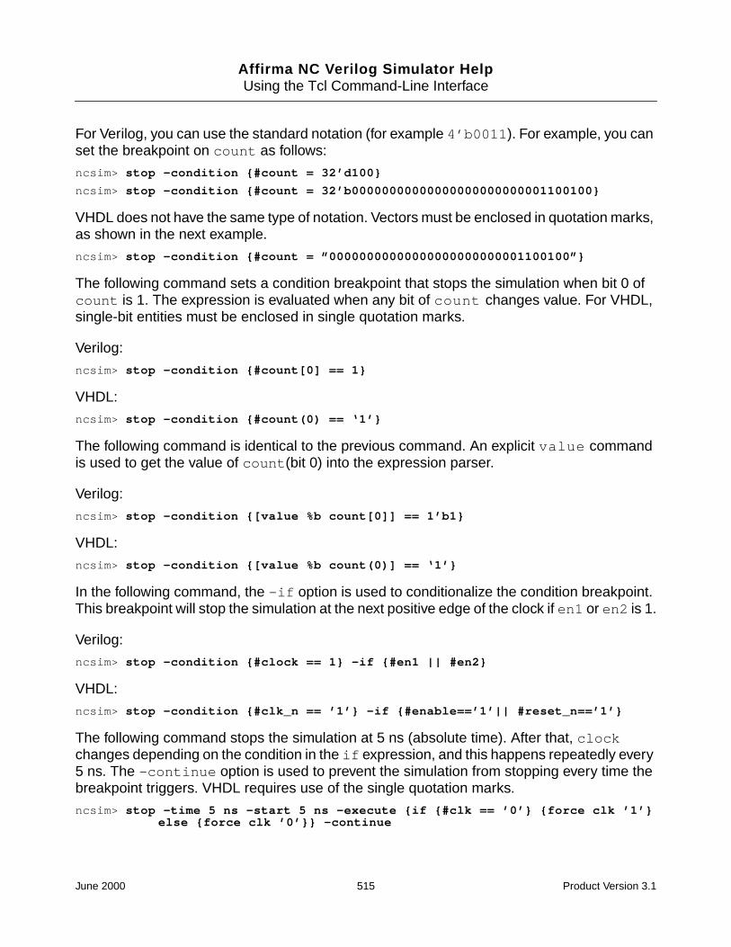
Affirma NC Verilog Simulator HelpUsing the Tcl Command-Line Interface
For Verilog, you can use the standard notation (for example 4’b0011 ). For example, you canset the breakpoint on count as follows:
ncsim> stop -condition {#count = 32’d100}
ncsim> stop -condition {#count = 32’b00000000000000000000000001100100}
VHDL does not have the same type of notation. Vectors must be enclosed in quotation marks,as shown in the next example.
ncsim> stop -condition {#count = ”00000000000000000000000001100100”}
The following command sets a condition breakpoint that stops the simulation when bit 0 ofcount is 1. The expression is evaluated when any bit of count changes value. For VHDL,single-bit entities must be enclosed in single quotation marks.
Verilog:
ncsim> stop -condition {#count[0] == 1}
VHDL:
ncsim> stop -condition {#count(0) == ‘1’}
The following command is identical to the previous command. An explicit value commandis used to get the value of count (bit 0) into the expression parser.
Verilog:
ncsim> stop -condition {[value %b count[0]] == 1’b1}
VHDL:
ncsim> stop -condition {[value %b count(0)] == ‘1’}
In the following command, the -if option is used to conditionalize the condition breakpoint.This breakpoint will stop the simulation at the next positive edge of the clock if en1 or en2 is 1.
Verilog:
ncsim> stop -condition {#clock == 1} -if {#en1 || #en2}
VHDL:
ncsim> stop -condition {#clk_n == ’1’} -if {#enable==’1’|| #reset_n==’1’}
The following command stops the simulation at 5 ns (absolute time). After that, clockchanges depending on the condition in the if expression, and this happens repeatedly every5 ns. The -continue option is used to prevent the simulation from stopping every time thebreakpoint triggers. VHDL requires use of the single quotation marks.
ncsim> stop -time 5 ns -start 5 ns -execute {if {#clk == ’0’} {force clk ’1’}else {force clk ’0’}} -continue
June 2000 515 Product Version 3.1

Affirma NC Verilog Simulator HelpUsing the Tcl Command-Line Interface
The following command stops the simulation when the value of the specified signal has thevalue x . Notice that in the Tcl expression, the case-equality operator ( === ) is used. For thisoperator, bits that are unknown are included in the comparison, and the result of theexpression is always 1 (true) or 0 (false).
ncsim> stop -create -condition {#top.load === 1’bx}
In the following command, the logical comparison operator ( = or ==) is used. These operatorsreturn the unknown value (x) if either operand is unknown. In a conditional expression, anunknown result is treated as false. Therefore, the following command will not stop thesimulation when the signal has the value x .
ncsim> stop -create -condition {#top.load == 1’bx}
Process Breakpoints
The following command sets a breakpoint that stops the simulation whenever the processcalled :load_action is executed.
ncsim> stop -process :load_action
Subprogram Breakpoints
The following command sets a breakpoint that stops the simulation when the VHDLsubprogram procedure1 is called.
ncsim> stop -subprogram procedure1
Created stop 1
ncsim> run
0 FS + 0 (stop 1: Subprogram :procedure1)
./scope_test.vhd:11 tmp1 := not tmp1;
The following command sets a breakpoint that stops the simulation when the VHDLsubprogram function2 is called.
ncsim> stop -subprogram function2
Created stop 1
ncsim> run
0 FS + 0 (stop 1: Subprogram :function2)
./scope_test.vhd:29 tmp5_local := tmp5 + 1;
June 2000 516 Product Version 3.1

Affirma NC Verilog Simulator HelpUsing the Tcl Command-Line Interface
Examples of Other stop Command Modifiers
The following command sequence illustrates the -show modifier. The first command createsa source line breakpoint called break1 ; the second creates an object breakpoint calledbreak2 . The third command shows the status of the two breakpoints.
ncsim> stop -line 12 -name break1
Created stop break1
ncsim> stop -object data -name break2
Created stop break2
ncsim> stop -show
break1 Enabled Line: ./shortdrive.v:12 (scope: top)
break2 Enabled Object top.data
In the following command sequence, breakpoint break1 is first disabled with the-disable modifier and then enabled with the -enable modifier.
ncsim> stop -show
break1 Enabled Line: ./shortdrive.v:12 (scope: top)
break2 Enabled Object top.data
ncsim> stop -disable break1
ncsim> stop -show
break1 Disabled Line: ./shortdrive.v:12 (scope: top)
break2 Enabled Object top.data
ncsim> stop -enable break1
ncsim>
The following command deletes breakpoint break1 .ncsim> stop -delete break1
To disable, enable, or delete the two breakpoints break1 and break2 , any of the followingcommands could be used.
ncsim> stop -delete *1 *2
ncsim> stop -delete break?
ncsim> stop -delete br*
The following command displays information on any breakpoint beginning with v or b.
ncsim> stop -show {[vb]*}
June 2000 517 Product Version 3.1

Affirma NC Verilog Simulator HelpUsing the Tcl Command-Line Interface
Tcl Expressions as Arguments
The stop command has two options that let you specify conditions. Both options require aTcl expression argument.
■ -condition
This option specifies that you are creating a condition breakpoint, as opposed to someother kind of breakpoint, such as a time or object breakpoint. A condition breakpointtriggers when any object named in the Tcl expression has an event that would trigger anobject breakpoint and the expression evaluates to non-zero, non-x, or non-z.
■ -if
This option can be used with any breakpoint type, including condition breakpoints. TheTcl expression argument is evaluated, and the stop triggers if the expression evaluatesto non-zero, non-x, or non-z.
There are two general rules to keep in mind when writing the Tcl expression:
■ Enclose the expression in braces to suppress immediate substitution of values.
{ tcl_expression }
Note: If you are using the SimVision analysis environment, these braces are includedon the Set Break form.
In the following example, the value of w[1] would be substituted with its current value(1’bx , for example) if there were no braces. No object would be named in theexpression by the time the stop command routine sees it, resulting in an error.
ncsim> stop -condition #w[1] == 1
ncsim> stop -condition {#w[1] == 1}
■ You must use either an explicit value command or the # character to get the object’svalue into the expression parser because the parser does not understand names. Forexample, the following command generates an error message.
ncsim> stop -time 100 ns -if {r[1] == 1}
Use the following commands:
Verilog:
ncsim> stop -time 100 ns -if {[value r[1]] == 1’b1}
ncsim> stop -time 100 ns -if {#r[1] == 1}
VHDL:
ncsim> stop -time 100 ns -if {[value r(1)] == ‘1’}
ncsim> stop -time 100 ns -if {#r(1) == ‘1’}
June 2000 518 Product Version 3.1

Affirma NC Verilog Simulator HelpUsing the Tcl Command-Line Interface
Format specifiers can be used with either the value command or the # sign. If you use the# sign, place the format specifier after the # sign. For example,
Verilog:
ncsim> stop -condition {[value %d out] = 12}
ncsim> stop -condition {#%dout = 12}
VHDL:
ncsim> stop -condition {[value %d out] = 12}
ncsim> stop -condition {#%dout = 1}
For VHDL, you must enclose vectors in quotation marks and single-bit entities in singlequotation marks.
For example:
Verilog:
ncsim> stop -condition {#clock == 1}
VHDL:
ncsim> stop -condition {#clock == ‘1’}
Verilog:
ncsim> stop -condition {#count = 4’b0101}
VHDL:
ncsim> stop -condition {#clock = “0101”}
In a Tcl expression, the single-equality operator ( = ), which is used for assignment in Verilog,is a logical comparison operator. In a Tcl expression, = is the same as the Verilog logicalcomparison operator ( == ). The following two expressions are the same:
{ #top.load = 1’b1 }
{ #top.load == 1’b1 }
These operators return the unknown value (x) if either operand is unknown. In a conditionalexpression, an unknown result is treated as false. For example, in the following stopcommand, the expression returns an unknown result, and is, therefore, false. This conditionalbreakpoint will not trigger when the signal top.load has the value x .
ncsim> stop -create -condition {#top.load == 1’bx}
To set a breakpoint that will stop when the value is x , use the case equality operator ( === ).The result of the expression is always 1 (true) or 0 (false). For example:
ncsim> stop -create -condition {#top.load === 1’bx}
June 2000 519 Product Version 3.1

Affirma NC Verilog Simulator HelpUsing the Tcl Command-Line Interface
See Appendix A, “Basics of Tcl,” for more details on basic Tcl syntax and on the extensionsto Tcl that have been added to handle types and operators of the Verilog and VHDL hardwaredescription languages.
June 2000 520 Product Version 3.1

Affirma NC Verilog Simulator HelpUsing the Tcl Command-Line Interface
strobe
The strobe command prints the values of specified VHDL or Verilog objects based on oneof the following specifications:
■ When a specified condition is true.
■ When a specified signal changes value.
■ At a specified time interval.
The strobe command is a Tcl procedure that uses the stop command to set a condition,object, or time breakpoint and then, when the breakpoint triggers, executes a valuecommand to print out the values of the specified objects in tabular format.
By default, the simulator prints the values of the specified objects using the default format ofthe value command. You can set the strobeFmt variable to specify a global format. Forexample:
ncsim> set strobeFmt %b
Note: You must reset the strobe after setting the strobeFmt variable.
You can also specify a format for individual objects. Enclose the object-format pair in curlybraces. For example:
ncsim> strobe -time 100 clk {data %b}
If you interrupt or stop the simulation (with CTRL/C or with an assert statement forexample), and then continue the simulation, the simulator does not print the header in thetabular output. To display the header again, set the strobeHeader variable to 1, as follows:
ncsim> set strobeHeader 1
Verilog objects in the design must have read access. See “Enabling Read, Write, orConnectivity Access to Simulation Objects” on page 211 for details on specifying access tosimulation objects.
You can only set one strobe at a time. Setting a new strobe automatically deletes the previousstrobe.
June 2000 521 Product Version 3.1

Affirma NC Verilog Simulator HelpUsing the Tcl Command-Line Interface
strobe Command Syntaxstrobe {-time time_spec | -object object_spec | -condition condition_spec }
object | { object format } [ object | { object format } ...]
strobe -delete
strobe -help
strobe Command Modifiers and Options
You must specify if you want to display signal values when a specified condition is true(-condition ), when a specified signal changes value (-object ), or at a specified timeinterval (-time ).
-condition condition_spec object | {object format } [ object |{object format } ...]
Display the values of the specified object(s) when the condition_spec is true.
The condition_spec argument is the same as in the stop command.
-object object_spec object | {object format } [ object |{object format } ...]
Display the values of the specified object(s) when the object specified by the object_specargument changes value.
With -object , you can specify only one object to monitor for a change in value. For example,the following command displays the values of y and z when x changes value.
ncsim> strobe -object x y z
The following command displays the value of y in the default format and the value of z inbinary when x changes value.
ncsim> strobe -object x y {z %b}
-time time_spec object | {object format } [ object | {object format } ...]
Display the values of the object(s) at the time interval specified by the time_specargument.
ncsim> strobe -time 100ns x y z
ncsim> strobe -time 100ns x {y %b} z
June 2000 522 Product Version 3.1

Affirma NC Verilog Simulator HelpUsing the Tcl Command-Line Interface
-delete
Deletes the strobe.
-help
Displays help on the strobe command.
You cannot use the help command to display help on the strobe command because it is aTcl procedure. The help command only displays help on simulator commands that areimplemented in C.
strobe Command Examples
The following command prints the values of signals clk , clr , data , and q every 100 ns.
ncsim> strobe -time 100 clk clr data q
Setting up strobe time - ’100’
ncsim> run
Time |clk |clr |data |q |
-----------------------------------------
100 NS |1’h1 |1’h1 |4’h0 |4’hx |
200 NS |1’h1 |1’h1 |4’h1 |4’h0 |
300 NS |1’h1 |1’h1 |4’h2 |4’h1 |
400 NS |1’h1 |1’h1 |4’h3 |4’h2 |
...
The following command prints the values of signals clk , clr , data (in binary), and q every100 ns.
ncsim> strobe -time 100ns clk clr {data %b} q
Setting up strobe time - ’100ns’
ncsim> run 300 ns
Time |clk |clr |data |q |
--------------------------------------------
100 NS |1’h1 |1’h1 |4’b0000 |4’hx |
200 NS |1’h1 |1’h1 |4’b0001 |4’h0 |
300 NS |1’h1 |1’h1 |4’b0010 |4’h1 |
Ran until 300 NS + 0
June 2000 523 Product Version 3.1

Affirma NC Verilog Simulator HelpUsing the Tcl Command-Line Interface
In the following command sequence, the simulation is run for 300 ns. When the simulation isresumed, the strobe header is not displayed. The strobeHeader variable is then set todisplay the header when the simulation is resumed.
ncsim> strobe -time 100 clk clr data q
Setting up strobe time - ’100’
ncsim> run 300
Time |clk |clr |data |q |
-----------------------------------------
100 NS |1’h1 |1’h1 |4’h0 |4’hx |
200 NS |1’h1 |1’h1 |4’h1 |4’h0 |
300 NS |1’h1 |1’h1 |4’h2 |4’h1 |
Ran until 300 NS + 0
ncsim> run 300
400 NS |1’h1 |1’h1 |4’h3 |4’h2 |
500 NS |1’h1 |1’h1 |4’h4 |4’h3 |
600 NS |1’h1 |1’h1 |4’h5 |4’h4 |
Ran until 600 NS + 0
ncsim> set strobeHeader 1
1
ncsim> run 300
Time |clk |clr |data |q |
-----------------------------------------
700 NS |1’h1 |1’h1 |4’h6 |4’h5 |
800 NS |1’h1 |1’h1 |4’h7 |4’h6 |
900 NS |1’h1 |1’h1 |4’h8 |4’h7 |
Ran until 900 NS + 0
To change the format globally, you can set the strobeFmt variable, as shown in the followingexample. You must reset the strobe after setting the strobeFmt variable.
ncsim> strobe -time 100 clk clr data q
Setting up strobe time - ’100’
ncsim> run 300
Time |clk |clr |data |q |
-----------------------------------------
100 NS |1’h1 |1’h1 |4’h0 |4’hx |
200 NS |1’h1 |1’h1 |4’h1 |4’h0 |
300 NS |1’h1 |1’h1 |4’h2 |4’h1 |
Ran until 300 NS + 0
ncsim> set strobeFmt %b
%b
June 2000 524 Product Version 3.1

Affirma NC Verilog Simulator HelpUsing the Tcl Command-Line Interface
ncsim> strobe -time 100 clk clr data q
Setting up strobe time - ’100’
ncsim> run 300
Time |clk |clr |data |q |
-----------------------------------------------
400 NS |1’b1 |1’b1 |4’b0011 |4’b0010 |
500 NS |1’b1 |1’b1 |4’b0100 |4’b0011 |
600 NS |1’b1 |1’b1 |4’b0101 |4’b0100 |
Ran until 600 NS + 0
The following command displays the values of clk , clr , and q when data changes value.
ncsim> strobe -object data clk clr q
Setting up strobe object - ’data’
ncsim> run 300 ns
Time |clk |clr |q |
-----------------------------------
0 NS |1’h0 |1’h1 |4’hx |
100 NS |1’h1 |1’h1 |4’hx |
200 NS |1’h1 |1’h1 |4’h0 |
Ran until 300 NS + 0
The following command displays the values of data , clk , clr , and q when data changesvalue.
ncsim> strobe -object data data clk clr q
Setting up strobe object - ’data’
ncsim> run 300 ns
Time |data |clk |clr |q |
-----------------------------------------
0 NS |4’h0 |1’h0 |1’h1 |4’hx |
100 NS |4’h1 |1’h1 |1’h1 |4’hx |
200 NS |4’h2 |1’h1 |1’h1 |4’h0 |
Ran until 300 NS + 0
June 2000 525 Product Version 3.1

Affirma NC Verilog Simulator HelpUsing the Tcl Command-Line Interface
The following command displays the values of data (in binary), clk , clr , and q (in hex)when data changes value. Notice that the object-format pair is enclosed in curly braces.
ncsim> strobe -object data {data %b} clk clr q
Setting up strobe object - ’data’
ncsim> run 300 ns
Time |data |clk |clr |q |
--------------------------------------------
0 NS |4’b0000 |1’h0 |1’h1 |4’hx |
100 NS |4’b0001 |1’h1 |1’h1 |4’hx |
200 NS |4’b0010 |1’h1 |1’h1 |4’h0 |
Ran until 300 NS + 0
The following command displays the values of the specified signals when data has the value3, decimal. The signal data is available from the top level of the hierarchy.
Verilog:
ncsim> strobe -condition {[value %d top.data] = 3} clk clr data q
VHDL:
ncsim> strobe -condition {[value %d :data] = 3} clk clr data q
If you are currently at the top level, you can omit the hierarchical path specification to data ,and write the two commands shown in the previous example as follows:
ncsim> strobe -condition {[value %d data] = 3} clk clr data q
Instead of using the value command to get the value of data into the expression evaluator,you can use #data . Include the format specifier after the # sign.
ncsim> strobe -condition {#%ddata = 3} clk clr data q
The following command displays the values of the specified signals when data has the value0010 (binary). For VHDL, you must enclose vectors in quotation marks.
Verilog:
ncsim> strobe -condition {#data = 4’b0010} clk clr data q
VHDL:
ncsim> strobe -condition {#data =”0010”} clk clr data q
June 2000 526 Product Version 3.1

Affirma NC Verilog Simulator HelpUsing the Tcl Command-Line Interface
The following command displays the values of the specified signals when bit 0 of data is 1.The expression is evaluated when any bit of data changes value. For VHDL, you mustenclose single-bit entities in single quotation marks.
Verilog:
ncsim> strobe -condition {#data[0] == 1} clk clr data q
VHDL:
ncsim> strobe -condition {#data(0) == ‘1’} clk clr data q
The following command is identical to the previous command except that it uses an explicitvalue command to get the value of data (bit 0) into the expression parser.
Verilog:
ncsim> strobe -condition {[value %b data[0]] == 1’b1} clk clr data q
VHDL:
ncsim> strobe -condition {[value %b data(0)] == ‘1’} clk clr data q
The following command displays the values of the specified signals if the value of top.loadhas the value x . Notice that in the Tcl expression, the case-equality operator ( === ) is used.For this operator, bits that are unknown are included in the comparison, and the result of theexpression is always 1 (true) or 0 (false).
ncsim> strobe -condition {#top.load === 1’bx} clk clr data q
In the following command, the logical comparison operator ( = or ==) is used. Theseoperators return the unknown value (x ) if either operand is unknown. In a conditionalexpression, an unknown result is treated as false. Therefore, the following command does notstop the simulation when the signal has the value x .
ncsim> strobe -condition {#top.load == 1’bx} clk clr data q
June 2000 527 Product Version 3.1

Affirma NC Verilog Simulator HelpUsing the Tcl Command-Line Interface
task
The task command lets you schedule Verilog tasks for execution. Verilog tasks are thosetasks that are implemented in the Verilog source code with a task declaration. You cannotuse the task command to schedule the execution of built-in or user-defined Verilog systemtasks, Verilog functions, VHDL functions, or VHDL procedures.
The task command schedules the specified task(s) to execute at the current simulation time.However, the task is not executed immediately (as is the case in Verilog-XL). The task beginsexecuting after you resume the simulation, and is executed at some point during the currentsimulation time. The simulator may execute other behaviors that are already scheduled forthe current simulation time before executing the scheduled task.
When scheduling tasks that may be called elsewhere (from within the Verilog code, from VPI,or from Tcl), you must remember that, because tasks in Verilog are static, multiple concurrentcalls to tasks can interfere with each other, stomping on the values of parameters andregisters within the task.
Parameters to tasks are static registers. You must set the input and inout parameters beforethe scheduled task runs by using a deposit command. You can schedule the task before orafter you deposit values to the input and inout parameters. Remember that intervening callsto the same task in the model can interfere with and overwrite the values that you depositedto the task parameters before the scheduled task actually runs.
You can read the value of output parameters after the task has completed by using the valuecommand.
Note: To deposit values to parameters and to read output parameters, the parameters musthave read/write access. See “Enabling Read, Write, or Connectivity Access to SimulationObjects” on page 211 for details on specifying access to simulation objects.
Disable statements in the Verilog code affect active tasks that you scheduled with the taskcommand in the same way that they affect tasks that are scheduled by the code in the model.
Once a task is scheduled, it becomes part of the model’s state. If you save a snapshot with atask that is scheduled or that is in progress, the task will still be scheduled or in progress whenyou restart that snapshot. Tasks that are scheduled or that are in progress at the time of thesave will be the only tasks that are scheduled or in progress after the restart.
task Command Syntaxtask [-schedule] task_name [ task_name ...]
June 2000 528 Product Version 3.1

Affirma NC Verilog Simulator HelpUsing the Tcl Command-Line Interface
task Command Modifiers and Options
[-schedule] task_name [task_name ...]
Schedule the specified task(s) for execution at the current simulation time.
The task begins executing after the simulation is resumed, and at some point during thecurrent simulation time. Other behaviors that are already scheduled for the current simulationtime may execute before the scheduled task starts.
The -schedule modifier is optional.
task Command Examples
The following source code is used in the examples in this section:
module top;
reg out;
reg i1,i2,i3;
reg clock;
initial
#10000 $display("DONE");
always
@(posedge clock) print_task1(out,i1,i2,i3);
task print_task1;
output [31:0] out;
input [31:0] i1;
input [31:0] i2;
input [31:0] i3;
begin
out = i1 + i2 + i3;
$display("%t %0d %0d %0d %0d", $time,out,i1,i2,i3);
end
endtask
task print_task2;
output [31:0] out;
input [31:0] i1;
input [31:0] i2;
input [31:0] i3;
begin
June 2000 529 Product Version 3.1

Affirma NC Verilog Simulator HelpUsing the Tcl Command-Line Interface
out = i1 * i2 * i3;
$display("%t %0d %0d %0d %0d",$time,out,i1,i2,i3);
end
endtask
endmodule
The following sequence of commands schedules the task called print_task1 for executionand sets the input parameter values that will be in effect when the task runs. The runcommand then continues the simulation so that the task is executed.
ncsim> run 50
ncsim> task -schedule print_task1
ncsim> deposit print_task1.i1 1
ncsim> deposit print_task1.i2 1
ncsim> deposit print_task1.i3 1
ncsim> run 1
50 3 1 1 1
Ran until 51 NS + 0
The following command specifies the full path to the task. The -schedule modifier is notrequired.
ncsim> task top.print_task1
To schedule more than one task, specify the task names on the command line and thendeposit values to the input and inout parameters.
ncsim> task print_task1 print_task2
ncsim> deposit print_task1.i1 1
ncsim> deposit print_task1.i2 1
ncsim> deposit print_task1.i3 1
ncsim> deposit print_task2.i1 1
ncsim> deposit print_task2.i2 1
ncsim> deposit print_task2.i3 1
ncsim> run 1
0 3 1 1 1
0 1 1 1 1
Ran until 1 NS + 0
June 2000 530 Product Version 3.1

Affirma NC Verilog Simulator HelpUsing the Tcl Command-Line Interface
If you want to schedule a task at a specific time, set a time breakpoint, advance the simulationto that time, and then schedule the task.
ncsim> stop -time 50 -absolute
ncsim> run
ncsim> task print_task2
ncsim> (deposit values to parameters)
ncsim> run
In the following sequence of commands, a line breakpoint is set on the first statement in thetask so that the simulation stops when the task is about to execute. Parameter values are thendeposited immediately before the execution of the task.
ncsim> stop -line 18
ncsim> run
ncsim> deposit i1 0
ncsim> deposit i2 1
ncsim> deposit i3 1
ncsim> run 1
100 2 0 1 1
Ran until 101 NS + 0
In the following sequence of commands, a line breakpoint is set on the first statement in thetask. After depositing values to the input parameters, a run -return command is issued.This stops the simulation when the task returns so that you can read output parameters assoon as they are available.
ncsim> stop -line 18
Created stop 1
ncsim> run
100 NS + 0 (stop 1: ./test2.v:18)
./test2.v:18 begin
ncsim> deposit i1 1
ncsim> deposit i2 0
ncsim> deposit i3 0
ncsim> run -return
100 1 1 0 0
./test2.v:10 @(posedge clock) print_task1(out,i1,i2,i3);
June 2000 531 Product Version 3.1

Affirma NC Verilog Simulator HelpUsing the Tcl Command-Line Interface
time
The time command displays the current simulation time scaled to the specified unit. The unitcan be:
■ a time unit that you specify
■ auto —use the largest base unit that makes the numeric part of the time an integer
■ module —use the timescale of the current debug scope
The simulation time can be displayed in the following time units:
■ fs —femtoseconds
■ ps —picoseconds
■ ns —nanoseconds
■ us —microseconds
■ ms—milliseconds
■ sec —seconds
If no unit is given, the value of the $display_unit variable is used. This variable is set toauto by default.
You also can display the time in 10 or 100 times the base unit. For example,
ncsim> time fs
ncsim> time 10fs
ncsim> time 100fs
time Command Syntaxtime [[10 | 100] time_unit | auto | module]
-delta
-nounit
June 2000 532 Product Version 3.1

Affirma NC Verilog Simulator HelpUsing the Tcl Command-Line Interface
time Command Modifiers and Options
-delta
Includes the delta cycle count.
At any given simulation time, values of nets are first updated and then behaviors that aresensitive to those nets are executed. This two step process may be repeated any number oftimes because of zero-delays. The delta cycle count represents the number of times theprocess is repeated for the given simulation time.
-nounit
Does not include the time unit.
time Command Examples% ncsim -tcl board
ncsim: v1.0.(p2): (c) Copyright 1995, 1996 Cadence Design Systems, Inc.
ncsim> run 100 ns
5 count= X, f=x, af=x
Ran until 100 NS + 0
The following command displays the current simulation time in ns.
ncsim> time ns
100 NS
The following command displays the current simulation time in fs.
ncsim> time fs
100000000 FS
The following command displays the current simulation time in 100 times the base unit of fs.
ncsim> time 100fs
1000000 100FS
The following commands illustrate the auto keyword, which displays the time using thelargest base unit that makes the numeric part of the time an integer.
ncsim> time fs
100000000 FS
ncsim> time auto
100 NS
June 2000 533 Product Version 3.1

Affirma NC Verilog Simulator HelpUsing the Tcl Command-Line Interface
The following command displays the current simulation time using the timescale of the currentdebug scope.
ncsim> time module
100 NS
The following command displays the current simulation time using the timescale of the currentdebug scope and including the delta cycle count.
ncsim> time module -delta
100 NS + 0
The following command displays the current simulation time with no time unit.
ncsim> time -nounit
100
June 2000 534 Product Version 3.1

Affirma NC Verilog Simulator HelpUsing the Tcl Command-Line Interface
value
The value command prints the current value of the specified objects using the last formatspecifier preceding the object name argument. If no format is specified, a default format isused.
Verilog objects specified as arguments to the value command must have read access. Anerror is printed if an object does not have read access.
value Command Syntaxvalue [ format ...] object_name ...
For Verilog, the valid formats are:
To revert to the default format, use %.
Format Specifier Format
%c character
%s string
%b binary
%d decimal
%o octal
%x unsigned hexadecimal
%h same as %x
%f floating-point number
%e real number in mantissa-exponent form
%g use %e or %f, whichever is shorter
%t decimal time scaled from the timescale of theobject’s module to the simulation’s timescale
%v strength value—wires only
June 2000 535 Product Version 3.1

Affirma NC Verilog Simulator HelpUsing the Tcl Command-Line Interface
If no format is specified, the default format depends on the object type. The following defaultsare used:
■ time—%d
■ integer—%d
■ real—%g
■ reg—$vlog_format
■ wire—$vlog_format
where $vlog_format is a predefined Tcl variable that defaults to %h. You can set thisvariable to %b, %o, or %d.
For VHDL, values are returned in a format that resembles the appropriate VHDL syntax forthe object type. If one of the radix format specifiers (%b, %o, %d, or %x) is given, the formataffects the format of integer values and of bit_vector and std_logic_vector values. Otherwise,the format specifier is ignored for VHDL values.
value Command Modifiers and Options
None.
value Command Examples
The following command displays the value of the signal data .
ncsim> value top.u1.data
4’h2
If the current debug scope has been set to instance u1, you can display the value of data withthe following command.
ncsim> value data
4’h2
The following sequence of value commands displays the current value of data in a varietyof formats.
ncsim> value data
4’h2
ncsim> value %o data
4’o02
June 2000 536 Product Version 3.1

Affirma NC Verilog Simulator HelpUsing the Tcl Command-Line Interface
ncsim> value %b data
4’b0010
ncsim> value %d data
4’d2
ncsim> value %g data
2
ncsim> value %f data
2.000000
ncsim> value %e data
2.000000e+00
ncsim> value %b data %d q
4’b0010 4’d1
ncsim> value % data %d data %b data
4’h2 4’d2 4’b0010
The following command shows the error message that is displayed when you run inregression mode and then use the value command on a Verilog object that does not haveread access.
ncsim> value clk
ncsim: *E,RDACRQ: Object does not have read access: hardrive.clk.
In the following VHDL example, the stack -show command displays the current subprogramcall stack. The process (process1 ) is displayed as nest-level 0, the base of the stack. Thesubprogram function1 is :process1[1] , and the subprogram function2 is:process1[2] .
■ The first value command displays the value of the variable tmp5 in the current debugscope.
■ The second value command displays the value of the variable var1 in :process1 .
■ The third value command displays the value of the signal tmp4 in :process1[1] (thatis, in function1 ).
■ A scope command is then executed to set the scope to function1 . The last valuecommand displays the value of tmp4 .
ncsim> stop -subprogram function1
Created stop 1
ncsim> run
0 FS + 0 (stop 1: Subprogram :function1)
./test.vhd:36 tmp4_local := function2 (tmp4);
ncsim> run -step
./test.vhd:29 tmp5_local := tmp5 + 1;
June 2000 537 Product Version 3.1

Affirma NC Verilog Simulator HelpUsing the Tcl Command-Line Interface
ncsim> stack -show // Display the current call stack
2: Scope: :process1[2] Subprogram:@work.e(a):function2
File: /usr1/belanger/inca/vhdl/subprogram_debug/scope_test/test.vhd
Line: 29
1: Scope: :process1[1] Subprogram:@work.e(a):function1
File: /usr1/belanger/inca/vhdl/subprogram_debug/scope_test/test.vhd
Line: 36
0: Scope: :process1
File: /usr1/belanger/inca/vhdl/subprogram_debug/scope_test/test.vhd
Line: 52
ncsim> scope -show // Display the current debug scope
Directory of scopes at current scope level:
Current scope is (:process1[2])
Highest level modules:
Top level VHDL design unit:
entity (e:a)
VHDL Package:
STANDARD
ATTRIBUTES
std_logic_1164
TEXTIO
ncsim> value tmp5 // Display the value of tmp5 in :process1[2]// i.e., function2
1
ncsim> value :process1:var1 // Display the value of var1 in :process1
’0’
ncsim> value :process1[1]:tmp4 // Display the value of tmp4 in :process1[1]// i.e., function1
1
ncsim> scope -set :process1[1] // Set scope to function1 (:process1[1])
ncsim> value tmp4 // Display the value of tmp4
1
June 2000 538 Product Version 3.1

Affirma NC Verilog Simulator HelpUsing the Tcl Command-Line Interface
version
The version command displays the version number of ncsim.
You can also print the version number by invoking the simulator with the -version option.
% ncsim -version
version Command Syntaxversion
version Command Modifiers and Options
None.
version Command Examplesncsim> version
ncsim: v3.0.(p1)
June 2000 539 Product Version 3.1

Affirma NC Verilog Simulator HelpUsing the Tcl Command-Line Interface
where
The where command displays the current location of the simulation. This includes the currentsimulation time and the current scope.
where Command Syntaxwhere
where Command Modifiers and Options
None.
where Command Examplesncsim> where
TIME: 3400 NS + 0
Scope is (board.counter)
ncsim>
ncsim> where
TIME: 100 NS + 0
Scope is (:top.VENDING)
ncsim>
June 2000 540 Product Version 3.1

Affirma NC Verilog Simulator HelpUsing the Tcl Command-Line Interface
Verilog-XL and NC Verilog Simulator Interactive DebugCommands
Simulation Control Commands
Description XL Command Tcl Command
Run . run
Run 100 ns #100 $stop; run 100 ns
Run 1 event ; run -step
Exit simulator $finish; exit or finish
Save simulation $save(“fname”); save cellname
Restore simulation $restart(“fname”); restore cellname
Reset to time 0 $reset; reset
Breakpoint Commands
Description XL Command Tcl Command
Relative time breakpoint #100 $stop; stop -time 100 ns-delbreak 1
Absolute time breakpoint $db_breakbeforetime(100); stop -time 100 ns-absolute
Object breakpoint @(clk) $stop;
or
$db_breakoncewhen (clk);
stop -object clk-delbreak 1
Condition breakpoint wait (A&B) $stop; stop -condition {#A& #B} -delbreak 1
Source Line breakpoint $db_breakonceatline(23); stop -line 23-delbreak 1
June 2000 541 Product Version 3.1

Affirma NC Verilog Simulator HelpUsing the Tcl Command-Line Interface
Show active breakpoint $history;
(* denotes active commands)
To display $db breakpoints:
$db_showbreak;
stop -show
Disable or deletebreakpoints
-interactive_cmd_num
or if a $db breakpoint:
$db_disablebreak( break_num );
$db_deletebreak( break_num );
stop -deletebreak_num
stop -disablebreak_num
Enabling breakpoint $db_enablebreak( break_num );
stop -enablebreak_num
Simulation Debug Commands
Description XL Command Tcl Command
Force identifier to a value force clk = 1; force clk = 1
Release forced identifier release clk; release clk
Deposit value on identifier $deposit(clk, 1); deposit clk = 1
Display current simulation time $display($time); time or time -ns
Display drivers of net or reg $showvars(clk); drivers clk
Display value of object $display(clk); value clk
Display value of objectformatted
$display(“clk = %b”,clk);
puts “clk = [value%b clk]”
Display value of objectw/o carriage return
$write(“clk = %b”, clk); puts-nonewline “clk =[value %b clk]”
Breakpoint Commands
Description XL Command Tcl Command
June 2000 542 Product Version 3.1

Affirma NC Verilog Simulator HelpUsing the Tcl Command-Line Interface
Display value of all variables incurrent scope
$showvariables; scope -drivers
Display instances in currentscope
$showscopes; scope -show
Display current debug scope : scope
Set debug scope $scope(A.B.C); scope A.B.C
Set debug scope up one level scope -up
VCD Waveform Commands
Description XL Command Tcl Command
Open VCD file $dumpfile(“ fname .vcd”);
database -default-vcd fname -intofname .vcd
Add signal to VCD file $dumpvars(0,signame );
probe signame -vcd
Add all signals in an instanceto VCD file
$dumpvars(1,instname );
probe instname -all-vcd
Add all signals in an instanceand all subinstances to VCDfile
$dumpvars(0,instname );
probe instname -all-depth all -vcd
Add all ports in an instance toVCD file
probe instname -ports-vcd
Add all ports in an instanceand all subinstances to VCDfile
probe instname -ports-depth all -vcd
Show probes probe -show
Delete probe probe -deleteprobename
Simulation Debug Commands
Description XL Command Tcl Command
June 2000 543 Product Version 3.1

Affirma NC Verilog Simulator HelpUsing the Tcl Command-Line Interface
Show open databases database -show
Disable waveform capture $dumpoff; database -disablefname
Enable waveform capture $dumpon; database -enablefname
SHM Waveform Commands
Description XL Command Tcl Command
Open SHM database $shm_open (“ fname .shm”); database -default-shm fname -intofname .shm
Add signal to SHMdatabase
$shm_probe( signame ); probe signame -shm
Add all signals in aninstance to SHM database
$shm_probe(“A”,instname );
probe instname -all-shm
Add all signals in aninstance and allsubinstances to SHMdatabase
$shm_probe(“AC”,instname );
probe instname -all-depth all -shm
Add all ports in aninstance to SHM database
$shm_probe( instname ); probe instname-ports -shm
Add all ports in aninstance and allsubinstances to SHMdatabase
$shm_probe(“C”,instname );
probe instname-ports -depth all-shm
Show probes probe -show
Disable probe probe -disableprobename
VCD Waveform Commands
Description XL Command Tcl Command
June 2000 544 Product Version 3.1

Affirma NC Verilog Simulator HelpUsing the Tcl Command-Line Interface
Enable probe probe -enableprobename
Delete probe probe -deleteprobename
Show open databases database -show
Disable waveform capture database -disablefname
Enable waveform capture database -enablefname
Close SHM database $shm_close; database -closefname
Other Commands
Description XL Command Tcl Command
Command alias `define h $history; alias h history
Command history $history; history
Replay previouscommand
cmd_number ! cmd_number
Save tcl enviornment save -environment fname
Load file of interactivecommands
$input(“ fname ”); source fname
Decompile Verilog source $list( instname ); scope -list instname
Display message to logfile
$display(“HelloWorld”);
puts “Hello World”
Create additional log file set fileid [ open“ logfilename ” w]
Display message toalternate log file
puts $fileid “clk =[value clk]”
SHM Waveform Commands
Description XL Command Tcl Command
June 2000 545 Product Version 3.1

Affirma NC Verilog Simulator HelpUsing the Tcl Command-Line Interface
Help help
Help on a specificcommand
help command
Other Commands
Description XL Command Tcl Command
June 2000 546 Product Version 3.1

Affirma NC Verilog Simulator Help
13Using the Affirma™ SimVision AnalysisEnvironment
The SimVision analysis environment is the common graphical debug environment forCadence simulators. SimVision builds upon Cadence’s interleaved native-compiled codearchitecture to provide a powerful design solution. The unified simulation environmentoptimizes performance and productivity and helps you master the tools you need to designand verify complex systems.
The SimVision environment features advanced debug and analysis tools and innovative high-level design and visualization capabilities. These tools include:
■ The SimControl window, which allows you to directly interact with the simulator. You cansingle step, trace signals, set breakpoints, and observe signals to verify your designs.SimControl also includes three other debug tools:
❑ The Watch Objects Window, which lets you observe the value of selected signals.
❑ The Navigator, which shows you signal values at any level of a design hierarchy.
❑ The Signal Flow Browser, which lets you trace signals to find the source of aproblem.
■ Signalscan waves—Lets you display waveforms.
■ Comparescan—Lets you compare SHM and VCD waveform databases.
You can invoke the SimVision debug environment in post-processing mode. The SimVisionPost Processing Environment (PPE) lets you analyze simulation results stored in an SHMdatabase and debug your design without using a simulator license. The PPE gives youaccess to all SimVision tools available in interactive mode, and the features of each tool arevirtually identical to those in interactive mode.
If you are using one of the NC simulators (Affirma™ NC Verilog simulator, Affirma™ NCVHDL simulator, or Affirma™ NC simulator), invoke SimControl by including the -gui optionwhen you invoke the ncsim simulator.
% ncsim -gui snapshot_name
June 2000 547 Product Version 3.1

Affirma NC Verilog Simulator HelpUsing the Affirma™ SimVision Analysis Environment
If you are using Verilog-XL, invoke SimControl with the +gui option.
% verilog +gui source_filenames
The Product Notes and Known Problems and Solutions for the various SimVisioncomponents are included in the Product Notes and KPNS for your simulator.
See the Affirma SimVision Analysis Environment documentation for details on using thedebug environment.
For a good introduction to using the SimVision analysis environment, see SimVisionAnalysis Environment for Verilog-XL. Although this tutorial is written specifically for usewith the Verilog-XL simulator, it is also highly recommended for NC Verilog simulator usersdespite some small differences in the graphical interface.
To use the tutorial with the NC Verilog simulator, run NC Verilog with the ncverilogcommand and the same Verilog-XL command-line arguments. Two additional options,+access+ and +linedebug , are required to use some features illustrated in the tutorial.These options provide read, write, and connectivity access to all objects in the design andenable single stepping and the setting of line breakpoints. For performance reasons, theseoptions are turned off by default. The command for running the NC Verilog simulator on theexample used in the tutorial is:
% ncverilog +gui +access+rwc +linedebug xl_options source_files
or:
% ncverilog +gui +access+rwc +linedebug -f xl_arguments_file
June 2000 548 Product Version 3.1

Affirma NC Verilog Simulator Help
14Timing Checks
This chapter contains the following sections:
■ Overview
■ Timing Check System Tasks
■ Using Edge-Control Specifiers
■ Using Notifiers
■ Enabling Timing Checks with Conditioned Events
■ Negative Timing Check Limits in $setuphold and $recrem
■ Timing Violation Messages
■ SDF Annotation of Timing Checks
June 2000 549 Product Version 3.1

Affirma NC Verilog Simulator HelpTiming Checks
Overview
A timing check verifies the timing performance of a design by making sure that critical eventsoccur within given time limits. A timing check performs the following steps:
1. Determines the elapsed time between two events.
2. Compares the elapsed time to a specified minimum or maximum time limit.
3. Reports a timing violation if the elapsed time occurs outside the specified time window.
Timing check information can be included by using the timing check system tasks availablein the Verilog HDL or by using SDF annotation. This topic deals primarily with using thesystem tasks. See “SDF Annotation of Timing Checks” on page 585 for details on SDFannotation.
The timing check system tasks are invoked in specify blocks. They can contain:
■ Edge-control specifiers, which control events in timing checks based on specific edgetransitions between 0, 1, and x . (See “Using Edge-Control Specifiers” on page 568 fordetails.)
■ Notifiers, which specify user-defined responses to timing violations. (See“UsingNotifiers” on page 569 for details.)
■ Conditioned events, which tie the occurrence of timing checks to the value of aconditioning signal. (See “Enabling Timing Checks with Conditioned Events” onpage 572 for details.)
(See “Specify Blocks” on page 599 for details on using these statements.)
You can invoke the following timing check system tasks:
■ $setup
■ $hold
■ $setuphold
■ $width
■ $period
■ $skew
■ $recovery
■ $removal
June 2000 550 Product Version 3.1

Affirma NC Verilog Simulator HelpTiming Checks
■ $recrem
■ $nochange
Note: If you do not want to execute timing checks, you can improve processing performanceby disabling timing checks by elaborating with the -notimingchecks option. For example,
% ncelab -notimingchecks top
Timing Check System Tasks
$setup
The $setup system task determines whether a data signal remains stable long enoughbefore a transition in a control signal, such as a clock signal that latches data in memory. Aviolation occurs when a change to the data signal occurs within a specified time limit beforethe transition at the control signal. The following figure illustrates the violation region specifiedby the $setup system task.
The $setup system task has the following format:
$setup( data_event , reference_event , setup_limit [, notifier ]);
The $setup system task arguments are as follows:
$setup Arguments Description
data_event Transition at a data signal that initiates the timing check. This is amodule input or inout that is a scalar or vector net.
reference_event Transition at a control signal that establishes the reference timefor tracking timing violations on the data event. This is a moduleinput or inout that is a scalar or vector net.
June 2000 551 Product Version 3.1

Affirma NC Verilog Simulator HelpTiming Checks
Note: If the reference event and the data event occur simultaneously, $setup performs thetiming check before it records the new data event value. Therefore, no violation is reported.
Example:
In the following example, the $setup system task sets up a time window 10 time units beforea positive transition on clock . A timing violation is reported if data transitions within thisinterval.
specify
specparam setup_param=10;
$setup( data, posedge clock, setup_param );
endspecify
$hold
The $hold system task determines whether a data signal remains stable long enough aftera transition in a control signal, such as a clock signal that latches data in a memory. Thefollowing figure illustrates the violation region specified by the $hold system task.
The $hold system task has the following format:
$hold( reference_event , data_event , hold_limit [, notifier ]);
setup_limit Positive constant expression or specparam that specifies theminimum interval between the data event and the referenceevent. Any change to the data signal within this interval results ina timing violation.
notifier (optional) Register whose value is updated whenever a timing violationoccurs. You can use notifiers to define responses to timingviolations. (See “Using Notifiers” on page 569 for details.)
$setup Arguments Description
June 2000 552 Product Version 3.1

Affirma NC Verilog Simulator HelpTiming Checks
The $hold system task arguments are as follows:
Note: If the reference event and the data event occur at the same time, the $hold timingcheck records the new reference event time before it performs the timing check and aviolation is reported.
Example:
In the following example, $hold reports a violation if the time that elapses from the referenceevent (posedge clk ) to a change in data is smaller than hold_param (11). The notifier,flag , detects the timing violation behaviorally and performs some user-defined action.
specify
specparam hold_param=11;
$hold( posedge clk, data, hold_param, flag ) ;
endspecify
$setuphold
The $setuphold task combines the functionality of $setup and $hold into one systemtask. It also offers additional functionality in that you can specify a negative time specificationfor the setup limit or for the hold limit.
The $setuphold system task has the following format:
$setuphold( reference_event , data_event , setup_limit , hold_limit
[, notifier ] [, tstamp_cond ] [, tcheck_cond ]
[, delayed_reference ] [, delayed_data ] );
$hold Arguments Description
reference_event Module input or inout transition at a control signal that establishesthe reference time.
data_event Module input or inout transition at a data signal that initiates atiming check against the value in hold_limit .
hold_limit Positive constant expression or specparam that specifies theinterval between the reference event and data event. Any changeto the data signal within this interval results in a timing violation. Ifhold_limit is 0, a timing check does not occur.
notifier (optional) Register whose value is updated whenever a timing violationoccurs. You can use notifiers to define responses to timingviolations. (See “Using Notifiers” on page 569 for details.)
June 2000 553 Product Version 3.1

Affirma NC Verilog Simulator HelpTiming Checks
The $setuphold system task arguments are as follows:
$setupholdArguments Description
reference_event Transition at a control signal that establishes the reference time fortracking timing violations on the data event. This is a module inputor inout that is a scalar or vector net. The reference_eventargument represents the lower bound event for $hold and theupper bound event for $setup .
data_event Transition at a data signal that initiates the timing check. This is amodule input or inout that is a scalar or vector net. Thedata_event argument represents the upper bound event for$hold and the lower bound event for $setup .
setup_limit Constant expression or specparam that specifies the minimuminterval between the data event and the reference event. Anychange to the data signal within this interval results in a timingviolation.
You can specify negative times for either the setup_limit orhold_limit arguments. The sum of the two arguments mustbe 0 or greater.
hold_limit Constant expression or specparam that specifies the intervalbetween the reference event and data event. Any change to thedata signal within this interval results in a timing violation.
You can specify negative times for either the setup_limit orhold_limit arguments. The sum of the two arguments mustbe 0 or greater.
notifier (optional) Register whose value is updated whenever a timing violationoccurs. You can use notifiers to define responses to timingviolations. (See “Using Notifiers” on page 569 for details.)
tstamp_cond(optional)
Places a condition on the stamp event. For the setup check of$setuphold , this argument places a condition on the transition ofthe data signal. For the hold check of $setuphold , this argumentplaces a condition on the transition of the reference signal.
tcheck_cond(optional)
Places a condition on the check event. For the setup check of$setuphold , this argument places a condition on the transition ofthe reference signal. For the hold check of $setuphold , thisargument places a condition on the transition of the data signal.
June 2000 554 Product Version 3.1

Affirma NC Verilog Simulator HelpTiming Checks
Absent optional parameters must be indicated as null parameters by using commas. Do notadd one or more commas after the last argument. For example, the following $setupholdtask includes a tcheck_cond argument:
$setuphold(posedge clk, data, 2, 3, , , tcheck_cond);
Note: You cannot condition a $setuphold timing check by using the tstamp_cond ortcheck_cond arguments and a conditioned event. If you attempt to use both methods, onlythe parameters in the tstamp_cond and tcheck_cond arguments are effective, and awarning message is generated.
Example 1:
The following example shows how the $setuphold system task combines the functionalityof $setup and $hold . The following invocation:
$setuphold(posedge clk, data, 3, 2);
is equivalent to the following two system tasks:
$setup( data, posedge clk, 3 );
$hold( posedge clk, data, 2 );
Example 2:
The following example illustrates $setuphold with positive time specifications for bothsetup_limit and hold_limit arguments.
specify
specparam tSU=16, tHLD=17;
$setuphold( posedge clk, data, tSU, tHLD );
endspecify
In this example, $setuphold reports a violation if the interval from a transition on the datasignal to the positive edge of clk is less than tSU (16), enacting its $setup component. Italso reports a violation if the interval from the positive edge of clk to a transition on the datasignal is less than tHLD (17), enacting its $hold component.
delayed_reference(optional)
A delayed version of the reference signal generated by a negativetiming check. See “Negative Timing Check Limits in $setupholdand $recrem” on page 574 for more information.
delayed_data(optional)
A delayed version of the data signal generated by a negativetiming check. See “Negative Timing Check Limits in $setupholdand $recrem” on page 574 for more information.
$setupholdArguments Description
June 2000 555 Product Version 3.1

Affirma NC Verilog Simulator HelpTiming Checks
The following figure shows the violation region:
Example 3:
You can specify negative times for either the setup_limit or hold_limit arguments.The sum of the two arguments must be 0 or greater.
■ A negative setup_limit value specifies a period following a change in the referencesignal.
■ A negative hold_limit value specifies a period preceding a change in the referencesignal.
If you use negative time specifications, you must use the -neg_tchk option on the commandline when you invoke the elaborator. If you do not specify this option, negative limits are setto 0 in the description or annotation, and a warning is issued.
The following figure illustrates the violation region for the following $setuphold , whichspecifies a negative setup limit:
$setuphold( posedge clk, data, -2, 4);
The following figure illustrates the violation region when you specify a negative hold limit.
June 2000 556 Product Version 3.1

Affirma NC Verilog Simulator HelpTiming Checks
$setuphold( posedge clk, data, 4, -2 );
$width
The $width system task specifies the duration of signal levels from one edge transition tothe opposite edge transition. A violation occurs when the pulse width is smaller than thespecified limit. The following figure illustrates how a violation occurs with the $width systemtask.
The syntax for the $width system task is as follows:
$width( reference_event , limit [, threshold , notifier ]);
Notice that no data_event argument is passed to $width . The data event for $width isderived from the reference event and is the reference event signal with the opposite edge.
June 2000 557 Product Version 3.1

Affirma NC Verilog Simulator HelpTiming Checks
The $width system task arguments are as follows:
If you specify more than one edge control specifier, the edges must be either all rising (anyof 01, 0X, X1) or all falling (any of 10,1X, X0).
Example 1:
The following $width system task reports a violation if the interval from the reference event(negedge clr ) to the implicit data event (posedge clr ) is less than the limit specified bywidth_param (12). Note that the data event and the reference event never occursimultaneously because they are triggered by opposite transitions.
specify
specparam width_param=12;
$width( negedge clr, width_param );
endspecify
$width Arguments Description
reference_event Transition at a control signal that establishes the reference timefor tracking timing violations on the data event. This argumentmust be an edge-triggered event. A compilation error occurs if thereference event is not an edge specification.
limit Positive constant expression or specparam that specifies theminimum interval between the time of the reference event and thetime of the implicit data event.
threshold (optional) Positive constant expression or specparam that specifies thelargest ignored pulse width. This argument is used for timinganalysis by Veritime. NC Verilog ignores threshold , butcompiles system calls to $width that contain this argument.
notifier (optional) Register whose value is updated whenever a timing violationoccurs. You can use notifiers to define responses to timingviolations. (See “Using Notifiers” on page 569 for details.)
June 2000 558 Product Version 3.1

Affirma NC Verilog Simulator HelpTiming Checks
Example 2:
You cannot use null arguments for $width . If you pass a notifier argument, you mustalso supply the threshold argument. However, you do not have to specify either of thesearguments. The following example shows legal and illegal calls.
// Legal calls
$width( negedge clr, lim );
$width( negedge clr, lim, thresh, notif );
$width( negedge clr, lim, 0, notif );
// Illegal calls
$width( negedge clr, lim, , notif );
$width( negedge clr, lim, notif );
$period
The $period system task specifies the duration of signal levels from one edge transition tothe same edge transition. A violation occurs when the pulse width is smaller than thespecified limit. The following figure illustrates how a violation occurs with the $periodsystem task.
The $period system task has the following format:
$period( reference_event , limit [, notifier ]);
Notice that no data_event argument is passed to $period . The data event for $periodis derived from the reference event and is the reference event signal with the same edge.
June 2000 559 Product Version 3.1

Affirma NC Verilog Simulator HelpTiming Checks
The $period system task arguments are as follows:
If you specify more than one edge control specifier, the edges must be either all positive (01 ,0X, X1) or all negative (10 , 1X, X0).
Example:
In the following example, the $period system task reports a violation if the time between thereference event (negedge clk ) and the implicit data event (the next negedge clk ) is lessthan period_param (13).
specify
specparam period_param=13;
$period( negedge clk, period_param ) ;
endspecify
$period Arguments Description
reference_event Transition at a control signal that establishes the reference timefor tracking timing violations on the data event. This argumentmust be an edge-triggered event. A compilation error will occur ifthe reference_event is not an edge specification.
limit Positive constant expression or specparam that specifies theminimum interval between the time of the reference event and thetime of the implicit data event.
notifier (optional) Register whose value is updated whenever a timing violationoccurs. You can use notifiers to define responses to timingviolations. (See “Using Notifiers” on page 569 for details.)
June 2000 560 Product Version 3.1

Affirma NC Verilog Simulator HelpTiming Checks
$skew
The $skew system task specifies the maximum delay allowable between two signals. Aviolation occurs when signals are too far apart. The following figure shows how a violationoccurs with the $skew system task.
The $skew system task has the following format:
$skew( reference_event , data_event , limit [, notifier ]);
The $skew system task arguments are as follows:
The $skew system task records the new time of the reference event before it performs thetiming check. If the reference event and the data event occur at the same time, $skew doesnot report a timing violation.
$skew Arguments Description
reference_event Module input or inout transition at a control signal thatestablishes the reference time for tracking violations on the dataevent.
data_event Module input or inout transition at a signal that initiates thetiming check against the value in limit .
limit Positive constant expression or specparam that specifies thedelay allowed between the transitions of the two signals.
notifier (optional) Register whose value is updated whenever a timing violationoccurs. You can use notifiers to define responses to timingviolations. (See “Using Notifiers” on page 569 for details.)
June 2000 561 Product Version 3.1

Affirma NC Verilog Simulator HelpTiming Checks
Example:
In the following example, the $skew system task reports a violation if the interval from thereference event (posedge clk1 ) to the data event (negedge clk2 ) exceeds skew_param(14).
specify
specparam skew_param=14;
$skew(posedge clk1, negedge clk2, skew_param);
endspecify
$recovery
The $recovery system task specifies a time constraint between an asynchronous controlsignal and a clock signal (for example, between clearbar and the clock for a flip-flop). Aviolation occurs when a change in either signal occurs within the specified time constraint.
The $recovery system task has the following format:
$recovery( reference_event , data_event , recovery_limit [, notifier ]);
The following $recovery system task reports a timing violation if the data event (posedgeclk ) occurs within the interval specified by recovery_param (3).
specify
specparam recovery_param=3;
$recovery( posedge set, posedge clk, recovery_param );
endspecify
The following figure shows the violation region:
June 2000 562 Product Version 3.1

Affirma NC Verilog Simulator HelpTiming Checks
The $recovery system task arguments are as follows:
$recovery records the new reference event time before performing the timing check, so ifa data event and a reference event occur at the same simulation time, a violation occurs.
$removal
The $removal system task specifies a time constraint between an asynchronous controlsignal and a clock signal (for example, between clearbar and the clock for a flip-flop). Aviolation occurs when a change to either signal occurs within the specified time constraint.
The $removal system task has the following format:
$removal(reference_event, data_event, removal_limit [,notifier]);
The following $removal system task reports a timing violation if the data event (posedgeclk ) occurs within the interval specified by removal_param (3).
specify
specparam removal_param=3;
$removal( posedge set, posedge clk, removal_param );
endspecify
$recovery Arguments Description
reference_event Asynchronous control signal, which normally has an edgeidentifier associated with it to indicate which transitioncorresponds to the release from the active state.
data_event Clock (flip-flops) or gate (latches) signal, which normally hasan edge identifier to indicate the active edge of the clock orthe closing edge of the gate.
recovery_limit A positive minimum interval between the release of theasynchronous control signal and the next active edge of theclock.
notifier (optional) Register whose value is updated whenever a timing violationoccurs. You can use notifiers to define responses to timingviolations. (See “Using Notifiers” on page 569 for details.)
June 2000 563 Product Version 3.1

Affirma NC Verilog Simulator HelpTiming Checks
The following figure shows the violation region:
The $removal system task arguments are as follows:
If the data_event and the reference_event occur simultaneously, $removalperforms the timing check before it records the new reference_event time. Therefore,no violation is reported.
$removalArguments Description
reference_event Asynchronous control signal, which normally has an edgeidentifier associated with it to indicate which transitioncorresponds to the release from the active state.
data_event Clock (flip-flops) or gate (latches) signal, which normally has anedge identifier to indicate the active edge of the clock or theclosing edge of the gate.
removal_limit A positive minimum interval between the release of theasynchronous control signal and the next active edge of theclock.
notifier (optional) Register whose value is updated whenever a timing violationoccurs. You can use notifiers to define responses to timingviolations. (See “Using Notifiers” on page 569 for details.)
June 2000 564 Product Version 3.1

Affirma NC Verilog Simulator HelpTiming Checks
$recrem
The $recrem system task combines the functionality of $recovery and $removal into onesystem task. It defines a time period relative to an asynchronous control signal during whichanother control signal (often a clock) must be stable. A violation occurs when a change in oneof the signals causes a violation of the specified constraint.
Two limits, corresponding to the removal and the recovery time constraints, must be specified.One of these limits can be negative, but the sum of the two limits must be 0 or greater.
The $recrem system task has the following format:
$recrem(control_event, data_event, recovery_limit, removal_limit,
[notifier], [tstamp_cond], [tcheck_cond],
[delayed_clk], [delayed_data]);
Note: Absent optional parameters must be indicated as null parameters by using commas.Do not add one or more commas after the last argument because the syntax can be truncatedafter any argument.
The following $recrem system task contains two positive time limits. In this example,$recrem reports a violation if the interval between posedge ctrl and clk is less than thevalue of tREC (which is 3), enacting its $recovery component. It also reports a violation ifthe interval between posedge ctrl and clk is less than the value of tREM (which is 2),enacting its $removal component.
specify
specparam tREC=3, tREM=2;
$recrem( posedge ctrl, clk, tREC, tREM );
endspecify
The following figure shows the violation region:
June 2000 565 Product Version 3.1

Affirma NC Verilog Simulator HelpTiming Checks
The $recrem system task arguments are as follows:
Note: You cannot condition a $recrem timing check with both the &&& conditioned eventsymbol and the inclusion of the tstamp_cond or tcheck_cond in the syntax. If you
$recremArguments Description
reference_event Asynchronous control signal, which normally has an edgeidentifier to indicate which transition corresponds to the releasefrom the active state.
data_event Clock (flip-flops) or gate (latches) signal, which normally has anedge identifier to indicate the active edge of the clock or theclosing edge of the gate.
recovery_limit Minimum interval between the release of the asynchronouscontrol signal and the active edge of the clock event. Any changeto a signal within this interval results in a timing violation.
removal_limit Minimum interval between the active edge of the clock event andthe release of the asynchronous control signal. Any change to asignal within this interval results in a timing violation.
notifier (optional) Register whose value is updated whenever a timing violationoccurs. You can use notifiers to define responses to timingviolations. (See “Using Notifiers” on page 569 for details.)
tstamp_cond(optional)
Places a condition on the stamp_event. For the removal checkof $recrem , this argument places a condition on the transition ofthe data signal. For the recovery check of $recrem , thisargument places a condition on the transition of the referencesignal.
tcheck_cond(optional)
Places a condition on the check_event. For the removal checkof $recrem , this argument places a condition on the transition ofthe reference signal. For the recovery check of $recrem , thisargument places a condition on the transition of the data signal.
delayed_clk
(optional)
Delayed signal value for reference_event when one of thelimits is negative. See “Negative Timing Check Limits in$setuphold and $recrem” on page 574 for more information.
delayed_data
(optional)
Delayed signal value for data_event when one of the limits isnegative. See “Negative Timing Check Limits in $setuphold and$recrem” on page 574 for more information.
June 2000 566 Product Version 3.1

Affirma NC Verilog Simulator HelpTiming Checks
attempt to use both methods, only the parameters in the tstamp_cond andtcheck_cond positions in the syntax are effective, and the attempt generates a warningsimilar to that shown in the following example.
Warning! Conditions for timecheck input specified both on argument and as explicitcondition, argument condition ignored [Verilog-SPAMCN]
“/net/machine/home/willy/1.8/code/cond8.18.525”, 31: $recrem(ckin &&& cond2in,datin, su, hl, flag, , cond1in);
You can specify negative times for either the recovery_limit or the removal_limitargument. The sum of the two arguments must be 0 or greater. The following examples showthe effects of negative values.
Negative recovery_limit
A negative recovery_limit value specifies a time period preceding a change in thecontrol signal. The following example shows a $recrem system task with a recovery limit of-2 and a removal limit of 4.
$recrem( posedge ctrl, clk,-2, 4, notifier );
Negative removal_limit
A negative removal_limit value specifies a time period following a change in the controlevent signal. The following example shows the $recrem system task with a a recovery limitof 4 and a removal limit of -2 .
$recrem( posedge ctrl, clk, 4, -2, notifier );
June 2000 567 Product Version 3.1

Affirma NC Verilog Simulator HelpTiming Checks
Note: You must specify the -neg_tchk option on the command line when you invoke theelaborator if you use negative timing check arguments. If you do not use this option, negativelimits are set to 0 in the description or annotation, and a warning is issued.
A violation of $recrem in signals passing from a vector port to a vector port generates anidentical message for each bit that experiences a violation.
$nochange
The $nochange system task is supported by Veritime. The NC Verilog simulator compilessource descriptions containing calls inside specify blocks to $nochange , but ignores thesecalls during elaboration and simulation.
Using Edge-Control Specifiers
You can control timing check events using specific edge transitions between 0, 1, and x .Edge-control specifiers begin with the keyword edge followed by a list of from one to six pairsof the following edge transitions:
The edge transitions are separated by commas, and the list is enclosed in square brackets.For example,
edge[01, 0x]
Edge transitions involving z are treated the same way as edge transitions involving x.
You can also use the posedge and negedge keywords for edge transitions, as follows:
■ The posedge keyword is equivalent to edge[01,0x,x1] .
■ The negedge keyword is equivalent to edge[10,x0,1x] .
Example:
01 From 0 to 1
0x From 0 to x
10 From 1 to 0
1x From 1 to x
x0 From x to 0
x1 From x to 1
June 2000 568 Product Version 3.1

Affirma NC Verilog Simulator HelpTiming Checks
The following example shows how to use edge control specifiers using the $setup , $hold ,and $width system tasks. Timing checks for the $setup and $hold system tasks occuronly when clk transitions 0->1 or x->1 . Timing checks for $width occur when clktransitions 1->0 , x->0 , or 1->x .
module DFF2(clk, d, q, qb);
input clk, d;
output q,b;
...
specify
specparam tSetup = 60:70:75, tHold = 45:50:55;
specparam tWpos = 180:600:1050,tWneg = 150:500:880;
$setup(d, edge[01, x1]clk, tSetup);
$hold(edge[01, x1]clk,d, tHold);
$width(negedge clk, tWneg);
endspecify
endmodule
Using Notifiers
Timing check notifiers let you detect timing check violations behaviorally, and take an actionas soon as they occur. For example, you may print an informative error message describingthe violation, or you may propagate an x value at the output of the device that reported theviolation.
A notifier is a register that you pass as the last argument to a system timing check. Theregister must be declared in the module where the timing check tasks are invoked. Thenotifier is an optional argument that can be omitted from the system task call without affectingits operation.
If a notifier is included as the last argument, a timing violation will toggle the notifier’s valueas shown in the following table:
Before timing violation After timing violation
x 1
0 1
1 0
z z
June 2000 569 Product Version 3.1

Affirma NC Verilog Simulator HelpTiming Checks
Note: Do not initialize notifier registers because this could affect the behavior of the circuit.For example, initializing a notifier could cause a sequential UDP to go to the X statedepending on the order that the UDP received its inputs at time 0.
To specify that you want to ignore notifiers when performing timing checks, use the -nonotifier option when you elaborate the design.
% ncelab -nonotifier top_mod
The following examples show timing checks with notifier arguments.
Example 1:
$setup( data, posedge clk, 10, notify_reg );
$width( posedge clk, 16, flag );
Example 2:
The following is an example of how to use notifiers in a behavioral model. In this example, anotifier is used to set the D flip-flop output to x when a timing violation occurs in anedge-sensitive user-defined primitive (UDP). This model applies to edge-sensitive UDPsonly; for level-sensitive models, you must generate an additional UDP for x propagation.
June 2000 570 Product Version 3.1

Affirma NC Verilog Simulator HelpTiming Checks
primitive posdff_udp(q, clock, data, preset, clear, notifier);
output q; reg q;
input clock, data, preset, clear, notifier;
table
// clock data p c notifier state q
//-----------------------------------------
r 0 1 1 ? : ? : 0 ;
r 1 1 1 ? : ? : 1 ;
p 1 ? 1 ? : 1 : 1 ;
p 0 1 ? ? : 0 : 0 ;
n ? ? ? ? : ? : - ;
? * ? ? ? : ? : - ;
? ? 0 1 ? : ? : 1 ;
? ? * 1 ? : 1 : 1 ;
? ? 1 0 ? : ? : 0 ;
? ? 1 * ? : 0 : 0 ;
? ? ? ? * : ? : x ; // At any notifier//event, output to x
endtable
endprimitive
module dff(q, qbar, clock, data, preset, clear);
output q, qbar;
input clock, data, preset, clear;
reg notifier;
and (enable, preset,clear);
not (qbar, ffout);
buf (q, ffout);
posdff_udp (ffout, clock, data, preset, clear, notifier);
specify
// Define timing check specparam values
specparam tSU = 10, tHD = 1, tPW = 25, tWPC = 10, tREC = 5;
// Define module path delay rise and fall specparam
// min:typ:max values
specparam tPLHc = 4:6:9 , tPHLc = 5:8:11;
specparam tPLHpc = 3:5:6 , tPHLpc = 4:7:9;
June 2000 571 Product Version 3.1

Affirma NC Verilog Simulator HelpTiming Checks
// Specify module path delays
(clock *> q,qbar) = (tPLHc, tPHLc);
(preset,clear *> q,qbar) = (tPLHpc, tPHLpc);
// Setup time : data to clock, only when
// preset and clear are 1
$setup(data, posedge clock &&& enable, tSU, notifier);
// Hold time : clock to data, only when preset and clear are 1
$hold(posedge clock, data &&& enable, tHD,notifier);
// Clock period check
$period(posedge clock, tPW, notifier);
// Pulse width : preset, clear
$width(negedge preset, tWPC, 0, notifier);
$width(negedge clear, tWPC, 0, notifier);
// Recovery time: clear or preset to clock
$recovery(posedge preset, posedge clock, tREC, notifier);
$recovery(posedge clear, posedge clock,tREC, notifier);
endspecify
endmodule
Enabling Timing Checks with Conditioned Events
A conditioned event allows a timing check to occur only when a signal with a specific valueexists.
A conditioned event is a scalar expression of one of the following forms:
controlled_timing_check_event
::= timing_check_event_control specify_terminal_descriptor
[&&& timing_check_condition]
timing_check_condition
::= scalar_expression
||= ~scalar_expression
||= scalar_expression == scalar_constant
||= scalar_expression === scalar_constant
||= scalar_expression != scalar_constant
||= scalar_expression !== scalar_constant
The comparisons used in the condition can be deterministic, as in ===, !== , ~, or nooperation; or non-deterministic as in ==, or != .
June 2000 572 Product Version 3.1

Affirma NC Verilog Simulator HelpTiming Checks
When comparisons are deterministic, an x value on the conditioning signal will not enable thetiming check. For non-deterministic comparisons, an x on the conditioning signal will enablethe timing check.
A scalar_expression evaluating to 1‘bz is always true.
A scalar_constant evaluating to 1‘bz is interpreted as 1‘b1.
For compatibility with Verilog-XL, the scalar_expression should be a scalar net. The NCVerilog simulator, however, accepts a general expression that can be a single-bit or multi-bitquantity. When the scalar_expression evaluates to a multi-bit quantity, the leastsignificant bit is used.
A scalar_constant should be a single-bit constant value or expression, but if a multi-bitconstant expression is used, only the least significant bit is considered. For example, thefollowing expression is legal in NC Verilog:
wire[3:0] A;
&&&(A == 4‘b1010)
In this case, the least significant bit of A and 4‘b1010 are considered with the non-deterministic == operator.
Example 1:
The following example $setup timing check is unconditioned. The timing check will occurwhenever there is a positive edge on clk .
$setup( data, posedge clk, 10 );
To trigger this timing check on the positive edge of clk , but only when clr is high, rewritethe command as follows:
$setup( data, posedge clk &&& clr, 10 );
To trigger this timing check on the positive edge of clk , but only when clr is low, use one ofthe following commands:
$setup( data, posedge clk &&& (~clr), 10 );
$setup( data, posedge clk &&& (clr===0), 10 );
Example 2:
If you want to condition a timing check using multiple conditioning signals, you can add astatement outside the specify block to create a gate whose output is then used as theconditioning signal. For example, to invoke $setup on the positive clk edge only when clrand set are high, perform the following steps:
June 2000 573 Product Version 3.1

Affirma NC Verilog Simulator HelpTiming Checks
1. Add the following declaration outside the specify block:
and( clr_and_set, clr, set );
2. Add the condition to the timing check, using the signal clr_and_set as follows:
$setup( data, posedge clk &&& clr_and_set, 10 );
Negative Timing Check Limits in $setuphold and $recrem
If you specify a negative limit in a $setuphold or $recrem timing check, you must use the-neg_tchk option when you invoke the elaborator in order for the simulator to use thenegative limit values. If you do not use this option, the negative values are converted to 0.
Using negative limits in these timing checks can affect the evaluation of timing checks. Foreach timing check with a negative limit, the reference and/or data event may be delayed,thereby delaying the execution of the timing check. When either the reference or data signalof a check is delayed, the limits of the check are appropriately modified to verify the sameconstraint using the delayed signals. See “Effects of Delayed Signals on Timing Checks” onpage 575 for more information on delayed signals and on how timing check limits aremodified.
The delayed version of a signal generated by a $setuphold or $recrem timing check witha negative limit does not only apply to that specific $setuphold or $recrem check. Once adelayed version of a signal is calculated, it is also used when evaluating other checks, suchas $setup , $hold , $recovery , $width , and $period . All timing checks are consideredtogether. For example, if multiple timing checks are driven with the signal CLK, then one delayis calculated for CLK, and each timing check is evaluated using this single delayed version ofCLK. See “Calculation of Delayed Signals and Limit Modification” on page 577 for details onhow delay values are calculated and on how limits are adjusted.
In some cases, you may want to drive your functional model using the delayed version ofsignals. To do this, you can explicitly define the delayed versions of signals in the$setuphold and $recrem timing checks using the delayed_reference anddelayed_data arguments. See “Explicitly Defining Delayed Signals” on page 580 fordetails.
June 2000 574 Product Version 3.1

Affirma NC Verilog Simulator HelpTiming Checks
Effects of Delayed Signals on Timing Checks
When a negative limit value is specified in a $setuphold or $recrem timing check, theviolation region is offset from the reference signal. The following figures illustrate the violationregion that is offset from the reference signal for the $setuphold task:
Because the violation region no longer extends from the reference signal, the constraintscannot be verified when the check events occur in the same way that they can be withoutnegative limits. In the case of $hold , only the stamp events that occur after the value of thetime offset (2 in the case of our example) should be considered. In the case of $setup , thecheck should be triggered before the actual check event is to occur, which cannot bepredicted.
To solve this dilemma, the reference or data signals are delayed such that the violation regiononce again encloses the reference signal. The check can then be evaluated as if only positivelimits were encountered. To accomplish this, signals must be delayed, and limits must beappropriately modified to verify the same constraint, as initially specified with negative limits.
For example, the following figure shows the violation region for a $setuphold timing checkwith a negative setup limit of -2 and a hold limit of 4. To verify the negative setup constraint
June 2000 575 Product Version 3.1

Affirma NC Verilog Simulator HelpTiming Checks
shown in this example, the “equivalent constraint”, shown at the bottom of the figure, isverified.
In this example, clock is delayed 3 time units, producing d_clock , which is used to verify thesame constraint with a setup limit of 1 and a hold limit of 1. This constraint is equivalent to theoriginal one.
June 2000 576 Product Version 3.1

Affirma NC Verilog Simulator HelpTiming Checks
Notice that d_clock was produced by delaying clock by 3 time units, and not by 2 timeunits, the value of the negative setup limit. The reason for this is best illustrated by thefollowing diagram:
The above modified constraint implies that a data change at t(d_clock) is not a violation.This implies that a change on the data signal at t(d_clock) should be clocked in by astorage element in the model. However, if the data signal can change at the same time asd_clock , then it is not certain which value will be clocked in. Hence, d_clock has beendelayed by an additional time unit. The NC Verilog simulator uses the smallest simulationprecision to determine this additional increment.
See “Calculation of Delayed Signals and Limit Modification” on page 577 for more detailsabout how signals are delayed and limits adjusted.
Calculation of Delayed Signals and Limit Modification
This section contains more details about how signals are delayed and limits adjusted. Thisinformation is useful to the model developer and to someone designing a delay calculationalgorithm that may compute negative timing check limits.
All timing checks are considered together. When a signal is delayed for a specific check, andthat signal drives another timing check, the delayed version of the signal is used to trigger the
June 2000 577 Product Version 3.1

Affirma NC Verilog Simulator HelpTiming Checks
other check, and the other check’s limits are appropriately modified, even when the othercheck does not have negative limits. For example, if multiple timing checks are driven with thesignal CLK, then one delay is calculated for CLK, and each timing check is evaluated usingthis single delayed version of CLK.
The reason for not considering all checks independently is illustrated by the followingexample.
Consider the following set of timing checks:
$setuphold(posedge clk, d, 12.2, 4.3, ...);$recrem(posedge clr, posedge clk, 5.1, -2.1, ...);
As a result of the second timing check, the clk signal is delayed by 2.1 time units. If thisdelayed signal was not used to perform the first timing check, the following figure shows a setof inputs that could cause inaccurate results.
If the original, undelayed signal in the first timing check is used, the violation occurs at theedge on d. At the time of this violation, any notifier associated with the timing check will toggle,and the output of the device will be set to x . However, the device will not detect the edge onthe delayed clk until after this has happened. This edge on the delayed clk will clock thedevice, and the output will incorrectly go to a known value, even though a violation hasoccurred.
If the delayed signal in the first timing check is used, the NC Verilog simulator ensures thatany violation and any functional evaluation of the device occur at the same time. Therefore,the functional evaluation cannot override the violation.
This requirement applies to any other timing check in the module, (for example $setup or$width checks). Therefore, when negative timing checks are being used, any timing checkin the module being affected will use delayed signals. However, this implies that timing checksthat have multiple signals need to have their limits adjusted accordingly. This adjustment isperformed at the same time as the delays on the signals themselves are calculated.
June 2000 578 Product Version 3.1

Affirma NC Verilog Simulator HelpTiming Checks
The adjustment of limit values is performed such that a limit will never go to 0. The reason forthis is to prevent a race condition when an explicit delayed signal drives the functional model.If, for example, a delayed clock signal were to change at the same time as a data signal, andthe delayed clock feeds the functional model, the new value should be clocked. Hence, limitsare adjusted by adding a delta value to ensure this situation never occurs.
The process of calculating the delay values and adjusting limits can be summarized with thefollowing pseudo-code description:
count = 1;
while (any timing check limit is < 0) {
if (count > number of checks)
convergence error - delays cannot be calculated given currentlimit values (see #1, below);
count = count + 1;
foreach setuphold/2 limit recovery check:
if (((setup limit is == 0) and has been modified) or (setup limit < 0))
reference delay = 0 - setup limit;
hold limit -= ((reference delay) + delta); (see #2, below)
setup limit = delta;
for every other timing check with the same reference signal:
setup limit += (reference delay + delta);
hold limit -= (reference delay + delta);
for every other timing check with this reference signal as the
data signal:
hold limit += (reference delay + delta);
setup limit -= (reference delay + delta);
total delay for reference signal += (reference delay + delta);
else if (((hold limit == 0) and has been modified) or (hold limit < 0))
data delay = 0 - hold limit;
setup limit -= ((data delay) + delta);
hold limit = delta;
for every other timing check with the same data signal:
hold limit += (data delay + delta);
setup limit -= (data delay + delta);
for every other timing check with this data signal as the reference signal:
setup limit += (data delay + delta);
hold limit -= (data delay + delta);
total delay for data signal += (data delay + delta);
#1: The whole process is repeated after the next setup limit of smallest magnitudeis set to zero. If there are no negative setup limits left, then the next hold limitis set to zero.
#2: delta is the smallest simulation precision in the design.
June 2000 579 Product Version 3.1

Affirma NC Verilog Simulator HelpTiming Checks
Explicitly Defining Delayed Signals
The delayed versions of signals can be explicitly defined in the $setuphold and $recremtiming checks using the delayed_reference and delayed_data arguments, which arethe delayed version of the reference and data signals, respectively. You may want to explicitlydefine the delayed signals in order to drive the functional model using the delayed version ofthese signals. The following example illustrates this. The negative timing check value causesNC Verilog to generate a delayed signal to use as input to the functional part of the UDPcircuit. This ensures that the correct value for the data signal is present at the UDP input whenthe clock edge occurs.
module dff (q, d, clk);
output q;
input d, clk;
dff_prim p1(q, dd, dclk, notfy);
specify
$setuphold(posedge clk, d, 12, -5, notfy, , , dclk, dd);
endspecify
endmodule
If the delayed signals dclk and dd , were not explicitly defined, delayed versions of clk and/or d would still be used to evaluate the timing check. However, the functional model wouldutilize the undelayed signals.
The following is a slightly more complex example, which uses several delayed signals.
module device(q, d, clk, set, clr);
output q;
input d, clk, set, clr;
prim p1(q, dd, dclk, dset, dclr);
specify
$setuphold(posedge clk, d, 12, -3, , , , dclk, dd);
$recrem(posedge clr, posedge clk, 10, -7, , , , dclr, dclk);
$recrem(posedge set, posedge clk, 13, -4, , , , dset, dclk);
endspecify
endmodule
The NC Verilog simulator iteratively analyzes the entire set of timing checks to generate acorrect set of delay values for a device. The generated delay values for the model in theprevious example are as follows:
clk 7
set 0
clr 0
d 10
June 2000 580 Product Version 3.1

Affirma NC Verilog Simulator HelpTiming Checks
The NC Verilog simulator takes the limits from the entire set of timing checks into accountwhen choosing a limit. You must list the delayed signal in each timing check that makes acontribution to the final delay generated for each signal.
Effects of Delayed Signals on Path Delays
Delayed signals may affect path delays. When you specify a negative timing check, NCVerilog chooses a path delay that may be different from the path delay that is chosen withoutnegative timing checks.
To illustrate this, consider the following set of timing checks and path delays and the inputwaveforms (with delayed signals) in the following figure.
If only undelayed signals are used, the output transition is scheduled at 2.2 ns because thefunctional part of the circuit immediately detects the clk transition at 1 ns and schedules theoutput at q 1.2 ns later.
If the delayed signals are used, the functional part of the circuit does not detect a transition(and a corresponding output change) until 1.23 ns. Because the path delay algorithmdetermines the path delay from the input with the most recent transition, it picks the path delayfrom clr , and the output transition is scheduled at time 1.43 ns (1.1 + 0.33).
June 2000 581 Product Version 3.1

Affirma NC Verilog Simulator HelpTiming Checks
To restore the original behavior, the delayed signals would need to be used as the input to thepath delay algorithm in addition to the functional part of the circuit. However, the originalbehavior does not exactly represent the silicon because the actual device probably followsthe shorter clr delay.
The NC Verilog simulator uses the undelayed signals as the inputs to the path delays becausethe output results depend on whether the delayed or undelayed signals are used, and thepath delay may not be any less accurate than when using the delayed signals.
The delay calculated for a delayed signal should not be longer than a path delay with thatsignal as a source. After the delays for the delayed signals are calculated, all path delays ina module are scanned, and if any are longer than the delayed signal for their source, awarning is issued if the -ntc_warn option is provided to the elaborator. Furthermore, whenthis condition is detected (regardless of the presence of -ntc_warn ), the entire process ofcalculating delays is started again, just as when a convergence error is detected, asdescribed in “Calculation of Delayed Signals and Limit Modification” on page 577.
Restrictions
The delayed signal algorithm for negative timing check values cannot resolve the followingsituations for nonconverging timing check limits or signal delays that are bigger than the pathdelay for any signal:
■ A signal that has a relationship to other signals where the other signals have norelationship to each other. For example, see the following figure where MC between Q1and SLC, where there is no relationship between Q1 and SLC.
June 2000 582 Product Version 3.1

Affirma NC Verilog Simulator HelpTiming Checks
■ Multiple timing checks that are based on relations that have no correlation with eachother. For example, see the following figure where the relationship between MCand Dhasno correlation with the relationship between MC and SLC.
You cannot use a single delayed signal to simultaneously model two different relationships.In the previous figure, the $setuphold timing check shows that the MC signal needs to bedelayed by 9.4 to maintain the functional relationship between the SLC and MC signals.However, because you can create only one delayed version of MC, the effect of MC on Q1 isalso delayed by 9.4., but this delay is longer than the needed path delay between MCand Q1.
A similar situation can arise between sets of timing checks. Consider the following set oftiming checks, using the model in the previous figure.
$setuphold(negedge MC, D, 0.18, 0.03, ...);
$setuphold(negedge SLC, D, 1.28, -0.69, ...);
$setuphold(posedge MC, negedge SLC, -0.13, 0.21, ...);
Even though all timing check limits are valid by themselves, you cannot have a single delayvalue to satisfy all of the timing checks because the functional relationship between sets ofsignals (MC and D, and MC and SLC) are independent of each other. The timing check valuebetween MC and SLC has no effect on the timing check value between MC and D, and viceversa. Therefore the two cannot be modeled simultaneously.
June 2000 583 Product Version 3.1

Affirma NC Verilog Simulator HelpTiming Checks
Exception Handling
When delayed signals cannot be resolved exactly, or when a signal delay is longer than a pathdelay, NC Verilog approximates the set of delay values by setting the setup limit with thesmallest magnitude to 0 then reapplying the algorithm. If the signals do not converge, theprocess is repeated on successive setup limits from smallest to largest. If delayed signals stilldo not converge, the process begins with hold limits. This method is guaranteed to eventuallysucceed because eventually all negative limits are set to 0.
You can display a warning message when NC Verilog uses this approximation algorithm byspecifying the -ntc_warn option on the command line. By default, a warning is not printed.
Timing Violation Messages
When a system timing check encounters a timing violation, NC Verilog reports the followinginformation:
■ Time of the second event (the violation)
■ Time of the first event
■ Value of the timing check limit
■ File and line number
■ Instance name of the module in which the violation occurred
■ Time of the violation
Timing check violation messages have one of two different formats depending on whether‘timescale compiler directives control the modules containing them. In both of theexamples shown below, a timing violation occurred on line 13 of the Verilog sourcedescription file ff.v in board.counter.a .
The following message shows that without the ‘timescale directive the $setup systemtask reported the violation that occurred at time 60 NS with a clock time of 100 and a timingcheck limit of 50.
Warning! Timing violation
$setup( data: 60 NS, posedge clock: 100 NS, 50 : 50 NS);
File: ./ff.v, line = 13
Scope: board.counter.a
Time: 100 NS + 1
June 2000 584 Product Version 3.1

Affirma NC Verilog Simulator HelpTiming Checks
The following example shows that with the ‘timescale directive the $setup system taskreported the violation that occurred at time 60 US with a clock time of 100 US and a timingcheck limit of 50. The 50 in the violation message is the unscaled value that appears in thetiming check code; the 50 US is the scaled value that the timing check tests.
Warning! Timing violation
$setup( data: 60 US, posedge clock: 100 US, 50 : 50 US);
File: ./ff.v, line = 13
Scope: board.counter.a
Time: 100 US + 1
The values of time limits in timing violation messages are always current, reflecting anychanges made by PLI and SDF annotation.
When a timing violation occurs due to a vector, system timing checks report one violation foreach bit that changed.
Violation messages for $setuphold are similar to other violation messages, but they alsoinclude information on which component of the timing check was violated. The followingexample shows a typical $setuphold violation message:
Warning! Timing violation
$setuphold <setup> (posedge clock: 100 NS, data: 60 NS, 50
50 NS, 50 : 50 NS);
File: ./ff.v, line = 13
Scope: board.counter.a
Time: 100 NS + 1
A violation of $setuphold in signals passing from a vector port to a vector port generatesan identical message for each bit that experiences a violation.
If you want the time values in the violation messages to be printed using the same formattingrules that Verilog-XL uses, use the -xlstyle_units option when you invoke ncsim orchange the value of the display_unit predefined variable to xlstyle after you haveinvoked the simulator (See “Setting Variables” on page 370).
SDF Annotation of Timing Checks
You can annotate timing check information using an SDF file. Use the SDF fileTIMINGCHECK keyword and associated timing check constructs. (See “TIMINGCHECKKeyword and Constructs” on page 852 for details.)
Timing checks in the SDF file are mapped to corresponding HDL constructs as follows:
June 2000 585 Product Version 3.1

Affirma NC Verilog Simulator HelpTiming Checks
■ A timing check with no edges or no conditions in the SDF file, matches any timing checkwith the same arguments.
■ A timing check with an edge in the SDF file must have the same edge in the HDL.
■ A timing check with a condition in the SDF file must have the same condition in the HDL.
Referencing Verilog HDL Source Constructs
The NC Verilog simulator lets you annotate objects at the source level or select “sub-paths”in the SDF file. For example, if you have the following Verilog description:
wire [3:0] A, Y;
specify
$setuphold( A, Y, 3, 2);
endspecify
An SDF file can contain the following constructs:
(SETUPHOLD A Y (10) (11))
(SETUPHOLD A[3] Y[3] (8) (9))
The first statement references the Verilog HDL source constructs at the source level, and thesecond statement references the constructs at the bit level. There is no restriction that allreferences must be made at the source or bit-level. In addition, source and bit-levelreferences can be made to the same statement.
This is different from Verilog-XL, which requires that you specify whether timing checks inspecify blocks are to be expanded or unexpanded using the +expand_specify_vectorscommand line option or the `expand_specify_vectors and`noexpand_specify_vectors compiler directives.
$setuphold Timing Checks
In Verilog-XL, a $setuphold check is treated as two separate checks by default: a $setupcheck and a $hold check. In this case, the SDF file must contain separate SETUPand HOLDconstructs. That is, a SETUPHOLDconstruct in the SDF file will not match a $setuphold inthe source. You can override the default behavior by using the +splitsuh option, whichdisables the splitting of $setuphold checks.
The NC Verilog simulator does not have these peculiarities. A SETUPin the SDF file modifiesthe setup limit in a matching $setuphold , and a HOLDmodifies the hold limit. A SETUPHOLDin the SDF file can be used to modify both limits in a $setuphold , or it can be used toannotate separate $setup and $hold checks.
June 2000 586 Product Version 3.1

Affirma NC Verilog Simulator HelpTiming Checks
The following are all valid annotations in NC Verilog:
Example1:
Verilog:
$setup( D, posedge clk, 10 );
$hold( posedge clk, D, 10 );
SDF:
( SETUP D (posedge clk) (5) )
( HOLD D (posedge clk) (5) )
Example 2:
Verilog:
$setup( D, posedge clk, 10 );
$hold( posedge clk, D, 10 );
SDF:
( SETUPHOLD D (posedge clk) (5) (6) )
Example 3:
Verilog:
$setuphold( posedge clk, D, 10, 10);
SDF:
( SETUPHOLD D (posedge clk) (5) (6) )
Example 4:
Verilog:
$setuphold( posedge clk, D, 10, 10);
SDF:
( SETUP D (posedge clk) (5) )
( HOLD D (posedge clk) (6) )
June 2000 587 Product Version 3.1

Affirma NC Verilog Simulator HelpTiming Checks
With negative setup or hold limits, and with the -neg_tchk option, the same flexibilityapplies. However, after a cell has been annotated, all $setuphold limits are checked tomake sure that the sum of the two limits is 0 or greater. In Verilog-XL, the +splitsuh optionis implied, and only SETUPHOLD is allowed in the SDF file and verified.
See Chapter 16, “SDF Timing Annotation,” for more information on SDF annotation.
June 2000 588 Product Version 3.1

Affirma NC Verilog Simulator Help
15Interconnect and Module Path Delays
This chapter contains the following sections:
■ Interconnect Delays
■ Module Path Delays
Interconnect Delays
The wire connecting source ports to load ports is responsibile for interconnect delays. A fullinterconnect delay specification describes the delay from the output of one module to theinput of another module, while a port interconnect delay specification describes the delay tothat port from all source ports connected to it.
Annotation of interconnect delays in the NC Verilog simulator is similar to annotation inVerilog-XL. You can annotate interconnect delays using SDF or PLI routines.
While NC Verilog does not include the Verilog-XL concepts of Module Input Port Delays(MIPDs), Single-source Interconnect Transport Delays (SITDs), or Multi-source InterconnectTransport Delays (MITDs), the default type of interconnect delay behaves like a Module InputPort Delay (MIPD) in Verilog-XL. Delays are inertial.
In Verilog-XL, you use two command-line plus options together,+multisource_int_delays and +transport_int_delays , to enable transport delaybehavior with pulse control and the ability to specify unique delays for each source-load path.In the NC Verilog simulator, you use the -intermod_path command-line option when youinvoke the elaborator (ncelab) to enable this functionality.
Note: ncverilog and ncprep automatically translate the Verilog-XL options to -intermod_path .
June 2000 589 Product Version 3.1

Affirma NC Verilog Simulator HelpInterconnect and Module Path Delays
The following table summarizes the default type of interconnect delay and interconnect delayswith the -intermod_path option:
Default Interconnect Delays
This section describes the default type of interconnect delay in more detail.
■ Interconnect delays are specified only on input and inout ports. In the following figure,the valid ports for interconnect delays are m1ia , m1ib , m2io , m2ia , and m2ib . The
Aspect Default Interconnect With -intermod_path
Ports subject to delay One set of delays specified toeach port. No unique source-loaddelays.
Unique source-load delays canbe specified.
Transitions affected Twelve transitions.
Verilog-XL allows three: to 1, to 0,to Z
Twelve transitions.
Verilog-XL allows six: 0->1, 1->0,0->Z, Z->0, 1->Z, Z->1
min:typ:max triplets Available for each of the twelvedelays.
Available for each of the twelvedelays.
Delay handling Inertial delay. Transport delay.
Pulse control None. Global and per-annotation pulsecontrol available.
Observability ofsignal values bysystem tasks
Post-interconnect delaymonitoring available. Delayedsignal value is visible at annotatedload port.
In Verilog-XL, the delayed signalvalue is visible only after it passesthrough a primitive.
Post-interconnect delaymonitoring available. Delayedsignal value is visible atannotated load port.
June 2000 590 Product Version 3.1

Affirma NC Verilog Simulator HelpInterconnect and Module Path Delays
interconnect delays have been explicitly represented as delay lines for purposes ofillustration.
■ Delays affect all levels of the hierarchy. Delays are distributed to each load in a port’sfanout. They require no specific hierarchical relationship between drivers and loads orbetween ports and loads. Delays are distributed to loads within the port’s module anddown to lower hierarchical levels. The propagation of transitions is delayed betweendrivers and loads on the same or different hierarchical levels.
The following figure shows the loads and drivers on different levels of a hierarchy that areaffected by an interconnect delay:
In this figure, an interconnect delay placed on input port m2aof module mod2provides adelay between port m1aof module mod1 and port m2aof module mod2. All loads of portm2a inside module mod2 also see this delay.
June 2000 591 Product Version 3.1

Affirma NC Verilog Simulator HelpInterconnect and Module Path Delays
Notice that the net has two sources: the buf1 in mod1 and the not1 in mod2. You canalso specify an interconnect delay from not1 to or1 and and1 , assuming that these aremodules that have named ports.
■ Delays are directional. You can specify a full source-load delay in either direction throughan inout port. A port delay is always interpreted as a delay into a port from sourcesoutside the module. Port delays cannot be annotated to outputs.
In the following figure, the delay to port m3aof mod3 specifies a delay from driver xor1to the load and1 , whether this port is declared as an input or as an inout. It does notspecify a delay to nor1 in module mod2.
■ For paths with multiple sources, you can fully specify source-load interconnect delays byusing the -intermod_path option when you invoke the elaborator.
June 2000 592 Product Version 3.1

Affirma NC Verilog Simulator HelpInterconnect and Module Path Delays
The following figure shows modules with single-bit ports and their valid interconnectdelays.
In this figure, port m3aof module mod3and port m4aof module mod4can each have theirown unique delay from each source. In the figure, the dotted line to the interconnect delayon port m4a indicates that the sources for it are actually nor1 and nand1 , not port m3a.If you specify a delay only to port m3a, the delay to port m4awill be the same as the delayto m3a.
■ Each bit in a port can have only one delay. If a port comprises more than one bit, you canassign a different delay for each bit.
The following figure shows the valid delays for multiple-bit and single-bit ports. In thisfigure, port m3awas declared to be 2 bits wide. One bit connects buf1 to and1 , and theother bit connects or1 to xnor1 . You must specify a delay for each bit of the port
June 2000 593 Product Version 3.1

Affirma NC Verilog Simulator HelpInterconnect and Module Path Delays
individually. The NC Verilog simulator does not permit the annotation of more than onebit at a time.
■ The default interconnect delays are inertial delays just like the delays on primitives. Aninertial delay filters out pulse widths shorter than the specified delay. If a pulse width isexactly as long as a delay, you cannot predict if NC Verilog will schedule or filter out thepulse width.
■ Interconnect delays affect timing checks. If a timing check’s data or reference eventpropagates through a port with a delay, the event is delayed by the amount of the delay.If this delay means the event is no longer within the time limit of the timing check, thetiming check does not report a timing violation.
■ Strength changes are propagated through interconnect delays, but are not affected bythem.
■ In the NC Verilog simulator, if you annotate an interconnect from a source to a load,monitoring the source or any net “before” the load yields undelayed signal values.Monitoring the net at or “after” the load yields the delayed signal value. For example, inthe following figure, nets top1 and inp1 are connected by port m1ia , and an
June 2000 594 Product Version 3.1

Affirma NC Verilog Simulator HelpInterconnect and Module Path Delays
interconnect delay has been annotated to port m1ia . Monitoring the port or inp1displays delayed signal values.
In Verilog-XL, the delay element is associated with the primitive it drives, and anymonitoring of the net yields undelayed signal values. For this example, Verilog-XLdisplays the same values and transition times for top1 and inp1 .
The same distinction applies to behavioral statements. If inp1 is used in a behavioralstatement in NC Verilog, the delayed value is used. In Verilog-XL, the undelayed value isused.
Interconnect Delays and -intermod_path
Use the -intermod_path option when you invoke the elaborator (ncelab) to enabletransport delay behavior, pulse control, and unique delays for source-load paths. By using thisoption, you can impose delays from the same source to different loads, and you can specifydifferent delays and pulse limits on paths from different sources to the same load.
Pulse Handling
By default, pulse control limits are set to the delay to yield inertial delay behavior. To seetransport delay behavior, you must set pulse control limits:
■ Use the -pulse_r and the -pulse_e options when you invoke the elaborator. Theseoptions set global pulse limits for both module path delays and interconnect delays.
■ Use the -pulse_int_r and -pulse_int_e options to set limits for interconnectdelays only. For interconnect delays, these options take precedence over settings for -pulse_r and -pulse_e .
■ Specify reject and error limits in the SDF file constructs.
June 2000 595 Product Version 3.1

Affirma NC Verilog Simulator HelpInterconnect and Module Path Delays
SDF Annotation of Interconnect Delays
Use the SDF PORT, INTERCONNECT, or NETDELAY constructs to annotate interconnectdelays. See “PORT Keyword” on page 841, “INTERCONNECT Keyword” on page 843, and“NETDELAY Keyword” on page 845 for details on these SDF file constructs.
See Chapter 16, “SDF Timing Annotation,” for details on SDF annotation.
PLI Annotation of Interconnect Delays
Use the PLI/VPI acc_replace_delays , acc_append_delays , and vpi_put_delaysroutines to modify delays at simulation time.
You must use the -anno_simtime option when you elaborate the design to enable the useof these routines. If you do not specify this option at elaboration time, and a PLI/VPI routinethat modifies delays is executed at simulation time, the simulator issues a message and thedelay modification does not take place.
Module Path Delays
The Verilog HDL can describe two types of delays:
■ distributed delays, which specify the time it takes events to propagate through gatesand nets inside the module.
■ module path delays, which specify the time it takes an event at a source (input port orinout port) to propagate to a destination (output port or inout port).
This section tells you how to describe module paths and how to assign delays to those paths.
Module paths pair a signal source with a signal destination. The module source signal can beunidirectional (an input port) or bidirectional (an inout port). The module destination signal
June 2000 596 Product Version 3.1

Affirma NC Verilog Simulator HelpInterconnect and Module Path Delays
can be unidirectional (an output port) or bidirectional (an inout port). The following figureillustrates a circuit with module path delays:
Module path delays are described inside specify blocks (see “Specify Blocks” on page 599for details).
There are three aspects to defining module path delays in a specify block:
1. Describe the module paths (see “Describing Module Paths” on page 600 for details).
Module paths can be described as:
❑ Simple paths
❑ Edge-sensitive paths
❑ State-dependent paths
2. Decide if the connection between the source and destination is to be a full or a parallelconnection path (see “Establishing Full or Parallel Connection Paths” on page 609 fordetails).
3. Assign delays to the paths (see“Assigning Delays to Module Paths” on page 612 fordetails).
In the NC Verilog simulator, module path delays (and interconnect delays) are simulated astransport delays by default. No command-line option is necessary to enable the transportdelay algorithm. You must, however, set pulse control limits in order for pulses that have ashorter duration than the delay to pass through to the output. If you do not set pulse controllimits, the limits are set equal to the delay by default. This means that, even though modulepath delays and interconnect delays are simulated as transport delays, with no pulse control
June 2000 597 Product Version 3.1

Affirma NC Verilog Simulator HelpInterconnect and Module Path Delays
the results look as if they are being simulated as inertial delays. (See “Setting Pulse Controls”on page 238 for details.)
In addition to pulses being lost or filtered due to pulse control, pulses can also be filtered dueto event cancellation. The following figure shows why an event cancellation policy that canlose transitions is necessary. The module path delay has different delays specified for twotypes of output transitions: a delay of 4 for rising transitions, and a delay of 7 for fallingtransitions. The waveform named path_input represents the signal at the path input, andpath_output is the signal propagating from the end of the module path. The two versionsof the path_output signal show the signal propagating from the module with and withoutevent cancellation.
As this figure shows, passing all transitions in transport delay would make the output transmitan incorrect signal. NC Verilog, like Verilog-XL, deletes scheduled events that would lead tosuch a result.
June 2000 598 Product Version 3.1

Affirma NC Verilog Simulator HelpInterconnect and Module Path Delays
Specify Blocks
A specify block is a block statement in which you describe paths across a module and assigndelays to those paths. In addition to describing module path delays, the specify block can alsoused for:
■ Performing timing checks to ensure that events occurring at the module inputs satisfy thetiming constraints of the device described by the module. (See Chapter 14, “TimingChecks,” for details.)
■ Defining pulse filtering limits for a specific module or for particular paths within a module.(See “Setting Pulse Controls” on page 238 for details.)
The syntax for a specify block is as follows:
specify_block
::= specify [specify_item] endspecify
specify_item
::= specparam_declaration
||= path_declaration
||= system_timing_check
Example:
specify
// Two specparam declarations
specparam tRise_clk_q = 150, tFall_clk_q = 200;
specparam tSetup = 70;
// Module path delay
(clk => q) = (tRise_clk_q, tFall_clk_q);
// System timing check
$setup(d, posedge clk, tSetup);
endspecify
Specparam Declarations
The keyword specparam declares parameters within specify blocks—called specifyparameters or specparams, to distinguish them from module parameters. Unlike specifyparameters, module parameters are declared outside the specify block with the keywordparameter . You cannot use module parameters in specify blocks.
The syntax for declaring specify parameters is as follows.
specparam_declaration
::= specparam list_of_specparam_assignments;
June 2000 599 Product Version 3.1

Affirma NC Verilog Simulator HelpInterconnect and Module Path Delays
list_of_specparam_assignments
::=specparam_assignment {,specparam_assignment}
specparam_assignment
::= identifier = constant_expression
|| pulse_control_specparam
The value assigned to a specify parameter can be any constant expression, and a specifyparameter declared in the specify block can be used to construct a constant expression for asubsequent specify parameter declaration.
Example:
specify
specparam tRise_clk_q=150, tFall_clk_q=200;
specparam tRise_control=40, tFall_control=50;
endspecify
Specify parameters and module parameters are not interchangeable. The following tablesummarizes the differences between the two types of parameter declarations.
Specify blocks cannot appear in macro modules.
Describing Module Paths
A module path is described inside a specify block as a connection between a source signaland a destination signal. The following restrictions apply to the source and the destination:
■ The module path source must be a net that is connected to a module input or inout port.
■ The module path destination must be a net or register that is connected to a moduleoutput or inout port.
Module paths can connect any combination of vectors and scalars.
Specparams Parameters
Use keyword specparam Use keyword parameter
Declared inside specify blocks Declared outside specify blocks
Used only inside specify blocks Not used in specify blocks
Cannot use defparam to override values Use defparam to override values
June 2000 600 Product Version 3.1

Affirma NC Verilog Simulator HelpInterconnect and Module Path Delays
More than one source can have a module path to the same output, and different delays canbe specified for each input to output path.
The syntax of the module path declaration is as follows.
path_declaration
::= simple_path_declaration;
|| edge_sensitive_path_declaration;
|| state_dependent_path_declaration;
A module path can be described as:
■ A simple path
■ An edge-sensitive path
■ A state-dependent path
Simple Module Paths
A simple module path is a path with no edge-sensitive or state-dependent conditions. Thesyntax of a simple module path declaration is as follows:
simple_path_declaration
::= parallel_path_description = path_delay_value;
|| full_path_description = path_delay_value;
parallel_path_description
::= (specify_input_terminal_descriptor [polarity_operator] =>
specify_output_terminal_descriptor);
full_path_description
::= (list_of_path_inputs [polarity_operator] *> list_of_path_outputs);
list_of_path_inputs
::= specify_input_terminal_descriptor {, specify_input_terminal_descriptor}
list_of_path_outputs
::= specify_output_terminal_descriptor {, specify_output_terminal_descriptor}
specify_input_terminal_descriptor
::= input_identifier
|| input_identifier [constant_expression]
|| input_identifier [msb_constant_expression:lsb_constant_expression]
June 2000 601 Product Version 3.1

Affirma NC Verilog Simulator HelpInterconnect and Module Path Delays
specify_output_terminal_descriptor
::= output_identifier
|| output_identifier [constant_expression]
|| output_identifier [msb_constant_expression:lsb_constant_expression]
input_identifier
::= input_port_identifier || inout_port_identifier
output_identifier
::= output_port_identifier || inout_port_identifier
The syntax also shows the two operators you can use in a path declaration:
■ *> establishes a full connection between the source and the destination (see “FullConnections” on page 609 for details).
■ => establishes a connection between the source and the destination (see “ParallelConnections” on page 610 for details).
Examples:
(A => Q) = 10;
(B => Q) = (12);
(C, D *> Q) = 18;
Edge-Sensitive Module Paths
The IEEE 1364 standard (IEEE Standard Hardware Description Language Based onthe Verilog Hardware Description Language) describes an edge-sensitive module pathdelay as a module path that is described using an edge transition at the source. The syntaxof an edge-sensitive module path declaration is shown in the IEEE specification as follows:
edge_sensitive_path_declaration
::= parallel_edge_sensitive_path_description = path_delay_value;
|| full_edge_sensitive_path_description = path_delay_value;
parallel_edge_sensitive_path_description
::= ([edge_identifier] specify_input_terminal_descriptor =>
(specify_output_terminal_descriptor
[polarity_operator]: data_source_expression))
June 2000 602 Product Version 3.1

Affirma NC Verilog Simulator HelpInterconnect and Module Path Delays
full_edge_sensitive_path_description
::= ([edge_identifier] list_of_path_inputs *>
(list_of_path_outputs
[polarity_operator]: data_source_expression))
data_source_expression
::= expression
The edge identifier can be the keyword posedge or negedge . The optional polarity operatordescribes whether the data path is inverting or noninverting. The data source expressiondescribes the flow of data to the path destination.
These constructs are used by timing analyzers. The NC Verilog simulator, like Verilog-XL,compiles source code containing this syntax, but ignores the edge identifier, polarityoperators, and the data source expression.
Example:
The following example shows how NC Verilog interprets module path descriptions thatcontain edge keywords. The upper specify block contains valid syntax, but NC Veriloginterprets these module paths as if they were the module path descriptions in the lowerspecify block.
specify
specparam trise=2, tfall=3;
(posedge clock => (out1 -: in3)) = (trise, tfall);
(negedge clock => (out2 +: in3)) = (trise, tfall);
endspecify
specify
specparam trise=2, tfall=3;
(clock => out1) = (trise, tfall);
(clock => out2) = (trise, tfall);
endspecify
You can implement the functionality of edge keywords using state-dependent path delays.(See “State-Dependent Module Paths” on page 604 for details.) For example, the followinglines attempt to impose different edge-conditioned delays on a path:
(posedge clk => (q_out +: d_in)) = 15;
(negedge clk => (q_out +: d_in)) = 9;
However, the NC Verilog simulator does not use the edge information. It interprets thepreceding lines as follows and chooses 9, the smaller of the delays.
June 2000 603 Product Version 3.1

Affirma NC Verilog Simulator HelpInterconnect and Module Path Delays
(clk => q_out) = 15;
(clk => q_out) = 9;
The following lines implement the intended edge conditions.
if (clk == 1) (clk => q_out) = 15;
if (clk == 0) (clk => q_out) = 9;
State-Dependent Module Paths
A state-dependent module path delay (SDPD) is a conditional module path delay. It assignsa delay to a module path when specific conditions are true. The syntax of an SDPD is asfollows:
<state_dependent_path_declaration>
::= if (conditional_expression) simple_path_declaration;
|| if (conditional_expression) edge_sensitive_path_declaration;
|| ifnone simple_path_declaration;
The conditional expression must evaluate to true for the path to be assigned a delay value.Expressions that evaluate to 1, X, or Z are treated as true. If the result is multi-bit, the lsbrepresents the result.
Note: The evaluation of SDPD conditional expressions is unlike the evaluation of otherVerilog HDL constructs. For example, in the behavioral language, if statements that evaluateto X or Z are treated as false.
If multiple SDPDs are specified for a path, NC Verilog looks at the delays for all statementswhose condition is true and whose source had the most recent transition, and then selectsthe smallest delay. This behavior is the same as Verilog-XL.
The operands in an SDPD conditional expression must be one of the following:
■ Scalar or vector module input or inout port in its entirety or in bit-select or part-selectform.
■ Compile time constant (constant numbers or specify parameters).
■ Parameter (an expression that can be changed after compile time). The updated valueis not used. The parameter value used is the compile time value.
■ Net or register declared within the module containing the SDPD description.
The SDPD conditional expression can have any number of operators, and all operators arevalid.
June 2000 604 Product Version 3.1

Affirma NC Verilog Simulator HelpInterconnect and Module Path Delays
You can use edge keywords (posedge and negedge ) in state-dependent module pathdescriptions, but NC Verilog ignores their meaning. Polarity operators and data sourceexpressions are also ignored. For example, the following path description:
if (!reset && !clear) (posedge clock => (out +: in)) = (10, 8);
is interpreted as follows:
if (!reset && !clear) (clock => out) = (10, 8);
See “Edge-Sensitive Module Paths” on page 602 for more information.
Use the ifnone keyword to specify a default path delay for cases where all of the SDPDconditional expressions are false. You cannot specify an ifnone condition for a path and anunconditional simple path for the same module path.
Example 1:
In the following example, the first two SDPDs describe a pair of output rise and fall delay timeswhen the XOR gate (x1) inverts a changing input. When the XOR buffers a changing input,SDPDs allow you to describe another pair of output rise and fall delay times.
module sdpdexample (a,b,out);
input a,b:
output out;
xor x1 (out,a,b);
specify
specparam noninvrise = 1, noninvfall = 2
specparam invertrise = 3, invertfall = 4;
if(a) (b=>out)=(invertrise,invertfall);
if(b) (a=>out)=(invertrise,invertfall);
if(~a)(b=>out)=(noninvrise,noninvfall);
if(~b)(a=>out)=(noninvrise,noninvfall);
endspecify
endmodule
Example 2:
In the following example, SDPDs specify different sets of path delays for different ALUoperations. The first three path declarations declare paths extending from operand inputs i1and i2 to the o1 output. The delays on these paths are assigned to operations on the basisof the operation specified by the inputs on opcode . The last path declaration declares a pathfrom the opcode input to the o1 output.
module ALU(o1,i1,i2,opcode);
input [7:0] i1,i2;
input [2:1] opcode;
June 2000 605 Product Version 3.1

Affirma NC Verilog Simulator HelpInterconnect and Module Path Delays
output [7:0] o1;
...
...
specify
// add operation
if (opcode == 2’b00)
(i1,i2 *> o1) = (25.0, 25.0);
// pass-through i1 operation
if (opcode == 2’b01)
(i1 => o1) = (5.6, 8.0);
// pass-through i2 operation
if (opcode == 2’b10)
(i2 => o1) = (5.6, 8.0);
// delays on opcode changes
(opcode => o1) = (6.1, 6.5);
endspecify
endmodule
Example 3:
The following example includes an ifnone condition, which specifies a default path delay forcases where all of the SDPD conditional expressions are false:
if (c1) (in => out) = 10;
if (c2) (in => out) = 9;
ifnone (in => out) = 8;
Example 4:
The following is another example of using the ifnone keyword to specify a default path delayfor cases where all of the SDPD conditional expressions are false:
// add operation
if (opcode == 2’b00)
(i1,i2 *> o1) = (25.0, 25.0);
// pass-through i1 operation
if (opcode == 2’b01)
(i1 => o1) = (5.6, 8.0);
// pass-through i2 operation
if (opcode == 2’b10)
(i2 => o1) = (5.6, 8.0);
June 2000 606 Product Version 3.1

Affirma NC Verilog Simulator HelpInterconnect and Module Path Delays
// all other operations
ifnone (i2 => o1) = (15.0, 15.0);
Example 5:
The following example is illegal because it combines an SDPD using an ifnone conditionand an unconditional path for the same module path:
if (a) (b => out) = (2, 2);
if (b) (a => out) = (2, 2);
ifnone (a => out) = (1, 1);
(a => out) = (1, 1);
Unknowns on Level-Sensitive Delays
With the typical implementation of level-sensitive qualifiers, NC Verilog handles unknownsproperly. The following example shows a level-sensitive path delay.
if (flag == 1)( in => out ) = 7,9;
if (flag == 0)( in => out ) = 10,5;
When flag is 1, the out signal rises 7 time units and falls 9 time units after the in signalchanges. When flag is 0, the out signal rises 10 time units or falls 5 time units after the insignal changes. But when flag is unknown, both conditional expressions evaluate as true,and the output rises in min( 7,10) time units and falls in min( 9,5) time units.
When an SDPD expression has an unknown value as an operand, NC Verilog treats thecondition as true. The following table shows all possible conditional expressions, using flag ,for a path from in to out . The table also shows the delays that Verilog-XL selects when flagis 1, 0, X, or Z.
SDPD expression: path selected when... flag is 1
flag is 0
flag isX or Z
if (flag == 1)(in => out) = a; Yes No Yes
if (flag == 0)(in => out) = b; No Yes Yes
if (flag == X)(in => out) = c; Yes Yes Yes
(in => out) = d; Yes Yes Yes
Delay selected for path from in to out min (a,c,d) min (b,c,d) min (a,b,c,d)
June 2000 607 Product Version 3.1

Affirma NC Verilog Simulator HelpInterconnect and Module Path Delays
The condition (flag == X) has no effect because this path delay will always be selected.If you do not care about the value of flag , specify an unconditioned path. If you do care aboutthe value of flag , specify a complete set of conditional path delays (a and b).
The minimum delays are used because the only time when multiple paths should be selectedis when unknowns are introduced into the conditional expressions. When unknowns areinvolved as part of the conditional expression, then it is likely that the output value will becorrupted by the unknown signal. This will result in the output signal going to an unknownvalue after the minimal delay.
The case equality operator (===) and the case inequality operator (!== ) have different effectsthan the logical equality operator. The condition if (flag === 1) is true if flag is 1, butfalse if flag is X.
Possible Effects of Internal Logic
When the same output terminates multiple paths, some combinations of module pathdeclarations that include that output can cause unexpected modeling results. The followingfigure shows this with a module that has one output port designated out and two input portsdesignated A and B. The module contains zero delay logic. Input A has a delay of 5 to theoutput. Input B has a delay of 30 to the output.
June 2000 608 Product Version 3.1

Affirma NC Verilog Simulator HelpInterconnect and Module Path Delays
At simulation time 10, NC Verilog evaluates the gate and determines a change in out to 0. Itschedules the change to appear at time 40, based on the path delay from B to out . Wheninput A changes to 0 at time 15, NC Verilog does not reschedule out ’s change to time 20,because the simulator schedules output changes when edges transmit to module outputs. A’schange to 0 at time 15 does not transmit an edge to out because the net named out whichis internal to the module already has the value 0, due to B’s change at time 10. The 25 timeunit difference between the two path delays is significant for the following reasons:
■ It is the length of the period that follows the change on the input of the longer delay pathduring which a change on the input of the shorter delay path can introduce theunexpected behavior.
■ It is the maximum possible deviation from the expected timing for the change in themodule output signal.
Establishing Full or Parallel Connection Paths
Two types of connections can be established between the source and the destination whendescribing a module path: full or parallel.
Full Connections
The *> operator establishes a full connection between source and destination. A fullconnection establishes a connection between every bit in the source and every bit in thedestination. The module path source does not need to have the same number of bits as themodule path destination.
The full connection will handle most types of module paths, since it does not restrict the sizeor number of source signals and destination signals. However, you must establish a fullconnection in the following situations:
■ Describing a module path between one vector and one scalar.
■ Describing a module path between vectors of different sizes.
■ Describing a module path with multiple sources or multiple destinations in a singlestatement.
When describing multiple module paths in one statement, the lists of sources anddestinations can contain a mix of scalars and vectors of any size. For example, the followingstatement:
(a, b, c *> q1, q2) = 10;
Is equivalent to the following six individual module path assignments:
June 2000 609 Product Version 3.1

Affirma NC Verilog Simulator HelpInterconnect and Module Path Delays
(a *> q1) = 10;
(a *> q2) = 10;
(b *> q1) = 10;
(b *> q2) = 10;
(c *> q1) = 10;
(c *> q2) = 10;
Parallel Connections
The => operator establishes a parallel connection between source and destination. Aparallel connection establishes a connection between each bit in the source to eachcorresponding bit in the destination.
Parallel module paths can be created only between one source and one destination whereeach signal contains the same number of bits. That is, a parallel connection is used todescribe a path between two vectors of the same size. Since scalars are one bit wide, either*> or => can be used to set up bit-to-bit connections between two scalars.
Example 1:
The following figure illustrates how a parallel connection differs from a full connectionbetween two 4-bit vectors.
June 2000 610 Product Version 3.1

Affirma NC Verilog Simulator HelpInterconnect and Module Path Delays
Example 2:
In the following example, the module path from s to q uses a full connection (*> ) because itconnects a scalar source (the 1-bit select line) to a vector destination (the 8-bit output bus).The module paths from both input lines in1 and in2 to q use a parallel connection (=>)because they set up parallel connections between two 8-bit busses.
module MUX8 (in1, in2, s, q);
input [7:0] in1, in2;
input s;
output [7:0] q;
...
...
specify
(in1 => q) = (3, 4); // parallel connection
(in2 => q) = (2, 3); // parallel connection
(s *> q) = 1; // full connection
endspecify
endmodule
Module Path Polarity
In the Verilog HDL, you can specify the polarity of a module path. The polarity indicateswhether or not the direction of a signal transition is inverted as it propagates from the input tothe output.
A module path can have:
■ Unknown polarity
❑ A rise at the source causes either a rise or a fall at the destination.
❑ A fall at the source causes either a rise or a fall at the destination.
■ Positive polarity
❑ A rise at the source always causes a rise at the destination.
❑ A fall at the source always causes a fall at the destination.
■ Negative polarity
❑ A rise at the source always causes a fall at the destination.
❑ A fall at the source always causes a rise at the destination.
June 2000 611 Product Version 3.1

Affirma NC Verilog Simulator HelpInterconnect and Module Path Delays
To set up module paths with positive polarity, add the plus sign (+) prefix to the connectionoperators *> and =>. For negative polarity, add the minus sign (- ) prefix. For unknownpolarity, add no prefix. The following example shows each type of path polarity.
(In1 +=> q) = In_to_q; // Positive Polarity
(s +*> q) = s_to_q; // Positive Polarity
(In1 -=> q) = In_to_q; // Negative Polarity
(s -*> q) = s_to_q; // Negative Polarity
(In1 => q) = In_to_q; // Unknown Polarity
(s *> q) = s_to_q; // Unknown Polarity
Polarity has no effect on the scheduling of simulation events, but is used by some timinganalyzers to calculate module path delays. The NC Verilog simulator, like Verilog-XL, ignoresall polarity operators.
Assigning Delays to Module Paths
To specify the delays that occur at the module outputs where paths terminate, you assigndelay values to the module path descriptions. Delay values can be constant expressions thatcontain literals or specparams.
You specify delays as a list of one, two, three, six, or twelve path delay expressions separatedby commas. You can specify a single delay value representing the typical delay, or a colon-separated list of three delay values for minimum, typical, and maximum delay. See“Calculating Delay Values for X Transitions” on page 615 for information on how delay valuesfor x transitions are calculated when they are not explicitly specified.
Number of path delayexpressions Description
1 Specifies one delay for the followingsix transitions:
0->11->00->zz->11->zz->0
June 2000 612 Product Version 3.1

Affirma NC Verilog Simulator HelpInterconnect and Module Path Delays
Examples:
The following examples show you how to specify delays using one delay value and threedelay values in min:typ:max form:
// One delay expression
// Assign a delay of 20 for all transitions from C to Q
(C => Q) = 20;
2 Specifies a rise delay for:0->1, 0->z, z->1
Specifies a fall delay for:1->0, 1->z, z->0
3 Specifies delays for:rising (0->1, z->1)falling (1->0, z->0)z transitions (0->z, 1->z)
6 Specifies six different transition delays forthe following six transitions:
0->11->00->zz->11->zz->0
12 Specifies delays for the six transitions shownabove, plus delays for transitions to and from x .
0->xx->11->xx->0x->zz->x
Number of path delayexpressions Description
June 2000 613 Product Version 3.1

Affirma NC Verilog Simulator HelpInterconnect and Module Path Delays
// Assign min:typ:max delays to all transitions from C to Q
(C => Q) = 10:14:20;
// Two delay expressions
// Assign rise and fall delays
specparam tPLH = 12, tPHL = 25;
(C => Q) = (tPLH, tPHL);
specparam tPLH = 12:16:22, tPHL = 16:22:25;
(C => Q) = (tPLH, tPHL);
// Three delay expressions
// Assign delays for rise, fall, and z transitions
specparam tPLH = 12, tPHL = 22, tPz = 34;
(C => Q) = (tPLH, tPHL, tPz);
specparam tPLH = 12:14:30, tPHL = 16:22:40, tPz = 22:30:34;
(C => Q) = (tPLH, tPHL, tPz);
// Six delay expressions
// Assign delays for transitions to and from 0, 1, and z
specparam t01 = 12, t10 = 16, t0z = 13,
tz1 = 10, t1z = 14, tz0 = 34;
(C => Q) = ( t01, t10, t0z, tz1, t1z, tz0);
specparam t01=12:14:24, t10=16:18:20, t0z=13:16:30;
specparam tz1=10:12:16, t1z=14:23:36, tz0=15:19:34;
(C => Q) = (t01, t10, t0z, tz1, t1z, tz0);
// Twelve delay expressions
// Specify all transition delays explicitly
specparam t01 = 12, t10 = 16, t0z = 13,
tz1 = 10, t1z = 14, tz0 = 34,
t0x = 14, tx1 = 15, t1x = 15,
tx0 = 14, txz = 20, tzx = 30;
(C => Q) = (t01, t10, t0z, tz1, t1z, tz0, t0x, tx1, t1x, tx0, txz, tzx);
In the following example, each specparam keyword specifies one set of delays for the risingtransitions and another set of delays for the falling transitions. Each delay triplet specifies theminimum, typical, and maximum delay values.
June 2000 614 Product Version 3.1

Affirma NC Verilog Simulator HelpInterconnect and Module Path Delays
specify
specparam tRise_clk_q=45:150:270, tFall_clk_q=60:200:350;
specparam tRise_control=35:40:45, tFall_control=40:50:65;
(clk=>q)=(tRise_clk_q,tFall_clk_q);
(clr,pre*>q)=(tRise_control,tFall_control);
endspecify
To specify that you want to use the minimum delays, use the -mindelays option on thecommand line when you elaborate the design.
% ncelab -mindelays top_module
Use the -maxdelays option for maximum delays and -typical (the default) for typicaldelays.
Calculating Delay Values for X Transitions
If you do not explicitly specify x transition delays, the calculation of delay values for xtransitions is based on the following two pessimistic rules:
■ Transitions from a known state (s ) to x (s →x) should occur as quickly as possible—thatis, they receive the shortest possible delay.
■ Transitions from x to a known state (s) (x→s) should take as long as possible—that is,they receive the longest possible delay.
The following table presents the general algorithm for calculating delay values for xtransitions, along with specific examples.
X TRANSITION DELAY VALUE
General Algorithm
s -> x Minimum of (s -> s)
x -> s Maximum of (s -> s)
Specific Transitions
0 -> x Minimum of (0 -> z delay, 0 -> 1 delay)
1 -> x Minimum of (1 -> z delay, 1 -> 0 delay)
z -> x Minimum of (z -> 1 delay, z -> 0 delay)
x -> 0 Maximum of (z -> 0 delay, 1 -> 0 delay)
x -> 1 Maximum of (z -> 1 delay, 0 -> 1 delay)
June 2000 615 Product Version 3.1

Affirma NC Verilog Simulator HelpInterconnect and Module Path Delays
Selecting a Delay When Multiple Delays Are Specified for a Path
The following table summarizes how the NC Verilog simulator selects a delay from multiplepath delay specifications. Verilog-XL selects delays in the same way as NC Verilog.
x -> z Maximum of (1 -> z delay, 0 -> z delay)
Usage: (C=>Q) = (5, 12, 17, 10, 6, 22)
0 -> x Minimum of (17, 5) = 5
1 -> x Minimum of (6, 12) = 6
z -> x Minimum of (10, 22) = 10
x -> 0 Maximum of (22, 12) = 22
x -> 1 Maximum of (10, 5) = 10
x -> z Maximum of (6, 17) =17
Delay Types and Examples NC Verilog Delay Choice
Multiple unconditional path delays
(in => out) = 10;
(in => out) = 9;
Error
Multiple unconditional path delays, one ofwhich redefines an input or output as a bit-or part-select
(in => out) = 10;
(in[1] => out[1]) = 9;
Error
Two edge-sensitive delays with differentedges
(posedge in => (out:d1)) = 10;
(negedge in => (out:d2)) = 9;
Ignore edge keywords and select min delay.
delay = min(9, 10)
Unconditional edge-sensitive delay andunconditional level-sensitive delay
(posedge in => (out:d)) = 10;
(in => out) = 9;
Error
X TRANSITION DELAY VALUE
June 2000 616 Product Version 3.1

Affirma NC Verilog Simulator HelpInterconnect and Module Path Delays
Mixing Module Path Delays and Distributed Delays
When a module contains both module path delays and distributed delays, the larger of thetwo delays is used.
Multiple SDPDs
if (c1) (in => out) = 10;
if (c2) (in => out) = 9;
Select min of all true conditions.
if (c1 && c2) delay = min(10, 9)
else if (c1) delay=10
else if (c2) delay=9
else delay=0;
Multiple SDPDs and an unconditional pathdelay
if (c1) (in => out) = 10;
if (c2) (in => out) = 9;
(in => out) = 8;
Unconditional path delay is always true.
Select min of all true conditions.
if (c1 && c2) delay = min(10,9,8)
else if (c1 && !c2) delay=min(10,8)
else if (!c1 && c2) delay=min(9,8)
else delay=8;
Multiple SDPDs and ifnone delay
if (c1) (in => out) = 10;
if (c2) (in => out) = 9;
ifnone (in => out) = 8;
Select min of all true conditions.
Select ifnone delay if no true conditions.
if (c1 && c2) delay=min(10,9)
else if (c1 && !c2) delay=10
else if (!c1 && C2) delay=9)
else delay = 8;
Delay Types and Examples NC Verilog Delay Choice
June 2000 617 Product Version 3.1

Affirma NC Verilog Simulator HelpInterconnect and Module Path Delays
Example 1:
In the following example, the delay on the module path from input D to output Q is 22 , whilethe sum of the distributed delays is 1 (0+1=1). Therefore, it takes 22 time units for an eventon D to cause an event on Q.
Example 2:
In the following example, the delay on the module path from D to Q is 22 , but the distributeddelays along that module path now add up to 30 (10+20=30). Therefore, it takes 30 time unitsfor an event on D to cause an event on Q.
Strength Changes on Path Inputs
The strength is an implementation function of the internal module. When scheduling modulepath output events, NC Verilog does not consider the time of the strength change at the input.Strength changes always propagate through a circuit using the gate and net delays, not themodule path delays.
June 2000 618 Product Version 3.1

Affirma NC Verilog Simulator HelpInterconnect and Module Path Delays
Driving Wired Logic Outputs
The IEEE 1364 standard (IEEE Standard Hardware Description Language Based onthe Verilog Hardware Description Language) states that “Module path output nets shallnot have more than one driver within the module. Therefore, wired logic is not allowed atmodule path outputs”. The specification shows the following two figures as examples of illegalmodule paths:
The NC Verilog simulator, unlike Verilog-XL, does not impose this restriction. You shouldremember, however, that this is a restriction in the language, and that if you use wired logicat module path outputs, you will not be able to simulate the module path delays with Verilog-XL.
Simulating Path Outputs That Drive Other Path Outputs
If one module path output drives another module path output, the delay on the driving pathmust be less than the delay on the driven path. Otherwise, NC Verilog will schedule an eventon the driven path output later than expected—at the time when the driving path outputoccurs.
June 2000 619 Product Version 3.1

Affirma NC Verilog Simulator HelpInterconnect and Module Path Delays
Consider the example in the following figure that shows module path outputs driving othermodule path outputs.
In this figure, the output of module path (in => q) drives the output of module path (in=> qbar) . Assuming the last in input occurred at time 0, NC Verilog would schedule a qoutput event at time 12 and a qbar output event at time 12—even though the desired resultis to schedule the qbar output at time 10.
To avoid this situation, place a buffer on the driving output, as shown in the following figure.This creates an internal net to drive qbar so that any event on qbar caused by an event onin will occur after 10 time units.
June 2000 620 Product Version 3.1

Affirma NC Verilog Simulator HelpInterconnect and Module Path Delays
SDF Annotation of Module Path Delays
You can annotate module paths using an SDF file. Use one of the following SDF file keywords:
■ IOPATH (see “IOPATH Keyword” on page 836 for details)
■ DEVICE (see “DEVICE Keyword” on page 847 for details)
IOPATH statements in the SDF file are mapped to corresponding HDL constructs as follows:
■ A path with no edges or no conditions in the SDF file, matches any path with the sameinputs and outputs.
■ A path with an edge in the SDF file must have the same edge in the HDL.
■ A path with a condition in the SDF file must have the same condition in the HDL.
The NC Verilog simulator lets you annotate objects entire module paths or selected sub-pathsusing the SDF file. For example, assume that you have the following Verilog description:
wire [3:0] A, Y;
specify
(A => Y) = (1, 1);
endspecify
An SDF file can contain the following constructs:
(IOPATH A Y (3) (4))
(IOPATH A[3] Y[3] (5) (6))
The first statement annotates path A[3] -> Y[3] , path A[2] -> Y[2] , and so on. Thesecond statement annotates only A[3] -> Y[3] . Both entire module path and sub-pathannotations can be made to the same module path statement.
Note: This is different from Verilog-XL, which requires that you specify whether specify pathsare to be expanded or unexpanded using the +expand_specify_vectors command lineoption or the `expand_specify_vectors and `noexpand_specify_vectors compilerdirectives.
In the NC Verilog simulator, only the path specified with the IOPATHstatement is annotated.For example, assume that you have a module path in a specify block that contains a list ofinputs and outputs, such as:
(A, B *> Y, Z) = delay
June 2000 621 Product Version 3.1

Affirma NC Verilog Simulator HelpInterconnect and Module Path Delays
In Verilog-XL, the following IOPATH statement in the SDF file annotates all the paths thesource construct represents, while in NC Verilog, only the sub-path from A to Y is annotated.
(IOPATH A Y (8) (9))
The NC Verilog simulator supports up to 12 delays including pulse limits in the SDF file.Verilog-XL annotation will only annotate up to six delays including pulse limits.
See Chapter 16, “SDF Timing Annotation,” for more information on SDF annotation.
June 2000 622 Product Version 3.1

Affirma NC Verilog Simulator Help
16SDF Timing Annotation
You can annotate the timing check and delay data in an SDF file to Verilog and to VHDLVITAL. SDF annotation is performed during elaboration. The SDF annotator supports SDFversions 1.0, 2.0, 2.1, and 3.0. For versions 2.0 and above, use the SDFVERSIONstatementin the header of the SDF file to specify the version.
This chapter discusses the following topics:
■ VITAL SDF Annotation
■ Verilog SDF Annotation
■ SDF Annotation for Mixed-Language Designs
VITAL SDF Annotation
In VHDL, you can annotate timing data to VITAL cells only. During annotation, the annotatorlocates a specified scope and then updates VHDL generics in the cells with the delay andtiming constraint data in the SDF file.
To annotate timing data to VITAL cells, you must:
■ Compile the SDF file with ncsdfc. See “Compiling the SDF File” on page 624.
■ Write an SDF command file. See “Writing an SDF Command File” on page 624.
■ Use the ncelab -sdf_cmd_file filename option to include the SDF commandfile. See “Specifying an SDF Command File” on page 628.
June 2000 623 Product Version 3.1

Affirma NC Verilog Simulator HelpSDF Timing Annotation
Compiling the SDF File
Use the ncsdfc utility to compile SDF files. You must compile your SDF files with ncsdfc toannotate the timing information that is contained in an SDF file.
This section summarizes how to use ncsdfc to compile an SDF file. See “ncsdfc” onpage 728 for full details on using ncsdfc.
To compile an SDF file, specify the name of the SDF source file as an argument to thencsdfc command. The syntax is as follows:
% ncsdfc [- options ] sdf_filename
For example, the following command compiles the SDF file called ibox.sdf .
% ncsdfc -messages ibox.sdf
The output of ncsdfc is a compiled SDF file called sdf_filename .X . For example, if thename of the SDF file is ibox.sdf , the output file is called ibox.sdf.X . The output file isplaced in the current working directory.
You can use the -output option to rename the output file. For example, the followingcommand compiles the SDF file called ibox.sdf . The -output option specifies that thecompiled file is to be called ibox.compiled .
% ncsdfc ibox.sdf -output ibox.compiled
Writing an SDF Command File
An SDF command file contains one or more blocks of statements. There are sevenstatements. Only one statement is required: the COMPILED_SDF_FILE statement, whichspecifies the compiled SDF file that you want to use. A block can also contain otherstatements that specify the cell instance to annotate, the name of the log file, scale factors,and so on.
The statements in a command file can be in any order. Use commas to separate thestatements, and use a semi-colon after the last statement.
June 2000 624 Product Version 3.1

Affirma NC Verilog Simulator HelpSDF Timing Annotation
SDF Command File Statements
■ COMPILED_SDF_FILE = “compiled_sdf_filename ”
Specifies the full or relative path of the compiled SDF file. This statement is required. Theargument must be enclosed in quotation marks.
Example:
COMPILED_SDF_FILE = “ipipe.sdf.X”
■ SCOPE = instance_path
Specifies the scope in which the annotation takes place. The annotator uses thehierarchy level of the specified instance to perform the annotation.
This statement is optional. If you do not specify an instance path, the annotator sets thescope to the top level. Any additional instance path information that is contained in theINSTANCEstatement in the SDF file or in other SDF file constructs, such as IOPATH, areadded to the path that you specify with SCOPE.
Examples:
SCOPE = :top
SCOPE = :top:i1
Note: You can annotate SDF timing data to Verilog using an SDF command file. ForVerilog, the module instance that you specify with the SCOPE statement must use theVerilog hierarchical path syntax. For example, in Verilog, you write the second exampleabove as follows:
SCOPE = top.i1
■ CONFIG_FILE = “configuration_filename ”
Specifies the name of the configuration file. Enclose the name of the configuration file inquotation marks.
This statement is optional. If you do not specify a configuration file, the annotator usesdefault settings. See “Using a Configuration File” on page 644 for details on theconfiguration file.
■ LOG_FILE = “logfile_name ”
Specifies the name of the log file. Enclose the name of the log file in quotation marks.
This statement is optional, but the annotator does not generate a log file by default.
Example:
LOG_FILE = “sdf.log”
June 2000 625 Product Version 3.1

Affirma NC Verilog Simulator HelpSDF Timing Annotation
■ MTM_CONTROL = “mtm_spec ”
Specifies the delay values that you want to annotate. Use one of the following keywordsfor the mtm_spec :
❑ MINIMUM—Annotates the minimum delay value.
❑ TYPICAL—Annotates the typical delay value.
❑ MAXIMUM—Annotates the maximum delay value.
❑ TOOL_CONTROL—Annotates the delay value that is specified on the ncelabcommand line using the -mindelays , -typdelays , or -maxdelays option. Thisis the default.
If no command-line option is specified, the default is -typical .
Examples:
MTM_CONTROL = “MAXIMUM”
MTM_CONTROL = “TOOL_CONTROL”
■ SCALE_FACTORS = “scale_factors ”
Specifies a set of three positive real number multipliers(min_mult :typ_mult :max_mult ) that the annotator uses to scale the minimum,typical, and maximum timing data from the SDF file before they are annotated.
This statement is optional. If you do not specify values, the default values are 1.0:1.0:1.0for minimum, typical, and maximum values.
Example:
SCALE_FACTORS = “1.6:1.4:1.2”
■ SCALE_TYPE = “scale_type ”
Specifies how the annotator scales the timing specifications in the SDF file. Use one ofthe following keywords for the scale_type :
❑ FROM_MINIMUM—Scales from the minimum timing specification.
❑ FROM_TYPICAL—Scales from the typical timing specification.
❑ FROM_MAXIMUM—Scales from the maximum timing specification.
❑ FROM_MTM—Scales from the minimum, typical, and maximum timing specifications.This is the default.
Example:
SCALE_TYPE = “FROM_MINIMUM”
June 2000 626 Product Version 3.1

Affirma NC Verilog Simulator HelpSDF Timing Annotation
Example SDF Command Files
Example 1:
The following SDF command file contains only the required COMPILED_SDF_FILEstatement to indicate the name of the compiled SDF file.
// File dcache.sdf_cmd
COMPILED_SDF_FILE = “dcache.sdf.X”;
Example 2:
You can annotate a design using multiple SDF files. The following SDF command file containsthree COMPILED_SDF_FILE statements.
// File dcache.sdf_cmd
COMPILED_SDF_FILE = “dcache1.sdf.X”;
COMPILED_SDF_FILE = “dcache2.sdf.X”;
COMPILED_SDF_FILE = “dcache3.sdf.X”;
Example 3:
The following SDF command file contains statements that specify the cell to annotate, a logfile called sdf.log , minimum delay values to be annotated, scale factors for min, typ, andmax delay timing specifications, and a scale type that specifies how the annotator scales thetiming specifications.
// File dcache.sdf_cmd
COMPILED_SDF_FILE = “dcache.sdf.X”,
SCOPE = :dcache:i1,
LOG_FILE = “sdf.log”,
MTM_CONTROL = “MINIMUM”,
SCALE_FACTORS = “.201:1.01:3.01”,
SCALE_TYPE = “FROM_MINIMUM”;
Note: If you are using an SDF command file to annotate to Verilog, write the SCOPEstatement in this example as follows:
SCOPE = dcache.i1,
June 2000 627 Product Version 3.1

Affirma NC Verilog Simulator HelpSDF Timing Annotation
Example 4:
The following SDF command file contains separate sections that annotate distinct portions ofa design hierarchy.
// File sdf.cmd
COMPILED_SDF_FILE = “cpu.sdf.X”,
SCOPE = :m1,
LOG_FILE = “cpu_sdf.log”;
COMPILED_SDF_FILE = “fpu.sdf.X”,
SCOPE = :m2,
LOG_FILE = “fpu_sdf.log”;
COMPILED_SDF_FILE = “dma.sdf.X”,
SCOPE = :m3,
LOG_FILE = “dma_sdf.log”;
Specifying an SDF Command File
After you have compiled your SDF file(s) and written your SDF command file(s), you can runthe elaborator with the -sdf_cmd_file option to specify the name of the SDF commandfile(s). For example, in the following command, the -sdf_cmd_file option specifies theSDF command file called dcache.sdf_cmd .
% ncelab -sdf_cmd_file dcache.sdf_cmd top
You can repeat the option to specify more than one command file. For example:
% ncelab top -sdf_cmd_file cpu.sdf_cmd -sdf_cmd_file ebox.sdf_cmd
Controlling SDF Annotator Output
Error and warning messages that are generated by ncsdfc while compiling the SDF file arecontained in ncsdfc.log . You can suppress the printing of warning messages with the-neverwarn option.
The annotator ignores SDF constructs that are not supported by VITAL, and the elaboratorissues warning messages. For SDF constructs that are supported, the elaborator generateserror messages if it cannot find the corresponding VHDL generics in the model.
The SDF annotator does not generate a log file by default. You must specify the name of thelog file by using the LOG_FILE statement in the SDF command file. You can use elaborator
June 2000 628 Product Version 3.1

Affirma NC Verilog Simulator HelpSDF Timing Annotation
options such as -sdf_no_errors and -sdf_no_warning to control the output to the logfile.
Use the -sdf_verbose option if you want to include more detailed information in the log file.
Command-Line Options that Affect SDF Annotation
The following list shows the elaborator command-line options that affect VITAL SDFannotation.
-maxdelays, -mindelays, -typdelays
Select the max, min, or typ delay value if a timing triplet in the form min :typ :max is providedin the SDF file.
-notimingchecks
Do not execute timing checks.
-no_tchk_msg
Do not display timing check warning messages.
-no_tchk_xgen
Turn off x-generation in accelerated VITAL timing check procedures.
-no_vpd_msg
Turn off glitch messages from accelerated VITAL path delay procedures.
-no_vpd_xgen
Turn off x-generation in accelerated VITAL path delay procedures.
June 2000 629 Product Version 3.1

Affirma NC Verilog Simulator HelpSDF Timing Annotation
-noipd
Ignore the input path delays in a VITAL level 1 cell and directly read the non-delayed inputsignals.
-ntc_warn
Print convergence warnings for negative timing checks if delays cannot be calculated giventhe current limit values. By default, these warnings are not printed.
-sdf_cmd_file filename
Use the specified SDF command file to control SDF annotation.
-sdf_no_errors
Do not report error messages from the SDF annotator.
-sdf_no_warnings
Do not report warning messages from the SDF annotator.
-no_sdfa_header
Do not print messages that display information that is contained in the SDF command file.
-sdf_verbose
Include detailed information in the SDF log file.
June 2000 630 Product Version 3.1

Affirma NC Verilog Simulator HelpSDF Timing Annotation
Verilog SDF Annotation
This section contains the following topics:
■ Overview of Verilog SDF Annotation
■ $sdf_annotate System Task
■ $sdf_annotate Examples
■ Requirements for $sdf_annotate System Tasks
■ Using a Configuration File
■ Using an SDF Command File
■ Controlling SDF Annotator Output
■ Command-Line Options that Affect SDF Annotation
Overview of Verilog SDF Annotation
SDF annotation is performed during elaboration. The elaborator recognizes$sdf_annotate system tasks in your design source files, and if the $sdf_annotatesystem tasks are scheduled to run at time 0, and if they meet other requirements, annotationis performed automatically.
See “$sdf_annotate System Task” on page 633 for a description of the $sdf_annotatesystem task. See “Requirements for $sdf_annotate System Tasks” on page 641 for adescription of the rules that apply to the $sdf_annotate tasks for automatic SDFannotation.
It is possible to override the default automatic SDF annotation mechanism and forceannotation by writing an SDF command file and then including the command file when youelaborate by using the -sdf_cmd_file option. If you are running the simulator with thencverilog command, include the SDF command file by using the +sdf_cmd_file+option. See “Using an SDF Command File” on page 655 for more information.
The NC Verilog simulator reads only compiled SDF files. You can specify either the name ofthe SDF source file or the name of the compiled SDF file as an argument in a$sdf_annotate task.
If the elaborator determines that the $sdf_annotate argument is a text SDF file, it thenlooks for a corresponding compiled file (sdf_filename.X ). For example, if the SDF file iscpu.sdf , the elaborator looks for cpu.sdf.X .
June 2000 631 Product Version 3.1

Affirma NC Verilog Simulator HelpSDF Timing Annotation
■ If the elaborator doesn’t find a corresponding compiled file, the elaborator issues awarning message and then spawns the ncsdfc utility to automatically compile the SDFfile. The compiled SDF file is written to the directory that contains the SDF file.
■ If the elaborator finds a corresponding compiled file, the elaborator spawns ncsdfc,which checks to make sure that the date of the compiled file is newer than the date of thesource SDF file and that the version of the compiled file matches the version of ncsdfc.If either check fails, ncsdfc recompiles the SDF file. Otherwise, the elaborator simplyreads the compiled file.
You can run ncsdfc to compile the SDF file and then use the name of the compiled file as theargument to $sdf_annotate . This lets you use an old compiled file even if a new SDFsource file exists. For example, you can run ncsdfc to compile cpu.sdf , using the -outputoption to generate a compiled file called cpu_preroute.sdf , and then usecpu_preroute.sdf as the argument to $sdf_annotate . When you elaborate, ncsdfcchecks that the version of the compiled file matches the version of ncsdfc. If the versionsmatch, the elaborator reads the file. If the versions don’t match, the $sdf_annotate task isignored with a warning.
See “ncsdfc” on page 728 for details on ncsdfc.
If you make a change to any SDF-related file (the SDF source file, the compiled SDF file, theSDF configuration file, or the SDF command file), and then execute an ncsim -updatecommand, the elaborator automatically re-annotates the design using the new, up-to-datefiles. See “Updating Design Changes When You Invoke the Simulator” on page 284 for detailson ncsim -update .
June 2000 632 Product Version 3.1

Affirma NC Verilog Simulator HelpSDF Timing Annotation
$sdf_annotate System Task
The syntax of the $sdf_annotate system task is as follows:
$sdf_annotate ( " sdf_file ", [ module_instance ],
[" config_file "], [" log_file "], [" mtm_spec "],
[" scale_factors "], [" scale_type "] );
The “sdf_file ” argument is required. All other arguments are optional. All argumentsexcept module_instance must be in quotation marks.
If you omit optional arguments, the commas that would have surrounded them must remain,unless the omitted arguments are consecutive and include the last argument. For example,in the following task, the third (“config_file ”) and fourth (“log_file ”) arguments areomitted:
$sdf_annotate("mysdf.sdf", m1, , , "MAXIMUM", "1:2:3", "FROM_MTM");
In the following example, the last three arguments (“mtm_spec ”, “scale_factors ”, and“scale_type ”) are omitted, so the closing parenthesis can follow the last argumentpresent:
$sdf_annotate("mysdf.sdf", m1, “mysdf.config”, “mysdf.log”);
The following list describes the $sdf_annotate arguments.
“sdf_file”
The name of the SDF file. You can specify either the name of the SDF source file or the nameof the compiled SDF file, as described in the previous section.
module_instance
The name of the module instance that you want to annotate.
The instance can have an array index (for example, x.y[3].p ) to indicate that the instanceis an element in an array of instances.
The SDF annotator uses the hierarchy level of the specified module instance to run theannotation. If you do not specify module_instance , the annotator uses the module thatcontains the call to the $sdf_annotate system task as the module_instance forannotation.
The names in the SDF file are either relative paths to the module_instance or full pathswith respect to the entire Verilog HDL description.
June 2000 633 Product Version 3.1

Affirma NC Verilog Simulator HelpSDF Timing Annotation
“config_file”
The name of the configuration file. The configuration file lets you control how the timing datain the SDF file is annotated.
Using a configuration file is optional. The annotator uses default settings if you do not specifya configuration file. See “Using a Configuration File” on page 644 for a description of theconfiguration file.
“log_file”
The name of the annotation log file. This file contains status information, warnings, and errormessages from the SDF annotator. The annotator also prints warning and error messages tostandard output.
By default, the annotator does not create an SDF log file. You must include this argument ifyou want a log file with annotation-specific messages.
“mtm_spec”
Specifies the delay values that you want to annotate. mtm_spec is one of the followingkeywords:
■ MINIMUM—Annotates the minimum delay value.
■ TYPICAL—Annotates the typical delay value.
■ MAXIMUM—Annotates the maximum delay value.
■ TOOL_CONTROL—Annotates the delay value that is specified by the command-lineoption -mindelays , -typdelays , or -maxdelays (+mindelays , +typdelays , or+maxdelays for ncverilog).
The default for mtm_spec is TOOL_CONTROL. If no command-line option is specified, thedefault is TYPICAL.
Note: The mtm_spec argument overrides the mtm command in the configuration file.
“scale_factors”
Set of three positive real number multipliers that the SDF annotator uses to scale theminimum, typical, and maximum timing values in the SDF file before annotating the values.The syntax of this argument is:
min_mult : typ_mult : max_mult
June 2000 634 Product Version 3.1

Affirma NC Verilog Simulator HelpSDF Timing Annotation
For example:
“1.6:1.4:1.2”
The default for scale_factors is 1.0:1.0:1.0 for minimum, typical, and maximumvalues.
Note: The “scale_factors ” argument overrides the scale command in theconfiguration file.
“scale_type”
Specifies how the SDF annotator scales the timing specifications. scale_type is one ofthe following keywords:
■ FROM_MINIMUM—Scales from the minimum timing specification.
■ FROM_TYPICAL—Scales from the typical timing specification.
■ FROM_MAXIMUM—Scales from the maximum timing specification.
■ FROM_MTM—Scales from the minimum, typical, and maximum timing specifications.
The default for scale_type is FROM_MTM.
Note: The scale_type argument overrides the scale command in the configuration file.
$sdf_annotate Examples
This section contains five examples of annotation using $sdf_annotate .
Example 1
In the following example, timing information in a file called my.sdf is used to annotatemodule instance top.m1 .
module top;
...
circuit m1(i1,i2,i3,o1,o2,o3);
initial
$sdf_annotate("my.sdf", m1, , ,"MAXIMUM", "1.6:1.4:1.2","FROM_MTM");
//stimulus and response checking
...
....
endmodule
June 2000 635 Product Version 3.1

Affirma NC Verilog Simulator HelpSDF Timing Annotation
In the $sdf_annotate system task shown in this example:
■ "my.sdf" is the name of the SDF file.
■ m1 is the module instance that the $sdf_annotate task annotates.
■ The third argument, the configuration file name, is omitted, as is the fourth argument, thename of the log file. By default, no SDF log file is generated. The commas separatingthese omitted arguments are required.
■ The “mtm_spec ” argument "MAXIMUM"specifies that the maximum delays in the SDFfile are annotated to the design.
■ The fifth argument specifies scale factors of 1.6 , 1.4 , and 1.2 . These scale factorsmultiply the members of all delay triplets in the SDF file to create new triplets, whosemembers are then annotated to the design.
■ The last argument specifies that the scale type is FROM_MTM, which specifies that scalefactor 1.6 multiplies the minimum members in the SDF file delay triplets, 1.4 multipliesthe typical members, and 1.2 multiplies the maximum members.
In this example, a timing triplet in the SDF file of 1.0:2.0:3.0 is changed to 1.6:2.8:3.6 .This is arrived at by:
■ Multiplying the min value in the SDF file (1.0 ) by scale factor 1.6
■ Multiplying the typ value in the SDF file (2.0 ) by scale factor 1.4
■ Multiplying the max value in the SDF file (3.0 ) by scale factor 1.2
The delay in the maximum position in the new triplet (3.6 ) is then used for annotation.
Example 2
The following example is identical to Example 1, except that the “scale_type ” argumenthas been changed to “FROM_MAXIMUM”.
module top;
...
circuit m1(i1,i2,i3,o1,o2,o3);
initial
$sdf_annotate("my.sdf", m1, , ,"MAXIMUM", "1.6:1.4:1.2","FROM_MAXIMUM");
//stimulus and response checking
...
...
endmodule
June 2000 636 Product Version 3.1

Affirma NC Verilog Simulator HelpSDF Timing Annotation
In this example, a timing triplet in the SDF file of 1.0:2.0:3.0 is changed to 4.8:4.2:3.6 .This is arrived at by:
■ Multiplying the max value in the SDF file (3.0 ) by scale factor 1.6
■ Multiplying the max value in the SDF file (3.0 ) by scale factor 1.4
■ Multiplying the max value in the SDF file (3.0 ) by scale factor 1.2
The delay in the maximum position in the new triplet (3.6 ) is then used for annotation.
Example 3
In the following example, $test$plusargs is used to check for the presence of plus optionson the command line. If +preroute appears on the command line, the file preroute.sdfis used for annotation. If +postroute appears on the command line, the filepostroute.sdf is used.
module top;
...
circuit m1(i1,i2,i3,o1,o2,o3);
initial
if ($test$plusargs(“preroute”))
$sdf_annotate(“preroute.sdf”, m1);
else
if ($test$plusargs(“postroute”))
$sdf_annotate(“postroute.sdf”, m1);
else
$display(“No SDF annotation being done for this run“);
//stimulus and response checking
...
endmodule
June 2000 637 Product Version 3.1

Affirma NC Verilog Simulator HelpSDF Timing Annotation
Example 4
The following example shows separate annotations to distinct portions of a design hierarchy.When performing multiple annotations, specify a different log file for each annotation foreasier verification of the results.
module top;
...
cpu m1(i1,i2,i3,o1,o2,o3);
fpu m2(i4,o1,o3,i2,o4,o5,o6);
dma m3(o1,o4,i5,i6,i2);
// perform annotation
initial
begin
$sdf_annotate("cpu.sdf",m1, ,"cpu.log");
$sdf_annotate("fpu.sdf",m2, ,"fpu.log");
$sdf_annotate("dma.sdf",m3, ,"dma.log");
end
// stimulus and response-checking
...
endmodule
June 2000 638 Product Version 3.1

Affirma NC Verilog Simulator HelpSDF Timing Annotation
Example 5
The following example illustrates the annotation of an interconnect delay that occurs betweenthe output of one instance (instance u1 of jbuf ) and the input of another instance (instanceu2 of jbuf ). The following figure illustrates the hierarchy.
The HDL code for the example is shown below. Notice that the only argument to the$sdf_annotate task is the name of the SDF file.
‘timescale 1ns/1ns
module top ( );
reg t;
lower array1 (f,t);
initial
begin
$sdf_annotate ("top.sdf");
end
initial
begin
fork
#00 t =0;
#20 t = 1;
#60 t = 0;
June 2000 639 Product Version 3.1

Affirma NC Verilog Simulator HelpSDF Timing Annotation
#100 $stop;
join
end
endmodule
‘timescale 1ns/1ns
module lower (out1,in1);
input in1;
output out1;
wire delay_connection;
jbuf u1 (delay_connection,in1);
jbuf u2 (out1, delay_connection);
endmodule
‘timescale 1ns/1ns
module jbuf (X,A);
input A;
output X;
buf u2(X,A);
specify
(A *> X) = (0:0:0);
endspecify
endmodule
The SDF file is shown below:
(DELAYFILE
(DESIGN "top")
(DATE "")
(VENDOR "")
(PROGRAM "")
(VERSION "")
(DIVIDER .)
(VOLTAGE )
(PROCESS "")
(TEMPERATURE )
(TIMESCALE )
(CELL
(CELLTYPE "top")
(INSTANCE )
(DELAY
(ABSOLUTE
( INTERCONNECT array1.u1.X array1.u2.A (6:10:16) (8:12:18) )
) // end delay
June 2000 640 Product Version 3.1

Affirma NC Verilog Simulator HelpSDF Timing Annotation
) // end absolute
) // end cell
) // end delayfile
The delay between the instance ports is indicated in this SDF file by the INTERCONNECTkeyword followed by port descriptions. The first port is an output or inout, and the second portis an input or inout.
In this example, the full hierarchical description of the ports is given in the SDF file. The lowestlevel in the description of each port is the name of the port in the module definition. The otherinformation identifies the instances involved in the delay. You can divide the instanceinformation between the $sdf_annotate task and the SDF file, with the information in thetask constituting the beginning of the information. You can include or omit the level containingthe task (top , in this example).
The following table shows the configurations of hierarchical information that you can use inthis example.
Requirements for $sdf_annotate System Tasks
The elaborator ignores and generates a warning for any $sdf_annotate system task thatdoes not satisfy the following rules:
■ $sdf_annotate tasks must be inside an initial block. For example,
initial
$sdf_annotate("../DataFiles/dramctrl.sdf",test.top,,,"MAXIMUM");
A $sdf_annotate task cannot be referenced in a task call contained in an initialblock. The following code results in an error because the $sdf_annotate task is notinside an initial block:
$sdf_annotate module_instanceargument Interconnect ports in SDF file
No entry (as in the current example) array1.u1.X array1.u2.A
top array1.u1.X array1.u2.A
top.array1 u1.X u2.A
array1 u1.X u2.A
June 2000 641 Product Version 3.1

Affirma NC Verilog Simulator HelpSDF Timing Annotation
initial
begin
tasksdf;
end
...
...
...
task tasksdf;
begin
$sdf_annotate("../DataFiles/dramctrl.sdf",test.top,,,"MAXIMUM");
end
endtask
■ Only $sdf_annotate tasks scheduled to run at time 0 are used for annotation.
■ Delay or event control statements cannot precede $sdf_annotate calls. For example,all of the following calls are ignored with a warning:
initial
begin
#0 in = 0;
$sdf_annotate(args...);
end
initial
begin
#10 out = 56;
$sdf_annotate(args...);
end
initial
begin
@posedge(clk)
$sdf_annotate(args...);
end
■ $sdf_annotate calls cannot be within or follow for , while , case , repeat , or waitconstructs.
■ Because annotation takes place at elaboration time, and the values of variables in thedesign are determined at simulation time, a $sdf_annotate task cannot be invokedfrom an if construct with a variable expression as the condition. The expression that isused in the guard expression must evaluate to a constant. For example, if count is a netor register in the design, the following call results in an error that causes the elaboratorto exit:
June 2000 642 Product Version 3.1

Affirma NC Verilog Simulator HelpSDF Timing Annotation
initial
if (count == 1)
$sdf_annotate(args...);
If a $sdf_annotate task violates the above requirements, the elaborator generates warningmessages telling you that it is ignoring the system task. The following example illustrates thewarning messages that are generated if a $sdf_annotate task is preceded by a delaystatement.
ncelab: *W,CUSDEC: A Delay or an Event Control was found before the SDF SystemTask..
$sdf_annotate("my.sdf", , , "sdf1.log");
|
ncelab: *W,CUSSTI (./top.v,12|12): This SDF System Task will be Ignored..
$sdf_annotate("my.sdf", , , "sdf1.log");
It is possible to override the default automatic SDF annotation mechanism and forceannotation by writing an SDF command file and then including the command file using the-sdf_cmd_file filename option when you invoke ncelab. If you are running thesimulator with the ncverilog command, use the +sdf_cmd_file+ option.
June 2000 643 Product Version 3.1

Affirma NC Verilog Simulator HelpSDF Timing Annotation
Using a Configuration File
The configuration file lets you control how the timing data in the SDF file is annotated. Usinga configuration file is optional. The annotator uses default settings if you do not specify aconfiguration file in the $sdf_annotate task or in the SDF command file.
You can do the following by using a configuration file:
■ Ignore the timing constructs in the SDF file.
■ Select the minimum, typical, or maximum delay values.
■ Specify scaling operations
■ Determine turn-off delays
■ Map annotation data when the SDF file and the module differ
Note: The NC Verilog simulator annotates the design even if the annotator finds a problemin the configuration file.
Configuration File Syntax
This section shows the syntax of the configuration file. All keywords must be in uppercase,and no blank lines are allowed.
Note: In the following syntax description, square brackets enclosing a list of argumentsseparated by OR bars indicates that you must select one of the enclosed arguments.
sdf_construct = IGNORE;
INTERCONNECT_DELAY = [MINIMUM | MAXIMUM | AVERAGE];
INTERCONNECT_MIPD = [MINIMUM | MAXIMUM | AVERAGE];
MTM = [MINIMUM | TYPICAL | MAXIMUM | TOOL_CONTROL];
SCALE_FACTORS = min_mult : typ_mult : max_mult ;
SCALE_TYPE = [FROM_MINIMUM | FROM_TYPICAL | FROM_MAXIMUM | FROM_MTM];
TURNOFF_DELAY = [MINIMUM | MAXIMUM | AVERAGE | FROM_FILE];
June 2000 644 Product Version 3.1

Affirma NC Verilog Simulator HelpSDF Timing Annotation
MODULEmodule_name
{
MTM = [MINIMUM | TYPICAL | MAXIMUM];
SCALE_FACTORS =min_mult : typ_mult : max_mult ;
SCALE_TYPE = [FROM_MINIMUM | FROM_TYPICAL | FROM_MAXIMUM | FROM_MTM];
MAP_INNER = hierarchical_path ;
[ ( original_timing ) = ADD {( new_timing ) ; ... ;}
| ( original_timing ) = OVERRIDE {( new_timing ) ; ...; }
| ( original_timing ) = IGNORE;]
}
Example Configuration File
All of the configuration file keywords are shown in the following example. If the SDF annotatorfinds conflicting keywords, it uses the last specified keyword.
PATHPULSE = IGNORE; // Ignore all PATHPULSE constructs in SDF file.
INTERCONNECT_DELAY = MAXIMUM; // Use maximum interconnect delay.
MTM = MAXIMUM; // Use maximum delays from SDF.
SCALE_FACTORS = 0.5:1:2.0; // Scale the delays with these factors.
SCALE_TYPE = FROM_TYPICAL; // Scale from the typical delays.
TURNOFF_DELAY = FROM_FILE; // Use the turn-off delays in SDF.
MODULE AND // Applies to instances of type AND.
{
MAP_INNER = and1; // Map delays to inner module and1.
(in1 => out1) = OVERRIDE // Use delays specified between in1 and
{ // out1 in the SDF file to override the
(CP => Q); // delay paths between CP and Q specified
} // in the module instance and1.
}
IGNORE Keyword
The IGNORE keyword specifies that the annotator should ignore the timing check or delayconstruct in the SDF file. See Appendix B, “SDF File Syntax,” for details on SDF file keywords.
DEVICE = IGNORE;
HOLD = IGNORE;
INTERCONNECT = IGNORE;
IOPATH = IGNORE;
NETDELAY = IGNORE;
June 2000 645 Product Version 3.1

Affirma NC Verilog Simulator HelpSDF Timing Annotation
NOCHANGE = IGNORE;
PATHPULSE = IGNORE;
PATHPULSEPERCENT = IGNORE;
PERIOD = IGNORE;
PORT = IGNORE;
RECOVERY = IGNORE;
SETUP = IGNORE;
SETUPHOLD = IGNORE;
SKEW = IGNORE;
WIDTH = IGNORE;
Default Mapping for the NC Verilog simulator
If you do not specify that a timing construct is to be ignored, the SDF annotator uses thedefault mapping for that keyword as shown in the following table.
SDF TimingKeywords Path delay library Distributed delay library
DEVICE PATH LUMPED OUTPUT
HOLD HOLD
INTERCONNECT INTERCONNECT DELAY INTERCONNECT DELAY
IOPATH PATH LUMPED OUTPUT
NETDELAY INTERCONNECT DELAY INTERCONNECT DELAY
PERIOD PERIOD
PORT INTERCONNECT DELAY INTERCONNECT DELAY
RECOVERY RECOVERY
SETUP SETUP
SETUPHOLD SETUP/HOLD
SKEW SKEW
WIDTH WIDTH
June 2000 646 Product Version 3.1

Affirma NC Verilog Simulator HelpSDF Timing Annotation
INTERCONNECT_DELAY Keyword
Note: The INTERCONNECT_DELAYconstruct is not currently implemented in the NC Verilogsimulator.
The INTERCONNECT_DELAYkeyword specifies which interconnect delay to use when thereare multiple annotations to the same source/load pair. You can select one of the followingarguments:
INTERCONNECT_DELAY = [MINIMUM | MAXIMUM | AVERAGE];
Example:
If you have multiple annotations to the same source/load pair, the annotator uses the delaysin the last INTERCONNECTstatement. For example, if you have the following two statements,the annotator uses the second one.
(INTERCONNECT out1 in3 (5) (6))
(INTERCONNECT out1 in3 (7) (8))
If you want to annotate the minimum delays, use the following configuration file statement:
INTERCONNECT_DELAY = MINIMUM;
INTERCONNECT_MIPD Keyword
Note: The INTERCONNECT_MIPD construct is not currently implemented in the NC Verilogsimulator.
The INTERCONNECT_MIPD construct performs the same function as theINTERCONNECT_DELAY construct. It is provided for compatibility with Verilog-XL.
Keyword Description
MINIMUM Annotates the minimum delay.
MAXIMUM Annotates the maximum delay.
AVERAGE Annotates the average of all the delays.
June 2000 647 Product Version 3.1

Affirma NC Verilog Simulator HelpSDF Timing Annotation
MTM Keyword
The MTM keyword specifies whether the SDF annotator uses the minimum, typical, ormaximum delays from the SDF file. The syntax for the MTM keyword is as follows:
MTM = [MINIMUM | TYPICAL | MAXIMUM | TOOL_CONTROL];
Note: The MTM_CONTROLstatement in the SDF command file overrides the MTMkeywordin the configuration file.
SCALE_FACTORS Keyword
The SCALE_FACTORS keyword specifies the scaling operations that the SDF annotatorperforms on the timing information before it is annotated. The syntax for theSCALE_FACTORS keyword is as follows:
SCALE_FACTORS =min_mult : typ_mult : max_mult ;
The argument to the SCALE_FACTORS keyword is a set of three positive real numbermultipliers. If you do not specify values, the default values are 1.0:1.0:1.0 for theminimum, typical, and maximum values.
Note: The SCALE_FACTORS statement in the SDF command file overrides theSCALE_FACTORS keyword in the configuration file.
Example:
SCALE_FACTORS = 1.6:1.4:1.2;
Keyword Description
MINIMUM Annotates the minimum delay value.
TYPICAL Annotates the typical delay value. This is the default.
MAXIMUM Annotates the maximum delay value.
TOOL_CONTROL Annotates the delay value specified by the option thatyou use when you invoke the elaborator: -mindelays ,-typdelays , or -maxdelays .
June 2000 648 Product Version 3.1

Affirma NC Verilog Simulator HelpSDF Timing Annotation
SCALE_TYPE Keyword
The SCALE_TYPEkeyword specifies the scale type that the annotator uses when it performsscaling operations on the timing information before it is annotated. The syntax for theSCALE_TYPE keyword is as follows:
SCALE_TYPE = [FROM_MINIMUM | FROM_TYPICAL | FROM_MAXIMUM | FROM_MTM];
Note: The SCALE_TYPE statement in the SDF command file overrides the SCALE_TYPEkeyword in the configuration file.
Example:
The following example shows how the SCALE_FACTORS and SCALE_TYPEkeywords inthe configuration file affect the timing specifications in the SDF file. In the following CELLentry, the NETDELAY keyword is used to assign rise, fall, and turn-off delays to a net in thecell instance x .
(CELL (CELLTYPE "adder4")
(INSTANCE x)
(DELAY
(ABSOLUTE (NETDELAY a.o2 (6:7:8) (4:6:7) (5:8:9)))
)
)
The configuration file defines the scale factors and scale type as follows:
SCALE_FACTORS = 0.5:1:1.5;
SCALE_TYPE = FROM_TYPICAL;
MTM = MINIMUM;
Keyword Description
FROM_MINIMUM Scales from the minimum timing specification in the SDF file.
FROM_TYPICAL Scales from the typical timing specification in the SDF file.
FROM_MAXIMUM Scales from the maximum timing specification in the SDF file.
FROM_MTM Scales directly from the minimum, typical, or maximum timingspecifications in the SDF file, as selected by MTM in theconfiguration file, MTM_CONTROL in the SDF command file,and command-line options. This is the default.
June 2000 649 Product Version 3.1

Affirma NC Verilog Simulator HelpSDF Timing Annotation
The typical delays in the SDF file are multiplied by the minimum scale factor to annotate thefollowing rise, fall, and turn-off delays for the net:
(3.5) (3) (4)
TURNOFF_DELAY Keyword
Note: The TURNOFF_DELAY construct is not currently implemented in the NC Verilogsimulator.
The TURNOFF_DELAY keyword specifies how the SDF annotator determines the turn-offdelay that is annotated. The syntax for the TURNOFF_DELAY keyword is as follows:
TURNOFF_DELAY=[MINIMUM | MAXIMUM | AVERAGE | FROM_FILE];
Example:
The following CELL entry in the SDF file assigns rise, fall, and turn-off delays to a net in thecell instance x .
(CELL (CELLTYPE “adder4”)
(INSTANCE x)
(DELAY
(ABSOLUTE (NETDELAY a.o2 (6:7:8) (4:6:9) (5:8:10)))
If the configuration file sets the TURNOFF_DELAYkeyword to MAXIMUM, then the turn-offdelay for annotation is (6:7:9) , which is derived from the maximum of the rise and fallmin:typ:max values:
maximum (6, 4):maximum (7, 6):maximum (8, 9)
Keyword Description
MINIMUM Choose the smallest values from the rise and fall delays.This is the default.
MAXIMUM Choose the greatest values from the rise and fall delays.
AVERAGE Average the values from the rise and fall delays.
FROM_FILE Use the turn-off delays in the SDF file. If you do not specifyFROM_FILE, or if you specify FROM_FILE but the SDF filedoes not contain the turn-off delay, the turn-off delay is set toMINIMUM(rise, fall) .
June 2000 650 Product Version 3.1

Affirma NC Verilog Simulator HelpSDF Timing Annotation
MODULE Keyword
The MODULEkeyword maps path delays and timing checks from the SDF file to the VerilogHDL description, performs scaling operations for a specific type of module, and selectsmin:typ:max delay data.
The syntax for the MODULE keyword is as follows:
MODULEmodule_name
{
MTM = [MINIMUM | TYPICAL | MAXIMUM];
SCALE_FACTORS =min_mult : typ_mult : max_mult ;
SCALE_TYPE = [FROM_MINIMUM | FROM_TYPICAL | FROM_MAXIMUM | FROM_MTM];
MAP_INNER = hierarchical_path ;
[ ( original_timing ) = ADD {( new_timing ) ; ... ;}
| ( original_timing ) = OVERRIDE {( new_timing ) ; ...; }
| ( original_timing ) = IGNORE;]
}
Note: The MTM, SCALE_FACTORS, and SCALE_TYPEarguments to the MODULEkeywordaffect only the IOPATH, DEVICE, and TIMINGCHECK information that is annotated to thespecified module.
Argument Description
module_name Name of a specific type of module (not instance name)specified in the Verilog HDL description.
MTM See the “MTM Keyword” on page 648 for details.
SCALE_FACTORS See the “SCALE_FACTORS Keyword” on page 648 for details.
SCALE_TYPE See the “SCALE_TYPE Keyword” on page 649 for details.
MAP_INNER See the “MAP_INNER Keyword” on page 652 for details.
June 2000 651 Product Version 3.1

Affirma NC Verilog Simulator HelpSDF Timing Annotation
MAP_INNER Keyword
The MAP_INNER keyword specifies a submodule in the hierarchy of the module specifiedwith the MODULE keyword. You can use MAP_INNER for any number of submodulescontained within the module.
The syntax for the MAP_INNER keyword is as follows:
MAP_INNER = hierarchical_path ;
[ ( original_timing ) = ADD {( new_timing ) ; ... ;}
| ( original_timing ) = OVERRIDE {( new_timing ) ; ...; }
| ( original_timing ) = IGNORE;]
Note: In all cases, the hierarchical_path name is applied to all new_timingspecifications before they are annotated. In the case of ADD, the hierarchical_pathname is applied to the original timing specification.
Argument Description
hierarchical_ path Verilog HDL hierarchical path of a submodule of the modulespecified with the MODULE keyword. The paths specified inthe SDF file are mapped to this instance within the module.This path applies to all path delays and timing checksspecified for this module in the SDF file and that arementioned in ADD, OVERRIDE, or IGNORE statements, upuntil the next MAP_INNER statement.
original_timing Verilog HDL syntax of the path delay or timing check fromthe SDF file.
new_timing Verilog HDL syntax of the path delay or timing check towhich to map.
ADD Annotate not only to the original timing construct in themapped instance, but also to these additional constructs.
OVERRIDE Annotate to the provided list of constructs instead of to theconstruct as specified in the SDF file.
IGNORE Ignore the matching timing specifications in the SDF file.
June 2000 652 Product Version 3.1

Affirma NC Verilog Simulator HelpSDF Timing Annotation
Example 1:
This example applies module mapping to the shift module type, which contains asubmodule called m2. For this module, the minimum delays in the SDF file are to be used,and the scale factor is 2.0. For submodule m2, the delay between in1 and out1 in the SDFfile is to be mapped to the delay between i and x .
MODULE shift
{
MTM = MINIMUM;
SCALE_FACTORS = 2.0:2.0:2.0;
MAP_INNER = m2;
(in1 => out1) = OVERRIDE
{
(i => x); } }
Example 2:
In this example, two mappings are performed with the MAP_INNER keyword. Using theOVERRIDEkeyword with the hierarchical design in the following figure, this example showsyou how to map and annotate the delay from the path ctrl_in1=>ctrl_out1 to the pathmoto_i=>moto_o , and clk=>moto_o .
The Verilog design has a specify block with the following path delay specification:
(moto_i => moto_o) = (3, 4);
June 2000 653 Product Version 3.1

Affirma NC Verilog Simulator HelpSDF Timing Annotation
The SDF file for the design has the following delay specification for the path:
(IOPATH ctrl_in1 ctrl_out1 (5) (6))
A module mapping for this hierarchy is specified in the SDF configuration file as follows:
MODULE ctrl_module
{ MAP_INNER = moto_ctrl;
(ctrl_in1 => ctrl_out1) = OVERRIDE
{ (moto_i => moto_o);
(clk => moto_o); }
}
Example 3:
Using the IGNORE keyword with the same hierarchy as shown in Example 2, the followingmapping in the configuration file ignores the specification in the SDF file and continues to usethe timing in the Verilog design.
MODULE ctrl_module
{
MAP_INNER = moto_ctrl;
(ctrl_in1 => ctrl_out1) = IGNORE;
}
Rules for Module Mapping with Conditional Delays
The rules for module mapping in the case of conditional path delays are shown in thefollowing tables. The first table shows the different ways in which Verilog design path delaysare handled in the SDF annotation process, when combined with the CONDstatements in theSDF file. The second table shows the rules for mapping paths between the SDF file and theconfiguration file.
Annotating Path Delays in the NC Verilog simulator
SDF NC Verilog Annotate action
no condition no condition Annotate one path
no condition conditional path delay Annotate to all conditions in thedesign, unless an ifnone ispresent
COND no condition No annotation
June 2000 654 Product Version 3.1

Affirma NC Verilog Simulator HelpSDF Timing Annotation
Module Mapping in SDF
Using an SDF Command File
If the $sdf_annotate system tasks in the design do not meet the requirements listed in“Requirements for $sdf_annotate System Tasks” on page 641, you can override theautomatic annotation mechanism and force the annotation. To do this:
■ Compile the SDF file with ncsdfc.
To compile an SDF file, specify the name of the SDF source file as an argument to thencsdfc command. The syntax is as follows:
% ncsdfc [- options ] sdf_filename
For example, the following command compiles the SDF file called ibox.sdf .
% ncsdfc -messages ibox.sdf
The output of ncsdfc is a compiled SDF file called sdf_filename .X . For example, ifthe name of the SDF file is ibox.sdf , the output file is called ibox.sdf.X . The outputfile is placed in the current working directory.
You can use the -output option to rename the output file. For example, the followingcommand compiles the SDF file called ibox.sdf . The -output option specifies thatthe compiled file is to be called ibox.compiled .
% ncsdfc ibox.sdf -output ibox.compiled
See “ncsdfc” on page 728 for more details on compiling an SDF file with ncsdfc.
■ Write an SDF command file.
COND conditional path delay Annotate one path
SDF File Config File Map action
no condition no condition Mapping performed
no condition COND No mapping performed
COND no condition Mapping performed
COND COND Mapping performed
SDF NC Verilog Annotate action
June 2000 655 Product Version 3.1

Affirma NC Verilog Simulator HelpSDF Timing Annotation
An SDF command file contains one or more blocks of statements. There are sevenstatements, which correspond to the seven arguments of the $sdf_annotate systemtask. Only one statement is required: the COMPILED_SDF_FILE statement, whichspecifies the compiled SDF file that you want to use.
The statements in a command file can be in any order. Use commas to separate thestatements, and use a semi-colon after the last statement.
An SDF command file is required if you are annotating to VHDL VITAL cells, and thesyntax of the command file is described in the section on VITAL SDF annotation. See“Writing an SDF Command File” on page 624 for details on the SDF command file andfor examples.
If you have already run ncelab, or have run ncverilog, the elaborator generates warningmessages if the $sdf_annotate system tasks in the design do not meet therequirements for automatic SDF annotation. These messages include a warningmessage similar to the following example. You can use the information in the warningmessage to create an SDF command file.
ncelab: *W,CUSDFI (./top.v,11|12): To force annotation, use option-SDF_CMD_FILE <cmd_file_name>.
// SDF Command file
// Cut and Paste the next set of lines into a SDF command file if it is necessaryto force annotation. Please remember to compile my.sdf before using it.
COMPILED_SDF_FILE = "my.sdf.X",
SCOPE = top,
LOG_FILE = "sdf1.log";
Note: At the time when the elaborator generates these warning messages, the scopeargument to the $sdf_annotate task (the second argument) cannot be fully resolved.After cutting and pasting the line(s) in the warning message into an SDF command file,check the command file and modify any SCOPE statements, if necessary, so that theproper scope is specified for annotation.
■ Use the ncelab -sdf_cmd_file filename option (+sdf_cmd_file+ filenameoption if you are using ncverilog ) to include the SDF command file.
For example, in the following command, the -sdf_cmd_file option specifies the SDFcommand file called dcache.sdf_cmd .
% ncelab -sdf_cmd_file dcache.sdf_cmd top
You can repeat the option to specify more than one command file. For example:
% ncelab top -sdf_cmd_file cpu.sdf_cmd -sdf_cmd_file ebox.sdf_cmd
June 2000 656 Product Version 3.1

Affirma NC Verilog Simulator HelpSDF Timing Annotation
Controlling SDF Annotator Output
Log and error messages generated by the elaborator and by ncsdfc while compiling the SDFfile specified in a $sdf_annotate() system task are contained in ncelab.log . If you runthe NC Verilog simulator using the ncverilog command, these messages are contained inncverilog.log .
The SDF annotator does not generate a log file by default. You must specify the name of thelog file either by using the log_file argument of the $sdf_annotate system task or byusing the LOG_FILE statement in an SDF command file.
You can use elaborator options such as -sdf_no_errors and -sdf_no_warning tocontrol the output to the log file. If you run the NC Verilog simulator using the ncverilogcommand, the Verilog-XL command-line options that you use to suppress warning or errormessages, such as +nosdfwarn , +sdf_no_errors , and +sdf_no_warnings , aretranslated to the corresponding NC Verilog elaborator command-line options.
Use the -sdf_verbose option if you want more detailed information included in the log file.If you run the NC Verilog simulator using the ncverilog command, the Verilog-XL+sdf_verbose command-line option is translated to ncelab -sdf_verbose .
Command-Line Options that Affect SDF Annotation
The following tables list the elaborator and simulator command-line options that have aneffect on SDF annotation. The second column shows the equivalent Verilog-XL options.
Elaborator (ncelab) options: Verilog-XL
-epulse_neg
Filter cancelled events (negative pulses) to the estate. This option makes cancelled events visible.
+show_cancelled_e
-epulse_noneg
Do not filter cancelled events (negative pulses) tothe e state.
+no_show_cancelled_e
June 2000 657 Product Version 3.1

Affirma NC Verilog Simulator HelpSDF Timing Annotation
-epulse_ondetect
Use On-Detect filtering of error pulses. This optionextends the e state back to the edge of the eventthat caused the pulse to occur.
+pulse_e_style_ondetect
-epulse_onevent
Use On-Event filtering of error pulses.
+pulse_e_style_onevent
-maxdelays
Apply the maximum delay value if a timing triplet inthe form min :typ :max is provided in the Verilogdescription or in the SDF annotation.
+maxdelays
-mindelays
Apply the minimum delay value if a timing triplet inthe form min :typ :max is provided in the Verilogdescription or in the SDF annotation.
+mindelays
-neg_tchk
Allow negative values in $setuphold and$recovery timing checks in the Verilog descriptionand in SETUPHOLD and RECREM timing checks inSDF annotation. If you don’t use this option, anynegative values in the description or in the SDFannotation are set to 0 and a warning is issued.
+neg_tchk
-noautosdf
Do not perform automatic SDF annotation.
None
-no_sdfa_header
Do not print messages displaying informationcontained in the SDF command file.
None
Elaborator (ncelab) options: Verilog-XL
June 2000 658 Product Version 3.1

Affirma NC Verilog Simulator HelpSDF Timing Annotation
-notimingchecks
Do not execute timing checks.
+notimingchecks
-ntc_warn
Print convergence warnings for negative timingchecks if delays cannot be calculated given currentlimit values. By default, warning are not printed.
+ntc_warn
-pathpulse
Enable PATHPULSE$ specparams, which are usedto set module path pulse control on a specificmodule or on specific paths within modules.
+pathpulse
-pulse_e error_percent
Set the percentage of delay for pulse error limit forboth module paths and interconnect. If the-pulse_int_e option is also used, this optionapplies only to module paths.
+pulse_e/error_percent
-pulse_int_e error_percent
Set the percentage of delay for pulse error limit forinterconnect only.
+pulse_int_e/error_ percent
-pulse_int_r reject_percent
Set the percentage of delay for pulse reject limit forinterconnect only.
+pulse_int_r/reject_percent
-pulse_r reject_percent
Set the percentage of delay for pulse reject limit forboth module paths and interconnect. If the-pulse_int_r option is also used, this optionapplies only to module paths.
+pulse_r/reject_percent
Elaborator (ncelab) options: Verilog-XL
June 2000 659 Product Version 3.1

Affirma NC Verilog Simulator HelpSDF Timing Annotation
-sdf_cmd_file
Use the specified SDF command file to control SDFannotation.
None
-sdf_nocheck_celltype
Disable celltype validation between the SDFannotator and the Verilog description. By default,the annotator checks the type specified in theCELLTYPE construct against the module name inthe description. If there is a mismatch, a warning isgenerated and no annotation to that moduleinstance is performed.
+sdf_nocheck_celltype
-sdf_no_errors
Do not report error messages from the SDFannotator.
+sdf_no_errors
-sdf_no_warnings
Do not report warning messages from the SDFannotator.
+sdf_no_warnings
-sdf_precision precision
Round the precision of timing values in thecompiled SDF file.
None
-sdf_verbose
Include detailed information in the SDF log file.
+sdf_verbose
-typdelays
Apply the typical delay value if a timing triplet in theform min :typ :max is provided in the Verilogdescription or in the SDF annotation.
+typdelays
Elaborator (ncelab) options: Verilog-XL
June 2000 660 Product Version 3.1

Affirma NC Verilog Simulator HelpSDF Timing Annotation
SDF Annotation for Mixed-Language Designs
In a mixed-language simulation, you can annotate to both the Verilog and VITAL parts of thedesign from a single SDF file. You can:
■ Annotate to both Verilog and VITAL using the SDF command file methodology describedin “VITAL SDF Annotation” on page 623.
For the VITAL part of the design, you must use an SDF command file. You can specifymultiple SDF files in the command file, and each of these can go across languageboundaries.
In the following example SDF command file, one SDF file is used to annotate to theVHDL scope :pm7324_inst , which contains Verilog blocks.
COMPILED_SDF_FILE = "pm7324_flat.sdf.X",
SCOPE = :pm7324_inst,
LOG_FILE = "pm7324_flat.sdf.log",
MTM_CONTROL = "TYPICAL",
SCALE_FACTORS = "1.0:1.0:1.0",
SCALE_TYPE = "FROM_MTM";
■ Annotate to the VITAL parts of the design using an SDF command file and annotate tothe Verilog parts of the design using $sdf_annotate system tasks.
The current version of the simulator does not support interconnect delay specifications thatcross language boundaries. Use port delays instead of interconnect delays.
Simulator (ncsim) Options: Verilog-XL
-epulse_no_msg
Suppress pulse control error messages.
+no_pulse_msg
+noplsmsg
June 2000 661 Product Version 3.1

Affirma NC Verilog Simulator Help
17Utilities
There are several utilities that are provided with the NC Verilog simulator:
■ ncexport
Exports an entire VHDL design hierarchy or just sections of it into a directory structure.See “ncexport” on page 664 for details on ncexport.
■ nchelp
Provides help on compiler, elaborator, and simulator messages. Used with the -hdlvaror -cdslib option, nchelp prints the contents of the default or of a specified hdl.varor cds.lib file. See “nchelp” on page 670 for details on nchelp.
■ ncls
Lists compiled objects stored in the library system and displays various attributes andinformation about those objects. See “ncls” on page 674 for details on ncls.
■ ncpack
Lets you change the properties of a packed library database. For example, you can makethe database read-only or add-only. See “ncpack” on page 686 for details on ncpack.
■ ncprep
Provides a quick transition to the NC Verilog simulator for designs that run in Verilog-XL.This utility is run with the same command-line options you use to run Verilog-XL. Itcreates everything you need to run the NC Verilog simulator, including all libraries, acds.lib file, and an hdl.var file. The utility also creates a script that you can executeto run the simulator. See “ncprep” on page 691 for details on ncprep.
■ ncrm
Deletes design units from a library. See “ncrm” on page 724 for details on ncrm.
■ ncsdfc
Compiles and decompiles SDF files. See “ncsdfc” on page 728 for details on ncsdfc.
June 2000 662 Product Version 3.1

Affirma NC Verilog Simulator HelpUtilities
■ ncshell
Generates a shell file to facilitate model import. See “ncshell” on page 733 for details onncshell.
■ ncsuffix
Displays the machine architecture and the revision number of the library system. See“ncsuffix” on page 746 for details on ncsuffix.
■ ncupdate
Automatically recompiles and re-elaborates all out-of-date design units in the hierarchy.See “ncupdate” on page 749 for details on ncupdate.
■ shellgen
Generates a Verilog or VHDL model shell that you can then instantiate in a design toimport OMI-compliant models. See “shellgen” on page 754 for details on shellgen.
■ shmcnvt3
Converts an SHM database generated by a version of the NC Verilog simulator olderthan version 1.2 to SHM 3.0 (ISDB) format. If you want to use a database generated bya version of the NC Verilog simulator older than version 1.2, use shmcnvt3 to convert itto SHM 3.0, and then use shmcnvt4 to convert the database to the current format. See“shmcnvt3” on page 761 for details on shmcnvt3.
■ shmcnvt4
Converts an SHM 3.0 (ISDB) database to SHM (SST2) format. This format is used byboth Signalscan waves and by Comparescan. See “shmcnvt4” on page 762 for detailson shmcnvt4.
June 2000 663 Product Version 3.1

Affirma NC Verilog Simulator HelpUtilities
ncexport
The ncexport command copies the source code for an entire analyzed (compiled) orelaborated VHDL design hierarchy into a directory and generates a compilation script. (Thencexport command does not automatically execute the script.)
For each library in the design, ncexport creates a subdirectory with the name of the library.
The ncexport command copies each design unit into the corresponding library and givesthe unit a file name: <primary_name >_<secondary_name >_<type >.vhd
ncexport Command Syntax
Invoke ncexport with options and arguments. Options can occur in any order. Parameters tooptions must immediately follow the option they modify. Command line options can beabbreviated to the shortest unique string, indicated here with capital letters.
ncexport [ options ] design_unit
or:
ncexport [options] -snapshot snapshot_name
where design_unit or snapshot_name must be lib.entity:arch_name for VHDL
[ -Append_log]
[ -CDslib filename ]
[ -COntext path_name ]
[ -Directory directory_name ]
[ -ERrormax integer ]
[ -EXclude library_name ]
[ -HDlvar filename ]
[ -HElp]
[ -Include library_name ]
[ -LOgfile logfile_name ]
[ -Messages]
[ -NOCopyright]
[ -NOLog]
[ -NOStdout]
[ -Overwrite]
[ -Snapshot]
[ -Target tool_name ]
[ -Version]
June 2000 664 Product Version 3.1

Affirma NC Verilog Simulator HelpUtilities
ncexport Command Options
The following list describes the ncexport command-line options.
-Append_log
Appends log information from multiple ncexport runs into one log file. The -nolog optionoverrides this option.
-CDslib filename
Specifies the name of the cds.lib file to load. See “The cds.lib File” on page 97 for moreinformation.
-COntext path_name
The path to use in the compilation script. The default is the exported directory.
-Directory directory_name
The directory into which the ncexport command copies the VHDL source.
-ERrormax integer
Specifies the maximum number of errors processed. Aborts ncexport after reaching thespecified number of errors (expressed as an integer).
-EXclude library_name
Excludes the specified library from export. The ncexport command excludes STD and IEEElibraries by default.
-HDlvar filename
Specifies the hdl.var file to load.
June 2000 665 Product Version 3.1

Affirma NC Verilog Simulator HelpUtilities
-HElp
Prints a brief summary of the ncexport options in the Text Interaction Area. No other actionbesides printing the help message takes place.
-Include library_name
Inclusion of a library for export.
-Logfile logfile_name
Specifies the name for the log file. This name is used instead of the default namencexport.log . You can not include this option in an hdl.var file. This option overides the-nolog option.
-Messages
Displays informational messages in the Text Interaction Area during the creation of thecompilation script.
Note: Information is only written to the log file when you use the -messages option.
-NOCopyright
Supresses printing of the copyright banner.
-NOLog
Supresses creation of the default logfile.
-NOStdout
Supresses output display to screen.
-Overwrite
Any existing directory of the same name is overwritten by the one you are generating.
June 2000 666 Product Version 3.1

Affirma NC Verilog Simulator HelpUtilities
-Snapshot
Specifies a simulation snapshot to export.
-Target tool_name
The tool the compilation script uses when executing. Specify Generic, Inca, or Synopsys.
-Version
Prints the version number of ncexport and exits.
Example ncexport Command Lines
To export an analysed unit my_lib.top:arch in directory my_dir :
% ncexport -directory my_dir my_lib.top:arch
To export an elaborated unit my_lib.top:arch in directory my_dir :
% ncexport -directory my_dir -snapshot my_lib.top:arch
Exported Design Format
This section describes the directory structure and naming conventions used to copy eachdesign unit that is exported.
For each library in the design to be exported, the ncexport utility creates a subdirectory withthe name library_name .ncxp (for example, xl.ncxp ), then copies each design unitaccessed in the design to be exported into the corresponding directory in terms of files.
The ncexport utility uses the following file naming convention:
Each unit is given a file name as primaryname _secondaryname _type .vhd, wheretype is:
■ e for entity
■ a for architecture
■ p for package
June 2000 667 Product Version 3.1

Affirma NC Verilog Simulator HelpUtilities
■ b for body
■ c for configuration
Example:
ncexp/
Inca.Script
test.ncxp/
fulladd_e.vhd
fulladd_schematic_a.vhd
halfadd_e.vhd
halfadd_schematic_a.vhd
xl.ncxp/
and2_arch_and2_a.vhd
and2_e.vhd
inv_arch_inv_a.vhd
inv_e.vhd
or2_arch_or2_a.vhd
or2_e.vhd
xl_gates_p.vhd
xl_std_body_b.vhd
xl_std_p.vhd
Compilation Script File
The ncexport utility generates a script file by default, Generic.Dependencies file. Thiseditable file contains the list of design hierarchy dependencies exported bottom up. The othertarget tool for the script file generation currently include INCA based ncvhdl simulator andSynopsys format.
Example:
# ncexport: v1.3.(d1)
# Date : Jan 09, 1998 at 12:53:29
cdsLibEditor -nographics -namespace VHDL -lib xl -path ./xl -create
cdsLibEditor -nographics -namespace VHDL -lib test -path ./test -create
ncvhdl -WORK xl /home/sgupta/ncexport/test2/ncexp/xl.ncxp/xl_std_p.vhd
ncvhdl -WORK xl /home/sgupta/ncexport/test2/ncexp/xl.ncxp/xl_std_body_b.vhd
ncvhdl -WORK xl /home/sgupta/ncexport/test2/ncexp/xl.ncxp/xl_gates_p.vhd
ncvhdl -WORK xl /home/sgupta/ncexport/test2/ncexp/xl.ncxp/and2_e.vhd
ncvhdl -WORK xl /home/sgupta/ncexport/test2/ncexp/xl.ncxp/and2_arch_and2_a.vhd
ncvhdl -WORK xl /home/sgupta/ncexport/test2/ncexp/xl.ncxp/or2_e.vhd
June 2000 668 Product Version 3.1

Affirma NC Verilog Simulator HelpUtilities
ncvhdl -WORK xl /home/sgupta/ncexport/test2/ncexp/xl.ncxp/or2_arch_or2_a.vhd
ncvhdl -WORK xl /home/sgupta/ncexport/test2/ncexp/xl.ncxp/inv_e.vhd
ncvhdl -WORK xl /home/sgupta/ncexport/test2/ncexp/xl.ncxp/inv_arch_inv_a.vhd
ncvhdl -WORK test /home/sgupta/ncexport/test2/ncexp/test.ncxp/fulladd_e.vhd
ncvhdl -WORK test /home/sgupta/ncexport/test2/ncexp/test.ncxp/halfadd_e.vhd
ncvhdl -WORK test/home/sgupta/ncexport/test2/ncexp/test.ncxp/halfadd_schematic_a.vhd
ncvhdl -WORK test/home/sgupta/ncexport/test2/ncexp/test.ncxp/fulladd_schematic_a.vhd
ncelab -WORK test test.fulladd:schematic
June 2000 669 Product Version 3.1

Affirma NC Verilog Simulator HelpUtilities
nchelp
Use the nchelp utility to:
■ Get help on messages generated by the compiler, elaborator, and simulator, and by otherutilities.
Syntax:
% nchelp [options] tool_name message_code
Examples:
% nchelp ncvhdl BADCLP
% nchelp ncvhdl badclp
The nchelp utility displays extended help on the brief messages generated by the NCVerilog simulator tools and utilities.
■ To print:
❑ the variables defined in a specific hdl.var file or the libraries defined in a specificcds.lib file.
❑ the variables defined in the default hdl.var file or the libraries defined in thedefault cds.lib file.
Syntax:
% nchelp [options] {-hdlvar | -cdslib} [ filename ]
Examples:
% nchelp -hdlvar
% nchelp -cdslib ./cds.lib
June 2000 670 Product Version 3.1

Affirma NC Verilog Simulator HelpUtilities
nchelp Command Syntax
Invoke nchelp with options and arguments. Options can occur in any order. Parameters tooptions must immediately follow the option they modify. Command line options can beabbreviated to the shortest unique string, indicated here with capital letters.
nchelp [- options ] tool_name message_code
[ -Cdslib [ filename ]]
[ -HDlvar [ filename ]]
[ -HElp]
[ -NEverwarn]
[ -NOCopyright]
[ -NOWarn warning_code ]
[ -Version]
nchelp Command Options
The following list describes the options you can use with the nchelp command. Options canbe entered in upper or lower case. In the table, capital letters indicate the shortest possibleabbreviation for an option.
-Cdslib [ filename ]
Prints the libraries defined in the specified cds.lib file. If no filename is specified,prints the libraries defined in the default cds.lib file. See “The cds.lib File” on page 97.
-HDlvar [ filename ]
Prints the variables defined in the specified hdl.var file. If no filename is specified,prints the variables defined in the default hdl.var file. See “The hdl.var File” on page 104
-HElp
Prints a brief summary of the nchelp command options.
-NEverwarn
Disables printing of all warning messages.
June 2000 671 Product Version 3.1

Affirma NC Verilog Simulator HelpUtilities
-NOCopyright
Suppresses printing of the copyright banner.
-NOWarn warning_code
Disables the printing of the specified warning. The warning_code is the sequence ofcharacters following the error severity code.
-Version
Prints the version of nchelp and exits.
Example nchelp Command Lines
The following command provides help on the BADCLP message from ncvlog.
% nchelp ncvlog BADCLP
nchelp: v1.0.(p2): (c) Copyright 1995,1996 Cadence Design Systems, Inc.
ncvlog/BADCLP = The path specified for the -CDSLIB argument is invalid, please checkthat the specified path exists and is readable.
%
The following command provides help on the CUVWSP message from ncelab.
% nchelp ncelab cuvwsp
nchelp: v1.0.(p2): (c) Copyright 1995,1996 Cadence Design Systems, Inc.
ncelab/CUVWSP = The indicated module instance contains a connection list that doesnot connect all the module ports.
%
The following command provides help on the NOSNAP message from ncsim.
% nchelp ncsim NOSNAP
The following command prints the variables defined in the default hdl.var file. In thisexample, the default hdl.var file is in the user’s home directory (~larry/hdl.var ) andthe file contains a SOFTINCLUDE statement to include a second hdl.var file.
% nchelp -hdlvar
nchelp: v1.0.(p2): (c) Copyright 1995,1996 Cadence Design Systems, Inc.
Parsing -HDLVAR file ./hdl.var.
hdl.var files:
June 2000 672 Product Version 3.1

Affirma NC Verilog Simulator HelpUtilities
1: ./hdl.var
2: ./inca/adder/hdl.var
included on line 4 of ./hdl.var
Variables defined:
Defined in ./hdl.var:
Line # Name Value
------ ---- -----
1 NCVLOGOPTS -messages
2 NCELABOPTS -messages
3 NCSIMOPTS -messages -tcl
Defined in ./inca/adder/hdl.var:
Line # Name Value
------ ---- -----
1 WORK worklib
The following command prints the variables defined in ~larry/inca/adder/hdl.var .
% nchelp -hdlvar ~larrybird/inca/adder/hdl.var
nchelp: v1.0.(p2): (c) Copyright 1995,1996 Cadence Design Systems, Inc.
Parsing -HDLVAR file ./inca/adder/hdl.var.
hdl.var files:
1: ./inca/adder/hdl.var
Variables defined:
Defined in ./inca/adder/hdl.var:
Line # Name Value
------ ---- -----
1 WORK worklib
June 2000 673 Product Version 3.1

Affirma NC Verilog Simulator HelpUtilities
ncls
The ncls utility lists the compiled objects that are stored in the library system and displaysvarious attributes and information about those objects.
When you compile and elaborate a design, all intermediate objects that are required by theINCA tools are logically and physically stored in a library system. The interface to this librarysystem is through the cds.lib file, which defines the libraries by associating logical librarynames with physical library directories. Intermediate objects are stored in a single databasefile in a library directory. This library database file is calledinca. architecture . lib_version .pak . For example, the name of the librarydatabase file is similar to the following:
inca.sun4v.091.pak
inca.hppa.091.pak
In virtually all cases, you can treat the contents of a library system as a black box. If, however,you need to list the objects in the library system, the ncls utility provides this visibility.
Note: ncls only lists those objects that are generated and used by the INCA core system.The utility does not list any other objects that may be stored in the same libraries with theINCA core data.
Listing Objects
Each object in the library system has a three-part name called a lib.cell:view. In addition tothis three-part name, INCA core data can be categorized into two logical subgroups by objecttype and by design unit type.
■ The elements of the object type group are Verilog Syntax Tree (VST), VHDL Syntax Tree(AST), Overlay Table (SIG), Code (COD), and Simulation Snapshot (SSS).
■ The elements of the design unit type group are Verilog module, Verilog primitive, VHDLentity, VHDL architecture, VHDL package, VHDL package body, VHDL configuration,and Simulation Snapshot.
Any object in the library system can be uniquely described by its lib.cell:view name plus itsobject type and design unit type. The ncls utility lists the INCA core data objects in thefollowing format:
design_unit_type lib.cell[:view] ( object_type )
June 2000 674 Product Version 3.1

Affirma NC Verilog Simulator HelpUtilities
Examples:
module worklib.top:verilog (VST)
entity asic1.flop (AST)
snapshot worklib.main:snap (SSS)
ncls sorts the data before displaying it. For example, the utility groups together all of the datafrom the same library, all of the data from the same cell, and all of the data from the sameview. All object types that are built from other object types are displayed in build order.
The ncls command has many options that let you specify the objects that you want to list.You can select objects by name, by object type, by design unit type, or by a combination ofthese three. The following sections summarize the ncls command-line options. See “nclsCommand Options” on page 679 for details on these command-line options.
Selecting Objects by Name
You can select objects to display by specifying one or more [lib .][cell ][:view ] arguments.Each of the bracketed items is optional.
This naming convention assumes that a name without any punctuation (that is, without aperiod or a semi-colon) is a cell name. For example, in the following command, ncls interpretsdrink_machine as a cell name.
% ncls drink_machine
If you want to display all of the elements in a library or all of the elements with a particularview name, include the punctuation or use the -library or -view option.
■ -library— Modifies the meaning of an argument without any punctuation from all of theobjects that match this cell name to all objects that match this library name.
■ -view— Modifies the meaning of an argument without any punctuation from all of theobjects that match this cell name to all objects that match this view name.
For example, the following commands are identical. They both specify that you want to displayall objects that match the view name rtl .
% ncls :rtl
% ncls rtl -view
Use the -all option to specify a listing of all objects. For example:
% ncls -all
The [lib .][cell ][:view ] names can be in any of the accepted name spaces that areallowed by the INCA tools (Verilog, NVerilog, VHDL, Filesys, and Library). The ncls utility listsany objects that it finds in the library system that match the command-line argument in any
June 2000 675 Product Version 3.1

Affirma NC Verilog Simulator HelpUtilities
of these name spaces. See the NMP documentation for a description of the exact meaningof the name spaces.
Selecting Objects by Object Type
To display only information about a particular object type, use one or more of the followingoptions:
Selecting Objects by Design Unit Type
To display only information about a particular design unit type, use one or more of thefollowing options:
Option Object Type
-verilog Verilog Syntax Tree (VST)
-vhdl VHDL Syntax Tree (AST)
-overlay Overlay Table (SIG)
-code Code (COD)
-snapshot Simulation Snapshot (SSS)
Option Design Unit Type
-module Verilog modules
-primitive Verilog primitives
-entity VHDL entities
-architecture VHDL architectures
-package VHDL packages
-body VHDL package bodies
-configuration VHDL configurations
-snapshot simulation snapshots
June 2000 676 Product Version 3.1

Affirma NC Verilog Simulator HelpUtilities
Display Options
There are several options that you can use on the ncls command to display additionalinformation about objects.
Option Function
-messages Controls the printing of attributes about the objects.
-command Prints the command line used to generate the specified object(applies only to AST/VST/SSS objects).
-source Prints the source files that were used in the compilation of thespecified object (only applies to AST/VST/SSS objects).
-dependents Prints the dependencies that the object has to other INCA coredata objects.
-time Prints the timestamp that is associated with an object.
June 2000 677 Product Version 3.1

Affirma NC Verilog Simulator HelpUtilities
ncls Command Syntax
Invoke ncls with options and arguments. Options can occur in any order. Parameters tooptions must immediately follow the option that they modify. Command-line options can beabbreviated to the shortest unique string, indicated here with capital letters.
You can set the NCLSOPTS environment variable or use the NCLSOPTS variable in thehdl.var file to include ncls command-line options.
ncls [ options ] [ lib .][ cell ][: view ]
[ -ALl]
[ -APpend_log]
[ -ARchitecture]
[ -Body]
[ -CDslib filename ]
[ -CODe]
[ -COMmand]
[ -CONfiguration]
[ -Dependents]
[ -Entity]
[ -File filename ]
[ -HDlvar filename ]
[ -HElp]
[ -LIbrary]
[ -LOgfile logfile_name ]
[ -MEssages]
[ -MOdule]
[ -NEverwarn]
[ -NOCopyright]
[ -NOLog]
[ -NOStdout]
[ -NOWarn warning_code ]
[ -Overlay]
[ -PAckage]
[ -PRimitive]
[ -SNapshot]
[ -SOurce]
[ -Time]
[ -VERIlog]
[ -VERSion]
[ -VHdl]
[ -VIew]
June 2000 678 Product Version 3.1

Affirma NC Verilog Simulator HelpUtilities
ncls Command Options
The following list describes the options that you can use with the ncls command. You canenter options in upper or lower case. In the table, capital letters indicate the shortest possibleabbreviation for an option.
-ALl
List all objects in all libraries.
If you use -all and a [lib .][cell ][:view ] argument on the command line, ncls ignores the-all option.
-APpend_log
Append log information from multiple runs of ncls to one log file. This option is overridden bythe -nolog option.
-ARchitecture
List VHDL architecture objects.
-Body
List VHDL package body objects.
-CDslib filename
Use the specified cds.lib file. See “The cds.lib File” on page 97 for information on thecds.lib file.
-CODe
List Code (COD) objects.
-COMmand
Print the command line used to generate the specified object. This option applies only to AST,VST, and SSS objects.
June 2000 679 Product Version 3.1

Affirma NC Verilog Simulator HelpUtilities
Note: This option does not apply to objects generated by ncverilog.
The command line that ncls displays includes all arguments that are required to compile theobject. This command line may be different from the original command line used to compilethe object. Specifically, you may need some additional options in order to force compilationto the matching library and view and to find the correct cds.lib and hdl.var files. Becauseof this, you should use the command line for informative purposes only. You should not use itto regenerate the object. See “ncupdate” on page 749 (especially the documentation for the-script and -force options) to find correct command lines for regeneration of an object.
-CONfiguration
List VHDL configuration objects.
-Dependents
Show the dependencies that the specified object has to other INCA core data objects. Forexample, the following command displays all of the Verilog and VHDL objects that were usedto build a snapshot.
% ncls -snapshot -dependents snap_name
-Entity
List VHDL entity objects.
-File filename
Use the command-line arguments contained in the specified file.
You can store frequently used or lengthy command lines by putting command options andarguments in a text file. When you invoke ncls with the -file option, the arguments in thespecified file are used with the command as if you had entered them on the command line.
-HDlvar filename
Use the specified hdl.var file. See “The hdl.var File” on page 104 for information on thehdl.var file.
June 2000 680 Product Version 3.1

Affirma NC Verilog Simulator HelpUtilities
-HElp
Display a brief summary of the ncls command-line options.
-LIbrary
Indicates that the name specified on the command line is a library.
If you specify a name as an argument on the command line with no period or semi-colon (forexample, % ncls worklib ), ncls interprets the name as a cell name. The -library optionspecifies that the name is a library name.
-LOgfile logfile_name
Use the specified name for the log file instead of the default name ncls.log .
Use -nolog if you don’t want a log file. If you use both -logfile and -nolog on thecommand line, -logfile overrides -nolog .
Use -append_log if you are going to run ncls multiple times and you want all of the loginformation appended to one log file. If you do not use this option, ncls overwrites the log fileeach time you run ncls.
-MEssages
Display attributes about the objects in addition to listing them. The attributes that are currentlyprinted are as follows:
■ [ ### bytes]
Indicates the size of the object.
■ [TMP]
Indicates that the object is physically in the TMP area for a library. See “The cds.lib File”on page 97 for information on assigning the TMP area attribute.
■ [unreadable]
Indicates that the object is unreadable by the INCA tools. This is usually due todependency recompilation or deletion. For example, this attribute is listed for a snapshotif one or more of the VST files have been recompiled or deleted.
June 2000 681 Product Version 3.1

Affirma NC Verilog Simulator HelpUtilities
■ [out-of-date]
Indicates that the object is not up-to-date. This is probably caused by one or more sourcefiles or INCA core data objects being newer or older than expected.
■ [saved]
Indicates that the snapshot being displayed was saved from the simulator (that is, thesnapshot is not a time zero snapshot generated by the elaborator).
■ [MRA]
Indicates that this is the most recently analyzed architecture for a given VHDL entity. Thisarchitecture will be the one selected for default VHDL binding.
-MOdule
List Verilog module objects.
-NEverwarn
Disable the printing of all warning messages.
To turn off one or more specific warning messages, use -nowarn .
-NOCopyright
Suppress printing of the copyright banner.
-NOLog
Do not generate a log file. By default, ncls generates a log file called ncls.log .
If you use both -nolog and -logfile on the command line, -logfile overrides-nolog .
-NOStdout
Suppress printing of output to the screen.
June 2000 682 Product Version 3.1

Affirma NC Verilog Simulator HelpUtilities
-NOWarn warning_code
Disable printing of the warning that has the specified code. The warning_code argumentis the message code (mnemonic) that appears in the warning message following the errorseverity code.
You can include multiple -nowarn options on the command line.
-Overlay
List Overlay Table (SIG) objects.
-PAckage
List VHDL package objects.
-PRimitive
List Verilog primitive objects.
-SNapshot
List snapshot (SSS) objects.
-SOurce
Print the source files that were used in the compilation of the object. This option only appliesto AST, VST, and SSS objects.
The source files that are listed for a snapshot include all of the source files that were used byall dependents (ASTs and VSTs). You can use this option to get a list of all the necessary filesfor a test case (with the exception of any files used during simulation, such as $readmem).
For Verilog and VHDL objects, the source file information includes the line numbers used inthe individual source files. This can be useful for Verilog in finding cross-file inheritancedependencies. Note that if the object is out-of-date, the line numbers reflect the originalpositions in the source file, not the current positions.
June 2000 683 Product Version 3.1

Affirma NC Verilog Simulator HelpUtilities
-Time
Print the timestamp associated with an object. This timestamp is the time at which the objectwas created.
If you use this option with the -source or -dependents option, the times that are displayedfor the source files or dependents are the expected timestamps for those files. This can helpyou to understand why a particular object is out-of-date. However, to determine exactly whyan object is considered out-of-date, run ncupdate with the -norecompile and -verboseoptions.
-VERIlog
List Verilog (VST) objects.
-VERSion
Print the version of ncls and exit.
-VHdl
List VHDL (AST) objects.
-VIew
Indicates that the name specified on the command line is a view name.
If you specify a name as an argument on the command line with no period or semi-colon (forexample, % ncls rtl ), ncls interprets the name as a cell name. The -view option specifiesthat the name is a view name.
June 2000 684 Product Version 3.1

Affirma NC Verilog Simulator HelpUtilities
Example ncls Command Lines
The following command lists all objects in all libraries.
% ncls -all
The following command lists all Verilog objects named top .
% ncls -verilog top
The following command lists all VHDL architectures named ARCH_1.
% ncls -vhdl -architecture ARCH_1
The following command lists all of the objects in library asic_1 .
% ncls -library asic_1
The following command displays information on all VHDL entities and all Verilog modules andprimitives.
% ncls -verilog -entity
All of the following commands can be used to list the snapshot worklib.top:snap .
% ncls -snapshot worklib.top:snap
% ncls -snapshot worklib.top
% ncls -snapshot top:snap
% ncls -snapshot top
% ncls -view -snapshot snap
% ncls -view snap
The following command includes the -source option. This prints the source files that areused by the snapshot worklib.top:snap . The source files listed for the snapshot includeall source files used by all dependents (ASTs and VSTs).
% ncls -source -snapshot worklib.top:snap
The following command lists the source files that were used in compiling worklib.dut:v .
% ncls -source -verilog worklib.dut:v
The following command lists the objects that were used in building the snapshot top:snap .
% ncls -dependents -snapshot worklib.top:snap
The following command includes the -command option. This option shows the command linethat was used to build the object my_module .
% ncls -command my_module
June 2000 685 Product Version 3.1

Affirma NC Verilog Simulator HelpUtilities
ncpack
The ncpack utility lets you change the properties of a packed library database. When youcompile source files or elaborate a design, packed library databases are generated. Thesedatabases are readable and writable by default. You can:
■ Make a library database read-only (-readonly ).
■ Make a library database add-only (-addonly ).
New data can be added to an add-only database, but existing data cannot be removedor modified.
■ Make a library database readable/writable (-database ).
You can use ncpack with the -unpack option to unpack a packed library so that you cansee which cells and views are in the library. If you then repack the library, ncpack createsa read-only database.
ncpack Command Syntax
Invoke ncpack with options and arguments. Options can occur in any order. Parameters tooptions must immediately follow the option they modify. Command-line options can beabbreviated to the shortest unique string, indicated here with capital letters.
ncpack [- options ] logical_library_name ...
[ -ADdonly]
[ -APpend_log]
[ -Cdslib filename ]
[ -Database]
[ -Errormax integer ]
[ -HDlvar filename ]
[ -HElp]
[ -Logfile filename ]
[ -Messages]
[ -NEverwarn]
[ -NOCopyright]
[ -NOLog]
[ -NOStdout]
[ -NOWarn warning_code ]
[ -Readonly]
[ -Tmpdir directory ]
[ -UNLock]
June 2000 686 Product Version 3.1

Affirma NC Verilog Simulator HelpUtilities
[ -UNPack]
[ -Version]
ncpack Command Options
The following list describes the options you can use with the ncpack command. Options canbe entered in upper or lower case. Capital letters indicate the shortest possible abbreviationfor an option.
-ADdonly
Makes the packed library database an add-only database. New data can be added to anadd-only database, but nothing in the database can be deleted or modified. It isrecommended that you mark shared libraries as add-only.
-APpend_log
Appends log information from multiple runs of ncpack to one log file. This option is overriddenby the -nolog option.
-Cdslib filename
Uses the specified cds.lib file. See “The cds.lib File” on page 97.
-Database
Generates a writeable packed library.
If you unpack a library and then repack it, ncpack creates a read-only library. Use the-database option to make the library writeable.
-Errormax integer
Aborts ncpack after reaching the specified number of errors.
-HDlvar filename
Uses the specified hdl.var file. See “The hdl.var File” on page 104.
June 2000 687 Product Version 3.1

Affirma NC Verilog Simulator HelpUtilities
-HElp
Prints a brief summary of the ncpack command-line options.
-Logfile filename
Uses the specified name for the log file instead of the default name ncpack.log .
-Messages
Prints informative messages during execution.
-NEverwarn
Disables printing of all warning messages.
-NOCopyright
Suppresses printing of the copyright banner.
-NOLog
Do not generate a log file. By default, ncpack generates a log file called ncpack.log .
-NOStdout
Suppresses printing output to the screen.
-NOWarn warning_code
Disables the printing of the specified warning. The warning_code is the sequence ofcharacters following the error severity code.
-Readonly
Makes the packed database read-only. The database generated by compiling and elaboratinga design is read/write by default. Use the -readonly option to make the database read-only.
June 2000 688 Product Version 3.1

Affirma NC Verilog Simulator HelpUtilities
-Tmpdir directory
Specifies the directory that ncpack uses to store temporary data while it packs the library.The temporary directory can be located anywhere in the local file system or on a remotemachine.
When a library is being packed or unpacked it temporarily uses about two times the diskspace required by the library. If the disk on which you are operating is not large enough tohandle this much additional data, you can use the -tmpdir option to specify a differentdirectory to store the temporary data.
Note: This option is not the same as assigning the TMP attribute in cds.lib .
-UNLock
Unlocks the specified library.
When you compile source files or elaborate a design, a lock is placed on the database as itis being generated. Use the -unlock option to remove the lock to make the databasewriteable immediately.
Locks are placed on databases to prevent different users from trying to write to themsimultaneously. The -unlock option should only be used in situations where a lockeddatabase must be unlocked. For example, a suspended process can keep a databaselocked, and you may want to use -unlock to unlock that database.
-UNPack
Unpacks the specified library.
-Version
Prints the version of ncpack and exits.
June 2000 689 Product Version 3.1

Affirma NC Verilog Simulator HelpUtilities
Example ncpack Command Lines
The following command makes the packed library database for library worklib read-only.
% ncpack -readonly worklib
The following command makes the packed library database for library worklib and forlibrary alt_max2 add-only.
% ncpack -addonly worklib alt_max2
The following command unpacks the data stored in the library database file (.pak ) in thelibrary named worklib . A subdirectory under the worklib directory is created for each celland for each view, and the appropriate intermediate objects are placed in the subdirectories.The packed library is then removed.
% ncpack -unpack -messages worklib
ncpack: v2.2.(d5): (c) Copyright 1995-1999 Cadence Design Systems, Inc.
Unpacking library ‘worklib’ ...
Moving packed library to temporary location ...
Reading packed library index ...
Copying packed objects back into library ...
Removing packed library ...
% ls worklib
board/ dEdgeFF/ m16/ m555/
The following command packs the library named worklib . The -database option isincluded to make the database writable.
% ncpack -messages -database worklib
ncpack: v2.2.(d5): (c) Copyright 1995-1999 Cadence Design Systems, Inc.
Packing library ‘worklib’ ...
Scanning library ...
Creating packed library index ...
Copying objects into packed library ...
Writing packed library index ...
Removing packed objects from library ...
Moving packed library into place ...
% ls worklib
board/ inca.sun4v.090.pak m555/
dEdgeFF/ m16/
June 2000 690 Product Version 3.1

Affirma NC Verilog Simulator HelpUtilities
ncprep
ncprep is a utility that provides a quick transition to the NC Verilog simulator for designs thatalready run in Verilog-XL. This utility is run with the same command-line options you use torun Verilog-XL. The ncprep utility evaluates the Verilog-XL command options and generatesscript and data files that contain the corresponding NC Verilog simulator options.
ncprep creates the following files and directories:
■ A library directory called INCA_libs
■ A work directory called INCA_libs/worklib
■ A cds.lib file that defines all of the libraries. See “The cds.lib File” on page 97 fordetails on the cds.lib file.
■ An hdl.var file. See “The hdl.var File” on page 104 for details on the hdl.var file.
■ ncvlog.args —A file of translated arguments that is passed to the NC Verilog parser,ncvlog.
■ ncelab.args —A file of translated arguments that is passed to the NC Verilogelaborator, ncelab.
■ ncsim.args —A file of translated arguments that is passed to the NC Verilogsimulator, ncsim.
■ A log file (called ncprep.log by default).
■ RUN_NC—A script file that contains commands to run ncvlog, ncelab, and ncsim usingthe arguments in the corresponding .args files.
If the files already exist, ncprep reports an error and stops. To overwrite existing files, use the+overwrite option to ncprep.
After you have run ncprep, you can execute the RUN_NCscript. The script uses the *.argsfiles to run ncvlog, ncelab, and ncsim to compile, elaborate, and simulate your design.
The ncvlog.args file lists all of the HDL files required for a particular design. The ncpreputility searches library directories and only includes the files that are needed from thedirectories. However, ncprep can’t determine which modules are required in the library files,so it includes the entire file in the ncvlog.args file. Thus ncvlog compiles the completelibrary file even though only a few modules are needed.
ncprep cannot convert every Verilog-XL option to an equivalent NC Verilog simulator option.Some designs will still require manual intervention. Also, ncprep is not designed to create
June 2000 691 Product Version 3.1

Affirma NC Verilog Simulator HelpUtilities
an optimized simulation flow. Your coding style, library management process, and designenvironment will define the ultimate performance of the simulator.
By default, the elaborator (ncelab) creates a simulation snapshot in which simulation objectsare tagged as having no read, write, or connectivity access. This increases the performanceof the simulator for long regression test runs, but does not provide the access to objects thatyou need to debug a design. There are two ncprep command-line options you can use tospecify access to simulation objects:
■ +debug . This option turns on read access to all objects in the design. Read access isrequired for probing nets, regs and variables (including setting PLI callbacks) and gettingthe value of these objects. The ncprep +debug option is translated to the ncelab-access +r option.
■ +linedebug . This option enables support for setting line breakpoints and forsingle-stepping through code, and provides read, write, and connectivity access to allobjects in the design. The +linedebug option is translated to the ncvlog-linedebug option.
You can also edit the ncelab.args file to insert the -access or -afile elaboratorcommand options.
ncprep Command Syntax
Invoke ncprep with the ncprep command followed by the Verilog-XL command-linearguments and any ncprep command options.
ncprep [ ncprep_options ] verilog-xl_arguments
[ +debug]
[ -h]
[ -l filename ]
[ +linedebug]
[ +nclibdirname+ directory_name ]
[ +overwrite]
[ +redirect+ directory_name ]
June 2000 692 Product Version 3.1

Affirma NC Verilog Simulator HelpUtilities
ncprep Command Options
The following list describes the ncprep command-line options:
+debug
Create a simulation snapshot in which all simulation objects are tagged as having readaccess. This option is translated to the ncelab -access +r option. See “Enabling Read,Write, or Connectivity Access to Simulation Objects” on page 211 for details on specifyingaccess.
-h
Display help on the ncprep command and its options.
-l filename
Use the specified name for the log file instead of the default name, ncprep.log .
+linedebug
Enable support for setting line breakpoints and for single-stepping through code. Using thisoption automatically provides read, write, and connectivity access. This option is translatedto the ncvlog -linedebug option.
+nclibdirname+ directory_name
Store the snapshot, packed library file, and other generated objects in a directory with thespecified name.
By default, ncprep creates a directory called INCA_libs in the current working directory tostore these objects. Use the +nclibdirname+ option to specify a different directory. ncprepautomatically creates the directory for you.
The directory_name argument can be a relative or absolute path to the directory. Forexample:
+nclibdirname+foo // Stores objects in ./foo
+nclibdirname+./foo // Stores objects in ./foo
June 2000 693 Product Version 3.1

Affirma NC Verilog Simulator HelpUtilities
+nclibdirname+foo/bar // Stores objects in ./foo/bar. Directory foo must// exist. ncprep will create directory bar.
+nclibdirname+./foo/bar // Stores objects in ./foo/bar
+nclibdirname+../foo // Stores objects in ../foo
+nclibdirname+../foo/bar // Stores objects in ../foo/bar
+nclibdirname+/tmp // Stores objects in /tmp
+nclibdirname+.. // Stores objects in .. (upper directory)
Use the +redirect+ option if you want all ncprep output redirected to a specific directory.
+overwrite
Overwrite any script files, setup files, and directories that already exist. The default is to printan error message and not overwrite files or directories. You cannot abbreviate +overwrite .
+redirect+ directory_name
Redirect the output of ncprep to the specified directory. This option creates a directory withthe specified name, and uses that directory to store the following output: the INCA_libsdirectory, the ncvlog, ncelab, and ncsim arguments files, the cds.lib and hdl.var files,and the RUN_NC script.
The ncprep.log file is stored in the current working directory.
June 2000 694 Product Version 3.1

Affirma NC Verilog Simulator HelpUtilities
Example ncprep Run
In the following example, source files are in the directory structure shown below. Click ontop.v to see the source files used in the example.
% ncprep -f verilog.vc
ncprep: v2.2.(d6): (c) Copyright 1995 - 1999 Cadence Design Systems, Inc.
Translating +libverbose to ncelab option -LIBVERBOSE
Translating +gui to ncsim option -GUI
Translating +max_err_count+25 to ncvlog, ncelab, ncsim option ERRORMAX
Translating +notimingchecks to ncelab option -NOTIMINGCHECKS
Translating +maxdelays to ncelab option -MAXDELAYS
Translating +nowarnTFNPC to ncvlog, ncelab, ncsim option -NOWARN
Translating +nowarnTFMPS to ncvlog, ncelab, ncsim option -NOWARN
Adding -UPDATE option, to disable update run ncprep with the +noupdate
$sdf_annotate() system task detected in design. Pass +noautosdf option to ncprep,to turn off Automatic SDF annotation.
Translation successful.
June 2000 695 Product Version 3.1

Affirma NC Verilog Simulator HelpUtilities
This run of ncprep creates the following directory structure:
After running ncprep, you can execute the RUN_NCscript to compile, elaborate, and simulatethe design. The following shows the RUN_NC script:
#!/bin/csh -f
#
# RUN_NC: Script to run all of NC-Verilog (the first time).
# Created by ncprep on Thu May 13 10:08:29 1999
#
# Run the NC-Verilog parser (compile the source)
ncvlog -f ncvlog.args
if ($status != 0) then
exit
endif
# Run the NC-Verilog elaborator (build the design hierarchy)
ncelab -f ncelab.args
if ($status != 0) then
exit
endif
# Run the NC-Verilog simulator (simulate the design)
ncsim -f ncsim.args
When you execute the RUN_NCscript, log files for the three tools are created (ncvlog.log ,ncelab.log , and ncsim.log ) in the current working directory.
After you execute the RUN_NCscript for this example, the INCA_libs directory contains thefollowing directories and files. The .pak files are packed library database files. These
June 2000 696 Product Version 3.1

Affirma NC Verilog Simulator HelpUtilities
databases are readable and writable by default. Use the ncpack utility to change theproperties of the databases. For example, you can use ncpack to make the databasesread-only or add-only. See “ncpack” on page 686 for details on ncpack.
Example ncprep Output Files
The following sections show the output files created by running the example in “Examplencprep Run” on page 695.
ncprep Output File—cds.lib
ncprep creates a cds.lib file in the current run directory. See “The cds.lib File” on page 97for details on the cds.lib file.
# cds.lib: Defines the locations of compiled libraries.
# Created by ncprep on Thu May 13 11:27:25 1999
#
DEFINE worklib ./INCA_libs/worklib
DEFINE libs ./INCA_libs/libs // These libraries are specified in the XL// arguments file, verilog.vc.
DEFINE models ./INCA_libs/models
June 2000 697 Product Version 3.1

Affirma NC Verilog Simulator HelpUtilities
ncprep Output File—hdl.var
ncprep creates an hdl.var file in the current run directory. See “The hdl.var File” onpage 104 for details on the hdl.var file.
# hdl.var: Defines variables used by the INCA tools.
# Created by ncprep on Thu May 13 11:27:25 1999
#
softinclude $CDS_INST_DIR/tools/inca/files/hdl.var
define LIB_MAP ( $LIB_MAP, + => worklib )
define VIEW_MAP ( $VIEW_MAP, .v => module_v)
define LIB_MAP ( $LIB_MAP, ./libs => libs )
define LIB_MAP ( $LIB_MAP, ./models => models )
ncprep Output File—ncvlog.args
ncprep creates the ncvlog.args file. This file is the arguments file for the ncvlogcommand. See Chapter 7, “Compiling Verilog Source Files With ncvlog,” for details onncvlog.
// ncvlog.args: Arguments passed to the NC-Verilog parser.
// Created by ncprep on Thu May 13 12:53:53 1999
-ERRORMAX 25
// Frequently occuring Verilog Warnings.
// Turn on informative messages.
-MESSAGES
// -NOCOPYRIGHT
// Uncomment the following line to generate a named log file
// -LOGFILE ncvlog.log
// Comment the following line to force recompilation.
-UPDATE
// Source Files
./top.v
// Library Files and Directories
./libs/comb_logic.v
./models/or2.v
./models/and2.v
June 2000 698 Product Version 3.1

Affirma NC Verilog Simulator HelpUtilities
ncprep Output File—ncelab.args
ncprep creates the ncelab.args file. This file is the argument file for the ncelabcommand. See Chapter 8, “Elaborating the Design With ncelab,” for details on ncelab.
// ncelab.args: Arguments passed to the NC-Verilog elaborator.
// Created by ncprep on Thu May 13 12:53:53 1999
-ERRORMAX 25
// Frequently occuring Verilog Warnings.
-NOWARN CUVWSP
-NOWARN CUVWSP
// Turn on informative messages.
-MESSAGES
// -NOCOPYRIGHT
// Uncomment the following line to generate a named log file
// -LOGFILE ncelab.log
-LIBVERBOSE
-MAXDELAYS
-NOTIMINGCHECKS
// Translated Options.
+libverbose
+gui
+max_err_count+25
+notimingchecks
+maxdelays
+nowarnTFNPC
+nowarnTFMPS
// Top level module(s)
top
// Design snapshot name
-SNAPSHOT worklib.top:v
June 2000 699 Product Version 3.1

Affirma NC Verilog Simulator HelpUtilities
ncprep Output File—ncsim.args
ncprep creates the ncsim.args file. This file is the argument file for the ncsim command.See Chapter 9, “Simulating Your Design With ncsim,” for details on ncsim.
// ncsim.args: Arguments passed to the NC-Verilog simulator.
// Created by ncprep on Thu May 13 12:53:53 1999
-ERRORMAX 25
// Frequently occuring Verilog Warnings.
// Turn on informative messages.
-MESSAGES
// -NOCOPYRIGHT
// Uncomment the following line to generate a named log file
// -LOGFILE ncsim.log
// This will bring you to an interactive TCL session.
-TCL
-GUI
// Translated Options.
+libverbose
+gui
+max_err_count+25
+notimingchecks
+maxdelays
+nowarnTFNPC
+nowarnTFMPS
// Design snapshot name
worklib.top:v
June 2000 700 Product Version 3.1

Affirma NC Verilog Simulator HelpUtilities
Verilog-XL Command-Line Options Translation
ncprep translates all applicable Verilog-XL command-line options into options for ncvlog,ncelab, and ncsim. The tables in this section detail which XL options are translated intowhich NC Verilog simulator options.
Verilog-XL Dash (-) Option Translation Table
The ncprep utility evaluates Verilog-XL command line dash options and generates theequivalent NC Verilog simulator options. The following table lists the translations that ncprepperforms.
Table 17-1 Dash (-) Option Translation
Verilog-XL Dash ( -) Option Action
-a Ignored.
-c Ignored.
-d Ignored.
-f filename Translates the Verilog-XL command line optionscontained in filename .
-i filename Ignored because NC Verilog cannot use a file ofVerilog commands. Prints a message telling youto use the +tcl+ option to include a file of Tclcommands.
-k filename Translated to ncsim -keyfile .
-l filename Ignored.
-q Comments out the -messages option and insertsthe -nocopyright option in the ncvlog, ncelab,and ncsim arguments files.
-r Ignored.
-s Translated to ncsim -tcl .
-t Ignored.
-u Translated to ncvlog -upcase .
June 2000 701 Product Version 3.1

Affirma NC Verilog Simulator HelpUtilities
Verilog-XL Plus (+) Option Translation Table
The following table shows which Verilog-XL command-line plus options are translated byncprep. There are many other Verilog-XL plus options documented in the Verilog-XLReference Manual that have no counterparts in the NC Verilog simulator or that are ignoredwith a warning.
-v library Defines library in the cds.lib file and setsthe LIB_MAP variable in the hdl.var file.
-w Translated to ncvlog -neverwarn , ncelab-neverwarn , and ncsim -neverwarn .
-x Ignored. Prints a message telling you thatexpansion has a severe performance impact andis almost never necessary in NC Verilog. Use+expand to force expansion of all vectors.
-y library Defines library in the cds.lib file and setsthe LIB_MAP variable in the hdl.var file.
Table 17-2 Plus (+) Option Translation
Verilog-XL Plus (+) Option Action
+define+ arg ncvlog -define
+delay_mode_distributed ncelab -delay_mode distributed
+delay_mode_path ncelab -delay_mode path
+delay_mode_unit ncelab -delay_mode unit
+delay_mode_zero ncelab -delay_mode zero
+incdir+ arg ncvlog -incdir
+libext+ arg Sets the VIEW_MAPvariable in the hdl.var file.
+gui ncsim -gui
+libverbose ncelab -libverbose
Table 17-1 Dash (-) Option Translation
Verilog-XL Dash ( -) Option Action
June 2000 702 Product Version 3.1

Affirma NC Verilog Simulator HelpUtilities
+licq* ncsim -licqueue
+maxdelays ncelab -maxdelays
+max_err_count+ arg ncvlog , ncelab , and ncsim - errormax
+mindelays ncelab -mindelays
+multisource_int_delays ncelab -intermod_path
+neg_tchk ncelab -neg_tchk
+no_notifier ncelab -nonotifier
+no_pulse_msg , +noplsmsg ncsim -epulse_no_msg
+notimingchecks ncelab -notimingchecks
+nowarn +arg ncvlog , ncelab , and ncsim -nowarn
+ntc_warn ncelab -ntc_warn
+pathpulse ncelab -pathpulse
+pulse_r/ arg ncelab -pulse_r
+pulse_e/ arg ncelab -pulse_e
+pulse_int_e/ arg ncelab -pulse_int_e
+pulse_int_r/ arg ncelab -pulse_int_r
+pulse_e_style_ondetect ncelab -epulse_ondetect
+pulse_e_style_onevent ncelab -epulse_onevent
+sdf_nocheck_celltype ncelab -sdf_nocheck_celltype
+sdf_no_errors ncelab -sdf_no_errors
+sdf_no_warnings ncelab -sdf_no_warnings
+sdf_verbose ncelab -sdf_verbose
+show_cancelled_e ncelab -epulse_neg
Table 17-2 Plus (+) Option Translation
Verilog-XL Plus (+) Option Action
June 2000 703 Product Version 3.1

Affirma NC Verilog Simulator HelpUtilities
Note: All other Verilog-XL plus options are ignored.
Using Interactive Debugging Commands
The NC Verilog simulator interactive debugging commands are based on the Tool CommandLanguage (Tcl). Using Tcl instead of the Verilog HDL gives the simulator the flexibility todisplay and manipulate mixed-language constructs.
To use interactive debugging commands, halt the simulator by using the -tcl option whenyou invoke ncsim, the $stop system task, or by pressing Control-C (or the host operatingsystem’s interrupt key). When you halt the simulator, the ncsim> prompt appears, and youcan then enter commands.
For more information on the interactive commands, type help at the ncsim> prompt. SeeChapter 12, “Using the Tcl Command-Line Interface,” for detailed information on eachinteractive command.
With both Verilog-XL and the NC Verilog simulator you can use the SimVision analysisenvironment to debug your design. With Verilog-XL, you invoke the environment with the+gui option. With the NC Verilog simulator, use the -gui option when you invoke thesimulator (ncsim). For example:
% ncsim -gui top
+transport_int_delays ncelab -intermod_path
+typdelays ncelab -typdelays
+turbo3 Ignored. The simulator runs in performancemode by default.
+vcw ncsim -gui
+venv ncsim -gui
Table 17-2 Plus (+) Option Translation
Verilog-XL Plus (+) Option Action
June 2000 704 Product Version 3.1

Affirma NC Verilog Simulator HelpUtilities
The following table lists common Verilog-XL commands and their NC Verilog simulatorequivalents.
PLI Tasks
Designs that use PLI or VPI routines (referred to as user system tasks) must be compiledand linked into a dynamic library or linked statically with the NC Verilog simulator tools. Whenncprep detects a user system task, it prints a message informing you that the NC Verilogsimulator will need to be specially set up to run with your PLI or VPI code.
See the PLI and VPI reference manuals for details on how to link system tasks to the NCVerilog simulator tools.
Verilog-XL NC Verilog Description
‘define alias Alias a command
. run Continue with the simulation
; run -step Step a single statement
, Step and trace a single statement
: Print current location
<NUMBER> !<number> Re-execute a previous command
-<NUMBER> Disable a previous command
$history history Show a history of previous commands
$showscopes; scope -show Show current scope and subscopes
$list; scope -list List source HDL of current scope
$showvars; value<object> Show value of object
time Show current simulation time
#10 $stop; . run 10<ns> Run for some amount of time then stop
$finish (0,1,2) finish<0,1,2>
exit
Finish the simulation and exit
June 2000 705 Product Version 3.1

Affirma NC Verilog Simulator HelpUtilities
SDF Annotation
You can annotate timing check and delay data contained in an SDF file. The NC Verilogsimulator supports SDF versions 1.0, 2.0, 2.1, and 3.0. For versions 2.0 and above, use theSDFVERSION statement in the header of the SDF file to specify the version.
SDF annotation is performed during elaboration. The ncprep utility detects the presence of$sdf_annotate system tasks in the design source files and if the $sdf_annotate systemtasks are scheduled to run at time 0 and meet other requirements, annotation is performedautomatically when you run the RUN_NC script.
See “$sdf_annotate System Task” on page 633 for a description of the $sdf_annotatesystem task. See “Requirements for $sdf_annotate System Tasks” on page 641 for adescription of the rules that apply to the $sdf_annotate tasks for automatic SDFannotation.
The NC Verilog simulator reads only compiled SDF files. You can specify the name of the SDFsource file or the name of the compiled SDF file as an argument in a $sdf_annotate task.
If the elaborator determines that the $sdf_annotate argument is a text SDF file, it thenlooks for a corresponding compiled file (sdf_filename.X ). For example, if the SDF file iscpu.sdf , the elaborator looks for cpu.sdf.X .
■ If the elaborator doesn’t find a corresponding compiled file, the elaborator issues awarning message and then spawns the ncsdfc utility to automatically compile the SDFfile. The compiled SDF file is written to the directory that contains the SDF file.
■ If a compiled file exists, ncsdfc checks to make sure that the date of the compiled file isnewer than the date of the source SDF file and that the version of the compiled filematches the version of ncsdfc. If either check fails, the SDF file is recompiled.Otherwise, the compiled file is simply read.
Log and error messages generated by the elaborator and by ncsdfc while compiling the SDFfile specified in a $sdf_annotate() system task are contained in ncelab.log .Annotation-specific messages from the SDF annotator are sent to the screen and to the logfile specified by the log file argument of the $sdf_annotate() system task.
You can run ncsdfc to compile the SDF file and then use the name of the compiled file as theargument to $sdf_annotate . This allows you to, for example, use an old compiled file evenif a new SDF source file exists. For example, you could run ncsdfc to compile cpu.sdf ,using the -output option to generate a compiled file called cpu_preroute.sdf , and thenuse cpu_preroute.sdf as the argument to $sdf_annotate . When you elaborate,ncsdfc checks that the version of the compiled file matches the version of ncsdfc. If it does,the file is read. If it doesn’t, the $sdf_annotate task is ignored with a warning.
June 2000 706 Product Version 3.1

Affirma NC Verilog Simulator HelpUtilities
See “ncsdfc” on page 728 for details on compiling SDF files with ncsdfc.
If a $sdf_annotate task violates the requirements listed in “Requirements for$sdf_annotate System Tasks” on page 641, the elaborator generates warning messagestelling you that the task will be ignored. The following example illustrates the warningmessages generated if a $sdf_annotate task is preceded by a delay statement.
ncelab: *W,CUSDEC: A Delay or an Event Control was found before the SDF SystemTask..
$sdf_annotate("my.sdf");
|
ncelab: *W,CUSSTI (./top.v,11|12): This SDF System Task will be Ignored..
$sdf_annotate("my.sdf");
It is possible to override the default automatic SDF annotation mechanism and forceannotation. To do this, edit the ncelab.args file and insert the -sdf_cmd_filefilename option. See “Using the -sdf_cmd_file Option” on page 708 for more information.
Using $test$plusargs to Selectively Perform Annotations
You can use an if($test$plusargs(“ string ”)) construct to selectively perform theannotations.
In the following example, $test$plusargs is used to check for the presence of plus optionson the command line. If +preroute appears on the ncprep command line, the filepreroute.sdf is used for annotation. If +postroute appears on the command line, thefile postroute.sdf is used.
module top;
...
circuit m1(i1,i2,i3,o1,o2,o3);
initial
if ($test$plusargs(“preroute”))
$sdf_annotate(“preroute.sdf”, m1);
else
if ($test$plusargs(“postroute”))
$sdf_annotate(“postroute.sdf”, m1);
else
$display(“No SDF annotation being done for this run“);
//stimulus and response checking
...
endmodule
June 2000 707 Product Version 3.1

Affirma NC Verilog Simulator HelpUtilities
Specifying Precision
The ncsdfc utility always compiles the SDF file with a precision of 1 fs. The elaboratorannotates each module using the precision of the module or the precision set by using thencelab -sdf_precision command_line option.
Turning Off SDF Annotation
To specify that you don’t want to perform SDF annotation, you can:
■ Insert the -noautosdf option in the ncelab.args file before you execute the RUN_NCscript.
■ Comment out the $sdf_annotate system task(s) in the Verilog source file.
Using the -sdf_cmd_file Option
If the $sdf_annotate system tasks in the design do not meet the requirements listed in“Requirements for $sdf_annotate System Tasks” on page 641, you can override theautomatic annotation mechanism and force the annotation. To do this:
■ Compile the SDF file with ncsdfc. For example,
% ncsdfc my.sdf
■ Write an SDF command file.
See “Writing an SDF Command File” on page 624 for details on the SDF command file.
If you have run ncprep and have executed the RUN_NCscript, the elaborator generateswarning messages if the $sdf_annotate system tasks in the design do not meet therequirements for automatic SDF annotation. These messages include a warningmessage like the following example. Use the information in the warning message tocreate the SDF command file.
ncelab: *W,CUSDFI (./top.v,11|12): To force annotation, use option-SDF_CMD_FILE <cmd_file_name>.
// SDF Command file
// Cut and Paste the next set of lines into a SDF command file if it is necessaryto force annotation. Please remember to compile my.sdf before using it.
COMPILED_SDF_FILE = "my.sdf.X",
SCOPE = top,
LOG_FILE = "sdf1.log";
Note: At the time when the elaborator generates these warning messages, the scopeargument to the $sdf_annotate task (the second argument) cannot be fully resolved.
June 2000 708 Product Version 3.1

Affirma NC Verilog Simulator HelpUtilities
After cutting and pasting the line(s) in the warning message into an SDF command file,check the command statements and modify any SCOPEstatements, if necessary, so thatthe proper scope is specified for annotation.
■ Edit the ncelab.args file to include the -sdf_cmd_file filename option to includethe SDF command file.
■ Execute the RUN_NC script.
June 2000 709 Product Version 3.1

Affirma NC Verilog Simulator HelpUtilities
Troubleshooting
This section describes common problems that you may encounter when you convert a designto NC Verilog. In each case, manual intervention in the form of editing the scripts or modifyingthe Verilog source, will be required.
The following problem conditions are illustrated in this section:
■ Duplicate Modules
■ Scanning Multiple -v Files
■ Race Conditions
■ Renaming Modules
Duplicate Modules
Having more than one module with the same name in the set of source files may causeunpredictable differences in the behavior of the NC Verilog simulator as compared toVerilog-XL.
A number of duplicate module scenarios and solutions are presented here:
Problem : A -v file contains multiple modules with the same name.
If a -v file contains multiple modules of the same name, Verilog-XL detects and compiles onlythe first one it encounters. Subsequent modules of the same name are never used. ncvlogdetects this and displays a warning message that a module with the same lib, cell, and viewname is being recompiled.
Solution : Remove the second module or use the compiler directive ‘ifdef
In order to correct this problem, you must remove the second module or use the conditionalcompiler directive ‘ifdef to conditionally exclude the second module during compilation.Then rerun ncvlog or the RUN_NC script.
The following example shows a file named multimod.v that contains multiple modules withthe same name. ncvlog detects the duplicate module and displays a warning message.
June 2000 710 Product Version 3.1

Affirma NC Verilog Simulator HelpUtilities
% more multimod.v
// First module.
module mod();
initial
$display (“I am mod #1”);
endmodule
// Second module.
module mod();
initial
$display (“I am mod #2”);
endmodule
% more top.v
module top();
mod mod_inst();
endmodule
% more argfile
top.v
-v multimod.v
// Run Verilog-XL.
% verilog -f argfile
VERILOG-XL 2.4.2 Oct 18, 1996 13:31:11
...
...
...
Highest level modules:
top
// Verilog-XL executes the $display statement from the first module.
I am mod #1
0 simulation events (use +profile or +listcounts option to count)
CPU time: 0.6 secs to compile + 0.2 secs to link + 0.0 secs in simulation
End of VERILOG-XL 2.4.2 Oct 18, 1996 13:31:14
// Run ncprep.
% ncprep -f argfile
ncprep: v1.0.(p1): (c) Copyright 1995,1996 Cadence Design Systems, Inc.
...
...
...
June 2000 711 Product Version 3.1

Affirma NC Verilog Simulator HelpUtilities
ncprep: v1.0.(p1) Exiting on Oct 17, 1996 10:15:58
// Run the RUN_NC script.
% RUN_NC
ncvlog: v1.0.(p1): (c) Copyright 1995,1996 Cadence Design Systems, Inc.
file: top.v
module worklib.top
errors: 0, warnings: 0
file: multimod.v
module multimod.mod
errors: 0, warnings: 0
// ncvlog detects the duplicate module.
module mod();
|
ncvlog: *W,RECOMP (multimod.v,6|9): recompiling module/udp multimod.mod.
First compiled from line 1 of multimod.v.
module multimod.mod
errors: 0, warnings: 1
ncelab: v1.0.(p1): (c) Copyright 1995,1996 Cadence Design Systems, Inc.
Elaborating the design hierarchy:
...
...
...
Writing initial simulation snapshot: worklib.top:snap
ncsim: v1.0.(p1): (c) Copyright 1995,1996 Cadence Design Systems, Inc.
Loading snapshot worklib.top:snap .................... Done
ncsim> source /usr2/cds/hpux/inca/tools/inca/files/ncsimrc
ncsim> run
// ncsim executes the $display statement from the second module.
I am mod #2
ncsim: *W,RNQUIE: Simulation is complete.
ncsim> exit
%
June 2000 712 Product Version 3.1

Affirma NC Verilog Simulator HelpUtilities
Duplicate Modules (continued)
Problem : A -v or -y file contains a module with the same name as one of the top levelmodules.
If a -v or -y file contains a module with the same name as one of the top level modules,ncelab displays an error message indicating an ambiguous top level module.
Solution : In the ncelab.args file, specify exactly which module to use.
To correct an ambiguous top level module, you must edit the ncelab.args file to specifyexactly which module to use. You can do this by adding the name of the library and/or thename of the view to the top level module specification of the ncelab.args file.
The following example shows a -v file containing a module with the same name as the toplevel module and the entry in the ncelab.args file that corrects the problem.
% more multimod.v
// There are two modules named top.
module top();
initial
$display (“I am named top”);
endmodule
module mod2();
initial
$display (“I am named mod2”);
endmodule
% more top.v
module top();
mod2 mod_inst();
endmodule
% more argfile
top.v
-v multimod.v
%
// Run Verilog-XL.
% verilog -f argfile
VERILOG-XL 2.4.2 Oct 18, 1996 13:48:19
...
...
...
June 2000 713 Product Version 3.1

Affirma NC Verilog Simulator HelpUtilities
Highest level modules:
top
// Verilog-XL prints the $display statement from the second module.
I am named mod2
0 simulation events (use +profile or +listcounts option to count)
CPU time: 0.8 secs to compile + 0.2 secs to link + 0.1 secs in simulation
End of VERILOG-XL 2.4.2 Oct 18, 1996 13:48:22
// Run ncprep.
% ncprep -f argfile
ncprep: v1.0.(p1): (c) Copyright 1995,1996 Cadence Design Systems, Inc.
...
...
...
Translation successful.
ncprep: v1.0.(p1) Exiting on Oct 17, 1996 16:40:23
// Execute the RUN_NC script.
% RUN_NC
ncvlog: v1.0.(p1): (c) Copyright 1995,1996 Cadence Design Systems, Inc.
file: top.v
...
...
...
ncelab: v1.0.(p1): (c) Copyright 1995,1996 Cadence Design Systems, Inc.
// ncelab detects the duplicate module and issues an error message.
ncelab: *E,MTOMDU: More than one unit matches ‘top’:
module multitop.top:module (VST)
module worklib.top:module (VST).
ncsim: v1.0.(p1): (c) Copyright 1995,1996 Cadence Design Systems, Inc.
ncsim: *F,NOSNAP: snapshot ‘worklib.top:snap’ does not exist in the libraries.
%
June 2000 714 Product Version 3.1

Affirma NC Verilog Simulator HelpUtilities
Duplicate Modules (continued)
Problem : Multiple -v and -y files contain multiple modules with the same name.
If more than one -y or -v file contains the same module name, ncelab may, in rare cases,perform the instance binding in a different order than Verilog-XL.
Solution : This case can only be detected when using the libverbose features ofVerilog-XL and the NC Verilog simulator, or by comparing simulation results and notingdifferences.
The following example shows more than one -v file containing the same module name andthe output of ncelab with the -libverbose option.
% more top.v
module top();
a a1();
b b1();
endmodule
% more one.v
// First module named b.
module b();
initial
$display (“I am B in one.v %m”);
endmodule
% more two.v
module a();
initial
$display (“I am A in two.v %m”);
b b2();
endmodule
// Second module named b.
module b();
initial
$display (“I am B in two.v %m”);
endmodule
% more argfile
top.v
-v a.v
-v b.v
June 2000 715 Product Version 3.1

Affirma NC Verilog Simulator HelpUtilities
+libverbose
// Run Verilog-XL
% verilog -f argfile
VERILOG-XL 2.4.2 Oct 18, 1996 13:57:15
...
...
...
Compiling source file “top.v”
Scanning library file “one.v”
Compiling library module (b)
Scanning library file “two.v”
Compiling library module (a)
Highest level modules:
top
// Output from Verilog-XL
I am A in two.v top.a1
I am B in one.v top.a1.b2
I am B in one.v top.b1 // This output differs from NC Verilog
0 simulation events (use +profile or +listcounts option to count)
CPU time: 0.8 secs to compile + 0.0 secs to link + 0.1 secs in simulation
End of VERILOG-XL 2.4.2 Oct 18, 1996 14:10:11
// Run ncprep
% ncprep -f argfile
ncprep: v1.0.(p1): (c) Copyright 1995,1996 Cadence Design Systems, Inc.
...
...
...
Translation successful.
ncprep: v1.0.(p1) Exiting on Oct 17, 1996 16:40:23
// Execute the RUN_NC script
% RUN_NC
ncvlog: v1.0.(p1): (c) Copyright 1995,1996 Cadence Design Systems, Inc.
...
...
...
ncelab: v1.0.(p1): (c) Copyright 1995,1996 Cadence Design Systems, Inc.
...
...
...
Writing initial simulation snapshot: worklib.top:snap
ncsim: v1.0.(p1): (c) Copyright 1995,1996 Cadence Design Systems, Inc.
June 2000 716 Product Version 3.1

Affirma NC Verilog Simulator HelpUtilities
Loading snapshot worklib.top:snap .................... Done
ncsim> source /usr2/cds/hpux/inca/tools/inca/files/ncsimrc
ncsim> run
// Output from ncsim. Note how the output differs from Verilog-XL.
I am A in two.v top.a1
I am B in two.v top.a1.b2
I am B in two.v top.b1
ncsim: *W,RNQUIE: Simulation is complete.
ncsim> exit
%
Scanning Multiple -v Files
Problem : Verilog-XL may scan -v files more than once while searching for modules.Compiler directives and macros that resolve to different values during each scan may causeunpredictable results.
Solution : The ncprep utility ensures that each source file is parsed only once and has onlyone set of cross-file inherited macros and directives.
The following example shows a ‘timescale directive that changes from one scan of the fileto the next.
% more top.v
`timescale 1ns/1ns // ‘timescale directive
module top();
a a1();
endmodule
% more file1.v
module a();
initial
#1 $display (“%t I am A”,$time);
b b1();
endmodule
module c();
initial
#1 $display(“%t I am C”,$time);
endmodule
June 2000 717 Product Version 3.1

Affirma NC Verilog Simulator HelpUtilities
% more file2.v
`timescale 1ps/1ps // ‘timescale directive changes from one scan of the// file to another.
module b();
initial
#1 $display(“%t I am B”, $time);
c c1();
endmodule
% more argfile
top.v
-v
file1.v
-v
file2.v
// Run Verilog-XL
% verilog -f argfile
VERILOG-XL 2.4.2 Oct 18, 1996 13:57:15
...
...
...
// The ‘timescale directive has changed between the first and last scan of// file1.v.
Compiling source file “top.v”
Scanning library file “file1.v”
Scanning library file “file1.v”
Scanning library file “file2.v”
Scanning library file “file2.v”
Scanning library file “file1.v”
Highest level modules:
top
1 I am B
1 I am C
1000 I am A
0 simulation events (use +profile or +listcounts option to count)
CPU time: 0.6 secs to compile + 0.1 secs to link + 0.0 secs in simulation
End of VERILOG-XL 2.4.2 Oct 18, 1996 16:25:25
// Run ncprep
% ncprep -f argfile
ncprep: v1.0.(p1): (c) Copyright 1995,1996 Cadence Design Systems, Inc.
...
...
June 2000 718 Product Version 3.1

Affirma NC Verilog Simulator HelpUtilities
...
Translation successful.
ncprep: v1.0.(p1) Exiting on Oct 18, 1996 16:33:18
// Execute the RUN_NC script
% RUN_NC
ncvlog: v1.0.(p1): (c) Copyright 1995,1996 Cadence Design Systems, Inc.
...
...
...
ncelab: v1.0.(p1): (c) Copyright 1995,1996 Cadence Design Systems, Inc.
...
...
...
Writing initial simulation snapshot: worklib.top:snap
ncsim: v1.0.(p1): (c) Copyright 1995,1996 Cadence Design Systems, Inc.
Loading snapshot worklib.top:snap .................... Done
ncsim> source /usr2/cds/hpux/inca/tools/inca/files/ncsimrc
ncsim> run
1 I am B // Note how the simulation times differ from Verilog-XL.
1000 I am A
1000 I am C
ncsim: *W,RNQUIE: Simulation is complete.
ncsim> exit
Race Conditions
Problem : Multiple simulation events that occur at the same time may cause a race condition.In the case of a race condition, Verilog-XL and the NC Verilog simulator will have differentsimulation results. Detecting a race condition is a complex problem that can not be detectedby ncprep.
Solution: Race conditions can only be detected when you compare simulation results, andnoting differences, trace the cause back to multiple simultaneous events.
The following example illustrates a race condition that can only be detected when youcompare the simulation results.
June 2000 719 Product Version 3.1

Affirma NC Verilog Simulator HelpUtilities
% more race.v
module top();
reg r1, r2;
xor x1(o, i1, r2);
buf #1 b1(i1, r1), b2(i2, r2);
initial
begin
r1 = 1;
r2 = 0;
end
// Multiple simultaneous events may cause race conditions.
always @(r1) r1 <= #1 ~r1;
always @(r2) r2 <= #2 ~r2;
always @(o) $display (“time %t o = %b”, $time, o);
always @(o) $display (“time %t r1 = %b”, $time, r1);
always @(o) $display (“time %t r2 = %b”, $time, r2);
initial
#100 $finish;
endmodule
// Run Verilog-XL
% verilog race.v
VERILOG-XL 2.4.2 Oct 24, 1996 14:21:28
...
...
...
Compiling source file “race.v”
Highest level modules:
// Output from Verilog-XL
top
time 1 r2 = 0
time 1 r1 = 1
time 1 o = 1
L20 “file.v”: $finish at simulation time 100
0 simulation events (use +profile or +listcounts option to count) + 5 acceleratedevents
CPU time: 0.8 secs to compile + 0.3 secs to link + 0.0 secs in simulation
End of VERILOG-XL 2.4.2 Oct 24, 1996 13:14:29
June 2000 720 Product Version 3.1

Affirma NC Verilog Simulator HelpUtilities
// Run ncprep
% ncprep race.v
ncprep: v1.0.(p1): (c) Copyright 1995, 1996 Cadence Design Systems, Inc.
...
...
...
Translation successful.
ncprep: v1.0.(p1) Exiting on Oct 24, 1996 14:25:33
// Execute the RUN_NC script
% RUN_NC
ncvlog: v1.0.(p1): (c) Copyright 1995,1996 Cadence Design Systems, Inc.
...
...
...
ncelab: v1.0.(p1): (c) Copyright 1995,1996 Cadence Design Systems, Inc.
...
...
...
ncsim: v1.0.(p1): (c) Copyright 1995,1996 Cadence Design Systems, Inc.
Loading snapshot worklib.top:snap .................... Done
ncsim> source /usr2/cds/hpux/inca/tools/inca/files/ncsimrc
ncsim> run
// Output from NC Verilog. Note that the event ordering of the NC Verilog output// is reversed from the Verilog-XL output. This race condition can only be// detected by comparing the output results.
time 1 o = 1
time 1 r1 = 1
time 1 r2 = 0
Simulation complete via $finish(1) at time 100 NS + 0
./file.v:20 #100 $finish;
ncsim> exit
June 2000 721 Product Version 3.1

Affirma NC Verilog Simulator HelpUtilities
Renaming Modules
Problem : When more than one module of the same name is instantiated in a design,Verilog-XL may rename one of the instantiated modules. The NC Verilog simulator uses aunique lib, cell, and view name and will not rename modules. ncvlog or ncelab will detect thenaming inconsistency and display an error message.
Solution: Rename one of the modules.
The following example shows more than one module of the same name instantiated in adesign.
% more file1.v
module top();
a a1(); // An instantiation of multiple modules with the// same name.
b b1();
endmodule
module a();
initial
$display (“I am mod a in File1.top”);
endmodule
% more b.v
module b();
endmodule
module a();
initial
$display (“I am mod a in b.v”);
endmodule
// Run Verilog-XL
% verilog file1.v -y . +libext+.v
VERILOG-XL 2.4.2 Oct 23, 1996 14:11:10
...
...
...
Highest level modules:
top
a$b$1 // The module named top has been renamed.
June 2000 722 Product Version 3.1

Affirma NC Verilog Simulator HelpUtilities
I am mod a in File1.top
I am mod a in b.v
0 simulation events (use +profile or +listcounts option to count)
CPU time: 0.9 secs to compile + 0.2 secs to link + 0.0 secs in simulation
// Run ncprep
% ncprep file1.v -y . +libext+.v
ncprep: v1.0.(p1): (c) Copyright 1995,1996 Cadence Design Systems, Inc.
...
...
...
Translation successful.
// Execute the RUN_NC script
% RUN_NC
ncvlog: v1.0.(p1): (c) Copyright 1995,1996 Cadence Design Systems, Inc.
file: file1.v
module local.top:v
errors: 0, warnings: 0
module local.a:v
errors: 0, warnings: 0
file: ./b.v
module local.b:v
errors: 0, warnings: 0
module a();
|
ncvlog: *W,RECOMP (./b.v,4|7): recompiling module/udp local.a:v.
First compiled from line 6 of file1.v.
module local.a:v
errors: 0, warnings: 1
ncelab: v1.0.(p1): (c) Copyright 1995,1996 Cadence Design Systems, Inc.
// Verilog-XL has renamed the duplicate module and ncelab detects the error.
ncelab: *E,NOUNIT: Unable to find a unit named ‘a$b$1’ in the libraries.
ncsim: v1.0.(p1): (c) Copyright 1995,1996 Cadence Design Systems, Inc.
ncsim: *F,NOSNAP: snapshot ‘worklib.top:snap’ does not exist in the libraries.
June 2000 723 Product Version 3.1

Affirma NC Verilog Simulator HelpUtilities
ncrm
The ncrm utility lets you delete the contents of a library. You can delete the entire contents ofa library or you can selectively delete specific design units: cells, views, and snapshots.
Syntax:
ncrm [-options] {[[ lib .] cell [: view ]] ...
[-library library_name ] ...
[-snapshot snapshot ] ...}
Examples:
% ncrm top
% ncrm top:module
% ncrm worklib.top:module
% ncrm -library worklib
% ncrm -snapshot top
ncrm Command Syntax
Invoke ncrm with options and arguments. Options can occur in any order. Parameters tooptions must immediately follow the option they modify.
ncrm [- options ] {
[[ lib .] cell [: view ]] ...
[-library library_name ] ...
[-snapshot snapshot ] ...
}
[ -Append_log]
[ -Cdslib filename ]
[ -Force]
[ -HDlvar filename ]
[ -HElp]
[ -LIbrary library_name ]
[ -LOgfile logfile_name ]
[ -Messages]
[ -NEverwarn]
[ -NOCopyright]
[ -NOLog]
[ -NOStdout]
[ -NOWarn warning_code ]
June 2000 724 Product Version 3.1

Affirma NC Verilog Simulator HelpUtilities
[ -Snapshot snapshot ]
[ -Version]
ncrm Command Options
The following list describes the options you can use with the ncrm command. Options canbe entered in upper or lower case. In the list, capital letters indicate the shortest possibleabbreviation for an option.
-Append_log
Appends log information from multiple runs of ncrm to one log file. This option is overriddenby the -nolog option.
-Cdslib filename
Uses the specified cds.lib file. See “The cds.lib File” on page 97 for more information.
-Force
Disables printing of all error messages.
-HDlvar filename
Uses the specified hdl.var file. See “The hdl.var File” on page 104 for more information.
-HElp
Prints a brief summary of the ncrm command options. No other action besides printing thehelp message takes place.
-LIbrary library_name
Removes all elements in the specified library.
June 2000 725 Product Version 3.1

Affirma NC Verilog Simulator HelpUtilities
-LOgfile logfile_name
Uses the specified name for the log file instead of the default name ncrm.log .
Note: Information is only written to the log file when you use the -messages option.
-Messages
Prints informative messages during execution.
Note: Information is only written to the log file when you use the -messages option.
-NEverwarn
Disables printing of all warnings.
-NOCopyright
Suppresses printing the copyright banner.
-NOLog
Does not generate a log file. By default, ncrm generates a log file called ncrm.log . Thisoption is overridden by the -logfile option.
-NOStdout
Suppresses printing to the screen.
-NOWarn warning_code
Disables the printing of the specified warning. The warning_code is the sequence ofcharacters following the error severity code.
-Snapshot snapshot
Deletes the specified design unit, which is a snapshot.
June 2000 726 Product Version 3.1

Affirma NC Verilog Simulator HelpUtilities
-Version
Prints the version of ncrm and exits.
Example ncrm Command Lines
The following command deletes all intermediate objects for design unit top from the librarydatabase file.
% ncrm -messages top
The following command deletes all intermediate objects for design unit top:viewa .
% ncrm -messages top:viewa
The following command deletes the contents of the library named worklib .
% ncrm -messages -library worklib
The following command deletes the snapshot for design unit top .
% ncrm -messages -snapshot top
The following command deletes the snapshot top , everything in library alt_lib , and allintermediate objects for larry , moe, and curly .
% ncrm -mess -snapshot top -library alt_lib larry moe curly
The following command deletes the design unit board:behav and sends log informationto a file called del.log .
% ncrm -messages board:behav -logfile del.log
June 2000 727 Product Version 3.1

Affirma NC Verilog Simulator HelpUtilities
ncsdfc
The ncsdfc utility lets you compile and decompile SDF files.
SDF files must be compiled with ncsdfc in order to annotate the timing information containedin the SDF file. For VHDL VITAL, you must compile the file yourself using ncsdfc. For Verilog,the elaborator automatically invokes ncsdfc to compile the SDF file if you are using the$sdf_annotate system task to perform the annotation. If you are using an SDF commandfile, you must invoke ncsdfc to compile the SDF file.
See Chapter 16, “SDF Timing Annotation,” for more information on using an SDF file fortiming annotation.
Invoke ncsdfc with the ncsdfc command. The syntax is as follows:
Syntax:
ncsdfc [- options ] sdf_filename
Examples:
% ncsdfc dcache.sdf
% ncsdfc -messages dcache.sdf
The output of ncsdfc is a compiled SDF file called sdf_filename.X . For example, if thename of the SDF file is dcache.sdf , the output file is called dcache.sdf.X . Use the-output option to rename the output file. The output file is placed in the current workingdirectory.
Use the -decompile option to decompile an SDF file if you want to view or edit the file.Decompiling the file is also necessary if you have deleted the original file to save disk spaceand now want to use the SDF file with another tool. The output file is calledcompiled_filename.sdfd by default, and the file is placed in the current workingdirectory.
Note: ncsdfc saves only delay and timing check values. Decompilation cannot restore, forexample, path constraint or waveform data.
June 2000 728 Product Version 3.1

Affirma NC Verilog Simulator HelpUtilities
ncsdfc Command Syntax
Invoke ncsdfc with options and arguments. Options can occur in any order. Parameters tooptions must immediately follow the option they modify.
You can specify ncsdfc command-line options using the NCSDFCOPTS variable in anhdl.var file.
ncsdfc [- options ] sdf_filename
[ -Append_log]
[ -CDslib filename ]
[ -COmpile]
[ -CPutime]
[ -Decompile]
[ -HDlvar filename ]
[ -HElp]
[ -Logfile filename ]
[ -Messages]
[ -NEverwarn]
[ -NOCopyright]
[ -NOLog]
[ -NOStdout]
[ -Output filename ]
[ -Status]
[ -Update]
[ -Version]
[ -Worstcase_rounding]
ncsdfc Command Options
The following list describes the options you can use with the ncsdfc command. Options canbe entered in upper or lower case. In the list, capital letters indicate the shortest possibleabbreviation for an option.
-Append_log
Append log information from multiple runs of ncsdfc to one log file.
-CDslib filename
Use the specified cds.lib file. See “The cds.lib File” on page 97 for information on thecds.lib file.
June 2000 729 Product Version 3.1

Affirma NC Verilog Simulator HelpUtilities
-COmpile
Compile the specified SDF file(s). This is the default.
-CPutime
Print CPU time after ncsdfc has completed.
-Decompile
Decompile the specified SDF file(s).
-HDlvar filename
Use the specified hdl.var file. See “The hdl.var File” on page 104 for information on thehdl.var file.
-HElp
Print a brief summary of the ncsdfc command options. No action takes place other thanprinting the help message.
-Logfile filename
Use the specified name for the log file instead of the default name ncsdfc.log . You can notinclude this option in an hdl.var file. This option overrides the -nolog option.
-Messages
Print informative messages during execution.
-NEverwarn
Disable printing of all warnings.
June 2000 730 Product Version 3.1

Affirma NC Verilog Simulator HelpUtilities
-NOCopyright
Suppress printing of the copyright banner.
-NOLog
Do not generate a log file. By default, ncsdfc generates a log file called ncsdfc.log . Thisoption is overridden by the -logfile option.
-NOStdout
Suppress printing of output to the screen.
-Output filename
Redirect output to the specified file.
-Status
Display memory and CPU usage statistics.
-Update
Compile the SDF file only if recompilation is necessary. The SDF file must be recompiled if:
■ The SDF source file is newer than the compiled file.
■ The SDF source file is not the same file that was used to build the compiled file.
■ The version of ncsdfc that was used to generate the compiled file is not compatible withthe current version of ncsdfc.
-Version
Print the version of ncsdfc and exit.
June 2000 731 Product Version 3.1

Affirma NC Verilog Simulator HelpUtilities
-Worstcase_rounding
For timing values in timing triplets, truncate the min value, round the typ value, and round upthe max value. For single values, round the value normally.
Example ncsdfc Command Lines
The following command compiles the SDF file called ibox.sdf . The output file is calledibox.sdf.X .
% ncsdfc ibox.sdf
The following command compiles the SDF file called ibox.sdf . The -output optionspecifies that the compiled file is to be called ibox.compiled .
% ncsdfc ibox.sdf -output ibox.compiled
The following command decompiles ibox.sdf.X , a compiled SDF file. The output file iscalled ibox.sdf.X.sdfd .
% ncsdfc -decompile ibox.sdf.X
The following command decompiles ibox.sdf.X , and names the decompiled fileibox.decompiled .
% ncsdfc -decompile ibox.sdf.X -output ibox.decompiled
In the following command, the -worstcase_rounding option specifies that the min valueis to be truncated, the typ value rounded, and the max value rounded up.
% ncsdfc -worstcase_rounding ibox.sdf
For example, the timing values in the following IOPATH statement are changed to 0 : .1 : .1.
(IOPATH in out (.05:.05:.03))
A single timing value is rounded normally. For example, the timing value in the followingIOPATH statement is changed to 1.
(IOPATH in out (.05))
June 2000 732 Product Version 3.1

Affirma NC Verilog Simulator HelpUtilities
ncshell
ncshell is a utility that automatically generates shells to facilitate model import.
You can use ncshell to generate shells so that you can import:
■ VHDL Models into a Verilog simulation
■ Verilog Models into a VHDL simulation
■ LMSFI Models into a VHDL simulation
■ SWIFT Models into a VHDL simulation
■ FMI Models into a VHDL simulation
Information on using the ncshell utility to import VHDL or Verilog models is contained inChapter 10, “Mixed Verilog/VHDL Simulation”.
This topic contains the following sections:
■ ncshell Command Syntax
■ ncshell Command Options
■ The Foreign Attribute
■ Importing LMSFI Models into VHDL
■ Importing Swift Models into VHDL
■ Importing FMI Models into VHDL
June 2000 733 Product Version 3.1

Affirma NC Verilog Simulator HelpUtilities
ncshell Command Syntax
Invoke ncshell with options and arguments. Options can occur in any order. Parameters tooptions must immediately follow the option they modify. Command-line options can beabbreviated to the shortest unique string.
ncshell -import {lmsfi | fmi | swift}
-into {vhdl | verilog} [ other_options ] argument
The -import option, which specifies the kind of model that is being imported, and the -intooption, which specifies the kind of model (that is, the language of the model) into which importis being done, are always required.
The argument is one of the following:
■ A model name (for (SWIFT and FMI import)
■ A file name (for LMSFI import)
The ncshell utility has command-line options that are specific to each of the model formats.The options you use depend on the type of model you are importing. The ncshellcommand-line options listed in this section are divided into the following groups:
■ General Options
■ LMSFI and Swift Models Imported into VHDL
■ FMI Models Imported into VHDL
General Options
General options apply to all of the model import formats.
[ -APpend_log]
[ -Errormax integer ]
[ -FIle filename ]
[ -Help]
[ -IMport {lmsi | fmi | swift}]
[ -INto {vhdl | verilog}]
[ -LOgfile logfile_name ]
[ -Messages]
[ -NEverwarn]
[ -NOCOPyright]
[ -NOCOMpile]
[ -NOLog]
[ -NOStdout]
June 2000 734 Product Version 3.1

Affirma NC Verilog Simulator HelpUtilities
[ -NOWarn warning_code ]
[ -Shell shell_output_filename ]
[ -Version]
LMSFI and Swift Models Imported into VHDL
You can use the following options when the argument to -import is lmsfi or swift .
[ -ALl]
[ -Backward]
[ -Comp component_output_file ]
FMI Models Imported into VHDL
You can use the following options when the argument to -import is fmi .
[ -Backward]
[ -FMILib]
[ -FMIEnt]
ncshell Command Options
This section describes the options that you can use with the ncshell command. Options canbe entered in upper or lower case. Capital letters indicate the shortest possible abbreviationfor an option.
The options listed in this section apply to importing foreign models into both languages(Verilog and VHDL) unless noted.
-ALl
(LMSFI and Swift Models imported into VHDL)
When you import multiple LMSFI and Swift models, all the models are captured in a singleshell file. You specify the name of the shell with the -shell option. Component declarationsare also packaged into a single file. You define the name of the component declarations filewith the -comp option.
Note: This option is only valid when the argument to the -import option is lmsfi or swift .
June 2000 735 Product Version 3.1

Affirma NC Verilog Simulator HelpUtilities
-APpend_log
Appends log information from multiple ncshell runs into one log file. The -nolog optionoverrides this option.
-Backward
Provides compatibility with Leapfrog VHDL and Verilog-XL shells. INCA model shells use adifferent syntax than that supported by Leapfrog and Verilog-XL. Use this option in thefollowing cases:
■ When you import a Verilog-XL shell into an NC VHDL simulation.
■ When you import a Leapfrog VHDL shell into an NC Verilog simulation.
-Comp output_filename
(All models imported into VHDL)
Specifies the file name in which a component declaration is written.
Whenever you import a model into VHDL, a component declaration corresponding to the shellis generated (the component declaration is not needed for FMI models and it will not begenerated). This option specifies the filename for the generated component declaration. Thedefault filename is model_name _comp.vhd (the model name with _comp.vhd appended).
Note: This option is applicable only when the argument to -into is vhdl .
-Errormax integer
Specifies the maximum number of errors processed. Aborts ncshell after reaching thespecified number of errors (expressed as an integer).
-FIle filename
Use the command-line arguments contained in the specified file.
You can store frequently used or lengthy command lines by putting command options andarguments in a text file. When you invoke ncshell with the -file option, the arguments inthe specified file are used with the command as if they had been entered on the commandline.
June 2000 736 Product Version 3.1

Affirma NC Verilog Simulator HelpUtilities
Each option, with its arguments must be specified on a separate line.
-FMIEnt entity_name
(FMI Model import Only)
When you import a C interface foreign model into a VHDL simulation, this option specifies theentity name of the foreign model. This option is required when you import an FMI model.
Note: This option is only valid when the argument to -import is fmi .
-FMILib library_name
(FMI Model import Only)
When you import a C interface foreign model into a VHDL simulation, this option specifies thelibrary in which the foreign model resides. This option is required when you import an FMImodel.
Note: This option is only valid when the argument to -import is fmi .
-HElp
Prints a brief summary of the ncshell command options.
-IMport {lmsfi | fmi | swift}
Specifies the type of the foreign model you are importing. This option is required for everymodel import.
-INto {vhdl | verilog}
Specifies the generated shell’s output HDL format. Use the vhdl argument when you wantto import a foreign model into a VHDL simulation. Use the verilog argument when youwant to import a foreign model into a Verilog simulation. This option is required for everymodel import.
Note: When you import FMI, LMSFI, or Swift models, the argument to this option must bevhdl . The component declaration is not needed for FMI models and it will not be generated.
June 2000 737 Product Version 3.1

Affirma NC Verilog Simulator HelpUtilities
-LOgfile logfile_name
Specifies the name for the log file. This name is used instead of the default namencshell.log . You can not include this option in an hdl.var file. This option overrides the-nolog option.
-Messages
Displays informational messages during the creation of the shell.
Note: Information is only written to the log file when you use the -messages option.
-NEverwarn
Disables printing of all warning messages.
-NOCOPyright
Suppresses printing of the copyright banner.
-NOCOMpile
By default, ncshell automatically analyzes the shell it generates. Use this option to overridethe default analysis.
-NOLog
Suppresses creation of the default logfile.
-NOStdout
Suppresses output display to screen.
-NOWarn warning_code
Disables the printing of the specified warning. The warning_code is the sequence ofcharacters following the error severity code.
June 2000 738 Product Version 3.1

Affirma NC Verilog Simulator HelpUtilities
-SHell shellname
Specifies the name of the generated shell. This option can be used to give the generated shella name other than the default.
-SUffix file_extension
(Models imported into Verilog)
Specifies a filename extension for a Verilog shell. This option is ignored if you also specify the-shell option.
-VIew viewname
(Models imported into Verilog)
Specifies the name of the view that you want the generated shell analyzed into. The defaultview name is shell .
-VErsion
Prints the version of ncshell and exits.
June 2000 739 Product Version 3.1

Affirma NC Verilog Simulator HelpUtilities
The Foreign Attribute
The ncshell utility places a foreign attribute within the shell to indicate the source formatof the foreign model. The foreign attribute is created in the architecture of a VHDL modelshell and in the module definition of a Verilog shell.
■ When you import an LMSFI model into VHDL, the syntax of the foreign attribute is:
"LMSFI model_name ";
For example:
"LMSFI LMSFI_Model";
See “Importing LMSFI Models into VHDL” on page 741 for more details.
■ When you import a SWIFT model into VHDL, the syntax of the foreign attribute is:
attribute FOREIGN of SmartModel : architecture is "SWIFT model_name ";
For example:
attribute FOREIGN of SmartModel : architecture is "SWIFT tt100";
See “Importing Swift Models into VHDL” on page 743 for more details.
■ When you import an FMI model into VHDL, the syntax of the foreign attribute is:
"FMI fmi_library : model_name ";
For example the following line illustrates the foreign attribute for an FMI model importedinto a VHDL shell. The attribute specifies the work library and the model name:
"FMI fmi_model_lib:FMI_ALU";
See “Importing FMI Models into VHDL” on page 745 for more details.
June 2000 740 Product Version 3.1

Affirma NC Verilog Simulator HelpUtilities
Importing LMSFI Models into VHDL
You should be aware of the following when you import LMSFI models into VHDL.
■ The ncshell utility assumes that the LMSFI shared library resides at:
❑ $(LM_DIR)/../lib/pa_hp90/libsfi.sl for HP platforms
❑ $(LM_DIR)/../lib/sun4.solaris/libsfi.so for SUN platforms
■ When you use import LMSFI models:
❑ You must assign the LM_LIB environment variable to the directory where the LMSFImodels reside. For example, if you had LMSFI models in the/usr1/models/lmsfi_models directory, then you would set the LM_LIBenvironment variable as follows:
setenv LM_LIB /usr1/models/lmsfi_models
❑ If you have LMSFI models that reside in more than one directory, then all thedirectories must be specified by the LM_LIB environment variable (use a colon asthe directory separator). For example, if you had LMSFI models in directories withthe pathnames /usr1/mdls/lmsfi_mdls , and /usr1/models/old_mdls ,then you would set the LM_LIB environment variable as follows:
setenv LM_LIB /usr1/mdls/lmsfi_mdls:/usr1/mdls/old_mdls
■ All LMSFI model filenames must have a .mdl extension.
■ You can use the -All option to import all the models in an LMSFI shared library. Thefollowing line is an example:
ncshell -import lmsfi -into vhdl -all
■ ncshell analyzes the generated shells in the work directory.
Example LMSFI Model Imported into VHDL
The following example shows the syntax of the shell and component declaration file thatncshell generates from an LMSFI model. The entity-architecture shell and the componentdeclaration are shown below. The -all option generates shells for all the LMSFI models inthe directories specified by the LM_LIB environment variable.
ncshell -import lmsfi -into vhdl -all
June 2000 741 Product Version 3.1

Affirma NC Verilog Simulator HelpUtilities
The LMSFI Model Entity-Architecture Shelllibrary ieee;
use ieee.std_logic_1164.all;
entity LMSFI_model_name is
generic (
TimingVersion : string;
DelayRange : string
);
port ( // In an actual shell, these port related labels are replaced// with actual values from the LMSFI model.
port_name : port_mode port_type_with_range := "U...";
// The number of U’s equals the port width.
);
end LMSFI_model_name;
architecture LogicModel of LMSFI_model_name is
// The foreign attribute
attribute foreign of LogicModel : architecture is "LMSFI
LMSFI_model_name";
begin
end;
Note: If you use the -backward option to generate a shell that is compatible with Leapfrog,ncshell creates the following foreign attribute in the architecture:
attribute foreign of LogicModel : architecture is "LFLM: LFLogicModel";
The LMSFI Model Component Declarationpackage LogicModels is
component LMSFI_model_name is
generic (
TimingVersion : string;
DelayRange : string
);
port (
// In a component declaration, these port related labels are replaced with// actual values from the LMSFI model.
port_name : port_mode port_type_with_range_if_any := "U....";
);
end component;
end LogicModels;
June 2000 742 Product Version 3.1

Affirma NC Verilog Simulator HelpUtilities
Importing Swift Models into VHDL
You need to be aware of the following when you import Swift models into VHDL.
■ The ncshell utility assumes that the Swift shared library resides at:
❑ $(LMC_HOME)/../lib/pa_hp90/libswift.sl for HP platforms
❑ $(LMC_HOME)/../lib/sun4.solaris/libswift.so for SUN platforms
■ You can use the -all option to import all the models in a Swift shared library. Thefollowing line is an example:
ncshell -import swift -into vhdl -all
■ ncshell analyzes the generated shells in the work directory.
Example Swift Model Imported into VHDL
The following example shows the entity-architecture shell and the component declaration thatncshell generates from a Swift model. You must have the LMC_HOME environment variableset to a Swift shared library. The -all option generates shells for all the Swift models in thedirectories specified by the LMC_HOME environment variable.
ncshell -import swift -into vhdl -all
The Swift Model Entity-Architecture Shelllibrary ieee;
use ieee.std_logic_1164.all;
entity swift_model_name is
// In an actual shell, these generic and port related labels are replaced with// actual values from the Swift model.
generic (
generic_name : string;
--Similar entries for all generics in the model
);
port (
port_name : port_mode std_logic := ’U’;
--Similar entries as above for all non-output ports
port_name : port_mode std_logic;
--Similar entries as above for all output ports
);
end swift_model_name ;
June 2000 743 Product Version 3.1

Affirma NC Verilog Simulator HelpUtilities
architecture SmartModel of swift_model_name is
attribute foreign of SmartModel : architecture is "SWIFT swift_model_name";
begin
end;
Note: If you use the -backward option to generate a shell that is compatible with Leapfrog,ncshell creates the following foreign attribute in the architecture:
attribute foreign of SmartModel : architecture is "LFSM: LFSmartModel";
The Swift Model Component Declarationpackage SmartModels is
component swift_model_name is
// In the component declaration, these port and generic related labels are// replaced with actual values from the Swift model.
generic (
generic_name : string;
--All possible options for the generic value listed as a comment
--Similar entries for all generics in the model
);
port (
port_name : port_mode std_logic := ’U’;
--Similar entries as above for all non output ports
port_name : port_mode std_logic;
--Similar entries as above for all output ports
);
end component;
end SmartModels;
June 2000 744 Product Version 3.1

Affirma NC Verilog Simulator HelpUtilities
Importing FMI Models into VHDL
You need to be aware of the following when you import FMI models into VHDL.
■ You must use the -fmient option to specify the entity name of the foreign model.
■ You must use the -fmilib option to specify the library in which the foreign modelresides.
■ You must specify the name of the foreign model.
■ The component declaration is not needed for FMI models and it will not be generated.
■ You must use the following command line syntax:
ncshell -import fmi -into vhdl -fmilib fmi_lib_name -fmient fmi_entity_namefmi_model_name
For example:
ncshell -import fmi -into vhdl -fmilib alu_lib -fmient alu_entity alu_model
The following shows the architecture shell that ncshell generates from the command lineshown above.
The FMP Model Architecture Shellarchitecture fmi of fmi_entity_name is
attribute foreign of fmi:architecture is "FMI alu_lib :alu_model";
begin
end;
Note: If you use the -backward option to generate a shell that is compatible with Leapfrog,ncshell creates the following foreign attribute in the architecture:
attribute foreign of fmi : architecture is "alu_lib:alu_model";
June 2000 745 Product Version 3.1

Affirma NC Verilog Simulator HelpUtilities
ncsuffix
The ncsuffix utility lets you display the machine architecture and the revision number of thelibrary system for the current version of the software. You can display this information for thevarious intermediate objects that are generated by the simulator tools (ncvlog, ncvhdl,ncelab, ncsim).
You can use this information when you create Makefiles or otherwise automate yourprocesses. For example, you can include a rule in a Makefile that checks to see if a libraryexists and if it is the right version. If the library is the wrong version, the rule can delete theold library.
ncsuffix Command Syntax
Invoke ncsuffix with the ncsuffix command. One and only one option must be specified.
ncsuffix
[ -Ast]
[ -Cod]
[ -Help]
[ -Nocopyright]
[ -Pak]
[ -SIg]
[ -SSs]
[ -VErsion]
[ -VSt]
ncsuffix Command Options
The following list shows the options you can use with the ncsuffix command. Options canbe entered in upper or lower case. In the list, capital letters indicate the shortest possibleabbreviation for an option.
-Ast
Prints the AST (Abstract Syntax Tree) suffix.
-Cod
Prints the COD suffix.
June 2000 746 Product Version 3.1

Affirma NC Verilog Simulator HelpUtilities
-Help
Prints a brief summary of the ncsuffix command-line options.
-Nocopyright
Suppresses printing of the copyright banner.
-Pak
Prints the PAK file suffix.
-SIg
Prints the SIG suffix.
-SSs
Prints the SSS (simulation snapshot) suffix.
-VErsion
Prints the version of ncsuffix and exits.
-VSt
Prints the VST (Verilog Syntax Tree) suffix.
June 2000 747 Product Version 3.1

Affirma NC Verilog Simulator HelpUtilities
Example ncsuffix Command Lines
The following command prints the simulation snapshot suffix.
% ncsuffix -sss
ncsuffix: v2.2.(d5): (c) Copyright 1995 - 1999 Cadence Design Systems, Inc.
sun4v.090.sss
The following command suppresses printing of the copyright banner and prints the VSTsuffix.
% ncsuffix -nocopyright -vst
sun4v.090.vst
June 2000 748 Product Version 3.1

Affirma NC Verilog Simulator HelpUtilities
ncupdate
When you change any of the design units in the hierarchy, you must compile and elaboratethe design hierarchy again. You can automatically recompile and re-elaborate all out-of-datedesign units in the hierarchy with ncupdate. The ncupdate utility also calls the ncsdfc utilityto recompile SDF source files if it detects that the SDF source has changed.
The argument to ncupdate is a snapshot name. Therefore, you must elaborate the entiredesign at least once before you can use ncupdate.
The purpose of ncupdate is to provide quick design change turnaround when you haveedited a design unit. The modifications to design units cannot cross file boundaries to modifyother files. Do not use ncupdate (or ncsim -update ) after adding a design unit, a sourcefile, or compiler directives to the design. For example, ncupdate will not update correctly ifyou edit a source file to define a new macro, or if you change a design unit in a way thatintroduces a new cross-file dependency. In these cases, recompile the design with ncvlog-update .
The ncupdate utility uses the same compiler and elaborator command line options that wereused originally. If you want to use different command line options, recompile and re-elaborateby running ncvlog and ncelab.
You can also automatically recompile and re-elaborate all out-of-date design units by invokingthe simulator with the -update option. See “Updating Design Changes When You Invokethe Simulator” on page 284.
ncupdate Command Syntax
Invoke ncupdate with options and arguments. Options can occur in any order. Parametersto options must immediately follow the option they modify. Command line options can beabbreviated to the shortest unique string, indicated here with capital letters.
ncupdate [options] [ lib .] cell [: view ]
[ -Append_log]
[ -Cdslib filename ]
[ -ERrormax integer ]
[ -EXCLFile filename ]
[ -EXCLUde library_name ]
[ -Force]
[ -HDlvar filename ]
[ -HElp]
[ -Ieee]
[ -LIbrary library_name ]
June 2000 749 Product Version 3.1

Affirma NC Verilog Simulator HelpUtilities
[ -LOgfile logfile_name ]
[ -Messages]
[ -NEverwarn]
[ -NOCopyright]
[ -NOLog]
[ -NORecompile]
[ -NOSOurce]
[ -NOSTdout]
[ -NOWarn warning_code ]
[ -Overwrite]
[ -SCript filename ]
[ -SHow]
[ -Unit module_name ]
[ -VERBose]
[ -VERSion]
ncupdate Command Options
The following list describes the options you can use with the ncupdate command. Optionscan be entered in upper or lower case. In the table, capital letters indicate the shortestpossible abbreviation for an option.
-Append_log
Appends log information from multiple runs of ncupdate to one log file. This option isoverridden by the -nolog option.
-Cdslib filename
Specifies the cds.lib file to use for this update.
-ERrormax integer
Aborts ncupdate after reaching the specified number of errors.
-EXCLFile filename
Excludes the libraries listed in the specified file when updating a model.
June 2000 750 Product Version 3.1

Affirma NC Verilog Simulator HelpUtilities
-EXCLUde library
Excludes the specified library when updating a model. Excludes STD and IEEE libraries bydefault.
-Force
Forces an update whether or not the model is out of date.
-HDlvar filename
Specifies the hdl.var file to use for this update.
-HElp
Prints a brief summary of the ncupdate command options. No other action besides printingthe help message takes place.
-Ieee
Allows the IEEE library to be updated.
-LIbrary library
Causes the compiler to use only the specified library when updating a model. All otherlibraries listed in your cds.lib file are excluded.
-LOgfile logfile_name
Specifies the name for the log file. This name is used instead of the default namencupdate.log . You can not include this option in an hdl.var file. This option overrides the-nolog option.
-Messages
Prints informative messages during execution. Information is only written to the log file whenyou use the -messages option.
June 2000 751 Product Version 3.1

Affirma NC Verilog Simulator HelpUtilities
-NEverwarn
Disables printing of all ncupdate warning messages.
-NOCopyright
Suppresses printing of the copyright banner.
-NOLog
Do not generate a log file. By default, ncupdate generates a log file called ncupdate.log .This option is overridden by the -logfile option.
-NORecompile
Used with -show to display the modules that need to be updated.
-NOSOurce
Eliminates source file time stamp checks.
-NOSTdout
Suppresses printing to the screen.
-NOWarn warning_code
Disables the printing of the specified ncupdate warning. The warning_code is thesequence of characters following the error severity code.
-Overwrite script_filename
Causes the script file that is specified with the -script option to be overwritten. The-overwrite option is used with the -script option to replace a previously generatedscript.
June 2000 752 Product Version 3.1

Affirma NC Verilog Simulator HelpUtilities
-SCript filename
Generates a script to recompile the model. Generates a script that forces an update of allunits when used with the -force option.
-SHow
Prints the compile commands to the screen. Use the -show option with the -norecompileoption to display modules that need to be updated.
-Unit module_name
Updates the specified module. The default argument to ncupdate is a snapshot. Use the-unit option to recompile a design unit if the source code has changed.
-VERBose
Prints the reasons for a recompile.
-VERSion
Prints the version of ncupdate and exits.
Example ncupdate Command Lines
To update the module my_lib.top:behav
% ncupdate -unit my_lib.top:behav
To create a script to force update of all units in my_lib
% ncupdate -force -script ./update.script -library my_lib
To update the snapshot my_lib.top:snap with informative messages
% ncudpate -messages my_lib.top:snap
June 2000 753 Product Version 3.1

Affirma NC Verilog Simulator HelpUtilities
shellgen
The shellgen utility generates a Verilog or VHDL model shell that you can instantiate in adesign to import OMI-compliant models. The shell file is a Verilog module or a VHDLentity/architecture body pair that contains:
■ A set of predefined attributes that identify the model and the corresponding modelmanager. The NC simulation tools use the attribute information to identify an importedOMI model, to locate the controlling model manager, and to initiate communication withit.
❑ foreign —Identifies the Verilog module or VHDL entity/architecture as a shell forimporting an OMI-compliant model.
❑ mm_path—Specifies the path to the model manager object file.
❑ mm_object —Specifies the name of the model manager object file.
❑ mm_bootstrap —Specifies the name of the model manager bootstrap routine tocall.
❑ model —Specifies the name of the model.
❑ library —Specifies the library name.
The OMI specification supports models delivered as either model objects orlibraries. The library attribute is necessary when models with the same name arepackaged into different libraries controlled by the same model manager.
■ Port, parameter/generic, and signal declarations that shellgen has extracted from themodel.
■ Definitions of the viewports of the model, the internal signals (if any) that the modelprovider has designated as visible for read and/or write permission.
To generate the simulation shell, invoke shellgen with the shellgen command. You mustuse the -b option to specify the full path to a file supplied with the model manager called thebootstrap file. This file contains the name of the model manager object file and the name ofthe bootstrap routine to call.
When you invoke shellgen, it:
■ Loads the appropriate model manager specified in the bootstrap file.
■ Queries the model manager for the presence of the model(s) you specified.
■ Extracts model boundary information (ports, parameters, generics, and viewports).
June 2000 754 Product Version 3.1

Affirma NC Verilog Simulator HelpUtilities
■ Writes the shell file.
See “The Open Model Interface (OMI)” on page 779 for more information on importing OMImodels. See Chapter 20, “Cosimulation with NC Verilog and Quickturn,” for information onincluding models that simulate in conjunction with Quickturn Emulation Systems.
shellgen Command Syntax
Invoke shellgen with options and arguments. Options can occur in any order. The syntax ofthe shellgen command is as follows:
shellgen -b bootstrap_file [ other_options ]
[ -f options_file ]
[ -help]
[ -l library_name ]
[ -m model_name ]
[ -nomm_path]
[ -o output_file ]
[ -pli]
[ -r]
[ -unresolved]
[ -verilog]
[ -version]
[ -vhdl]
[ +model_manager_invocation_option [= option_value ]]
[ +quickturn_mm_option [= option_value ]]
shellgen Command Options
The following list describes the options that you can use with the shellgen command.
-b path_to_bootstrap_file
Use the bootstrap file in the specified location. This option is required.
The bootstrap file is a text file supplied by the model provider. It contains:
■ The name of the model manager object file.
■ The name of the bootstrap routine to call so that shellgen can initiate communicationwith the model manager.
June 2000 755 Product Version 3.1

Affirma NC Verilog Simulator HelpUtilities
The argument specifies the full path name to the bootstrap file. For example:
/net/machine/model_manager/bootstrap_file
-f options_file
Use the shellgen command options in the specified file.
The options file can contain only options that take a value. In the file, specify each option ona separate line. You must use the equal ( = ) sign in the options file (for example,-l= library_name ).
-help
Print a brief summary of the shellgen command options.
-l library_name
Generate shells for all models in the specified library.
If you do not use the -m model_name option to specify a particular model, shellgengenerates shells for all of the models in this library.
-m model_name
Generate a shell for the specified model.
The model_name argument is the name of the model as defined by the model provider.Model names are case sensitive.
If you omit this option, shellgen generates a shell for all models controlled by the modelmanager. Use the -l library_name option to specify that shells are to be generated formodels in a particular library.
-nomm_path
Generate an empty string for the mm_path attribute in the shell.
By default, the mm_path attribute value is the full path to the model manager object file. Usingthe -nomm_path option removes the dependency on a specific model manager installlocation.
June 2000 756 Product Version 3.1

Affirma NC Verilog Simulator HelpUtilities
If you use this option, you must include the path to the model manager dynamic library in yourlibrary path environment variable (LD_LIBRARY_PATH on Solaris or SHLIB_PATH on HP),so that the OMI socket can locate and load the library.
-o output_file
Generate a shell file with the specified filename.
If you do not use this option, shell files are created in the current working directory and arecalled:
■ model_name .v for Verilog
■ model_name .vhd for VHDL
■ model_name _pli.v for use with the IP Model Packager OMI adapter.
If a file already exists, the shell is written to stdout unless you include the -r option.
-pli
Create a Verilog PLI shell for use with the IP Model Packager OMI adapter.
If you do not use this option or the -vhdl or -verilog option to specify the kind of HDL shellto create, shellgen creates a Verilog shell file for the model by default.
-r
Overwrite the existing shell file.
-unresolved
Use the std_ulogic and std_ulogic_vector unresolved types for ports and viewportsof any logic type when creating a VHDL shell. The default is to use the std_logic andstd_logic_vector logic types.
June 2000 757 Product Version 3.1

Affirma NC Verilog Simulator HelpUtilities
-verilog
Create a Verilog shell.
If you do not use this option or the -vhdl or -pli option to specify the kind of HDL shell tocreate, shellgen creates a Verilog shell file for the model by default.
-version
Display the version of shellgen.
-vhdl
Create a VHDL shell.
If you do not use this option or the -verilog or -pli option to specify the kind of HDL shellto create, shellgen creates a Verilog shell file for the model by default.
+model_manager_invocation_option [=option_value ]
Use the specified model manager invocation option.
A model manager may define its own invocation options. The shellgen utility does notrecognize these options, but can pass them to the model manager. See the model managerdocumentation for descriptions of any model manager invocation options.
Each model manager invocation option begins with a plus sign ( + ) followed by the name ofthe option. If the option takes a value, specify the value after the equal sign ( = ).
You can include model manager invocation options in an options file that you specify with the-f option. Each invocation option must be on a separate line.
+quickturn_mm_option [=option_value ]
Use the specified Quickturn model manager invocation options.
Some model manager providers may require special invocation options for shell generation.For example, to include models that simulate in conjunction with the Quickturn EmulationSystem, two model manager options (+qt_model and +qt_pin_map ) are required for shellgeneration. See “Cadence Model Manager for Quickturn Command-Line Plus Options” onpage 797 for a list of the model manager for Quickturn plus options.
June 2000 758 Product Version 3.1

Affirma NC Verilog Simulator HelpUtilities
You can include model manager invocation options in an options file that you specify with the-f option.
shellgen Command Example
The following command line generates a shell file for including a model called testmodelfor a simulation in conjunction with the Quickturn Emulation System. The -b option, which isrequired, specifies the full path to the model manager bootstrap file. The -o option is used toname the shell file shell_ncv.v instead of testmodel.v . The plus options on thecommand line are Quickturn model manager invocation options.
% shellgen -b /QTinstall/tools/lib/qtbootstrap -o shell_ncv.v \
-nomm_path +qt_model=testmodel +qt_pin_map=top.map
+qt_mode=event +qt_emulator=qtr +qt_qbridge=QUICKTURN
The following shows the shell file, shell_ncv.v , generated by this command:
module testmodel (memAddr, memDataIn, read, clk, memDataOut, nint, reset,test_mode, scan_enable, scan_in, scan_out )
(* integer foreign = “OMI”;
integer mm_path = “ ”;
integer mm_object = “qtmanager.so”;
integer mm_bootstrap = “qt_manager”;
integer model = “testmodel”;
integer omi_unit_delay = 1;
*);
output [12:0] memAddr;
output [7:0] memDataIn;
output read;
input clk;
input [7:0] memDataOut;
input nint;
input reset;
input test_mode;
input scan_enable;
input scan_in;
output scan_out;
parameter qt_mode = “event”;
parameter qt_pin_map = “top.map”;
June 2000 759 Product Version 3.1

Affirma NC Verilog Simulator HelpUtilities
parameter qt_emulator = “qtr”;
parameter qt_qbridge = “QUICKTURN”;
parameter qt_strobedelay = 15;
parameter qt_lib = “libqteapi”;
reg (* integer omi_viewport = “READ”; *) \u1.foo;
endmodule
June 2000 760 Product Version 3.1

Affirma NC Verilog Simulator HelpUtilities
shmcnvt3
The SHM database format changed with version 1.2 of the NC Verilog simulator. If you wantto use Comparescan or Signalscan waves with an SHM database that was generated froman earlier version, you must first convert the database to SHM 3.0 (ISDB) format using theshmcnvt3 utility and then convert this format to SHM (SST2) format using the shmcnvt4utility.
To convert a database to SHM 3.0 format, invoke shmcnvt3 using the following command:
shmcnvt3 path_to_old_format_database [ path_to_new_database ]
For example:
shmcnvt3 ~/old_alu/alu.shm ~/new_alu/alu.shm
If you do not specify a new path, shmcnvt3 overwrites the earlier SHM database in its currentlocation. For example:
shmcnvt3 alu.shm
Note: This utility does not convert databases created before the end of 1995.
After converting the database to SHM 3.0 format, use shmcnvt4 to convert to the currentformat. See “shmcnvt4” on page 762 for details on running this utility.
When using Comparescan to compare your converted SHM databases with newly createddatabases, you may encounter the following types of mismatches:
■ Variables of type time —The old SHM format limited the size of time variables to 32 bits;the new format supports 64-bit representations. Therefore, 32-bit variables in yourconverted database may not match their 64-bit counterparts in databases generated inthe current format.
■ Initial values of integers—In the old SHM format, uninitialized integers were assigned avalue of 0; in the new format, they are given a value of X. Therefore, you may getmismatches for initial values when you compare a converted database with one createdin the new format.
■ Vector representation—In the old SHM format, vectors with a range of one bit werestored as scalars; in the new format they are stored as one-bit vectors. Therefore, youmay get mismatches for one-bit vectors when you compare a converted database withone created in the new format.
June 2000 761 Product Version 3.1

Affirma NC Verilog Simulator HelpUtilities
shmcnvt4
Version 2.2 of the NC Verilog simulator writes databases in SHM (SST2) format. If you wantto use Signalscan waves or Comparescan with a database generated by Version 2.1 orearlier, use the shmcnvt4 utility to convert the database to SHM (SST2) format.
The shmcnvt4 converter cannot convert signals that are of Verilog Event type. These signalsappeared as spikes in SimWave.
Note: Databases generated by a version of the NC Verilog simulator earlier than Version 1.2must first be converted using shmcnvt3 before running shmcnvt4. See “shmcnvt3” onpage 761.
shmcnvt4 Command Syntaxshmcnvt4 {-h | -v | -s path_to_old_database -d path_to_new_database }
shmcnvt4 Command Options
The following list describes the options you can use with the shmcnvt4 command.
-d path_to_new_database
Specifies the name of the converted SHM (SST2 format) database.
-h
Prints a brief summary of the shmcnvt4 command options.
-s path_to_old_database
Specifies the name of the SHM database to convert.
-v
Prints the version of shmcnvt4 and exits.
June 2000 762 Product Version 3.1

Affirma NC Verilog Simulator HelpUtilities
Example shmcnvt4 Command Lines
The following command converts an SHM database called alu.shm to a database in SST2format called alu.sst2 .
% shmcnvt4 -s ~/mydesign/alu.shm -d ~/mydesign/alu.sst2
The following command converts ~/old_alu/alu.shm to a database in SST2 formatlocated in ~/new_alu/alu.shm .
% shmcnvt4 -s ~/old_alu/alu.shm -d ~/new_alu/alu.shm
June 2000 763 Product Version 3.1

Affirma NC Verilog Simulator Help
18The Programming Language Interface(PLI)
The Programming Language Interface (PLI) is a public-domain C-language proceduralinterface and interface mechanism that lets you access and modify data dynamically in thedata structure that results from compiling Verilog HDL source descriptions and elaboratingthe design hierarchy. The PLI provides a library of C-language functions that can directlyaccess data within the data structure.
Some applications of the PLI interface include:
■ Customized debugging routines
■ Applications that read data, such as test vectors, from a file and that pass the data to thesimulator
■ Simulation models written in C and dynamically linked into a Verilog simulation
■ Event-driven callback routines
■ Delay calculators
■ Backannotating routines
The PLI has been standardized by the IEEE. The standard is described in the IEEEStandard Hardware Description Language Based on the Verilog HardwareDescription Language.
The IEEE standard describes the PLI routines in terms of three generations:
■ Task/function routines (TF routines)
These routines are used primarily for operations involving user-defined system task/function arguments and for utility functions, such as setting up callback mechanisms andwriting data to output devices. The TF routines are sometimes called utility routines.
June 2000 764 Product Version 3.1

Affirma NC Verilog Simulator HelpThe Programming Language Interface (PLI)
■ Access routines (ACC routines)
These routines provide access into a Verilog HDL structural description. The ACCroutines are used to access and modify information, such as delay values and logicvalues on a wide variety of objects that exist in a Verilog description.
The TF and ACC routines are sometimes referred to as PLI 1.0.
In addition to the information on the PLI TF and ACC mechanism contained in the IEEEstandard, refer to the PLI 1.0 User Guide and Reference for details on these routines.
■ Verilog Procedural Interface (VPI) routines
These routines provide an object-oriented access for both Verilog HDL structural andbehavioral objects. The VPI routines are a superset of the functionality of the TF andACC routines.
Using the VPI rather than PLI 1.0 is strongly recommended because VPI is morecomplete, is easier to learn and to use, and can result in better simulation performance.
In addition to the information on the VPI contained in the IEEE standard, see the VPIUser Guide and Reference for details on the VPI routines.
To use PLI with the NC Verilog simulator, you write a standard C language application thatcalls PLI routines. You then integrate your application either by compiling and linking theapplication and the simulator object modules into a new set of executables (static linking), orby compiling and linking the application into a shared library (dynamic linking). If a PLIapplication has been compiled into a dynamic shared library, you can use the -loadpli1 or-loadvpi command-line option to load the library and to register the system tasks definedin the application at run time.
There are two ways to integrate a PLI application with the NC Verilog simulator:
■ Use the PLI Wizard. This is a graphical interface that presents a series of windows thatlead you through the process of linking the application. See the PLI Wizard User Guidefor information on using the PLI Wizard.
June 2000 765 Product Version 3.1

Affirma NC Verilog Simulator HelpThe Programming Language Interface (PLI)
■ Manually copy and then edit the Makefile.nc file in your installation (UNIX) or createa libpli.dll (NT). See the following sections in the PLI or VPI manual for details:
❑ “Linking Your PLI Application with the NC Verilog Simulator on UNIX”
❑ “Linking Your PLI Application with the Verilog-XL or NC Verilog Simulator onWindows NT”
❑ “Linking Your VPI Application with the NC Verilog Simulator on UNIX”
❑ “Linking Your VPI Application with the Verilog-XL or NC Verilog Simulator onWindows NT”
June 2000 766 Product Version 3.1

Affirma NC Verilog Simulator Help
19Importing Foreign Models
The NC Verilog simulator supports four modeling interfaces that let you integrate hardwaremodels into your simulation: SmartModel Library Models Interface, SmartModel SWIFTInterface, the LMSI Hardware Modeling Interface, and the OMI interface.
These interfaces are described in the following sections:
■ The SmartModel Library Models Interface (LAI)
■ The SmartModel SWIFT Interface
■ The Hardware Modeling Interface (LMSI)
■ The Open Model Interface (OMI)
June 2000 767 Product Version 3.1

Affirma NC Verilog Simulator HelpImporting Foreign Models
The SmartModel Library Models Interface (LAI)
The SmartModel Library Models Interface lets you create and simulate designs that includeSmartModel Library models provided by the Logic Modeling Group (LMG) of Synopsys.Using the interface, you can instantiate SmartModel Library models in your Verilog HDLdesign and monitor and modify their contents.
The SmartModel Library Models Interface is a separate software module from the simulator.You integrate the interface and the model(s) used in your design with the elaborator and withthe simulator to create a new set of NC Verilog executables that can communicate with thethird-party models.
Using the SmartModel Library Models Interface with NC Verilog
LMG provides two description files for each model:
■ An object file (modelname .o ) that contains the object code for the model
■ A Verilog HDL shell file (modelname .v ) that contains a Verilog HDL description of themodel
To use a SmartModel Library model in a Verilog HDL design that you simulate with the NCVerilog simulator, you:
■ Integrate the object code of the model and the SmartModel Library Interface with the NCVerilog simulator.
■ Use the Verilog HDL description of the model to run it with NC Verilog.
For more details on SmartModel Library models, see the Synopsys SmartModel LibraryProducts documentation.
Integrating SmartModel Library Models with NC Verilog
You integrate the SmartModel Library models and interface with the NC Verilog simulator bystatically linking the following components into a new set of NC Verilog executables:
■ Available in the Cadence installation:
❑ The NC Verilog object modules: ncelab.o , ncsim.o
❑ The SmartModel Library Interface object module: ncla_vlog.o
June 2000 768 Product Version 3.1

Affirma NC Verilog Simulator HelpImporting Foreign Models
■ Available in the LMC installation:
❑ The SmartModel Library models object modules (.o model files)
❑ The generated files: lai_stub.o , lai_lookup.o
❑ The static library of common utilities: lai_utl.a
To build the new NC Verilog executables:
1. Copy the file Makefile.nc to a Makefile in your application directory.
Makefile.nc is available in the Cadence installation in the directory:
your_install_directory /tools/inca/files
2. Edit your copy of Makefile.nc
■ Edit the LAI_SRC macro to point to your LAI source code. This includes lai_lookup.cand lai_stub.c , if you have them.
■ Edit the LAI_OBJECTS macro to point to the object files(s) of the LAI model(s) you usein your design, lai_lookup.o , lai_stub.o , and lai_utl.a .
Note: The shared VPI and PLI libraries are linked in because they contain global variablesreferenced by the NC Verilog simulator. If you are building a PLI or VPI application in additionto using a SmartModel Library model, you must adjust the Makefile as described in the PLI1.0 User Guide and Reference or VPI User Guide and Reference manuals,respectively.
3. Set the LD_LIBRARY_PATH (Solaris platform) or the SHLIB_PATH (HP platform)environment variable as follows:
setenv LD_LIBRARY_PATHyour_install_directory /tools/inca/lib:/usr/dt/lib:usr/lib
setenv SHLIB_PATH your_install_directory /tools/inca/lib:usr/lib
4. Type make lai to execute the rules in Makefile.nc that build the new ncelab andncsim executables.
Running SmartModel Library Models with NC Verilog
You run the NC Verilog simulator with your main Verilog HDL design file and the .v file(s) ofthe model(s) you used in your design. For example, for a main design in a file calledmy_hdl.v , with a top module called top , that includes the model TTL260 , you would runthe NC Verilog simulator as follows:
1. Run the ncvlog compiler:
% ncvlog my_hdl.v TTL260.v
June 2000 769 Product Version 3.1

Affirma NC Verilog Simulator HelpImporting Foreign Models
The compiler takes as input your Verilog HDL design and the LAI model HDL description,and performs syntactic and semantic checking. It generates an intermediaterepresentation for the design.
Note: If you use two or more SmartModel Library models in your design, you can listthem in a .v file (lai_mods.v , for example). When you run ncvlog to compile thesource files, you can include this file using the -f option as follows:
% ncvlog my_hdl.v -f lai_mods.v
2. Run the ncelab elaborator:
% ncelab top
The elaborator takes as input the name of the top-level design unit (in this example top )and constructs a design hierarchy based on the instantiation and configurationinformation in the design.
3. Run the ncsim simulator:
% ncsim top
June 2000 770 Product Version 3.1

Affirma NC Verilog Simulator HelpImporting Foreign Models
The SmartModel SWIFT Interface
The SmartModel SWIFT™ Interface lets you create and simulate designs that includeSmartModel Library models provided by the Logic Modeling Group (LMG) of Synopsys.Using the interface, you can instantiate SmartModel Library models in your Verilog HDLdesign and monitor and modify their contents.
The SWIFT Interface is available on UNIX and Windows NT platforms.
The NC Verilog simulator supports SmartModels R41.
For more details on SmartModel Library models, see the Synopsys SmartModel LibraryReference Manual.
Using the SmartModel SWIFT Interface with NC Verilog
LMG provides two description files for each model:
■ An object file (modelname .so on UNIX, or modelname.dll on NT) that contains theobject code for the model
■ A Verilog HDL shell file (modelname .v ) that contains a Verilog HDL description of themodel
To use a SmartModel Library model in a Verilog HDL design that you simulate with the NCVerilog simulator, you:
■ Install the library models and the SWIFT interface.
■ Integrate the SWIFT Interface with NC Verilog.
■ Instantiate library models in your design.
■ Compile the source files, including the .v files for the library models.
■ Elaborate and simulate the design.
Integrating SmartModel Library Models with NC Verilog on UNIX
There are two ways to integrate the SWIFT interface with the NC Verilog simulator:
■ Use the PLI Wizard. This is a graphical interface that presents a series of windows thatlead you through the process of linking the interface. See the PLI Wizard User Guidefor information on using the PLI Wizard.
June 2000 771 Product Version 3.1

Affirma NC Verilog Simulator HelpImporting Foreign Models
■ Manually copy and then edit the Makefile.nc file in your installation (UNIX) or createa libpli.dll (NT). The rest of this section tells you how to do this.
On UNIX platforms, you integrate the SWIFT interface with the NC Verilog simulator bystatically linking the following components with the elaborator and with the simulator to createa new set of NC Verilog executables:
■ Available in the Cadence installation:
❑ The NC Verilog object modules: ncelab.o , ncsim.o
■ Available in the LMC installation:
❑ The LMC shared library (lmtv.o )
❑ The SWIFT interface (sun4Solaris.lib or hp700.lib)
To build the new NC Verilog executables:
1. Copy the file Makefile.nc to a Makefile in your application directory.
Makefile.nc is available in the Cadence installation in the directory:
your_install_directory /tools/inca/files
2. Edit your copy of Makefile.nc .
❑ Edit the LMC_HOME macro to point to the SWIFT installation.
❑ If you are using a version prior to R41, edit the LMC_LIB macro, changing lmtv.oto lmtv.a .
Note: The shared VPI and PLI libraries are linked in because they contain global variablesreferenced by the NC Verilog simulator. If you are building a PLI or VPI application in additionto using a SmartModel Library model, you must adjust the Makefile as described in the PLI1.0 User Guide and Reference or VPI User Guide and Reference manuals,respectively.
3. Set the LD_LIBRARY_PATH (Solaris platform) or the SHLIB_PATH (HP platform)environment variable as follows:
setenv LD_LIBRARY_PATHyour_install_directory /tools/inca/lib:/usr/dt/lib:usr/lib
setenv SHLIB_PATH your_install_directory /tools/inca/lib:usr/lib
4. Type make swift to execute the branch of the Makefile that builds ncelab and ncsim.
June 2000 772 Product Version 3.1

Affirma NC Verilog Simulator HelpImporting Foreign Models
Integrating SmartModel Library Models with NC Verilog on Windows NT
On Windows NT, the SWIFT interface is linked in as a PLI application. The LMG softwareincludes a dynamic link library, lmtv.dll with an import library lmtv.lib , which has beenlinked against the Cadence pliinterface.lib .
After installing the software from LMG, all you have to do is to create a libpli.dll that linksin lmtv.lib and modify your PATH variable so that it includes the path to libpli.dll .
To create the required libpli.dll , follow these steps:
1. Copy the veriuser.c file from the your_install_dir /tools/src directory intoyour local working area.
2. Edit the copy of veriuser.c as follows:
a. After #include vxl_veriuser.h , add the following line:
#include ccl_lmtv_include.h
b. After /*** add user entries here ***/ , add the following line:
#include ccl_lmtv_include_code.h
c. Add any of your own code needed to support PLI code that you want to add.
3. Use the following command to compile veriuser.c to create veriuser.obj :
cl -O2 -MD -DMSC -DWIN32 -Iyour_install_dir/tools/include -I%LMC_HOME%/include-c veriuser.c -Foveriuser.obj
Note: In the -O2 expression at the beginning of the command line, the first letter is acapital O, not a zero.
4. Create libpli.dll as follows:
link -DLL -out:libpli.dll veriuser.obj %LMC_HOME%/lib/pcnt.lib/lmtv your_libsyour_obj
You may need to move the libpli.dll if it is not in one of your NT search paths.
%LMC_HOME%/lib/pcnt.lib must be in your PATHvariable so that libpli.dll can findand load lmtv.dll .
June 2000 773 Product Version 3.1

Affirma NC Verilog Simulator HelpImporting Foreign Models
Running SmartModel Library Models with NC Verilog
To run the NC Verilog simulator on a design that includes SmartModels library models,compile your source files, including the .v file(s) of the model(s) you used in your design,elaborate the design with ncelab, and run ncsim. For example, assume that you have atop-level module called top in a file called my_hdl.v , and that module top includes amodel called TTL260 . Run the NC Verilog simulator as follows:
1. Run the ncvlog compiler:
% ncvlog my_hdl.v TTL260.v
The compiler takes as input your Verilog HDL design and the SmartModel library modelHDL description, and performs syntactic and semantic checking. It generates anintermediate representation for the design.
Note: If you use two or more SmartModel Library models in your design, you can listthem in a .v file (swift_mods.v , for example). When you run ncvlog to compile thesource files, you can include this file using the -f option as follows:
% ncvlog my_hdl.v -f swift_mods.v
2. Run the ncelab elaborator:
% ncelab top
The elaborator takes as input the name of the top-level design unit (in this example top )and constructs a design hierarchy based on the instantiation and configurationinformation in the design.
3. Run the ncsim simulator:
% ncsim top
June 2000 774 Product Version 3.1

Affirma NC Verilog Simulator HelpImporting Foreign Models
The Hardware Modeling Interface (LMSI)
Cadence’s Logic Modeling Group (LMG) Hardware Modeling Interface lets you create andsimulate designs that include LMG (Logic Modeling Group) hardware models. The interfaceis the layer of communication between the simulator and the LMG module SFI, which, in turn,communicates with the hardware model(s).
The Hardware Modeling Interface is a separate software module from the simulator. Youintegrate the interface and the SFI module with the elaborator and with the simulator to createa new set of NC Verilog executables that can communicate with the hardware models.
Using LMG Hardware Models with NC Verilog
The hardware models are physically located in a hardware modeler device. LMG provides:
■ A .mdl file that contains a hardware description of the model.
■ The Simulator Function Interface (SFI) module, which enables the communicationbetween the LMG Hardware Modeling Interface and the hardware modeler.
The interface enables the communication between the simulator and the SFI module which,in turn, communicates with the hardware modeler.
Cadence provides a utility called crshell that takes as input the .mdl model descriptionand automatically generates a Verilog HDL model description, which you run with the NCVerilog simulator.
To use an LMG hardware model in a Verilog HDL design that you simulate with the NC Verilogsimulator, you:
■ Integrate the LMG Hardware Modeling Interface and the SFI library with NC Verilog.
■ Use the Verilog HDL description of the model, generated using crshell , to run it withNC Verilog.
For more details on the LMG Hardware Modeling Interface and the crshell utility, see theCadence Hardware Modeling Interface Reference Manual and User Guide.
For more details on LMG hardware models and the SFI module, see the SynopsysLM-Family Modeler documentation.
June 2000 775 Product Version 3.1

Affirma NC Verilog Simulator HelpImporting Foreign Models
Integrating the LMG Hardware Modeling Interface with NC Verilog
There are two ways to integrate the LMG Hardware Modeling interface with the NC Verilogsimulator:
■ Use the PLI Wizard. This is a graphical interface that presents a series of windows thatlead you through the process of linking the interface. See the PLI Wizard User Guidefor information on using the PLI Wizard.
■ Manually copy and then edit the Makefile.nc file in your installation. The remainder ofthis section tells you how to do this.
You integrate the LMG Hardware Modeling Interface with the NC Verilog simulator bystatically linking the following components into a new set of NC Verilog executables:
■ Available in the Cadence installation
❑ The NC Verilog object modules: ncelab.o , ncsim.o
❑ The LMG Hardware Modeling Interface object module: nclm_vlog.o
■ Available in the LMG installation
❑ The SFI static library module: lm_sfi.a
You take the following steps to build the new NC Verilog executables:
1. Copy the file Makefile.nc to a Makefile in your application directory.
Makefile.nc is available in the Cadence installation in the directory:
your_install_directory /tools/inca/files
2. Edit your copy of Makefile.nc . Edit the SFI_ROOTmacro to point to the LMG staticlibrary installation directory.
Note: The default veriuser.o and vpi_user.o object files are built and linked inbecause they contain global variables referenced by the NC Verilog simulator. If you arebuilding a PLI or VPI application in addition to using an LMG hardware model, you must editthe veriuser.c or vpi_user.c files as described in the PLI 1.0 User Guide andReference or the VPI User Guide and Reference manuals, respectively.
3. Set the LD_LIBRARY_PATH (Solaris platform) or the SHLIB_PATH (HP platform)environment variable as follows:
setenv LD_LIBRARY_PATHyour_install_directory /tools/inca/lib:/usr/dt/lib:usr/lib
setenv SHLIB_PATH your_install_directory /tools/inca/lib:usr/lib
June 2000 776 Product Version 3.1

Affirma NC Verilog Simulator HelpImporting Foreign Models
4. Type make lmsi to execute the rules in Makefile.nc that build the new ncelab andncsim executables
Running LMG Hardware Models with NC Verilog
You run the NC Verilog simulator with your main Verilog HDL design file and the .v file of thehardware model you used in your design, which you have generated using the crshell utility.
For example, for a main design in a file called my_hdl.v , with a top module called top , thatincludes the model TIALS08 , you would run the NC Verilog simulator as follows:
1. Run the ncvlog compiler:
% ncvlog my_hdl.v TIALS08.v
The compiler takes as input your Verilog HDL design and the HDL description of the LMGhardware model and performs syntactic and semantic checking. It generates anintermediate representation for the design.
Note: If you are using two or more LMG hardware models in your design, you can listthem in a .v file (for example, lmsi_mods.v ). When you run ncvlog to compile thesource files, you can include this file using the -f option as follows:
% ncvlog my_hdl.v -f lmsi_mods.v
2. Run the ncelab elaborator:
% ncelab top
The elaborator takes as input the name of the top-level design unit (in this example top )and constructs a design hierarchy based on the instantiation and configurationinformation in the design.
3. Run the ncsim simulator:
% ncsim top
Specifying the Delay Mode for LMG Hardware Models
To specify the delay mode for the LMG hardware models in your design, enter it as a+argument on the simulator command line. So, to specify delays on the command line forVerilog HDL designs that include LMG hardware models, follow these steps:
1. Specify the delay on the ncelab command line
% ncelab -mindelays top
2. Specify the delay again on the ncsim command line
% ncsim +mindelays top
June 2000 777 Product Version 3.1

Affirma NC Verilog Simulator HelpImporting Foreign Models
The delay mode must be specified again in the simulator because the LMG hardware modelsscan the + arguments passed to the simulator to set their delay mode.
Note: If no delay is specified when you invoke the simulator, the simulator will run using theLMG model default delay, maxdelays . If no delays are specified in either the elaborator orsimulator steps, the elaborator will run using the HDL design default delay, typdelays , andthe simulator will run using the LMG model default delay, maxdelays .
June 2000 778 Product Version 3.1
Affirma NC Verilog Simulator HelpImporting Foreign Models
The Open Model Interface (OMI)
The Open Model Interface (OMI) is an open procedural interface that lets you use models thathave been compiled and packaged using an OMI-compliant packaging tool with anOMI-compliant simulator, such as the NC Verilog simulator or the NC VHDL simulator,regardless of the language in which the models have been developed.
The OMI model import capability in the NC simulators lets you import OMI models that arecompliant with Version 4.0 of the IEEE Std. 1499 Open Model Interface specification. Usingthis capability you can:
■ Reuse OMI-based simulation models in your design. Using an OMI-compliant modelpackaging solution, IC vendors can deliver models developed in an HDL modelinglanguage, such as Verilog or VHDL, or in a general-purpose programming language,such as C. You can then use the packaged models in your design. Models are deliveredin object code format to protect intellectual property.
■ Include models that simulate in conjunction with the Quickturn emulation system. SeeChapter 20, “Cosimulation with NC Verilog and Quickturn,” for details on Quickturn.
■ Include models that were packaged with the IP Model Packager. These arehigh-performance protected binary representations of HDL models.
■ Reuse the same stimulus/testbench developed in SPW that was used by high-levelsystem designers to model the environment surrounding the target design. You canimport these system testbenches and use them to help you verify that the hardware youare developing in an HDL is functionally correct.
■ Reuse models that were developed by system designers to describe the algorithms orspecification used in the target design. To help you verify that your HDL design matchesthe original system design algorithm/specification, you can import the original modelsinto the design and use them as an embedded reference (shadow) component.
OMI models are integrated into a design as black-boxed models through an HDL model shell.The model shell defines the ports and design parameters of the model without defining thestructure or behavior of the model. The shell may also contain definitions of viewports, theinternal signals that the model provider has designated as visible for read and/or writepermission. These internal signals provide limited visibility into the model.
The OMI interface communicates boundary information and activities with model instancesthrough a model manager. Each OMI model is controlled by a model manager. A modelmanager can control multiple models, and the simulator can communicate with more than
June 2000 779 Product Version 3.1

Affirma NC Verilog Simulator HelpImporting Foreign Models
one model manager in a single simulation session. The following figure shows the majorsoftware elements in a mixed-language simulation that includes imported OMI models:
Integrating OMI Models
To integrate an OMI model into a design, you have to:
1. Install the model(s) and the model manager. See the documentation provided by themodel supplier for details on the installation procedure.
2. Use the shellgen utility to create a Verilog or VHDL model shell to represent the modelin the design.
The shell file is a Verilog module or a VHDL entity/architecture pair that serves as awrapper for integrating the OMI model into the target Verilog or VHDL design as a foreignmodel.
Note: The IP Model Packager runs shellgen to create shells for the models beingpackaged.
3. Instantiate the Verilog module or the VHDL entity/architecture pair contained in the shellin the Verilog or VHDL design.
June 2000 780 Product Version 3.1

Affirma NC Verilog Simulator HelpImporting Foreign Models
4. Compile the shell and the design source files, elaborate the design, and then simulatethe design.
Note: In order to simulate OMI models that are controlled by a C++ model manager, you mustcreate a new elaborator and simulator that are linked with a C++ compiler rather than with aC compiler. See “Simulating OMI Models Controlled by C++ Model Managers” on page 793for details.
The following section provides general information about shells that is applicable to bothVerilog and VHDL. See “Integrating an OMI Model into a Verilog Design” on page 782 fordetails on integrating an OMI model into a Verilog design and “Integrating an OMI Model intoa VHDL Design” on page 786 for details on integrating an OMI model into a VHDL design.
Generating a Model Shell
You integrate OMI models into a design using an HDL model shell.
To generate a shell, use the shellgen utility. You can generate a shell for one model, or youcan generate shells for all models in a specified library of models. See “shellgen” on page 754for details on running shellgen.
A model shell contains:
■ A set of predefined attributes that identify the model and the corresponding modelmanager. The NC simulation tools use the attribute information to identify an importedOMI model, to locate the controlling model manager, and to initiate communication withit. The predefined attributes are:
❑ foreign —Identifies the Verilog module or VHDL entity/architecture as a shell forimporting an OMI-compliant model.
❑ mm_path—Specifies the path to the model manager object file.
You can use the -nomm_path option when you run shellgen to generate an emptystring for the mm_path attribute in the shell. Using this option removes thedependency on a specific model manager install location. If you use this option, youmust include the path to the model manager shared object in your library pathenvironment variable (LD_LIBRARY_PATH on Solaris or SHLIB_PATH on HP), sothat the OMI socket can locate and load the library.
❑ mm_object —Specifies the name of the model manager object file.
❑ mm_bootstrap —Specifies the name of the model manager bootstrap routine tocall.
❑ model —Specifies the name of the model.
June 2000 781 Product Version 3.1

Affirma NC Verilog Simulator HelpImporting Foreign Models
❑ library —Specifies the library name.
The OMI specification supports models delivered as either binary objects or assharable libraries.
Several models can be grouped together as a library. The library attribute isnecessary when models with the same name are packaged into different librariescontrolled by the same model manager.
■ Definitions of the ports and design parameters of the model.
■ Definitions of the viewports. Viewports are the internal signals (if any) that the modelprovider has designated as visible for read and/or write permission. Refer to the userdocumentation supplied by the model provider for details on viewport access.
Different restrictions apply to viewport use in VHDL and Verilog designs. Theserestrictions are covered in the following sections.
The shell may also include descriptive information in the form of comments to help you usethe model correctly. For example, comments may tell you how to interpret the vector bits.
Integrating an OMI Model into a Verilog Design
A Verilog module shell that defines the model ports and parameters is used to instantiate anOMI model in a Verilog design. The following example shows a Verilog shell for an OMI modelgenerated by the IP Model Packager. This example shell has been edited to save space.
module rpuTop (A0,A1,A2,A3,A4,A5,A6,A7,A8,A9,A10,A11,A12,A13,A14,A15,iom,rd,sdo,wr,Dout0,Dout1,Dout2,Dout3,Dout4,Dout5,Dout6,Dout7,Dout8,Dout9,Dout10,Dout11,Dout12,Dout13,Dout14,Dout15,clock,reset,sdi,se,stall)
(* integer foreign = "omi";
integer mm_path = "";
integer mm_object = "libcdsmm1.0.d4.so";
integer mm_bootstrap = "mmAffirmaBootstrap";
integer model = "rpuTop";
*);
output A0 ; // omiMVL4
output A1 ; // omiMVL4
...
...
output sdo ; // omiMVL4
output wr ; // omiMVL4
inout Dout0 ; // omiMVL4
inout Dout1 ; // omiMVL4
June 2000 782 Product Version 3.1

Affirma NC Verilog Simulator HelpImporting Foreign Models
...
...
inout Dout15 ; // omiMVL4
input clock ; // omiMVL4
input reset ; // omiMVL4
input sdi ; // omiMVL4
input se ; // omiMVL4
input stall ; // omiMVL4
reg [15:0] (* integer omi_viewport = "READ"; *) Din ;
reg [15:0] (* integer omi_viewport = "READ"; *) Dout ;
reg [15:0] (* integer omi_viewport = "READ"; *) PC ;
reg (* integer omi_viewport = "READ"; *) writeOk ;
endmodule
Logic viewport objects are represented as registers in the Verilog module shell. Viewports ofomi1164Logic and omi1364Logic data types are converted to MVL4 (0,1,Z,X) based on theVHDL and Verilog logic value mappings defined in the OMI specification.
Note: Time and memory viewports are not supported in the current release.
Verilog viewport access is specified in the model shell using the predefined omi_viewportattribute. The attribute value is set to “READ” for a read only viewport, and is set to “WRITE”for a viewport that has read and write access. For example:
reg [3:0] (* integer omi_viewport = "READ"; *) probe2;
reg (* integer omi_viewport = "WRITE"; *) \u1.inA ;
All model boundary objects (ports and viewports) have read access by default, even if the restof the design has read/write/connectivity access turned off.
You can display and monitor viewport values by using simulator commands, such as valueand probe (Show—Value and Set—Probe on the SimControl window), or by using Verilogsystem tasks such as $display and $monitor .
Use the deposit and force simulator commands (Set—Deposit and Set—Force on theSimControl window) to write to viewports. Viewport assignment is not allowed in an HDLdesign source file regardless of the access mode specified for the module shell.
OMI ports may be double precision floating point ports. These ports are typically marked withthe following comment in the model shell:
// omiReal
June 2000 783 Product Version 3.1

Affirma NC Verilog Simulator HelpImporting Foreign Models
For example:
module omitest (STROBE_,omitest_out,omitest_in)
(* integer foreign = "omi";
integer mm_path = "./ModelManager/";
integer mm_object = "libspwMM_c40.so";
integer mm_bootstrap = "bootstrap_c40";
integer model = "omitest";
*);
parameter gain = 1.000000;
input STROBE_ ; // omiMVL2
output [0:63] omitest_out ; // 64-bit real // omiReal
input [0:63] omitest_in ; // 64-bit real // omiReal
endmodule
Although the OMI socket automatically converts a logic vector to a floating point number whencommunicating with an OMI model with floating point ports, you must make sure that the bitsrepresent a valid floating point number. A common error is to forget to initialize the wire to anon-X value.
In order to manipulate floating point ports as floating point numbers rather than as 64-bitvectors, you can use the $bitstoreal and $realtobits system tasks to convert thevector representation to a floating point representation or to convert a floating pointrepresentation to a vector representation. This conversion is particularly useful in $displayand $monitor system tasks.
The following two examples illustrate floating point port connection. Each connects to themodel shell with floating point points shown above.
Example 1:
This example maintains corresponding real registers for simple floating point manipulation inbehavioral code.
`timescale 1 ns / 1 ns
module omitest_tb;
reg [1:1] STROBE;
wire [0:63] spw_model_in;
wire [0:63] spw_model_out;
omitest spw_model(.omitest_in(spw_model_in), .omitest_out(spw_model_out),.STROBE_(STROBE));
defparam spw_model.gain = 1.5;
real rspw_model_out,
rspw_model_in;
assign spw_model_in = $realtobits(rspw_model_in);
June 2000 784 Product Version 3.1

Affirma NC Verilog Simulator HelpImporting Foreign Models
always @(spw_model_out)
rspw_model_out = $bitstoreal(spw_model_out);
initial
begin
STROBE <= 0;
$display(" Time in out");
$monitor ($time,,,,,,,"%f %f",rspw_model_in,rspw_model_out);
# 10 rspw_model_in <= 1.0;
# 20 rspw_model_in <= 2.0;
# 70 $finish; // stop at 100 ns
end
always
# 10 STROBE = !STROBE;
endmodule
Example 2:
This example uses $bitstoreal and $realtobits directly in the behavioral code. In thiscase, an explicit initialization of the wire connected to the input port is required.
`timescale 1 ns / 1 ns
module omitest_tb;
reg [1:1] STROBE;
reg [0:63] spw_model_in;
wire [0:63] spw_model_out;
omitest spw_model(.omitest_in(spw_model_in), .omitest_out(spw_model_out),.STROBE_(STROBE));
defparam spw_model.gain = 1.5;
initial
begin
STROBE <= 0;
spw_model_in <= $realtobits(0.0);
$display(" Time in out");
$monitor ($time,,,,,,,"%f %f",$bitstoreal(spw_model_in),$(bitstoreal(spw_model_out));
# 10 spw_model_in <= $realtobits(1.0);
# 20 spw_model_in <= $realtobits(2.0);
# 70 $finish; // stop at 100 ns
end
June 2000 785 Product Version 3.1

Affirma NC Verilog Simulator HelpImporting Foreign Models
always
begin
# 10 STROBE = !STROBE;
end
endmodule
By default, unit delay port updates scheduled by the model manager are treated as zero delayupdates scheduled to occur in the next delta cycle. You can specify an actual delay for amodel by adding an omi_unit_delay attribute to the Verilog module shell to indicate thetime of the delay. The specified delay unit is based on the simulation timescale that appliesto the model instance. In the following example, the specified unit delay is 1 ns.
‘timescale 1ns/1ns
module omi_model (...)
(* integer foreign = "OMI"; // <model manager name>
integer mm_path = "/net/machine/spw_mm/";
integer mm_object = "libspwMM_1.0";
integer mm_bootstrap = "mmSPWB_1_0";
integer model = "shiftfxp";
integer omi_unit_delay = 1;
*);
...
...
endmodule
Integrating an OMI Model into a VHDL Design
A VHDL shell that contains an entity declaration/architecture body pair with the appropriatename, generics, ports, and signal declarations is used for encapsulating an OMI model in aVHDL design.
Note: While the version of shellgen shipped with the current release of the simulatorgenerates shells that can also be used by the Leapfrog VHDL simulator, older Leapfrog shellswill not work with the NC VHDL simulator.
The following example shows a VHDL shell for a model generated by the IP Model Packager.This example shell has been edited to save space.
June 2000 786 Product Version 3.1

Affirma NC Verilog Simulator HelpImporting Foreign Models
LIBRARY ieee;
USE ieee.std_logic_1164.all;
ENTITY rpuTop IS
PORT (
A0 : OUT std_logic;
A1 : OUT std_logic;
...
...
A15 : OUT std_logic;
iom : OUT std_logic;
rd : OUT std_logic;
sdo : OUT std_logic;
wr : OUT std_logic;
Dout0 : INOUT std_logic;
...
...
Dout15 : INOUT std_logic;
clock : IN std_logic;
reset : IN std_logic;
sdi : IN std_logic;
se : IN std_logic;
stall : IN std_logic
);
END;
ARCHITECTURE omi OF rpuTop IS
ATTRIBUTE foreign OF omi : ARCHITECTURE IS "OMI:rpuTop";
--- libcdsmm1.0.d4.so
ATTRIBUTE mm_path : string;
ATTRIBUTE model : string;
ATTRIBUTE model OF omi : ARCHITECTURE IS "rpuTop";
ATTRIBUTE mm_bootstrap : string;
ATTRIBUTE mm_object : string;
ATTRIBUTE mm_path OF omi : ARCHITECTURE IS "";
ATTRIBUTE mm_object OF omi : ARCHITECTURE IS "libcdsmm1.0.d4.so";
ATTRIBUTE mm_bootstrap OF omi : ARCHITECTURE IS "mmAffirmaBootstrap";
BEGIN
viewports : PROCESS
VARIABLE Din :std_logic_vector(15 DOWNTO 0); -- readonly
VARIABLE Dout :std_logic_vector(15 DOWNTO 0); -- readonly
VARIABLE PC :std_logic_vector(15 DOWNTO 0); -- readonly
June 2000 787 Product Version 3.1

Affirma NC Verilog Simulator HelpImporting Foreign Models
VARIABLE writeOk :std_logic; -- readonly
BEGIN
WAIT;
END PROCESS viewports;
END;
OMI parameters are represented as generics in the VHDL shell.
Viewport access is specified through a separate viewports process created in thearchitecture of the model shell. All the viewports of the OMI model are mapped to variableswithin this process. The process has no significance other than declaring the viewportvariables.
The mapping of OMI viewport types to VHDL is shown in the following table:
For all viewports of type omiMemoryKind , the viewports process declarative region in theshell contains a type declaration, memory_memCount, where memCount signifies everyviewport of type omiMemoryKind .
You can display and monitor viewport values by using simulator commands, such as valueand probe (Show—Value and Set—Probe on the SimControl window). Unlike Verilog,VHDL does not support a $monitor system task to monitor viewport values. To continuouslymonitor and display any change in probed objects, use the probe -screen simulatorcommand.
OMI Viewport Type VHDL Variable Type
omi1164LogicData
omi1364LogicData
omiMVL4LogicData
Std_logic/Std_ulogic
omiFixedArrayData Std_logic_vector
omiMVL2LogicData Bit
omiBooleanData Boolean
omiIntegerData Integer
omiRealData Real
omiTimeData Time
June 2000 788 Product Version 3.1

Affirma NC Verilog Simulator HelpImporting Foreign Models
Use the deposit and force simulator commands (Set—Deposit and Set—Force on theSimControl window) to write to viewports. Viewport assignment is not allowed in an HDLdesign source file.
By default, unit delay port updates scheduled by the model manager are treated as zero delayupdates scheduled to occur in the next delta cycle. To specify an actual delay for a model,add the time-valued attribute omi_unit_delay declaration and specification in the VHDLforeign architecture. In the following example, the specified unit delay is 1 fs.
architecture omi of <model> is
attribute foreign ...
...
attribute omi_unit_delay : time;
attribute omi_unit_delay of omi:architecture is 1 fs;
end;
Modifying a Model Shell
The interface of an exported model is defined by the model provider and is fixed. Do notmodify the model shell to change or rearrange the port definitions.
The position, name, and value type of a Verilog parameter or VHDL generic object are fixedand must not be changed.
Default values are always generated for the parameters or generic objects in the shell. Insome cases, you may have to edit the default value because an appropriate default valuecannot be delivered with the model. For example, a parameter representing the pathname toa file on the local file system might require a default value that is peculiar to your site. In thesecases, documentation explaining the meaning of the parameter and what values areappropriate should be provided by the model supplier.
If you change the default value of a Verilog parameter or VHDL generic, the value expressioncannot not be altered in a way that affects the OMI parameter or generic type to which theoriginal default value was mapped. Although Verilog does not recognize “types”, the defaultvalue expression in the shell must be consistent in representation with the default valuespecified by the model provider. For example, if the original expression is a string, the newdefault expression must also be a string. From an OMI perspective, a Verilog defaultexpression can be classified as a string, an integer, or a real number.
June 2000 789 Product Version 3.1

Affirma NC Verilog Simulator HelpImporting Foreign Models
Simulating a Design With Imported OMI Models
After generating the shell and instantiating it in your design, compile your source files,including the shell, and then elaborate the design as usual. No special command-line optionsare required to simulate designs with imported OMI models.
Scanning of Model Manager Invocation Options on the ncsim Command Line
You can specify model manager invocation options when you invoke the simulator with thencsim command. The simulator does not interpret these options; it merely provides amechanism to pass the invocation options to the model manager.
Specify model manager invocation options as plus options. The syntax is:
% ncsim + model_manager_option_keyword [= option_value ] ...
The model_manager_option_keyword is defined by the model manager and isfollowed by a white space. The keyword matching operation is case-sensitive.
You provide the option_value (if required) as a string terminated by white space. Thevalue is passed to the model manager without modification. Use quotation marks if theoption_value contains white spaces. For example:
% ncsim +mmA_simopts=”-input control.txt -log /tmp/mm.log”
The -omicheckinglevel Option
Use the -omicheckinglevel option to specify the level of OMI checking to perform whenyou invoke the elaborator or simulator. The argument to this option can be:
■ max—maximum checking level. Use this level for early integration testing and to debugproblems, and then lower the level to increase performance.
■ std —standard checking level. This is the default.
■ min —minimum checking level. Select this level when you simulate to achieve higherperformance after problems have been debugged. This level is not recommended duringelaboration.
Examples:
% ncelab -omicheckinglevel max top
% ncsim -omicheckinglevel min worklib.top
June 2000 790 Product Version 3.1

Affirma NC Verilog Simulator HelpImporting Foreign Models
Simulator Commands
Imported OMI models are essentially black boxes. Some models may provide limited internalvisibility through viewports. All ports and viewports have read access by default, even if therest of the design has read, write, and connectivity access turned off.
You can access port and viewport values using simulator commands, such as value andprobe (Show—Value and Set—Probe from the SimControl window), or with Verilogsystem tasks, such as $display and $monitor . For VHDL, the probe -screencommand lets you monitor signals as they change value. These commands and system tasksshow the effective values of ports and viewports. Values driven by the OMI model instancecan only be accessed using the drivers command.
Some viewports may also have write access. Use the deposit or force command to assignand force values to ports and viewports. Viewport assignment is not allowed in an HDL designsource file regardless of the access mode specified for the module shell.
Most simulator commands can be executed on OMI model objects. However, some simulatorcommands are affected by OMI model import.
■ The save and restart commands are not supported in the current release. You cannotsave or restart a simulation if it includes OMI models.
A save or restart request results in a model manager warning message.
■ You can use the deposit and force commands to assign or force values to OMI modelports and viewports only if the model provider has given write access to those objects.The model shell indicates if a viewport has read or write access.
■ You can only use the reset command, which resets the currently loaded snapshot to itsoriginal state at time zero, if all model managers loaded for the current simulation sessionalso support the reset feature.
■ Inout and output ports declared within the OMI module shell are driven externally by theOMI model instances. A scope -drivers command on one of these objects shows thedriver as a port. No driver information is available for viewports.
The omi Command
Some model managers provide special capabilities that enhance the usability of the modelsunder their control. For example, a model manager may let you load the contents of a memoryviewport from a file, or it may let you dynamically control the collection of simulation data. Theomi simulator command lets you pass model manager run-time commands to modelmanagers that support this capability.
June 2000 791 Product Version 3.1

Affirma NC Verilog Simulator HelpImporting Foreign Models
The omi command has two modifiers:
■ -list
Use this modifier to display information about the model managers and model instancesfor the current simulation session.
■ -send
Use this modifier to send commands to model managers and model instances. Thesimulator sends the specified command string to the model manager withoutmodification.
See “omi” on page 448 for details on the omi command. See the documentation from themodel manager provider for information on the model manager commands.
The $omiCommand System Task
You can use the $omiCommand system task in your Verilog code to pass model managercommands to OMI instances. The syntax for this task is:
$omiCommand(instance_name , “ command”);
The instance_name must be an OMI instance. The command can be any command stringsupported by the model instance.
For example, the Cadence Model Manager for Quickturn lets you load the contents of amemory instance from a file. You can do this using a $omiCommand task, such as thefollowing:
$omiCommand(testFix.DUT, “writemem ui.mem file.mem 16”);
Message Logging
The simulator displays a list of all model managers included for the simulation session beforethe simulation starts. Each model manager is listed with its name and an alias. The modelmanager aliases are used for sending commands to the model managers.
A model manager may create its own log file to save the simulation history. It can also returnmessages to the simulator for display. Messages received from the model managers areprefixed with the name of the model manager.
Log output of the Model Manager is incorporated directly into the ncsim log output(ncsim.log and stdout) by default. This logging output includes not only the specialmessages which ncsim normally incorporates, but also output from internal model outputstatements like $display and $monitor . You can control the log output with model
June 2000 792 Product Version 3.1

Affirma NC Verilog Simulator HelpImporting Foreign Models
manager options. For example, you can suppress the model manager output with the+ampnolog model manager option, or you can redirect the output to another file using the+amplogfile filename option.
Simulating OMI Models Controlled by C++ Model Managers
In order to simulate OMI models that are controlled by C++ model managers (SPW, forexample), you must create a new elaborator and simulator that is linked with a C++ compilerrather than with a C compiler. This ensures correct initialization of memory management(constructors and destructors), and file I/O. Failure to do this results in a message that lookssomething like this:
% ncelab omitest_tb
ncelab: v2.2.(d5): (c) Copyright 1995-1999 Cadence Design Systems, Inc.
ncelab: *F,OMILDD: Could not load OMI Model Manager /ModelManager/libspwMM_c40.so(ld.so.1: ncelab: fatal: relocation error: symbol not found: _pure_error_:referenced in ./ModelManager/libspwMM_c40.so).
To link the C++ versions:
1. Log into a machine that has a C++ compiler installed on it. The C++ compiler should bethe same compiler that was used to compile the model manager.
2. Create a directory to hold the new ncelab and ncsim executables.
3. Go to the directory that you just created.
4. Copy the example Makefile in the installation hierarchy into the directory. The exampleMakefile is located in:
install_directory /tools/inca/files/Makefile.nc
5. Edit the Makefile. At the top of the Makefile, set the CCCmacro to the location of the C++compiler, if necessary. On Solaris, the change might look like this:
CCC=/usr1/opt/SUNWspro/SC4.2/bin/CC
6. Edit the CCC_OBJECTS macro to include the C++ object files.
7. Type make ccc_static to execute the branch of the makefile that builds theexecutables.
June 2000 793 Product Version 3.1

Affirma NC Verilog Simulator Help
20Cosimulation with NC Verilog andQuickturn
Verilog HDL designs can include models that simulate in conjunction with QuickturnEmulation Systems. You can use the NC Verilog simulator as a front-end and testbenchsimulator and use the Quickturn emulators to perform hardware emulation.
This chapter contains the following sections:
■ Cosimulation Software Overview
■ Setting Up the Simulator for Cosimulation
■ Simulating a Model with NC Verilog and Quickturn
■ Restrictions and Limitations
Cosimulation Software Overview
The software elements for cosimulation are:
■ The NC Verilog simulator.
■ Quickturn Design Systems Q/Bridge emulation environment, which allows Quickturnemulators to work with the simulator.
■ Cadence Model Manager for Quickturn™, which manages the interaction between theQuickturn emulation system and the simulator. With the Cadence Model Manager forQuickturn, you can simulate in an environment where, for example, the testbench in thesimulator provides the stimulus to the design in a hardware emulator. Otherenvironments simulate with both the design and the testbench in the same domain.
You can also have part of a design on the simulator and some instantiated part on theemulator. However, for performance reasons, Cadence recommends that you downloadthe entire design to the emulator and leave only the testbench on the simulator.
June 2000 794 Product Version 3.1

Affirma NC Verilog Simulator HelpCosimulation with NC Verilog and Quickturn
■ The shellgen utility, which loads the Cadence Model Manager for Quickturn and createsthe shell file using a pin map.
The following figure shows an overview of simulation with Quickturn.
June 2000 795 Product Version 3.1

Affirma NC Verilog Simulator HelpCosimulation with NC Verilog and Quickturn
Setting Up the Simulator for Cosimulation
Before you can cosimulate, you must complete the preparation phases that are described inthe following sections:
■ “Accessing Quickturn Integration” on page 796
■ “Creating the Gate-Level Netlist” on page 796
■ “Generating a Quickturn Emulator Database and a Pin Map” on page 797
■ “Generating the Simulation Shell and Modifying the Testbench” on page 797
Accessing Quickturn Integration
To provide the simulator with access to Quickturn integration, perform the following steps:
1. Install Product 20600 using Cadence SoftLoad, which supplies the Quickturn ModelManager necessary for cosimulation.
2. In your .cshrc file, add the following paths to the Quickturn software and emulators:
setenv QT_HOME Quickturn_installed_tools
set path = ($QT_HOME/bin $path)
(For Solaris):
setenv LD_LIBRARY_PATH $QT_HOME/lib/ your_platform :$LD_LIBRARY_PATH
(For HP):
setenv $SHLIB_PATH $QT_HOME/lib/ <your_platform> :$SHLIB_PATH
3. Install the Model Manager license using Cadence SoftLoad.
Creating the Gate-Level Netlist
The Quickturn database requires gate-level input in either Verilog or Electronic DataInterchange Format (EDIF). Before you can import either a Verilog or VHDL design into theQuickturn database, you must synthesize the design into a Verilog gate-level or EDIF netlist.
Note: If you plan to synthesize the design, first verify that library primitives are supported byQuickturn. Then make sure that you have set up a common library between the synthesisnetlist and questCompile .
June 2000 796 Product Version 3.1

Affirma NC Verilog Simulator HelpCosimulation with NC Verilog and Quickturn
Generating a Quickturn Emulator Database and a Pin Map
To generate an emulator database and a pin map file, refer to the “Compiling IC Designs”chapter of the Q/Bridge User’s Guide from Quickturn Design Systems.
Generating the Simulation Shell and Modifying the Testbench
At the workstation that contains the simulator software and the testbench design, performthese steps:
1. Generate the simulation shell using the shellgen utility. See “shellgen” on page 754 fordetails on using the shellgen utility and for an example.
2. Modify your testbench by instantiating the component from the shell into the testbench.
Note: These modifications pertain to generating a shell for the Cadence Model Managerfor Quickturn’s pseudo event mode option. For more information, see “Event Mode” onpage 798 and “Clocked Mode” on page 799.
The order of I/O pins in the shell file is determined by the order of the I/O pins in the pin mapfile. If the order of the I/O pins in the shell file and its instantiation in the testbench do notmatch, modify the instantiation or the pin map file. If you modify the pin map file, you mustcompile a new emulation database.
Note: Do not modify the order of the I/O pins in the shell file, or signals will not be correctlyconnected between the simulator and emulator.
Cadence Model Manager for Quickturn Command-Line Plus Options
If you are using the Cadence Model Manager for Quickturn with the shellgen utility, you canspecify the following plus options on the shellgen command line.
Plus option Description
+qt_model=modelname
Specifies the name of the model for which the shell is beinggenerated.
This option is required for shell generation for Quickturn.
+qt_pin_map=filename
Specifies the path to the pin map file in the Q/Bridge databasedirectory. The Quickturn model manager uses this file to generatea shell with the shell generator.
This option is required for shell generation for Quickturn.
June 2000 797 Product Version 3.1

Affirma NC Verilog Simulator HelpCosimulation with NC Verilog and Quickturn
Quickturn Modes for the qt_mode Option
The model manager operates in either event mode or clocked mode.
Event Mode
In event mode, the model manager collects any input changes within a specified time rangeand downloads them at the end of the cycle. After a specified simulation delay (using the+qt_outputdelay plus option), the model manager pushes only the changed outputsignals into simulation.
+qt_mode= mode Specifies how the model manager relays stimulus from thesimulation to the emulator. The mode parameter can be one ofthe following:
event clockedDelayed
clocked clockedPosDelayed
clockedPos clockedNegDelayed
clockedNeg
For more information about these modes, see“Quickturn Modes for the qt_mode Option” on page 798.
+qt_lib= path Specifies the path to the Quickturn integration Library.The default is libqteapi .
+qt_emulator=address
Specifies the host name or address of the Quickturn emulator.The default is emulator .
+qt_qbridge=address
Specifies the host name or address of the NT server of Q/Bridge.The default is qbridge . If your Q/Bridge system does not use anNT Server, specify the host name or address of the Quickturnemulator.
+qt_strobedelay=[1...15]
Specifies a number from 1 to 15 that the model manager uses tocontrol how long the NT server waits before it strobes the outputof the emulator. The default is 15 time units.
+qt_outputdelay=value
Specifies the delay that the model manager uses to control theupdate of the model’s output. You must specify an integer that isin the simulator’s precision. The minimum value is 1. The defaultis 1.
Plus option Description
June 2000 798 Product Version 3.1

Affirma NC Verilog Simulator HelpCosimulation with NC Verilog and Quickturn
When the model manager updates the status of the outputs from the emulator for the firsttime, the output ports transition from an X value to a known state. The model managersubsequently updates only the outputs that have changed since the previous update. Thesame value is never driven into an output port.
Clocked Mode
In clocked mode, the shell generator adds an input pin to the shell, called SYSTEMCLOCK, atthe end of the port list. The test fixture drives SYSTEMCLOCK, which in turn controls theinputs and outputs from the Quickturn emulator. The emulator drives the output values intothe simulation at the opposite edge of the SYSTEMCLOCK signal.
The clocked mode options are as follows:
Specifying Cadence Model Manager for Quickturn Options at SimulationTime
You can pass the following Cadence Model Manager for Quickturn options at simulation time,instead of specifying them to the shell generator:
■ qt_lib
■ qt_emulator
qt_mode option Description
event This is the default. Specifies the current edge of theSYSTEMCLOCK signal that the Model Manager uses todownload the new input values to the emulator. Theemulator drives the output values into the simulation at theopposite edge of the SYSTEMCLOCK signal.
clocked or clockedPos Downloads the new input values to the emulator when theSYSTEMCLOCK signal makes a 0 to 1 transition.
clockedNeg Downloads the new input values to the emulator when theSYSTEMCLOCK signal makes a 1 to 0 transition.
clockedDelayed orclockedPosDelayed
After waiting for a delay specified in the +qt_ouputdelayplus option, downloads the new input values to the emulatorwhen the SYSTEMCLOCK signal makes a 0 to 1 transition.
clockedNegDelayed After waiting for a delay specified in the +qt_ouputdelayplus option, downloads the new input values to the emulatorwhen the SYSTEMCLOCK signal makes a 1 to 0 transition.
June 2000 799 Product Version 3.1

Affirma NC Verilog Simulator HelpCosimulation with NC Verilog and Quickturn
■ qt_qbridge
■ qt_strobedelay
■ qt_outputdelay
To pass Cadence Model Manager for Quickturn options at simulation time, use the optionwith the ncsim command. For example:
% ncsim +qt_lib=/mylib/quickturnlib top
Options specified on the ncsim command line override options specified to the shellgenerator.
omi Command
The omi command lets you display information about the Quickturn model manager andinstances controlled by the model manager and to pass model manager run-time commandsto the model manager.
Quickturn supports only instance-specific commands to the model manager. Any omicommand must be instance-specific.
See “omi” on page 448 for details on the omi command.
$omiCommand System Task
You can access the emulator memory by using the $omiCommand system task, which hasthe following syntax:
$omiCommand(<instance>, “<argument list>”);
<instance>
:= name of the emulator shell
<argument list>
:= “listmem {CMM | LMM}”
||= “readmem <QTmemory> <filename> <radix> <start> <end>”
||= “writemem <QTmemory> <filename> <radix>”
<QTmemory>
:= the memory object in the source file
June 2000 800 Product Version 3.1

Affirma NC Verilog Simulator HelpCosimulation with NC Verilog and Quickturn
<filename>
:= name of the file that is loaded into memory (readmem)
||= name of the file into which memory is loaded (writemem)
<radix>
:= 2 (binary) | 8 (octal) | 10 (decimal) | 16 (hexadecimal)
<start>
:= starting memory address
<end>
:= ending memory address
For information about the format of the memory file, see the Q/Bridge User Guide.
The following examples show how to use the $omiCommand system task.
$omiCommand(testFix.DUT, “listmem CMM”);
This command displays a list of different memory contents in the CMM design type.
$omiCommand(testFix.DUT, “readmem u1.mem file.mem 16 0 100”);
This example loads the contents of the file into memory from address 0 to address 100,hexdecimal.
$omiCommand(testFix.DUT, “writemem u1.mem file.mem 16”);
This example loads the contents of memory into the specified file in hexadecimal format.
Simulating a Model with NC Verilog and Quickturn
When you invoke ncsim to simulate a model with Quickturn, the simulator recognizes themodel as a Quickturn model and invokes the Cadence Quickturn Model Manager to initializeand control the Quickturn emulator.
To simulate a model, you must have these files:
■ Testbench
■ Simulation shell file
■ Quickturn database
June 2000 801 Product Version 3.1

Affirma NC Verilog Simulator HelpCosimulation with NC Verilog and Quickturn
Restrictions and Limitations
The following restrictions and limitations apply to the NC Verilog simulator and Quickturncosimulation:
■ You can use all Tcl commands on ports. You can use all Tcl commands on viewportsexcept assignment commands.
■ The NC Verilog simulator does not support the save and restore commands when aQuickturn model is integrated into the design.
June 2000 802 Product Version 3.1

Affirma NC Verilog Simulator Help
ABasics of Tcl
This topic contains the following sections:
■ Overview
■ Tcl Basics
■ Extensions to Tcl
■ Enabling Tk in the NC Verilog Simulator
Overview
The ncsim simulator uses the Tool Command Language (Tcl) to control the execution of asimulation. Cadence has extended the functionality of the Tcl command interpreter so that itunderstands a number of new commands and some new syntax.
This appendix provides some basic information on Tcl syntax and information on extensionsto the Tcl syntax.
For a complete description of Tcl, refer to Tcl and the Tk Toolkit by John K. Ousterhout(Addison-Wesley, Reading, MA, 1994).
There are also several Web sites that provide information on Tcl. The following sites areparticularly useful:
■ http://www.elf.org
■ http://dev.scriptics.com/
■ http://www.tcltk.com/
June 2000 803 Product Version 3.1

Affirma NC Verilog Simulator HelpBasics of Tcl
Tcl Basics
This section provides basic information on Tcl.
Tcl Variables
A simple Tcl variable has a name and a value. Both the name and the value can be arbitrarystrings of characters. Variable names are case sensitive.
The value of a variable is always stored as a character string. Tcl variables can be used torepresent many things, such as integers, real numbers, names, lists, and Tcl scripts, but theyare always stored as strings. For example, if you use the set command to assign a value toa variable, as in
ncsim> set a 140
140
it is critical to understand that the value of a is the character string 140 , not the integer 140 .
Variables are created automatically when they are assigned values.
Variable Substitution
Placing an unquoted dollar sign character ($) in front of a variable name triggers variablesubstitution. All characters following the $ that are letters, digits, or underscores are treatedas a variable name. The $ and the name are replaced in the word by the value of the variable.
In the following example, $a is replaced with the value of a , the character string 140 . Thisvalue is then assigned to the variable b.
ncsim> set a 140
140
ncsim> set b $a
140
Tcl Commands
A Tcl command consists of one or more words. The first word is the name of the commandand additional words are arguments to that command. Words are separated by spaces ortabs. The Tcl interpreter prints the result of the command.
June 2000 804 Product Version 3.1

Affirma NC Verilog Simulator HelpBasics of Tcl
The set Command
The set command is used to create, read, and modify variables. This command takes twoarguments, and assigns the value of the second argument to the first argument.
ncsim> set a 24
24
ncsim> set 42 b
b
In the second example, a variable named 42 is created, and is assigned the value b.
The expr Command
The expr command is used to evaluate arithmetic expressions. The argument must be anexpression.
The expr command returns the string value of the computed expression.
ncsim> expr 24/3.2
7.5
ncsim> expr (2+3) * 3
15
Command Scripts
Tcl commands can be combined into scripts by separating the commands with either anewline or a semicolon.
set a 20
set b 40
40
ncsim> set a 20; set b 40
40
In this example, a is assigned the string value of 20 , and b is assigned 40 .
When executing a command script, the command interpreter only prints the result of the lastcommand in the script.
June 2000 805 Product Version 3.1

Affirma NC Verilog Simulator HelpBasics of Tcl
Command Substitution
In addition to variable substitution (see “Variable Substitution” on page 804), Tcl also allowscommand substitution, which causes part or all of a word to be replaced with the result of aTcl command.
Enclose the command in brackets to invoke command substitution.
ncsim> set inches 20
20
ncsim> set cm [expr $inches*2.54]
50.8
The characters enclosed in brackets must be a valid Tcl script. The brackets and all of thecharacters between them are replaced with the result of the script.
Backslash Substitution
Backslash substitution is used in Tcl to insert special characters, such as newlines, [ , and $ ,without them being treated specially by the Tcl interpreter.
In the following example, the value 24 is assigned to the variable a . In the second command,$a is replaced by the value 24 , and this is assigned to b. In the third command, however, the‘\ ’ prevents the $ from being treated specially (that is, triggering variable substitution), andtherefore the string value of $a is assigned to b.
ncsim> set a 24
24
ncsim> set b $a
24
ncsim> set b \$a
$a
Value Substitution
Using the value of an object in a command is very common:
ncsim> set a [value w]
The Tcl interpreter includes a shorthand notation, using the pound sign (#), for this:
ncsim> set a #w
This notation is completely analogous to the $ variable substitution that is standard in Tcl (see“Variable Substitution” on page 804), although a format specifier capability has been added.
June 2000 806 Product Version 3.1

Affirma NC Verilog Simulator HelpBasics of Tcl
To control the format of the value substitution, a format character preceded by a percent signcan follow the # . For example,
ncsim> value w
8’b11111111
ncsim> set a #%xw
8’hff
Because all format specifiers are one character long, no special syntax is needed to separatethe format specifier from the HDL name.
If the substituted value is to be used as part of a command-line argument, braces can be usedto delineate the extent of the HDL name in the same way that they are used by Tcl (and thec-shell) to delineate variable names. For example, the following command sets x to the valueof w with 10 appended.
ncsim> set x #%x{w}10
8’ff10
#%x{ name} is syntactically equivalent to [value %x name] .
Quoting Words in a Command
There are two ways to quote words in a command: with double quotes ( “ “) or with braces ({ } ).
The following example shows the difference in the output between using quotation marks andbraces.
ncsim> set a 24
ncsim> set msg “The value of \$b = [expr $a/2]”
The value of $b = 12
ncsim> set msg {The value of \$b = [expr $a/2]}
The value of \$b = [expr $a/2]
Using Double Quotes
If you enclose a word in a command in double quotes:
■ Word and command separators are disabled.
■ Spaces, tabs, newlines, and semicolons are treated as ordinary characters within theword.
■ Variable substitution, command substitution, and backslash substitution all occur asusual inside the double quotes.
June 2000 807 Product Version 3.1

Affirma NC Verilog Simulator HelpBasics of Tcl
For example, the following script sets msg to a string containing the name of a variable, andthe value of a numeric expression:
ncsim> set msg “The value of \$b = [expr $a/2]”
The value of $b = 12
Using Braces
If you enclose a word in a command in braces ( { } ):
■ All special characters lose their meaning.
■ All characters, including spaces, tabs, newlines and semicolons, are treated as ordinarycharacters.
■ No substitutions are performed.
In the following example, the value of msg is the entire string, verbatim, that is enclosed bythe braces.
ncsim> set msg {The value of \$b = [expr $a/2]}
The value of \$b = [expr $a/2]
Use braces to prevent the immediate processing of special characters by the Tcl parser. Thisis called deferrred evaluation. Special characters are passed to the command procedureas part of its argument. The command procedure then processes the special characters itself,often by passing the argument back to the Tcl interpreter for evaluation.
In the following example, the proc command is used to create a procedure that adds twonumbers:
ncsim> proc add {a1 a2} {
> set sum [expr $a1+$a2];return $sum
> }
ncsim> add 3 4
7
Because the body of the procedure is enclosed in braces, it is passed verbatim to proc . Thevalue of the variables a1 and a2 is not substituted when the proc command is parsed. Thisis necessary because a different value must be substituted for these variables each time theprocedure is invoked.
June 2000 808 Product Version 3.1

Affirma NC Verilog Simulator HelpBasics of Tcl
Extensions to Tcl
The functionality of the Tcl expression evaluator has been extended to handle types andoperators of the Verilog and VHDL hardware description languages.
The Tcl command interpreter has also been enhanced so that it understands some newsyntax and new commands. See Chapter 12, “Using the Tcl Command-Line Interface,” fordescriptions of the new ncsim-specific commands.
Expression Evaluation
Tcl has a built-in expr command that parses and evaluates numeric expressions. Thiscommand handles the standard arithmetic and logical operators on operands which are ofinteger, real, and string types. This facility has been enhanced for both Verilog and for VHDLto handle types and operators of these languages.
Verilog Expressions
Verilog has one main data type (a four-state logic vector) and the operators on this type areclearly defined in the language. This type and its operators have been incorporated into theexpression evaluator so that just about any expression appearing in Verilog code can bemimicked in Tcl.
The new data type added to the Tcl parser to support the evaluation of Verilog expressionsis Verilog Register. The Verilog Register type is an unsigned vector type of arbitrary bit sizewhose values are Verilog literals, such as ‘b1001 , 16’h8ff0 , and 8’bxxxxxx01 .
Any expression that has an operand in this form is treated as a Verilog expression, and theexpression evaluator follows the rules of Verilog literals and operators when evaluating it.
ncsim> expr ‘h1f + 42
32’b1001001
ncsim> value reg
8‘b11111111
ncsim> expr #reg & ~32’h1f
32’b11100000
The format of the value returned from the expr command is controlled by thevlog_format variable.
June 2000 809 Product Version 3.1

Affirma NC Verilog Simulator HelpBasics of Tcl
Operators Added to Tcl
The Tcl expression parser already supports most of the logical and arithmetic operatorsymbols of Verilog. The following operators have been added:
Concatenation Operators
Because native Tcl syntax uses braces for suppressing substitution, the Tcl interpreter isunable to support braces for use as the Verilog concatenation operator. Instead, you can usea function called vcat , which takes an arbitrary number of arguments and returns a VerilogRegister value which is the concatenation of all the bits in all the arguments.
Table A-1 Binary Operator Extensions
Operator Function
=== Case equality.
See “Equality Operators” on page 811 for moreinformation on equality operators.
!== Case inequality
~^ Bit-wise XNOR
^~ Another symbol for bit-wise XNOR
Table A-2 Unary Operator Extensions
Operator Function
& Reduction AND
~& Reduction NAND
| Reduction OR
~| Reduction NOR
^ Reduction XOR
~^ Reduction XNOR
^~ Another symbol for reduction XNOR
June 2000 810 Product Version 3.1

Affirma NC Verilog Simulator HelpBasics of Tcl
ncsim> expr vcat(3’b101, 5’b1, #r)
16’b1010000111111111
You can also use the vcat function to input a string as a Verilog value, as shown in thefollowing example:
ncsim> expr vcat(“Hello”)
40’b100100001100101011011000110110001101111
You can use a function called vrep to repeat concatenation. This function takes an integerrepetition count and a Verilog value as arguments and returns a value whose bit pattern isthat of the second argument repeated the number of times specified by the first argument:
ncsim> expr vrep(3, 3’b101)
9’b101101101
Logical AND and OR Operators
Tcl defines the logical AND and OR operators to be short-circuiting. That is, if the firstoperand is sufficient to determine the result of the operator, then the second operand is notevaluated. This conflicts with Verilog in that both operands are needed to determine whetherthe Verilog version of the operator should be performed, and the bit size of the result.
Because of this, these operators will not behave exactly as they do in Verilog, but will alwaysreturn an integer, either 1 or 0. If the result of the expression contains x or z bits, these aretreated as zeroes.
ncsim> expr 2’b11 || 5’b0
1
ncsim> expr ’bx || 2’b1
1
ncsim> expr 2’b01 && 5’b10
1
ncsim> expr ’bx && 2’b1
0
Equality Operators
The single-equality operator ( = ) is used for assignment in Verilog. In Tcl, this operator is alogical comparison operator. In a Tcl expression, = is the same as the Verilog logicalcomparison operator ( == ). The following two expressions are the same:
{ #top.load = 1’b1 }
{ #top.load == 1’b1 }
June 2000 811 Product Version 3.1

Affirma NC Verilog Simulator HelpBasics of Tcl
These operators return the unknown value (x) if either operand is unknown. For example, thefollowing expression returns an unknown result because one of the operands is unknown:
{ #top.load == 1’bx }
For the case equality operator ( === ) and the case inequality operator ( !== ), bits that areunknown are included in the comparison, and the result of the expression is always 1 (true)or 0 (false).
In a conditional expression, an unknown result is treated as false. For example, in thefollowing stop command, the expression returns an unknown result, and is, therefore, false.This conditional breakpoint will not trigger when the signal top.load has the value x .
ncsim> stop -create -condition {#top.load == 1’bx}
To set a breakpoint that will stop when the value is x , use the case equality operator, asfollows:
ncsim> stop -create -condition {#top.load === 1’bx}
Conversion Functions
The functions vhex , voct , vdec and vbin convert a Verilog value or an integer to a Verilogliteral in the corresponding format. The result type of these functions is a string. Thesefunctions are provided simply for base conversion and output formatting.
ncsim> expr vhex(‘b111100101)
32’h1e5
ncsim> expr voct(9’b111100101)
9’o745
ncsim> expr vdec(9’o745)
9’d485
ncsim> expr vbin(400 + 80 + 5)
32’b111100101
To turn a bit pattern into a string, the function vstr takes a bit pattern argument and returnsthe equivalent string:
ncsim> expr vstr(16’b100100001101001)
Hi
June 2000 812 Product Version 3.1

Affirma NC Verilog Simulator HelpBasics of Tcl
VHDL Expressions
In VHDL, unlike in Verilog, there are many data types, both predefined and user-defined, andthe user can redefine the operator functions for these types. Because it is not possible to buildall possible VHDL expressions into Tcl, the most common data types and the predefinedversions of the operators for these types that are contained in standard packages have beenbuilt into the Tcl interpreter.
The types STD.INTEGER, STD.REAL, and STD.STRING are handled in basic Tcl. Theexpression evaluator has been enhanced to handle enumeration values and vectors ofenumeration values. These are critical because they are used to represent logic vectors. Theenhancements allow the expression evaluator to handle enumeration literals and vectorliterals and the predefined operators that VHDL provides for them.
Because logic vectors are the basis of most simulations, and because the predefinedoperators in VHDL for arrays of enumeration types are not sufficient to make them useful aslogic types, a package that defines a logic type and its operators is generally used. Since thisis most commonly IEEE.STD_LOGIC_1164 , the operators that are defined in this packagehave also been built into the Tcl expression evaluator.
Enumeration Literals
In basic Tcl, the type of a literal can be determined directly. Integers and reals contain onlydigits, decimal points, and other well-defined characters. Strings are always enclosed indouble-quotes. Verilog literals have a specific format that includes a tick ( ‘ ) followed by aradix character. In VHDL, a word that is not followed by parentheses (as for a function call) istreated as a VHDL enumeration literal. A character that is enclosed in single quotes is alsotreated as an enumeration literal. Anything else is an invocation of a math function (such assin(1) ) or a syntax error.
To be able to use an enumeration literal, the expression evaluator must also be able todetermine the type declaration to which the literal belongs. In order to tell the expressionevaluator what type a literal is, you can include the name of the type with the literal. The formatis type:literal , where type is a local unit path name to the enumeration type, andliteral is the enumeration literal.
Use the %eformat specifier on the value command to generate a fully qualified enumerationliteral. Without a format specifier, an unqualified enumeration literal will result, as shown inthe following example.
ncsim> value color
green
ncsim> value %e color
@mylib.color_pkg:colors:green
June 2000 813 Product Version 3.1

Affirma NC Verilog Simulator HelpBasics of Tcl
This syntax assumes that the object called color is of type colors , which is declared in apackage called color_pkg in the design library mylib .
For types that are declared in architectures, the syntax is:
ncsim> value %e x
@mylib.testbench(behav):my_logic:logic_1
where testbench is the entity, behav is the architecture, and my_logic is the type.
You almost never have to type this format because:
■ If a binary operation is being performed, the expression evaluator only needs to know thetype of one operand. It assumes that the other operand is of the same type.
■ When the value of an HDL object is substituted using value substitution, the fully typedformat is used. That is, the expression evaluator understands an expression such as{#color = green} , where color is an enumeration type object, and green is a literalof that type.
The operators for enumeration types are those that are implicitly defined in VHDL for allenumeration types. These are the equality and relational operators. Addition and subtractionof two enumeration literals, or one enumeration literal and one integer is also supported. Forthese operators, operands that are enumeration literals are converted to their position value,the operation is performed as for integers, the result is taken as a position value, and thisresult is then converted back to the corresponding enumeration literal. For example:
ncsim> expr green + 1
ncsim: *E,TCLERR: cannot determine enumeration type for "green" (operator: +).
ncsim> expr @mylib.color_pkg:colors:green + 1
@mylib.color_pkg:colors:blue
Enumeration Vectors
Enumeration vectors that can appear in VHDL as strings are handled in the same way asenumeration literals. Strings can be qualified with a type name, just as enumeration literalscan. If the type of a string can be deduced from the context, it does not have to be qualified.For example:
ncsim> value my_bus
"11001100"
ncsim> value %e my_bus
@std.bit:"11001100"
ncsim> expr #my_bus = \"11001100\"
@std.standard:boolean:true
June 2000 814 Product Version 3.1

Affirma NC Verilog Simulator HelpBasics of Tcl
In these examples, although my_bus is of type bit_vector , the qualifying type is theelement type bit . When Tcl generates a qualified enumeration literal, it uses the name of thebase enumeration type. If you enter a qualified literal, the qualifying type can be any subtypeof an enumeration type or an array type whose element type is an enumeration. Either ofthese is equivalent to using the enumeration base type directly.
In the last command shown above, the double-quotes around the vector literal are required.The backslashes are necessary so that the quotes are not stripped by the Tcl parser.Alternatively, the expression can be enclosed in braces so that the backslashes are notnecessary. For example:
ncsim> expr {#my_bus = "11001100"}
@std.standard:boolean:true
The result of the expr command is a fully qualified literal. If the result is a VHDL enumerationor vector type, it includes the type qualification. In the example above, the result of theequality operator is of type STD.STANDARD:BOOLEAN. Because the operands areVHDL-specific types, the VHDL definition of the operator is used. The LRM defines thisoperator to return the VHDL boolean type.
Operators on enumeration vector types are those that are implicitly defined in VHDL for stringtypes. These are the equality operators, relational operators, and the concatenation operator.
The concatenation operator symbol in VHDL is an ampersand (&). This is the same as theVerilog bitwise-and operator symbol. This symbol represents both operations. Theexpression evaluator looks at the types of its operands to determine which operation toperform.
The precedence of the & operator in VHDL is higher than that of the & operator in Verilog, butthe expression evaluator cannot distinguish the two at the time it needs to know the operatorprecedence. Therefore, the VHDL & operator has the same precedence as the Verilog &operator. If you use this operator in a complex expression, use parentheses to enforce thedesired precedence.
Standard Logic Type
Additional support is provided for the logic type defined in the IEEE 1164 standard packages.The base enumeration type that this package defines is called STD_ULOGIC. It is a nine-statelogic type. The packages that define this type and its operators are STD_LOGIC_1164 andSTD_LOGIC_ARITH. There is a resolved subtype of STD_ULOGICthat is called STD_LOGIC,so you can use either name to qualify a literal of this type.
The operators that are defined for operands of type STD_ULOGICare those that are definedin the IEEE.STD_LOGIC_1164 and IEEE.STD_LOGIC_ARITH packages. These operators
June 2000 815 Product Version 3.1

Affirma NC Verilog Simulator HelpBasics of Tcl
have definitions other than the standard VHDL definition for one-dimensional discrete arrays.These operations are described in the next section. Here are some examples:
ncsim> expr @ieee.std_logic_1164:std_logic:’X’
@ieee.std_logic_1164:std_ulogic:’X’
ncsim> value %e my_bus
@ieee.std_logic_1164:std_ulogic:"00001010"
ncsim> expr #my_bus + 10
@ieee.std_logic_1164:std_ulogic:"00010100"
ncsim> expr #my_bus + 0x1f
@ieee.std_logic_1164:std_ulogic:"00101001"
VHDL operators
The following table shows the operators that have been added to support VHDL. In the table,the term any VHDL type means "any enumeration literal or vector type". A specific type suchas bit or boolean refers to a literal of this type or to a vector with this as its element type. Inall cases, an operand that is an enumeration literal is treated the same as a vector of length 1.
For precise definitions of the operators, see the VHDL Language Reference Manual or thesource code for the IEEE standard logic packages.
Operation InfixSymbol
Left operandtype
Right operandtype Result type
BITWISE AND
BITWISE NAND
BITWISE OR
BITWISE NOR
BITWISE XOR
BITWISE XNOR
and
nand
or
nor
xor
xnor
Bit, boolean, orstd_ulogic, anylength
same type,same length
same type, samelength
BITWISE NOT not N/A bit / boolean /std_ulogic, anylength
same type, samelength
June 2000 816 Product Version 3.1

Affirma NC Verilog Simulator HelpBasics of Tcl
PLUS
MINUS
+
-
any VHDL type,length 1
same type,length 1
same type, length1
any VHDL type,length 1
integer same VHDL type,length 1
integer any VHDL type,length 1
same VHDL type,length 1
PLUS
MINUS
MULTIPLY
DIVIDE
+
-
*
/
std_ulogic, anylength
std_ulogic, anylength
std_ulogic, lengthof longer operand
std_ulogic, anylength
integer std_ulogic, lengthof left operand
integer std_ulogic, anylength
std_ulogic, lengthof right operand
LESS THAN
LESS OR EQUAL
GREATER THAN
GREATER OR EQUAL
EQUAL TO
NOT EQUAL TO
<
<=
>>=
=, ==
/=, !=
any VHDL type,any length
same type,same length
boolean, length 1
std_ulogic, anylength
integer
integer std_ulogic, anylength
LOGICAL SHIFT LEFT
LOGICAL SHIFTRIGHT
ROTATE LEFT
ROTATE RIGHT
sll
srl
rol
ror
bit, boolean, orstd_ulogic, anylength
integer same VHDL type,same length
ARITHMETIC SHIFTLEFT
ARITHMETIC SHIFTRIGHT
sla
sra
bit or boolean,any length
integer same VHDL type,same length
CONCATENATION & any VHDL type,any length
same type, anylength
same type, sum ofoperand’s lengths
EXPONENTIATION ** integer or real integer integer or real
Operation InfixSymbol
Left operandtype
Right operandtype Result type
June 2000 817 Product Version 3.1

Affirma NC Verilog Simulator HelpBasics of Tcl
The bitwise logical operators and the logical shift operators that are shown in this table alsoexist in Verilog, but with different infix symbols. The symbols are not interchangeable. To getthe VHDL version of the operator, you must use the VHDL infix symbol.
For the equality and modulus operators, you can use the Verilog symbol and the VHDLsymbol interchangeably. The VHDL definition of these operators will be used if at least one ofthe operands is a VHDL enumeration type.
Arithmetic operations in which at least one of the operands is STD_ULOGICare defined in thestandard logic package to be integer operations. In these cases, the STD_ULOGICoperandsare first converted to integers and the result is converted back to STD_ULOGIC. The rules forthis conversion are found in the standard logic package’s to_integer function.
Relational operations in which one operand is STD_ULOGIC and the other is an integer arealso integer operations. The STD_ULOGIC operand is first converted to an integer, and aninteger comparison is performed. Relational operations on two STD_ULOGIC vector valuesuse the standard definitions for one-dimensional VHDL arrays.
Tcl Functions for Type Conversion
Tcl has predefined functions for converting to and from integer and double (floating-point)types. These functions also work with VHDL and Verilog types.
■ int(x )
Converts its parameter to an integer.
❑ If the parameter is a floating-point value, the conversion is as defined by Tcl. Thedecimal portion is truncated.
❑ If the parameter is of STD_ULOGIC type, the conversion is that of the functionto_integer in the STD_LOGIC_ARITH package. If the parameter is of type BIT ,it is converted as an unsigned binary number whose most significant bit is theleft-most bit. For both of these VHDL types, the 32nd bit is a sign bit. Values thathave fewer than 32 bits are unsigned. If the vector length is greater than 32, only theright-most 32 bits are used.
ABSOLUTE VALUE abs N/A integer or real same type
MODULUS mod, % integer integer integer
REMAINDER rem integer integer integer
Operation InfixSymbol
Left operandtype
Right operandtype Result type
June 2000 818 Product Version 3.1

Affirma NC Verilog Simulator HelpBasics of Tcl
❑ If the parameter is a Verilog vector type, the conversion is as defined by Verilog forarithmetic operations, with x and z valued bits treated as zero bits, and with valueslonger than 32 bits truncated to the right-most 32 bits.
■ double(x )
Converts its parameter to a floating-point value.
❑ For integers, the conversion is as defined in Tcl.
❑ For VHDL types BIT and STD_ULOGIC, the parameter is first converted to aninteger, as described above, and then this integer is converted to a floating-pointvalue.
❑ For Verilog values, x and z bits are changed to zero, and the resulting bit pattern isextended with zeroes or truncated to 64 bits. The bit pattern is interpreted as a 64-bitrepresentation of a floating-point number.
Two new type conversion functions have also been added:
■ vlog(x )
Converts its parameter to the Verilog logic type.
❑ If the parameter is a vector of type STD_ULOGICor BIT , the conversion is the samethat occurs across language boundaries in a mixed-language simulation.
❑ If the parameter is an integer, the result is a Verilog vector of length 32.
❑ If the parameter is a floating-point value, it is converted to a 64-bit Verilog value thatrepresents the same floating-point value.
❑ If the parameter is a string enclosed in quotes, it is converted to a Verilog logic vectorrepresentation of the ASCII codes for the characters in the string.
■ std_logic(x , size )
Converts its first parameter to a STD_ULOGIC vector of the specified size.
❑ If the parameter is a Verilog literal, the conversion is the same that occurs acrosslanguage boundaries in a mixed-language simulation for nets without strengthinformation on the Verilog side.
❑ If the parameter is an integer, the conversion is that of the functionTo_StdUlogicVector defined in the STD_LOGIC_ARITH package.
❑ If the parameter is a VHDL value, it must either be of type BIT or of typeSTD_ULOGIC. It is an error if the first parameter is a floating-point value.
June 2000 819 Product Version 3.1

Affirma NC Verilog Simulator HelpBasics of Tcl
If the given size is too small to contain the converted value, excess bits are truncatedfrom the left end of the vector. If the size is larger than necessary, the resulting value ispadded on the left with zeros (0) for integer conversion and with the unknown value (U)for Verilog and VHDL value conversion. If the given size is zero, the size of the convertedvalue is the size of the value being converted (32 for integers). You cannot specify a sizeless than zero.
Enabling Tk in the NC Verilog Simulator
You can use Tk with the NC Verilog simulator. In order to use it, you need a shared libraryversion of Tk and the library of Tcl script files that comes with it. The version of Tk currentlyrequired by the simulator is 8.0p2. Later versions of Tk will not work.
Tk is not included as part of the simulator product, but is available on the internet. One sitefrom which you can download version 8.0p2 is:
ftp://ftp.scriptics.com/pub/tcl/tcl8_0/
Download the following files:
■ tcl8.0p2.tar.gz
■ tk8.0p2.tar.gz
Untar these files in the same directory, and then execute the following commands:
1. cd your_tcl_dir /tcl8.0/unix
2. ./configure
3. make
4. cd ../../tk8.0/unix
5. ./configure --enable-shared
Note: This command could change. See the README file in the tk8.0/unix directoryto verify that the command shown above is correct.
6. make
When you run ncsim, you can enable Tk with the following commands:
ncsim> set tk_library your_tcl_dir /tk8.0/library
(For Solaris) ncsim> load your_tcl_dir /tk8.0/unix/libtk8.0.so
(For HP) ncsim> load your_tcl_dir /tk8.0/unix/libtk8.0.sl
June 2000 820 Product Version 3.1

Affirma NC Verilog Simulator Help
BSDF File Syntax
This topic describes the syntax of the SDF file. It contains the following sections:
■ Overview
■ SDF File Conventions
■ OVI Standard 3.0 SDF Keywords
■ SDF File Keyword Constructs
■ OVI SDF Specification Version Differences
■ SDF File Examples
June 2000 821 Product Version 3.1

Affirma NC Verilog Simulator HelpSDF File Syntax
Overview
Every SDF file contains a header section followed by one or more cell entries. For each cellentry, you can specify delays, timing checks, and other constraints using a wide variety ofkeywords.
Although the NC Verilog simulator can read an SDF file with all of the OVI SDF Standardkeyword constructs, only a subset of the constructs are relevant to logic simulation.Constructs that are used by other tools (logic synthesis, layout, timing analysis, and so on)are ignored by NC Verilog. No error message is generated, assuming that the constructs aresyntactically correct.
The SDF annotator supports multiple versions of the OVI SDF specification. Because someconstructs in one version may not available in other versions, you need to specify which
June 2000 822 Product Version 3.1

Affirma NC Verilog Simulator HelpSDF File Syntax
version you want to use in the SDFVERSIONentry in the header section of the SDF file. If noSDFVERSION is specified, version 1.0 is used by default. In most cases, the differencebetween versions is minimal. If a construct that is not supported under the current versionsetting is encountered, you will receive a syntax error. See “OVI SDF Specification VersionDifferences” on page 877 for details on some of the differences between versions.
“OVI Standard 3.0 SDF Keywords” on page 826 shows all of the constructs that aresupported by the OVI SDF Specification, Version 3.0. Click on a keyword to go to the sectiondescribing the construct.
SDF File Conventions
This section describes identifiers, character use, operators, and common expressions in SDFfiles.
Identifiers
Identifiers are names for ports or nets, depending on the syntax. Identifiers can have up to1024 alphanumeric characters. Special characters are permitted if the escape character ( \ )precedes the special character. Spaces are not allowed in identifiers.
You can specify hierarchical identifiers by placing the hierarchy divider character (. or / ) inthe identifier name.
Bit specifications can be placed at the end of identifiers with no spaces between the bitspecifications and the identifier. Bit specifications are specified in square braces ([ ] ). If thebit spec is a range, use a colon to separate the range, as shown in the following examples:
[4] [3:31] [15:0]
Edge identifiers are specified with the following names:
posedge negedge 01 10 0z z1 lz z0
Examples of Correct Identifiers//From a language where square brackets indicate arrays
// parentheses indicate bit specs
AMUX\+BMUX
Cache_Row_\#4
mem_array\[0\:1023\]\(0\:15\)
// Unescaped square brackets is a bit spec
pipe4\-done\&enb[3]
June 2000 823 Product Version 3.1

Affirma NC Verilog Simulator HelpSDF File Syntax
Examples of Incorrect Identifiers// Do not use Verilog style name escaping
\AMUX+BMUX
// Spaces cannot be escaped
PHASE\ LOCK\ DONE
// Do not use carriage return
Ctl_Brk\
// Do not include bit specs within identifiers
MEM[4:16]_BRK\+IDLE
The following table describes the characters you can use in the SDF file.
Character Type Characters
Alphanumeric Characters ABCDEFGHIJKLMNOPQRSTUVWXYZabcdefghijklmnopqrstuvwxyz0123456789_ (underscore)
Arithmetic Characters + (add), - (subtract), / (divide), * (multiply)
Bit-wise binary and & (ampersand)
Bit-wise binary equivalence ^~ or ~^ (caret tilde or tilde caret)
Bit-wise binary exclusive or ^ (caret)
Bit-wise binary inclusive or | (vertical bar)
Bit-wise unary negation ~ (tilde)
Case equality operator === (triple equals signs)
Case inequality operator !== (exclamation equals equals)
Case inequality operator !== (exclamation equals equals)
Comment Characters // double slash for any single line/* begins comment text ending with */
Escape Character \ (backslash)
Hierarchy dividers . (period) or / (slash)
Left shift << (double left angle brackets)
Logical and && (double ampersand)
June 2000 824 Product Version 3.1

Affirma NC Verilog Simulator HelpSDF File Syntax
Note: The escape character (\ ) must precede a special character in a port or net identifier.If you use an escape character preceding a hierarchy divider character (. or / ), thecharacters no longer divide the hierarchy.
Logical equality == (double equals signs)
Logical inequality != (exclamation equals)
Logical negation ! (exclamation)
Logical or || (double vertical bar)
Modulus % (percentage)
Relational operators > (greater than), >= (greater than or equal to),< (less than), <= (less than or equal to),
Right shift >> (double right angle brackets)
Space Space, tab, and new line.
Special Characters ~ ! " # $ % & ´ ( ) * + , -
. / : ; < = > ? @ [ \ ] ^ `
{ | }
Unary Operators + - ! ~ & ~& | ~| ^ ^~ ~^
Binary Operators + < - <= * > / >= % & == | != ^=== ^~ !== ~^ && >> || <<
Character Type Characters
June 2000 825 Product Version 3.1

Affirma NC Verilog Simulator HelpSDF File Syntax
Operator Precedence
The following figure shows the order of precedence for SDF operators. Operators shown onthe same row have the same precedence.
OVI Standard 3.0 SDF Keywords( DELAYFILE
( SDFVERSION “sdf_version” )
( DESIGN “ design_name ”)
( DATE “ date ”)
( VENDOR “vendor_name ”)
( PROGRAM “program_name ”)
( VERSION “ program_version ”)
( DIVIDER hierarchy_divider )
( VOLTAGEmin:typ:max )
( PROCESS “process_name ”)
June 2000 826 Product Version 3.1

Affirma NC Verilog Simulator HelpSDF File Syntax
( TEMPERATUREmin:typ:max )
( TIMESCALE time_scale )
( CELL ( CELLTYPE ...)
( INSTANCE ...)
( INCLUDE ...)
( DELAY
( ABSOLUTE | INCREMENT
( IOPATH ...)
( COND ... (IOPATH ... {( RETAIN ...)}...))
( CONDELSE ...(IOPATH ... {(RETAIN ...)} ...))
( PORT ...)
( INTERCONNECT ...)
( DEVICE ...)
) // end ABSOLUTE or INCREMENT
( PATHPULSE ...)
( PATHPULSEPERCENT ...)
) // end DELAY
( TIMINGCHECK {COND ...)
( SETUP ...)
( HOLD ...)
( SETUPHOLD ... {(SCOND ...)} {(CCOND ...)} )
( RECOVERY ... {(SCOND ...)} {(CCOND ...)} )
( REMOVAL ... {(SCOND ...)} {(CCOND ...)} )
( RECREM ... {(SCOND ...)} {(CCOND ...)} )
( SKEW ...)
( WIDTH ...)
( PERIOD ...)
( NOCHANGE ...)
) // end TIMINGCHECK
( TIMINGENV
( PATHCONSTRAINT ...)
( PERIODCONSTRAINT ... ( EXCEPTION ( INSTANCE ...)))
( SKEWCONSTRAINT ...)
( SUM ...)
( DIFF ...)
( ARRIVAL ...)
( DEPARTURE ...)
( SLACK ...)
June 2000 827 Product Version 3.1

Affirma NC Verilog Simulator HelpSDF File Syntax
( WAVEFORM ...)
) // end TIMINGENV
) // end CELL
) // end DELAYFILE
Note: The NETDELAY construct is not supported in version 3.0. The NC Verilog annotator,however, supports multiple versions of the OVI specification. To use the NETDELAYconstruct,specify a version number that is lower than 3.0 with the SDFVERSION statement. Forexample,
(SDFVERSION “2.1”)
...
...
(NETDELAY ...)
SDF File Keyword Constructs
DELAYFILE Keyword
The DELAYFILE construct contains all header and CELL entries in an SDF file. Headerentries must precede CELL entries.
You can specify any or all header entries, but they must be in the sequence shown in thefollowing syntax:
(DELAYFILE
{ (SDFVERSION " sdf_version ") }
{ (DESIGN " design_name ") }
{ (DATE " date ") }
{ (VENDOR " vendor_name ") }
{ (PROGRAM " program_name ") }
{ (VERSION " program_version ") }
{ (DIVIDER hierarchy_divider ) }
{ (VOLTAGE min:typ:max ) }
{ (PROCESS " process_name ") }
{ (TEMPERATURE min:typ:max ) }
{ (TIMESCALE time_scale ) }
(CELL cell_constructs )
)
Note: NC Verilog uses only the SDFVERSION, DIVIDER , and TIMESCALE headerkeywords.
June 2000 828 Product Version 3.1

Affirma NC Verilog Simulator HelpSDF File Syntax
The following table describes the SDF file header keywords and arguments.
Keyword Keyword Argument Description
SDFVERSION “sdf_version” A string specified in quotation marks thatspecifies the SDF software versionnumber.
DESIGN “design_name” A string specified in quotation marks thatspecifies the name of the design.
DATE “date” A string specified in quotation marks thatspecifies the date and time when SDFwas generated.
VENDOR “vendor_name” A string specified in quotation marks thatspecifies the name of the vendor whosetools generated the SDF file.
PROGRAM “program_name” A string specified in quotation marks thatspecifies the name of the program usedto generate the SDF file.
VERSION “program_version” A string specified in quotation marks thatspecifies the program version numberused to generate the SDF file.
DIVIDER hierarchy_divider The hierarchical path divider yourprogram is using. This can be either theperiod (.), which is the default, or theslash (/ ).
VOLTAGE min:typ:max Three values (min:typ:max) that specifythe operating voltage (in volts) of thedesign.
PROCESS “process_name” A string specified in quotation marks thatspecifies the process operatingenvelope.
TEMPERATURE min:typ:max Three values (min:typ:max) that specifythe operating ambient temperature(s) ofthe design in centigrade degrees.
June 2000 829 Product Version 3.1

Affirma NC Verilog Simulator HelpSDF File Syntax
CELL Keyword and Constructs
The cell entries identify specific design instances, paths, and nets and associate timing datawith them. Cell entries are specific to a design, instance, library, or type. Each cell entrybegins with the CELL keyword followed by the CELLTYPE, and INSTANCE keywords.These keywords, in turn, are followed by one or more timing specifications, which contain theactual timing data associated with the cell entry. The timing data is specified with theINCLUDE, DELAY, TIMINGCHECK, and TIMINGENV keywords.
The CELL keyword specifies an instance of a cell. The syntax for the CELL keyword is asfollows:
(CELL
( CELLTYPE "celltype")
( INSTANCE path)
{( INCLUDE path)}
{( DELAY delay_keywords)}
{( TIMINGCHECK tcheck_keywords)}
{( TIMINGENV tenv_keywords)}
)
Note: The TIMINGENV keyword and its constructs are ignored by NC Verilog, but areincluded in this syntax diagram for completeness. You do not receive error messages if youspecify TIMINGENV keywords.
TIMESCALE time_scale A value followed by a time specification,such as 100 ps for 100 picoseconds. Ifyou do not specify this keyword, thedefault is 1 ns. You can specify thefollowing time specifications:
ns (nanoseconds; default)us (microseconds)ps (picoseconds)
CELL cell_constructs See “CELL Keyword and Constructs” onpage 830 for more information.
Keyword Keyword Argument Description
June 2000 830 Product Version 3.1

Affirma NC Verilog Simulator HelpSDF File Syntax
CELLTYPE Keyword
The CELLTYPE keyword specifies the type of a cell. This keyword is equivalent to the HDLmodule name. Enclose this string in quotation marks. For example,
(CELL
(CELLTYPE "DFF")
...
INSTANCE Keyword
The INSTANCE keyword specifies an instance of the specified cell type. Specify a fullhierarchical path such as a1.b1.c1 or a path relative to the scope of annotation. A fullhierarchical path can be represented in either of the following formats:
(CELL
(CELLTYPE "DFF")
(INSTANCE a1.b1.c1)
timing_specification
timing_specification
)
(CELL
(CELLTYPE "DFF")
(INSTANCE a1)
(INSTANCE b1)
(INSTANCE c1)
timing_specification
timing_specification
)
The timing data in the timing specification applies only to the specified cell instance. You canalso specify an arrayed instance for the cell instance, as shown in the following format:
(CELL (CELLTYPE "DFF")
(INSTANCE a1.b1[3].c1)
timing_specification
timing_specification
)
To associate the timing data with all instances of the specified cell type, place a wildcardcharacter (* ) after the INSTANCE keyword, as shown in the following example. Onlyinstances in or below the current top level are affected.
June 2000 831 Product Version 3.1

Affirma NC Verilog Simulator HelpSDF File Syntax
(CELL (CELLTYPE "DFF")
(INSTANCE *)
timing_specification
timing_specification
...
)
If you do not specify a path, the default is the current top level.
INCLUDE Keyword
The INCLUDE keyword specifies the full or relative path of a file that contains timingspecifications. The file is read as if it was inserted as a continuation of the current SDF file. Ifthe specified file is in your current directory, you can specify just the file name.
The following example shows how to use the INCLUDE keyword.
(CELL (CELLTYPE "DFF")
(INSTANCE a.b.c)
(INCLUDE /cds/home/dff_celldef)
)
June 2000 832 Product Version 3.1

Affirma NC Verilog Simulator HelpSDF File Syntax
DELAY Keyword and Constructs
The DELAY keyword specifies the delay values associated with module paths, nets,interconnects, devices, and ports. You can specify the keyword entries listed in the followingsyntax.
(DELAY
{( ABSOLUTE | INCREMENT
( IOPATH port_spec port_path delay_list )
( CONDcond_port_expr
(IOPATH port_spec port_path
{( RETAIN delay_list )} delay_list ))
( CONDELSEcond_port_expr
(IOPATH port_spec port_path
{(RETAIN delay_list )} delay_list ))
( PORT port_path delay_list )
( INTERCONNECTport_path1 port_path2 delay_list )
( NETDELAYname delay_list )
( DEVICE { port_path } delay_list ))}
{( PATHPULSEport_path1 { port_path2 } ( reject ) {( error )})}
{( PATHPULSEPERCENTport_path1 { port_path2 } ( reject ) {( error )} )}
)
The delay_list variable can specify one, two, three, six, or twelve delays. A delay can bea single value or three values representing minimum, typical, and maximum delays in the formmin:typ:max .
The following table shows the transitions for which you can specify delays:
Transitions Delay Syntax
All transitions delay
Rise and fall (delay, delay)
Rise, fall, and Z (delay, delay, delay)
01, 10, 0Z, Z1, 1Z, Z0 (delay, delay, delay,delay, delay, delay)
01, 10, 0Z, Z1, 1Z, Z0,
0X, X1, 1X, X0, XZ, ZX
(delay, delay, delay,delay, delay, delay,delay, delay, delay,delay, delay, delay)
June 2000 833 Product Version 3.1

Affirma NC Verilog Simulator HelpSDF File Syntax
Note: You can use only positive numbers with the ABSOLUTEkeyword; you can use positiveor negative numbers with the INCREMENTkeyword. Other than this difference, the keywordshave the same syntax.
ABSOLUTE Keyword
The ABSOLUTEkeyword specifies that the delay values replace the existing delay values inthe design. You can use only positive numbers with the ABSOLUTE keyword. The syntax isas follows:
(ABSOLUTE
(IOPATH port_spec port_path delay_list )
(COND cond_port_expr
(IOPATH port_spec port_path
{(RETAIN delay_list )} delay_list ))
(CONDELSE cond_port_expr
(IOPATH port_spec port_path
{(RETAIN delay_list )} delay_list ))
(PORT port_path delay_list )
(INTERCONNECTport_path1 port_path2 delay_list )
(NETDELAY name delay_list )
(DEVICE { port_path } delay_list )
)
In the following example, the delay values are specified as two min:typ:max triplets. Thefirst triplet is the delay for a rising edge transition and the second triplet is the delay for a fallingedge transition.
(CELL
(CELLTYPE "DFF")
(INSTANCE a.b.c)
(DELAY
(ABSOLUTE
(IOPATH (posedge clk) q (22:28:33) (25:30:37))
(PORT clr (32:39:49) (35:41:47))
)
)
)
June 2000 834 Product Version 3.1

Affirma NC Verilog Simulator HelpSDF File Syntax
INCREMENT Keyword
The INCREMENT keyword specifies that the delay values are added to the existing delayvalues. You can use positive or negative numbers with the INCREMENTkeyword. The syntaxis as follows:
(INCREMENT
(IOPATH port_spec port_path delay_list)
(COND cond_port_expr
(IOPATH port_spec port_path
{(RETAIN delay_list )} delay_list ))
(CONDELSE cond_port_expr
(IOPATH port_spec port_path
{(RETAIN delay_list )} delay_list ))
(PORT port_path delay_list )
(INTERCONNECTport_path1 port_path2 delay_list )
(NETDELAY name delay_list )
(DEVICE { port_path } delay_list )
)
In the following example, the delay values are specified as two min:typ:max triplets. Thefirst triplet is the delay for a rising edge transition and the second triplet is the delay for a fallingedge transition.
(CELL (CELLTYPE "DFF")
(INSTANCE a.b.c)
(DELAY (INCREMENT
(IOPATH (posedge clk) q (-4::2) (-7::5))
(PORT clr (2:3:4) (5:6:7))
)
)
)
June 2000 835 Product Version 3.1

Affirma NC Verilog Simulator HelpSDF File Syntax
IOPATH Keyword
The IOPATH keyword specifies delays on a path from an input port to an output port of adevice and optional reject limits and error limits on the path. The syntax for the IOPATHkeyword is as follows:
(IOPATH port_spec port_path {(RETAIN delay_list )} delay_list )
Each delay value is associated with a unique input port/output port pair.
Use the COND keyword to specify conditional module path delays.
In the following example, the delay_list for each IOPATH is a set of threemin:typ:max triplets that specifies the delays for rise, fall, and turn-off transitions. Thisexample also includes a conditional IOPATH using the COND construct to representstate-dependent path delays.
KeywordArgument Description
port_spec Input or inout (bidirectional) port. An edge identifier can be included.
port_path Output or inout port. Where applicable, a port path can have an arrayindex (for example, x.y[3].p ).
RETAIN Ignored by NC Verilog. It is provided in the syntax for completeness.
delay_list IOPATH delay from port_spec to port_path . The delay canalso include optional reject and error limit specifications. You canspecify negative numbers only within the INCREMENT keywordconstruct.
June 2000 836 Product Version 3.1

Affirma NC Verilog Simulator HelpSDF File Syntax
(INSTANCE x.y.z)
(DELAY (ABSOLUTE
(IOPATH (posedge i1) o1 (2:3:4) (4:5:6) (3:5:6))
(IOPATH i2 o1 (2:4:5) (5:6:7) (4:6:7))
(COND i1 (IOPATH i3 o1 (2:4:5) (4:5:6) (4:5:7))
)
)
To specify optional reject and error limits, enclose the entire delay_list in parenthesesand enclose the delay, reject limit, and error limit in their own parentheses. For example, thefollowing construct specifies one delay. For all transitions, the delay is 12, the reject limit is 6,and the error limit is 10.
(IOPATH A B ((12:12:12) (6:6:6) (10:10:10)))
Note: The SDF Annotator calculates the reject and error limit values as follows to determinethe level of acceptance for a delay value on a module path.
error_limit = ( error%/100 ) * ( module_path_delay )reject_limit = ( reject%/100 ) * ( module_path_delay )
To specify that a current delay is to be maintained, use an empty set of parentheses. Forexample, the following IOPATH statement annotates a delay of 3:5:7 and an error limit of2:3:6 , while keeping the current setting for the reject limit.
(IOPATH A B ((3:5:7) ( ) (2:3:6)))
The following commented examples illustrate the syntax for the IOPATH keyword construct.
(IOPATH A B (12:12:12))
// Delay=12 for all transitions.
// Reject and error limits are not specified, and are set equal to the delay.
(IOPATH A B (12:12:12)
(10:10:10))
// Delay=12 for rise transition. Delay=10 for fall transition.
// Reject and error limits are not specified, and are set equal to the delay.
(IOPATH A B ((12:12:12) (10:10:10)))
// Delay=12 and reject=10 for all transitions.
June 2000 837 Product Version 3.1

Affirma NC Verilog Simulator HelpSDF File Syntax
// Error limit is not included, so it is set equal to reject limit.
(IOPATH A B ((12:12:12) (6:6:6) (10:10:10)))
// Delay=12, reject=6, error=10 for all transitions.
(IOPATH A B ((12:12:12) ( ) (10:10:10)))
// Delay=12, reject=current value, error=10 for all transitions.
(IOPATH A B (12:12:12)
((10:10:10) (5:5:5) (9:9:9)))
// Delay=12, reject=12, error=12 for rise transition.
// Delay=10, reject=5, error=9 for fall transition.
(IOPATH A B ((12:12:12) (6:6:6) (8:8:8))
((10:10:10) (5:5:5) (9:9:9)))
// Delay=12, reject=6, error=8 for rise transition.
// Delay=10, reject=5, error=9 for fall transition.
(IOPATH A B ((12:12:12) (6:6:6))
((10:10:10) (5:5:5) (9:9:9)))
// Delay=12, reject=6, error=6 for rise transition.
// Delay=10, reject=5, error=9 for fall transition.
(IOPATH A B ((5:5:5) (2:2:2) (3:3:3))
((6:6:6) (3:3:3) (4:4:4))
((15:15:15) (7:7:7) (10))
((14:14:14) (6:6:6) (9:9:9))
((12:12:12) (7:7:7) (9:9:9))
((13:13:13) (5:5:5) (8:8:8)))
// Delay=5, reject=2, error=3 for 01 transition.
// Delay=6, reject=3, error=4 for 10 transition.
// Delay=15, reject=7, error=10 for 0Z transition.
// Delay=14, reject=6, error=9 for Z1 transition.
// Delay=12, reject=7, error=9 for 1Z transition.
// Delay=13, reject=5, error=8 for Z0 transition.
June 2000 838 Product Version 3.1

Affirma NC Verilog Simulator HelpSDF File Syntax
COND Keyword
The COND keyword specifies conditional module path delays. The syntax is as follows:
(COND cond_port_expr
(IOPATH port_spec port_path
{(RETAIN delay_list )} delay_list
)
)
The following example shows a conditional IOPATH using the COND construct to representstate-dependent path delays.
(INSTANCE x.y.z)
(DELAY (ABSOLUTE
(COND i1 (IOPATH i3 o1 (2:4:5) (4:5:6) (4:5:7))
)
)
Keyword Argument Description
cond_port_expr Boolean description of the state dependency of the delay.The delay values apply if the cond_port_expr is true(logical one) and do not apply if the cond_port_expr isfalse (logical 0).
IOPATH See “IOPATH Keyword” on page 836 for more information.
port_spec Input or inout port that can have an edge identifier.
port_path Output or inout port. Where applicable, a port path can havearray index (for example, x.y[3].p ).
RETAIN Ignored by NC Verilog. It is provided in the syntax forcompleteness.
delay_list IOPATH delay from port_spec to port_path .
June 2000 839 Product Version 3.1

Affirma NC Verilog Simulator HelpSDF File Syntax
CONDELSE Keyword
The CONDELSE keyword specifies path delays when a signal change propagates to anoutput or inout, but none of the conditions for module paths to it are true. The syntax is asfollows:
(CONDELSE (IOPATH port_spec port_path delay_list ) )
See the “COND Keyword” on page 839 section for details.
Use the CONDELSE keyword to cover all cases for a path that have not been specified inCOND keyword constructs.
RETAIN Keyword
Note: The RETAIN construct is ignored by NC Verilog.
The RETAIN keyword specifies the time for which an output or inout port retains its previouslogic value after a change at a related input or inout port. It is specified inside an IOPATHkeyword construct. Use the RETAIN keyword on paths that proceed from the address orselect inputs to the data outputs of memory and register file circuits. Use this keyword onlywhere the cell timing model includes an explicit mechanism for providing retention times.
The syntax for RETAIN is as follows:
(RETAIN delay_list )
The delay_list variable specifies the retention time data from the port_spec to theport_path variables in the IOPATH keyword construct. Consecutive delays in thedelay_list must be increasing numerically.
The following example shows the retain time of the bus do[7:0] with respect to changeson the bus addr[13:0] . The rise time (4:5:7) proceeds from low to X; the fall time(5:6:9) proceeds from high to X.
(IOPATH addr[13:0] do[7:0] (RETAIN (4:5:7) (5:6:9))
June 2000 840 Product Version 3.1

Affirma NC Verilog Simulator HelpSDF File Syntax
PORT Keyword
The PORTkeyword specifies estimated or actual interconnect delay values you can place onthe input port, without having to specify a start point for the wire path. The syntax is as follows:
(PORT port_path delay_list )
If you specify interconnect delays and port delays for the same input of a module, theannotator uses whichever specification appears last in the SDF file.
In the following example, the delay consists of one min:typ:max triplet specifying theminimum, typical, and maximum delays for all transitions. The PORT delay is specified asincremental, which means the existing delay data values are increased or decreased ratherthan replaced.
(INSTANCE x)
(DELAY
(INCREMENT (PORT a.b.i1 (-2:0:2))
)
)
By default, PORT delays are mapped to the default type of interconnect delay, which useinertial delays. Use the -intermod_path command-line option when you invoke theelaborator (ncelab) to enable transport delay functionality with full pulse control.
KeywordArgument Description
port_path Input or inout port. Where applicable, a port path can havearray index (for example, x.y[3].p ).
delay_list PORT delay of the port_path . Optional reject and errorlimits can be included.
June 2000 841 Product Version 3.1

Affirma NC Verilog Simulator HelpSDF File Syntax
To specify optional reject and error limits, enclose the entire delay_list in parenthesesand enclose the delay, reject limit, and error limit in their own parentheses. For example, thefollowing command specifies one delay. For all transitions, the delay is 12, the reject limit is6, and the error limit is 10.
(PORT A ((12:12:12) (6:6:6) (10:10:10)))
To specify that a current delay is to be maintained, use an empty set of parentheses. Forexample, the following PORT keyword annotates a delay of 3:5:7 and an error limit of 2:3:6,while keeping the current setting for the reject limit.
(PORT A ((3:5:7) ( ) (2:3:6)))
The following commented examples show how to use the PORT keyword.
(PORT A (12:12:12))
// Delay=12 for all transitions
// Reject and error limits are not specified, and are set equal to the delay.
(PORT A (12:12:12)
(10:10:10))
// Delay=12 for rise transition. Delay=10 for fall transition.
// Reject and error limits are not specified, and are set equal to the delay.
(PORT A ((12:12:12) (6:6:6) (10:10:10)))
// Delay=12, reject=6, error=10 for all transitions.
(PORT A ((12:12:12) ( ) (10:10:10)))
// Delay=12, reject=current value, error=10 for all transitions.
(PORT A ((12:12:12) (10:10:10)))
// Delay=12 and reject=10 for all transitions.
// Error limit is not included, so it is set equal to reject limit.
(PORT A ((5:5:5) (2:2:2) (3:3:3))
((6:6:6) (3:3:3) (4:4:4))
((15:15:15) (7:7:7) (10))
((14:14:14) (6:6:6) (9:9:9))
((12:12:12) (7:7:7) (9:9:9))
((13:13:13) (5:5:5) (8:8:8)))
// Delay=5, reject=2, error=3 for 01 transition.
// Delay=6, reject=3, error=4 for 10 transition.
// Delay=15, reject=7, error=10 for 0Z transition.
// Delay=14, reject=6, error=9 for Z1 transition.
// Delay=12, reject=7, error=9 for 1Z transition.
June 2000 842 Product Version 3.1

Affirma NC Verilog Simulator HelpSDF File Syntax
// Delay=13, reject=5, error=8 for Z0 transition.
INTERCONNECT Keyword
The INTERCONNECTkeyword specifies estimated or actual delays in the wire paths betweendevices. The syntax is as follows:
(INTERCONNECTport_path1 port_path2 delay_list )
In the following example, the delay_list consists of two min:typ:max tripletsspecifying the delays for rise and fall transitions.
(INSTANCE x)
(DELAY
(ABSOLUTE
(INTERCONNECT y.z.o1 w.i3 (5:6:7) (5.5:6:6.5))
)
)
KeywordArgument Description
port_path1 Output or inout port. Where applicable, a port path can havearray index (for example, x.y[3].p).
port_path2 Input or inout port. Where applicable, a port path can havearray index (for example, x.y[3].p).
delay_list Interconnect delay between the output and input ports. Uniquedelays can be specified for multi-source nets. The delay can alsoinclude optional reject and error limits.
June 2000 843 Product Version 3.1

Affirma NC Verilog Simulator HelpSDF File Syntax
By default, INTERCONNECT delays are mapped to the default type of interconnect delay,which use inertial delays. Use the -intermod_path command-line option when you invokethe elaborator (ncelab) to enable transport delay functionality with full pulse control.
To specify optional reject and error limits, enclose the entire delay_list in parenthesesand enclose the delay, reject limit, and error limit in their own parentheses. For example, thefollowing command specifies one delay. For all transitions, the delay is 12, the reject limit is6, and the error limit is 10.
(INTERCONNECT A B ((12:12:12) (6:6:6) (10:10:10)))
To specify that a current delay is to be maintained, use an empty set of parentheses. Forexample, the following INTERCONNECT statement annotates a delay of 3:5:7 and an errorlimit of 2:3:6, while keeping the current setting for the reject limit.
(INTERCONNECT A B ((3:5:7) ( ) (2:3:6)))
The following commented examples illustrate the syntax for INTERCONNECT.
(INTERCONNECT A B (12:12:12))
// Delay=12 for all transitions.
// Reject and error limits are not specified, and are set equal to the delay.
(INTERCONNECT A B ((12:12:12) (6:6:6) (10:10:10)))
// Delay=12, reject=6, error=10 for all transitions.
(INTERCONNECT A B ((12:12:12) ( ) (10:10:10)))
// Delay=12, reject=current value, error=10 for all transitions.
(INTERCONNECT A B ((12:12:12) (10:10:10)))
// Delay=12 and reject=10 for all transitions.
// Error limit is not included, so it is set equal to reject limit.
(INTERCONNECT A B (12:12:12)
((10:10:10) (5:5:5) (9:9:9)))
// Delay=12, reject=12, error=12 for rise transition.
// Delay=10, reject=5, error=9 for fall transition.
(INTERCONNECT A B ((5:5:5) (2:2:2) (3:3:3))
((6:6:6) (3:3:3) (4:4:4))
((15:15:15) (7:7:7) (10))
((14:14:14) (6:6:6) (9:9:9))
((12:12:12) (7:7:7) (9:9:9))
((13:13:13) (5:5:5) (8:8:8)))
// Delay=5, reject=2, error=3 for 01 transition.
// Delay=6, reject=3, error=4 for 10 transition.
June 2000 844 Product Version 3.1

Affirma NC Verilog Simulator HelpSDF File Syntax
// Delay=15, reject=7, error=10 for 0Z transition.
// Delay=14, reject=6, error=9 for Z1 transition.
// Delay=12, reject=7, error=9 for 1Z transition.
// Delay=13, reject=5, error=8 for Z0 transition.
(INTERCONNECT A D ((5:5:5) (2:2:2) (3:3:3)))
(INTERCONNECT B D ((6:6:6) (3:3:3) (4:4:4)))
(INTERCONNECT C D ((7:7:7) (4:4:4) (5:5:5)))
// Unique delays, reject limits, and error limits for multi-source net.
NETDELAY Keyword
Note: This construct is not supported in the OVI SDF Version 3 specification. Specify aversion number that is lower than 3.0 with the SDFVERSION statement (for example,SDFVERSION “2.1” ) to use the NETDELAY construct.
The NETDELAYkeyword specifies delay for a complete net, where delays from all the sourceport(s) on the net to all destination port(s) have the same value. NETDELAY is a short formof INTERCONNECT delay.
The syntax is as follows:
(NETDELAY name delay_list )
In the following example, the net is identified by name. The delay_list consists of threemin:typ:max triplets specifying the rise, fall, and turn-off delays.
Keyword Argument Description
name Name of the net or the output port driving the net. Whereapplicable, a port name can have array index (for example,x.y[3].p).
delay_list Delay associated with the net or port specified by name. Thevalue specifies the same delay for all source/load pairs. Thedelay can include optional reject and error limits.
June 2000 845 Product Version 3.1

Affirma NC Verilog Simulator HelpSDF File Syntax
(INSTANCE x)
(DELAY
(ABSOLUTE
(NETDELAY w1 (2.5:3.0:3.5) (2.9:3.4:4.2) (6.3:8:9.9)) ) )
By default, NETDELAY delays are mapped to the default type of interconnect delay, whichuse inertial delays. Use the -intermod_path command-line option when you invoke theelaborator (ncelab) to enable transport delay functionality with full pulse control.
To specify optional reject and error limits, enclose the entire delay_list in parenthesesand enclose the delay, reject limit, and error limit in their own parentheses. For example, thefollowing command specifies one delay. For all transitions, the delay is 12, the reject limit is6, and the error limit is 10.
(NETDELAY A ((12:12:12) (6:6:6) (10:10:10)))
To specify that a current delay is to be maintained, use an empty set of parentheses. Forexample, the following NETDELAYstatement annotates a delay of 3:5:7 and an error limitof 2:3:6 , while keeping the current setting for the reject limit.
(NETDELAY A ((3:5:7) ( ) (2:3:6)))
The following commented examples illustrate the syntax for NETDELAY.
(NETDELAY A (12:12:12))
// Delay=12 for all transitions.
// Reject and error limits are not specified, and are set equal to the delay.
(NETDELAY A (12:12:12)
(10:10:10))
// Delay=12 for rise transition. Delay=10 for fall transition.
// Reject and error limits are not specified, and are set equal to the delay.
(NETDELAY A ((12:12:12) (6:6:6) (10:10:10)))
// Delay=12, reject=6, error=10 for all transitions.
June 2000 846 Product Version 3.1

Affirma NC Verilog Simulator HelpSDF File Syntax
(NETDELAY A ((12:12:12) ( ) (10:10:10)))
// Delay=12, reject=current value, error=10 for all transitions.
(NETDELAY A ((12:12:12) (10:10:10)))
// Delay=12 and reject=10 for all transitions.
// Error limit is not included, so it is set equal to reject limit.
(NETDELAY A ((5:5:5) (2:2:2) (3:3:3))
((6:6:6) (3:3:3) (4:4:4))
((15:15:15) (7:7:7) (10))
((14:14:14) (6:6:6) (9:9:9))
((12:12:12) (7:7:7) (9:9:9))
((13:13:13) (5:5:5) (8:8:8)))
// Delay=5, reject=2, error=3 for 01 transition.
// Delay=6, reject=3, error=4 for 10 transition.
// Delay=15, reject=7, error=10 for 0Z transition.
// Delay=14, reject=6, error=9 for Z1 transition.
// Delay=12, reject=7, error=9 for 1Z transition.
// Delay=13, reject=5, error=8 for Z0 transition.
DEVICE Keyword
The DEVICE keyword specifies the intrinsic delay of a module or gate. Intrinsic delay isspecific to the type of the object and has the same value for every instance of that module orgate. Conceptually, this represents all path delays through the object, independent of loadingor input slope. At the gate level, the delay is associated with the output. If a module has morethan one output, specify the delays to each output port by using additional port_pathspecifications. If you do not specify any port, SDF assumes that all output ports have thesame delay values. The syntax is as follows:
(DEVICE { port_path } delay_list )
■ If port_path is a gate primitive, delays are annotated to the gate primitive.
Keyword Argument Description
port_path Gate primitive instance, module instance, or output or inoutport. Where applicable, a port path can have an array index(for example, x.y[3].p ).
delay_list Device delay (specific to a type). The delay can includeoptional reject and error limits.
June 2000 847 Product Version 3.1

Affirma NC Verilog Simulator HelpSDF File Syntax
■ If port_path is a module instance, delays are annotated to all paths to all outputs.
■ If port_path is an output or inout port, delays are annotated to all paths to that outputor inout.
In the following example, the delay_list consists of three min:typ:max tripletsspecifying the rise, fall, and turn-off delays.
(INSTANCE x.a.b)
(DELAY
(ABSOLUTE
(DEVICE o1 (6:7:8) (4:6:7) (5:8:9))
)
)
To specify optional reject and error limits, enclose the entire delay_list in parenthesesand enclose the delay, reject limit, and error limit in their own parentheses. For example, thefollowing command specifies one delay. For all transitions, the delay is 12, the reject limit is6, and the error limit is 10.
(DEVICE A ((12:12:12) (6:6:6) (10:10:10)))
To specify that you want a current delay maintained, use an empty set of parentheses. Forexample, the following DEVICE statement annotates a delay of 3:5:7 and an error limit of2:3:6 , while keeping the current setting for the reject limit.
(DEVICE A ((3:5:7) ( ) (2:3:6)))
The following commented examples illustrate the syntax for DEVICE.
(DEVICE A (12:12:12))
// Delay=12 for all transitions.
// Reject and error limits are not specified, and are set equal to the delay.
(DEVICE A (12:12:12)
(10:10:10))
// Delay=12 for rise transition. Delay=10 for fall transition.
// Reject and error limits are not specified, and are set equal to the delay.
(DEVICE A ((12:12:12) (10:10:10)))
June 2000 848 Product Version 3.1

Affirma NC Verilog Simulator HelpSDF File Syntax
// Delay=12 and reject=10 for all transitions.
// Error limit is not included, so it is set equal to reject limit.
(DEVICE A ((12:12:12) (6:6:6) (10:10:10)))
// Delay=12, reject=6, error=10 for all transitions.
(DEVICE A ((12:12:12) ( ) (10:10:10)))
// Delay=12, reject=current value, error=10 for all transitions.
(DEVICE A (12:12:12)
((10:10:10) (5:5:5) (9:9:9)))
// Delay=12, reject=12, error=12 for rise transition.
// Delay=10, reject=5, error=9 for fall transition.
(DEVICE A ((12:12:12) (6:6:6) (8:8:8))
((10:10:10) (5:5:5) (9:9:9)))
// Delay=12, reject=6, error=8 for rise transition.
// Delay=10, reject=5, error=9 for fall transition.
(DEVICE A ((5:5:5) (2:2:2) (3:3:3))
((6:6:6) (3:3:3) (4:4:4))
((15:15:15) (7:7:7) (10))
((14:14:14) (6:6:6) (9:9:9))
((12:12:12) (7:7:7) (9:9:9))
((13:13:13) (5:5:5) (8:8:8)))
// Delay=5, reject=2, error=3 for 01 transition.
// Delay=6, reject=3, error=4 for 10 transition.
// Delay=15, reject=7, error=10 for 0Z transition.
// Delay=14, reject=6, error=9 for Z1 transition.
// Delay=12, reject=7, error=9 for 1Z transition.
// Delay=13, reject=5, error=8 for Z0 transition.
June 2000 849 Product Version 3.1

Affirma NC Verilog Simulator HelpSDF File Syntax
PATHPULSE Keyword
The PATHPULSEkeyword specifies the limits associated with a legal path between an inputport and an output port of a device. These limits determine whether a pulse at the input canpass through the device to the output.
The syntax for the PATHPULSE keyword is as follows. If you specify only one value forreject or error , both limits are set to that value.
(PATHPULSE port_path1 { port_path2 } ( reject ) {( error )} )
In the following example, the first value (13) is the pulse reject limit and the second value (21)is the error limit.
(INSTANCE x)
(DELAY
(PATHPULSE y.i1 y.o1 (13) (21))
KeywordArgument Description
port_path1 Input or inout port. Where applicable, a port path can havearray index (for example, x.y[3].p ).
port_path2 Output or inout port. Where applicable, a port path can havearray index (for example, x.y[3].p ).
reject Pulse rejection limit, in time units. This limit defines the minimumpulse width required for the pulse to pass through to the output.Anything smaller does not affect the output.
error The error limit, in time units. This limit defines the minimum pulsewidth necessary to drive the output to a known state. Anything smallercauses the output to enter the unknown (e) state or is rejected (ifsmaller than the pulse reject limit). The error limit must be equal to orgreater than the pulse reject limit.
June 2000 850 Product Version 3.1

Affirma NC Verilog Simulator HelpSDF File Syntax
)
PATHPULSEPERCENT Keyword
The PATHPULSEPERCENT keyword is the same as the PATHPULSE keyword except thatreject and error limits are expressed in percentages (%) of the cell path delay from the inputto the output. If you specify only one value, both reject and error limits are set to that value.See the PATHPULSE keyword for a description of the syntax.
Note: The PATHPULSEPERCENT keyword supersedes the GLOBALPATHPULSE keyword.
In the following example, the first value (25) is the pulse reject limit and the second value (35)is the error limit.
(INSTANCE x)
(DELAY
(PATHPULSEPERCENT y.i1 y.o1 (25) (35))
)
The error limit must be equal to or greater than the reject limit.
If you omit both the reject limit and error limit, both specifications are set to 100. If the rejectlimit exceeds the error limit or if you omit the error limit, the error limit is set equal to the rejectlimit.
June 2000 851 Product Version 3.1

Affirma NC Verilog Simulator HelpSDF File Syntax
TIMINGCHECK Keyword and Constructs
The TIMINGCHECKkeyword assigns timing check limits to specific cell instances and assignslayout constraints to critical paths in the design that determine how the signals can change inrelation to each other. EDA tools use this information during the design process, as follows:
■ Simulation tools are notified of signal transitions that violate timing checks.
■ Timing analysis tools identify paths that might violate timing checks and determine thetiming constraints for those paths.
■ Layout tools use the timing constraints from timing analysis tools to generate layouts thatdo not violate any timing checks.
The syntax of the TIMINGCHECK keyword is as follows:
(TIMINGCHECK
{( SETUP data_sig clk_sig setup_time )}
{( HOLD data_event clk_event hold_time )}
{( SETUPHOLDdata_event clk_event setup_time hold_time
{(SCOND tstamp_cond )} {(CCOND tcheck_cond )} )}
{( RECOVERYasynch_ctl_sig clk_or_gate recovery_time
{(SCOND tstamp_cond )} {(CCOND tcheck_cond )} )}
{( REMOVALasynch_ctl_sig clk_or_gate removal_time
{(SCOND tstamp_cond )} {(CCOND tcheck_cond )} )}
{( RECREMasynch_ctl_port clk_or_gate recovery_time removal_time
{(SCOND tstamp_cond )} {(CCOND tcheck_cond )} )}
{( SKEWlower_clk upper_clk max_skew )}
{( WIDTH edge_clk max_width )}
{( PERIOD edge_clk max_period )}
{( NOCHANGEclk_event data_event start_offset end_offset )}
)
June 2000 852 Product Version 3.1

Affirma NC Verilog Simulator HelpSDF File Syntax
Note: The following syntax applies to SDF standards prior to OVI Version 2.0, wheretcheck applies to the TIMINGCHECK keyword constructs.
(TIMINGCHECK
(COND tcheck_cond tcheck )
)
The following example shows a cell entry that assigns setup and hold timing checks:
(CELL (CELLTYPE "DFF")
(INSTANCE a.b.c)
(TIMINGCHECK
(SETUP din (posedge clk) (3:4:5.5))
(HOLD din (posedge clk) (4:5.5:7))
)
)
COND Keyword
The COND keyword specifies conditional timing check. The syntax is as follows for OVI SDFVersions previous to 2.0:
(COND tcheck_cond tcheck )
The CONDkeyword in OVI SDF Version 2.0 and higher places the condition on the signal itselfas shown in the following syntax examples:
(SETUP (COND tcheck_cond data_sig ) clk_sig setup_time )
(SETUP ( data_sig (CONDtcheck_cond clk_sig ) setup_time )
Note: In SETUPHOLD and RECOVERYtiming checks, you can use the SCOND and CCONDconstructs to condition the time stamp and time check events. See “SETUPHOLD Keyword”on page 856 and “RECOVERY Keyword” on page 857 for more information about theseconditional keywords.
Keyword Argument Description
tcheck_cond Boolean expression.
data_sig Data signal.
June 2000 853 Product Version 3.1

Affirma NC Verilog Simulator HelpSDF File Syntax
SETUP Keyword
The SETUP keyword specifies the minimum interval before a clock transition. The syntax isas follows:
(SETUP data_sig clk_sig setup_time )
The following example shows a SETUP timing check:
(INSTANCE x.a)
(TIMINGCHECK
(SETUP din (posedge clk) (12) ) )
Keyword Argument Description
data_sig Data signal.
clk_sig Clock signal.
setup_time Specifies the minimum interval between the data andclock event (that is, before the clock transition). Anychange to the data signal within these intervals resultsin a timing violation.
June 2000 854 Product Version 3.1

Affirma NC Verilog Simulator HelpSDF File Syntax
HOLD Keyword
The HOLD keyword specifies the minimum interval after a clock transition. The syntax is asfollows:
(HOLD data_event clk_event hold_time )
The following example shows a HOLD timing check:
(INSTANCE x.a)
(TIMINGCHECK
(HOLD din (posedge clk) (9.5) ) )
Keyword Argument Description
data_event Data event.
clk_event Clock event.
hold_time Specifies the minimum interval between the clockand data events (that is, after clock transition).Any change to the data signal within these intervalsresults in a timing violation.
June 2000 855 Product Version 3.1

Affirma NC Verilog Simulator HelpSDF File Syntax
SETUPHOLD Keyword
The SETUPHOLD keyword specifies the same information with one keyword as both theSETUP and HOLD keywords do. The syntax is as follows:
(SETUPHOLD data_event clk_event setup_time hold_time
{(SCOND tstamp_cond )} {(CCOND tcheck_cond )} )
Note: The setup_time or the hold_time can be negative, but their sum must be 0 ormore. To perform SDF annotation to SETUPHOLD timing checks with negative values, youmust use the -neg_tchk option on the command line to invoke the elaborator.
In addition to performing the SETUPand HOLDoperations, the SETUPHOLDkeyword can havedifferent conditions specified for the event that triggers the check and the event that causesthe check to be validated.
If SCOND or CCOND is used with the COND construct, the COND construct is overruled.
The following examples show how to use the SETUPHOLD keyword:
(INSTANCE x.a)
(TIMINGCHECK
(SETUPHOLD din (posedge clk) (12) (9.5)
)
Keyword Argument Description
data_event Data event.
clk_event Clock event.
setup_time Minimum interval between the data and clock events (thatis, before clock transition). Any change to the data signalwithin these intervals results in a timing violation.
hold_time Minimum interval between the clock and data events (thatis, after clock transition). Any change to the data signalwithin these intervals results in a timing violation.
(SCONDtstamp_cond ) Event that triggers the timing check. If thetstamp_cond is true, the timing check is accepted. Iffalse, it is ignored.
(CCONDtcheck_cond ) Event that causes the timing check to be validated. If thetcheck_cond is true, the timing check is accepted. Iffalse, it is ignored.
June 2000 856 Product Version 3.1

Affirma NC Verilog Simulator HelpSDF File Syntax
)
(INSTANCE x.a)
(TIMINGCHECK
(SETUPHOLD din (posedge clk) (12) (9.5) (SCOND !rst)
)
)
(INSTANCE x.a)
(TIMINGCHECK
(SETUPHOLD din (posedge clk) (12) (9.5) (CCOND !rst)
)
)
RECOVERY Keyword
The RECOVERYkeyword limits a change in an asynchronous control signal and the next clockpulse (for example, between clearbar and the clock for a flip-flop). If the clock signal violatesthe constraint, the output value is unknown. The syntax is as follows:
(RECOVERYasynch_ctl_sig clk_or_gate recovery_time
{(SCOND tstamp_cond )} {(CCOND tcheck_cond )}
)
Keyword Argument Description
asynch_ctl_sig Asynchronous control signal, which normally has an edgeidentifier associated with it to indicate which transitioncorresponds to the release from the active state.
clk_or_gate Clock (flip-flops) or gate (latches) signal, which normallyhas an edge identifier to indicate the active edge of theclock or the closing edge of the gate.
recovery_time Minimum interval between the release of theasynchronous control signal and the next active edge ofthe clock/gate event. The simulator uses the recovery limitfor deterministic comparisons and does not admit xvalues.
(SCONDtstamp_cond ) Event that triggers the timing check. If the tstamp_condis true, the timing check is accepted. If false, it is ignored.
June 2000 857 Product Version 3.1

Affirma NC Verilog Simulator HelpSDF File Syntax
The recovery timing check can have different conditions specified for the event that triggersthe check and the event that causes the check to be validated.
If SCOND or CCOND is used with the COND construct, the COND construct is overruled.
The following example shows how to use the RECOVERY keyword:
(INSTANCE x.b)
(TIMINGCHECK
(RECOVERY (posedge clearbar) (posedge clk) (11.5)
)
)
(INSTANCE x.a)
(TIMINGCHECK
(RECOVERY (posedge rst) (posedge clk) (12) (9.5) (SCOND !clear)
)
)
(INSTANCE x.a)
(TIMINGCHECK
(RECOVERY (posedge rst) (posedge clk) (12) (9.5) (CCOND !clear)
)
)
(CCONDtcheck_cond ) Event that causes the timing check to be validated. If thetcheck_cond is true, the timing check is accepted. Iffalse, it is ignored.
Keyword Argument Description
June 2000 858 Product Version 3.1

Affirma NC Verilog Simulator HelpSDF File Syntax
REMOVAL Keyword
Note: NC Verilog does not support the REMOVAL timing check.
The REMOVALkeyword is similar to the HOLDkeyword. It specifies the time between an activeclock edge and the release of an asynchronous control signal from the active state. Thesyntax is as follows:
(REMOVAL asynch_ctl_sig clk_or_gate removal_time
{(SCOND tstamp_cond )} {(CCOND tcheck_cond )}
)
For example, if the release of the clearbar occurs too soon after the edge of the clock, thestate of a flip-flop between the clock and the clearbar becomes uncertain. That is, it could bethe value set by the clearbar, or it could be the value clocked into the flip-flop from the datainput. The following example shows how to use the REMOVALkeyword to avoid this problem.
(INSTANCE x.b)
(TIMINGCHECK
(REMOVAL (posedge clearbar) (posedge clk) (6.3)
)
)
Keyword Argument Description
asynch_ctl_sig Asynchronous control signal, which normally has an edgeidentifier associated with it to indicate which transitioncorresponds to the release from the active state.
clk_or_gate Clock (flip-flops) or gate (latches) signal, which normallyhas an edge identifier to indicate the active edge of theclock or the closing edge of the gate.
removal_time Positive time value for which an extraordinary operation(such as a set or reset ) must persist to ensure that adevice ignores any normal operation (such as, clocking innew data).
(SCONDtstamp_cond ) Event that triggers the timing check. If the tstamp_condis true, the timing check is accepted. If false, it is ignored.
(CCONDtcheck_cond ) Event that causes the timing check to be validated. If thetcheck_cond is true, the timing check is accepted. Iffalse, it is ignored.
June 2000 859 Product Version 3.1

Affirma NC Verilog Simulator HelpSDF File Syntax
RECREM Keyword
The RECREM keyword specifies both recovery and removal limits in a single keyword. Thesyntax is as follows:
(RECREMasynch_ctl_sig clk_or_gate recovery_time removal_time
{(SCOND tstamp_cond )} {(CCOND tcheck_cond )}
)
When two time limits (recovery_time and removal_time ) are specified, therecovery_time can be negative, but the sum of both must be 0 or more. To perform SDFannotation to recovery timing checks with negative values, you must use the -neg_tchkoption on the command line to invoke the elaborator.
Keyword Argument Description
asynch_ctl_sig Asynchronous control signal, which normally has an edgeidentifier associated with it to indicate which transitioncorresponds to the release from the active state.
clk_or_gate Clock (flip-flop) or gate (latch) signal, which normally hasan edge identifier to indicate the active edge of the clock orthe closing edge of the gate.
recovery_time Minimum interval between the release of theasynchronous control signal and the next active edge ofthe clock/gate event. The simulator uses the recovery limitfor deterministic comparisons and does not admit xvalues.
removal_time Minimum interval between the clock and data events (thatis, after clock transition). Any change to the data signalwithin these intervals results in a timing violation.
(SCONDtstamp_cond ) Event that triggers the timing check. If the tstamp_condis true, the timing check is accepted. If false, it is ignored.
(CCONDtcheck_cond ) Event that causes the timing check to be validated. If thetcheck_cond is true, the timing check is accepted. Iffalse, it is ignored.
June 2000 860 Product Version 3.1

Affirma NC Verilog Simulator HelpSDF File Syntax
The following example specifies a recovery time of 1.5 before the clock transition and aremoval time of 0.8 after the clock transition. Any change to the clearbar signal within thisinterval results in a timing violation.
(INSTANCE x.b)
(TIMINGCHECK
(RECREM (posedge clearbar) (posedge clk) (1.5) (0.8)
)
)
SKEW Keyword
The SKEWkeyword specifies the limits for signal skew timing checks. A signal skew limit is themaximum delay allowable between two signals. You can specify these timing checks onlybetween two signals existing at the same design hierarchy level. The syntax is as follows:
(SKEW lower_clk upper_clk max_skew )
The following example shows how to use the SKEW keyword:
(INSTANCE x)
(TIMINGCHECK
(SKEW (posedge clk1) (posedge clk2) (6) ) )
Keyword Argument Description
lower_clk Lower-bound clock event which can includean edge specification.
upper_clk Upper-bound clock event which can includean edge specification.
max_skew Maximum delay allowed between the upper-and lower-bound clock signals.
June 2000 861 Product Version 3.1

Affirma NC Verilog Simulator HelpSDF File Syntax
WIDTH Keyword
The WIDTH keyword specifies the duration of signal levels from one clock edge to theopposite clock edge. If a signal has unequal phases, specify a separate width check for eachphase. The syntax is as follows:
(WIDTH edge_clk max_width )
The following example shows how to use the WIDTH keyword:
(INSTANCE x.b)
(TIMINGCHECK
(WIDTH (posedge clk) (30))
(WIDTH (negedge clk) (16.5))
)
The first width check is the phase beginning with the positive clock edge, and the secondwidth check is the phase beginning with the negative clock edge. The data event is equal tothe clock event with the opposite edge.
Keyword Argument Description
edge_clk Edge-triggered clock event.
max_width Maximum time for the positive ornegative phase of each cycle.
June 2000 862 Product Version 3.1

Affirma NC Verilog Simulator HelpSDF File Syntax
PERIOD Keyword
The PERIODkeyword specifies limit values for a minimum period timing check. The minimumperiod timing check is the minimum allowable time for one complete cycle.
(PERIOD edge_clk max_period ))
The following example shows how to use the PERIODkeyword. The period is the intervalbetween two positive clock edges. The data event is equal to the clock event with the sameedge.
(INSTANCE x.b)
(TIMINGCHECK
(PERIOD (posedge clk) (46.5))
)
Keyword Argument Description
edge_clk Edge-triggered clock event.
max_period Minimum period for complete signal cycle.
June 2000 863 Product Version 3.1

Affirma NC Verilog Simulator HelpSDF File Syntax
NOCHANGE Keyword
Note: NC Verilog does not support the NOCHANGE timing check.
The NOCHANGEkeyword specifies a signal constraint relative to the width of a clock pulse. Youcan use this construct to model the timing constraints of memory devices, for example, whenaddress lines must remain stable during a write pulse. The syntax is as follows:
(NOCHANGEclk_event data_event start_offset end_offset )
The following example defines a period beginning at 4.5 time units before the negative clkedge and ending at 4.5 time units after the subsequent positive clk edge. Both clock anddata events can be edge-triggered and conditional. During this time period, the data signalmust not change.
(INSTANCE x)
(TIMINGCHECK
(NOCHANGE (negedge clk) data (4.5) (4.5) ) )
Keyword Argument Description
clk_event Clock event.
data_event Data event.
start_offset Start edge event.
end_offset End edge event.
June 2000 864 Product Version 3.1

Affirma NC Verilog Simulator HelpSDF File Syntax
TIMINGENV Keyword and Constructs
Note: The TIMINGENVkeyword and its constructs are ignored by NC Verilog. The followingsyntax is included for completeness. Specifying the TIMINGENVkeyword constructs will notgenerate an error message.
The TIMINGENV keyword associates constraint values with critical paths in the design andprovides information about the timing environment in which the circuit operates. Constraintentries provide information about the timing properties that a design is required to have tomeet certain design objectives.
The syntax is as follows:
(TIMINGENV
{( PATHCONSTRAINT {" path_name "} start_path { int_path +} end_pathmax_rise max_fall )}
{( PERIODCONSTRAINTedge_clk max_period {(EXCEPTION (INSTANCE path+ ))} )}
{( SKEWCONSTRAINTport_path max_skew )}
{( SUM ( start_path end_path ) {( start_path end_path )+} ( start_end_sum ){( start_end_sum )+})}
{( DIFF ( start_path end_path ) {( start_path end_path )+} ( start_end_diff ){( start_end_diff )+})}
{( ARRIVAL {( edge port )} port_name early_rise late_rise early_falllate_fall )}
{( DEPARTURE {( edge port )} port_name early_rise late_rise early_falllate_fall )}
{( SLACK port rise_setup fall_setup rise_hold fall_hold { clk_period } )
{( WAVEFORMport wave_period ( edge num1 { num2})+ ( edge num1 { num2})+ )
)
June 2000 865 Product Version 3.1

Affirma NC Verilog Simulator HelpSDF File Syntax
PATHCONSTRAINT Keyword
Note: The PATHCONSTRAINTkeyword and all other TIMINGENVconstructs are ignored byNC Verilog.
The PATHCONSTRAINTkeyword specifies the maximum allowable delay for a path, which istypically identified by the two ports at each end of the path. Path constraints are the criticalpaths in a design identified during timing analysis. You can also specify intermediate ports touniquely identify path(s). Layout tools use these constraints to direct the physical design. Thesyntax is as follows:
(PATHCONSTRAINT {" path_name "} start_path { int_path +} end_path max_risemax_fall )
The following example shows how to use the PATHCONSTRAINT keyword:
KeywordArgument Description
path_name Optional symbolic or actual name of the path.
start_path Start of port path. Where applicable, a port path can have arrayindex (for example, x.y[3].p ).
int_path Intermediate points to describe the path. You can have multipleint_path arguments. Where applicable, a port path can havearray index (for example, x.y[3].p ).
end_path End of port path. Where applicable, a port path can have arrayindex (for example, x.y[3].p ).
max_rise Maximum rise delay between the start and end path points.
max_fall Maximum fall delay between the start and end path points.
June 2000 866 Product Version 3.1

Affirma NC Verilog Simulator HelpSDF File Syntax
(INSTANCE x)
(TIMINGENV
(PATHCONSTRAINT y.z.i3 y.z.o2 a.b.o1 (25.1) (15.6)
)
)
The following example shows a cell entry specifying a path constraint.
(CELL (CELLTYPE “DFF”)
(INSTANCE a.b.c)
(TIMINGENV
(PATHCONSTRAINT y.z.i3 a.b.o1 (25)(15))
)
)
June 2000 867 Product Version 3.1

Affirma NC Verilog Simulator HelpSDF File Syntax
PERIODCONSTRAINT Keyword
Note: The PERIODCONSTRAINT keyword and all other TIMINGENV constructs are ignoredby NC Verilog.
The PERIODCONSTRAINTkeyword specifies the maximum time allowable for one completecycle of the signal. The syntax is as follows:
(PERIODCONSTRAINTedge_clk max_period {(EXCEPTION (INSTANCE path+ ))} )
Note: You must specify the PERIODCONSTRAINT keyword at a code-hierarchy level thatincludes the cell instance that drives the common clock inputs of the flip-flops and any cellinstances to be placed in the exception list.
The following example shows how to use the PERIODCONSTRAINTkeyword.
(INSTANCE x)
(TIMINGENV
(PERIODCONSTRAINT bufa.y (10)
(EXCEPTION (INSTANCE dff3)
)
)
)
Keyword Argument Description
edge_clk Edge-triggered clock event.
max_period Maximum period for complete signal cycle.
EXCEPTION A list of one or more cell instances to beexcluded from the group.
INSTANCE Cell instance.
June 2000 868 Product Version 3.1

Affirma NC Verilog Simulator HelpSDF File Syntax
SKEWCONSTRAINT Keyword
Note: The SKEWCONSTRAINTkeyword and all other TIMINGENVconstructs are ignored byNC Verilog.
The SKEWCONSTRAINTkeyword specifies the clock event signal which is constrained againstthe associated port signals. For example, in a chain of devices such as counters that areconnected to the same clock signal, the clock ideally changes at exactly the same time at allcounters. However, there is some delay between the change at one device and the changeat another. If this delay exceeds the signal skew limit, the data passed along the chain isunreliable. The syntax is as follows:
(SKEWCONSTRAINTport_path max_skew )
The following example shows how to use the SKEWCONSTRAINT keyword:
(INSTANCE z)
(TIMINGENV
(SKEWCONSTRAINT (posedge i2) (7.5)
)
)
KeywordArgument Description
port_path Port that drives the net. Where applicable, a port path can havearray index (for example, x.y[3].p ).
max_skew Maximum skew between signals is identified as a design constraintby timing analysis tools. This information can be passed throughthe SDF file to layout tools to ensure that the physical design is laidout within these constraints.
June 2000 869 Product Version 3.1

Affirma NC Verilog Simulator HelpSDF File Syntax
SUM Keyword
Note: The SUM keyword and all other TIMINGENV constructs are ignored by NC Verilog.
The SUM keyword specifies the maximum sum of two or more path delays. The syntax is asfollows:
(SUM (start_path end_path) {( start_path end_path )+}
( start_end_sum ) {( start_end_sum )+}
)
Note: You can specify additional paths by using additional pairs of start_path andend_path arguments with corresponding start_end_sum arguments.
Keyword Argument Description
start_path Start of port path. Where applicable, a port path can havearray index (for example, x.y[3].p ).
end_path End of port path. Where applicable, a port path can havearray index (for example, x.y[3].p ).
start_end_sum Sum of the individual delays associated with each start andend port pair. The sum of all port pair delays must be lessthan the value of start_end_path .
June 2000 870 Product Version 3.1

Affirma NC Verilog Simulator HelpSDF File Syntax
The following example shows how to use the SUM keyword:
(INSTANCE x)
(TIMINGENV
(SUM (m.n.o1 y.z.i1) (y.z.o2 a.b.i2) (67.3)
)
)
DIFF Keyword
Note: The DIFF keyword and all other TIMINGENV constructs are ignored by NC Verilog.
The DIFF keyword specifies the maximum allowable difference between the delays of twopaths in a design. The syntax is as follows:
(DIFF ( start_path end_path ) {( start_path end_path )+}
( start_end_diff ) {( start_end_diff )+} )
Note: You can specify additional paths by using additional pairs of start_path andend_path arguments with corresponding start_end_diff arguments.
Keyword Argument Description
start_path Start of port path. Where applicable, a port path can havearray index (for example, x.y[3].p ).
end_path End of port path. Where applicable, a port path can havearray index (for example, x.y[3].p ).
start_end_diff Maximum difference between two path delays. The differenceof the individual delays in the two circuit paths must be lessthan the value of start_end_diff .
June 2000 871 Product Version 3.1

Affirma NC Verilog Simulator HelpSDF File Syntax
The following example shows how to use the DIFF keyword:
(INSTANCE x)
(TIMINGENV
(DIFF (m.n.o1 y.z.i1) (y.z.o2 a.b.i2) (8.3) ) )
ARRIVAL Keyword
Note: The ARRIVAL keyword and all other TIMINGENV constructs are ignored by NCVerilog.
The ARRIVAL keyword specifies the time when a primary input signal is applied during theintended circuit operation. You use this keyword to analyze the timing behavior for a circuitand to compute logic constraints for logic synthesis and layout. The syntax is as follows:
(ARRIVAL {( edge port )} port_name early_rise late_rise
early_fall late_fall )
The following example shows how to use the ARRIVAL keyword. It applies rising transitionsat D[15:0] no sooner than 10 and no later than 40 time units after the rising edge of thereference time MCLK. It applies falling transitions no sooner than 12 and no later than 45 timeunits after the edge.
Keyword Argument Description
edge Either posedge or negedge .
port The input port from which the time reference is specified. Thisrequired primary input signal is a fan-out from a sequentialelement (usually an active edge of a clock signal).
port_name The input or inout port for which the arrival time is to be defined.This port must be a primary (external) input of the top-levelmodule.
early_rise Earliest rise value relative to the time reference. This value mustbe less than the late_rise value.
late_rise Latest rise value relative to the time reference. This value mustbe greater than the early_rise value.
early_fall Earliest fall value relative to the time reference. This value mustbe less than the late_fall value.
late_fall Latest fall value relative to the time reference. This value must begreater than the early_fall value.
June 2000 872 Product Version 3.1

Affirma NC Verilog Simulator HelpSDF File Syntax
(INSTANCE top)
(TIMINGENV
(ARRIVAL (posedge MCLK) D[15:0] (10) (40) (12) (45)
)
)
DEPARTURE Keyword
Note: The DEPARTURE keyword and all other TIMINGENV constructs are ignored by NCVerilog.
The DEPARTUREkeyword specifies the time when a primary output signal is applied duringthe intended circuit operation. You use this keyword to analyze the timing behavior for a circuitand to compute logic constraints for logic synthesis and layout. The syntax is as follows:
(DEPARTURE {( edge port )} port_name early_rise late_rise
early_fall late_fall )
The following example shows how to use the DEPARTURE keyword. It applies risingtransitions at A[15:0] no sooner than 8 and no later than 20 time units after the rising edge
Keyword Argument Description
edge Either posedge or negedge .
port The input port from which the time reference is specified. Thisrequired primary input signal is a fan-out from a sequentialelement (usually an active edge of a clock signal).
port_name The output or inout port for which the departure time is to bedefined. This port must be a primary (external) output of thetop-level module.
early_rise Earliest rise value relative to the time reference. This valuemust be less than the late_rise value.
late_rise Latest rise value relative to the time reference. This value mustbe greater than the early_rise value.
early_fall Earliest fall value relative to the time reference. This value mustbe less than the late_fall value.
late_fall Latest fall value relative to the time reference. This value mustbe greater than the early_fall value.
June 2000 873 Product Version 3.1

Affirma NC Verilog Simulator HelpSDF File Syntax
of the reference time SCLK. It applies falling transitions no sooner than 12 and no later than34 time units after the edge.
(INSTANCE top)
(TIMINGENV
(DEPARTURE (posedge SCLK) D[15:0] (8) (20) (12) (34)
)
)
SLACK Keyword
Note: The SLACK keyword and all other TIMINGENV constructs are ignored by NC Verilog.
The SLACK keyword compares the calculated delay over a path to the delay constraintsimposed upon the path and determines the available slack or margin in the delay path.Positive slack indicates that the constraints are met with additional time units to spare.Negative slack indicates a failure to construct a circuit according to the constraints. Thesyntax is as follows:
(SLACK port rise_setup fall_setup rise_hold fall_hold { clk_period })
Note: You can specify multiple SLACKkeyword constructs for the same port. They are distinctas long as the value of clk_period is different.
Keyword Argument Description
port Input port that provides the slack or margin information.
rise_setup Additional rise delay that can be tolerated in all paths ending atthe port without causing the design constraint to be violated.
fall_setup Additional fall delay that can be tolerated in all paths ending atthe port without causing the design constraint to be violated.
rise_hold Reduction of rise delay that can be tolerated in all paths endingat the port without causing the design constraint to be violated.
fall_hold Reduction of fall delay that can be tolerated in all paths ending atthe port without causing the design constraint to be violated.
clk_period Optionally represents the clock period on which the slack ormargin values are based. The clock period is specified by theWAVEFORM keyword construct.
June 2000 874 Product Version 3.1

Affirma NC Verilog Simulator HelpSDF File Syntax
The following example shows that the signal arrives at port macro.AOI6.B in time to meetthe setup time requirement of a flip-flop down the path with 3 time units to spare. Therefore,the delay of any and all paths leading to port macro.AOI6.B can be increased by anadditional 3 time units without violating a setup requirement. The example also shows thatthe delay of any data paths leading to port macro.AOI6.B can be decreased by 7 time unitswithout violating a hold requirement.
(CELL
(CELLTYPE "cpu")
(INSTANCE macro.AOI6)
(TIMINGENV
(SLACK B (3) (3) (7) (7)
)
)
)
WAVEFORM Keyword
Note: The WAVEFORM keyword and all other TIMINGENV constructs are ignored by NCVerilog.
The WAVEFORMkeyword specifies a periodic waveform that is applied to a circuit during itsintended operation. Typically, you use this to define a clock signal. You use this keyword toanalyze the timing behavior for a circuit and to compute logic constraints for logic synthesisand layout. The syntaxes are as follows:
(WAVEFORMport wave_period (posedge num1 { num2}) (negedge num1 { num2}) )
(WAVEFORMport wave_period (negedge num1 { num2}) (posedge num1 { num2}) )
Note: Specifying posedge or negedge first determines the direction of the transition.
Keyword Argument Description
port Input or inout port where the waveform appears.
wave_period Number that specifies the waveform that repeatsindefinitely at the interval.
num1 When specified alone, defines the transition offset.
When specified with num2, defines the beginning ofthe uncertainty region in which the transition takes place.
num2 Defines the end of the uncertainty region in which thetransition takes place.
June 2000 875 Product Version 3.1

Affirma NC Verilog Simulator HelpSDF File Syntax
If the port is not a primary input of the circuit (that is, if it is driven by the output of some othercircuit element in the scope of the analysis), then the signal driven in the circuit should beignored and the specified waveform should replace it in the analysis.
The following example shows the specification of a waveform of period 15 to be applied toport top.clka . Within each period, a rising edge occurs somewhere between 0 and 2 anda falling edge somewhere between 5 and 7.
(CELL (CELLTYPE "cpu")
(INSTANCE top)
(TIMINGENV (WAVEFORM clka 15 (posedge 0 2) (negedge 5 7))
)
)
The following example shows the specification of a waveform of period 25 to be applied toport top.clkb . Within each period, a falling edge occurs at 0, a rising edge at 5, a fallingedge at 10, and a rising edge at 15.
(CELL (CELLTYPE "cpu")
(INSTANCE top)
(TIMINGENV (WAVEFORM clkb 25 (negedge 0) (posedge 5)(negedge 10) (posedge 15))
)
)
The following example shows negative numbers in defining a waveform.
(CELL (CELLTYPE "cpu")
(INSTANCE top)
(TIMINGENV (WAVEFORM clkb 50 (negedge -10) (posedge 20))
)
)
June 2000 876 Product Version 3.1

Affirma NC Verilog Simulator HelpSDF File Syntax
OVI SDF Specification Version Differences
The SDF annotator supports multiple versions of the OVI SDF specifications. The followingsections summarize the major differences between the versions.
SDF Version 1.* Constructs
Specify 1.* for any version prior to 2.0. If no SDFVERSIONis specified, version 1.0 is usedby default. Version 1.* specifies the conditional TIMINGCHECK construct differently thanlater versions, as follows:
(COND ... ( timing_check ...))
This implies that you can supply a single condition to the timing check. By contrast, in SDFversion 2.0 or greater, you can match one or more timing check terminals, if more than oneis present.
SDF Version 2.* Constructs
The following constructs are specific to the 2.* versions of the SDF standard:
■ The GLOBALPATHPULSE construct is supported. This was changed toPATHPULSEPERCENT in Version 3.0.
■ You can optionally specify the TIMESCALE keyword in Version 2.0; in Version 2.1, theTIMESCALE keyword is required. The default for TIMESCALE is 1 nanosecond (ns).
■ The timing constraints (PATHCONSTRAINT, SUM, DIFF, SKEWCONSTRAINT) areallowed within the TIMINGCHECK construct.
SDF Version 3.* Constructs
The following constructs are specific to the 3.* versions of the SDF standard:
■ The PATHPULSEPERCENT keyword replaces the 2.* GLOBALPATHPULSE keywordbut the functionality is the same.
■ Consecutive INSTANCE constructs are not allowed. In addition, the INSTANCEconstruct is allowed only in the CELL header.
■ You can specify 12 delay values, the extra 6 delay values being X transition delays.
■ The CONDELSE construct is supported.
■ The RETAIN construct is supported in IOPATH, COND IOPATH, and CONDELSEIOPATH constructs.
June 2000 877 Product Version 3.1

Affirma NC Verilog Simulator HelpSDF File Syntax
■ The REMOVAL timing check is allowed.
■ The RECOVERY construct allows a single limit only, and does not allow use of theSCOND or CCOND constructs. Two-limit recoveries are annotated using the RECREMconstruct.
■ The NETDELAY construct is no longer supported.
■ The RECREM construct is supported.
■ You can specify timing constraint constructs only in the TIMINGENV construct. Inaddition the new TIMINGENV entries (ARRIVAL, DEPARTURE, SLACK, WAVEFORM)are supported.
SDF File Examples
Example 1
The SDF file example that follows is based on the following schematic.
(DELAYFILE
(SDFVERSION "2.1")
(DESIGN "system")
(DATE "Saturday December 14 08:30:33 PST 1996")
(VENDOR "Cadence")
(PROGRAM "delay_calc")
(VERSION "1.5")
June 2000 878 Product Version 3.1

Affirma NC Verilog Simulator HelpSDF File Syntax
(DIVIDER /)
(VOLTAGE 4.5:5.0:5.5)
(PROCESS "worst")
(TEMPERATURE 55:85:125)
(TIMESCALE 1ns)
(CELL (CELLTYPE "system") (INSTANCE block_1)
(DELAY (ABSOLUTE
(INTERCONNECT P1/z B1/C1/i (.145::.145) (.125::.125))
(INTERCONNECT P1/z B1/C2/i2 (.135::.135) (.130::.130))
(INTERCONNECT B1/C1/z B1/C2/i1 (.095::.095) (.095::.095))
(INTERCONNECT B1/C2/z B2/C1/i (.145::.145) (.125::.125))
(INTERCONNECT B2/C1/z B2/C2/i1 (.075::.075) (.075::.075))
(INTERCONNECT B2/C2/z P2/i (.055::.055) (.075::.075))
(INTERCONNECT B2/C2/z D1/i (.255::.255) (.275::.275))
(INTERCONNECT D1/z B2/C2/i2 (.155::.155) (.175::.175))
(INTERCONNECT D1/z P3/i (.155::.155) (.130::.130)))))
(CELL (CELLTYPE "INV") (INSTANCE B1/C1)
(DELAY (ABSOLUTE
(IOPATH i z (.345::.345) (.325::.325)))))
(CELL (CELLTYPE "OR2") (INSTANCE B1/C2)
(DELAY (ABSOLUTE
(IOPATH i1 z (.300::.300) (.325::.325))
(IOPATH i2 z (.300::.300) (.325::.325)))))
(CELL (CELLTYPE "INV") (INSTANCE B2/C1)
(DELAY (ABSOLUTE
(IOPATH i z (.345::.345) (.325::.325)))))
(CELL (CELLTYPE "AND2") (INSTANCE B2/C2)
(DELAY (ABSOLUTE
(IOPATH i1 z (.300::.300) (.325::.325))
(IOPATH i2 z (.300::.300) (.325::.325)))))
(CELL (CELLTYPE "INV") (INSTANCE D1)
(DELAY (ABSOLUTE
(IOPATH i z (.380::.380) (.380::.380)))))
) // end delayfile
June 2000 879 Product Version 3.1

Affirma NC Verilog Simulator HelpSDF File Syntax
Example 2
This example shows how you can use the COND construct with the IOPATH andTIMINGCHECK constructs.
(DELAYFILE
(SDFVERSION "2.0")
(DESIGN "top")
(DATE "Nov 12, 1996 11:30:10")
(VENDOR "Cool New Tools")
(PROGRAM "Delay Obfuscator")
(VERSION "v1.0")
(DIVIDER .)
(VOLTAGE :5:)
(PROCESS "typical")
(TEMPERATURE :25:)
(TIMESCALE 1ns)
(CELL (CELLTYPE "CDS_GEN_FD_P_SD_RB_SB_NO")
(INSTANCE top.ff1)
(DELAY
(ABSOLUTE (COND (TE == 0 && RB == 1 && SB == 1)
(IOPATH (posedge CP) Q (2:2:2) (3:3:3))))
(ABSOLUTE (COND (TE == 0 && RB == 1 && SB == 1)
(IOPATH (posedge CP) QN (4:4:4) (5:5:5))))
(ABSOLUTE (COND (TE == 1 && RB == 1 && SB == 1)
(IOPATH (posedge CP) Q (6:6:6) (7:7:7))))
(ABSOLUTE (COND (TE == 1 && RB == 1 && SB == 1)
(IOPATH (posedge CP) QN (8:8:8) (9:9:9))))
(ABSOLUTE
(IOPATH (negedge RB) Q (1:1:1) (1:1:1)))
(ABSOLUTE
(IOPATH (negedge RB) QN (1:1:1) (1:1:1)))
(ABSOLUTE
(IOPATH (negedge SB) Q (1:1:1) (1:1:1)))
(ABSOLUTE
(IOPATH (negedge SB) QN (1:1:1) (1:1:1)))
) // end delay
(DELAY
(ABSOLUTE (PORT D (0:0:0) (0:0:0) (5:5:5)))
(ABSOLUTE (PORT CP (0:0:0) (0:0:0) (0:0:0)))
(ABSOLUTE (PORT RB (0:0:0) (0:0:0) (0:0:0)))
(ABSOLUTE (PORT SB (0:0:0) (0:0:0) (0:0:0)))
June 2000 880 Product Version 3.1

Affirma NC Verilog Simulator HelpSDF File Syntax
(ABSOLUTE (PORT TI (0:0:0) (0:0:0) (0:0:0)))
(ABSOLUTE (PORT TE (0:0:0) (0:0:0) (0:0:0)))
) // end delay
(TIMINGCHECK
(COND D_ENABLE (SETUP D (posedge CP) (1:1:1)))
(COND D_ENABLE (HOLD D (posedge CP) (1:1:1)))
(COND TI_ENABLE (SETUPHOLD TI (posedge CP)) (1:1:1) (1:1:1))
(COND ENABLE (WIDTH (posedge CP) (1:1:1)))
(COND ENABLE (WIDTH (negedge CP) (1:1:1)))
(WIDTH (negedge SB) (1:1:1))
(WIDTH (negedge RB) (1:1:1))
(COND SB (RECOVERY (posedge RB) (negedge CP) (1:1:1)))
(COND RB (RECOVERY (posedge SB) (negedge CP) (1:1:1)))
) // end timingcheck
) // end cell
) // end delayfile
Example 3
This example shows how State Dependent Path Delays (SDPDs) can be annotated usingCOND and IOPATH constructs.
(DELAYFILE
(SDFVERSION "2.0")
(DESIGN "top")
(DATE "May 12, 1996 17:25:18")
(VENDOR "Slick Trick Systems")
(PROGRAM "Viability Tester")
(VERSION "v3.0")
(DIVIDER .)
(VOLTAGE :5:) (PROCESS "typical") (TEMPERATURE :25:)
(TIMESCALE 1ns)
(CELL (CELLTYPE "XOR2") (INSTANCE top.x1)
(DELAY
(INCREMENT (COND i1 (IOPATH i2 o1 (2:2:2) (2:2:2))))
(INCREMENT (COND i2 (IOPATH i1 o1 (2:2:2) (2:2:2))))
(INCREMENT (COND ~i1 (IOPATH i2 o1 (3:3:3) (3:3:3))))
(INCREMENT (COND ~i2 (IOPATH i1 o1 (3:3:3) (3:3:3))))
)
)
)
June 2000 881 Product Version 3.1

Affirma NC Verilog Simulator Help
CSystem Task Support in the NC VerilogSimulator
The NC Verilog simulator supports many Verilog-XL system tasks. However, some systemtasks are supported as Tcl (interactive) commands, rather than as system tasks in thelanguage, and some system tasks are not supported at all. This appendix tells you whichsystem tasks are supported in the NC Verilog simulator and which are not supported.
Note: In the table, a dash ( — ) means “not applicable.”
System Task LanguageSupport Tcl Command
. — run
, — run -step (But does not trace)
; — run -step
: — No
number — !number
-number — No
$async$and$array Yes —
$async$and$plane Yes —
$async$nand$array Yes —
$async$nand$plane Yes —
$async$nor$array Yes —
$async$nor$plane Yes —
$async$or$array Yes —
$async$or$plane Yes —
$bitstoreal Yes No
June 2000 882 Product Version 3.1

Affirma NC Verilog Simulator HelpSystem Task Support in the NC Verilog Simulator
$cleartrace No No
$clockdef Yes No.
Can be done with a Tcl script.
$compare Yes No
$countdrivers Yes No.
Can be done with a Tcl script. See“Example Tcl Script for$countdrivers” on page 891 foran example script.
$db_breakaftertime No run -relative time
$db_breakatline No stop -line line_number
$db_breakbeforetime No run -absolute time
$db_breakonceatline No stop -line line_number-delbreak 1
$db_breakonceonnegedge No stop -condition{# signame == 1’b0}-delbreak 1
$db_breakonceonposedge No stop -condition{# signame == 1’b1}-delbreak 1
$db_breakoncewhen No stop -object signame-delbreak 1
$db_breakonnegedge No stop -condition{# signame == 1’b0}
$db_breakonposedge No stop -condition{# signame == 1’b1}
$db_breakwhen No stop -object signame
$db_cleartrace No No
$db_deletebreak No stop -delete stop_name
$db_deletefocus No No
System Task LanguageSupport Tcl Command
June 2000 883 Product Version 3.1

Affirma NC Verilog Simulator HelpSystem Task Support in the NC Verilog Simulator
$db_disablebreak No stop -disable stop_name
$db_disablefocus No No
$db_enablebreak No stop -enable stop_name
$db_enablefocus No No
$db_help No help
$db_setfocus No No
$db_settrace No No
$db_showbreak No stop -show
$db_showfocus No No
$db_steptime No run -step
$deposit Yes deposit signame = value
$disable_warnings Yes No
$display Yes puts [concat " string " [evalvalue formats objects ]]
See “Example Tcl Script for $display”on page 892 for an example Tcl scriptfor formatted display.
$displayh Yes puts [concat " string " [evalvalue %h objects ]]
$displayb Yes puts [concat " string " [evalvalue %b objects ]]
$displayo Yes puts [concat " string " [evalvalue %o objects ]]
$dist_chi_square Yes No
$dist_erlang Yes No
$dist_exponential Yes No
$dist_normal Yes No
$dist_poisson Yes No
$dist_t Yes No
System Task LanguageSupport Tcl Command
June 2000 884 Product Version 3.1

Affirma NC Verilog Simulator HelpSystem Task Support in the NC Verilog Simulator
$dist_uniform Yes No
$dumpall Yes probe -all-database dbase_name
$dumpfile Yes database -vcd dbase_name
$dumpflush Yes No
$dumplimit Yes No.
Can be done with a Tcl script.
$dumpoff Yes database-disable dbase_name
$dumpon Yes database-enable dbase_name
$dumpports Yes No
$dumpports_close Yes No
$dumpvars Yes probe-database dbase_name-depth level
$enable_warnings Yes No
$eventcond No —
$fclose Yes close file_id
Used with open .
$fdisplay Yes puts [ file_id ] [concat" string " [eval valueformats objects ]]
Used with open .
$finish Yes finish
$fmonitor Yes script...(Using opened file)
$fopen Yes open filename access_mode
System Task LanguageSupport Tcl Command
June 2000 885 Product Version 3.1

Affirma NC Verilog Simulator HelpSystem Task Support in the NC Verilog Simulator
$fstrobe Yes puts [ file_id ] [concat" string " [eval valueformats objects ]]
Used with open .
$fwrite Yes puts [ file_id ] [concat" string " [eval valueformats objects ]]
Used with open .
$getpattern Yes —
$gr_regs No If you invoke ncsim with -gui ,equivalent functionality is provided bySignalscan waves.
$gr_waves No If you invoke ncsim with -gui ,equivalent functionality is provided bySignalscan waves.
$history No history
$hold Yes —
$incpattern_read Yes No
$incpattern_write No No
$incsave No No
$input No source tcl_filename
$itor Yes expr double([eval value %gsigname ])
$keepcommands No Default (no way to turn off)
$key No No. Use ncsim -keyfile option.
$list No scope -list
$list_forces No No
scope -describe shows thisinformation along with a lot of otherinformation.
System Task LanguageSupport Tcl Command
June 2000 886 Product Version 3.1

Affirma NC Verilog Simulator HelpSystem Task Support in the NC Verilog Simulator
$listcounts No No
This information can be obtained witha code coverage tool such asCoverscan.
$log Yes No. Use ncsim -logfile option.
$monitor Yes probe -screen
See “Example Tcl Script for $display”on page 892 for an example Tclscript.
$monitoroff Yes Can be done with a Tcl script. See“Example Tcl Script for $display” onpage 892 for an example.
$monitoron Yes Can be done with a Tcl script. See“Example Tcl Script for $display” onpage 892 for an example.
$noshowcancelled No —
$nochange Yes —
$noeventcond No —
$nokeepcommands No No. See $keepcommands .
$nokey No No. Use ncsim -nokey option.
$nolog Yes No. Use ncsim -nolog option.
$period Yes —
$printtimescale Yes set time_scale
$pulse_e_style_ondetect No —
$pulse_e_style_onevent No —
$q_add Yes No
$q_exam Yes No
$q_full Yes No
$q_initialize Yes No
System Task LanguageSupport Tcl Command
June 2000 887 Product Version 3.1

Affirma NC Verilog Simulator HelpSystem Task Support in the NC Verilog Simulator
$q_remove Yes No
$random Yes No
$readmemb Yes No. Can be done with a Tcl script.See “Example Tcl Script for$readmem” on page 896 for anexample.
$readmemh Yes No
Can use the same script shown in“Example Tcl Script for $readmem”on page 896.
$realtime Yes time auto
$realtobits Yes No
$recovery Yes —
$reportfile No No
$reportprofile No No
$reset No reset
$reset_count No No. Can be done with a Tcl script.See “Example Tcl Script for$reset_count” on page 898 for anexample.
$reset_value No No. Can be done with a Tcl script.See “Example Tcl Script for$reset_value” on page 898 for anexample.
$restart No restart snapshot_name
$rtoi Yes expr int([valuereal_sig_name ])
$save No save snapshot_name
$scale Yes No
$scope Yes scope -set scope
$sdf_annotate Yes No
System Task LanguageSupport Tcl Command
June 2000 888 Product Version 3.1

Affirma NC Verilog Simulator HelpSystem Task Support in the NC Verilog Simulator
$settrace No No
$setup Yes —
$setuphold Yes —
$shm_open Yes database-shm dbase_name
$shm_probe Yes probe-database dbase_nameobjects
$showcancelled No —
$showallinstances No No. Can be done with a PLI routine.
$showexpandednets No No. Information is provided in theelaborator log file. Write a PLI routineto get a list of expanded nets.
$showmodes No No. Not all modes are supported yet.
$shownonxl No —
$showportsnotcollapsed No No
$showscopes No scope -show
The scope -show command doesnot display the entire hierarchy. See“Example Tcl Script for$showscopes” on page 899 for arecursive script that will recurse thehierarchy if an argument is passed.This is similar to$showscopes(1); .
$showvariables No describe variable
$showvars No describe variable
$skew Yes —
$sreadmemb Yes No
$sreadmemh Yes No
System Task LanguageSupport Tcl Command
June 2000 889 Product Version 3.1

Affirma NC Verilog Simulator HelpSystem Task Support in the NC Verilog Simulator
$startprofile No No
$stime Yes time
$stop Yes stop -time time
or run time
$stopprofile No No
$strobe Yes No
$strobe_compare Yes No
$sync$and$array Yes —
$sync$and$plane Yes —
$sync$nand$array Yes —
$sync$nand$plane Yes —
$sync$nor$array Yes —
$sync$nor$plane Yes —
$sync$or$array Yes —
$sync$or$plane Yes —
$test$plusargs Yes No. Can be done with a PLI routine.See “Example PLI Routine for$test$plusargs” on page 898 for anexample.
$time Yes time
$timeformat Yes set time_formatformat_value
$width Yes —
$write Yes puts
$writememb Yes
$writememh Yes
System Task LanguageSupport Tcl Command
June 2000 890 Product Version 3.1

Affirma NC Verilog Simulator HelpSystem Task Support in the NC Verilog Simulator
Example Tcl Script for $countdrivers
The following example Tcl script does not deal with forced drivers. Arguments are optional.
proc countdrivers {net_name args} {
upvar [lindex $args 0] forced
upvar [lindex $args 1] total
upvar [lindex $args 2] num0
upvar [lindex $args 3] num1
upvar [lindex $args 4] numx
set drvinfo [split [drivers $net_name] "\n"]
set total 0
set tmpx 0
set tmp1 0
set tmp0 0
for {set i 1} {$i < [expr [llength $drvinfo] - 1]} {incr i} {
set tmpline [lindex $drvinfo $i]
set linelist [split $tmpline " "]
set drvval [lindex $linelist 3]
if {$i == 1} {
if { [lindex $linelist 5] == "force" } {
set forced 1
continue
} else {
set forced 0
}
}
switch $drvval {
StX {incr tmpx}
St0 {incr tmp0}
St1 {incr tmp1}
}
}
set total [expr $tmpx + $tmp1 + $tmp0 ]
set num0 $tmp0
set num1 $tmp1
set numx $tmpx
if {$total > 1} {return 1}
else {return 0} }
June 2000 891 Product Version 3.1

Affirma NC Verilog Simulator HelpSystem Task Support in the NC Verilog Simulator
Example Tcl Script for $display
The scripts display and monitor shown in this section use the format_string script tohandle a formatting string of the form:
"in1 = %b bus = %h"
This works like $monitor . time is a special object that returns simulation time. For example:
monitor "%t: in1 = %b busin = %h busout = %d" time in1 busin busout
Also included are scripts for monitoron and monitoroff.
proc format_string {strname vars} {
set tmpstr $strname
set argcount 0
while {[set index [string first % $tmpstr]] != -1} {
set fc [string range $tmpstr $index [expr ($index + 1)]]
if {[lindex $vars $argcount] == ""} {
puts “Formatting error... no verilog object given for
format character \”$fc\””
return -1
}
switch $fc {
%b { regsub $fc $tmpstr [value %b [lindex $vars
$argcount]] tmpstr incr argcount
}
%c { regsub $fc $tmpstr [value %c [lindex $vars
$argcount]] tmpstr incr argcount
}
%s { regsub $fc $tmpstr [value %s [lindex $vars
$argcount]] tmpstr incr argcount
}
%o { regsub $fc $tmpstr [value %o [lindex $vars
$argcount]] tmpstr incr argcount
}
%h { regsub $fc $tmpstr [value %h [lindex $vars
$argcount]] tmpstr incr argcount
}
%x { regsub $fc $tmpstr [value %x [lindex $vars
$argcount]] tmpstr incr argcount
}
June 2000 892 Product Version 3.1

Affirma NC Verilog Simulator HelpSystem Task Support in the NC Verilog Simulator
%d { regsub $fc $tmpstr [value %d [lindex $vars
$argcount]] tmpstr incr argcount
}
%t { if {[lindex $vars $argcount] == "time"} {
regsub $fc $tmpstr [time module] tmpstr
} elseif {[lindex $vars $argcount] == "realtime"} {
regsub $fc $tmpstr [time auto] tmpstr
} else {
regsub $fc $tmpstr [value %t [lindex $vars
$argcount]] tmpstr
}
incr argcount
}
%v { regsub $fc $tmpstr [value %v [lindex $vars
$argcount]] tmpstr incr argcount
}
%e { regsub $fc $tmpstr [value %e [lindex $vars
$argcount]] tmpstr incr argcount
}
%f { regsub $fc $tmpstr [value %f [lindex $vars
$argcount]] tmpstr incr argcount
}
%g { regsub $fc $tmpstr [value %g [lindex $vars
$argcount]] tmpstr incr argcount
}
}
}
return $tmpstr
}
proc display {formatstring args} {
set tmpstr [format_string $formatstring $args]
if {$tmpstr == -1} {
puts "Error in display command"
return
}
puts "$tmpstr"
}
June 2000 893 Product Version 3.1

Affirma NC Verilog Simulator HelpSystem Task Support in the NC Verilog Simulator
proc mon_display {formatstring args} {
set tmpstr [format_string $formatstring $args]
if {$tmpstr == -1} {
puts "Error in monitor command"
return
}
puts "$tmpstr"
}
proc monitor {formatstring args} {
global default_mon
foreach i $args {
if {$i != "time" && $i != "realtime"} {
set tmpvar [stop -object $i -execute "mon_display
\“$formatstring\” $args" -silent -continue]
set tmpvar [string trim [lindex [split $tmpvar " "] 2]
"\n"]
lappend monlist $tmpvar
}
}
set default_mon $monlist
return $monlist
}
proc monitoroff {{monlist -1}} {
global default_mon
global last_mon
if {$monlist == -1} {
puts "No monitor list give...disabling the last monitor"
set monlist $default_mon
}
foreach i $monlist {
stop -disable $i
}
set last_mon $monlist
}
June 2000 894 Product Version 3.1

Affirma NC Verilog Simulator HelpSystem Task Support in the NC Verilog Simulator
proc monitoron {{monlist -1}} {
global default_mon
if {$monlist == -1} {
puts "No monitor list give...enabling the last disabled
monitor"
set monlist $last_mon
}
foreach i $monlist {
stop -enable $i
}
}
June 2000 895 Product Version 3.1

Affirma NC Verilog Simulator HelpSystem Task Support in the NC Verilog Simulator
Example Tcl Script for $readmem
The following example Tcl script for $readmem functionality handles all formats.
proc readmemb {filename memname {startadd -1} {endadd -1}} {
return [readmem $filename $memname $startadd $endadd ‘b]
}
proc readmemh {filename memname {startadd -1} {endadd -1}} {
return [readmem $filename $memname $startadd $endadd ‘h]
}
proc readmemo {filename memname {startadd -1} {endadd -1}} {
return [readmem $filename $memname $startadd $endadd ‘o]
}
proc readmemd {filename memname {startadd -1} {endadd -1}} {
return [readmem $filename $memname $startadd $endadd ‘d]
}
proc readmem {filename memname startaddr endaddr format} {
set fname [open $filename r]
set depth [lindex [split [describe $memname] " "] 2]
set laddr [lindex [split $depth {[ ] :}] 1]
set raddr [lindex [split $depth {[ ] :}] 2]
set lowest [expr (($laddr<$raddr)?$laddr:$raddr)]
set highest [expr (($laddr<$raddr)?$raddr:$laddr)]
if {$startaddr != -1} {
set tmpstart [expr vdec($startaddr)]
set startchar [string first d $tmpstart]
set tmpstart [string range $tmpstart [expr ($startchar + 1)] end]
if {$endaddr != -1} {
set tmpend [expr vdec($endaddr)]
set startchar [string first d $tmpend]
set tmpend [string range $tmpend [expr ($startchar + 1)] end]
set start [expr (($tmpend<$tmpstart)?$tmpend: $tmpstart)]
set tmpend [expr (($tmpend<$tmpstart)?$tmpstart: $tmpend)]
set tmpstart $start
} else {
set tmpend $highest
}
} else {
set tmpstart $lowest
set tmpend $highest
}
June 2000 896 Product Version 3.1

Affirma NC Verilog Simulator HelpSystem Task Support in the NC Verilog Simulator
if {$tmpstart < $lowest} {
puts "Error: start address is out of range (min address is $lowest)"
return -1
}
set lowest $tmpstart
if {$tmpend > $highest} {
puts "Error: end address is out of range (max address is $highest)"
return -1
}
set highest $tmpend
set addr $lowest
puts "*** Reading memfile $filename, address locations $lowest
to $highest"
while {[gets $fname vector] >= 0} {
if {[regexp {ˆ[a-z,A-Z,0-9]+$} $vector]} {
set addr [expr vdec(’h[string trim $vector @])]
set startchar [string first d $addr]
set addr [string range $addr [expr ($startchar + 1)] end]
continue
}
if {$addr > $highest} {
break
}
if {$addr < $lowest} {
incr addr
continue
}
deposit memname[$addr] $format$vector
incr addr
}
fclose $fname
return 0
}
June 2000 897 Product Version 3.1

Affirma NC Verilog Simulator HelpSystem Task Support in the NC Verilog Simulator
Example Tcl Script for $reset_count
You can use the following Tcl example script instead of the $reset_count system task:
proc reset_sim {val} {
global reset_cnt
global reset_val
set reset_val $val
if {[info exists reset_cnt]} {
incr reset_cnt
} else {
set reset_cnt 1
}
reset
}
Example Tcl Script for $reset_value
You can use the following example Tcl script instead of the $reset_value system task:
proc reset_value {} {
global reset_val
if {[info exists reset_val]} {
return $reset_val
} else {
return 0
}
}
Example PLI Routine for $test$plusargsint testplusargs () {
char testval [256];
char *retval;
if(tf_nump()!=1) {
tf_putp(0, 0);
return(-1);
}
strcpy(testval, tf_getcstringp(1));
retval = mc_scan_plusargs(testval);
if(!retval) tf_putp(0, 0);
June 2000 898 Product Version 3.1

Affirma NC Verilog Simulator HelpSystem Task Support in the NC Verilog Simulator
else tf_putp(0, 1);
}
/*** for the veriuser.c file ***/
{ userfunction, 0, 0, 0, testplusargs, 0, "$testplusargs" },
To use this routine from Tcl mode, use the call command:
ncsim> call testplusargs {" string "}
Example Tcl Script for $showscopes
The Tcl scope -show command does not display the entire hierarchy.The script shown inthis section is a recursive script. This script will recurse the hierarchy if an argument ispassed. This is similar to $showscopes(1); .
proc showscopes {{all 0}} {
if {$all == 0} {
puts [scope -show]
return
}
puts "Directory of scopes at current scope level:"
set tmp [scope -show]
set curscope [string range $tmp [expr ([string first "Current
scope" $tmp] + 18)] [expr ([string last ")" $tmp] - 1)]]
printscopes $curscope " "
puts "\nCurrent scope is ($curscope)"
puts "Highest level modules:"
puts -nonewline [string range $tmp [expr ([string first
"modules:\n" $tmp] + 9)] end]
}
proc printscopes {currentscope tabs} {
scope -set $currentscope
set scopes [split [scope -describe] "\n"]
foreach i $scopes {
set name [string range $i 0 [expr ([string first .. $i] - 1)]]
if {[string match "*.instance *" $i]} {
if {[string match "* module *" $i]} {
set j [string range $i [expr ([string first module $i] + 7)] end]
puts -nonewline "$tabs"
puts "module ($j), instance ($name)"
printscopes "$currentscope.$name" " $tabs"
scope -set $currentscope
June 2000 899 Product Version 3.1

Affirma NC Verilog Simulator HelpSystem Task Support in the NC Verilog Simulator
} elseif {[string match "* gate *" $i]} {
set j [string range $i [expr ([string first "”" $i] + 1)] [expr([string first " gate " $i] - 2)]]
} elseif {[string match "* UDP *" $i]} {
set j [string range $i [expr ([string first "UDP" $i] + 4)] [expr([string first "= " $i] -1)]]
}
} elseif {[string match "*.task*" $i]} {
puts -nonewline "$tabs"
puts "task ($name)"
printscopes "$currentscope.$name" " $tabs"
scope -set $currentscope
} elseif {[string match "*.function *" $i]} {
puts -nonewline "$tabs"
puts "function($name)"
printscopes "$currentscope.$name" " $tabs"
scope -set $currentscope
} elseif {[string match "*sequential block*" $i]} {
puts -nonewline "$tabs"
puts "sequential block ($name)"
printscopes "$currentscope.$name" " $tabs"
scope -set $currentscope
} elseif {[string match "*parallel block*" $i]} {
puts -nonewline "$tabs"
puts "named block ($name)"
printscopes "$currentscope.$name" " $tabs"
scope -set $currentscope
}
}
}
June 2000 900 Product Version 3.1

Affirma NC Verilog Simulator Help
DCode Examples
This appendix contains the example models that are used in the NC Verilog simulator and NCVHDL simulator online help.
June 2000 901 Product Version 3.1

Affirma NC Verilog Simulator HelpCode Examples
hardrive//File: hardrive.v
//Top module
module hardrive;
reg [3:0] data;
reg clk, clr;
wire [3:0] q;
`define stim #100 data=4’b
event end_first_pass;
hardreg h1 (data,clk, clr, q);
initial
begin
clr = 1;
clk = 0;
end
always #50 clk = ~clk;
always @(end_first_pass)
clr = ~clr;
always @(posedge clk)
$strobe(“at time %0d clr =%b data=%d q=%d”, $time, clr, data, q);
initial
begin
repeat (2)
begin
data = 4’b0000;
`stim 0001;
`stim 0010;
`stim 0011;
`stim 0100;
`stim 0101;
`stim 0110;
`stim 0111;
`stim 1000;
`stim 1001;
`stim 1010;
`stim 1011;
`stim 1100;
`stim 1101;
`stim 1110;
`stim 1111;
June 2000 902 Product Version 3.1

Affirma NC Verilog Simulator HelpCode Examples
#200 ->end_first_pass;
end
$finish;
end
endmodule
// File: hardreg.v
module hardreg (d, clk, clrb, q);
input clk, clrb;
input [3:0] d;
output [3:0] q;
flop f1 (d[0], clk, clrb, q[0],),
f2 (d[1], clk, clrb, q[1],),
f3 (d[2], clk, clrb, q[2],),
f4 (d[3], clk, clrb, q[3],);
endmodule
// File: flop.v
module flop (data, clock, clear, q, qb);
input data, clock, clear;
output q, qb;
nand #10 nd1 (a, data, clock, clear),
nd2 (b, ndata, clock),
nd4 (d, c, b, clear),
nd5 (e, c, nclock),
nd6 (f, d, nclock),
nd8 (qb, q, f, clear);
nand #9 nd3 (c, a, d),
nd7 (q, e, qb);
not #10 iv1 (ndata, data),
iv2 (nclock, clock);
endmodule
June 2000 903 Product Version 3.1

Affirma NC Verilog Simulator HelpCode Examples
hardrive1// File: hardrive1.v
// Top module
module hardrive1;
reg [3:0] data;
reg clk, clr;
wire [3:0] q;
`define stim #100 data=4’b
event end_first_pass;
hardreg h1 (data,clk, clr, q);
initial
begin
clr = 1;
clk = 0;
end
always #50 clk = ~clk;
always @(end_first_pass)
clr = ~clr;
initial
begin
repeat (2)
begin
data = 4’b0000;
`stim 0001;
`stim 0010;
`stim 0011;
`stim 0100;
`stim 0101;
`stim 0110;
`stim 0111;
`stim 1000;
`stim 1001;
`stim 1010;
`stim 1011;
`stim 1100;
`stim 1101;
`stim 1110;
`stim 1111;
#200 ->end_first_pass;
end
June 2000 904 Product Version 3.1

Affirma NC Verilog Simulator HelpCode Examples
$finish;
end
endmodule
// File: hardreg.v
module hardreg (d, clk, clrb, q);
input clk, clrb;
input [3:0] d;
output [3:0] q;
flop f1 (d[0], clk, clrb, q[0],),
f2 (d[1], clk, clrb, q[1],),
f3 (d[2], clk, clrb, q[2],),
f4 (d[3], clk, clrb, q[3],);
endmodule
// File: flop.v
module flop (data, clock, clear, q, qb);
input data, clock, clear;
output q, qb;
nand #10 nd1 (a, data, clock, clear),
nd2 (b, ndata, clock),
nd4 (d, c, b, clear),
nd5 (e, c, nclock),
nd6 (f, d, nclock),
nd8 (qb, q, f, clear);
nand #9 nd3 (c, a, d),
nd7 (q, e, qb);
not #10 iv1 (ndata, data),
iv2 (nclock, clock);
endmodule
June 2000 905 Product Version 3.1

Affirma NC Verilog Simulator HelpCode Examples
shortdrive// File: shortdrive.v
//Top module
module shortdrive;
reg [3:0] data;
reg clk, clr;
wire [3:0] q;
hardreg h1 (data, clk, clr, q);
initial
begin
repeat (2)
begin
data = 4’b0;
#100 data = 4’b1;
#100 data = 4’b10;
end
$finish;
end
endmodule
// File: hardreg.v
module hardreg (d, clk, clrb, q);
input clk, clrb;
input [3:0] d;
output [3:0] q;
flop f1 (d[0], clk, clrb, q[0],),
f2 (d[1], clk, clrb, q[1],),
f3 (d[2], clk, clrb, q[2],),
f4 (d[3], clk, clrb, q[3],);
endmodule
// File: flop.v
module flop (data, clock, clear, q, qb);
input data, clock, clear;
output q, qb;
nand #10 nd1 (a, data, clock, clear),
nd2 (b, ndata, clock),
nd4 (d, c, b, clear),
June 2000 906 Product Version 3.1

Affirma NC Verilog Simulator HelpCode Examples
nd5 (e, c, nclock),
nd6 (f, d, nclock),
nd8 (qb, q, f, clear);
nand #9 nd3 (c, a, d),
nd7 (q, e, qb);
not #10 iv1 (ndata, data),
iv2 (nclock, clock);
endmodule
June 2000 907 Product Version 3.1

Affirma NC Verilog Simulator HelpCode Examples
board// File: board.v
module board;
wire [3:0] count;
wire clock, f, af;
m16 counter (count, clock, f, af);
m555 clock (clock);
always @(posedge clock)
$display($time,,,”count=%d, f=%d, af=%d”, count, f, af);
endmodule
// File: counter.v
module m16(value, clock, fifteen, altFifteen);
output [3:0] value;
output fifteen, altFifteen;
input clock;
dEdgeFF a(value[0], clock, ~value[0]),
b(value[1], clock, value[1] ^ value[0]),
c(value[2], clock, value[2] ^ &value[1:0]),
d(value[3], clock, value[3] ^ &value[2:0]);
assign fifteen = value[0] & value[1] & value[2] & value[3];
assign altFifteen = &value;
endmodule
// File: clock.v
module m555(clock);
output clock;
reg clock;
initial
#5 clock = 1;
always
#50 clock = ~clock;
endmodule
June 2000 908 Product Version 3.1

Affirma NC Verilog Simulator HelpCode Examples
// File: ff.v
module dEdgeFF(q, clock, data);
output q;
reg q;
input clock, data;
initial
#10 q = 0;
always
@(negedge clock)#10 q=data;
endmodule
June 2000 909 Product Version 3.1

Affirma NC Verilog Simulator HelpCode Examples
count// File: count.v
module count;
reg clr, clk;
reg [3:0] data;
wire [3:0] q;
hardreg h1 (data, clk, clr, q);
initial
begin
assign clr = 0;
clk = 0;
end
always #50 clk = ~clk;
always @(posedge clk)
$display(“at time %0d clr =%b data=%d q=%d”, $time, clr, data, q);
initial
begin
repeat (2)
begin
data = 4’b0000;
#100 data = 4’b0001;
#100 data = 4’b0010;
#100 data = 4’b0011;
#100 data = 4’b0100;
#100 data = 4’b0101;
#100 data = 4’b0110;
#100 data = 4’b0111;
#100 data = 4’b1000;
#100 data = 4’b1001;
#100 data = 4’b1010;
#100 data = 4’b1011;
#100 data = 4’b1100;
#100 data = 4’b1101;
#100 data = 4’b1110;
#100 data = 4’b1111;
#200;
end
$finish;
end
endmodule
June 2000 910 Product Version 3.1

Affirma NC Verilog Simulator HelpCode Examples
// File: hardreg.v
module hardreg (d, clk, clrb, q);
input clk, clrb;
input [3:0] d;
output [3:0] q;
flop f1 (d[0], clk, clrb, q[0], ),
f2 (d[1], clk, clrb, q[1], ),
f3 (d[2], clk, clrb, q[2], ),
f4 (d[3], clk, clrb, q[3], );
endmodule
// File: flop.v
module flop (data, clock, clear, q, qb);
input data, clock, clear;
output q, qb;
nand #10 nd1 (a, data, clock, clear),
nd2 (b, ndata, clock),
nd4 (d, c, b, clear),
nd5 (e, c, nclock),
nd6 (f, d, nclock),
nd8 (qb, q, f, clear);
nand #9 nd3 (c, a, d),
nd7 (q, e, qb);
not #10 iv1 (ndata, data),
iv2 (nclock, clock);
endmodule
June 2000 911 Product Version 3.1

Affirma NC Verilog Simulator HelpCode Examples
adder// File: half_adder.v
module half_adder (sum, c_out, a, b);
input a, b;
output sum, c_out;
xor #10 n1 (sum, a, b);
and #10 n2 (c_out, a, b);
endmodule
// File: full_adder.v
module full_adder (sum,c_out,a,b,c_in);
input a, b, c_in;
output sum, c_out;
half_adder m1 (si, ci1, a, b),
m2 (sum, ci2, si, c_in);
or m3 (c_out, ci2, ci1);
endmodule
// File: two_bit_adder.v
module two_bit_adder (sum,c_out,a,b,c_in);
input [1:0] a, b;
input c_in;
output [1:0] sum;
output c_out;
wire [1:0] a, b, sum;
wire c_out1, c_out2, c_out3;
full_adder p0 (sum[0], c_out1, a[0], b[0], c_in), p1 (sum[1], c_out, a[1],b[1], c_out1);
endmodule
// File: tester.v
module tester;
reg [1:0] bus_a, bus_b;
reg c_in;
wire [1:0] sum;
wire c_out;
two_bit_adder under_test (sum, c_out, bus_a, bus_b, c_in);
June 2000 912 Product Version 3.1

Affirma NC Verilog Simulator HelpCode Examples
initial
begin
c_in = 1’b0;
bus_a = 2’b00;
bus_b = 2’b01;
#2000 bus_a = 2’b01;
#1000 c_in = 2’b01;
#2000 bus_a = 2’b10;
#1000 c_in = 2’b00;
end
always @({bus_a,bus_b})
#100 // time for output to stabilize
begin
$display(“At time %0d %b + %b (+%b)= %b\n”, $time, bus_a, bus_b, c_in,sum);
if (((bus_a + bus_b + c_in) & ‘b11) != sum) $stop;
end
endmodule
June 2000 913 Product Version 3.1

Affirma NC Verilog Simulator HelpCode Examples
register// File: register_test.v
module top;
wire [7:0] reg_out; //declare vector for register output
reg [7:0] data;
reg ena, rst, start, error;
register r1(reg_out, clk, data, ena, rst);
nand #10 (clk, clk, start); //clock oscilator
initial //start the clock oscillator
begin
start = 0;
#10 start = 1;
end
initial //apply stimulus to register inputs
begin
rst = 0; //should reset register to hex 00
ena = 1; data = 8’hff; //prepare to load the register
@(posedge clk); //should NOT load data with rst asserted
#2 rst = 1; //de-assert reset
@(posedge clk); //should load data (hex FF)
@(negedge clk) data = 8’h55; //sync to negedge clock to meet setup spec.
@(posedge clk); //should load data (hex 55)
#10 ena = 0; data = 8’hff; //de-assert enable
@(posedge clk) ; //should NOT load data with ena deasserted
#20 $stop;
$finish;
end
initial
begin
error=0;
#20 if(reg_out !== 8’h00)
begin
$display($stime,,”out should be 8’b00000000 but is8’b%b”,reg_out);
error=1;
end
#20 if(reg_out !== 8’hff)
begin
$display($stime,,”out should be 8’b11111111 but is8’b%b”,reg_out);
June 2000 914 Product Version 3.1

Affirma NC Verilog Simulator HelpCode Examples
error=1;
end
#20 if(reg_out !== 8’h55)
begin
$display($stime,,”out should be 8’b01010101 but is8’b%b”,reg_out);
error=1;
end
#1 if (!error)
$display(“********** TEST PASSED **********”);
else
$display(“********** TEST FAILED **********”);
end
endmodule
// File: register.v
module register(r, clk, data, ena, rst);
output [7:0] r;
input [7:0] data;
input clk, ena, rst;
wire [7:0] data, r;
and a1(load, clk, ena);
dff d0 (r[0], , data[0], load, rst),
d1 (r[1], , data[1], load, rst),
d2 (r[2], , data[2], load, rst),
d3 (r[2], , data[3], load, rst),
d4 (r[4], , data[4], load, rst),
d5 (r[5], , data[5], load, rst),
d6 (r[6], , data[6], load, rst),
d7 (r[7], , data[7], load, rts);
endmodule
June 2000 915 Product Version 3.1

Affirma NC Verilog Simulator HelpCode Examples
// File: dff.v
module dff(q, qb, d, clk, rst);
output q, qb;
input clk, d, rst;
nand n1 (cf, dl, cbf);
nand n2 (cbf, clk, cf, rst);
nand n3 (dl, d, dbl, rst);
nand n4 (dbl, dl, clk, cbf);
nand n5 (q, cbf, qb);
nand n6 (qb, dbl, q, rst);
endmodule
June 2000 916 Product Version 3.1

Affirma NC Verilog Simulator HelpCode Examples
top// File: ./top.v
module top;
reg in1, in2;
wire out1, out2;
comb_logic block1(in1, in2, out1, out2);
initial
begin
in1 = 1’b0;
in2 = 1’b0;
end
initial
begin
#1000 in1 = 1’b1;
#1000 in2 = 1’b1;
#1000 in2 = 1’b0;
#1000 in1 = 1’b0;
#1000 $stop;
end
endmodule
// File: ./libs/comb_logic.v
module comb_logic (in1, in2, out1, out2);
input in1, in2;
output out1, out2;
or2 gate1 (in1, in2, out1);
and2 gate2 (in1, in2, out2);
endmodule
// File: ./models/and2.v
module and2 (A, B, X);
input A, B;
output X;
wire X;
assign X = (A && B);
endmodule
June 2000 917 Product Version 3.1

Affirma NC Verilog Simulator HelpCode Examples
// File: ./models/or2.v
module or2 (A, B, X);
input A, B;
output X;
wire X;
assign X = A || B;
endmodule
June 2000 918 Product Version 3.1

Affirma NC Verilog Simulator HelpCode Examples
drink_machine// File: DRINK.vhd
library ieee;
use ieee.std_logic_1164.all;
use ieee.std_logic_arith.all;
entity CAN_COUNTER is
port( CLK: in std_logic;
LOAD: in std_logic;
CANS: in std_logic_vector(7 downto 0);
EMPTY: out std_logic;
DISPENSE: in std_logic;
RESET: in std_logic
);
end;
-- Can Counter Architecture
architecture RTL of CAN_COUNTER is
signal empty_temp: std_logic;
begin
empty <= empty_temp;
COUNT_CANS : process(CLK, LOAD, CANS, DISPENSE, RESET)
variable LEFT : integer range 0 to 255 := 0;
begin
if (RESET = ’1’) then
LEFT := 200;
empty_temp <= ’1’;
elsif (CLK’event and CLK = ’1’) then
if (LOAD = ’1’ and dispense = ’0’) then
LEFT := to_integer(CANS);
empty_temp <= ’0’;
elsif (LOAD = ’0’ and dispense = ’1’) then
LEFT := LEFT - 1;
if (LEFT = 0) then
empty_temp<= ’1’;
assert false report
"Out of order. Call for service."
severity note;
June 2000 919 Product Version 3.1

Affirma NC Verilog Simulator HelpCode Examples
end if; --left=0
end if; --load/dispense
end if; --clk’event
end process;
end RTL;
library IEEE;
use IEEE.std_logic_1164.all;
use IEEE.std_logic_arith.all;
entity COIN_COUNTER is
port( CLK: in std_logic;
LOAD: in std_logic;
NICKEL_OUT, DIME_OUT, TWO_DIME_OUT: in std_logic;
NICKELS, DIMES: in std_logic_vector(7 downto 0);
EMPTY: out std_logic;
RESET: in std_logic
);
end coin_counter;
architecture RTL of COIN_COUNTER is
signal empty_temp : std_logic;
begin
empty <= empty_temp;
COUNT_COINS : process( CLK, LOAD, NICKEL_OUT, DIME_OUT, TWO_DIME_OUT,NICKELS, DIMES, RESET )
variable NICKEL_COUNT : integer range 0 to 255 := 0;
variable DIME_COUNT : integer range 0 to 255 := 0;
begin
if (RESET = ’1’)then
NICKEL_COUNT := 0;
DIME_COUNT := 0;
empty_temp <= ’1’;
elsif (CLK’event and CLK = ’0’) then
if (LOAD = ’1’) then
NICKEL_COUNT := to_integer(NICKELS);
DIME_COUNT := to_integer(DIMES);
elsif (NICKEL_OUT = ’1’) then
NICKEL_COUNT := NICKEL_COUNT - 1;
June 2000 920 Product Version 3.1

Affirma NC Verilog Simulator HelpCode Examples
elsif (DIME_OUT = ’1’) then
DIME_COUNT := DIME_COUNT - 1;
elsif (TWO_DIME_OUT = ’1’) then
DIME_COUNT := DIME_COUNT - 2;
end if;
if (DIME_COUNT = 0 and NICKEL_COUNT = 0) then
empty_temp <= ’1’;
else
empty_temp <= ’0’;
end if;
end if;
end process;
end RTL;
library ieee;
use ieee.std_logic_1164.all;
entity DRINK_MACHINE is
port(NICKEL_IN, DIME_IN, QUARTER_IN, RESET: in std_logic;
CLK: in std_logic;
NICKEL_OUT, DIME_OUT, TWO_DIME_OUT, DISPENSE: out std_logic);
end;
-- Drink Machine Architecture
architecture RTL of DRINK_MACHINE is
type STATE_TYPE is (
IDLE, FIVE, TEN, FIFTEEN, TWENTY, TWENTY_FIVE, THIRTY,
THIRTY_FIVE, FORTY, FORTY_FIVE, FIFTY, OWE_NICKEL,
OWE_DIME, OWE_NICKEL_DIME, OWE_TWO_DIME
);
signal CURRENT_STATE: STATE_TYPE;
signal nickel_out_temp, dime_out_temp, two_dime_out_Temp, dispense_temp :std_logic;
begin
NICKEL_OUT <= nickel_out_temp;
DIME_OUT <= dime_out_temp;
TWO_DIME_OUT <= two_dime_out_Temp;
DISPENSE <= dispense_temp;
June 2000 921 Product Version 3.1

Affirma NC Verilog Simulator HelpCode Examples
VENDING : process(CLK, RESET, NICKEL_IN, DIME_IN, QUARTER_IN )
begin
if (RESET=’1’) then
CURRENT_STATE <= IDLE;
nickel_out_temp <= ’0’;
dime_out_temp <= ’0’;
dispense_temp <= ’0’;
elsif (CLK’event and CLK=’1’) then
-- State transitions and output logic
case CURRENT_STATE is
when IDLE =>
nickel_out_temp <= ’0’;
dime_out_temp <= ’0’;
dispense_temp <= ’0’;
if(NICKEL_IN=’1’) then
CURRENT_STATE <= FIVE;
elsif(DIME_IN=’1’) then
CURRENT_STATE <= TEN;
elsif(QUARTER_IN=’1’) then
CURRENT_STATE <= TWENTY_FIVE;
end if;
when FIVE =>
if(NICKEL_IN=’1’) then
CURRENT_STATE <= TEN;
elsif(DIME_IN=’1’) then
CURRENT_STATE <= FIFTEEN;
elsif(QUARTER_IN=’1’) then
CURRENT_STATE <= THIRTY;
end if;
when TEN =>
if(NICKEL_IN=’1’) then
CURRENT_STATE <= FIFTEEN;
elsif(DIME_IN=’1’) then
CURRENT_STATE <= TWENTY;
elsif(QUARTER_IN=’1’) then
CURRENT_STATE <= IDLE;
dispense_temp <= ’1’;
end if;
when FIFTEEN =>
if(NICKEL_IN=’1’) then
CURRENT_STATE <= TWENTY;
June 2000 922 Product Version 3.1

Affirma NC Verilog Simulator HelpCode Examples
elsif(DIME_IN=’1’) then
CURRENT_STATE <= TWENTY_FIVE;
elsif(QUARTER_IN=’1’) then
CURRENT_STATE <= IDLE;
dispense_temp <= ’Z’;
nickel_out_temp <= ’1’;
end if;
when TWENTY =>
if(NICKEL_IN=’1’) then
CURRENT_STATE <= TWENTY_FIVE;
elsif(DIME_IN=’1’) then
CURRENT_STATE <= THIRTY;
elsif(QUARTER_IN=’1’) then
CURRENT_STATE <= IDLE;
dispense_temp <= ’1’;
dime_out_temp <= ’1’;
end if;
when TWENTY_FIVE =>
if(NICKEL_IN=’1’) then
CURRENT_STATE <= THIRTY;
elsif(DIME_IN=’1’) then
CURRENT_STATE <= THIRTY_FIVE;
dispense_temp <= ’1’;
elsif(QUARTER_IN=’1’) then
CURRENT_STATE <= FIFTY;
end if;
when THIRTY =>
if(NICKEL_IN=’1’) then
CURRENT_STATE <= THIRTY_FIVE;
dispense_temp <= ’1’;
elsif(DIME_IN=’1’) then
CURRENT_STATE <= FORTY;
elsif(QUARTER_IN=’1’) then
CURRENT_STATE <= OWE_NICKEL;
end if;
when THIRTY_FIVE =>
if(NICKEL_IN=’1’) then
CURRENT_STATE <= FORTY;
dispense_temp <= ’1’;
elsif(DIME_IN=’1’) then
CURRENT_STATE <= FORTY_FIVE;
June 2000 923 Product Version 3.1

Affirma NC Verilog Simulator HelpCode Examples
elsif(QUARTER_IN=’1’) then
CURRENT_STATE <= OWE_DIME;
end if;
when FORTY =>
if(NICKEL_IN=’1’) then
CURRENT_STATE <= FORTY_FIVE;
dispense_temp <= ’1’;
elsif(DIME_IN=’1’) then
CURRENT_STATE <= FIFTY;
elsif(QUARTER_IN=’1’) then
CURRENT_STATE <= OWE_NICKEL_DIME;
end if;
when FORTY_FIVE =>
if(NICKEL_IN=’1’) then
CURRENT_STATE <= FIFTY;
dispense_temp <= ’1’;
elsif(DIME_IN=’1’) then
CURRENT_STATE <= OWE_NICKEL;
elsif(QUARTER_IN=’1’) then
CURRENT_STATE <= OWE_TWO_DIME;
end if;
when FIFTY =>
dispense_temp <= ’1’;
when OWE_NICKEL =>
dispense_temp <= ’0’;
CURRENT_STATE <= IDLE;
nickel_out_temp <= ’1’;
when OWE_DIME =>
dispense_temp <= ’0’;
CURRENT_STATE <= IDLE;
dime_out_temp <= ’1’;
when OWE_TWO_DIME =>
dispense_temp <= ’1’;
CURRENT_STATE <= IDLE;
two_dime_out_temp <= ’1’;
when OWE_NICKEL_DIME =>
dispense_temp <= ’1’;
CURRENT_STATE <= IDLE;
dime_out_temp <= ’1’;
nickel_out_temp <= ’1’;
end case;
June 2000 924 Product Version 3.1

Affirma NC Verilog Simulator HelpCode Examples
end if;
end process;
end RTL;
LIBRARY ieee;
USE ieee.std_logic_1164.all;
ENTITY drink_machine_top IS
PORT(
NICKEL_OUT : out std_logic;
EMPTY : OUT std_logic;
EXACT_CHANGE : OUT std_logic;
TWO_DIME_OUT : out std_logic;
DIME_OUT : out std_logic;
DISPENSE : out std_logic;
CANS : IN std_logic_vector(7 DOWNTO 0);
CLK : IN std_logic;
DIMES : IN std_logic_vector(7 DOWNTO 0);
QUARTER_IN : IN std_logic;
DIME_IN : IN std_logic;
LOAD : IN std_logic;
NICKEL_IN : IN std_logic;
NICKELS : IN std_logic_vector(7 DOWNTO 0);
RESET : IN std_logic);
END drink_machine_top;
LIBRARY ieee;
USE ieee.std_logic_1164.all;
ARCHITECTURE structure OF drink_machine_top IS
COMPONENT COIN_COUNTER
PORT(
CLK : IN std_logic;
LOAD : IN std_logic;
NICKEL_OUT : in std_logic;
DIME_OUT : in std_logic;
TWO_DIME_OUT : in std_logic;
NICKELS : IN std_logic_vector(7 DOWNTO 0);
DIMES : IN std_logic_vector(7 DOWNTO 0);
EMPTY : out std_logic;
June 2000 925 Product Version 3.1

Affirma NC Verilog Simulator HelpCode Examples
RESET : in std_logic
);
END COMPONENT;
COMPONENT CAN_COUNTER
PORT(
CLK : IN std_logic;
LOAD : IN std_logic;
CANS : IN std_logic_vector(7 DOWNTO 0);
EMPTY : out std_logic;
DISPENSE : in std_logic;
RESET : in std_logic
);
END COMPONENT;
COMPONENT DRINK_MACHINE
PORT(
NICKEL_IN : IN std_logic;
DIME_IN : IN std_logic;
QUARTER_IN : IN std_logic;
RESET : IN std_logic;
CLK : IN std_logic;
NICKEL_OUT : out std_logic;
DIME_OUT : out std_logic;
TWO_DIME_OUT : out std_logic;
DISPENSE : out std_logic);
END COMPONENT;
for all : coin_counter use entity work.coin_counter(rtl);
for all : can_counter use entity work.can_counter(rtl);
for all : drink_machine use entity work.drink_machine(rtl);
SIGNAL DISPENSE_tempsig : std_logic;
SIGNAL DIME_OUT_tempsig : std_logic;
SIGNAL TWO_DIME_OUT_tempsig : std_logic;
SIGNAL NICKEL_OUT_tempsig : std_logic;
BEGIN
DISPENSE <= DISPENSE_tempsig;
DIME_OUT <= DIME_OUT_tempsig;
TWO_DIME_OUT <= TWO_DIME_OUT_tempsig;
June 2000 926 Product Version 3.1

Affirma NC Verilog Simulator HelpCode Examples
NICKEL_OUT <= NICKEL_OUT_tempsig;
COINS : COIN_COUNTER PORT MAP (CLK => CLK, DIMES =>
DIMES, EMPTY => EXACT_CHANGE, NICKEL_OUT =>
NICKEL_OUT_tempsig, LOAD => LOAD, NICKELS =>
NICKELS, DIME_OUT => DIME_OUT_tempsig, TWO_DIME_OUT =>TWO_DIME_OUT_tempsig, RESET => RESET);
DRINKS : CAN_COUNTER PORT MAP (CANS => CANS,
CLK => CLK, EMPTY => EMPTY, LOAD => LOAD, DISPENSE =>DISPENSE_tempsig,RESET => RESET);
VENDING : DRINK_MACHINE PORT MAP (QUARTER_IN => QUARTER_IN, CLK =>
CLK, NICKEL_OUT => NICKEL_OUT_tempsig, DIME_IN => DIME_IN,
NICKEL_IN => NICKEL_IN, RESET => RESET, DIME_OUT =>
DIME_OUT_tempsig, DISPENSE => DISPENSE_tempsig, TWO_DIME_OUT =>TWO_DIME_OUT_tempsig);
END structure;
// File: tb.vhd
-- testbench generated by
-- Program: hdltb
-- on May 5 10:13:16 1998
-- Release Version: hdltb 1.20-p001
-- library declaration
library worklib;
library ieee;
use IEEE.std_logic_1164.all;
-- entity declaration
entity drink_machine_top_test is
end drink_machine_top_test;
-- architecture generated by
-- Program: hdltb
-- on May 5 10:13:16 1998
-- Release Version: hdltb 1.20-p001
-- Copyright: hdltb 1.20-p001: (c) Copyright 1992-1997, Cadence Design Systems,Inc.
June 2000 927 Product Version 3.1

Affirma NC Verilog Simulator HelpCode Examples
-- architecture declaration
architecture tbench_1 of drink_machine_top_test is
signal stoppit : BOOLEAN:= TRUE;
component drink_machine_top
port(
NICKEL_OUT out std_logic ;
EMPTY out std_logic ;
EXACT_CHANGE out std_logic ;
TWO_DIME_OUT out std_logic ;
DIME_OUT out std_logic ;
DISPENSE out std_logic ;
CANS in std_logic_vector( 7 downto 0 ) ;
CLK in std_logic ;
DIMES in std_logic_vector( 7 downto 0 ) ;
QUARTER_IN in std_logic ;
DIME_IN in std_logic ;
LOAD in std_logic ;
NICKEL_IN in std_logic ;
NICKELS in std_logic_vector( 7 downto 0 ) ;
RESET in std_logic
);
end component ;
for all : drink_machine_top use entity work.drink_machine_top(structure);
signal t_NICKEL_OUT std_logic;
signal t_EMPTY std_logic ;
signal t_EXACT_CHANGE std_logic ;
signal t_TWO_DIME_OUT std_logic ;
signal t_DIME_OUT std_logic ;
signal t_DISPENSE std_logic ;
signal t_CANS std_logic_vector( 7 downto 0 ) ;
signal t_CLK std_logic := ’0’ ;
signal t_DIMES std_logic_vector( 7 downto 0 ) ;
signal t_QUARTER_IN std_logic ;
signal t_DIME_IN std_logic ;
signal t_LOAD std_logic ;
signal t_NICKEL_IN std_logic ;
signal t_NICKELS std_logic_vector( 7 downto 0 ) ;
signal t_RESET std_logic ;
June 2000 928 Product Version 3.1

Affirma NC Verilog Simulator HelpCode Examples
begin
top : drink_machine_top
port map (
NICKEL_OUT => t_NICKEL_OUT ,
EMPTY => t_EMPTY ,
EXACT_CHANGE => t_EXACT_CHANGE ,
TWO_DIME_OUT => t_TWO_DIME_OUT ,
DIME_OUT => t_DIME_OUT ,
DISPENSE => t_DISPENSE ,
CANS => t_CANS ,
CLK => t_CLK ,
DIMES => t_DIMES ,
QUARTER_IN => t_QUARTER_IN ,
DIME_IN => t_DIME_IN ,
LOAD => t_LOAD ,
NICKEL_IN => t_NICKEL_IN ,
NICKELS => t_NICKELS ,
RESET => t_RESET
) ;
load_nickels : t_NICKELS <= "11111111";
load_dimes : t_DIMES <= "11111111";
load_cans : t_CANS <= "11111111";
load_action : t_LOAD <= ’1’ , ’0’ after 300 ns;
gen_clk : t_clk <= not(t_clk) after 100 ns;
gen_reset : t_reset <= ’1’,’0’ after 100 ns;
gen_nickels : t_NICKEL_IN <= ’0’,
’1’ after 1200 ns,
’0’ after 1300 ns,
’1’ after 3500 ns,
’0’ after 3800 ns,
’1’ after 4600 ns,
’0’ after 4700 ns;
gen_dimes : t_DIME_IN <= ’0’,
’1’ after 600 ns,
’0’ after 700 ns,
June 2000 929 Product Version 3.1

Affirma NC Verilog Simulator HelpCode Examples
’1’ after 1400 ns,
’0’ after 1500 ns,
’1’ after 2000 ns,
’0’ after 2100 ns,
’1’ after 2400 ns,
’0’ after 2500 ns,
’1’ after 3800 ns,
’0’ after 4000 ns;
gen_quarters : t_QUARTER_IN <= ’0’,
’1’ after 800 ns,
’0’ after 900 ns,
’1’ after 1600 ns,
’0’ after 1700 ns,
’1’ after 2600 ns,
’0’ after 2700 ns,
’1’ after 3000 ns,
’0’ after 3200 ns,
’1’ after 4500 ns,
’0’ after 4600 ns,
’1’ after 4700 ns,
’0’ after 4800 ns,
’1’ after 5000 ns,
’0’ after 5100 ns,
’1’ after 5200 ns,
’0’ after 5300 ns;
stoppit <= false after 6000 ns;
assert stoppit report "Completed simulation" severity failure;
end tbench_1;
June 2000 930 Product Version 3.1

Affirma NC Verilog Simulator HelpCode Examples
// File: conf_rtl.vhd
-- Configurations for top-level unit WORKLIB.DRINK_MACHINE_TOP_TEST:TBENCH_1
-- Configuration Model: Flat
-- No priority list of architectures specified
--
-- Libraries
library WORKLIB;
library IEEE;
configuration cfg_rtl of DRINK_MACHINE_TOP_TEST is
for TBENCH_1
for OTHERS: DRINK_MACHINE_TOP use entity WORKLIB.DRINK_MACHINE_TOP(structure);
for structure
for OTHERS: COIN_COUNTER use entity WORKLIB.COIN_COUNTER(rtl);
for rtl
end for;
end for;
for OTHERS: CAN_COUNTER use entity WORKLIB.CAN_COUNTER(rtl);
for rtl
end for;
end for;
for OTHERS: DRINK_MACHINE use entity WORKLIB.DRINK_MACHINE(rtl);
for rtl
end for;
end for;
end for;
end for;
end for;
end cfg_rtl;
June 2000 931 Product Version 3.1

Affirma NC Verilog Simulator HelpCode Examples
drivers.vhdlibrary ieee;
use ieee.std_logic_1164.all;
entity e is
end e;
architecture a of e is
signal s: std_logic;
function bit_to_std (x: bit) return std_logic is
begin
return ’0’;
end bit_to_std;
function std_to_bit (x: std_logic) return bit is
begin
return ’1’;
end std_to_bit;
begin
s <= ’0’ after 1 ns;
GATE: block
port (q: inout bit);
port map (bit_to_std (q) => std_to_bit (s));
begin
p: process (q)
begin
q <= not q;
end process;
end block;
end;
June 2000 932 Product Version 3.1

Affirma NC Verilog Simulator HelpCode Examples
Verilog-VHDL-Verilog Sandwich// File: sub.v
module vlog(io, c0);
inout io;
input c0;
reg r_io;
wire io = r_io;
always @(io or c0)
$display("%t %m ctrl=%v io=%v", $time, c0, io);
always @(c0)
begin
if (c0 == 1’b1)
begin
$display("drive X\n"); r_io = 1’bx;
#10 $display("drive 0\n"); r_io = 1’b0;
#10 $display("drive 1\n"); r_io = 1’b1;
#10 $display("drive Z\n"); r_io = 1’bz;
#10 $display("drive X\n"); r_io = 1’bx;
#10 $display("drive 0\n"); r_io = 1’b0;
#10 $display("drive 1\n"); r_io = 1’b1;
#10 $display("drive Z\n"); r_io = 1’bz;
end
else
r_io = 1’bz;
end
endmodule
The following version of the file middle.vhd contains a component declaration for importingthe Verilog module vlog , describe in sub.v . No shell is required for importing the Verilogmodule.
-- File: middle.vhd
library ieee;
use ieee.std_logic_1164.all;
library worklib;
June 2000 933 Product Version 3.1

Affirma NC Verilog Simulator HelpCode Examples
entity middle is
port (io :inout std_logic;
vctrl : in std_logic_vector(1 downto 0));
end middle;
architecture A of middle is
component vlog
port (
io : inout std_logic;
c0 : in std_logic
);
end component;
signal ctrl : std_ulogic;
begin
v1: vlog
port map(
io,
vctrl(1)
);
ctrl <= vctrl(0);
process
begin
wait on ctrl;
if (ctrl = ’1’) then
for val in STD_ULOGIC’LEFT to STD_ULOGIC’RIGHT loop
io <= val;
wait for 10 ns;
end loop;
end if;
io <= ’Z’;
end process;
process (io)
begin
assert FALSE
June 2000 934 Product Version 3.1

Affirma NC Verilog Simulator HelpCode Examples
report "ctrl = " & STD_ULOGIC’IMAGE(ctrl) & ":middle:io = " &STD_LOGIC’IMAGE(io)
severity NOTE;
end process;
end A;
The following version of the file middle.vhd references the Verilog module in an entityaspect of a component configuration. In this case, a VHDL shell must be generated to importthe Verilog module.
-- File: middle.vhd
library ieee;
use ieee.std_logic_1164.all;
library worklib;
entity middle is
port (io :inout std_logic;
vctrl : in std_logic_vector(1 downto 0));
end middle;
architecture A of middle is
component vlog_comp
port (
io : inout std_logic;
c0 : in std_logic
);
end component;
for all:vlog_comp use entity worklib.vlog(verilog);
signal ctrl : std_ulogic;
begin
v1: vlog_comp
port map(
io,
vctrl(1)
);
ctrl <= vctrl(0);
June 2000 935 Product Version 3.1

Affirma NC Verilog Simulator HelpCode Examples
process
begin
wait on ctrl;
if (ctrl = ’1’) then
for val in STD_ULOGIC’LEFT to STD_ULOGIC’RIGHT loop
io <= val;
wait for 10 ns;
end loop;
end if;
io <= ’Z’;
end process;
process (io)
begin
assert FALSE
report "ctrl = " & STD_ULOGIC’IMAGE(ctrl) & ":middle:io = " &STD_LOGIC’IMAGE(io)
severity NOTE;
end process;
end A;
The following file contains the top-level Verilog module.
// File: top.v
module top ;
reg [4:0] vctrl;
reg r_io;
wire c0 = vctrl[4];
wire io = r_io;
middle m10 (io, vctrl[1:0]);
middle m32 (io, vctrl[3:2]);
always @(io or c0)
$display("%t %m ctrl=%v io=%v", $time, c0, io);
always @(c0)
begin
if (c0 == 1’b1)
June 2000 936 Product Version 3.1

Affirma NC Verilog Simulator HelpCode Examples
begin
$display("drive X\n"); r_io = 1’bx;
#10 $display("drive 0\n"); r_io = 1’b0;
#10 $display("drive 1\n"); r_io = 1’b1;
#10 $display("drive Z\n"); r_io = 1’bz;
#10 $display("drive X\n"); r_io = 1’bx;
#10 $display("drive 0\n"); r_io = 1’b0;
#10 $display("drive 1\n"); r_io = 1’b1;
#10 $display("drive Z\n"); r_io = 1’bz;
end
else
r_io = 1’bz;
end
initial
begin
vctrl = 5’b0000;
#200 vctrl = 5’b00001;
#200 vctrl = 5’b00010;
#200 vctrl = 5’b00100;
#200 vctrl = 5’b01000;
#200 vctrl = 5’b10000;
#200 vctrl = 5’b01010;
#100 vctrl = 5’b00000;
#200 vctrl = 5’b00101;
#100 vctrl = 5’b00000;
#200 vctrl = 5’b01001;
end
endmodule
June 2000 937 Product Version 3.1

Affirma NC Verilog Simulator Help
Glossary
A
aliasShorthand for a command or series of commands
B
bindingThe operation of locating a module or udp that is instantiated in another (higher-level)module.
breakpointA trigger that stops the simulation when a specified condition is true. You can setbreakpoints on conditions, objects, times. or lines of source code.
C
cellAn object stored in a library with a unique name. In the Cadence library structure, cellsare represented by a directory under the library directory.
cds.libA file that maps logical library names to physical directory paths.
CLACadence Library Access. A procedural interface that parses the cds.lib file and providesa procedural interface to the data contained in it.
CODCode File. The file format used to store platform-specific machine code generated by thenative code compiler.
Command FileA file containing simulator commands used as input to a simulation run.
June 2000 938 Product Version 3.1

Affirma NC Verilog Simulator HelpGlossary
D
databaseA file containing the logic states of selected signals from a simulation run.The NC Verilog simulator supports the Simulation History Manager (SHM) and theValue Change Dump (VCD) database formats.
delta cycle countAt any given simulation time, values of nets are first updated and then behaviors that aresensitive to those nets are executed. This two step process may be repeated anynumber of times because of zero-delays. The delta cycle count represents the numberof times the process is repeated for the given simulation time.
design libraryA collection of cells that describe a single design.
design unitA single cell in a design library. Also refered to as a design module.
E
elaboratingThe process of constructing a design hierarchy based on the instantiation andconfiguration information in the design. The elaborator creates a simulation snapshotfrom the design hierarchy.
F
FormA dialog box that prompts you for information before a command executes. Formscontain fields and buttons that you use to set the values for a command.
G
Graphical user interfaceThe main simulation control window that is displayed when you invoke the simulator. TheGUI consists of three windows: the SimControl window, the Navigator window, and theWatch Objects window.
June 2000 939 Product Version 3.1

Affirma NC Verilog Simulator HelpGlossary
H
HDL design unitAny Verilog or VHDL object compilable on its own. For Verilog HDL, this includes module,macromodule, UDP, and config design units. For VHDL, this includes entity,architecture, package, package body, and configuration design units.
hdl.varAn ASCII file that contains the setting for the WORKvariable, which specifies which libraryis the working library where NC Verilog stores HDL design units and derived data,configuration variables, which determine how your design environment is configured,and statements that specify the locations of support files and invocation scripts.
I
I/O RegionThe region on the SimControl grahical user interface that displays the commands thatare being executed and simulator output.
L
L.C:VShorthand notation for Library.Cell:View
LD_LIBRARY_PATHAn environment variable used to define dynamic libraries on Sun platforms. For HPplatforms, use the environment variable SHLIB_PATH.
libraryA container for cells. In the Cadence library structure, libraries are directories on the filesystem. The directories are referenced by the logical name of the library.
M
message regionThe display area at the bottom of the SimControl window that displays informativemessages from the user interface.
June 2000 940 Product Version 3.1

Affirma NC Verilog Simulator HelpGlossary
N
ncelabCadence’s native code elaborator for the NC Verilog and NC VHDL simulators.
ncsimCadence’s native code simulator.
NC simulatorCadence’s native-compiled code mixed-language simulator. The NC simulator includesall capabilities of the NC Verilog and NC VHDL simulators.
NC Verilog simulatorCadence’s native-compiled code Verilog compiler and simulator.
NC VHDL simulatorCadence’s native-compiled code VHDL compiler and simulator.
ncvhdlThe NC VHDL compiler.
ncvlogThe NC Verilog compiler.
P
PackingConverting a library stored as L.C:V data to a structure that contains the entire library ina more compact and efficient format.
R
reference libraryA collection of cells that describe components used in many designs.
June 2000 941 Product Version 3.1

Affirma NC Verilog Simulator HelpGlossary
S
setup.locAn ASCII file that specifies the search rules used for finding library definition (cds.lib )and configuration (hdl.var ) files. The setup.loc file contains a list of directories tosearch. The order of the directories determines the search order.
SHLIB_PATHAn environment variable used to define dynamic libraries on HP platforms. For Sunplatforms, use the environment variable LD_LIBRARY_PATH.
SIGSignature File. The file format used to represent unique instantiation signatures ofVerilog modules.
SSSSimulation snapshot file. The file format used to store the state of an elaborated design,including simulation run-time data.
T
TclThe Tool Command Language (Tcl) used to control the execution of a simulation.Cadence has extended the functionality of the Tcl command interpreter so that itunderstands a number of new commands and some new syntax.
V
VPIVerilog/VHDL Programming Interface. A procedural interface that lets programs accessthe contents of AST and VST files. This conforms to the IEEE-1364 Verilog Standardand incorporates the VHDL IEEE std-1076. This interface also is known as PLI 2.0.
VSTVerilog Syntax Tree. The file format produced by the Verilog compiler to represent theVerilog language in an intermediate form. Because the files are system generated, theyare generally not a user concern.
June 2000 942 Product Version 3.1

Affirma NC Verilog Simulator HelpGlossary
W
WORKAn environment variable that defines the library where compiled design units are to besaved.
June 2000 943 Product Version 3.1

Affirma NC Verilog Simulator Help
Index
Symbols! command 437$hold 552$nochange 568$omiCommand system task 792$period 559$recovery 562$recrem 565$removal 563$sdf_annotate 633
and ncverilog 79examples of 635requirements for automatic
annotation 641$setup 551$setuphold 553$shm_close 359$shm_open 359$shm_probe 359$skew 561$UDTF keyword
in access file 220$width 557+all 52+cdslib+ 52+checkargs 52+compile 52+debug
for ncprep 693for ncverilog 52
+elaborate 52+expand
for ncverilog 53+hdlvar+ 53+import
for ncverilog 53+linedebug
for ncprep 693+mixedlang
for ncverilog 53+name+ 54+ncelabargs+ 54+ncelabexe+ 55+nclibdirname+ 55
for ncprep 693
+ncls_all 56+ncls_dependents 56+ncls_snapshots 57+ncls_source 57+ncsimargs+ 57+ncsimexe+ 57+ncuid+ 58+ncversion
for ncverilog 58+ncvlogargs+ 58+noautosdf
for ncverilog 59+noupdate 59+overwrite
for ncprep 694+ppe 59+redirect+
for ncprep 694+work+ 60‘noview 154‘noworklib 154‘undefineall 85‘uselib 197‘view 154‘worklib 154’define 144’ifdef-’endif 144
AABSOLUTE keyword 834Access
to simulation objects 211in ncverilog 47
-access 169Access file
including 221keywords 217writing 216
Adding values to existing delays 835-addonly
for ncpack 687Affirma SimVision analysis
environment 547invoking 547
June 2000 944 Product Version 3.1

Affirma NC Verilog Simulator Help
post processing mode 547alias command 386
examples 387modifiers 386
-set 386-unset 386
syntax 386using to set and unset aliases 380
Aliasescreating 380displaying information about 380removing 380
-allfor ncls 679for ncshell 735
all keyword 434-analopts
for ncshell 313-analyze
for ncshell 313-anno_simtime 170Annotation
PLI/VPIat simulation time 170
SDF 623file syntax 821
-append_log 326for ncelab 171for ncexport 665for ncls 679for ncpack 687for ncrm 725for ncsdfc 729for ncshell 736for ncsim 259for ncupdate 750for ncvlog 125
-architecturefor ncls 679
Arrays of instances 86ARRIVAL keyword 872Assert messages
printing extended messages 260suppressing 375
assert_1164_warnings variable 371assert_report_level variable 371assert_stop_level variable 371ASSIGN statement
in cds.lib file 99Assigning delays
to module paths 612
-astfor ncsuffix 746
attribute command 388examples 389syntax 388
Attributesassigning to libraries 99enabling with attribute command 388TMP 99
autoscope variable 371
B-backward
for ncshell 736BASENAME keyword
in access file 218-batch 259Binding 197
forcing an explicit binding 197-binding 171-body
for ncls 679Breakpoints
condition 348deleting 354delta 352disabling 354displaying 354enabling 354line 349object 350process 352subprogram 353time 351
Ccall command 392
examples 395options 394
-predefined 394-systf 394
syntax 392Cancelled schedules
and pulse filtering 246cds.lib file 97
displaying contents of 102example 101
June 2000 945 Product Version 3.1

Affirma NC Verilog Simulator Help
statements 98ASSIGN 99DEFINE 98INCLUDE 98SOFTINCLUDE 99UNDEFINE 98
syntax rules 100-cdslib
for ncelab 171for ncexport 665for nchelp 671for ncls 679for ncpack 687for ncrm 725for ncsdfc 729for ncsim 259for ncupdate 750for ncvlog 125
Celldefinition of 96
CELL keyword 830CELLINST keyword
in access file 219CELLLIB keyword
in access file 219CELLTYPE keyword 831-checktasks 126clean variable 372-cod
for ncsuffix 746-code
for ncls 679Code coverage
coverage command 396enabling 171
-commandfor ncls 679
Command fileSDF
COMPILED_SDF_FILE 625CONFIG_FILE 625examples 627LOG_FILE 625MTM_CONTROL 626SCALE_FACTORS 626SCALE_TYPE 626SCOPE 625specifying 628
Command filesexecuting with -input 287executing with the source
command 287Command syntax conventions 384Commands
! 437alias 386attribute 388call 392coverage 396database 401deposit 409describe 413drivers 417exec 383executing UNIX 383exit
428finish 429fmibkpt 430force 431getting help on 41help 434history 437input 440memory 443ncdesktop 27omi 448probe 451process 466release 471reset 473restart 474run 477save 481scope 487set 370shmcnvt4 762source 495stack 497status 502stop 503strobe 521task 528time 532value 535version 539where 540
-compfor ncshell 314, 736
Comparescan 367-compile 730COMPILED_SDF_FILE 625
June 2000 946 Product Version 3.1

Affirma NC Verilog Simulator Help
Compiler directives‘noview 154‘nowork 154‘uselib 197‘view 154‘worklib 154
Compilingchecking for non-standard system
tasks 126conditional compilation 144controlling compilation into
Lib.Cell:View 146defining macros 159
Compiling a Verilog-XL design 319Compiling Verilog source files 121COND keyword 839, 853CONDELSE keyword 840-condition
for strobe 522Condition breakpoints 348Conditional compilation 144Conditioned events
in timing checks 572CONFIG_FILE 625-configuration
for ncls 680Configuration file 644
example 645IGNORE 645INTERCONNECT_DELAY 647INTERCONNECT_MIPD 647MAP_INNER 652MODULE 651MTM 648SCALE_FACTORS 648SCALE_TYPE 649syntax 644TURNOFF_DELAY 650
-contextfor ncexport 665
Control MenuRun 278
Controlling compilation intoLib.Cell:View 146
Conventions for command syntax 384Corruption
of library database 36-coverage
for ncelab 171coverage command 396
examples 398
modifiers 397-dump 397-reset 398
options 397-database 397-name 398-now 398
syntax 397-cputime
for ncsdfc 730
D-database
for ncpack 687database command 401
examples 406modifiers 403
-close 406-disable 406-enable 406-open 403-show 406
options 403-compress 403-default 403-evcd 403-event 403-into 404-maxsize 404-shm 405-timescale 405-vcd 405
syntax 402Databases
closing 341comparing with Comparescan 367compressing an SHM 403converting SHM 762disabling 340displaying information about 340dumping all value changes to 403enabling 340limiting the size of 404opening 339SHM, old format 761
DATE keyword 829Deassigning attributes from libraries 99Debug scope
setting 345
June 2000 947 Product Version 3.1

Affirma NC Verilog Simulator Help
Debuggingcomparing databases with
Comparescan 367disabling, enabling, deleting, and
displaying breakpoints 354displaying information about
objects 358displaying waveforms with Signalscan
waves 359searching for a text string 378setting a condition breakpoint 348setting a delta breakpoint 352setting a line breakpoint 349setting a process breakpoint 352setting a subprogram breakpoint 353setting a time breakpoint 351setting an object breakpoint 350stepping through lines of code 355
-decompile 730DEFAULT keyword
in access file 217Default radix 369-define 126DEFINE statement
in cds.lib file 98in hdl.var file 105
Defining librariesin cds.lib file 97
Defining variablesin hdl.var file 105
DELAY keyword 833-delay_mode 172DELAYFILE keyword 828Delays
adding values to existing delays 835device 847distributed 596for a complete net 845replacing values in existing delays 834state-dependent path 604
Delta breakpoints 352DEPARTURE keyword 873-dependents
for ncls 680deposit command 409
examples 411options 410
-absolute 410-after 410-inertial 410-relative 410
-transport 410syntax 410
Depositing values 357describe command 413
examples 413syntax 413
Design changesupdating 284
DESIGN keyword 829Design libraries
example structure 117mapping to multiple directories 101
Desktop simulator 26Device delay 847DEVICE keyword 847DIFF keyword 871Directories
binding multiple to one library 101-directory
for ncexport 665display_unit variable 372Distributed delays
and module path delays 617DIVIDER keyword 829Documents
printing 40searching 40
drivers command 417examples 422options 417
-effective 417-future 417-novalue 418-verbose 418
report format of 418syntax 417
-dump 446
EEdge-control specifiers 568Edge-sensitive module paths 602Editing source files 377Elaborating
overview of 162setting module path pulse controls 238
-endfor memory command 446
-entityfor ncls 680
June 2000 948 Product Version 3.1

Affirma NC Verilog Simulator Help
Environmentcustomizing 378saving and restoring 379
-epulse_neg 172-epulse_no_msg 260-epulse_ondetect 173-epulse_onevent 173Equality operators 811-errormax 326
for ncelab 173for ncexport 665for ncpack 687for ncshell 736for ncsim 260for ncupdate 750for ncvlog 126
Escaped namesmapping to file system names 100
-exclfilefor ncupdate 750
-excludefor ncexport 665for ncupdate 751
exec command 383-exit 260exit command 428
syntax 428-extassertmsg
for ncsim 260
F-file
for ncelab 174for ncls 680for ncshell 736for ncsim 261for ncvlog 127
File locking 36File Menu
CommandsSource 287
Exit 290Find
Text 378finish command 429
examples 429syntax 429
fmibkpt command 430modifiers 430
-disable 430-enable 430-show 430
syntax 430-fmient
for ncshell 737-fmilib
for ncshell 737-force
for ncrm 725for ncupdate 751
force command 431examples 432syntax 432
Foreign attribute 740Formatting of time values 272Full connection
in module path delay 609Functions
calling from the command line 392for type conversion 818
Function-valued attributesenabling 388
G-genafile 174-generic 175
for ncshell 314Getting help
on NC tools 40GLOBALPATHPULSE keyword 851-gui 261
H-h
for ncprep 693hdl.var file 104
displaying contents of 114example 113statements 105
DEFINE 105INCLUDE 105SOFTINCLUDE 106UNDEFINE 105
syntax rules 111variables
LIB_MAP 106
June 2000 949 Product Version 3.1

Affirma NC Verilog Simulator Help
NCELABOPTS 107NCHELP_DIR 107NCSDFCOPTS 108NCSIMOPTS 108NCSIMRC 108NCUPDATEOPTS 108NCUSE5X 108NCVERILOGOPTS 109NCVHDLOPTS 109NCVLOGOPTS 109SRC_ROOT 110VERILOG_SUFFIX 110VHDL_SUFFIX 110VIEW 110VIEW_MAP 110VXLOPTS 111WORK 111
hdl.var variablesfor ncelab 196for ncsim 274for ncvlog 141
-hdlvarfor ncelab 176for ncexport 665for nchelp 671for ncls 680for ncpack 687for ncrm 725for ncsdfc 730for ncsim 262for ncupdate 751for ncvlog 129
Headerof SDF file 828
Helpinvoking 38on ncvlog, ncelab, ncsim messages 41on simulator commands 41online 38
invoking 39using 38
-help 40, 326for ncelab 176for ncexport 666for nchelp 671for ncls 681for ncpack 688for ncrm 725for ncsdfc 730for ncshell 737for ncsim 262
for ncsuffix 747for ncupdate 751for ncverilog 53for ncvlog 129
help command 434examples 435options 435
-brief 435-functions 435-variables 435
syntax 434Hierarchy 345
traversing with scope command 345History
of commands 380history command 437
examples 438options 437
keep 438redo 437substitute 438
syntax 437using to display commands 380
HOLD keyword 855
I-ieee
for ncupdate 751IEEE-1364
compliance with 84-ieee1364
for ncelab 176for ncvlog 129
IGNORE 645-import
for ncshell 737for Verilog or VHDL import 315
INCA 24-incdir 130-include
for ncexport 666Include files
specifying a directory to search 130INCLUDE keyword 832
in access file 220INCLUDE statement
in cds.lib file 98in hdl.var file 105
Including files
June 2000 950 Product Version 3.1

Affirma NC Verilog Simulator Help
in cds.lib file 98in hdl.var file 105
INCREMENT keyword 835-input 262input command 440
examples 441syntax 441
Input filesexecuting with -input 287executing with the source
command 287sourcing 495
INSTANCE keyword 831Instances
arrays of 86Interconnect delays
setting pulse controls 238INTERCONNECT keyword 843INTERCONNECT_DELAY 647INTERCONNECT_MIPD 647Interleaved Native Compiled Code
Architecture (INCA) 24-intermod_path 177-into
for ncshell 737for Verilog or VHDL import 315
IOPATH keyword 836
K-keepvalue 472-keyfile 263
L-l
for ncprep 693LAI
see Smart Model Library ModelsInterface 768
Launch tool (NCLaunch) 44LIB_MAP variable 106-libcell 132Libraries
assigning attributes to 99defining in cds.lib file 97example structure 117undefining 98
Library
binding to multiple directories 101definition of 96
-libraryfor ncls 681for ncrm 725for ncupdate 751
Library database 35and file locking 36corruption of 36size limit on 36
Library structure 96Library.Cell:View 96
controlling compilation into 146License queueing
ncsim 263-licqueue
for ncsim 263Line breakpoints 349-linedebug 132-list
for ncshell 315LMC Hardware Modeling Interface 775LMSI
see Logic Modeling CorporationHardware ModelingInterface 775
-load 445-loadpli1 177-loadvpi 179
for ncsim 263LOG_FILE 625-logfile
for ncelab 180for ncexport 666for ncls 681for ncpack 688for ncrm 726for ncsdfc 730for ncshell 738for ncsim 264for ncupdate 751for ncvlog 132
Logic Modeling Corporation HardwareModeling Interface 775
MMacros
defining 159undefining 85
June 2000 951 Product Version 3.1

Affirma NC Verilog Simulator Help
Manualsrelated to NC-Verilog 42
MAP_INNER 652Mapping
escaped names to file systemnames 100
master.tag file 108, 122, 141-maxdelays 181Memory
dumping VHDL 443loading VHDL 443
memory command 443examples 446modifiers 445
-dump 446-load 445
options 445-end 446-file 445-start 446
syntax 445Memory requirements 27Memory usage
displaying 502Menu commands
ControlRun 278
FileCommands
Source 287Exit 290Find
Text 378Set
Probe 343Messages
printing extended VHDL assert 260suppressing VHDL assert 375timing check violation 584
-messages 326for ncelab 181for ncexport 666for ncls 681for ncpack 688for ncrm 726for ncsdfc 730for ncshell 738for ncsim 265for ncupdate 751for ncvlog 133
-mindelays 182
Mixed-languageand SDF annotation 661
Mixed-language designscompiling
a Verilog-XL design 319compiling a Leapfrog VMI model 325
Model Managerfor OMI models 779
Model managerfor Quickturn 794
Modifiersalias command
-set 386-unset 386
coverage command-dump 397-reset 398
database command-close 406-disable 406-enable 406-open 403-show 406
fmibkpt command 430-disable 430-enable 430-show 430
memory command 445-dump 446-load 445
omi command-list 449-send 449
probe command-create 454-delete 459-disable 459-enable 460-save 460-show 460
restart command-show 475
scope command-describe 488-drivers 488-list 489-set 489-show 489
stack command-set 497-show 498
June 2000 952 Product Version 3.1

Affirma NC Verilog Simulator Help
stop command-create 505-delete 510-disable 510-enable 510-show 510
task command-schedule 529
MODULE 651-module
for ncls 682Module path delays
and distributed delays 617and strength changes 618assigning delays 612calculating values for x transitions 615describing paths 600driving wired logic outputs 619edge-sensitive paths 602full connection 609multiple delays for a path 616overview 596parallel connection 609PATHPULSE$ 241pulse filtering style 243setting pulse control for specific
paths 241setting pulse controls 238simple paths 601simulating path outputs that drive other
path outputs 619state-dependent paths 604
Monitoring value changes 457MTM 648MTM_CONTROL 626
NNative compiled code 23Navigator 547NC Verilog
memory requirements 27overview of 23
ncdesktop command 27ncelab 162
hdl.var variables 196ncelab command
examples 195options 169
-access 169
-anno_simtime 170-append_log 171-binding 171-cdslib 171-coverage 171-delay_mode 172-epulse_neg 172-epulse_ondetect 173-epulse_onevent 173-errormax 173-file 174-genafile 174-generic 175-hdlvar 176-help 176-ieee1364 176-intermod_path 177-loadpli1 177-loadvpi 179-logfile 180-maxdelays 181-messages 181-mindelays 182-neg_tchk 182-neverwarn 182-no_tchk_msg 185-no_tchk_xgen 185-no_vpd_msg 185-no_vpd_xgen 185-noautosdf 182-nocopyright 183-noipd 183-nolog 183-nonotifier 183-nostdout 184-notimingchecks 184-novitalaccl 184-nowarn 184-ntc_warn 186-pathpulse 186-plinowarn 187-pulse_e 187-pulse_int_e 188-pulse_int_r 188-pulse_r 188-sdf_cmd_file 188-sdf_no_errors 189-sdf_no_warnings 189-sdf_nocheck_celltype 188-sdf_precision 189-sdf_verbose 190
June 2000 953 Product Version 3.1

Affirma NC Verilog Simulator Help
-sdf_worstcase_rounding 190-snapshot 190-status 191-timescale 191-typdelays 192-update 192-use5x4vhdl 192-v93 193-version 194-vipdmax 193-vipdmin 193-work 194
syntax 166-ncelabfile 327NCELABOPTS variable 107ncexport 664ncexport command
examples 667options 665
-append_log 665-cdslib 665-context 665-directory 665-errormax 665-exclude 665-hdlvar 665-help 666-include 666-logfile 666-messages 666-nocopyright 666-nolog 666-nostdout 666-overwrite 666-snapshot 667-target 667-version 667
syntax 664nchelp 41, 670nchelp command
examples 672options 671
-cdslib 671-hdlvar 671-help 671-neverwarn 671-nocopyright 672-nowarn 672-version 672
syntax 42, 671NCHELP_DIR variable 107
NCLaunch 44ncls 674ncls command
examples 685options 679
-all 679-append_log 679-architecture 679-body 679-cdslib 679-code 679-command 679-configuration 680-dependents 680-entity 680-file 680-hdlvar 680-help 681-library 681-logfile 681-messages 681-module 682-neverwarn 682-nocopyright 682-nolog 682-nostdout 682-nowarn 683-overlay 683-package 683-primitive 683-snapshot 683-source 683-time 684-verilog 684-version 684-vhdl 684-view 684
syntax 678ncpack 686ncpack command
examples 690options 687
-addonly 687-append_log 687-cdslib 687-database 687-errormax 687-hdlvar 687-help 688-logfile 688-messages 688
June 2000 954 Product Version 3.1

Affirma NC Verilog Simulator Help
-neverwarn 688-nocopyright 688-nolog 688-nostdout 688-nowarn 688-readonly 688-tmpdir 689-unlock 689-unpack 689-version 689
syntax 686ncprep 691
and PLI 705and SDF annotation 706and Verilog-XL Dash (-) Options 701and Verilog-XL Plus (+) Options 702example output 697example run 695troubleshooting 710
ncprep commandoptions 693
+debug 693+linedebug 693+nclibdirname+ 693+overwrite 694+redirect+ 694-h 693-l 693
syntax 692ncrm 724ncrm command
examples 727options 725
-append_log 725-cdslib 725-force 725-hdlvar 725-help 725-library 725-logfile 726-messages 726-neverwarn 726-nocopyright 726-nolog 726-nostdout 726-nowarn 726-snapshot 726-version 727
syntax 724ncsdfc 728ncsdfc command
examples 732options 729
-append_log 729-cdslib 729-compile 730-cputime 730-decompile 730-hdlvar 730-help 730-logfile 730-messages 730-neverwarn 730-nocopyright 731-nolog 731-nostdout 731-output 731-status 731-version 731-worstcase_rounding 732
syntax 729NCSDFCOPTS variable 108ncshell
for FMI, SWIFT, or LMSI import 733for Verilog or VHDL import 311syntax
for Verilog and VHDL import 311ncshell command
options-all 735-analopts 313-analyze 313-append_log 736-backward 736-cdslib 314-comp 314, 736-errormax 736-file 736-fmient 737-fmilib 737-generic 314-hdlvar 315-help 737-import 737-import verilog 315-import vhdl 315-into 737-into verilog 315-into vhdl 315-list 315-logfile 738-messages 738
June 2000 955 Product Version 3.1

Affirma NC Verilog Simulator Help
-neverwarn 738-nocompile 738-nocopyright 738-noescape 317-nolog 738-nostdout 738-nowarn 738-shell 317, 739-suffix 317, 739-ulogic 318-version 739-view 318, 739-work 318
syntaxfor FMI, SWIFT, LMSI 734
ncsim 255hdl.var variables 274invoking 275, 287
ncsim commandexamples 273options 258
-append_log 259-batch 259-cdslib 259-epulse_no_msg 260-errormax 260-exit 260-extassertmsg 260-file 261-gui 261-hdlvar 262-help 262-input 262-keyfile 263-licqueue 263-loadvpi 263-logfile 264-messages 265-neverwarn 265-nocopyright 265-nokey 266-nolicpromote 266-nolog 266-nosource 266-nostdout 266-nowarn 267-plinooptwarn 267-plinowarn 268-ppe 268-profile 268-profthread 268
-redmem 269-run 269-status 270-tcl 270-unbuffered 270-update 271-vcdextend 271-version 272-xlstyle_units 272
syntax 257-ncsimfile 327NCSIMOPTS variable 108NCSIMRC variable 108ncsuffix 746ncsuffix command
examples 748options 746
-ast 746-cod 746-help 747-nocopyright 747-pak 747-sig 747-sss 747-version 747-vst 747
syntax 746ncupdate 749ncupdate command
examples 753options 750
-append_log 750-cdslib 750-errormax 750-exclfile 750-exclude 751-force 751-hdlvar 751-help 751-ieee 751-library 751-logfile 751-messages 751-neverwarn 752-nocopyright 752-nolog 752-norecompile 752-nosource 752-nostdout 752-nowarn 752-overwrite 752
June 2000 956 Product Version 3.1

Affirma NC Verilog Simulator Help
-script 753-show 753-unit 753-verbose 753-version 753
syntax 749NCUPDATEOPTS variable 108NCUSE5X variable 108ncverilog
access to simulation objects 47and PLI 79and SDF annotation 79command options 52command syntax 51example run 69how it works 49loading a saved snapshot 60
ncverilog commandoptions
+all 52+cdslib+ 52+checkargs 52+compile 52+debug 52+elaborate 52+expand 53+hdlvar+ 53+import 53+mixedlang 53+name+ 54+ncelabargs+ 54+ncelabexe+ 55+nclibdirname+ 55+ncls_all 56+ncls_dependents 56+ncls_snapshots 57+ncls_source 57+ncsimargs+ 57+ncsimexe+ 57+ncuid+ 58+ncversion 58+ncvlogargs+ 58+noautosdf 59+noupdate 59+ppe 59+work+ 60-help 53-R 59-r 60
NCVERILOGOPTS variable 109NCVHDLOPTS variable 109
ncvlog 122hdl.var variables 141
ncvlog commandexamples 139options 125
-append_log 125-cdslib 125-checktasks 126-define 126-errormax 126-file 127-hdlvar 129-help 129-ieee1364 129-incdir 130-libcell 132-linedebug 132-logfile 132-messages 133-neverwarn 133-nocopyright 133-noline 133-nolog 134-nomempack 134-nopragmawarn 134-nostdout 134-nowarn 134-pragma 135-specificunit 135-status 135-unit 136-upcase 136-update 136-use5x 137-version 137-view 137-work 138
syntax 124NCVLOGOPTS variable 109ncxlimport command
options 326-append_log 326-errormax 326-help 326-logfile 326-messages 326-ncelabfile 327-ncsimfile 327-neverwarn 327-nocopyright 327-nolog 327
June 2000 957 Product Version 3.1

Affirma NC Verilog Simulator Help
-nostdout 327-novxlopts 327-nowarn 328-version 328-work 328
syntax 326ncxlimport utility 325-neg_tchk 182NETDELAY keyword 845-neverwarn 327
for ncelab 182for nchelp 671for ncls 682for ncpack 688for ncrm 726for ncsdfc 730for ncshell 738for ncsim 265for ncupdate 752for ncvlog 133
nmp program 100-no_tchk_msg 185-no_tchk_xgen 185-no_vpd_msg 185-no_vpd_xgen 185-noautosdf
for ncelab 182NOCHANGE keyword 864-nocompile
for ncshell 738-nocopyright 327
for ncelab 183for ncexport 666for nchelp 672for ncls 682for ncpack 688for ncrm 726for ncsdfc 731for ncshell 738for ncsim 265for ncsuffix 747for ncupdate 752for ncvlog 133
-noescapefor ncshell 317
-noipd 183-nokey 266-nolicpromote 266-noline 133-nolog 327
for ncelab 183
for ncexport 666for ncls 682for ncpack 688for ncrm 726for ncsdfc 731for ncshell 738for ncsim 266for ncupdate 752for ncvlog 134
-nomempackfor ncvlog 134
-nonotifier 183-nopragmawarn
for ncvlog 134-norecompile
for ncupdate 752noshowcancelled keyword 246-nosource
for ncsim 266for ncupdate 752
-nostdout 327for ncelab 184for ncexport 666for ncls 682for ncpack 688for ncrm 726for ncsdfc 731for ncshell 738for ncsim 266for ncupdate 752for ncvlog 134
Notifiers 569-notimingchecks 184-novitalaccl 184-novxlopts 327-nowarn 328
for ncelab 184for nchelp 672for ncls 683for ncpack 688for ncrm 726for ncshell 738for ncsim 267for ncupdate 752for ncvlog 134
-ntc_warn 186
O-object
June 2000 958 Product Version 3.1

Affirma NC Verilog Simulator Help
for strobe 522Object breakpoints 350Objects
displaying information about 358omi command 448
examples 450modifiers 449
-list 449-send 449
options 449-all 449-instance 449-manager 449
syntax 448OMI models 779
and C++ model managers 793generating a shell for 781integrating 780integrating into a Verilog design 782integrating into a VHDL design 786simulating with 790
On-Detect pulse filtering 243On-Event pulse filtering 243Online help 38
invoking 39Open Model Interface 779Options
call command-predefined 394-systf 394
coverage command-database 397-name 398-now 398
database command-compress 403-default 403-evcd 403-event 403-into 404-maxsize 404-shm 405-timescale 405-vcd 405
deposit command-absolute 410-after 410-inertial 410-relative 410-transport 410
drivers command
-effective 417-future 417-novalue 418-verbose 418
help command-brief 435-functions 435-variables 435
history commandkeep 438redo 437substitute 438
memory command 445-end 446-file 445-start 446
ncelab command-access 169-anno_simtime 170-append_log 171-binding 171-cdslib 171-coverage 171-delay_mode 172-epulse_neg 172-epulse_ondetect 173-epulse_onevent 173-errormax 173-file 174-genafile 174-generic 175-hdlvar 176-help 176-ieee1364 176-intermod_path 177-loadpli1 177-loadvpi 179-logfile 180-maxdelays 181-messages 181-mindelays 182-neg_tchk 182-neverwarn 182-no_tchk_msg 185-no_tchk_xgen 185-no_vpd_msg 185-no_vpd_xgen 185-noautosdf 182-nocopyright 183-noipd 183-nolog 183
June 2000 959 Product Version 3.1

Affirma NC Verilog Simulator Help
-nonotifier 183-nostdout 184-notimingchecks 184-novitalaccl 184-nowarn 184-ntc_warn 186-pathpulse 186-plinowarn 187-pulse_e 187-pulse_int_e 188-pulse_int_r 188-pulse_r 188-sdf_cmd_file 188-sdf_no_errors 189-sdf_no_warnings 189-sdf_nocheck_celltype 188-sdf_precision 189-sdf_verbose 190-sdf_worstcase_rounding 190-snapshot 190-status 191-timescale 191-typdelays 192-update 192-use5x4vhdl 192-v93 193-version 194-vipdmax 193-vipdmin 193-work 194
ncexport command-append_log 665-cdslib 665-context 665-directory 665-errormax 665-exclude 665-hdlvar 665-help 666-include 666-logfile 666-messages 666-nocopyright 666-nolog 666-nostdout 666-overwrite 666-snapshot 667-target 667-version 667
nchelp command-cdslib 671
-hdlvar 671-help 671-neverwarn 671-nocopyright 672-nowarn 672-version 672
ncls command-all 679-append_log 679-architecture 679-body 679-cdslib 679-code 679-command 679-configuration 680-dependents 680-entity 680-file 680-hdlvar 680-help 681-library 681-logfile 681-messages 681-module 682-neverwarn 682-nocopyright 682-nolog 682-nostdout 682-nowarn 683-overlay 683-package 683-primitive 683-snapshot 683-source 683-time 684-verilog 684-version 684-vhdl 684-view 684
ncpack command-addonly 687-append_log 687-cdslib 687-database 687-errormax 687-hdlvar 687-help 688-logfile 688-messages 688-neverwarn 688-nocopyright 688
June 2000 960 Product Version 3.1

Affirma NC Verilog Simulator Help
-nolog 688-nostdout 688-nowarn 688-readonly 688-tmpdir 689-unlock 689-unpack 689-version 689
ncprep command+debug 693+linedebug 693+nclibdirname+ 693+overwrite 694+redirect+ 694-h 693-l 693
ncrm command-append_log 725-cdslib 725-force 725-hdlvar 725-help 725-library 725-logfile 726-messages 726-neverwarn 726-nocopyright 726-nolog 726-nostdout 726-nowarn 726-snapshot 726-version 727
ncsdfc command-append_log 729-cdslib 729-compile 730-cputime 730-decompile 730-hdlvar 730-help 730-logfile 730-messages 730-neverwarn 730-nocopyright 731-nolog 731-nostdout 731-output 731-status 731-version 731-worstcase_rounding 732
ncshell command
-all 735-analopts 313-analyze 313-append_log 736-backward 736-cdslib 314-comp 314, 736-errormax 736-file 736-fmient 737-fmilib 737-generic 314-hdlvar 315-help 737-import 737-import verilog 315-import vhdl 315-into 737-into verilog 315-into vhdl 315-list 315-logfile 738-messages 738-neverwarn 738-nocompile 738-nocopyright 738-noescape 317-nolog 738-nostdout 738-nowarn 738-shell 317, 739-suffix 317, 739-ulogic 318-version 739-view 318, 739-work 318
ncsim command-append_log 259-batch 259-cdslib 259-epulse_no_msg 260-errormax 260-exit 260-extassertmsg 260-file 261-gui 261-hdlvar 262-help 262-input 262-keyfile 263-licqueue 263
June 2000 961 Product Version 3.1

Affirma NC Verilog Simulator Help
-loadvpi 263-logfile 264-messages 265-neverwarn 265-nocopyright 265-nokey 266-nolicpromote 266-nolog 266-nosource 266-nostdout 266-nowarn 267-plinooptwarn 267-plinowarn 268-ppe 268-profile 268-profthread 268-redmem 269-run 269-status 270-tcl 270-unbuffered 270-update 271-vcdextend 271-version 272-xlstyle_units 272
ncsuffix command-ast 746-cod 746-help 747-nocopyright 747-pak 747-sig 747-sss 747-version 747-vst 747
ncupdate command-append_log 750-cdslib 750-errormax 750-exclfile 750-exclude 751-force 751-hdlvar 751-help 751-ieee 751-library 751-logfile 751-messages 751-neverwarn 752-nocopyright 752-nolog 752
-norecompile 752-nosource 752-nostdout 752-nowarn 752-overwrite 752-script 753-show 753-unit 753-verbose 753-version 753
ncverilog command+all 52+cdslib+ 52+checkargs 52+compile 52+debug 52+elaborate 52+hdlvar+ 53+import 53+mixedlang 53+name+ 54+ncelabargs+ 54+ncelabexe+ 55+nclibdirname+ 55+ncls_all 56+ncls_dependents 56+ncls_snapshots 57+ncls_source 57+ncsimargs+ 57+ncsimexe+ 57+ncuid+ 58+ncversion 58+ncvlogargs+ 58+noautosdf 59+noupdate 59+ppe 59+work+ 60-help 53-R 59-r 60
ncvlog command-append_log 125-cdslib 125-checktasks 126-define 126-errormax 126-file 127-hdlvar 129-help 129-ieee1364 129-incdir 130
June 2000 962 Product Version 3.1

Affirma NC Verilog Simulator Help
-libcell 132-linedebug 132-logfile 132-messages 133-neverwarn 133-nocopyright 133-noline 133-nolog 134-nomempack 134-nopragmawarn 134-nostdout 134-nowarn 134-pragma 135-specificunit 135-status 135-unit 136-upcase 136-update 136-use5x 137-version 137-view 137-work 138
ncxlimport command-append_log 326-errormax 326-help 326-logfile 326-messages 326-ncelabfile 327-ncsimfile 327-neverwarn 327-nocopyright 327-nolog 327-nostdout 327-novxlopts 327-nowarn 328-version 328-work 328
omi command-all 449-instance 449-manager 449
probe command-all 455-database 455, 460-depth 455-evcd 456-inputs 456-name 457-outputs 457-ports 457
-screen 457-shm 458-variables 458-vcd 459-waveform 459
process command-all 467-current 467-eot 467-next 467
release command-keepvalue 472
run command-clean 478-delta 478-next 478-phase 478-process 478-return 479-step 479-timepoint 479
save command-commands 483-environment 483-overwrite 483-simulation 483
scope command-names 488-sort 488-up 489
shellgen command 755+quickturn_mm_option 758-b 755-f 756-help 756including model manager invocation
options 758-l 756-m 756-nomm_path 756-o 757-pli 757-r 757-unresolved 757-verilog 758-version 758-vhdl 758
stack command-down 498-up 498
stop command
June 2000 963 Product Version 3.1

Affirma NC Verilog Simulator Help
-condition 506-continue 506-delbreak 506-delta 506-execute 507-if 507-line 508-name 508-object 508-process 509-silent 509-skip 509-subprogram 509-time 509
strobe command-condition 522-delete 523-help 523-object 522-time 522
time command-delta 533-nounit 533
-outputfor ncsdfc 731
-overlayfor ncls 683
Overviewof NC Verilog 23
-overwrite 483for ncexport 666for ncupdate 752
OVI 2.0compliance with 84
Ppack_assert_off variable 372-package
for ncls 683Packages
suppressing assert messages from 375-pak
for ncsuffix 747Parallel connection
in module path delay 609Path
delays 836PATH keyword
in access file 218
PATHCONSTRAINT keyword 866-pathpulse 186PATHPULSE keyword 850PATHPULSE$ 241PATHPULSEPERCENT keyword 851Paths
describing 600pc.db file 108, 122, 141PERIOD keyword 863PERIODCONSTRAINT keyword 868PLI 764PLI tasks
checking for 126PLI1.0
loading applications with -loadpli1 177-plinooptwarn 267-plinowarn
for ncelab 187for ncsim 268
PORT keyword 841Post Processing Environment
for SimVision 547invoking 268
-ppefor ncsim 268
-pragmafor ncvlog 135
Pragmasenabling processing of 135turning off warning messages 134
Precisionspecifying 189
Predefined Tcl variables 371assert_1164_warnings 371assert_report_level 371assert_stop_level 371autoscope 371clean 372display_unit 372pack_assert_off 372severity_pack_assert_off 373snapshot 373tcl_prompt1 373tcl_prompt2 374time_scale 374time_unit 374vhdl_format 374vlog_format 374
Preferences form 378-primitive
for ncls 683
June 2000 964 Product Version 3.1

Affirma NC Verilog Simulator Help
Printing online documents 40probe command 451
examples 461modifiers 454
-create 454-delete 459-disable 459-enable 460-save 460-show 460
options 454-all 455-database 455, 460-depth 455-evcd 456-inputs 456-name 457-outputs 457-ports 457-screen 457-shm 458-variables 458-vcd 459-waveform 459
syntax 453Process breakpoints 352process command 466
examples 468options 467
-all 467-current 467-eot 467-next 467
process command syntax 466PROCESS keyword 829Profile
generation a simulation 268-profile
for ncsim 268-profthread
for ncsim 268PROGRAM keyword 829Programming Language Interface
(PLI) 764Pulse controls 238Pulse filtering
and cancelled schedules 246Pulse filtering style 243-pulse_e 187-pulse_int_e 188-pulse_int_r 188
-pulse_r 188pulsestyle_ondetect keyword 245pulsestyle_onevent keyword 245
QQueueing
ncsim license 263Quickturn 794
and $omiCommand system task 800clocked mode 799clocked mode options 799creating gate-level netlist 796event mode 798generating emulator database 797generating simulation shell file 797model manager for 794plus options for shell generator 797restrictions on 802
R-R
for ncverilog 59-r
for ncverilog 60Radix
setting a default 369-readonly
for ncpack 688RECOVERY keyword 857RECREM keyword 860-redmem 269Register Window 364Regression mode 211
and ncverilog 47and PLI applications 212and SimVision 214and Tcl commands 212
Reinvoking the simulation 282Related manuals 42release command 471
examples 472syntax 471
release commandsoptions
-keepvalue 472REMOVAL keyword 859Removing assigned attributes from
June 2000 965 Product Version 3.1

Affirma NC Verilog Simulator Help
libraries 99Replacing values in existing delays 834reset command 473
examples 473syntax 473
Resetting the simulation 282restart command 474
examples 475modifiers
-show 475syntax 475
Restarting the simulation state 280Restoring
the simulation environment 379Restoring the simulation state 280RETAIN keyword 840-run 269run command 477
examples 479options 478
-clean 478-delta 478-next 478-phase 478-process 478-return 479-step 479-timepoint 479
syntax 477using to simulate to the next line 355
Ssave command 481
examples 483options 483
-commands 483-environment 483-overwrite 483-simulation 483
syntax 482Saving
the simulation environment 379Saving the simulation state 280SCALE_FACTORS 626, 648SCALE_TYPE 626, 649SCOPE 625Scope 345scope command 487
examples 490
modifiers 488-describe 488-drivers 488-list 489-set 489-show 489
options 488-names 488-sort 488-up 489
syntax 487traversing hierarchy with 345
-scriptfor ncupdate 753
Script filesexecuting with input commnd 440
SDFand ncverilog 79and Verilog 631annotating mixed-language 661annotating to VITAL 623annotating with 623annotator output 628cell entries in SDF file 830command file 624
COMPILED_SDF_FILE 625CONFIG_FILE 625examples 627LOG_FILE 625MTM_CONTROL 626SCALE_FACTORS 626SCALE_TYPE 626SCOPE 625specifying 628
command line options 657compiling an SDF file 624configuration file 644
example 645IGNORE 645INTERCONNECT_DELAY 647INTERCONNECT_MIPD 647MAP_INNER 652MODULE 651MTM 648SCALE_FACTORS 648SCALE_TYPE 649syntax 644TURNOFF_DELAY 650
example SDF files 878keywords
ABSOLUTE 834
June 2000 966 Product Version 3.1

Affirma NC Verilog Simulator Help
ARRIVAL 872CELL 830CELLTYPE 831COND 839, 853CONDELSE 840DATE 829DELAY 833DELAYFILE 828DEPARTURE 873DESIGN 829, 847DIFF 871DIVIDER 829GLOBALPATHPULSE 851HOLD 855INCLUDE 832INCREMENT 835INSTANCE 831INTERCONNECT 843IOPATH 836NETDELAY 845NOCHANGE 864PATHCONSTRAINT 866PATHPULSE 850PATHPULSEPERCENT 851PERIOD 863PERIODCONSTRAINT 868PORT 841PROCESS 829PROGRAM 829RECOVERY 857RECREM 860REMOVAL 859RETAIN 840SDFVERSION 829SETUP 854SETUPHOLD 856SKEW 861SKEWCONSTRAINT 869SLACK 874SUM 870TEMPERATURE 829TIMESCALE 830TIMINGCHECK 852TIMINGENV 865VENDOR 829VERSION 829VOLTAGE 829WAVEFORM 875WIDTH 862
specifying precision 189syntax of SDF file 821
characters 824conventions 823header 828identifiers 823operators 826overview 822Version 3.0 keywords 826
turning off automatic annotation 59,182
-sdf_cmd_file 188-sdf_no_errors 189-sdf_no_warnings 189-sdf_nocheck_celltype 188-sdf_precision 189-sdf_verbose 190-sdf_worstcase_rounding 190SDFVERSION keyword 829Search order
for setup fileschanging 115
Searchingonline documents 40
set command 370Set menu
Probe 343Setup files
specifying search order for 115SETUP keyword 854setup.loc file 115SETUPHOLD keyword 856severity_pack_assert_off variable 373-shell
for ncshell 317, 739shellgen 754shellgen command
example 759options 755
+quickturn_mm_option 758-b 755-f 756-help 756including model manager invocation
options 758-l 756-m 756-nomm_path 756-o 757-pli 757-r 757-unresolved 757-verilog 758
June 2000 967 Product Version 3.1

Affirma NC Verilog Simulator Help
-version 758-vhdl 758
syntax 755SHM databases
compressing 403converting old format 761, 762dumping all value changes to 403limiting the size of 404using system tasks to open and probe
signals 359shmcnvt3 761shmcnvt4 762shmcnvt4 command 762
examples 763options 762syntax 762
-showfor ncupdate 753for restart command 475
showcancelled keyword 246-sig
for ncsuffix 747Signal Flow Browser 547Signalscan waves 359
invoking 363Register Window 364
SimControl 547customizing 378
Simple module paths 601Simulating
invoking the simulator 275, 287managing databases 339overview of 255providing interactive commands from a
file 287starting a simulation 278updating changes when you invoke
ncsim 284Simulation objects
displaying information about 358Simulation state
saving and restarting 280Simulator commands
getting help on 41SimVision analysis environment
invoking 547SimVision debug environment 547
post processing mode 547Single stepping 355Size limit
of library database 36
SKEW keyword 861SKEWCONSTRAINT keyword 869SLACK keyword 874SmartModel Library Models Interface 768Snapshot
loading a saved snapshot inncverilog 60
simulating in ncverilog 59-snapshot
for ncelab 190for ncexport 667for ncls 683for ncrm 726
snapshot 162snapshot variable 373SOFTINCLUDE statement
in cds.lib file 99in hdl.var file 106
-sourcefor ncls 683
source command 495examples 496syntax 495
Source filesediting 377
-specificunit 135Specify block 599
parameters in 599syntax of 599
Specparam declaration 599SRC_ROOT variable 110-sss
for ncsuffix 747stack command 497
examples 498modifiers 497
-set 497-show 498
options 497-down 498-up 498
syntax 497-start
for memory command 446State-dependent path delays 604Statistics
memory usagedisplaying 502
-statusfor ncelab 191for ncsdfc 731
June 2000 968 Product Version 3.1

Affirma NC Verilog Simulator Help
for ncsim 270for ncvlog 135
status command 502examples 502syntax 502
Stepping through code 355stop command 503
examples 511modifiers 505
-create 505-delete 510-disable 510-enable 510-show 510
options 505-condition 506-continue 506-delbreak 506-delta 506-execute 507-if 507-line 508-name 508-object 508-process 509-silent 509-skip 509-subprogram 509-time 509
syntax 504using to disable, enable, delete, or show
breakpoints 354using to set a condition breakpoint 348using to set a delta breakpoint 352using to set a line breakpoint 349using to set a process breakpoint 352using to set a subprogram
breakpoint 353using to set a time breakpoint 351using to set an object breakpoint 350
Strength changeson path inputs 618
strobe command 521examples 523options 522
-condition 522-delete 523-help 523-object 522-time 522
syntax 522
Subprogram breakpoints 353-suffix
for ncshell 317, 739SUM keyword 870Syntax conventions for commands 384System tasks
$omiCommand 792calling from the command line 392checking for non-standard 126for SHM databases 359
T-target
for ncexport 667task command 528
examples 529modifiers 529
-schedule 529syntax 528
Tasksscheduling from Tcl 528
Tcl 803extensions to 809summary of basic syntax 803
-tcl 270Tcl commands
executing a script file of 440getting help on 41
Tcl variablespredefined 371
assert_1164_warnings 371assert_report_level 371assert_stop_level 371autoscope 371clean 372display_unit 372pack_assert_off 372severity_pack_assert_off 373snapshot 373tcl_prompt1 373tcl_prompt2 374time_scale 374time_unit 374vhdl_format 374vlog_format 374
tcl_prompt1 variable 373tcl_prompt2 variable 374TEMPERATURE keyword 829Text
June 2000 969 Product Version 3.1

Affirma NC Verilog Simulator Help
searching for 378-time
for ncls 684for strobe 522
Time breakpoints 351time command 532
examples 533options 533
-delta 533-nounit 533
syntax 532Time values
formatting of 272time_scale variable 374time_unit variable 374Timescale
setting on command line 191-timescale
for database command 405for ncelab 191
timescalespecifying for VCD file 405
TIMESCALE keyword 830Timing
retaining port values 840Timing checks 549
conditioned events 572overview 550SDF 852
conditional 853HOLD 855NOCHANGE 864PERIOD 863RECOVERY 857RECREM 860REMOVAL 859SETUP 854SETUPHOLD 856SKEW 861WIDTH 862
suppressing execution of 184suppressing warning messages 185system tasks 551
$hold 552$nochange 568$period 559$recovery 562$recrem 565$removal 563$setup 551$setuphold 553
$skew 561$width 557
using edge-control specifiers 568using notifiers for timing violations 569violation messages 584
TIMINGCHECK keyword 852TIMINGENV keyword 865Tk 33TMP attribute 99-tmpdir
for ncpack 689Tools
getting help on 40TURNOFF_DELAY 650-typdelays 192Type conversion functions 818
U-ulogic
for ncshell 318-unbuffered 270UNDEFINE statement
in cds.lib file 98in hdl.var file 105
Undefining libraries 98Undefining variables
in hdl.var file 105-unit
for ncupdate 753for ncvlog 136
UNIX commandsexecuting 383
-unlockfor ncpack 689
-unpackfor ncpack 689
-upcase 136-update
for ncelab 192for ncsim 271for ncvlog 136
Updating design changes 284-use5x 137-use5x4vhdl
for ncelab 192Utilities 662
ncexport 664nchelp 41, 670ncls 674
June 2000 970 Product Version 3.1

Affirma NC Verilog Simulator Help
ncpack 686ncprep 691ncrm 724ncsdfc 728ncshellfor FMI, SWIFT, LMSI
import 733ncsuffix 746ncupdate 749ncxlimport 325shellgen 754shmcnvt3 761shmcnvt4 762
V-v93
for ncelab 193value command 535
examples 536syntax 535
Valuesdepositing 357
Variablesdefining in hdl.var file 105setting 370undefining in hdl.var file 105
VCD databaseslimiting the size of 404
-vcdextend 271VENDOR keyword 829-verbose
for ncupdate 753-verilog
for ncls 684Verilog Desktop simulator 26Verilog Procedural Interface (VPI) 764Verilog source files
compiling 121verilog.v file 108, 122, 141VERILOG_SUFFIX variable 110Verilog-XL 46
compliance with 84-version 328
for ncelab 194for ncexport 667for nchelp 672for ncls 684for ncpack 689for ncrm 727for ncsdfc 731
for ncshell 739for ncsim 272for ncsuffix 747for ncupdate 753for ncvlog 137
version command 539examples 539syntax 539
VERSION keyword 829-vhdl
for ncls 684vhdl_format variable 374VHDL_SUFFIX variable 110View
definition of 96-view 137
for ncls 684for ncshell 318, 739
VIEW variable 110VIEW_MAP variable 110Viewports 779-vipdmax
for ncelab 193-vipdmin
for ncelab 193Visibility of simulation objects 211
in ncverilog 47vlog_format variable 374VOLTAGE keyword 829VPI 764
annotation at simulation time 170loading applications with -loadvpi 179,
263-vst
for ncsuffix 747VXLOPTS variable 111
WWatch Objects Window 547WAVEFORM keyword 875Waveforms
displaying with Signalscan waves 359where command 540
examples 540syntax 540
WIDTH keyword 862Wired logic outputs
and module paths 619-work 328
June 2000 971 Product Version 3.1

Affirma NC Verilog Simulator Help
for ncelab 194for ncshell 318for ncvlog 138
WORK variable 111-worstcase_rounding 732
X-xlstyle_units 272
June 2000 972 Product Version 3.1