af40 af96 3-pole contactors 30 to 60 hp at 480 v … af40-af96.pdfcontactor types ac / dc operated...
TRANSCRIPT

2.4 | Motor protection and control Motor protection and control | 2.5
1
2.4 | Motor protection and control Motor protection and control | 2.5
2
AF40 ... AF96 3-pole contactors 30 to 60 hp at 480 V ACAC / DC operated with 1 N.O. + 1 N.C. auxiliary contacts
DescriptionAF40 ... AF96 contactors are mainly used for controlling 3-phase motors and power circuits up to 690 V AC and 220 V DC. These contactors are of the block type design with 3 main poles. – control circuit: AC or DC operated with electronic coil interface accepting a wide control voltage range (e.g. 100...250 V AC and DC), only 4 control voltage ranges covering 24...500 V 50/60 Hz and 20...500 V DC - can manage large control voltage variations - reduced panel energy consumption - very distinct closing and opening.
– built-in surge suppression – add-on auxiliary contact blocks for front or side mounting and a wide range of accessories.
Ordering detailsIEC UL / CSA Rated control circuit
voltageUc min. … Uc max.
Auxiliary contacts fitted
Catalognumber
Global referencecode
Weight
Pkg(1 pce)
Rated operational 3-phase motor rating 480 V
General use rating 600 V AC
power
400 VAC-3
currentθ ≤ 40 °C
AC-1kW A hp A V 50/60 Hz V DC kg18.5 70 30 60 24...60 - 1 1 AF40-30-11-41 1SBL347001R4111 1.010
24...60 20...60 (1) 1 1 AF40-30-11-11 1SBL347001R1111 1.01048...130 48...130 1 1 AF40-30-11-12 1SBL347001R1211 1.010100...250 100...250 1 1 AF40-30-11-13 1SBL347001R1311 1.000250...500 250...500 1 1 AF40-30-11-14 1SBL347001R1411 1.000
22 100 40 80 24...60 - 1 1 AF52-30-11-41 1SBL367001R4111 1.01024...60 20...60 (1) 1 1 AF52-30-11-11 1SBL367001R1111 1.01048...130 48...130 1 1 AF52-30-11-12 1SBL367001R1211 1.010100...250 100...250 1 1 AF52-30-11-13 1SBL367001R1311 1.000250...500 250...500 1 1 AF52-30-11-14 1SBL367001R1411 1.000
30 105 50 90 24...60 - 1 1 AF65-30-11-41 1SBL387001R4111 1.01024...60 20...60 (1) 1 1 AF65-30-11-11 1SBL387001R1111 1.01048...130 48...130 1 1 AF65-30-11-12 1SBL387001R1211 1.010100...250 100...250 1 1 AF65-30-11-13 1SBL387001R1311 1.000250...500 250...500 1 1 AF65-30-11-14 1SBL387001R1411 1.000
37 125 60 105 24...60 - 1 1 AF80-30-11-41 1SBL397001R4111 1.26024...60 20...60 (1) 1 1 AF80-30-11-11 1SBL397001R1111 1.26048...130 48...130 1 1 AF80-30-11-12 1SBL397001R1211 1.260100...250 100...250 1 1 AF80-30-11-13 1SBL397001R1311 1.210250...500 250...500 1 1 AF80-30-11-14 1SBL397001R1411 1.210
45 130 60 115 24...60 - 1 1 AF96-30-11-41 1SBL407001R4111 1.26024...60 20...60 (1) 1 1 AF96-30-11-11 1SBL407001R1111 1.26048...130 48...130 1 1 AF96-30-11-12 1SBL407001R1211 1.260100...250 100...250 1 1 AF96-30-11-13 1SBL407001R1311 1.210250...500 250...500 1 1 AF96-30-11-14 1SBL407001R1411 1.210
(1) AF..-30-..-11 not suitable for direct control by PLC-output.
Main dimensions mm, inches
AF40-30-11
AF80-30-11
AF40, AF52, AF65 AF80, AF96
111 4.37"
7 0.28"
6 0
.24"
55 2.17"
119.
5 4
.70"
12 0.47"
10 0.39"
35 m
m E
N/IE
C 60
715
5.5 0.22"
6 0
.24"
119.
5 4
.70"
5.5 0.22"
70 2.76"116 4.57"
10 0.39"
12 0.47"7 0.28"
35 x
15
mm
EN
/IEC
607
15

2.32 | Motor protection and control Motor protection and control | 2.33
1
2.32 | Motor protection and control Motor protection and control | 2.33
2
Voltage code table
The below tables indicate the available coil voltages and corresponding digits for catalog numbers. When placing an order, please give the catalog number. Select a standard contactor from ordering detail pages. Change the coil voltage code in the catalog number according to the table below.
Example: for contactor AF400-30-11 and coil 100...250 V 50/60 Hz, the catalog number is AF400-30-11-70.
Coil 14: not available for AF116 ... AF370
Auxiliary contacts N.O. N.C.
N.O. N.C. Main contacts
Catalognumber Global reference code
Coil typeAC / DC operated
AF09 - 30 - 10 - 13
AF..
AC coil code DC coil code 50/60 Hz41 24...60 V -11 24...60 V 20...60 V12 48...130 V 48...130 V13 100...250 V 100...250 V14 250...500 V 250...500 V
1SBL137001R 13 10
AF09 ... AF370 3-pole contactorsAF09 ... AF38 4-pole contactors
Auxiliary contacts N.O. N.C.
N.O. N.C. Main contacts
AF09 Z - 30 - 10 - 21AC coil code DC coil code
50/60 Hz20 - 12...20 V21 24...60 V 20...60 V22 48...130 V 48...130 V23 100...250 V 100...250 V
1SBL136001R 21 10
AF09 ... AF38 3- and 4-pole contactors - low consumptionLow coil consumption
Coil typeAC / DC operatedAF..
AF400 ... AF2650 3-pole contactors
Coil 68, 69, 71: not available for AF1350 ... AF2650
Auxiliary contacts N.O. N.C.
N.O. N.C. Main contacts
Global reference code
Coil typeAC / DC operatedAF..
AC coil code DC coil code 50/60 Hz68 - 24...60 V69 48...130 V 48...130 V70 100...250 V 100...250 V71 250...500 V 250...500 V
1SFL577001R 69 11
Catalognumber
Catalognumber
AF400 - 30 - 11 - 69
Global reference code

2.34 | Motor protection and control Motor protection and control | 2.35
1
2.34 | Motor protection and control Motor protection and control | 2.35
2
AF09 ... AF96 3-pole contactorsAccessory fitting details
Main accessory fitting detailsMany configurations of accessories are possible depending on whether these are front-mounted or side-mounted.Contactortypes
Main poles
Built-in auxiliary contacts
Front-mounted accessories Side-mounted accessoriesAuxiliary contact blocks Electronic
timerElectrical and Auxiliary contact blocksmechanical interlock set
1-pole CA4 (between 2 contactors) Left side Right side
1-pole CC4 2-pole CAT4-11 4-pole CA4 TEF4 VEM4 2-pole CAL4-11Max. N.C. built-in and add-on N.C. auxiliary contacts: 4 N.C. max. on positions 1, 2, 3, 4 and 3 N.C. max. on positions 1 ±30°, 5
AF09 ... AF16AF09 ... AF16AF26 ... AF38
333
000
010
100
4 max. or 1 or 1 or 1 – + 1 –2 max. or 1 – or 1 – + 1 + 13 max. – – – + 1 + 1 or 1
AF40 ... AF65 3 0 0 0 4 max. or 1 or 1 or 1 – + 1 + 1AF80, AF96 3 0 0 0 4 max. – or 1 or 1 – + 1 + 1
Overload relays fitting details (1)Contactor types Thermal overload relays Electronic overload relays AF09 ... AF38 TF42 (0.10...38 A) EF19 (0.10...19 A)AF26 ... AF38 TF42 (0.10...38 A) EF45 (9...45 A)AF40 ... AF65 TF65 (22...67 A) EF65 (25...70 A)AF80, AF96 TF96 (40...96 A) EF96 (36...100 A)
The addition of an overload relay on the contactor does not prevent fitting of many other accessories as shown above.(1) Direct mounting - No kit required.
Contactor and main accessories (other accessories available)
VEM4 mechanical and electrical interlock set including:– VM4 mechanical interlock unit with 2 fixing clips– VE4 electrical interlock block with A2-A2 connection
A2
VE4
AF contactor
VM
CAL4-112-pole auxiliarycontact block
AF contactor(without top mounted coil terminal block)
TFEFOverload relay
TF42EFOverload relay
Fixing clips
A2
AF contactor
AF09 ... AF96
AF09 ... AF65
AF09 ... AF38
BX4Protective cover
BX4-CAProtective cover
BX4-CAProtective cover
BX4-CAProtective cover
CAL4-112-pole auxiliarycontact block
CA4, CC41-pole auxiliary contact block
CA44-pole auxiliary contact block
CAT4-112-pole auxiliary contact and A1/A2 coil terminal block
CA4, CC41-pole auxiliary contact block
CA4, CC41-pole auxiliary contact block
TEF4Electronic timer

2.34 | Motor protection and control Motor protection and control | 2.35
1
2.34 | Motor protection and control Motor protection and control | 2.35
2
AF09 ... AF96 3-pole contactorsAccessory fitting details
For AF09 ... AF38 contactors + CE5 auxiliary contacts for severe industrial environments
Main accessory fitting detailsMany configurations of accessories are possible depending on whether these are front-mounted or side-mounted.Contactortypes
Mainpoles
Built-inauxiliarycontacts
Front-mounted accessories Side-mounted accessoriesAuxiliary contact blocks Electronic timer
mechanical interlock set(between 2 contactors)
Auxiliary contact blocks
1-pole CA4 Left side Right side
1-pole CE5 1-pole CC4 VEM4 2-pole CAL4-11
3-pole contactors AF09 ... AF38Max. N.C. built-in and add-on N.C. auxiliary contacts (CA4, CC4, CAL4, VEM4):2 max. with 1 CE5, none with 2 CE5 on positions 1, 2, 3, 4
AF09 ... AF16 3 0 0 1 1 + 3 max. – + 1 –AF09 ... AF16
AF26 ... AF38
3
3
0
0
1
0
0
0
2 + 2 max. – – –1 + 3 max. – + 1 –1 + 1 max. – + 1 + 11 + 2 max. + 1 + 1 –
1 max. N.C. built-in and add-on N.C. auxiliary contacts (CA4, CC4, CAL4, VEM4) on positions 1 ±30°, 5AF09 ... AF16 3 0 0 1 1 + 3 max. – – –AF09 ... AF16
AF26 ... AF38
3
3
0
0
1
0
0
0
1 + 3 max. – + 1 –1 + 2 max. + 1 – –
4-pole contactors AF09 ... AF38Max. add-on N.C. auxiliary contacts (CA4, CC4, CAL4, VEM4): 2 max. with 1 CE5, none with 2 CE5 on positions 1, 2, 3, 4
AF09, AF16 4 0 0 0 2 + 2 max. – – –1 + 3 max. – + 1 –1 + 1 max. – + 1 + 11 + 2 max. + 1 + 1 –
1 max. add-on N.C. auxiliary contacts (CA4, CC4, CAL4, VEM4) on positions 1, 2, 3, 4AF26, AF38 4 0 0 0 1 + 3 max. – + 1 –
1 + 2 max. + 1 – –AF09, AF16
AF26, AF38
2 2 0 0 1 + 3 max. – + 1 –
1 max. add-on N.C. auxiliary contacts (CA4, CC4, CAL4, VEM4) on positions 1 ±30°, 5AF09, AF16 4 0 0 0 1 + 3 max. – + 1 –
1 + 2 max. + 1 – –No add-on N.C. auxiliary contacts on positions 1 ±30°, 5
AF26, AF38
AF09, AF16
AF26, AF38
4
2
2
0
2
2
0
0
0
0
0
0
1 + 3 max. – – –

2.62 | Motor protection and control Motor protection and control | 2.63
1
2.62 | Motor protection and control Motor protection and control | 2.63
2
Main pole - Utilization characteristics according to IECContactor types AC / DC operated AF40 AF52 AF65 AF80 AF96Standards IEC 60947-1 / 60947-4-1 and EN 60947-1 / 60947-4-1Rated operational voltage Ue max. 690 VRated frequency (without derating) 50 / 60 HzConventional free-air thermal current Ithacc. to IEC 60947-4-1, open contactors, θ ≤ 40 °C 105 A 105 A 105 A 130 A 130 A
With conductor cross-sectional area 35 mm² 35 mm² 35 mm² 50 mm² 50 mm²AC-1 Utilization categoryFor air temperature close to contactor
Ie / Rated operational current AC-1 θ ≤ 40 °C 70 A 100 A 105 A 125 A 130 AUe max. ≤ 690 V, 50/60 Hz θ ≤ 60 °C 60 A 80 A 90 A 100 A 105 A
θ ≤ 70 °C 50 A 70 A 80 A 85 A 90 AWith conductor cross-sectional area 25 mm² 35 mm² 35 mm² 50 mm² 50 mm²
AC-3 Utilization categoryFor air temperature close to contactor θ ≤ 60 °C
Ie / Max. rated operational current AC-3 (1)
M3
3-phase motors
220-230-240 V 40 A 53 A 65 A 80 A 96 A380-400 V 40 A 53 A 65 A 80 A 96 A
415 V 40 A 53 A 65 A 80 A 96 A440 V 40 A 53 A 65 A 80 A 96 A500 V 35 A 45 A 55 A 65 A 80 A690 V 25 A 35 A 39 A 49 A 57 A
Rated operational power AC-3 (1)
M3
1500 r.p.m. 50 Hz
1800 r.p.m. 60 Hz
3-phase motors
220-230-240 V 11 kW 15 kW 18.5 kW 22 kW 25 kW380-400 V 18.5 kW 22 kW 30 kW 37 kW 45 kW
415 V 22 kW 30 kW 37 kW 45 kW 55 kW440 V 22 kW 30 kW 37 kW 45 kW 55 kW500 V 22 kW 30 kW 37 kW 45 kW 55 kW690 V 22 kW 30 kW 37 kW 45 kW 55 kW
Rated making capacity AC-3 10 x Ie AC-3 acc. to IEC 60947-4-1Rated breaking capacity AC-3 8 x Ie AC-3 acc. to IEC 60947-4-1AC-8a Utilization category(without thermal overload relay - Ue 400 V 50/60 Hz - θ ≤ 40 °C)
Ie / Rated operational current AC-8a 53 A 70 A 85 A 105 A 120 ARated operational power AC-8a 25 kW 37 kW 45 kW 55 kW 65 kW
Short-circuit protection device for contactorswithout thermal overload relay - Motor protection excluded (2)Ue ≤ 500 V AC - gG type fuse 100 A 125 A 160 A 160 A 200 ARated short-time withstand current Icw 1 s 1000 A 1000 A 1000 A 1200 A 1200 Aat 40 °C ambient temperature, 10 s 600 A 600 A 600 A 780 A 780 Ain free air from a cold state 30 s 350 A 350 A 350 A 450 A 450 A
1 min 250 A 250 A 250 A 300 A 300 A15 min 110 A 110 A 110 A 140 A 140 A
Maximum breaking capacitycos φ = 0.45 at 440 V (3)
at 690 V (3)Power dissipation per pole Ie / AC-1 3 W 6.3 W 7 W 7.6 W 8.2 W
Ie / AC-3 1 W 1.7 W 2.7 W 3 W 4.5 WMax. electrical switching frequency AC-1 600 cycles/h
AC-3 1200 cycles/hAC-2, AC-4 150 cycles/h
(1) For the corresponding kW/A or hp/A values of 1500 r.p.m, 50 Hz or 1800 r.p.m, 60 Hz, 3-phase motors, see "Motor rated operational powers and currents".(2) For the protection of motor starters against short circuits, see "Coordination with short-circuit protection devices".(3) On request.
AF40 ... AF96 3-pole contactorsTechnical data

2.66 | Motor protection and control Motor protection and control | 2.67
1
2.66 | Motor protection and control Motor protection and control | 2.67
2
AF40 ... AF96 3-pole contactors Technical data
Main pole - Utilization characteristics according to UL / NEMA / CSAContactor types AC / DC operated AF40 AF52 AF65 AF80 AF96Standards UL 60947-1 / 60947-4-1A and CSA 60947-1 / 60947-4-1AMaximum operational voltage 600 VNEMA size 2 - - 3 -NEMA continuous amp rating Thermal current 45 A - - 90 A -NEMA maximum horse power ratings 1-phase, 60 Hz 115 V AC 3 hp - - - -
230 V AC 7.5 hp - - - -NEMA maximum horse power ratings 3-phase, 60 Hz 200 V AC 10 hp - - 25 hp -
230 V AC 15 hp - - 30 hp -460 V AC 25 hp - - 50 hp -575 V AC 25 hp - - 50 hp -
UL / CSA general use rating600 V AC 60 A 80 A 90 A 105 A 115 AWith conductor cross-sectional area AWG 6 AWG 4 AWG 3 AWG 2 AWG 2
UL / CSA maximum 1-phase motor ratingFull load current 120 V AC 34 A 34 A 56 A 80 A 80 A
240 V AC 40 A 50 A 68 A 68 A 88 AHorse power rating 120 V AC 3 hp 3 hp 5 hp 7-1/2 hp 7-1/2 hp
240 V AC 7-1/2 hp 10 hp 15 hp 15 hp 20 hpUL / CSA maximum 3-phase motor rating
Full load current (1) 200-208 V AC 32.2 A 48.3 A 62.1 A 78.2 A 92 A220-240 V AC 42 A 54 A 68 A 80 A 80 A440-480 V AC 40 A 52 A 65 A 77 A 77 A550-600 V AC 41 A 52 A 62 A 77 A 77 A
Horse power rating (1) 200-208 V AC 10 hp 15 hp 20 hp 25 hp 30 hp220-240 V AC 15 hp 20 hp 25 hp 30 hp 30 hp440-480 V AC 30 hp 40 hp 50 hp 60 hp 60 hp550-600 V AC 40 hp 50 hp 60 hp 75 hp 75 hp
Short-circuit protection device for contactorswithout thermal overload relay - Motor protection excluded
High fault current 100 kAFuse rating 150 A 150 A 150 A 200 A 200 AFuse type, 600 V J
Maximum electrical switching frequencyFor general use 600 cycles/hFor motor use 1200 cycles/h
(1) For the corresponding kW/A or hp/A values of 1500 r.p.m, 50 Hz or 1800 r.p.m, 60 Hz, 3-phase motors, see "Motor rated operational powers and currents".
General technical dataContactor types AC / DC operated AF40 AF52 AF65 AF80 AF96Rated insulation voltage Ui
acc. to IEC 60947-4-1 690 V 1000 Vacc. to UL / CSA 600 V
Rated impulse withstand voltage Uimp. 6 kV 8 kVElectromagnetic compatibility Devices complying with IEC 60947-1 / EN 60947-1Ambient air temperature close to contactor
Operation Fitted with thermal overload relay (2)Without thermal overload relay -40...+70 °C
Storage -60...+80 °CClimatic withstand Category B according to IEC 60947-1 Annex QMaximum operating altitude (without derating) 3000 mMechanical durability
Number of operating cycles 10 millions operating cyclesMaximum switching frequency 3600 cycles/h
Shock withstandacc. to IEC 60068-2-27 and EN 60068-2-27Mounting position 1
Shock direction 1/2 sinusoidal shock for 11 ms: no change in contact position, closed or open position
(2) On request.
2.70 | Motor protection and control Motor protection and control | 2.71
1
2.70 | Motor protection and control Motor protection and control | 2.71
2
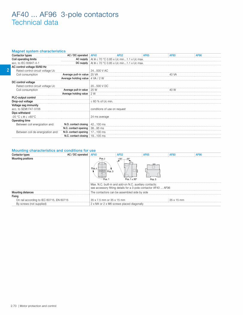
Magnet system characteristicsContactor types AC / DC operated AF40 AF52 AF65 AF80 AF96Coil operating limits AC supply At θ ≤ 70 °C 0.85 x Uc min...1.1 x Uc max.acc. to IEC 60947-4-1 DC supply At θ ≤ 70 °C 0.85 x Uc min...1.1 x Uc max.AC control voltage 50/60 Hz
Rated control circuit voltage Uc 24...500 V ACCoil consumption Average pull-in value 25 VA 40 VA
Average holding value 4 VA / 2 WDC control voltage
Rated control circuit voltage Uc 20...500 V DCCoil consumption Average pull-in value 25 W 40 W
Average holding value 2 WPLC-output control -Drop-out voltage ≤ 60 % of Uc min.Voltage sag immunityacc. to SEMI F47-0706 conditions of use on requestDips withstand-20 °C ≤ θ ≤ +60°C 24 ms averageOperating time
Between coil energization and: N.O. contact closing 42...100 msN.C. contact opening 38...95 ms
Between coil de-energization and: N.O. contact opening 17...100 msN.C. contact closing 19...105 ms
AF40 ... AF96 3-pole contactorsTechnical data
Mounting characteristics and conditions for useContactor types AC / DC operated AF40 AF52 AF65 AF80 AF96Mounting positions
Pos. 5
Pos. 3
Pos. 2
Pos. 1 Pos. 1 ± 30°
+30° -30°
Pos. 4
Max. N.C. built-in and add-on N.C. auxiliary contacts: see accessory fitting details for a 3-pole contactor AF40 ... AF96
Mounting distances The contactors can be assembled side by sideFixing
On rail according to IEC 60715, EN 60715 35 x 7.5 mm or 35 x 15 mm 35 x 15 mmBy screws (not supplied) 2 x M4 or 2 x M6 screws placed diagonally
2.74 | Motor protection and control Motor protection and control | 2.75
1
2.74 | Motor protection and control Motor protection and control | 2.75
2
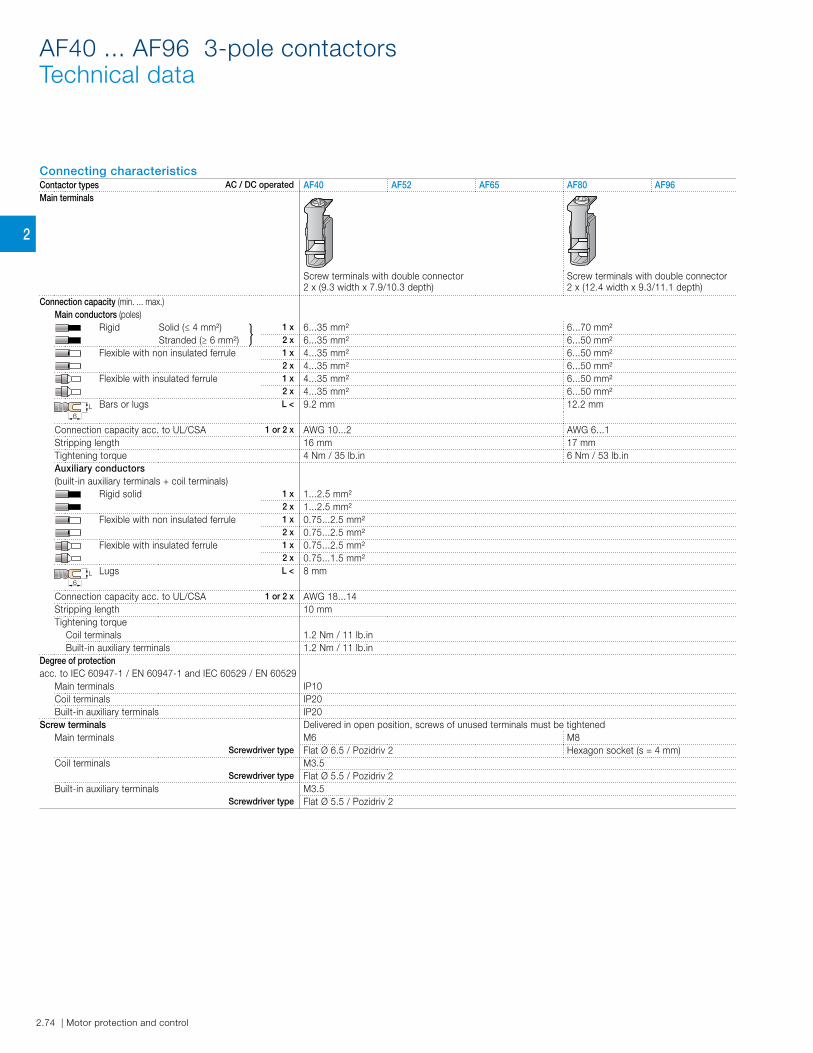
Connecting characteristicsContactor types AC / DC operated AF40 AF52 AF65 AF80 AF96Main terminals
Screw terminals with double connector2 x (9.3 width x 7.9/10.3 depth)
Screw terminals with double connector2 x (12.4 width x 9.3/11.1 depth)
Connection capacity (min. ... max.)Main conductors (poles)
Rigid Solid (≤ 4 mm²) 1 x 6...35 mm² 6...70 mm²Stranded (≥ 6 mm²) 2 x 6...35 mm² 6...50 mm²
Flexible with non insulated ferrule 1 x 4...35 mm² 6...50 mm²2 x 4...35 mm² 6...50 mm²
Flexible with insulated ferrule 1 x 4...35 mm² 6...50 mm²2 x 4...35 mm² 6...50 mm²
L6
Bars or lugs L < 9.2 mm 12.2 mm
Connection capacity acc. to UL/CSA 1 or 2 x AWG 10...2 AWG 6...1Stripping length 16 mm 17 mmTightening torque 4 Nm / 35 lb.in 6 Nm / 53 lb.inAuxiliary conductors(built-in auxiliary terminals + coil terminals)
Rigid solid 1 x 1...2.5 mm²2 x 1...2.5 mm²
Flexible with non insulated ferrule 1 x 0.75...2.5 mm²2 x 0.75...2.5 mm²
Flexible with insulated ferrule 1 x 0.75...2.5 mm²2 x 0.75...1.5 mm²
L6
Lugs L < 8 mm
Connection capacity acc. to UL/CSA 1 or 2 x AWG 18...14Stripping length 10 mmTightening torque
Coil terminals 1.2 Nm / 11 lb.inBuilt-in auxiliary terminals 1.2 Nm / 11 lb.in
Degree of protection acc. to IEC 60947-1 / EN 60947-1 and IEC 60529 / EN 60529
Main terminals IP10Coil terminals IP20Built-in auxiliary terminals IP20
Screw terminals Delivered in open position, screws of unused terminals must be tightenedMain terminals M6 M8
Screwdriver type Flat Ø 6.5 / Pozidriv 2 Hexagon socket (s = 4 mm)Coil terminals M3.5
Screwdriver type Flat Ø 5.5 / Pozidriv 2Built-in auxiliary terminals M3.5
Screwdriver type Flat Ø 5.5 / Pozidriv 2
AF40 ... AF96 3-pole contactorsTechnical data
2.92 | Motor protection and control Motor protection and control | 2.93
1
2.92 | Motor protection and control Motor protection and control | 2.93
2
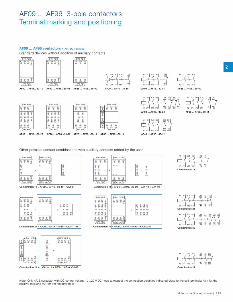
AF09 ... AF16..-30-10
AF09 ... AF96..-30-22
AF40 ... AF96..-30-11
AF09 ... AF16..-30-01 AF26 ... AF96..-30-00
AF26 ... AF38..-30-11
AF09 ... AF16..-30-01
AF26 ... AF38..-30-11
AF26 ... AF96..-30-00
AF40 ... AF96..-30-11
AF09 ... AF16..-30-10
AF09 ... AF16..-30-22
Combination 11 = AF09 ... AF16..-30-10 + CA4-01
Combination 21 = AF09 ... AF16..-30-10 + CAT4-11M Combination 32 = AF09 ... AF16..-30-10 + CA4-22M
Combination 11 = AF26 ... AF96..-30-00 + CA4-10 + CA4-01
Combination 21
Combination 32
Combination 21
Combination 11
Combination 21 = CAL4-11 + AF09 ... AF16..-30-10
13
NO
NO
14
5L3
6T3
3L2
4T2
1L1
2T1
A1 A2
A1 A2
21
NC
NC
22
5L3
6T3
3L2
4T2
1L1
2T1
A1 A2
A1 A2
5L3
6T3
3L2
4T2
1L1
2T1
A1 A2
A1 A2
5L33L2A1
A2 6T34T2
1L1
2T1
13NO
NO14
5L33L2A1
A2 6T34T2
1L1
2T1
21NC
NC22
5L33L2A1
A2 6T34T2
1L1
2T1
= +
-1
NC
-2
13
NO
14
5L3
6T3
3L2
4T2
1L1
NO
2T1
21
NC
22
A1 A2
A1 A2
A1 A2
2-
2-
13
NO
5L33L21L1
146T34T2
NO
2T1
A1 A2
= + +
-3
NO
-4
-1
NC
-2
5L3
6T3
3L2
4T2
1L1
13
NO
2T1
14
A1 A2
21
NC
22
A1 A2
A1 A2
1-
1-
2-
2-
5L33L21L1
6T34T22T1
A1 A2
= +
A1 21
NC
22
33
NO
34 A2
13
NO
5L33L21L1
146T34T2
NO
2T1
13
NO
14
5L3
6T3
3L2
4T2
1L1
A1
NO
2T1
21
NC
22
33
NO
34 A2
= +
13
NO
14
5L3
6T3
3L2
4T2
1L1
NO
2T1
A1 A2
31
NC
32
21
NC
22
43
NO
44
53
NO
54
21 31
NCNC
3222
43 53
NO NO
44 54
A1 A2
A1 A2
13
NO
5L33L21L1
146T34T2
NO
2T1
A1 A2
= +
13X
NO
21X
NC
NO
14X
NC
22X
13X
NO
21X
NC
NO
14X
NC
22X
13
NO
NO
14
5L3
6T3
3L2
4T2
1L1
2T1
A1 A2
A1 A2
13
NO
NO
14
5L3
6T3
3L2
4T2
1L1
2T1
A1 A2
A1 A2
21NC
NC22
5L33L2A1
A2 6T34T2
1L1
2T1
13NO
NO14
21NC
NC22
5L33L2A1
A2 6T34T2
1L1
2T1
13NO
NO14
33NO
NO34
21NC
NC22
5L33L2A1
A2 6T34T2
1L1
2T1
13NO
NO14
43NO
NO44
53NO
NO54
31NC
NC32
13XNO
NO14X
21XNC
NC22X
5L33L2A1
A2 6T34T2
1L1
2T1
13NO
NO14
Note: Only AF..Z contactor with DC control voltage 12...20 V DC need to respect the connection polarities indicated close to the coil terminals: A1+ for the positive pole and A2- for the negative pole
5L3
6T3
3L2
4T2
1L1
43
NO
31
NC
21
NC
13
NO
2T1
44322214
A1 A2
A1 A2
5L3
6T3
3L2
4T2
1L1
21
NC
13
NO
2T1
2214
A1 A2
A1 A2
21NC
NC22
5L33L2A1
A2 6T34T2
1L1
2T1
13NO
NO14
43NO
NO44
31NC
NC32
21NC
NC22
5L33L2A1
A2 6T34T2
1L1
2T1
13NO
NO14
13XNO
NO14X
21XNC
NC22X
5L33L2A1
A2 6T34T2
1L1
2T1
13X
NO
21X
NC
NO
14X
NC
22X
6T3
3L2
4T2
1L1
2T1
A1 A2
A1 A2
5L3
AF26 ... AF96..-30-22
5L3
6T3
3L2
4T2
1L1
43
NO
31
NC
21
NC
13
NO
2T1
44322214
A1 A2
A1 A2
AF09 ... AF96 3-pole contactorsTerminal marking and positioning
AF09 ... AF96 contactors - AC / DC operated Standard devices without addition of auxiliary contacts
Other possible contact combinations with auxiliary contacts added by the user