aerospace sealing systems - all seals inc
TRANSCRIPT

Aerospacesealing systems
Your Partner for Sealing Technology

Aerospace Engineering Guide
1
Busak+ ShambanEdition April 2004
Contents
Sealing System Examples 3. . . . . . . . . . . . . . . . . . . . . . . . . . . . . . . . . . . . . . . . . . . . . . . . . . . . . . . . . . . . . . . . . . . . .
TurconR Seal Materials 11. . . . . . . . . . . . . . . . . . . . . . . . . . . . . . . . . . . . . . . . . . . . . . . . . . . . . . . . . . . . . . . . . . . . .
TurelR Elastomer Materials 14. . . . . . . . . . . . . . . . . . . . . . . . . . . . . . . . . . . . . . . . . . . . . . . . . . . . . . . . . . . . . . . . . .
Aerospace Hydraulic Fluids 16. . . . . . . . . . . . . . . . . . . . . . . . . . . . . . . . . . . . . . . . . . . . . . . . . . . . . . . . . . . . . . . . . . .
Surface Finish (Recommendations) 17. . . . . . . . . . . . . . . . . . . . . . . . . . . . . . . . . . . . . . . . . . . . . . . . . . . . . . . . . . . . .
Surface Finish (Measurement Methods) 21. . . . . . . . . . . . . . . . . . . . . . . . . . . . . . . . . . . . . . . . . . . . . . . . . . . . . . . . .
Hardware Specifications 24. . . . . . . . . . . . . . . . . . . . . . . . . . . . . . . . . . . . . . . . . . . . . . . . . . . . . . . . . . . . . . . . . . . . .
FEA Analyses 28. . . . . . . . . . . . . . . . . . . . . . . . . . . . . . . . . . . . . . . . . . . . . . . . . . . . . . . . . . . . . . . . . . . . . . . . . . . . . . .
Seal Quick Reference Guide 29. . . . . . . . . . . . . . . . . . . . . . . . . . . . . . . . . . . . . . . . . . . . . . . . . . . . . . . . . . . . . . . . . .
Selection Criteria for Aerospace Seals 30. . . . . . . . . . . . . . . . . . . . . . . . . . . . . . . . . . . . . . . . . . . . . . . . . . . . . . .
Hardware Dimensions per MIL-G-5514F and AS4716, Bore 36. . . . . . . . . . . . . . . . . . . . . . . . . . . . . . . . . . . . . . .
Hardware Dimensions per MIL-G-5514F and AS4716, Rod 40. . . . . . . . . . . . . . . . . . . . . . . . . . . . . . . . . . . . . . .
TurconR VL SealR 44. . . . . . . . . . . . . . . . . . . . . . . . . . . . . . . . . . . . . . . . . . . . . . . . . . . . . . . . . . . . . . . . . . . . . . . .
TurconR Plus SealRII 50. . . . . . . . . . . . . . . . . . . . . . . . . . . . . . . . . . . . . . . . . . . . . . . . . . . . . . . . . . . . . . . . . . . . . .
TurconR Double DeltaRII 54. . . . . . . . . . . . . . . . . . . . . . . . . . . . . . . . . . . . . . . . . . . . . . . . . . . . . . . . . . . . . . . . . .
TurconR WedgpakR 56. . . . . . . . . . . . . . . . . . . . . . . . . . . . . . . . . . . . . . . . . . . . . . . . . . . . . . . . . . . . . . . . . . . . . .
TurconR HatsealRII 59. . . . . . . . . . . . . . . . . . . . . . . . . . . . . . . . . . . . . . . . . . . . . . . . . . . . . . . . . . . . . . . . . . . . . . .
TurconR T-Seal 62. . . . . . . . . . . . . . . . . . . . . . . . . . . . . . . . . . . . . . . . . . . . . . . . . . . . . . . . . . . . . . . . . . . . . . . . . .
TurconR AQ-SealR5 (For use in MIL-Standard Grooves) 65. . . . . . . . . . . . . . . . . . . . . . . . . . . . . . . . . . . . . . . .
TurconR VarisealR 68. . . . . . . . . . . . . . . . . . . . . . . . . . . . . . . . . . . . . . . . . . . . . . . . . . . . . . . . . . . . . . . . . . . . . . . .
TurconR Back-up Ring (BUR) 79. . . . . . . . . . . . . . . . . . . . . . . . . . . . . . . . . . . . . . . . . . . . . . . . . . . . . . . . . . . . . . .
Seals manufactured to MIL-G-5514F (Rod and Bore Sizes Only)
TurconR Dual Piston Ring 82. . . . . . . . . . . . . . . . . . . . . . . . . . . . . . . . . . . . . . . . . . . . . . . . . . . . . . . . . . . . . . . . . .
TurconR Glyd RingR - For use with MIL-G-5514F/AS4716 Rod/Bore 85. . . . . . . . . . . . . . . . . . . . . . . . . . . . .
TurconR StepsealRK 91. . . . . . . . . . . . . . . . . . . . . . . . . . . . . . . . . . . . . . . . . . . . . . . . . . . . . . . . . . . . . . . . . . . . . .
TurconR Roto Glyd RingR - For use with MIL-G-5514F/AS4716 Rod/Bore 98. . . . . . . . . . . . . . . . . . . . . . . . .
TurconR VarilipR 100. . . . . . . . . . . . . . . . . . . . . . . . . . . . . . . . . . . . . . . . . . . . . . . . . . . . . . . . . . . . . . . . . . . . . . . . .
Seals for Boeing Gland Standard BACS11AA 102. . . . . . . . . . . . . . . . . . . . . . . . . . . . . . . . . . . . . . . . . . . . . . . . . . . .
Footseal II 103. . . . . . . . . . . . . . . . . . . . . . . . . . . . . . . . . . . . . . . . . . . . . . . . . . . . . . . . . . . . . . . . . . . . . . . . . . . . . . .

Aerospace Engineering Guide
2
Busak+ Shamban Edition April 2004
Selection of the Scraper Element 104. . . . . . . . . . . . . . . . . . . . . . . . . . . . . . . . . . . . . . . . . . . . . . . . . . . . . . . . . . . . . .
TurconR DC Scraper Ring 105. . . . . . . . . . . . . . . . . . . . . . . . . . . . . . . . . . . . . . . . . . . . . . . . . . . . . . . . . . . . . . . . .
TurconR ExcluderRDC, Series E 106. . . . . . . . . . . . . . . . . . . . . . . . . . . . . . . . . . . . . . . . . . . . . . . . . . . . . . . . . . . .
TurconR ExcluderRDC 107. . . . . . . . . . . . . . . . . . . . . . . . . . . . . . . . . . . . . . . . . . . . . . . . . . . . . . . . . . . . . . . . . . . .
TurconR VarisealRM2S Scraper 111. . . . . . . . . . . . . . . . . . . . . . . . . . . . . . . . . . . . . . . . . . . . . . . . . . . . . . . . . . . . .
TurciteR SlydringR/LuytexR SlydringR 114. . . . . . . . . . . . . . . . . . . . . . . . . . . . . . . . . . . . . . . . . . . . . . . . . . . . . . . . . .
TurconR WedgpakR Face Seal 118. . . . . . . . . . . . . . . . . . . . . . . . . . . . . . . . . . . . . . . . . . . . . . . . . . . . . . . . . . . . . . .
Installation Instructions 123. . . . . . . . . . . . . . . . . . . . . . . . . . . . . . . . . . . . . . . . . . . . . . . . . . . . . . . . . . . . . . . . . . . . . . .
Quality Criteria 127. . . . . . . . . . . . . . . . . . . . . . . . . . . . . . . . . . . . . . . . . . . . . . . . . . . . . . . . . . . . . . . . . . . . . . . . . . . . .
Storage 128. . . . . . . . . . . . . . . . . . . . . . . . . . . . . . . . . . . . . . . . . . . . . . . . . . . . . . . . . . . . . . . . . . . . . . . . . . . . . . . . . . .
Customer Approvals 129. . . . . . . . . . . . . . . . . . . . . . . . . . . . . . . . . . . . . . . . . . . . . . . . . . . . . . . . . . . . . . . . . . . . . . . . .
Technical Questionaire 131. . . . . . . . . . . . . . . . . . . . . . . . . . . . . . . . . . . . . . . . . . . . . . . . . . . . . . . . . . . . . . . . . . . . . . .
Aerospace Engineering Guide
3
Busak+ ShambanEdition April 2004
Sealing System Examples
Typical Hydraulic Equipment using Shamban Systems
In each individual case the type of system should be selectedbased on criteria such as friction, leakage, and cost. In thefollowing examples we have mentioned the main features foreach system as a guideline; however, the section describingthe individual product should always be consulted to ensurethat all operational requirements are fulfilled.
Utility Actuator Systems: Rod Applications
For general purpose hydraulic actuators, Shambanoffers a variety of simple and reliable sealing systems:
TurconR
ExcluderRDCTurconR
WedgpakR
p
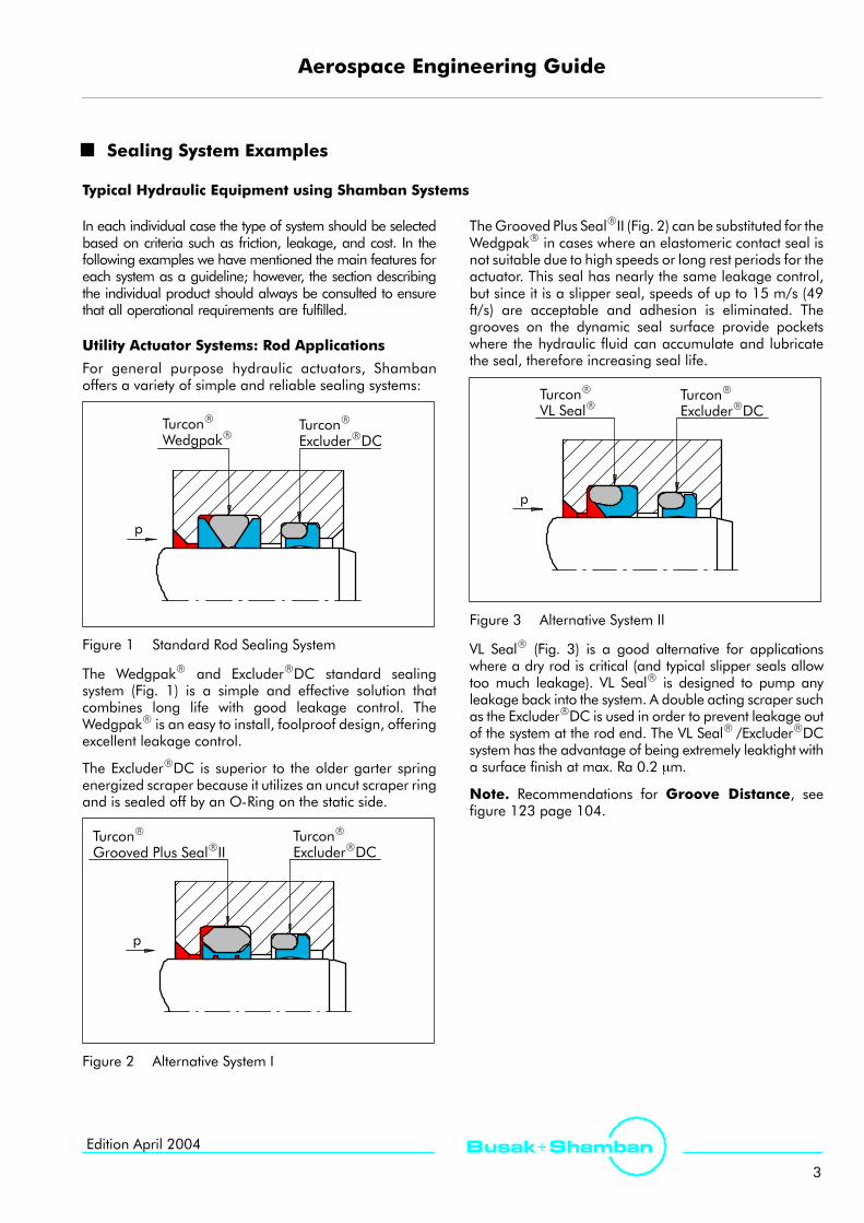
Figure 1 Standard Rod Sealing System
The WedgpakR and ExcluderRDC standard sealingsystem (Fig. 1) is a simple and effective solution thatcombines long life with good leakage control. TheWedgpakR is an easy to install, foolproof design, offeringexcellent leakage control.
The ExcluderRDC is superior to the older garter springenergized scraper because it utilizes an uncut scraper ringand is sealed off by an O-Ring on the static side.
TurconR
ExcluderRDCTurconR
Grooved Plus SealRII
p
Figure 2 Alternative System I
TheGrooved Plus SealRII (Fig. 2) can be substituted for theWedgpakR in cases where an elastomeric contact seal isnot suitable due to high speeds or long rest periods for theactuator. This seal has nearly the same leakage control,but since it is a slipper seal, speeds of up to 15 m/s (49ft/s) are acceptable and adhesion is eliminated. Thegrooves on the dynamic seal surface provide pocketswhere the hydraulic fluid can accumulate and lubricatethe seal, therefore increasing seal life.
TurconR
ExcluderRDC
p
TurconR
VL SealR
Figure 3 Alternative System II
VL SealR (Fig. 3) is a good alternative for applicationswhere a dry rod is critical (and typical slipper seals allowtoo much leakage). VL SealR is designed to pump anyleakage back into the system. A double acting scraper suchas the ExcluderRDC is used in order to prevent leakage outof the system at the rod end. The VL SealR /ExcluderRDCsystem has the advantage of being extremely leaktight witha surface finish at max. Ra 0.2 µm.
Note. Recommendations for Groove Distance, seefigure 123 page 104.

Aerospace Engineering Guide
4
Busak+ Shamban Edition April 2004
Utility Actuator Systems: Piston Applications
Piston systems are typically simpler than rod systems.They must be of symetrical design to cope with thechanging direction of the fluid pressure.
TurconR Dual Piston Ring
p p
Figure 4 TurconR Dual Piston Ring
Where controlled leakage is permissible, the Dual PistonRing offers a good, reliable, low friction seal in a narrowgroove width.
p p
TurconR
Grooved Plus SealRII
Figure 5 TurconR Grooved Plus SealRII
Where leakage is critical, the Grooved Plus SealRII iswidely used and has excellent wear characteristics.
TurconR Glyd RingR
p p
Figure 6 TurconR Glyd RingR
The TurconR Glyd RingR is a simple, reliable and cost-effective slipper seal that is worthwhile considering as analternative to the Plus SealRII if MIL-G-5514F glanddesign is not mandatory.
p
TurconR WedgpakR
p
Figure 7 TurconR WedgpakR
The Wedgpak is a ”zero” leakage elastomer contact sealwith outstanding dynamic performance and easyinstallation.

Aerospace Engineering Guide
5
Busak+ ShambanEdition April 2004
Advanced Actuator Systems:Primary Flight ControlsRod Applications with Dual Unvented Seals
With the increased use of fly-by-wire technology, mostprimary flight controls use a dual unvented sealing system inorder to meet the high performance and long liferequirement.
TurconR
ExcluderRDC
p
TurconR
VL SealR
Figure 8 High Frequency System
The tandem VL SealR combines the low frictioncharacteristics of the slipper seal with a leaktightperformance. The dual edge ExcluderRDC closes theleakage by low pressure and static stand-by operations.
Although the HatsealRII and the WedgpakR have beenused for many years for high frequency systems, thetandemVL SealR system provides increased reliability andcan survive high frequency dither stroke applications withincreased service life.
Rod Applications with Pressure Relieving Seals
In some cases an interstage pressure build-up can beexperienced in a dual unvented sealing system. The followingfactors are contributing to this phenomenon:
- Stroke frequency- Stroke length- Pressure variation- Extrusion gap- Surface finish- Oil viscosity- TemperatureThe following systems are designed to allow the interstagepressure build-up to be relieved back into the system , whenthe system pressure drops or in the case of the StepsealRKduring the retract stroke of the rod.
TurconR
ExcluderRDC
p
TurconR
Plus SealRPRTurconR
WedgpakR
Figure 9 System with Pressure Relieving Plus SealRPR
The Plus SealRPR is capable of relieving any interstagepressure.
The Plus SealRPR is easily fitted into existing grooves as aretrofit if a pressure build-up is noticed, requires a carefulinstallation.
TurconR
VL SealRTurconR
ExcluderRDC
p
TurconR
WedgpakR
Figure 10 System with Pressure Relieving VL SealR
Pressure relieving can also be achieved by using theVL SealR as a primary seal. The sealing lip will lift if theback pressure exceeds approximately 10 bars (145 psi).
VL SealR/WedgpakR configuration offers the optimumpressure relieving seal system, due to the VL SealR design.Pressure trapped in between the two seals is preventedfrom leaking through by the elastomer contact of theWedgpakR and the slight tilt of the VL SealR caused bybackpressure, allowing the oil back into the circuit.
Aerospace Engineering Guide
6
Busak+ Shamban Edition April 2004
Advanced Actuator Systems, i.e.:Primary Flight ControlsPiston Applications
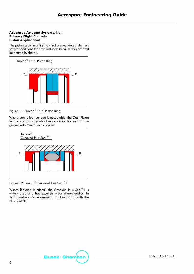
The piston seals in a flight control are working under lesssevere conditions than the rod seals because they are welllubricated by the oil.
TurconR Dual Piston Ring
p p
Figure 11 TurconR Dual Piston Ring
Where controlled leakage is acceptable, the Dual PistonRing offers a good reliable low friction solution in a narrowgroove with minimum hysteresis.
p p
TurconR
Grooved Plus SealRII
Figure 12 TurconR Grooved Plus SealRII
Where leakage is critical, the Grooved Plus SealRII iswidely used and has excellent wear characteristics. Inflight controls we recommend Back-up Rings with thePlus SealRII.

Aerospace Engineering Guide
7
Busak+ ShambanEdition April 2004
Landing Gear Shock Struts
TurconR
ExcluderRDC
TurconR
HatsealRII
p
TurciteR
SlydringR
Figure 13 Small Diameter Shock Strut
For smaller diameter shock struts, the HatsealRII/ExcluderRDC has proven to be a cost effective solutiondue to the long service life.
p
TurconR
ExcluderRDCTurconR
HatsealRIITurciteR
SlydringRTurconR
WedgpakRLuytexR
SlydringRLuytexR
SlydringR
Figure 14 Large Landing Gear with Installed Spare Seal
For medium sized landing gear, it is an advantage to usea tandem sealing system with by-pass around the inboardseal. This means that initially the pressure drop is over theoutboard seal, and the inboard seal runs in a lubricatedenvironment. When a leakage is detected, the by-passcan be closed and operations continue on the inboardseal until the next scheduled overhaul.
On landing gears where severe shock strut deflection canbe expected, the use of SlydringR is recommended toavoid scoring caused by metal-to-metal contact of themoving parts.
p
TurconR
ExcluderRDCTurciteR
SlydringRTurconR DeltaPlus SealRII
LuytexR
SlydringRLuytexR
SlydringR
Figure 15 Large Diameter Shock Struts
For large diameter landing gear where heavydeformations and high pressure shocks may occur, it isessential to use a slipper seal without elastomer contact to
provide the necessary service life. The use of LuytexR
SlydringR are critical to good performance becausemetal-to-metal contact is avoided.

Aerospace Engineering Guide
8
Busak+ Shamban Edition April 2004
TurconR
VL SealR
p
TurconR
ExcluderRDCLuytexR
SlydringRTurciteR
SlydringR
TurconR
HatsealR
Figure 16 Future Landing Gear Sealing System
Tandem sealing systems represent the ultimate sealingsolution for landing gear, with the new Series 600 crosssection, and there is room for it. The TurconR VL SealR asthe primary seal to take up the peak and pulsationpressure, protecting the TurconR HatsealRII as theleaktight performer with the lip. Both seal designs areconsidered the superior strut seals and the combinationof the seal designs will only improve the performance.
Shamban seals and bearings are among othersused for the following Landing Gearapplications:
A320, A380/340B737, B747, B757 and B767,ATP, F-5, Eurofighter, J31, HS748, Spitfire, EMB 145, PC7and PC9.
Rotary Vane Sealing SystemA rotary vane sealing system consists of a rectangularcap seal with a centerplate, and an O-Ring to energizeand seal between the chambers. The corner seal can bedesigned in various shapes to control the leakpathbetween chambers and rod. The TurconR WedgpakR
is positioned as rotary seal with a small elastomercontact to prevent leakage even at low pressure. Finally
the ExcluderRDC prevents contamination from enteringthe system. If space is available, a SlydringR isrecommended between the rod seal and theExcluderRDC.
Please consult your Shamban sales engineer for furtherrecommendations.
Vane SealCorner Seal
TurconR
WedgpakR
TurconR
ExcluderR DC,Series E
A
ASection A - A
Figure 17 Rotary Actuator Sealing System

Aerospace Engineering Guide
9
Busak+ ShambanEdition April 2004
Accumulators
The TurconR AQ-SealR5 is a leak-tight, long-lasting piston seal. The use of SlydringR is recommended to avoid leakageresulting from piston misalignment with the bore.
TurconR
AQ-SealR5
Oil N 2
TurciteR
SlydringR
Figure 18 Accumulator Sealing Systems. Application Example: Sikorsky H60
Spool Valves
Reduced gland width can be achieved by using a TurconR Glyd RingR internally, and a TurconR WedgpakR withelastomer contact to prevent external leakage.
TurconR
Glyd RingRTurconR
WedgpakR
Figure 19 Spool Valve Sealing Systems. Application Example: IPTN

Aerospace Engineering Guide
10
Busak+ Shamban Edition April 2004
BrakesBrake pistons equipped with a spring energized TurconR
VarisealRH to take pressure and temperature variation,combined with the tight and efficientTurconRExcluderRDC, Series E, have proven to be veryreliable. The advantage of using VarisealR (springenergized TurconR jackets) instead of elastomer contactor energized seals is that brake systems often exceed the
temperature capability of the elastomer. Springenergized seals can go from -100_C/-148_F to+260_C/500_F, and metallic springs address most fluidcompatility problems.
The Spring Liner protects the brake housing from wearand abrasion from the spring.
p
TurconR VarisealRH TurconR ExcluderRDC
TurconR Concave Ring
TurconR Spring Liner
p
Figure 20 Brake Sealing System. Application Example: F-16 A/B
Aerospace Engineering Guide
11
Busak+ ShambanEdition April 2004
TurconR Seal Materials
TurconR materials are carefully formulated proprietaryblends and are based on premium-grade PTFEfluoropolymer resins. Fillers are added that improve sealmaterial properties. Fillers improve wear extrusion,resistance and high-temperature properties of TurconR.The key features of TurconR seal materials are as follows:
Low Friction
TurconRmaterials exhibit the lowest coefficient of frictionof any known solid, as low as 0.04 unlubricated onpolished steel. The friction values obtained underlubricated conditions will be smaller. A unique propertyis the very low static coefficient of friction of TurconR
which results in extremely low breakout friction. TurconR
materials do not adhere to their mating surfaces,therefore eliminating any worries about stick-slip indynamic applications.
Chemical Compatibility
TurconR materials are chemically inert in essentially allindustrial chemicals and solvents, even at elevatedtemperatures and pressures. A single TurconR materialcan handle an extremely wide range of solvents, acids, orother corrosive media.
Temperature Range
TurconR materials can operate at service temperaturesfrom -196_C /320_F up to 260_C /500_F, (even furtherunder special conditions) but it is necessary to limit otherworking conditions, such as speed and pressure, whenthe temperature reaches the limit.
Temperature Cycling
In elastomeric seals, temperature cycling causesmaterial degradation leading to compression-set of theelastomer. TurconRmaterial properties, however, are notaltered by cycling temperatures. TurconR also does notcontain plasticizers or any other ingredients which coulddegrade at temperatures below 300_C (572_F).
High Surface Speed
TurconR materials generate far less heat than othermaterials, such as elastomer, polyurethane, etc. Ingeneral, surface speed can go up to 15 m/s, dependingupon seal design and working conditions. Speedexceeding 20 m/s has been achieved under specialconditions.
Aging
TurconR properties do not significantly change overtime. TurconR does not age and will not embrittle ordegrade when exposed to severe-weatheringconditions of heat, light, water, salt spray, etc. This isuseful when seals might sit idle for years and still berequired to perform with complete reliability.
Resilience
TurconRmaterials may experience ”cold flow” or creepunder continued thermal or mechanical stress becausethey do not have the resilience of elastomers.Consequently, TurconR materials require anexternal-loading device such as a metal spring or anelastomer. This is required to provide the radial forcewhich compensates for seal wear, cold flow, and thenormal variations in gland dimensions due totolerances or eccentricity.
Wear Resistance
TurconR materials are formulated to enhance wear lifeat high speeds, pressures, and temperatures throughthe addition of fillers such as carbon fiber, glass fiber,molybdenum disulphide and others. TurconRmaterialsachieve wear values that exceed the demands of manydifficult sealing environments.
Radiation
TurconR is not recommended for an accumulatedradiation dose above 7 x 10² Gy (7 x 10⁴ rad). The largeflourine molecules in the PTFE chain make good targetsfor radioactive particles. The molecular-chain structure isdamaged by scissure when exposed to radiation, resultingin lowered tensile strength and eventual disintegration. Inhigh-radiation service, other fluoropolymers such as EFTEand PCTFE or ZurconR materials are recommended.
Polytetrafluoroethylene (PTFE) Properties
Since TurconRmaterials are based on premium-grade PTFEresins, the general properties of PTFE may be of furtherinterest. PTFE has excellent electric properties such as a lowdielectric constant and a very high dieletric strength, even atelevated temperatures. PTFE will not sustain fire in pureoxygen. Virgin PTFE is physiologically inert.
The water absorption of PTFE is 0.01%. PTFE does notabsorb fluid to a level worth mentioning other thanfluorinated-cooling media (e.g. Freon). Fluorinated fluidscan cause a reversible weight increase of approximately5% accompanied by dimensional increases ofapproximately 1%.

Aerospace Engineering Guide
12
Busak+ Shamban Edition April 2004
Material Data
All TurconRMaterials are made of a high grade composition of Polytetrafluoroethylene (PTFE) resin and processed in anisostatic molding process.The following list includes the standard TurconR materials, but a large number of other materials are available and willbe specified when required by the working conditions. The materials are tested at 23_C (73.4_F)
Table I TurconR Materials
MaterialCode
Description and
Tensile StrengthElonga-tion atbreak
SpecificGravity Hardness
TurconR
Description andrecommended use Color ASTM
D4894[MPa]
ASTMD
4894[psi]
ASTMD
4894[%]
ASTMD792
[g/cm3]
ASTMD
2240[Shore D]
T01Virgin, exceeding MIL-R-8791Profile: Clean system, low friction and pressureSurface: Steel and chrome
Whiteto
Off-white42.3 6130 378 2.16 58
T05
TurconR.Profile: All systems, low friction, medium lifetime andpressureSurface: Steel and chrome
Turquoise 39.2 5682 392 2.17 57
T10*Additive: Carbon and graphiteProfile: Dry system, poor lubrication. Large extrusion gapSurface: Steel, chrome
Black 21.9 3180 183 2.05 64
T19Additive: Mineral fibers and MoS2Profile: High pressure and long wear lifeSurface: Steel, chrome and ceramic
Gray 24.2 3506 226 2.30 63
T25Additive: Glass fibers and MoS2Profile: Rotary applicationSurface: Hardened steel, chrome and ceramic
Gray 31.5 4562 286 2.23 59
T29Additive: Carbon fibers high filledProfile: Long wearlife and large extrusion gapSurface: Steel and chrome
Gray 22.1 3208 217 2.01 61
T40Additive: Carbon fibers medium filledProfile: Long wearlifeSurface: Aluminum, Steel and chrome
Gray 24.7 3579 241 2.06 60
T47Additive: Bronze medium filledProfile: Bearing and SlydringRSurface: Steel and chrome
Lightto
dark brown27.6 4000 250 3.09 60
T49Additive: Bronze medium filled acid treatedProfile: Extrusion resistantSurface: Hardened steel and chrome
Gray 27.6 4000 250 3.10 63
T99Additive: MoS2Profile: Low friction, medium pressure, long seal lifeSurface: Steel, chrome and anodized aluminum
Gray 37.2 5385 347 2.22 58
Note ! The values in Table I are nominals, intended for engineering reference only. These values are not to be usedas a specification requirement. Specification values are available upon request.
* TurconR T11, used in North America is equivalent to TurconR T10.

Aerospace Engineering Guide
13
Busak+ ShambanEdition April 2004
Table II ZurconR Materials
MaterialCode
D i i C l
Tensile Strength Elongationat break
SpecificGravity Hardness
R
Description Color ASTM D 638 ASTM D 638 ASTM D 792 ASTM D 785ZurconR [MPa] [psi] [%] [g/cm3] [Shore R]
Z48Proprietary PolyesterLeaktight performanceSteel and chrome (Formerly ZurconR 448)
Uniformblack 44.1 6.400 550 1.20 -
Z60Polyamide and MoS2Spec. T-Seal and corner reinforcementSteel and chrome (Formerly HiModR 60)
Gray 82.7 12.000 50 1.16 120
ZurconRASTMD 1457[MPa]
ASTMD 1457[psi]
ASTM D 1457[%]
ASTM D 621(Deformation@ 2.000 psi73_F/24 hrs)
ASTM D 785[M Scale]
Z43
High modulus thermo plastics + PTFE + CarbonBearing, StakbakR and corner reinforcementSteel, chrome and ceramic(Formerly HiModR 552)
Uniformblack 81.0 11.750 25 0.08% 95
Note: The testing of tensile properties are based on the microtensile specimen per ASTMD 1457/D 4894, pulled at 2 inches per minute with an initialjaw separation at 0.875.005 inches. Tensile properties are determined in accordance with the procedures described in ASTM D 638.
Note ! The values in Table II are nominals, intended for engineering references only. These values are not to be usedas a specification requirement. Specified values can only be obtained from each batch.

Aerospace Engineering Guide
14
Busak+ Shamban Edition April 2004
TurelR Elastomer Materials
Many of the Shamban seal designs are composite sealswith an elastomer element as an integral part of the seal.For this reason it is very important that we are in controlof such important seal design parameters as elastomerswell, shrinkage during molding, compression set,compatibility and tolerances.
Through extensive testing in our own test laboratory wemake sure that our materials are manufactured to ourspecifications. A number of the materials have also beenapproved for a QPL as part of a US Government supportprogram.
Selection of elastomer material for a hydraulic fluid is acritical issue since the elastomer materials are moresensitive to fluids than other materials. Chemicalreactions and physical behavior can be very damaging ifthe wrong material is selected.
Even though the specifications ensure compatability,different behaviors can result due to the number and typesof additives used in the oil. It may be necessary to conducta soak test at elevated temperature in order to verify theperformance for critical applications. Contact yourShamban sales engineer for assistance.
Following points are important when designing the sealsystem:
Chemical Compatibility
Compability with the most common oil types can be foundin Table IV, page 16. For other medias please contact yourShamban sales engineer. See also note in section below.
Nitrile MIL-P-83461 versus MIL-P-25732C
Due to the chemical composition of the nitriles, it is veryimportant to separate and use them where the functionalbehaviors are optimized.
Compression Set(Static)
Wearlife(Dynamic)
MIL-P-83461(peroxide cured) + -
MIL-P-25732C(sulphur cured) - +
This indicates that dynamic elastomer contact seal shouldbe MIL-P-25732C in order to optimize seal liferequirement.
Temperature Range
Most TurelR materials can be used in MIL-G-5514F typeII systems (-54_C to +135_C / -65_F to -275_F). The lowtemperature dynamic cycling limits vary according toelastomer type.
Shamban offers other TurelR elastomer compounds whichexpand this temperature range. Please refer to Table III onpage 15. The use of spring energized VarisealR canexpand the temperature range even further.
Temperature Cycling
The effect of temperature cycling on elastomeric sealsresults in compression set which means that the elastomermaterial loses its elasticity over time. For TurelRmaterials,this effect is kept to an acceptable minimum if they arewithin the indicated temperatures.
Cold Temperatures
Elastomer materials contract approximately 10 timesmore than steel in cold environments. The materialbecomes stiffer, loses its flexibility and when passing thelower limit it reaches the glass transition stage whereby itbecomes extremely brittle. Physical properties will recoverwhen temperatures go up again. (Increased squeeze canimprove the performance.)
Hot Temperatures
Elastomer materials soften and loose its physicalproperties when passing the upper temperature limit.Physical properties will not recover and it will take apermanent compression set. (Compression set varies withelastomer type).
Surface Speed
The speed of the dynamic surface in contact with anelastomer contact seal should be kept below 3 m/s (9.8 ft/s)to avoid damage to the elastomer.
Aging
The maximum recommended storage time is shown inTable III. This is only valid if the elastomer is stored undercontrolled conditions in light and airtight packaging.

Aerospace Engineering Guide
15
Busak+ ShambanEdition April 2004
Table III TurelR Elastomer Materials
MaterialCode Base Polymer
TemperatureRange Hardness
(Shore A) Fluid Referencespecification
Recommendedshelf life
New OldBase Polymer Range
_C (_F) (Shore A) Fluid specification shelf life
NK BAK Nitrile(NBR)
-54_C to +135_C(-65_F to +275_F) 75 MIL-H-5606 AMS-P-25732
(on QPL) 10 years
NE BAE Nitrile(NBR)
-54_C to +135_C(-65_F to +275_F) 75 MIL-H-83282 AMS-P-83461
(on QPL) 10 years
NG G Nitrile(NBR)
-54_C to +135_C(-65_F to +275_F) 75 MIL-H-5606
MIL-H-83282 AMS-P-25732 10 years
EH H Ethylene Propylene(EP)
-54_C to +149_C(-65_F to +300_F) 80 Phosphate Ester NAS 1613
rev. 2 class 1 10 years
EP EP Ethylene Propylene(EP)
-54_C to +149_C(-65_F to +300_F) 80 Phosphate Ester NAS 1613
rev. 4 (on QPL) 10 years
FT T Fluorocarbon(FKM)
-34_C to +260_C(-30_F to +500_F) 80 MIL-L-7808
MIL-L-23699 AMS-R-834851) 20 years
FL FAL Fluorocarbon(FKM)
-23_C to +204_C(-10_F to +400_F) 90 MIL-L-7808
MIL-L-23699 AMS-7259 20 years
FK FAK Fluorocarbon(FKM)
-23_C to +204_C(-10_F to +400_F) 75 MIL-L-7808
MIL-L-23699 AMS-7276 20 years
LF F Fluorosilicone(FVMQ)
-73_C to +177_C(-100_F to +350_F) 70 Jet fuel AMS-R-259881) 10 years
LA LEA Fluorosilicone(FVMQ)
-57_C to +177_C(-70_F to +350_F) 80 Jet fuel AMS-R-259881) 10 years
1)Meets physical property requirements of applicable specification.Testing to the specification on a lot-by-lot basis available on request at additional cost.Other materials available upon request. Contact your Shamban sales engineer.

Aerospace Engineering Guide
16
Busak+ Shamban Edition April 2004
Aerospace Hydraulic Fluids
Table IV Common Oil Types
Specification Trade name TemperatureRange Type
MostCompatibleElastomer
MIL-H-5606(Nato code H-515) Red oil -54_C to +135_C
-65_F to +275_F
Petroleum based hydraulic oil. Primary military fluid. NBR, Sulphurcured, FKM,FVMQ
MIL-H-83282C(Nato code H-537)
Synth.Red oil
-40_C to +205_C-40_F to +401_F
Synthetic hydrocarbon based hydraulic oil. The fluid hasimproved fire resistance (fire propagation) and shear stability, butreduced low temperature capability.
NBR, peroxidecured, FKM,FVMQ
MIL-PRF-87257(Nato code H-538)
Synth.Red oil
-54_C to +135_C-65_F to +275_F
Synthetic hydrocarbon based hydraulic oil. Similar to above butimproved cold temperature capability
NBR, FKM,FVMQ
AS 1241A-Cl1 Phosphate -54_C to +135_C Phosphate Ester fluid. No fire propagation.Cl1 i l d i fl id Cl2 i hi h d i
EPDMAS 1241A Cl1AS 1241A-Cl2
PhosphateEster
54 C to +135 C-65_F to +275_F
osp a e s e u d No e p opaga oCl1 is low density fluid, Cl2 is high density.
M
MIL-L-7808 Engine lub. oilNominal
-54_C to +150_C-65_F to +300_F
Synthetic oil-ester based lubricant oil(Organic acid ester based)
FKM
MIL-L-23699C Engine lub. oilNominal
-40_C to +204_C-40_F to +400_F
Synthetic based lubricant oil(Organic acid ester based)
FKM
Viscosities of Typical Fluids vs. Temperature
-60 -40 -20 0 20 40 60 80 100 150 200 250 300 350Temperature _F
0.6
0.70.80.91.0
1.5
2.0
3.0
4.0
6.08.010.0
20
50
100200500
1.0002.0005.00010.000
KinemaricViscosity
-Centistokes
Figure 21

Aerospace Engineering Guide
17
Busak+ ShambanEdition April 2004
Surface Finish (Recommendations)
Surface Finish Recommendations
Current industry standards for surface finish range from0.2-0.4 μm Ra (8-16 μin) per Mil-G-5514 to 0.25-0.50μm Ra (10-20 μin) for general applications. Past industryexperience suggested that surfaces smoother than 0.2 μmRa (8 μin) did not allow for ample lubrication of seals,while surfaces rougher than 0.4-0.5 μm Ra (16-20 μin)prematurely wore seals, resulting in short life. With thesurface measuring and finishing equipment availabletoday, surface finishes smoother than the currentstandards have shown to be suitable and can actuallyimprove overall seal performance.
Investigations into surface finish measurement equipmentand capabilities, along with finishing methods, haveresulted in functional seal testing being performed todetermine and verify surface finish recommendations forimproved seal performance. The followingrecommendations are a guide to defining the propersurface finish for dynamic sealing applications:
Ra = 0.1 - 0.2 μm (4 - 8 μin)
Rz = 1.0 μm maximum (40 μin)
Rp = 0.6 μm maximum (24 μin)
tp (Mr) = 50-70% @ depth p = .25Rzrelative to a ref. line c = 5% tp
These general recommendations apply to all types ofsealing surface finishes including plated or coatedsurfaces and bare, hardened metal surfaces.
Additionally, the surface profile should have a”plateaued”appearance as the illustration of Figure 29 shows. Asurface with a high concentration andmagnitude of peakshas been shown to cause excessive seal wear. A surfacerelatively void of peaks but including valleys forlubrication retention is more suitable for sealingapplications.
Direction or ”Lay” of Finish
Each of the many different methods used to obtain aspecific surface finish - turning, grinding honing,ballizing, polishing, etc. - produces a characteristicdirection or ”lay” to the surface. This factor alone can havean effect on sealing performance and wear patterns incertain applications. To obtain the best seal performance,avoid finishing methods which promote the formation ofleak-paths in your application. For example, avoid astrongly axial lay in a reciprocating rod-seal application,or a definite spiral pattern on the shaft in a rotaryapplication. Consult your Shamban sales engineer forfurther information.
Mating Surface Hardness
The hardness of a mating surface affects sealperformance in several ways. A harder material improveswear life by resisting the tendency of seals to damage themating-surface finish. If thematingmaterial is too soft, theseal will burnish or damage the surface. Harder matingsurfaces also allow the user to specify certain tougher,longer-lasting TurconR seal materials (such as Carbonfiber filled T29) which would not be recommended onsofter hardware surfaces. Harder mating surfaces have atendency to lower the running friction of a seal.
A seal will polish its mating surface, especially if it is asofter metal. For example, a reciprocating rod made ofstainless steel with a hardness of 28 to 30 Rockwell C anda finish of Ra 0.6 µmwill generally be polished by the sealto a finish of Ra 0.3 µm or better over a short time. Sealfriction andwear will then decrease accordingly. Materialsthat are harder than 44 Rockwell C do not polish as easily.The abrasive nature of a rough finish can cause excessiveseal wear during the early burn-in period. Therefore, theharder the mating surface, the more important it is to startwith a smooth finish.
Substrates
In most applications an unplated, uncoated shaft is morethan adequate. Typical mating-surface materials arelisted in the Table IX, page 26 and Table X, page 27. Thesematerials (and others not listed) can also act as substratesfor platings or coatings to achieve higher hardness values.An important property to consider in such cases is theability of the substrate to support the plating. For example,when a high-pressure load is exerted on a seal runningagainst a hard-chrome plating supported by a softsubstrate (such as 300 series stainless steel) the platingmay peel or crack and then abrade the seal. A bettersubstrate would be stainless steel Type 440C (hardened to44 Rockwell C) or an alloy steel such as 4340 in thefully-hardened condition.
Platings and Coatings
Seal designs run well against unplated surfaces atmoderate speeds and pressures. In high-speed rotary orhigh-pressure reciprocating service, harder surfaces arepreferred. Several examples of platings and coatings (nota complete list) are given on page 27.
For further advice on platings and coatings, please consultyour Shamban sales engineer.

Aerospace Engineering Guide
18
Busak+ Shamban Edition April 2004
Seal Material
Seal material selection affects mating-surface hardnessrequirements. When an application requires the longestpossible wear life under moderate to severe conditions,the seal material should be one of the harder, highly-filledTurconR blends. For example, TurconR T29 is verywear-resistant but contains carbon fibers that can abradesoft mating surfaces. These materials should only be runagainst materials with hardness values of 45 to 70+Rockwell C.
Supporting Test Data
Functional dynamic seal testing was conducted underdifferent evaluation programs that were designed to studysurface finish effects on seal performance. Various typesof surfaces (coatings) were evaluated throughout thesetests. Not all of the tests were performed utilizing the sameconditions or test seals. Some of the test results andobserved trends relative to surface finish effects on sealperformance are reported here as supporting data.
Functional seal testing utilizing commercially availableinduction-hardened, chrome-plated (IHCP) piston rodmaterial meeting the 0.2-0.4 μm Ra finish requirementhas typically shown much variation in seal performanceresults. Analyzing test results, the test parameters,equipment and methods concluded that the variationswere most likely due to differences in the surface texturesof the test rods.
Further testing using IHCP rods finished to the extremes ofthe 0.2-0.4 Ra requirement confirmed this suspicion. Atest matrix was conducted whereby four combinations offinishes were evaluated: (Ra in μm)
- 0.2 Ra ground
- 0.2 Ra ground, polished
- 0.4 Ra ground
- 0.4 Ra ground, polished
The results of this study were somewhat surprising anduncovered some effects that surface finish can have onseal performance. In general, the polished surfacesperformed better with respect to seal leakage and wear,which was expected. But the polished 0.4 Ra surfacesallowed better seal performance than the 0.2 Ra ground;this result revealed the need for more in-depth studies ofthe effects of surface texture and type. Not only was the0.2-0.4 μm roughness average finish callout inadequate,but the type of finish (ground only vs. ground andpolished) was also significant to seal performance.
A test program was conducted to evaluate proposedimprovements to a standard industrial sealing system fora reciprocating application. A comparison of different
surface finishes was part of this study. The test rods werenot plated; an alloy steel hardened to Rc 36-40 was thetest rodmaterial. For one of the tests, amaximum Rp value(peak height) was set for the test rod in addition to the Racallout. The wear of the primary seal element wasmeasured after 1 million cycles. The seal that ran on themore tightly-controlled surface finish showed a significantadvantage with respect to wear as Figure 22 illustrates.Leakage performance was identical between the two tests.
0
1
2
3
4
Ave.SealRingweightloss(%)
0.72
3.75
0.2-0.3 Ra0.75 Rp Max
0.2 - 0.4 Ra
Figure 22 Seal Wear Comparison
A seal performance evaluation was conducted comparingstandard hard-chrome plate to electroless nickel andtungsten carbide coatings. These coatings were applied toa base material of C1045 steel, induction hardened to40-50 Rc. Both PTFE-contact (slipper seal) andelastomer-contact seals were evaluated under thefollowing test conditions: (Ra in μm)
Pressure : 3000 psi constant
Stroke : 3 inches
Stroke Rate : 1 Hz
Fluid : Mil-H-83282
Duration : 300.000 cycles(TTD 1.8 million inches)
Temperature: 121_C (250 _F)
Test rods were prepared according to the followingdescriptions:
0.15-0.30 Ra standard hard-chrome
0.15-0.30 Ra standard electroless nickel
0.05-0.10 Ra superfinished electroless nickel
0.05-0.10 Ra superfinished tungsten carbide
Aerospace Engineering Guide
19
Busak+ ShambanEdition April 2004
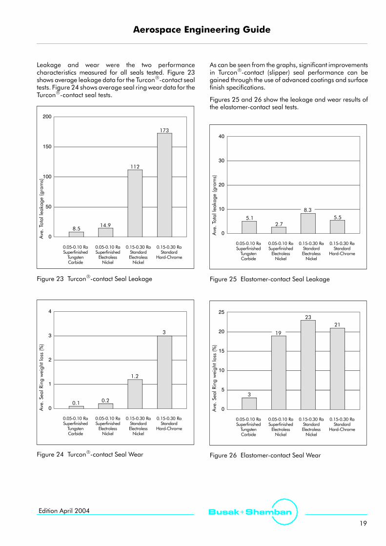
Leakage and wear were the two performancecharacteristics measured for all seals tested. Figure 23shows average leakage data for the TurconR-contact sealtests. Figure 24 shows average seal ringwear data for theTurconR-contact seal tests.
0
50
100
150
200
Ave.Totalleakage(grams)
8.5
173
0.05-0.10 RaSuperfinishedTungstenCarbide
14.9
112
0.05-0.10 RaSuperfinishedElectrolessNickel
0.15-0.30 RaStandardElectrolessNickel
0.15-0.30 RaStandard
Hard-Chrome
Figure 23 TurconR-contact Seal Leakage
0
1
2
3
4
Ave.SealRingweightloss(%)
0.1
3
0.05-0.10 RaSuperfinishedTungstenCarbide
0.2
1.2
0.05-0.10 RaSuperfinishedElectrolessNickel
0.15-0.30 RaStandardElectrolessNickel
0.15-0.30 RaStandard
Hard-Chrome
Figure 24 TurconR-contact Seal Wear
As can be seen from the graphs, significant improvementsin TurconR-contact (slipper) seal performance can begained through the use of advanced coatings and surfacefinish specifications.
Figures 25 and 26 show the Ieakage and wear results ofthe elastomer-contact seal tests.
0
10
20
30
40
5.1 5.5
0.05-0.10 RaSuperfinishedTungstenCarbide
2.7
8.3
0.05-0.10 RaSuperfinishedElectrolessNickel
0.15-0.30 RaStandardElectrolessNickel
0.15-0.30 RaStandard
Hard-Chrome
Ave.Totalleakage(grams)
Figure 25 Elastomer-contact Seal Leakage
0
5
10
15
20
25
Ave.SealRingweightloss(%)
3
21
0.05-0.10 RaSuperfinishedTungstenCarbide
23
0.05-0.10 RaSuperfinishedElectrolessNickel
0.15-0.30 RaStandardElectrolessNickel
0.15-0.30 RaStandard
Hard-Chrome
19
Figure 26 Elastomer-contact Seal Wear

Aerospace Engineering Guide
20
Busak+ Shamban Edition April 2004
In comparison to the TurconR-contact seal performancedata, the elastomer-contact seal performance gains arenot as significant. This is mostIy attributed to basic sealconfiguration and functional differences between the twotypes of seals.
Aluminum is occasionally used for cylinder barrels whereweight is a major concern or the application is relativelylight duty, as in pneumatics. For increased corrosionprotection and wear resistance, aluminum alloys areusually hard-anodized. An evaluation was performedwhere hard-anodized aluminum was compared totungsten carbide coated aluminum. Both TurconR-contactand elastomer contact seals were tested to the followingparameters:
Pressure : 3000 psi constant
Stroke : 3 inches
Stroke Rate : 1 Hz
Fluid : Mil-H-83282
Duration : 300.00 cycles(1.8 million inches)
Temperature: 121_C (250 _F)
Leakage and wear were measured for all test samples.Figure 27 shows average leakage data; Figure 28 showsaverage seal ring wear data.
0
50
100
150
200
Ave.Totalleakage(grams)
17.8
166
0.05-0.10 RaSuperfinishedTungstenCarbide
0.15-0.30 RaHard
Anodized
Figure 27 TurconR-contact Seal Leakage
0
2
4
6
8
10
12
Ave.SealRingweightloss(%)
0.3
10.5
0.05-0.10 RaSuperfinishedTungstenCarbide
0.15-0.30 RaHard
Anodized
Figure 28 TurconR-contact Seal Wear
Again, significant improvements in seal performancewere observed between the different surfaces.
Throughout these supporting data, seal performancegains were demonstrated through the use of surface finishtechnology and advanced coatings. The exactcontributions from either the coatings or actual surfacefinish improvements to the enhanced seal performanceswere not quantified. Regardless, significant performancegains, especially in the case of the TurconR-contact seals,were shown as a result of improved surface quality.
Conclusion
Surface finish quality is directly related to dynamic sealperformance. Properly defining, measuring andcontrolling surface finish quality is critical to the functionalreliability and service life of a seal. Ra alone is not anadequate description of a sealing surface, however, caremust be taken to prevent over-specifying surface finishrequirements.
Many different types of surfaces are suitable for sealingapplications as well as methods and equipment used toobtain satisfactory surface finishes. Advanced coatingsand finishes, typically investigated as replacements tochrome plating, have demonstrated good performancegains with respect to dynamic sealing in hydraulicapplications.

Aerospace Engineering Guide
21
Busak+ ShambanEdition April 2004
Surface Finish (Measurement Methods)
Ra - Arithmetic Average Roughness
Roughness averages are the most commonly usedparameters because they provide a simple value foraccept/reject decisions. Arithmetic average roughness, or Ra,is the arithmetic average height of roughness-componentirregularities (peak heights and valleys) from the mean line,measured within the sampling length, L. See figure 29.
The measurements are taken as the fine point of the styluson a profilometer which traverses the sampling length onthe surface being measured.
Y1 Y2 Y3 Y4 Y5 Y6 Y7 Y8
RqRa
Y = individual measured peak height
L
Valley
Peak
Mean line
Ra= 1LL0
|y(x)|dx
Rq= 1LL0
Yz(x)dxn
XÛ
Figure 29 Surface Finish - Ra Versus Rq
Rq - Geometric Average Roughness
Rq is the current term for what was formerly calledroot-mean-square or RMS. Rq is more sensitive tooccasional highs and lows, making it a valuablecomplement to Ra. Rq is the geometric average height ofroughness-component irregularities from the mean linemeasured within the sampling length, L. Compare to Ra inTable V.
The main difference in the two scales is that Rq amplifiesoccasional high or low readings, while Ra simply averagesthem. For a given surface, therefore, the Rq value will behigher than the Ra value (by approximately 11%). That is,a surface finish that measures Rq 0.5 µm is equivalent toapproximately Ra 0.45 µm.
Table V Surface Finish Conversion Table
Ra, AA, CLA Rq or RMS German-English(µin.)
Metric(µm)
English(µin.)
German-SwissNorm1)
0.91.01.82.03.64.05.47.28.010.814.416.028.832.056.863.0
0.020.030.050.050.090.100.140.180.200.280.370.410.730.811.441.60
1.01.12.02.24.04.46.08.08.9
12.016.017.832.035.563.069.9
N1
N2
N3
N4
N5
N6
N7
Ra : Arithmeric average roughnessAA : Arithmeric averageCLA : Center Line AverageRq : Geometric average roughnessRMS : Root-mean-square1) The German-Swiss Norm is a series of roughness-grade numbers
used to avoid confusion with numerical values of other types.
Improved Measurement Methods
The Ra measurement does not give a true picture of thereal surface profile. The finish process plays a veryimportant role in the outcome. In particular, the openprofile ”Peak Structure” can seriously affect sealperformance, as its jagged structure can cut and nick theseal surface. On the other hand the closed profile form”valley structure”, gives improved seal performance,because the valleys retain fluid and lubricate the runningseal surface. Please see Table VI.
Table VI Ra Comparison
Surface Profile Ra
0.2
0.2
Even with identical Ra values, the resulting sealperformance will be very different.

Aerospace Engineering Guide
22
Busak+ Shamban Edition April 2004
An improved surface measurement method is described in the new ISO 13565-1 / -2 / -3, including the peak, valley andmaterial ratios as described below.
RPK
RKRVK
Mr1 Mr20 20 40 60 80 100
Equivalentstraight line
Material ratio Mr
%
Figure 30 Abbot Curve
Rk (Core Roughness)The core roughness depth is the depth of the roughnesscore profile.
Mr (Material Ratio)
Mr1 in %The material portion Mr1 is determined by the intersectingline which separates the protruding peaks from theroughness core profile.
Mr2 in %The material portion Mr2 is determined by the intersectingline which separates the valleys from the roughness coreprofile.
Rpk (Reduced peak height)The reduced peak height Rpk is the average height of theprotruding peaks above the roughness core profile.
Rvk (Reduced valley depth)The reduced valley depth Rvk is the average depth of theprofile valleys projecting through the roughness coreprofile.
The harder the material the more important it is to reducethe peak height Rpk. If mating surface is ceramic, the Rpkvalue must be down to 0.05 µm because the hard peakswill cut into the seal surface.
Other surface parameters are skewnesss and kurtosis,which give a more detailed picture of the surface. Forexplanation see Figure 31 below.
Profile Distribution
Negative skew
Positive skew
Leptokurtic(>3)
Platykurtic(<3)
Figure 31 Surface Measurement Visualized

Aerospace Engineering Guide
23
Busak+ ShambanEdition April 2004
The optimum view of the surface structure is a3-dimensional computerized picture showing not onlypeak, core and valley, but also direction of ridges andchannels in the surface structure. Such pictures can be veryvaluable in evaluating seal performance. This method ofmeasurement will expose widely varying surface profilesdependent upon basematerials, platings or coatings, andthe process used to produce the surface.
Table VII Properties of Surface Structure
Parameter Unworn (µm) Worn (µm)
Sa 0.11 0.21
Spk 0.09 0.11
Sk 0.25 0.37
Svk 0.40 0.98
Value measured in this dimension is called S instead of R,e.g. Sa is equivalent to Ra.
This method requires a sophisticated filter technique andsoftware program that can convert the mathematicalrounding. This technique is not readily available inindustry, but is available at some universities and technicalinstitutes.
3-dimensional surface texture characteristics are denotedby ”S”. 2-dimensional surface texture characteristics aredenoted by ”R”. E.g. Sa is the 3-D equivalent to Ra
Figure 32 Surface Structure

Aerospace Engineering Guide
24
Busak+ Shamban Edition April 2004
Hardware Specifications
Table VIII Comparative Hardness Scalesfor Steel
RockwellBrinell Number Rockwell
Rockwell TensileS hRockwell
C Standardball
Tungstenball A D
Rockwell15-N
e s eStrength(kpsi)
686766656463626160
59585756555453525150
49484746454443424140
39383736353433323130
29282726252423222120
500487475
464451442432421409400390381371
362353344336327319311301294286
279271264258253247243237231226
719722705688670654
634615595577560543525512496481
469455443432421409400390381371
362353344336327319311301294286
279271264258253247243237231226
85.685.084.583.983.482.882.381.881.2
80.780.179.679.078.578.077.476.876.375.9
75.274.774.173.673.172.572.071.570.970.4
69.969.468.968.467.967.466.866.365.865.3
64.764.363.863.362.862.462.061.561.060.5
76.976.175.474.573.873.072.271.570.7
69.969.268.567.766.966.165.464.663.863.1
62.161.460.860.059.258.557.756.956.255.4
54.653.853.152.351.550.850.049.248.447.7
47.046.145.244.643.843.142.141.640.940.1
93.292.992.592.291.891.491.190.790.2
89.889.388.988.387.987.486.986.485.985.5
85.084.583.983.583.082.582.081.580.980.4
79.979.478.878.377.777.276.676.175.675.0
74.573.973.372.872.271.671.070.569.969.4
311301292283274266257245239233
227221217212206200196191187182
177173169165160156152147144140
137133129126123121119116113111
Relationship between hardness and tensilestrength
The approximate relationship between the hardness of ametal and its tensile strength is shown by the followingformula in which B = Brinell hardness number.
Tensile strength = B x 515 (for Brinell numbers up to 175)Tensile strength = B x 490 (for Brinell numbers over 175)
These formulas give the tensile strength in pounds persquare inch and apply only to steels. This relationshipbetween hardness and tensile strength does not apply tononferrous metals with the possible exception of certainaluminum alloys.
Dynamic Alignment
Proper alignment of dynamic mating surfaces is animportant factor in improving seal performance. A wellaligned shaft and housing assembly will last longer, leakless, and operate more reliably at higher speeds andpressures. There are three types of misalignment whichshould be avoided during the hardware-design phase.
Angular Displacement
When the axis of a rod or piston moves at an angle awayfrom the true centerline, a condition called ”angulardisplacement” exists. It affects sealing integrity by loadingthe seal unevenly and puts undue stress on theelastomer/spring. The seal wears more rapidly and mayfail before its maximum wear life. Although this conditionis often detected in the static condition, it is essential tomeasure it dynamically as well and correct anymisalignment that is found.
Shaft to housingmisalignment
Figure 33 Angular Displacement

Aerospace Engineering Guide
25
Busak+ ShambanEdition April 2004
Eccentricity
In rotary service, when the shaft rotates about its own axisbut is offset from the centerline of the housing, a conditionof eccentric misalignment exists. In reciprocating service,the condition occurs when a rod or piston moves parallelto its own centerline but is offset from the true centerlineof the housing or bore. In this situation the seal is stressedmore heavily on one side, resulting in excess wear, andinsufficiently loaded on the opposite side causingleakage. When examining the used seal, it may showdamage on one side only. There may also be a visibledifference in wear rates on opposite sides of the seal.
Bore centerShaft center
Shaft to housingmisalignment
Figure 34 Eccentricity
Shaft Runout
Shaft runout occurs when a shaft is rotating about its owncenterline which is offset from the true centerline of thehousing. The shaft centerline is not stable in one place asin eccentric misalignment, but is itself moving around thetrue centerline of the housing, resulting in a ”wobbling”effect. This condition stresses the seal around all points onits diameter. Shaft runout is measured with a dial indicatorand is expressed in ”thousandths of an inch” TIR (Total
Indicator Reading). Runout causes a seal to wearprematurely but with more of an even wear pattern thanthat of ”eccentric misalignment”. It is often a contributorto early leakage since a potential leak-path iscontinuously formed as the ”high point” of the shaftpasses each point on the sealing contact surface.
True center of rotationShaft center
Shaft to housingmisalignment
Figure 35 Shaft Runout
Excessive Runout
The amount of shaft runout in a hardware design canrange from ”minimal” (has no significant effect on sealperformance) to ”moderate” (less-than-optimum wearlife) to ”excessive” (causing an unacceptable early failure).The amount that is considered ”excessive” can vary fromone application to another depending on shaft speed,fluid media, and the limits specified by the designengineer concerning leakage rates and wear life. It alsodepends on howmuch runout a particular seal design canhandle. Some seal designs can handle more runout thanothers.
Consult your Shamban sales engineer for further data onhigh-runout applications.

Aerospace Engineering Guide
26
Busak+ Shamban Edition April 2004
Table IX Typical Shaft Materials Used in Contact with Seals
MaterialTypical Hardness, RC
ApplicationsMaterialAnnealed Hardened
Applications
17-4 PH 35 44General-purpose with moderate corrosion resistance; a hardenablematerial for moderate-wear applications.
Type 303 - 20*Free-machining, very soft, for low speeds and pressures, withmoderate corrosion resistance.
StainlessSteel
Type 304 - 28*Soft material with moderate corrosion resistance for use at lowspeeds and pressures.
Type 316 - 28*Soft material with excellent corrosion resistance for use at low speedsand pressures.
Type 440C 22 44Heat-treated material is hardest of all stainless steels; for higherspeeds and pressures, but lower corrosion resistance than 300 seriesstainless steel.
CarbonSteel SAE 1045 19 58
Good mechanical properties with higher strength than otherlow-carbon steels. Use in noncorrosive media only.
Alloy
4140 10 50General-purpose applications in noncorrosive media, for moderatespeeds and pressures.
AlloySteel
4340 13 50General service with better mechanical properties than Alloy 4140.
ToolSteel D-2 - 62
High hardness and wear-resistance but limited corrosion resistance,for high speeds at moderate pressures.
Hard-anodizedaluminum 6061-T6 - 70+
Hard-anodized aluminum makes an excellent low-friction boresurface for reciprocating piston-seal applications. Not recommendedfor rotary service.
SoftMetals
Bronze 40 Rockwell B 85 Rockwell BLight-duty service in slow speeds, low pressures, where friction andcorrosion are not concerns.
Mild Steel 150 Brinell -Light-duty service in noncorrosive media only.
Non-metallics
Ceramic 70
For high wear resistance at high pressures or high speeds, and for lowfriction against TurconR seals due to lubrication-film-retentionproperties
metallics
Sapphire 9 Mohs scaleVery hard, chemically inert material with ability to obtain flamepolished finish less than Ra 0.05 µm.
The information supplied above is intended only as a guide. We strongly recommend that you test the selected material in the actual application beforeproduction use.*) Series 300 stainless steel cannot be hardened by heat treatment. Values shown are for 30% cold-worked material.

Aerospace Engineering Guide
27
Busak+ ShambanEdition April 2004
Table X Properties of Typical Platings
Coating Type MIL Spec. HardnessRC
NominalThickness Comments
Chrome
HardChrome
QQC 320BClass 2E 65 0.02-0.13
Wearresistant for light duty. Not recommended for fastrotary or corrosive applications.
ChromePlating
Thin-denseChrome
MIL-C-23422CClass 2 70 0.005-0.015
Higher wear resistance and lower friction thanconventional chrome in light to moderate speeds.
ElectrolessNickel
Nickel,as-deposited MIL-C-22074B 48-52 0.013-0.038
Excellent for corrosive applications in light to moderatespeeds and pressures.
NickelPlating Nickel,
fully-hardened MIL-C-26074B 58-70 0.013-0.038 Harder but more abrasive than as-deposited nickel.Not recommended for high-speed rotary.
Plasma
ChromiumOxide See note 2 71 0.013-0.038 Recommended when wear life is the primary concern.
Not recommended for high-shock loads.PlasmaSprayCoating Aluminum
Oxide MIL-P-833483 60-69 0.013-0.038Lower-cost, less wear-resistant but greater ductility thanchromium oxide coatings.
HVOF1 TungstenCarbide MIL-P-833482 67-74 dependant upon
application
High wear resistance, with higher bonding strength, forhigh speed and pressure combinations.
Anodizing Hard-anodizedAluminum
MIL-A-8625CType III Over 70 0.05-0.25
Excellent bore material in piston-seal applications, as alower friction mating surface than bare aluminum
The above information is intended only as a guide. Testing of the selected material in actual service conditions is recommended to determine thesuitability of a plating or coating for a specific application.1) HVOF = High Velocity Oxygen Fuel, a coating system using high-pressure, high-velocity spray guns (rocket guns) to improve
coating density, hardness, and bond strength.2) The MIL-Spec. is noted for reference only. Plasma-spray and HVOF coatings are typically produced using industry standards developed by certain
companies. Those standards normally meet or exceed the requirements of the military specifications noted above.

Aerospace Engineering Guide
28
Busak+ Shamban Edition April 2004
Finite Element Analysis (FEA)
FEA is a technique by which a complex geometry, such asa sealing element, is divided into small, simply shapedentities. Using results from simple test methods designedto provide a reasonable measure of the properties of theseal in the end application, you can construct elementaryequations relating the material properties and thecomplex loads of the behavior of the entire complexgeometry. These results can then be verified using eithertraditional test methods or simple test methods designedto isolate the behavior of one feature of the seal assembly.
With FEA, the seal designer can screen newmaterials anddesigns of the computer rapidly, and limit the number ofdesigns nessesary to be fully tested. This screening speedsthe development cycle. Some additional benefits includequickly predicting the performance of a design in a varietyof application conditions, providing input between theseal and the hardware conditions, and uncoveringportions of the seal material/seal design interaction.
Figure 36 Featuring WedgpakR in Unpressurized State
Figure 37 Featuring WedgpakR in Pressurized State

Aerospace Engineering Guide
29
Busak+ ShambanEdition April 2004
Seal Quick Reference Guide
Sealing elements have a decisive influence on the design,function, and service life of hydraulic and pneumaticcylinders and systems.
Leakage control, friction control, resistance to wear andextrusion, chemical resistance, resistance to high and lowtemperature extremes, compact form, and ease ofinstallation are demanded in order to meet the industryrequirements for a functional sealing solution.
The significance of the performance parameters and theirlimits determines the requirements of the sealingapplication. Shamban has developed a unique andcomplete range of seals to meet the challenging demandsof aerospace applications. Using optimized geometries,proven designs, and innovative materials, Shambanoffers aerospace customers a wide range of sealingsystems.
To select the most appropriate seal type and material, itis necessary to first define all the desired functionalparameters. Table XI on pages 30 - 35 can be used tomake an initial selection of seals and materials accordingto the specific requirements of each application.
The second column of Table XI contains the number of thepage on which further general information can be found,including specific design and installation instructions onthe particular seal type and materials (or materialcombinations with multi-element seals, e.g. Plus SealRII).
The quality of the mating surface is explained in thesection ”Surface Finish”, pages 17 - 23. Because surfacetexture has such a decisive influence on the functionality,reliability and service life of the seal system, it is importantthat these values are understood and applied.
Please do not hesitate to contact our ApplicationEngineering Department to request further informationand assistance on specific applications and to answertechnical questions.
Note on Ordering
The multi-element seal assemblies presented in thiscatalog are supplied as complete sets. The assemblyincludes the seal and proprietary elastomer energizingelement, such as the Plus SealRII which contains a TurelR
elastomer and TurconR cap seal.
Older seal designs not represented in this catalognaturally continue to be available. For all newapplications, we recommend you use the seal types andpreferred sizes listed here.
Other combinations of TurconR materials and specialdesigns can be developed and supplied for uniqueapplications. All intermediate sizes up to 3000 mm (10 ft.)diameter are available, providing there is sufficientdemand. Sizes over 3000 mm (10 ft.) are available forsome seal designs.
The sizes contained in the catalog are consideredstandard sizes. For non-standard sizes that includeproprietary elastomer design, a share of the mold costmay be charged to the Customer if there is only a limiteddemand for the size.

Aerospace Engineering Guide
30
Busak+ Shamban Edition April 2004
Table XI Selection Criteria for Aerospace Seals (To be continued. See next page )
Application
Seal Page FeaturesGland Move-
mentPressureDirection Piston Rod
TurconRVL SealR
High performanceunidirectional rod seal-Low friction
44
-Low friction-Leaktight MIL-G-5514F
AS4716 S No Yes
TurconRPlus SealRII
High performance slipper seal-Low constant friction-Resistance to wear and
50
-Resistance to wear andextrusion optimized-Easy installation-Recommended for highfrequencies
MIL-G-5514FAS4716 D Yes Yes
TurconRDouble DeltaRII
The original slipper sealdesignNo stick slip
54
-No stick-slip-Cost effective-Can be made to suit anyO-Ring size.
MIL-G-5514FAS4716 D Yes Yes
TurconRWedgpakR
Symmetrical seal with zeroleakageLow friction
56
-Low friction-Excellent extrusion and wearresistance-Preferred elastomer contactdynamic seal
MIL-G-5514FAS4716 D Yes Yes
TurconRHatsealRII
Combined slipper andelastomer contact seal.Zero leakage at low pressure
One and twoBack-up Ringg oo e width
59
-Zero leakage at low pressure-High pressure capability-Built-in sealing redundancy
groove width
MIL-G-5514F(except
000 series)AS4716
S No Yes
TurconRT-Seal
Excellent static seal-Geometry preventsspiraling/rolling of seal during
62
spiraling/rolling of seal duringinstallation and use MIL-G-5514F
AS4716 D Yes Yes
TurconRAQ-SealR5
-Excellent sealabilitybetween gas and oilLow friction and leaktight MIL G 5514F
65
-Low friction and leaktight MIL-G-5514F(only 300 and400 series)AS4716
D Yes No
KEY TO MOVEMENT: Reciprocating = Rotary = Oscillating = Helix = Static =
Single acting (Unidirectional) = S Double acting (Bidirectional) = DKEY TO PRESSURE DIRECTION:

Aerospace Engineering Guide
31
Busak+ ShambanEdition April 2004
Application
SpeedLimit
TemperatureRange *)
Pressure**)
Description Seal
The VL SealR has been developed over the past few years as anew generation unidirectional Rod seal. The design has takenthe latest empirical and theoretical experience into account in
TurconRVL SealR
15.0 m/s49.2 ft/s
-54 to +200_C-65 to +390_F
5000 psi35 MPa
the latest empirical and theoretical experience into account inorder to optimise performance, friction, leakage and servicelife. This has been achieved through in-house testing andqualified in customer applications.The back-pumping effect allows the seal to relieve pressuretrapped between tandem seals or between seals and double-acting scrapers.This superior slipper seal design has a contoured seal cap, formedto match the lemon shaped elastomer ring. The special elastomerallows more room for cap thickness, extended service life and
TurconRPlus SealRII
15.0 m/s49.2 ft/s
-54 to +200_C-65 to +390_F
5000 psi35 MPa
allows more room for cap thickness, extended service life andactivates the cap equally over the width, thereby reducing thefriction. The cap can be provided with grooves in order to reducefriction even further.
This is the original slipper seal that has a delta shaped capactivated by an O-Ring. This seal type has a good reputationfor low friction and good leakage control in many dynamic
TurconRDouble DeltaRII
15.0 m/s49.2 ft/s
-54 to +200_C-65 to +390_F
5000 psi35 MPa
for low friction and good leakage control in many dynamicapplications.
A triangular shaped elastomer part, protected against extrusion,rolling and spiraling by two delta rings. The minimized elastomerfootprint on the dynamic surface ensures an excellent leakage
TurconRWedgpakR
3.0 m/s9.8 ft/s
-54 to +200_C-65 to +390_F
5000 psi35 MPa
footprint on the dynamic surface ensures an excellent leakagecontrol, and is an improvement over seals with broader elastomercontact as the tendency to adhere to sealing surface is greatlyreduced. The seal is ”foolproof”.
The best sealing characteristics of an elastomer contact sealand a slipper seal are combined in the HatsealRII. The mini-mized elastomer footprint reduces friction and extends service
TurconRHatsealRII
3.0 m/s9.8 ft/s
-54 to +200_C-65 to +390_F
5000 psi35 MPa
mized elastomer footprint reduces friction and extends servicelife, while it maintains leakage control and dynamic perfor-mance at low pressure. The platform provides excellent extru-sion resistance in peak pressure conditions.
T-Seal is primarily recommended for static application, hasgood leakage control and is prevented from rolling/spiraling inthe gland at installation due to its unique shape
TurconRT-Seal
1.0 m/s3.3 ft/s
-54 to +200_C-65 to +390_F
5000 psi35 MPa
the gland at installation due to its unique shape.
This unique seal design was developed from the originalTurconR AQ-SealR, but with an enlarged cap, allowing for acentrally positioned groove for a QUAD RINGR seal This seal
TurconRAQ-SealR5
3.0 m/s9.8 ft/s
-54 to +200_C-65 to +390_F
5000 psi35 MPa
centrally positioned groove for a QUAD-RINGR seal. This sealtype has excellent leakage control of an elastomer contact seal,but at the same time, a very low friction and long service life,because the QUAD-RINGR seal is energized by the designsqueeze and not by the system pressure. AQ-SealR5 is especiallydesigned to separate fluids and gases in dynamic applications.
*) Temperature range is dependent uponmaterial selection. **)Pressure is dependent upon material and gap dimension.Avoid combining extreme limits

Aerospace Engineering Guide
32
Busak+ Shamban Edition April 2004
(To be continued. See next page )
Seal Page FeaturesApplication
Seal Page Features
Gland Move-ment
PressureDirection Piston Rod
TurconRVarisealR
Spring energized seal-Chemical resistance optimalWid
MIL-G-5514F
68
Chemical resistance optimal-Wide temperature range-Several spring designsavailable-Unlimited shelf life
MIL-G-5514FAS4716
(Groove mayhave to be splitfor installation)
S Yes Yes
TurconRBack-up Ring
-Spiral-SolidS f t
79
-Scarf-cut-StakbakR design MIL-G-5514F
AS4716 D Yes Yes
TurconRDual Piston Ring
-Spring energized seal-Low frictionMetallic e pande B + S l d
82
-Metallic expander-Wide temperature range-Controlled leakage-Saves space by using narrowgrooves-Low hysteresis-Unlimited shelf life
B + S glandstandard toMIL-G-5514F
AS4716bore sizes
D Yes No
TurconRGlyd RingR
Optimum slipper seal-Low frictionL i lif
B + S gland
85
-Long service life-Saves space by using narrowgrooves
B + S glandstandard toMIL-G-5514FAS 4716
bore and rodsizes
D Yes Yes
TurconRStepsealRK
Excellent primary seal-High pressure capabilityP li i ff t
B + S gland
91
g p p y-Pressure relieving effect
B + S glandstandard toMIL-G-5514F
AS4716bore and rod
sizes
S Yes Yes
TurconRRoto Glyd RingR
Rotary seal-Low speedHi h
98
p-High pressure
ISO 7425/1 D Yes Yes
KEY TO MOVEMENT: Reciprocating = Rotary = Oscillating = Helix = Static =
Single acting (Unidirectional) = S Double acting (Bidirectional) = DKEY TO PRESSURE DIRECTION:

Aerospace Engineering Guide
33
Busak+ ShambanEdition April 2004
Application
SpeedLimit
TemperatureRange *) Pressure **)
Description Seal
TurconR VarisealR is a single acting slipper seal activated with ametal spring, which is normally used in conditions of to extreme
TurconRVarisealR
15.0 m/s49.2 ft/s
-273 to +260_C-459.67 to +500_F
5000 psi35 MPa
metal spring, which is normally used in conditions of to extremetemperature, aggressive chemical media and long storage life. Atthe same time, it still features all the advances of the slipper sealas to low friction, no stick-slip, good leakage control and longservice life.
All standards and sizes available in virgin as well as filledPTFE compounds. The patented StakbakR design allows
d d d
TurconRBack-up Ring
- -70 to +200_C-94 to +390_F
8000 psi55 MPa
PTFE compounds. The patented Stakbak design allowsextended temperature and pressure ranges.
Dual Piston Ring is energized by a stainless steel wave shapedspring. The characteristics of the seal are very low friction, long
l f d ll d l k h l
TurconRDual Piston Ring
15.0 m/s49.2 ft/s
-70 to +260_C-94 to +500_F
5000 psi35 MPa
spring. The characteristics of the seal are very low friction, longservice life and a controlled leakage over the rings. Dual pistonrings can be supplied with various spring types, depending uponapplication.
An all-around seal for hydraulics and pneumatics.TurconR Glyd RingR combines the experience from years of field
d l b h h hl ff d l bl l
TurconRGlyd RingR
15.0 m/s49.2 ft/s
-54 to +200_C-65 to +390_F
5000 psi35 MPa
Turcon Glyd Ring combines the experience from years of fieldtest and laboratory research into highly efficient and reliable lowfriction seals for both high and low pressure systems widely usedin industrial applications. A special advantage is the possibility ofdecreasing groove width in for example, spool valves.
TurconR StepsealRK consists of a patented step cap, activatedby an O-Ring. This is a further development of the slipper sealf h l h b k
TurconRStepsealRK
15.0 m/s49.2 ft/s
-54 to +200_C-65 to +390_F
5000 psi35 MPa
by an O Ring. This is a further development of the slipper sealfor the previously inactive cap now has an active back-pumpingeffect, when used with a secondary seal. This avoids pressurebuild-up during long strokes. Widely used in industrialapplications, the StepsealRK is now also available to theaerospace industry.
The TurconR Roto Glyd RingR is designed with chamfers,notches and radial grooves. The seal has no interference fit,b t i i d i O Ri
TurconRRoto Glyd RingR
2.0 m/s6.5 ft/s
-54 to +200_C-65 to +390_F
3000 psi21 MPa
g ,but is energized via an O-Ring.High pressure and low speed are the main features.
*) Temperature range is dependent uponmaterial selection. **)Pressure is dependent upon material and gap dimension.Avoid combining extreme limits

Aerospace Engineering Guide
34
Busak+ Shamban Edition April 2004
(To be continued. See next page )
Seal Page FeaturesApplication
Seal Page Features
Gland move-ment
DoubleActing Piston Rod
TurconRVarilipR
Rotary seal-Low frictionD bilit
100
-Dry run capability-Chemical resistance optimal-Outperforms traditional Oilseals
Gland to suitapplication S No Yes
Footseal II -Fits BACS11AA
103 BACS11AAGland S No Yes
TurconRExcluderRDC
-Optimum scraping effect-Dual lip for optimized effectV t d i il bl
107
p p-Vented version available
B + Sstandard toMS33675
S No Yes
TurconRVarisealR Scraper
Spring energized scraper-Wide temperature rangeCh i l i t ti l MIL G 5514F
111
p g-Chemical resistance optimal-Hi-Clean option
MIL-G-5514FAS4716
(Groove mayhave to be splitfor installation)
S Yes Yes
TurciteR SlydringRLuytexR SlydringR
-High load bearing capability-Very wear resistantN d i
114
y-No rod scoring-Protection of the seals Gland to suit
application D Yes Yes
TurconRWedgpakR Face Seal
Flange seal-Absorbing pulsing andib ti
118
g p gvibration-Internal and external version-Easy installation Face Gland S External Internal
KEY TO MOVEMENT: Reciprocating = Rotary = Oscillating = Helix = Static =
Single acting (Unidirectional) = S Double acting (Bidirectional) = DKEY TO PRESSURE DIRECTION:

Aerospace Engineering Guide
35
Busak+ ShambanEdition April 2004
Application
SpeedLimit
TemperatureRange *) Pressure **)
Description Seal
VarilipR has a metal or plastic casing incorporating one, twoor three seal lips in the same or reversed direction,d d h h d d f f
TurconRVarilipR
20.0 m/s65.6 ft/s
-60 to +200_C-76 to +390_F
290 psi2 MPa
or three seal lips in the same or reversed direction,depending upon the chosen design. Designed for fastrotating shafts, VarilipR characteristics are long service lifewith minimal friction combined with very good leakagecontrol.
Footseal II is an O-Ring activated slipper seal designed to fit theBACS11AA gland standard. The Footseal II is an improvement
h i i l F l d i
Footseal II
15.0 m/s49.2 ft/s
-54 to +200_C-65 to +390_F
6500 psi45 MPa
CS g a d s a da d. e oo sea s a p ove eover the original Footseal design.
TurconR ExcluderR is a solid ring with dual scraper lip contact,activated by an O-Ring, gives the best performance for anE l d R d i Th i li ill d d i f
TurconRExcluderRDC
15.0 m/s49.2 ft/s
-54 to +200_C-65 to +390_F -
ac va ed by a O g, g ves e bes pe o a ce o aExcluderR device. The primary lip will prevent dust and ice frompenetrating the system during the in-stroke of the rod while thesecondary lip will stop the oil film from going out of the systemduring the out-stroke.
TurconR VarisealR Scraper is a spring energized slipper sealwith optimized scraping angle. VarisealR Scraper is designed for
TurconRVarisealR Scraper
15.0 m/s49.2 ft/s
-70 to +260_C-94 to +500_F -
with optimized scraping angle. Variseal Scraper is designed forsystems with extreme working temperature, high speeds, andagressive media.
(3625-50 000 psi)
Wear rings made from polymeric materials offer manyadvantages over metallic bearings. Among these are:L f i ti l lif l t d l t
TurciteR SlydringRLuytexR SlydringR
(dependingupon
materialchoice)
-60 to +260_C-76 to +500_F
(3625-50 000 psi)
25 - 345 N/mm2
Depending onmaterial
g g gLow friction, long wear life, easy replacement and low cost.
TurconR WedgpakR Face Seal is a flange version of thestandard WedgpakR. Elastomer ring provides leaktightness,
h l d b h h R
TurconRWedgpakR Face Seal
- -54 to +200_C-65 to +390_F
5000 psi35 MPa
standard Wedgpak . Elastomer ring provides leaktightness,even with pulsing and vibration, whereas the TurconR ringprotects against extrusion.
*) Temperature range is dependent uponmaterial selection. **)Pressure is dependent upon material and gap dimension.Avoid combining extreme limits

Aerospace Engineering Guide
36
Busak+ Shamban Edition April 2004
Hardware Dimensions per MIL-G-5514F and AS4716, Bore
If You use AS4716 hardware dimensions, please contact Your Shamban Sales Engineer for recommendation.
GGroove width
øABore dia.
øFGroove dia.
RRadius
D/2Diametral clearance
G0
G1
G2
Break edge 0.13mm (.005 inch )+0.13-0.00
+.005-.000 0_ (typ. 0_)+5_
-0_
GGroove widths
Figure 38 Installation Drawing
Table XII Groove Dimensions, Bore
Bore Sizes per MIL-G-5514F Changesacc. to AS4716
Inch mm Inch mm
DashNo
øABoreDia
øFGrooveDia
DDiam.
Clearance
RRad.
Groove Width+0.010/-0.000
øABoreDia
øFGrooveDia
DDiam.
Clearance
RRad.
Groove Width+0.25/-0.00
øFGrooveDia
øFGrooveDiaDia. Dia. Clearance
Max. G0 G1 G2Dia. Dia. Clearance
Max. G0 G1 G2Dia. Dia.
+0.001-0.000
+0.000-0.001
+0.025-0.000
+0.000-0.025
+0.000-0.001
+0.000-0.025
004005006007
008009010011012
0.1900.2210.2350.266
0.2970.3290.3600.4220.485
0.0760.1080.1230.154
0.1850.2170.2480.3100.373
0.004
4.835.615.976.76
7.548.369.1410.7212.32
1.932.743.123.91
4.705.516.307.879.47
0.100.1890.2200.2500.3120.375
4.805.596.357.929.53
+0.002-0.000
+0.000-0.002
+0.050-0.000
+0.000-0.050
+0.000-0.002
+0.000-0.050
013014015016017
018019020021022
023024025026027028
0.5500.6130.6750.7380.800
0.8630.9250.9911.0531.116
1.1781.2411.3031.3661.4281.491
0.4380.5010.5630.6260.688
0.7510.8130.8790.9411.004
1.0661.1291.1911.2541.3161.379
0.005
.015|
.005.094 .149 .207
13.9715.5717.1518.7520.32
21.9223.5025.1726.7528.35
29.9231.5233.1034.7036.2737.87
11.1312.7314.3015.9017.48
19.0820.6522.3323.9025.50
27.0828.6830.2531.8533.4335.03
0.13
0.38|
0.132.39 3.78 5.26
0.4410.5040.5660.6290.691
0.7530.8150.8810.9431.006
1.0681.1311.1931.2561.3181.381
11.2012.8014.3815.9817.55
19.1320.7022.3823.9525.55
27.1328.7330.3031.9033.4835.08
Recommended for static applications only. Metric sizes.

Aerospace Engineering Guide
37
Busak+ ShambanEdition April 2004
Bore Sizes per MIL-G-5514F Changesacc. to AS4716
Inch mm Inch mm
DashNo
øABoreDia
øFGrooveDia
DDiam.
Clearance
RRad.
Groove Width+0.010/-0.000
øABoreDia
øFGrooveDia
DDiam.
Clearance
RRad.
Groove Width+0.25/-0.00
øFGrooveDia
øFGrooveDiaDia. Dia. Clearance
Max. G0 G1 G2Dia. Dia. Clearance
Max. G0 G1 G2Dia. Dia.
+0.002-0.000
+0.000-0.002
+0.050-0.000
+0.000-0.050
+0.000-0.001
+0.000-0.025
110111112113114
115116
0.5500.6130.6750.7380.800
0.8630.925
0.3720.4350.4970.5600.622
0.6850.747
13.9715.5717.1518.7520.32
21.9223.50
9.4511.0512.6214.2215.80
17.4018.97
0.3790.4410.5020.5650.627
0.6890.751
9.6311.2012.7514.3515.93
17.5019.08
117118119
120121122123124
125126127128129
0.9911.0531.116
1.1781.2411.3031.3661.428
1.4911.5531.6161.6781.741
0.8130.8750.938
1.0001.0631.1251.1881.250
1.3131.3751.4381.5001.563
0.005
25.1726.7528.35
29.9231.5233.1034.7036.27
37.8739.4541.0542.6244.22
20.6522.2323.83
25.4027.0028.5830.1831.75
33.3534.9336.5338.1039.70
0.13
0.8170.8790.942
1.0031.0661.1281.1911.253
1.3161.3781.4411.5031.566
20.7522.3323.93
25.4827.0828.6530.2531.83
33.4335.0036.6038.1839.78
+0.002-0.000
+0.000-0.002
+0.050-0.000
+0.000-0.050
+0.000-0.002
+0.000-0.050
130131132133134
135136137138139
140
1.8051.8671.9301.9922.055
2.1182.1802.2432.3052.368
2.430
1.6271.6891.7521.8141.877
1.9402.0022.0652.1272.190
2.252
0.006.015|
.005.141 .183 .245
45.8547.4249.0250.6052.20
53.8055.3756.9758.5560.15
61.72
41.3342.9044.5046.0847.68
49.2850.8552.4554.0355.63
57.20
0.150.38|
0.133.58 4.65 6.22
1.6311.6931.7561.8181.881
1.9442.0062.0692.1312.194
2.256
41.4343.0044.6046.1847.78
49.3850.9552.5554.1355.73
57.30
141142143144145
146147148149
2.4932.5552.6182.6802.743
2.8052.8682.9302.993
2.3152.3772.4402.5022.565
2.6272.6902.7522.815
0.007
63.3264.9066.5068.0769.67
71.2572.8574.4276.02
58.8060.3861.9863.5565.15
66.7368.3369.9071.50
0.18
2.3192.3812.4442.5062.569
2.6312.6942.7562.819
58.9060.4862.0863.6565.25
66.8368.4370.0071.60
210211212213214
215216217218219
0.9911.0531.1161.1781.241
1.3031.3661.4281.4911.553
0.7480.8100.8730.9350.998
1.0601.1231.1851.2481.310
0.005.025|
.010.188 .235 .304
25.1726.7528.3529.9231.52
33.1034.7036.2737.8739.45
19.0020.5722.1723.7525.35
26.9228.5230.1031.7033.27
0.130.64|
0.254.78 5.97 7.72
0.7500.8120.8740.9360.999
1.0641.1241.1861.2491.311
19.0520.6322.2023.7725.37
27.0328.5530.1231.7233.30
Recommended for static applications only. Metric sizes.

Aerospace Engineering Guide
38
Busak+ Shamban Edition April 2004
Bore Sizes per MIL-G-5514F Changesacc. to AS4716
Inch mm Inch mm
DashNo
øABoreDia
øFGrooveDia
DDiam.
Clearance
RRad.
Groove Width+0.010/-0.000
øABoreDia
øFGrooveDia
DDiam.
Clearance
RRad.
Groove Width+0.25/-0.00
øFGrooveDia
øFGrooveDiaDia. Dia. Clearance
Max. G0 G1 G2Dia. Dia. Clearance
Max. G0 G1 G2Dia. Dia.
+0.002-0.000
+0.000-0.002
+0.050-0.000
+0.000-0.050
+0.000-0.002
+0.000-0.050
220221222
1.6161.6781.741
1.3731.4351.498
0.00541.0542.6244.22
34.8736.4538.05
0.131.3741.4361.499
34.9036.4738.07
223224225226227
1.8671.9922.1182.2432.368
1.6241.7491.8752.0002.125
0.006
47.4250.6053.8056.9760.15
41.2544.4247.6350.8053.98
0.15
1.6251.7501.8762.0012.126
41.2844.4547.6550.8354.00
228229230231232
233234235236237
238239240241242
2.4932.6182.7432.8682.993
3.1183.2433.3683.4933.618
3.7433.8683.9934.1184.243
2.2502.3752.5002.6252.750
2.8753.0003.1253.2503.375
3.5003.6253.7503.8754.000
0.007.025|
.010.188 .235 .304
63.3266.5069.6772.8576.02
79.2082.3785.5588.7291.90
95.0798.25101.42104.60107.77
57.1560.3363.5066.6869.85
73.0376.2079.3882.5585.73
88.9392.1095.2898.45101.63
0.180.64|
0.254.78 5.97 7.72
2.2512.3762.5012.6262.751
2.8763.0013.1263.2513.376
3.5013.6263.7513.8764.001
57.1860.3563.5366.7069.88
73.0576.2379.4082.5885.75
88.9392.1095.2898.45101.63
243244245246247
4.3684.4934.6184.7434.868
4.1254.2504.3754.5004.625
0.008
110.95114.12117.30120.47123.65
104.80107.98111.15114.33117.50
0.20
4.1264.2514.3764.5014.626
104.80107.98111.15114.33117.50
325326327328329
1.8671.9922.1182.2432.368
1.4951.6201.7461.8711.996
0.006
47.4250.6053.8056.9760.15
37.9741.1544.3547.5250.70
0.15
330331332333334
335336337338339
340341342343344345
2.4932.6182.7432.8682.993
3.1183.2433.3683.4933.618
3.7433.8683.9934.1184.2434.368
2.1212.2462.3712.4962.621
2.7462.8712.9963.1213.246
3.3713.4963.6213.7463.8713.996
0.007.035|
.020.281 .334 .424
63.3266.5069.6772.8576.02
79.2082.3785.5588.7291.90
95.0798.25101.42104.60107.77110.95
53.8757.0560.2263.4066.57
69.7572.9276.1079.2782.45
85.6288.8091.9795.1598.32101.50
0.180.89|
0.517.14 8.48 10.77
346347348349
4.4934.6184.7434.868
4.1214.2464.3714.496
0.008114.12117.30120.47123.65
104.67107.85111.02114.20
0.20
Recommended for static applications only. Metric sizes.

Aerospace Engineering Guide
39
Busak+ ShambanEdition April 2004
Bore Sizes per MIL-G-5514F Changesacc. to AS4716
Inch mm Inch mm
DashNo
øABoreDia
øFGrooveDia
DDiam.
Clearance
RRad.
Groove Width+0.010/-0.000
øABoreDia
øFGrooveDia
DDiam.
Clearance
RRad.
Groove Width+0.25/-0.00
øFGrooveDia
øFGrooveDiaDia. Dia. Clearance
Max. G0 G1 G2Dia. Dia. Clearance
Max. G0 G1 G2Dia. Dia.
+0.003-0.000
+0.000-0.003
+0.076-0.000
+0.000-0.076
425426427428429
430431432433434
435436437438439
440441442443444445
4.9745.0995.2245.3495.474
5.5995.7245.8495.9746.099
6.2246.3496.4746.7246.974
7.2247.4747.7247.9748.2248.474
4.4974.6224.7474.8724.997
5.1225.2475.3725.4975.622
5.7475.8725.9976.2476.497
6.7476.9977.2477.4977.7477.997
0.009 .375 .475 .579
126.34129.51132.69135.86139.04
142.21145.39148.56151.74154.91
158.09161.26164.44170.79177.14
183.49189.84196.19202.54208.89215.24
114.22117.40120.57123.75126.92
130.10133.27136.45139.62142.80
145.97149.15152.32158.67165.02
171.37177.72184.07190.42196.77203.12
0.23 9.53 12.07 14.71
446 8.974 8.497 0.010 227.94 215.82 0.25
+0.004-0.000
+0.000-0.004
+0.100-0.000
+0.000-0.100
447448449450451
452453454455456
457458459460
9.4749.97410.47410.97411.474
11.97412.47412.97413.47413.974
14.47414.97415.47415.974
8.9979.4979.99710.49710.997
11.49711.99712.49712.99713.497
13.99714.49714.99715.497
0.009.035|
.020.375 .475 .579
240.64253.34266.04278.74291.44
304.14316.84329.54342.24354.94
367.64380.34393.04405.74
228.52241.22253.92266.62279.32
292.02304.72317.42330.12342.82
355.52368.22380.92393.62
0.230.89|
0.519.53 12.07 14.71
Recommended for static applications only. Metric sizes.The above dimensions are for reference only, Shamban cannot be held responsible for printing errors etc.600 Series (3/8”) cross section AS4832 recommended for diameters above -442.Table XIII Overview of MIL-G-5514F Groove sizes
Series 000 100 200 300 400
Gland Depth 0.056 1.42 0.089 2.26 0.122 3.09 0.186 4.72 0.239 6.06
Gland WidthZero BUR *) 0.094 2.39 0.141 3.58 0.188 4.78 0.281 7.14 0.375 9.53
Gland WidthOne BUR *) 0.149 3.78 0.183 4.65 0.235 5.97 0.334 8.48 0.475 12.07
Gland WidthTwo BUR *) 0.207 5.26 0.245 6.22 0.304 7.72 0.424 10.77 0.579 14.71
Metric sizes. *) BUR = Back-up ring AS4716 has variation in groove depth and width. See spec. for detail

Aerospace Engineering Guide
40
Busak+ Shamban Edition April 2004
Hardware Dimensions per MIL-G-5514F and AS4716, Rod
If You use AS4716 hardware dimensions, please contact Your Shamban Sales Engineer for recommendation.
øBRod Dia.
øEGroove Dia.
GGroove width
RRadius
D/2Diametral clearance
G0
G1
G2
Break edge 0.13mm (.005 inch )+0.13-0.00
+.005-.000 0_ (typ. 0_)
+5_-0_
Groove widths
Figure 39 Installation Drawing
Table XIV Groove Dimensions, Rod
Rod Sizes per MIL-G-5514F Changesacc. to AS4716
Inch mm Inch mm
DashNo
øBRodDia.
øEGrooveDia.
DDiam.
Clearance
RRad.
Groove Width+0.010/-0.000
øBRodDia.
øEGrooveDia.
DDiam.
Clearance
RRad.
Groove Width+0.25/-0.00
øEGrooveDia.
øEGrooveDia.Dia. Dia. Clearance
Max. G0 G1 G2
Dia. Dia. ClearanceMax. G0 G1 G2
Dia. Dia.
+0.000-0.001
+0.001-0.000
+0.000-0.025
+0.025-0.000
+0.001-0.000
+0.025-0.000
004005006007
008009010011012
0.0760.1080.1230.154
0.1850.2170.2480.3100.373
0.1900.2210.2350.266
0.2970.3290.3600.4220.485
0.004
1.932.743.123.91
4.705.516.307.879.47
4.835.615.976.76
7.548.369.1410.7212.32
0.100.2940.3270.3590.4210.484
7.478.319.1210.6912.29
+0.000-0.002
+0.002-0.000
+0.00-0.05
+0.05-0.00
+0.002-0.000
+0.05-0.00
013014015016017
018019020021022
023024025026027028
0.4350.4980.5600.6230.685
0.7480.8100.8730.9350.998
1.0601.1231.1851.2481.3101.373
0.5470.6100.6720.7350.797
0.8600.9220.9851.0471.110
1.1721.2351.2971.3601.4221.485
0.005
.015|
.005.094 .149 .207
11.0512.6514.2215.8217.40
19.0020.5722.1723.7525.35
26.9228.5230.1031.7033.2734.87
13.8915.4917.0718.6720.24
21.8423.4225.0226.5928.19
29.7731.3732.9434.5436.1237.72
0.13
0.38|
0.132.39 3.78 5.26
0.5450.6080.6700.7330.795
0.8580.9200.9831.0451.108
1.1701.2331.2951.3581.4201.483
13.8415.4417.0218.6220.19
21.7923.3724.9726.5428.14
29.7231.3232.8934.4936.0737.67
Recommended for static applications only. Metric sizes.

Aerospace Engineering Guide
41
Busak+ ShambanEdition April 2004
Rod Sizes per MIL-G-5514F Changesacc. to AS4716
Inch mm Inch mm
DashNo
øBRodDia.
øEGrooveDia.
DDiam.
Clearance
RRad.
Groove Width+0.010/-0.000
øBRodDia.
øEGrooveDia.
DDiam.
Clearance
RRad.
Groove Width+0.25/-0.00
øEGrooveDia.
øEGrooveDia.Dia. Dia. Clearance
Max. G0 G1 G2
Dia. Dia. ClearanceMax. G0 G1 G2
Dia. Dia.
+0.000-0.002
+0.002-0.000
+0.00-0.05
+0.05-0.00
+0.002-0.000
+0.05-0.00
110111112113114
115116
0.3730.4350.4980.5600.623
0.6850.748
0.5510.6130.6760.7380.801
0.8630.926
9.4711.0512.6514.2215.82
17.4019.00
14.0015.5717.1718.7520.35
21.9223.52
0.5460.6090.6720.7340.797
0.8590.923
13.8715.4717.0718.6420.24
21.8223.44
117118119120121
122123124125126
0.8100.8730.9350.9981.060
1.1231.1851.2481.3101.373
0.9881.0511.1131.1761.238
1.3011.3631.4261.4881.551
0.00520.5722.1723.7525.3526.92
28.5230.1031.7033.2734.87
25.1026.7028.2729.8731.45
33.0534.6236.2237.8039.40
0.130.9851.0481.1101.1731.235
1.2981.3601.4231.4851.548
25.0226.6228.1929.7931.37
32.9734.5436.1437.7239.32
127128129
1.4351.4981.560
1.6131.6761.738
0.006.015|
.005.141 .183 .245
36.4538.0539.62
40.9742.5744.15
0.150.38|
0.133.58 4.65 6.22
1.6101.6731.735
40.8942.4944.07
130131132133134
135136137138139
140141142143144
145146147148149
1.6231.6851.7481.8101.873
1.9361.9982.0612.1232.186
2.2482.3112.3732.4362.498
2.5612.6232.6862.7482.811
1.8011.8631.9261.9882.051
2.1142.1762.2392.3012.364
2.4262.4892.5512.6142.676
2.7392.8012.8642.9262.989
0.007
41.2242.8044.4045.9747.57
49.1750.7552.3553.9255.52
57.1058.7060.2761.8763.45
65.0566.6268.2269.8071.40
45.7547.3248.9250.5052.10
53.7055.2756.8758.4560.05
61.6263.2264.8066.4067.97
69.5771.1572.7574.3275.92
0.18
1.7981.8601.9231.9842.047
2.1102.1722.2352.2972.360
2.4222.4852.5472.6102.672
2.7352.7972.8602.9222.985
45.6747.2448.8450.3951.99
53.5955.1756.7758.3459.94
61.5263.1264.6966.2967.87
69.4771.0472.6474.2275.82
210211212213214
215216217218219220221222
0.7480.8100.8730.9350.998
1.0601.1231.1851.2481.3101.3731.4351.498
0.9911.0531.1161.1781.241
1.3031.3661.4281.4911.5531.6161.6781.741
0.005.025|
.010.188 .235 .304
19.0020.5722.1723.7525.35
26.9228.5230.1031.7033.2734.8736.4538.05
25.1726.7528.3529.9231.52
33.1034.7036.2737.8739.4541.0542.6244.22
0.130.64|
0.254.78 5.97 7.72
0.9891.0511.1151.1771.240
1.3021.3651.4271.4901.5521.6151.6771.740
25.1226.7028.3229.9031.50
33.0734.6736.2537.8539.4241.0242.6044.20
Recommended for static applications only. Metric sizes.
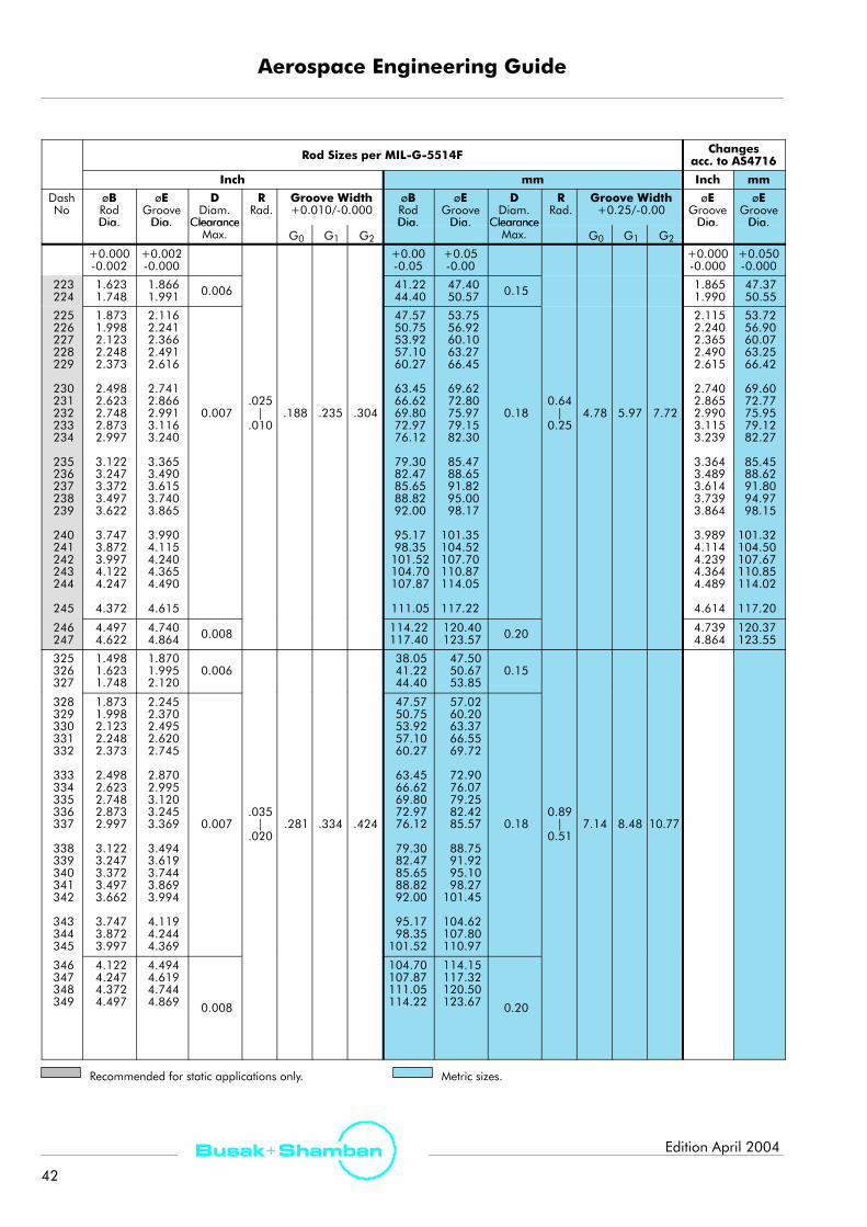
Aerospace Engineering Guide
42
Busak+ Shamban Edition April 2004
Rod Sizes per MIL-G-5514F Changesacc. to AS4716
Inch mm Inch mm
DashNo
øBRodDia.
øEGrooveDia.
DDiam.
Clearance
RRad.
Groove Width+0.010/-0.000
øBRodDia.
øEGrooveDia.
DDiam.
Clearance
RRad.
Groove Width+0.25/-0.00
øEGrooveDia.
øEGrooveDia.Dia. Dia. Clearance
Max. G0 G1 G2
Dia. Dia. ClearanceMax. G0 G1 G2
Dia. Dia.
+0.000-0.002
+0.002-0.000
+0.00-0.05
+0.05-0.00
+0.000-0.000
+0.050-0.000
223224
1.6231.748
1.8661.991 0.006 41.22
44.4047.4050.57 0.15 1.865
1.99047.3750.55
225226227228229
230231232233234
235236237238239
240241242243244
245
1.8731.9982.1232.2482.373
2.4982.6232.7482.8732.997
3.1223.2473.3723.4973.622
3.7473.8723.9974.1224.247
4.372
2.1162.2412.3662.4912.616
2.7412.8662.9913.1163.240
3.3653.4903.6153.7403.865
3.9904.1154.2404.3654.490
4.615
0.007.025|
.010.188 .235 .304
47.5750.7553.9257.1060.27
63.4566.6269.8072.9776.12
79.3082.4785.6588.8292.00
95.1798.35101.52104.70107.87
111.05
53.7556.9260.1063.2766.45
69.6272.8075.9779.1582.30
85.4788.6591.8295.0098.17
101.35104.52107.70110.87114.05
117.22
0.180.64|
0.254.78 5.97 7.72
2.1152.2402.3652.4902.615
2.7402.8652.9903.1153.239
3.3643.4893.6143.7393.864
3.9894.1144.2394.3644.489
4.614
53.7256.9060.0763.2566.42
69.6072.7775.9579.1282.27
85.4588.6291.8094.9798.15
101.32104.50107.67110.85114.02
117.20
246247
4.4974.622
4.7404.864 0.008 114.22
117.40120.40123.57 0.20 4.739
4.864120.37123.55
325326327
1.4981.6231.748
1.8701.9952.120
0.00638.0541.2244.40
47.5050.6753.85
0.15
328329330331332
333334335336337
338339340341342
343344345
1.8731.9982.1232.2482.373
2.4982.6232.7482.8732.997
3.1223.2473.3723.4973.662
3.7473.8723.997
2.2452.3702.4952.6202.745
2.8702.9953.1203.2453.369
3.4943.6193.7443.8693.994
4.1194.2444.369
0.007.035|
.020.281 .334 .424
47.5750.7553.9257.1060.27
63.4566.6269.8072.9776.12
79.3082.4785.6588.8292.00
95.1798.35101.52
57.0260.2063.3766.5569.72
72.9076.0779.2582.4285.57
88.7591.9295.1098.27101.45
104.62107.80110.97
0.180.89|
0.517.14 8.48 10.77
346347348349
4.1224.2474.3724.497
4.4944.6194.7444.869 0.008
104.70107.87111.05114.22
114.15117.32120.50123.67 0.20
Recommended for static applications only. Metric sizes.

Aerospace Engineering Guide
43
Busak+ ShambanEdition April 2004
Rod Sizes per MIL-G-5514F Changesacc. to AS4716
Inch mm Inch mm
DashNo
øBRodDia.
øEGrooveDia.
DDiam.
Clearance
RRad.
Groove Width+0.010/-0.000
øBRodDia.
øEGrooveDia.
DDiam.
Clearance
RRad.
Groove Width+0.25/-0.00
øEGrooveDia.
øEGrooveDia.Dia. Dia. Clearance
Max. G0 G1 G2
Dia. Dia. ClearanceMax. G0 G1 G2
Dia. Dia.
+0.000-0.003
+0.003-0.000
+0.000-0.076
+0.076-0.000
425426427428429
430431432433434
435436437438
4.4974.6224.7474.8724.997
5.1225.2475.3725.4975.622
5.7475.8725.9976.247
4.9745.0995.2245.3495.474
5.5995.7245.8495.9746.099
6.2246.3496.4746.724
0.009
114.22117.40120.57123.75126.92
130.10133.27136.45139.62142.80
145.97149.15152.32158.67
126.34129.51132.69135.86139.04
142.21145.39148.56151.74154.91
158.09161.26164.44170.79
0.23
439440441442443
444445446
6.4976.7476.9977.2477.497
7.7477.9978.497
6.9747.2247.4747.7247.974
8.2248.4748.974
.035|
.020
.375 .475 .579
165.02171.37177.72184.07190.42
196.77203.12215.82
177.14183.49189.84196.19202.54
208.89215.24227.94
0.89|
0.519.53 12.07 14.71
+0.000-0.004
+0.004-0.000
+0.000-0.100
+0.100-0.000
447448449450451
452453454455456
457458459460
8.9979.4979.99710.49710.997
11.49711.99712.49712.99713.497
13.99714.49714.99715.497
9.4749.97410.47410.97411.474
11.97412.47412.97413.47413.974
14.47414.97415.47415.974
0.010
228.52241.22253.92266.62279.32
292.02304.72317.42330.12342.82
355.52368.22380.92393.62
240.64253.34266.04278.74291.44
304.14316.84329.54342.24354.94
367.64380.34393.04405.74
0.25
Recommended for static applications only. Metric sizes.The above dimensions are for reference only, Shamban cannot be held responsible for printing errors etc.600 Series (3/8”) cross section AS4832 recommended for diameters above -442.Table XV Overview of MIL-G-5514F Groove sizes
Series 000 100 200 300 400
Gland Depth 0.056 1.42 0.089 2.26 0.122 3.09 0.186 4.72 0.239 6.06
Gland WidthZero BUR *) 0.094 2.39 0.141 3.58 0.188 4.78 0.281 7.14 0.375 9.53
Gland WidthOne BUR *) 0.149 3.78 0.183 4.65 0.235 5.97 0.334 8.48 0.475 12.07
Gland WidthTwo BUR *) 0.207 5.26 0.245 6.22 0.304 7.72 0.424 10.77 0.579 14.71
Metric sizes. *) BUR = Back-up ring AS4716 has variation in groove depth and width. See spec. for detail

TurconRRRR VL SealRRRR
44
Busak+ Shamban Edition April 2004
TurconR VL SealR*
Description
The TurconR VL SealR incorporates theoretical andempirical experience, in a new generation seal for the 21st
century.
The VL SealR has been developed over the past few yearsas a new generation unidirectional Rod seal. The designhas taken the latest empirical and theoretical experienceinto account in order to optimise performance, friction,leakage and service life. This has been achieved throughin-house testing and qualified in customer applications.See test section.
The back-pumping effect allows the seal to relievepressure trapped between tandem seals or between sealsand double-acting scrapers.
p
VL SealR Ring
O-Ring
Figure 40 TurconR VL SealR
Method of Operation
The sealingmechanism of the TurconR VL SealR (Figure40) is based on the hydrodynamic properties of the seal.The specially formed seal edge has a steep contactpressure gradient on the high pressure side and a shallowcontact pressure gradient on the low pressure side. Thisensures that the fluid film adhering to the piston rod isreturned to the high pressure chamber on the return strokeof the rod. This prevents the micro-fluid layer, that iscarried out of the high pressure chamber when the pistonrod is extended, from causing leaks.
This return delivery property prevents the build-up ofinterstage pressure normally associated with tandem sealconfigurations (Figure 41). Interstage pressure dependson the system pressure speed, the stroke length and thegroove design.
* Patent pending.(US Patent No. 6,497,415)
ppiSEF
: System pressure: Inter seal pressure: Out stroke: In stroke: Lubrication film
p
F
pi
p
E
S
Figure 41 Pressure Distribution in Tandem Installation
Advantages
Compared with current rod seals, the followingparameters have been improved:
- Seal gland: in accordance with MIL-G-5514 / AS4716.0 b/u width (not available in 000 series).
- Tighter leakage control.
- Lower friction: (reduced contact area between seal andmating surface).
- Simplicity of design, using standard size O-Ring.
- Featuring the TurconR StepsealR back pumping effect.
- The seal geometry prevents seal roll at low or shufflingpressure.
- Recommended surface finish max. Ra 0.2 µm / 8 µinch.

TurconRRRR VL SealRRRR
45
Busak+ ShambanEdition April 2004
Technical Data
Operating pressure: 35 MPa (5000 psi)
Speed: up to 15.0 m/s (49.2 ft/s)with reciprocating movements
Temperature range:-54°C to +200°C(-65°F to +390°F)(depending on elastomer material)
Clearance: As per MIL-G-5514F/AS4716
Media: Mineral oil-based hydraulic fluids,flame retardant hydraulic fluids,environmentally safe hydraulic fluids(bio-oils), Phosphate Ester, water andothers, depending on the elastomermaterial (see Table IV, page 16)
Avoid combining extreme limits.
Materials
See Table I, page 12 and Table III, page 15.
Series
The VL SealR follows the series as described inMIL-G-5514F.We recommend that the guidelines for staticand dynamic sizes be followed to ensure a good servicelife for the seal.
For further information on the VL SealR in a non-standarddiameter size, please contact your Shamban salesengineer.
Scale 3:1100 Series
200 Series
300 Series
400 Series
Figure 42 Relationship Between the Profile Cross-Section

TurconRRRR VL SealRRRR
46
Busak+ Shamban Edition April 2004
Ordering Example
VL SealR rod, with Notch.Series No. REL 2 from Table XVI
Dash No: 220
Material: TurconR: T05, see Table I, page 12
Order No. REL N M220 A T05
Series No.
0=No Notch (standard)**N=Notch
Seal part includesCertificate of conformance. (C.C.)
TurconR material code
Cross section*
2
MIL-G-5514F/AS4716 size
* 1=100 Series 4=400 Series2=200 Series3=300 Series
** Notching is recommended for service with highfrequency pulsating pressure, where pressure can bebuilt in the downstream upper corner. The notch willact as a draining channel.
Ordering Example
VL SealR rod, metric sizes.Series No. REL 2 from Table XVI
Rod dia.: 30.0 mm
Material: TurconR: T05, see Table I, page 12
Order No. REL 0 0300 A T05
Series No.
0=No Notch (standard)**N=Notch
Seal part includesCertificate of conformance. (C.C.)
TurconR material code
Cross section*
2
Rod diameter in mm x 10
Note: O-Ring must be ordered seperately. Contact yourShamban sales engineer for dash-sizes.
Table XVI Installation Dimensions
Series Standard Extended Radial Clearance O RingSeries StandardR
ExtendedR
Radial Clearance O-RingC S i
Se es S a da dRange
e dedRange 1500 psi 3000 psi 5000 psi
O gCross-Section
REL 1 -110 to -149 6 to 100mm0.236”-3.937”
0.40mm0.016”
0.25mm0.010”
0.15mm0.006”
1.78mm0.070”
REL 2 -210 to -247 10 to 200mm0.394”-7.874”
0.40mm0.016”
0.25mm0.010”
0.20mm0.008”
2.62mm0.103”
REL 3 -325 to -349 20 to 400mm.787”-15.748”
0.50mm0.020”
0.30mm0.012”
0.20mm0.008”
3.53mm0.139”
REL 4 -425 to -460 35 to 999mm1.387”-39.330”
0.60mm0.024”
0.35mm0.014”
0.25mm0.010”
5.33mm0.210”
Only available in “0” Back-up groove width but can be used in 1 and 2 Back-up grooves using Spacer Rings. Not available in 000 Series.
The seal is designed for MIL-G5514F/AS4716 groovegeometries, but higher clearances can be accommodatedaccording to service conditions.
The seal is designed for 0 b/u groove width, but installationmay be faciliated by the use of a 1 b/u groove width andfilling the groove with a back-up ring, as a spacer.
Seals for 1 & 2 back-up ring groove widths can be usedwith solid b/u-rings (a scarfcut is only recommended forsmall diameters < 25 mm / 1 inch) to ease installation.Special back-up rings can be designed and supplied forunique application requirements.
The standard range can be installed in closed groove b/udown to 20 mm (-211) 0 b/u. Smaller diameters down to16mm (-114) can be installed for 1 or 2 b/u groove width.Back-up ring to be installed afterwards.

TurconRRRR VL SealRRRR
47
Busak+ ShambanEdition April 2004
Test Data
Internal Test ReportTest fluid: MIL-H-83282Pressure: 0-3000 psi cyclic (0-207 bar)Stroke: 76 mm (3 inches)Rate: 1 HzTemp.: 121_C (250_F)Rod size: -214, IHCP R2 0.1-0.2 µm
(4-8 µinch)
Single Seal: 250 000 cyclesAverage wear: -0.20 %Average leakage: 0
Tandem Seal: 500 000 cyclesAverage wear: Primary: -0.42 %
Secondary: -0.11 %Average leakage: 0.11 g ~ 3 drops. (total)
Material: TurconR T19
Figure 43 Internal Test Report

TurconRRRR VL SealRRRR
48
Busak+ Shamban Edition April 2004
Customer Test Report
Working Condition
Rod size: -114 (15.82 mm)hard-chrome
Pressure: 2320 psi (160 bar)Fluid: Phosphate EsterRate: 5 Hz max.Requirement: Zero leakage with friction
below 10 daN (2.2 lb)Temp.: Ambient
Table XVII Test Results
Seal Type 8,000 10,200 10,800 16,000Seal Type 8,000hours
10,200hours
10,800hours
16,000hours
TurconRT Seal
40 400
800drops40
drops400drops
Teststopped
-
TurconRVL SealR
3 4 5 403drops
4drops
5drops
40drops
TurconR VL SealR with Back-up Ring
Grooved TurconR Plus SealR II
Figure 44 Installation
Problem
Low service life, with original equipment. Hard chrome.
Solution
New design with tungsten carbide rod and sealing systemfrom Shamban.

TurconRRRR VL SealRRRR
49
Busak+ ShambanEdition April 2004
VL SealR with Back-up Ring
Grooved Plus SealR IITurconR ExcluderR DC
VL SealR
Back-up Ring with O-Ring
Figure 45 Primary Flight Control
Requirement
Tandem rod seal, with pressure relieving feature.
High frequency up to 10 Hz.
Long service life with exeptional leak-free performance(30 000 flight hours).
Solution
Shamban tandemVL SealRwith excellent performance ontungsten carbide rod.

TurconR Plus SealRII
50
Busak+ Shamban Edition April 2004
TurconR Plus SealRII
Description
The TurconR Plus SealRII, with a long, successful history, isan evolutionary improvement of the Double DeltaR. It is fullyinterchangeable with the Double DeltaRII in mostapplications.
Plus SealRII Cap
Elastomer
p
Figure 46 TurconR Plus SealRII
Method of Operation
The sealing effect of the Plus SealRII comes from the slightinterference of the seal cap with the rod or bore combinedwith the preload from the compressed elastomer. As thepressure increases, the system pressure joins forces with theelastomer and increases the loading of the seal capsignificantly.
The substitution of the proprietary lemon shapedelastomer under the Plus SealRII cap instead of atraditional O-Ring allows the cap to be thicker forincreased wear life. The new elastomer element alsoactivates the seal cap over awider area providing a lowerunit loading.
p p
Double DeltaRII Plus SealRII
Figure 47 Pressure Distribution
The Plus SealRII elastomer is carefully profiled to fit insidethe cap and supports the corners to prevent them fromsinking away from the sealing surface. This reduces the oilfilm under the seal to an absolute minimum.
Free cross-section Installed cross-section
Figure 48 TurconR Plus SealRII Cross-Section
By choosing the grooved version, a further decrease in thefilm thickness can be achieved. The grooves increase thenumber of pressure peaks that the oil filmmust pass under.Another advantage of the grooved seal is that the groovesserve as an oil reservoir when the seal is static. When theseal starts to move, the oil film is quickly re-establishedunder the sliding surface to lubricate the seal. This isespecially important in applications where the stroke isshorter than the seal width and it provides a generalimprovement in wear life. Ask for Shamban test reportR1069.
grooves
GroovedPlus SealRII Cap
Elastomer
p
Figure 49 TurconR Grooved Plus SealRII
The zero back-up width of the seal is generally preferredeven if a wider groove is available in smaller diameters.The extra space in a wider groove is used more efficientlywhen filled with back-up rings. This increases the seal lifewithout notably changing the friction.

TurconR Plus SealRII
51
Busak+ ShambanEdition April 2004
0 b/u 1 b/u 2 b/u
Preferred solution
Figure 50 Use of Back-up Rings (BUR) with Plus SealRII
Where the Plus SealRII is subjected to pressure from bothsides alternately, it should always be equipped withsidewall notches, which allow the pressure to properlyactivate the elastomer (Fig. 51). The Plus SealRII for pistonuse is equipped with notches as standard whereas the rodversion must be specified with notches if they are deemednecessary.
A seal without notches can allow ”blow-by”
A seal with notches prevents ”blow-by”
p
p
p
p
Figure 51 Plus SealRII with Notches
Using a seal without notches may allow ”blow-by”, whichis a situation where the pressure shoots over the top of thePlus SealRII cap and forces the seal down into the groove.See also SAE document AIR 1243.
Advantages
- Good static and dynamic sealing effect- High abrasion resistance- Long life- Low friction, high efficiency- Stick-slip free starting- No vulcanization even during long static periods- Easy installation - foolproof- Available for all MIL-G-5514F/AS4716 sizes.
Technical Data
Operating pressure: 35 MPa (5000 psi) (up to 70 MPa(10 000 psi) with StakbaksR).
Speed: up to 15.0 m/s (49.2 ft/s)with reciprocating movements
Temperature range: -54°C to +200°C(-65°F to +390°F)(depending on elastomer material)
Clearance: As per MIL-G-5514F/AS4716,larger with StakbaksR
Media: Mineral oil-based hydraulic fluids,flame retardant hydraulic fluids,environmentally safe hydraulic fluids(bio-oils), Phosphate Ester, water andothers, depending on the elastomermaterial (see Table IV, page 16)
Avoid combining extreme limits.
Materials
See Table I, page 12 and Table III, page 15.
Series
The Plus SealRII follows the series as described inMIL-G-5514F/AS4716. We recommend that theguidelines for static and dynamic sizes be followed toensure a good service life for the seal.
For further information on the Plus SealRII in anon-standard diameter size, please contact your Shambansales engineer.
Scale 3:1 000 Series
100 Series
200 Series
300 Series
400 Series
Figure 52 Relationship Between the Profile Cross-Section

TurconR Plus SealRII
52
Busak+ Shamban Edition April 2004
Back-up Rings (BUR) for Plus SealRll
The following Back-up Rings are especially designed for usewith the Plus SealRll. The same BUR is used for both rod andbore.
For installation in closed grooves with rod/piston diametersmaller than 18 mm (3/4 inch), we recommend cutBack-up Rings.
1 b/u groove
2 b/u groove
Part No.:BUS1
(S33861)BGS1
(S33861)
BUS7(S33157)BGS7
(S33157)
Uncut
Cut
Uncut
Cut
Figure 53 Plus SealRII with Back-up Rings
For pressures above 35 MPa (5000 psi), we recommendusing one or two StakbakR Back-up Rings with the PlusSealRII.
1 b/u groove
2 b/u groove
Part No.:PP61
(S37061)RP51
(S37051)
PP62(S37062)RP52
(S37052)
Piston
Rod
Piston
Rod
Figure 54 Plus SealRII Set with StakbaksR
The StakbakR Back-up Ring for piston seals has a rigidHiModR anti-extrusion outer ring bonded to a TurconR
inner ring. A wide range of tests at 55 MPa (8000 psi)shows that the StakbakR efficiently protects the seal capfrom extrusion and improves the lifetime of the seal atlower pressures.
The use of StakbakR Back-up Rings is recommended whenthe Plus SealRII is used with increased diametral clearance,high pressure or temperature exceeding 135_C (275_F).
Ordering Example
Grooved Plus SealRII piston, 1 b/u width, Notch.1)
Series No. PP21 from Table XVIII, page 53.
Dash No: 220
Material: TurconR: T05, see Table I, page 12TurelR: NE, see Table III, Page 15
Order No. PP21 M220 A T05 NE
Series No.
MIL-G-5514F/AS4716 sizeSeal part includesCertificate of conformance. (C.C.)
TurconR material code
Elastomer material code
0 = Notch (standard)W = No notch
0
1) Please see note page 53
Ordering Example
Back-up Ring for a one back-up width groove, for usewith Plus SealR IISeries No. BUS1
Dash No: 220
Material: T19
Order No. BUS1 M220 A T19
Series No.
MIL-G-5514F/AS4716 sizeSeal part includesCertificate of conformance (C.C.)
TurconR material code
0 = standard
0
Please Note that Back-up Rings must be orderedseparately!
This example is for ordering the Back-up Ring as shownin Fig. 53.

TurconR Plus SealRII
53
Busak+ ShambanEdition April 2004
Table XVIII TurconR Plus SealRII Types
Seal Groove Type: MIL-G-5514F / AS4716 Comments
Type Width Dia. SizeRange
0 b/u 1 b/u 2 b/u
RangeStandard
dash numbers
PistonPlus SealRII 1)
Foolproof design. 0 b/u width Plus SealRIIwith Back-up Ring recommended for lowfPP50
(S34750)PP81
(S34581)PP82
(S34582) 004 to 460
with Back up Ring recommended for lowfriction.Installable even in small closed grooves, butcare must be taken.
Pistongrooved Plus SealRII 1) PP52
(S30852) 4)
Grooves in surface cap increase wear life andleakage control. Friction is reduced due to thed d f ll b tt(S30852) 4)
PP60(S34760)
PP21(S34721)
PP22(S34722) 004 to 460
gdecreased surface area as well as betterlubrication of the surface.Ask for Shamban test report R1069.
RodPlus SealRII 1)
Foolproof design. 0 b/u width Plus SealRIIwith Back-up Ring recommended for lowf i tiRP75
(S30775)RP71
(S34571)RP72
(S34572) 004 to 460
p gfriction.Installable even in small closed grooves, butcare must be taken.
Rodgrooved Plus SealRII 1)
Grooves in surface cap increase wear life andleakage control. Friction is reduced due to thed d f ll b ttRP55
(S30855)RP11
(S34711)RP12
(S34712) 004 to 460
gdecreased surface area as well as betterlubrication of the surface.Ask for Shamban test report R1069.
PistonPlus SealRII StakbakR Set
)
For pressure above 35 MPa (5000 psi)For long service life. For high temperatureprotection of seal up to +260°C (500°F) 1 b/u
Not available PP61 2)
(S37061)PP62
(S37062) 020 to 460protection of seal up to +260°C (500°F).1 b/uconfiguration incorporates only 1 BUR. Availablealso for size -020 to -028 and -118 to -149even though this is static range!For more on StakbaksR, see BUR section.
RodPlus SealRII StakbakR Set
)
For pressure above 35 MPa (5000 psi)For long service life. For high temperatureprotection of seal up to +260°C (500°F) 1 b/u
Not available RP51 2)
(S37051)RP52
(S37052) 020 to 460protection of seal up to +260°C (500°F).1 b/uconfiguration incorporates only 1 BUR. Availablealso for size -019 to -028 and -117 to -149even though this is static range!For more on StakbaksR, see BUR section.
RodPlus SealRPR Set
Pressure relieving Plus SealRII, used as primaryseal in tandem rod seal concept. Care must bek f ll
Not available RP81 3)
(S38671)RP82
(S38672) 110 to 460
seal in tandem rod seal concept. Care must betaken for correct installation.1 b/u width incorporate only upstream.Also available for piston applications.
1) Notching Options: Piston seals are always delivered as standard with notch. To omit, change 5th character to ”W”. Ex. PP50W.Rod seals are always delivered as standard without notch. To include notch, change 5th character to ”N”. Ex. RP75N.Notches are not possible in 000 series, 0 b/u.
2) Supplied with back-up ring for the downstream side only.
3) Supplied with spacer ring for the upstream side only.
4) Used in North America.

TurconR Double DeltaRII
54
Busak+ Shamban Edition April 2004
TurconR Double DeltaRII
Description
The TurconR Double DeltaRII is the original seal designthat was developed to improve the performance of theO-Ring and Back-up Rings that were used in theMIL-G-5514F/AS4716 and older versions of that standard.
The TurconR Double DeltaRII represents a balancebetween the cap thickness and the squeeze of the O-Ringwithin the MIL-standard groove.
Double DeltaR
Capp
Figure 55 TurconR Double DeltaRII
Method of Operation
The O-Ring preloads the seal cap in the thin, flexiblemiddle section and provides good leakage control evenat low pressures.
In addition to the O-Ring preload, when the systempressure is added the oil film under the seal is furtherreduced. Double DeltaRII will always allow an oil film tobe dragged across the sealing surface. This oil film isnecessary to ensure a long service life for the DoubleDeltaR.
For use of notches and grooves, please see the sectionPlus SealRII, pages 50 - 53.
Groove
GroovedDouble DeltaR Cap
Notch
Figure 56 Grooved Double DeltaRII with Notch
Advantages
- Good static sealing effect- Low friction, high efficiency- Stick-slip-free starting- No adhesion to hardware even during long static periods- Available for all MIL-G-5514F/AS4716 sizes.- Can be made for all O-Ring sizes.
Technical Data
Operating pressure: 35 MPa (5000 psi)
Speed: 15.0 m/s (49,2 ft/s)
Temperature range:-54°C to +200°C(-65°F to +390°F)(depending on elastomer material)
Clearance: As per MIL-G-5514F/AS4716
Media: Mineral oil-based hydraulic fluids,flame retardant hydraulic fluids,environmentally safe hydraulic fluids(bio-oils), Phosphate Ester, water andothers, depending on the elastomermaterial (see Table IV, page 16)
Materials
See Table I, page 12 and Table III, page 15.
Ordering Example
Grooved Double DeltaRII for rod, 1 b/u width,Series No. RD51 from Table XIX, page 55
Dash No: 212
Material: T99
Order No. RD51 M212 A T99
Series No.
MIL-G-5514F/AS4716 sizeSeal part includesCertificate of conformance (C.C.)
TurconR material code
0 = No notch (standard)N = Notch
0
Note: O-Ring must be ordered separately. Sizes followdash number.

TurconR Double DeltaRII
55
Busak+ ShambanEdition April 2004
Series
000 Series
100 Series
200 Series
300 Series
400 Series
Scale 3:1grooves not available
Figure 57 Relationship between the Profile Cross-Section
The Double DeltaRII follows the series as laid out inMIL-G-5514F/AS4716. We recommend that theguidelines for static and dynamic sizes be followed toensure a good service life for the seal.
The Double DeltaRII is also available for the (British Std.)B.S.4518 O-Ring grooves.
For further information on the Double DeltaR II in non-standard size, please contact your Shamban salesengineer.
Table XIX TurconR Double DeltaRII Types
Seal Groove Type: MIL-G-5514F/ AS4716 Comments
Type Width Dia. SizeRange
Co e s
0 b/u 1 b/u 2 b/u (2)Range
Standarddash numbers
PistonDouble DeltaRII (1)
PD60 PD61 PD62 S d d
Foolproof design.Zero back-up width version preferred.C t ff ti l tiPD60
(S30660)PD61
(S30661)PD62
(S30662)Standarddash sizes
p pCost-effective solution.
RodDouble DeltaRII (1)
Foolproof design.Zero back-up width version preferred.C t ff ti l tiRD50
(S30650)RD51
(S30651)RD52
(S30652)Standarddash sizes
p pCost-effective solution.
Pistongrooved Double DeltaRII (1)
Grooves in the surface of the cap increasewear life and leakage control.F 000 i l il bl i 2 b/PD80
(S32860)PD81
(S32861)PD82
(S32862)Standarddash sizes
gFor 000 serie grooves only available in 2 b/uwidth.
Rodgrooved Double DeltaRII (1)
Grooves in the surface of the cap increasewear life and leakage control.F 000 i l il bl i 2 b/RD80
(S32850)RD81
(S32851)RD82
(S32852)Standarddash sizes
gFor 000 serie grooves only available in 2 b/uwidth.
(1) Option Notches: Piston seals are always delivered as standard with notch. To omit, change 5th character to ”W”. Ex. PD60W.Rod seals are always delivered as standard without notch. To include notch, change 5th character to ”N”. Ex. RD81N.Notches are not available in 100 series, 0 + 1 b/u for grooved version.
(2) Seal width: For 2 b/u groove width, 0 or 1 b/u Double DeltaR II recommended with Back-up Rings.

TurconR WedgpakR
56
Busak+ Shamban Edition April 2004
TurconR WedgpakR
Description
The TurconR WedgpakR consists of a proprietarytriangular elastomer supported by two Delta shapedBack-up Rings that prevent the elastomer from spiralingor rolling under severe working conditions.
DeltaBack-up Ring
elastomer
p
Figure 58 TurconR WedgpakR
Method of OperationThe small elastomer contact area of the WedgpakR
design results in a slipper seal-like performance with lowstatic and dynamic friction. At the same time, theelastomer wipes the surface efficiently providing excellentleakage control. The WedgpakR Back-up Rings providesupport and extrusion protection for the elastomer.
Originally designed as a static seal, theWedgpakRhasnow proved to be an excellent seal for dynamicapplications typically demanded in flight controlactuators. The WedgpakR is also used in gas/oilseparators both at high and low pressures.
For further information on WedgpakR dynamicperformance, please contact your Shamban salesengineer and ask for Test Report R1059.
Advantages
- Excellent static and dynamic sealing effect- Low friction, high efficiency- Available for all MIL-G-5514F/AS4716 sizes- Foolproof installation
Technical Data
Operating pressure: 35 MPa (5000 psi)
Speed: 3.0 m/s (9.8 ft/s)
Temperature range:-54°C to +200°C(-65°F to +390°F)(depending on elastomer material)
Clearance: As per MIL-G-5514F/AS4716
Media: Mineral oil-based hydraulic fluids,flame retardant hydraulic fluids,environmentally safe hydraulic fluids(bio-oils), Phosphate Ester, water andothers, depending on the elastomermaterial (see Table IV, page 16)
MaterialsSee Table I, page 12 and Table III, page 15.
SeriesThe WedgpakR follows the series as described inMIL-G-5514F/AS4716. We recommend that theguidelines for static and dynamic sizes be followed toensure a good service life for the seal.
000 Series
100 Series
200 Series
300 Series
400 Series
Scale 3:1
Figure 59 Relationship between the Profile Cross-Sectionfor one Back-up Groove Width

TurconR WedgpakR
57
Busak+ ShambanEdition April 2004
Table XX WedgpakR Types
Seal Groove Type: MIL-G-5514F/ AS4716 Comments
Type Width Dia. SizeRange
Co e s
0 b/u 1 b/u 2 b/uRange
Standarddash size
PistonWedgpakR PA81 PA82
Foolproof design. Excellent static and dynamic leakage control.Cut Back-up Rings are not recommended or available by standard
t b f th f ll i d h iPA80(S34780)
PA81(S34781)
preferred
PA82(S34782)
preferred
004 to 460
p g ypart number for the following dash sizes:0 b/u: Greater than -019, -131, -230 and -3411 b/u: Greater than -028, -142, -235, -349 and -4402 b/u: Greater than -028, -149, -244, -349 and -447
RodWedgpakR RA71 RA72
Foolproof design. Excellent static and dynamic leakage control.Cut Back-up Rings are not recommended or available by standardpart number for the following dash sizes:RA70
(S34770)
RA71(S34771)
preferred
RA72(S34772)
preferred
004 to 460part number for the following dash sizes:0 b/u: Greater than -020, -132, -230 and -3421 b/u: Greater than -028, -142, -236, -349 and -4402 b/u: Greater than -028, -149, -244, -349 and -447
PistonWedgpakREP
For pressure > 35 MPa (5000 psi) and increased extrusion gap.Cut Back-up Rings are not recommended or available by standard
t b f th f ll i d h iN.A. PA1
(S38621)PA2
(S38622) 004 to 460
p g ypart number for the following dash sizes:0 b/u: Greater than -019, -131, -230 and -3411 b/u: Greater than -028, -142, -235, -349 and -4402 b/u: Greater than -028, -149, -244, -349 and -447
RodWedgpakREP
For pressure > 35 MPa (5000 psi) and increased extrusion gap.Cut Back-up Rings are not recommended or available by standard
t b f th f ll i d h iN.A. RA1
(S38611)RA2
(S38612) 004 to 460
p g ypart number for the following dash sizes:0 b/u: Greater than -020, -132, -230 and -3421 b/u: Greater than -028, -142, -236, -349 and -4402 b/u: Greater than -028, -149, -244, -349 and -447
Ordering Example
WedgpakR for piston, 1 b/u width,Series No. PA81 from Table XX
Dash No: 212Material: T99 (standard recommendation)
see Table I, Page 12
Order No. PA81 M212 A T99 NE
Series No.
MIL-G-5514F/AS4716 sizeSeal part includesCertificate of conformance (C.C.)
TurconR material code
Elastomer material code
C
0 = Uncut delta RingC = Cut delta Ring
Note! For small installation in closed grooves withrod/piston diameter smaller than 18 mm (3/4 inch), werecommend cut Back-up Rings. This is specified by adding”C” in the 5th character of the part no.Example: PA81CM212AT99NE.(EP extrusion rings are always delivered with cut.)
Ordering Example
For the WedgpakREP we have the following options:
Order No. M212 A T99 NE
0 = Uncut delta RingC = Cut delta Ring
MIL-G-5514F/AS4716 size
Seal part includesCertificate of conformance (C.C.)
TurconR material code
Elastomer material code
051PA
5 = HiModR Z43 outer ring6 = HiModR Z60 outer ring*
1 = 1 b/u width2 = 2 b/u width
RA = RodPA = Piston
*) Note! Other Compounds are available for the outerring. Contact your Shamban sales engineer.

TurconR WedgpakR
58
Busak+ Shamban Edition April 2004
Case Story
TurconR
WedgpakRTurciteR
SlydringR
TurconR ExcluderRDC
TurconR
WedgpakRTurconR
GroovedPlus SealRII
TurconR
GroovedPlus SealRII
TurconR
Dual Piston Ring
Figure 60 Main Rotor Damper, Helicopter
Problem
Low service life with original equipment.
Solution
New design with tungsten carbide rod and sealing systemfrom Shamban.
Conditions on coated rod
Pressure: Max.30 bar (435 psi)Speed: 400 mm/sec.Temperature: -54_C - +135_C
(-65_F - +275_F)Media: MIL-H-5606Frequency: 6 Hz
Other Application Successes
- ADCAPPS fuel pump swashplate- A330/A340, B747, L1011, DC10Engine driven hydraulic pumps
- C17 OBIGGS constant speed motor- V22 swashplate actuator- RJ hydraulic pump- B757/ B767 ram air turbine- C130 gun elevation actuator- B727 brake valve- Space shuttle payload damper- CH-53 nose landing gear strut- A310 control drive shaft- MD-80 nose gear retract actuator

TurconR HatsealRII
59
Busak+ ShambanEdition April 2004
TurconR HatsealRII
Description
The TurconR HatsealRII is one of the original highperformance seals Shamban developed for the aircraftindustry. It combines the advantages of the elastomercontact seal with those of the slipper seal.
The HatsealRII was designed for demanding aerospaceapplications and is operating successfully in both militaryand commercial hydraulic components. The HatsealRIIcombines the low leakage advantages of an elastomercontact seal and the long life characteristics of TurconR
contact seals.
elastomer
Seal Ringp
Figure 61 TurconR HatsealRII
Method of Operation
The HatsealRII can be divided into 3 zones each with aspecific function, (Figure 62).
Zone 3Zone 2Zone 1
p
Figure 62 HatsealRII, 3 Zone Specific Function
Zone 1 Elastomer contact area
The elastomer has a small but well-defined contact areawhere the oil film on the rod is reduced almost to zero.Dueto the minimal elastomer contact, the friction of the sealis low. This ensures long life performance of the seal.
Zone 2 Slipper Seal area
In this area the TurconR platform is energized by themainbody of the elastomer to work like a slipper seal. Thissection will often run dry but since the TurconR materialshave very low coefficients of friction, this will not damagethe seal. In the unlikely event of a damaged elastomer lipin Zone 1, the slipper seal part will continue to work andgive a leakage performance like a slipper seal.
Zone 3 Back-up Ring area
The built-in Back-up Ring protects the seal from extrusioneven at high operating pressures or speeds. For increasedextrusion gaps and higher temperatures, a number ofspecial versions have been developed (see Figure 67).
Advantages
- Built-in redundancy- Zero leakage- Stick-slip free operation- High frequency applications
Technical Data
Operating pressure: 35 MPa (5000 psi)
Speed: 3.0 m/s (9.8 ft/s)
Temperature range:-54°C to +200°C(-65°F to +390°F)(depending on elastomer material)
Clearance: As per MIL-G-5514F/AS4716,higher with corner reinforcement.
Media: Mineral oil-based hydraulic fluids,flame retardant hydraulic fluids,environmentally safe hydraulic fluids(bio-oils), Phosphate Ester, water andothers, depending on the elastomermaterial (see Table IV, page 16)
Materials
See Table I, page 12 and Table III, page 15.

TurconR HatsealRII
60
Busak+ Shamban Edition April 2004
Table XXI TurconR HatsealRII Types
Seal Groove Type: Rod MIL-G-5514F/ AS4716 Comments
Type Width Dia. SizeR
Co e s
ype
1 b/u 2 b/u
a. S eRange
3 piece HatsealRIITo be used for easier installation with rod diameters below31.75 mm (1 1/4”).F di i b l 20 0 (0 787”) lit l d iRH31
(S34831)RH32
(S34832) -110 to -330
( )For dimensions below 20.0 mm (0.787”) a split gland isrecommended.
2 piece HatsealRIIFor dimensions below 31.75 mm (1 1/4”) a split gland isrecommended.I t ll ti i d i b h ti th T R t
RH51(S34851)
RH52(S34852) -110 to -460
Installation is made easier by heating up the TurconR part.
Ordering ExampleHatsealRll, 2 b/u width, 3 pieces. Series No. RH32 fromTable XXI
Dash No: 212
Material: T99 (standard recommendation)see Table I, page 12
Notes:
The HatsealRII can only be ordered in sizes from -110and up. Only available in rod seal configurations. Forsimilar performance on pistons seal, see the section onWedgpakR.
Order No. RH32 M212 A T99 NG
Series No.
MIL-G-5514F/AS4716 size
Seal part includesCertificate of conformance (C.C.)
TurconR material code
Elastomer material code
0
Standard
Series
The HatsealRII is designed to fit the MIL-G-5514F/AS4716gland specification. We recommend that the guidelines forstatic and dynamic sizes be followed to ensure a good servicelife.
For further information on the HatsealRII in non-standardsizes, please contact your Shamban sales engineer.
100 Series
200 Series
300 Series
400 Series
Scale 3:1
Figure 63 Relationship Between the Profile Cross-Section
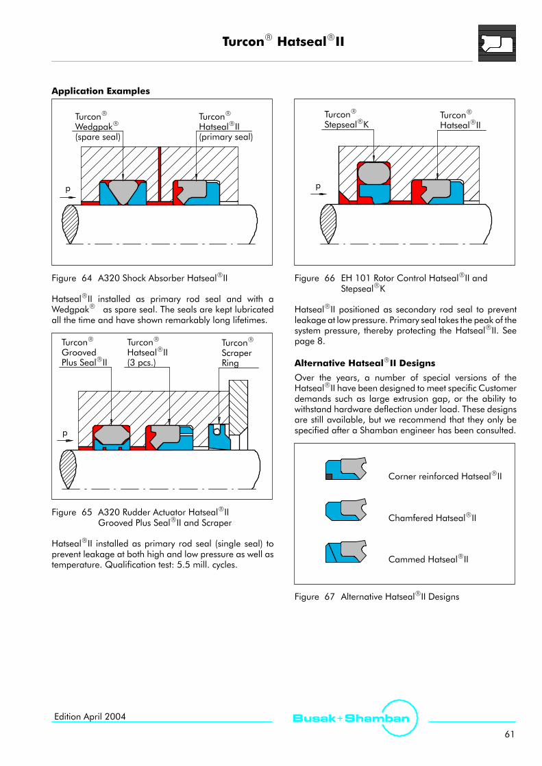
TurconR HatsealRII
61
Busak+ ShambanEdition April 2004
Application Examples
p
TurconR
HatsealRII(primary seal)
TurconR
WedgpakR(spare seal)
Figure 64 A320 Shock Absorber HatsealRII
HatsealRII installed as primary rod seal and with aWedgpakR as spare seal. The seals are kept lubricatedall the time and have shown remarkably long lifetimes.
p
TurconR
ScraperRing
TurconR
GroovedPlus SealRII
TurconR
HatsealRII(3 pcs.)
Figure 65 A320 Rudder Actuator HatsealRIIGrooved Plus SealRII and Scraper
HatsealRII installed as primary rod seal (single seal) toprevent leakage at both high and low pressure as well astemperature. Qualification test: 5.5 mill. cycles.
p
TurconR
StepsealRKTurconR
HatsealRII
Figure 66 EH 101 Rotor Control HatsealRII andStepsealRK
HatsealRII positioned as secondary rod seal to preventleakage at low pressure. Primary seal takes the peak of thesystem pressure, thereby protecting the HatsealRII. Seepage 8.
Alternative HatsealRII Designs
Over the years, a number of special versions of theHatsealRII have been designed to meet specific Customerdemands such as large extrusion gap, or the ability towithstand hardware deflection under load. These designsare still available, but we recommend that they only bespecified after a Shamban engineer has been consulted.
Corner reinforced HatsealRII
Chamfered HatsealRII
Cammed HatsealRII
Figure 67 Alternative HatsealRII Designs

TurconR T-Seal
62
Busak+ Shamban Edition April 2004
TurconR T-Seal
Description
The TurconR T-Seal consists of a T-shaped elastomericsealing element supported by a TurconR Back-up Ring onboth sides.
The T-Seal is available for zero, one and two Back-up Ringwidths and all sizes of rod and piston glands as perMIL-G-5514F/AS4716.
Back-up Ring
elastomer
p
Figure 68 TurconR T-Seal
Method of Operation
The T-Seal utilizes an optimally designed elastomercomponent to maximize leakage control while offeringexcellent extrusion protection in a symmetric design.
The large elastomer footprint makes the T-Seal a goodstatic seal. The one and two Back-up Ring widths offerespecially good protection against extrusion.
Although the T-Seal is satisfactory in light duty dynamicapplications, the WedgpakR design is preferred for moredemanding dynamic applications. Ask for test report R1059.
Zero back-up width
One back-up width
Two back-up width
Figure 69 Comparison Between T-Seal and O-Ringwith Back-up Rings
Advantages- Good static sealing effect- Cost-effective- Available for all sizes of MIL-G-5514F/AS4716- Approved for a large number ofNational Stock Numbers
- Provides bi-directional sealing
Technical DataOperating pressure: 35 MPa (5000 psi) static
21 MPa (3000 psi) dynamic
Speed: 1 m/s (3.3ft/s)
Temperature range:-54°C to +200°C(-65°F to +390°F)(depending on elastomer material)
Clearance: As per MIL-G-5514F/AS4716
Media: Mineral oil-based hydraulic fluids,flame retardant hydraulic fluids,environmentally safe hydraulic fluids(bio-oils), Phosphate Ester, water andothers, depending on the elastomermaterial (see Table IV, page 16)
Materials
See Table I, page 12 and Table III, page 15.

TurconR T-Seal
63
Busak+ ShambanEdition April 2004
Series
The T-Seal follows the series as described inMIL-G-5514F/AS4716. We recommend that theguidelines for static and dynamic sizes be followed toensure a good service life for the seal.
For more information on the T-Seal in non-standard sizes,please contact your Shamban sales engineer.
1 b/u 2 b/u0 b/u
Scale 3:1000 series
100 Series
200 Series
300 Series
400 Series
Figure 70 Relationship Between the Profile Cross-Sections
Table XXII T-Seal Types
Seal Groove Type: MIL-G-5514F/ AS4716 Comments
Type Width Dia. SizeRange
Co e s
0 b/u 1 b/u 2 b/uRange
Standarddash size
PistonT-Seal
Good static sealing effect.WedgpakR preferred for all dynamic
li tiPB20(S38420)
PB21(S38421)
PB22(S38422) 006 to 460
gp p yapplications.
RodT-Seal
Good static sealing effect.WedgpakR preferred for all dynamic
li tiRB10
(S38410)RB11
(338411)RB12
(S38412) 005 to 460
gp p yapplications.

TurconR T-Seal
64
Busak+ Shamban Edition April 2004
Ordering Example
T-Seal 2 b/u width,Series No. RB12 from Table XXII, page 63
Dash No: 210
Material: T99, see Table I, page 12
Order No. RB12 M212 A T99 NG
Series No.
MIL-G-5514F/AS4716 sizeSeal part includesCertificate of conformance (C.C.)
TurconR material code
Elastomer material code
0 = Uncut Back-up RingC = Cut Back-up Ring
C
Note! For small installation in closed grooves withrod/piston diameter smaller than 18 mm (3/4 inch), werecommend cut Back-up Rings. This is specified by adding”C” in the 5th character of the part no.Example: PB21CM212AT99NG.
T-Seal References
- F/A-18 - NLG shock strut- F/A-18 - Nose wheel steering actuator- F/A-18 - Horizontal stabilizer actuator- F-16 - MLG strut- F-16 - Integrated servoactuator- F-16 - Rudder actuator- F-15 - Ratio changer actuator- F-15 - Yaw ratio controller- UH60 - Tail rotor actuator- B737/B757 - Main and nose landing gear

TurconR AQ-SealR5
65
Busak+ ShambanEdition April 2004
TurconR AQ-SealR5* (For use in MIL-Standard Grooves)
Description
The TurconR AQ-SealR5 is a patented development of theproven standard AQ-SealR.
The AQ-SealR5 is a double-acting piston seal designedfor reciprocating or helical movements.
The AQ-SealR5 is comprised of a dynamic sealingelement in TurconR with a limited footprint elastomericQUAD-RINGR1) Seal inset centrally into its sealing face. Theseal ring is energized by two elastomeric O-Rings.
p QUAD-RINGR Seal
TurconR Seal ring
Figure 71 TurconR AQ-SealR5
Method of Operation
The AQ-SealR5 combines the benefits of a low-frictionTurconR slipper seal with the high sealing characteristicsof an elastomeric seal by incorporating a limited foot printQUAD-RINGR Seal in the dynamic sealing face. Thisoptimizes leakage control while minimizing friction.
The unique characteristics of the AQ-SealR5 are thespecial seal profile with a defined seal edge and the useof two O-Rings as energizing elements to optimize thepressure profile.
Diametral Clearance
The AQ-SealR5 can be installed in MIL-G-5514 F/AS4716(-300 and -400 sizes only) glands using the standarddiametral clearance. If a larger clearance is needed or if thehardware deflects excessively during operation, the diametralclearance will increase. In this case we recommend the useof SlydringR bearing rings with the AQ-SealR5. Please seesection ”TurciteR SlydringR/LuytexR SlydringR”, page 114.
* Patent-No. EP 0 424 372
1) Reg. trade mark of Minnesota rubber
Advantages
- High sealing effect in applications requiring mediaseparation, e.g. fluid/fluid or fluid/gas
- Double security through the combination of low-frictionspecial materials with elastomer seals
- Low gas permeation rate- Higher pressure application limit, higher sliding speedcompared to the T-Seal
- Outstanding sliding properties, no stick-slip effect- Designed for zero back-up ring width groove
Technical Data
Operating pressure: 35 MPa (5000 psi)
Speed: up to 3.0 m/s (9.8 ft/s)with reciprocating movements
Temperature range:-54°C to +200°C(-65°F to +390°F)(depending on elastomer material)
Clearance: As per MIL-G-5514F/AS4716,higher with StakbaksR
Media: For all common hydraulic fluids,including bio-oils and gases(see Table IV, page 16)
Materials
See Table I, page 12 and Table III, page 15.
Series
The AQ-SealR5 follows the 300 and 400 Series describedin the MIL-G-5514F/AS4716.
For more information on the AQ-SealR5 in non-standardsizes, please contact your Shamban sales engineer.
Scale 3:1
300 Series 400 Series
Figure 72 Relationship Between the Profile Cross-Section

TurconR AQ-SealR5
66
Busak+ Shamban Edition April 2004
Application Example
Figure 73 Bootstrap Reservoir with TurconR AQ-SealR5
Case Story
The AQ-SealR5 is used in the Jetstream 31 propeller pitchadjuster mechanism with the following working conditions:Temperature: -50_C to +120_C (-58_F to +248_F)Pressure: 0.35 MPa to 5.5 MPa
(50 to 800 psi)Fluid: MIL-L-23699CService life: 7500 hours
Propeller hubSpring
Adjuster piston
Figure 74 Jetstream 31 Propellers(by courtesy of Dowty Aerospace Propellers)
Ordering Example
AQ-SealR5,Series No. PQ20 (Old Series No. S38620)
Dash No: 330
Material: T99 (standard), see Table I, Page 12
Order No. PQ20 M330 A T99 NG
Series No.
MIL-G-5514F/AS4716 sizeSeal part includesCertificate of conformance (C.C.)
TurconR material code
Elastomer material code for QUAD-RINGR
Standard
0
Note: O-Ring must be ordered seperately. Sizes can befound in Table XXIII, page 67.

TurconR AQ-SealR5
67
Busak+ ShambanEdition April 2004
Installation AQ-SealR5, Series No. PQ20 (Old Series No. S38620)
GøB
Break edge 0.13mm (.005 inch )+0.13-0.00
+.005-.000 0_ (typ. 0_)
+5_-0_
D/2Diametral Clearance(see page 65)
RRadius Groove width
Groove Dia.
Bore Dia.øA
Figure 75 Installation Drawing
Table XXIII Groove Dimensions
D h
øABore Dia.
øBGroove Dia. G R O-
RingDash
QUAD-RINGRDashDash
No Inch mm Inch mm Inch Inch
gDashNo
DashNoNo
+0.002-0.000
+0.05-0.00
+0.000-0.002
+0.00-0.05
Inch/
mm
Inch/
mmAS
568 AAS
568 A
325326327328329
330331332333334
335336337338339
340341342343344
345346347348349
1.8671.9922.1182.2432.368
2.4932.6182.7432.8682.993
3.1183.2433.3683.4933.618
3.7433.8683.9934.1184.243
4.3684.4934.6194.7434.868
47.4250.6053.8056.9760.15
63.3266.5069.6772.8576.02
79.2082.3785.5588.7291.90
95.0798.25101.42104.60107.77
110.95114.12117.32120.47123.65
1.4951.6201.7461.8711.996
2.1212.2462.3712.4962.621
2.7462.8712.9963.1213.246
3.3713.4963.6213.7463.871
3.9964.1214.2464.3714.496
37.9741.1544.3547.5250.70
53.8757.0560.2263.4066.57
69.7572.9276.1079.2782.45
85.6288.8091.9795.1598.32
101.50104.67107.85111.02114.20
.281|
.291
7.14|
7.39
.020|
.035
0.51|
0.89
128130132133135
137139141143145
147149151151152
152153153154154
155155156156157
031032033034035
036037038039040
041041042042043
043044044045045
046046047047048
+0.002-0.000
+0.05-0.00
+0.000-0.002
+0.00-0.05
.375|
425426427428429430
4.9745.0995.2245.3495.4745.599
126.34129.51132.69135.86139.04142.21
4.4974.6224.7474.8724.9975.122
114.22117.40120.57123.75126.92130.10
|.385
9.53|
9.78
245246247248249250
158158159159160160
D h
øABore Dia.
øBGroove Dia. G R O-
RingDash
QUAD-RINGRDashDash
No Inch mm Inch mm Inch/
Inch/
DashNo
DashNoNo
+0.002-0.000
+0.05-0.00
+0.000-0.002
+0.00-0.05
Inch/
mm
Inch/
mm AS568 A
AS568 A
431432433434
435436437438439
440441442443444
445446
5.7245.8495.9746.099
6.2246.3496.4746.7246.974
7.2247.4747.7247.9748.224
8.4748.974
145.39148.56151.74154.91
158.09161.26164.44170.79177.14
183.49189.84196.19202.54208.89
215.24227.94
5.2475.3725.4975.622
5.7475.8725.9976.2476.497
6.7476.9977.2477.4977.747
7.9978.497
133.27136.45139.62142.80
145.97149.15152.32158.67165.02
171.37177.72184.07190.42196.77
203.12215.82
.375|
.385
9.53|
9.78
.020|
.035
0.51|
0.89
251252253254
255256257259259
260261262263264
265267
161161162162
163163164165166
167168169170171
172174
+0.002-0.000
+0.05-0.00
+0.000-0.002
+0.00-0.05
447448449
450451452453454
455456457458459460
9.4749.97410.474
10.97411.47411.97412.47412.974
13.47413.97414.47414.97415.47415.974
240.64253.34266.04
278.74291.44304.14316.84329.54
342.24354.94367.64380.34393.04405.74
8.9979.4979.997
10.49710.99711.49711.99712.497
12.99713.49713.99714.49714.99715.497
228.52241.22253.92
266.62279.32292.02304.72317.42
330.12342.82355.52368.22380.92393.62
269271273
275276277278278
279279280280281281
176178179
180181182183184
185186187188189190
Metric sizes.

TurconR VarisealR
68
Busak+ Shamban Edition April 2004
TurconR VarisealR
Design Concept
VarisealR is a spring-energized seal. The VarisealR
performs reliably in a wide range of applications whereconventional elastomeric seals fail due to chemical attack,extreme heat or cold, extrusion, friction or compressionset. The basic VarisealR design has two elements:
1. A pressure-actuated, ”U-shaped” jacket.
2. A metal spring.
The U-shaped jacket allows the system pressure toenergize the sealing lips, forcing them against the matinghardware with higher load as the system pressure rises.
The VarisealR is machined to very close tolerances,using only premium-grade materials. Each design isavailable in imperial and metric dimensions. Thestandard size range includes diameters from 3 mm(0.12 in) to 2500*) mm (8 ft).
System pressure
Figure 76 TurconR VarisealR Energized bythe System Pressure
Spring Load
The VarisealR is energized by a spring made fromstainless steel, HastelloyR, or ElgiloyR. The springprovides the load required for sealing when the systempressure is too low to fully actuate the lips. The springalso compensates for variations in gland tolerancesandnormal wear of the seal. As a seal loading device, ametal spring is more accurate for the control of frictionthan other devices, such as O-Rings.
See Spring Types, Table XXIV, page 70 for spring selection.
*) with extended size capability available.
Spring force
Figure 77 Spring Force
Jacket Material
VarisealR jackets are made from a variety ofhigh-performance polymers. There are two categories ofmaterial available:
1. TurconR Engineered-polymer compounds,based on low-friction TurconR resins, are foundin the majority of VarisealR applications.
2. ZurconR Compounds have outstandingabrasion-resistance.
See TurconR and ZurconR Seal Materials, pages 12 and13 for material selection.
High Performance
The unique design andmaterial properties of the VarisealR
provide design engineers with an assortment of solutionsfor difficult applications. Some of the outstandingcapabilities of the VarisealR include:
- Very low friction.
- High speed service.
- Universal chemical compatibility.
- Cryogenic service to -273°C (-459.67°F).
- High-temperature service to +260°C (+500°F).Higher peak temperatures are possible.
- Permanent elasticity with immunity to aging,embrittlement and compression set.
- No lubrication required.

TurconR VarisealR
69
Busak+ ShambanEdition April 2004
Spring Types
A metal spring is incorporated in the design to provideelasticity to the seal. The spring makes the sealpermanently elastic despite changes in operatingtemperature, pressure or chemicals. Each of the springtypes found in the VarisealR has unique properties thataffect seal performance. The two most importantproperties of the spring - besides the corrosion resistanceof the metal - are its load value and deflection range. Thespring load has influence on the sealing ability, friction,and wear rate of the seal. The deflection rangedetermines the ability of the VarisealR to take up wearand compensate for variations in gland dimensions dueto hardware tolerances or eccentricity.
V-Spring (Cantilever)
This spring, used in the VarisealRM types and the RotoVarisealR, operates as a set of ”cantilever beams”extending from an arc at the bottom of the spring. Theshape of the spring causes the load to be focused on thefront edge of the sealing lip, contributing to the positive
wiping action of the seal. A Cantilever-beam spring has amoderate load and deflection range.
Helical Spring
Helical spring, used in the VarisealRH types, has a muchhigher unit load and a shorter deflection range than theother spring types. It is therefore excellent for staticapplications or very slow speeds where friction andwear arenot the primary concerns. The high spring load makes theVarisealRH suitable for applications with low temperatures.Under these conditions the 200 Series or larger is prefered.
SlantcoilR Spring
The patented SlantcoilR Spring, used in the VarisealRW,types consists of round wire formed into slanted coils. Thecoils load the seal radially.The SlantcoilR Spring provides a unique spring-loadingcharacteristic. The spring gives a relatively constant loadover a wide deflection range. This allows more accuratecontrol of friction during the working life of the seal.
Helical spring
V-spring
Percent deflection from free height
Springforce
Slantcoil SpringR
25 50
Figure 78 The Graph Represents a General Comparison of Load Curves for the Three Spring Types.The ”O” Indicates the Load Point when Installed in the Gland.
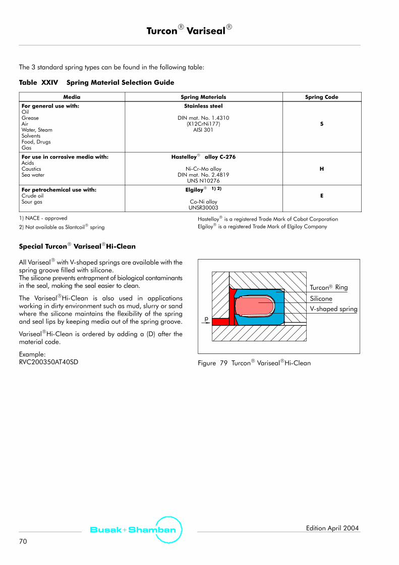
TurconR VarisealR
70
Busak+ Shamban Edition April 2004
The 3 standard spring types can be found in the following table:
Table XXIV Spring Material Selection Guide
Media Spring Materials Spring Code
For general use with:OilGreaseAirWater, SteamSolventsFood, DrugsGas
Stainless steel
DIN mat. No. 1.4310(X12CrNi177)
AISI 301S
For use in corrosive media with:AcidsCausticsSea water
HastelloyR alloy C-276
Ni-Cr-Mo alloyDIN mat. No. 2.4819
UNS N10276
H
For petrochemical use with:Crude oilSour gas
ElgiloyR 1) 2)
Co-Ni alloyUNSR30003
E
1) NACE - approved
2) Not available as SlantcoilR springHastelloyR is a registered Trade Mark of Cabot CorporationElgiloyR is a registered Trade Mark of Elgiloy Company
Special TurconR VarisealRHi-Clean
All VarisealR with V-shaped springs are available with thespring groove filled with silicone.The silicone prevents entrapment of biological contaminantsin the seal, making the seal easier to clean.
The VarisealRHi-Clean is also used in applicationsworking in dirty environment such as mud, slurry or sandwhere the silicone maintains the flexibility of the springand seal lips by keeping media out of the spring groove.
VarisealRHi-Clean is ordered by adding a (D) after thematerial code.
Example:RVC200350AT40SD
RTurcon
V-shaped spring
Silicone
p
Ring
Figure 79 TurconR VarisealRHi-Clean

TurconR VarisealR
71
Busak+ ShambanEdition April 2004
Installation Recommendations for Rod, MIL-G-5514F/AS4716 SizesTypes M14, W14 and H14
L1
r1
D/2
Split groove
Type
Cross section
M14 W14 H14
Series No. RV93 RV95 RV91
For installation in stepped groovesee page 76
øAøB
Figure 80 Installation Drawing
Table XXV Groove Dimensions
Series Rod DiameterøB h9
Groove Diameter2) GrooveWidth
Radius Radial Clearance3)D/2 max.
StandardRange
Extended1)Range øA H9 L1 +.010 r1
<2 MPa(300 psi)
<10 MPa(1500 psi)
<20 MPa(2900 psi)
<40 MPa(5800 psi)
000 .123 - 1.373 .123 - 3.997 øB + .112 .094 .010 .008 .004 .003 .002
100 .373 - 2.811 .185 - 5.497 øB + .178 .141 .015 .010 .006 .004 .003
200 .748 - 4.622 .248 - 8.997 øB + .244 .188 .015 .014 .008 .006 .003
300 1.498 - 4.497 .873 - 10.497 øB + .370 .281 .015 .020 .010 .008 .004
400 4.497 - 15.497 1.498 - 15.497 øB + .478 .375 .020 .024 .012 .010 .005
1) Available on request2) By diameters larger than ”Recommended Range”: The tolerance onøB and øA is changed from h9/H9 to h8/H8
3) For temperatures≥ 80_C (176_F) we recommend reducing theradial clearance. At pressures > 40 MPa (5800 psi):D/2 max. use H8/h8.In both cases we recommend that you contact your local Shambanrepresentative.
Ordering ExampleTurconR VarisealRH, Series RV91.Rod diameter: øB = 1.623 (MIL-G-5514F-326)Part No: RV910M326
Select the materials from Table I, page 12 and Table XXIV,page 70. The corresponding code numbers areappended to the Part No. Together these form the ordernumber.
The order number for all intermediate sizes not shown inTable XXV can be determined following the example opposite.
Note that the series or cross section of the seal is automaticallygiven by the sizes suitable for the selected dash number ofMIL-G-5514F-326.
M326 T40 SRV91
Material Code - TurconR Ring
Series No.
Order No.
Material Code - spring
MIL-G-5514F/AS4716 sizeSeal part includesCertificate of conformance (C.C.)
(D)
Hi-Clean - option
A0
Standard

TurconR VarisealR
72
Busak+ Shamban Edition April 2004
Installation Recommendations for Bore, MIL-G-5514F/AS4716 SizesTypes M14, W14 and H14
Split groove
Type
Cross section
M14 W14 H14
Series No. PV93 PV95 PV91
For installation in stepped groovesee page 76
D/2
L1r1
øA
øB
Figure 81 Installation Drawing
Table XXVI Groove Dimensions
Series Bore DiameterøA H9
Groove Diameter2) GrooveWidth
Radius Radial Clearance3)D/2 max.
StandardRange
Extended1)Range øB h9 L1 +.010 r1
<2 MPa(300 psi)
<10 MPa(1500 psi)
<20 MPa(2900 psi)
<40 MPa(5800 psi)
000 .235 - 1.491 .235 - 4.118 øA - .112 .094 .010 .008 .004 .003 .002
100 .550 - 2.993 .360 - 5.680 øA - .178 .141 .015 .010 .006 .004 .003
200 .991 - 4.868 .485 - 9.243 øA - .244 .188 .015 .014 .008 .006 .003
300 1.867 - 4.868 1.241 - 10.868 øA - .370 .281 .015 .020 .010 .008 .004
400 4.974 - 15.974 1.974 - 15.974 øA - .478 .375 .020 .024 .012 .010 .005
1) Available on request2) By diameters larger than ”Recommended Range”: The tolerance onøA and øB is changed from h9/H9 to h8/H8
3) At pressures > 40 MPa (5800 psi): D/2 max. use H8/h8.We recommend that you contact your local Shamban sales engineer.
Ordering ExampleTurconR VarisealRM, Series PV93.Bore diameter: øA = 1.366 (MIL-G-5514F-216)Part No: PV930M216
Select the materials from Table I, page 12 and Table XXIV,page 70. The corresponding code numbers areappended to the Part No. Together these form the ordernumber.The order number for all intermediate sizes not shown inTable XXVI can be determined following the exampleopposite.
Note that the series or cross section of the seal is automaticallyfollowing the sizes suitable for the selected dash number ofMIL-G-5514/AS4716.
M216 T40 SPV93
Material Code - TurconR Ring
Series No.
Order No.
Material Code - spring
MIL-G-5514F/AS4716 sizeSeal part includesCertificate of conformance (C.C.)
(D)
Hi-Clean - option
A0
Standard

TurconR VarisealR
73
Busak+ ShambanEdition April 2004
Installation Recommendations for Rod, Metric SizesTypes M2, W and H
L1
r1
D/2
Split groove
Type
Cross section
M2 W H
Series No. RVA RVW RVE
For installation in stepped groovesee page 76
øAøB
Figure 82 Installation Drawing
Table XXVII Groove Dimensions
Series Series No. Rod DiameterøB h9
GrooveDiameter
GrooveWidth
Radius Radial Clearance3)D/2 max.
M2 W H StandardRange
Extended1)Range øA H9 L1 +0.2 r1
<2 MPa(300 psi)
<10 MPa(1500 psi)
<21 MPa(3000 psi)
<40 MPa(5800 psi)
000 RVA0 RVW0 RVE0 3.0 - 9.9 3.0 - 40.03) øB + 2.9 2.4 0.4 0.20 0.10 0.08 0.05
100 RVA1 RVW1 RVE1 10.0 - 19.9 6.0 - 200.02) øB + 4.5 3.6 0.4 0.25 0.15 0.10 0.07
200 RVA2 RVW2 RVE2 20.0 - 39.9 10.0 - 400.02) øB + 6.2 4.8 0.6 0.35 0.20 0.15 0.08
300 RVA3 RVW3 RVE3 40.0 - 119.9 20.0 - 700.02) øB + 9.4 7.1 0.8 0.50 0.25 0.20 0.10
400 RVA4 RVW4 RVE4 120.0 - 999.9 35.0 - 999.92) øB + 12.2 9.5 0.8 0.60 0.30 0.25 0.12
500 - - RVE5 1000.0 - 2500.9 80.0 -2500.02) øB + 19.0 15.0 0.8 0.90 0.50 0.40 0.20
1) Available on request2) By diameters larger than ”Recommended Range”: The tolerance onøB and øA is changed from h9/H9 to h8/H8
3) For temperatures≥ 80_C (176_F) we recommend reducing the radialclearance. At pressures > 40 MPa (5800 psi): D/2 max. use H8/h8.In both cases we recommend that you contact your local Shambanrepresentative.
Ordering Example
TurconR VarisealRH, Series RVE3.Rod diameter: øB = 80.0 mm (3.150 in)Part No: RVE300800
Select the materials from Table I, page 12 and Table XXIV,page 70. The corresponding code numbers are appendedto the Part No. Together these form the order number.
The order number for all intermediate sizes not shown inTable XXVII can be determined by following the exampleshown opposite here.
0800 T40 SRVE3
Material Code - TurconR Ring
Series No.
Order No.
Material Code - spring
Rod diameter x 10Seal part includesCertificate of conformance (C.C.)
(D)
Hi-Clean - option
A0
Standard

TurconR VarisealR
74
Busak+ Shamban Edition April 2004
Installation Recommendations for Bore, Metric SizesTypes M2, W and H
Split groove
Type
Cross section
M2 W H
Series No. PVA PVW PVE
D/2
L1r1
For installation in stepped groovesee page 76
øA
øB
Figure 83 Installation Drawing
Table XXVIII Groove Dimensions
Series Series No. Bore DiameterøA H9
GrooveDia.
GrooveWidth
Radius Radial Clearance3)D/2 max.*
M2 W H RecommendedRange
Extended1)Range øB h9 L1 +0.2 r1
<2 MPa(300 psi)
<10 MPa(1500 psi)
<21 MPa(3000 psi)
<40 MPa(5800 psi)
000 PVA0 PVW0 PVE0 6.0 - 13.9 6.0 - 40.0 øA - 2.9 2.4 0.4 0.20 0.10 0.08 0.05
100 PVA1 PVW1 PVE1 14.0 - 24.9 10.0 -200.02) øA - 4.5 3.6 0.4 0.25 0.15 0.10 0.07
200 PVA2 PVW2 PVE2 25.0 - 45.9 16.0 -400.02) øA - 6.2 4.8 0.6 0.35 0.20 0.15 0.08
300 PVA3 PVW3 PVE3 46.0 -124.9 28.0 -700.02) øA - 9.4 7.1 0.8 0.50 0.25 0.20 0.10
400 PVA4 PVW4 PVE4 125.0 -999.9 45.0 -999.92) øA - 12.2 9.5 0.8 0.60 0.30 0.25 0.12
500 - - PVE5 1000.0 -2500.0 100.0 -2500.02) øA - 19.0 15.0 0.8 0.90 0.50 0.40 0.20
1) Available on request2) By diameters larger than ”Recommended Range”:The tolerance onøA and øB is changed from h9/H9 to h8/H8
3) For temperatures≥ 80_C (176_F) we recommend reducing the radialclearance. At pressures > 40 MPa (5800 psi): D/2 max. use H8/h8.In both cases we recommend that you contact your local Shambanrepresentative.
Ordering Example
TurconR VarisealRM2, Series PVA3.Bore diameter: øA = 80.0 mm (3.150 in)Part No: PVA300800
Select the materials from Table I, page 12 and Table XXIV,page 70. The corresponding code numbers areappended to the Part No. Together these form the ordernumber.The order number for all intermediate sizes not shown inTable XXVIII can be determined by following the exampleshown opposite here.
0800 T40 SPVA3
Material Code - TurconR Ring
Series No.
Order No.
Material Code - spring
Bore diameter x 10Seal part includesCertificate of conformance (C.C.)
(D)
Hi-Clean - option
A0
Standard

TurconR VarisealR
75
Busak+ ShambanEdition April 2004
Installation in Closed Grooves
Installation in split or lipped grooves is recommended.Installation in closed grooves is possible for rod and borediameters according to the following tables.
Rod Seals
Break corner R 0.2 max.
øB
Figure 84 Installation in Closed Groove
Table XXIX Installation of VarisealRM Typesinto Closed Grooves
Series No.R d S l
øBmin. øBmin.Se es o.Rod Seals
Inch mm
000 RVA0 1.250 30.0
100 RVA1 2.750 70.0
200 RVA2 4.375 110.0
300 RVA3 11.750 300.0
400 RVA4 19.500 500.0
Table XXX Installation ofVarisealRH and VarisealRW Typesinto Closed Grooves
Series No.R d S l
øBmin. øBmin.Se es o.Rod Seals
Inch mm
000 RVE0 and RVW0 1.000 30.0
100 RVE1 and RVW1 2.500 70.0
200 RVE2 and RVW2 4.250 110.0
300 RVE3 and RVW3 9.000 230.0
400 RVE4 and RVW4 15.250 400.0
500 RVE5 27.560 700.0
Metric sizes.
Piston Seals
Break corner R 0.2 max.
øA
Figure 85 Installation in Closed Groove
Table XXXI Installation of VarisealRM Typesinto Closed Grooves
Series No.Pi S l
øAmin. øAmin.Se es o.Piston Seals
Inch mm
000 PVA0 1.375 35.0
100 PVA1 2.000 50.0
200 PVA2 2.750 70.0
300 PVA3 4.125 105.0
400 PVA4 5.500 140.0
Table XXXII Installation ofVarisealRH and VarisealRW Typesinto Closed Grooves
Series No.Pi S l
øAmin. øAmin.Se es o.Piston Seals
Inch mm
000 PVE0 and PVW0 .750 20.0
100 PVE1 and PVW1 1.125 35.0
200 PVE2 and PVW2 1.750 48.0
300 PVE3 and PVW3 2.375 75.0
400 PVE4 and PVW4 3.750 95.0
500 PVE5 11.800 300.0

TurconR VarisealR
76
Busak+ Shamban Edition April 2004
Installation in Stepped Grooves
Rod Seals
L1
r1
X
D/2
ZøA
øB
Figure 86 Stepped Grooves, Rod
Table XXXIII Groove Dimensions, Inch Sizes
Series Lip X Max.Radius
Min.Chamfer Z
Min.Seal ID
000 .008/.012 .005 .098 .250
100 .010/.015 .005 .138 .375
200 .015/.020 .007 .138 .750
300 .017/.023 .010 .177 1.000
400 .022/.028 .010 .295 2.000
Table XXXIV Groove Dimensions, mm Sizes
Series Rod SealTypes
LipHeight
ChamferLength
Radiusmax.
M2 W H X1) Zmin r1
000 RVA0 RVW0 RVE0 0.4 2.5 0.4
100 RVA1 RVW1 RVE1 0.6 3.5 0.4
200 RVA2 RVW2 RVE2 0.7 3.5 0.6
300 RVA3 RVW3 RVE3 0.8 4.5 0.8
400 RVA4 RVW4 RVE4 0.9 7.5 0.8
500 - - RVE5 1.5 7.5 0.8
1) X max = 0.02 x øB
Piston Seals
L1 r1
Y
D/2
ZøA
øB
Figure 87 Stepped Grooves, Piston
Table XXXV Groove Dimensions, Inch Sizes
Series Lip Y Max.Radius
Min.Chamfer Z
Min.Seal ID
000 .008/.012 .005 .098 .375
100 .010/.015 .005 .138 .562
200 .015/.020 .007 .138 1.000
300 .017/.023 .010 .177 1.375
400 .022/.028 .010 .295 2.500
Table XXXVI Groove Dimensions, mm Sizes
Series Piston SealTypes
LipHeight
ChamferLength
Radiusmax.
M2 W H Y1) Zmin r1
000 PVA0 PVW0 PVE0 0.4 2.5 0.4
100 PVA1 PVW1 PVE1 0.6 3.5 0.4
200 PVA2 PVW2 PVE2 0.7 3.5 0.6
300 PVA3 PVW3 PVE3 0.8 4.5 0.8
400 PVA4 PVW4 PVE4 0.9 7.5 0.8
500 - - PVE5 1.5 7.5 0.8
1) Y max = 0.035 x øANote: The recommended dimensions for ”Y”, ”X” and ”Z” cannot always be achieved. Please contact your Shamban sales engineer.

TurconR VarisealR
77
Busak+ ShambanEdition April 2004
Special TurconR VarisealR
TurconR VarisealR with extended heel
All VarisealR are available in extended heel versions to fita one Back-up Ring groove.
The VarisealR with an extended heel is often used in highpressure applications, or when the extrusion gap is slightlylarger than recommended.
L3
L1
Pressure
Pressure
Figure 88 Standard TurconR VarisealR andTurconR VarisealR with Extended Heel
Table XXXVII Groove Width
Series Groove WidthSeriesNo. L1 L3
000 .094 .149
100 .141 .183
200 .188 .235
300 .281 .334
400 .375 .475
Groove width for standard (L1) and for 1 Back-up Ringgroove (L3) according to MIL-G-5514F/AS4716.
It is possible to order VarisealR with extended heel byusing the standard part number, but change the thirdcharacter as shown in table XXXVIII.
Table XXXVIII Part Numbers
VarisealR TypeStandardRod/Piston
Extended HeelRod/Piston
VarisealRM2 RVA/PVA RVB/PVB
VarisealRH RVE/PVE RVF/PVF
VarisealRW RVW/PVW RVX/PVX

TurconR VarisealR
78
Busak+ Shamban Edition April 2004
Case Story
TurconR VarisealRHi-Clean
Figure 89 Wing Gear Aft Trunnion Bearing, Boeing 747
Problem
B747 operators have experienced migration of BoeingScraper from the spherical bearing gland.
Boeing requested that Shamban provides improvement toexisting scraper design.
Solution
Shamban VarisealRHi-Clean.
TurconR VarisealR Scraper easier to install than existingseal.
Notches allow grease to relieve if overpressured duringservicing.
Scraper lip energized by cantilever spring.
Boeing approved Shamban as preferred scraper option.

TurconR Back-up Ring
79
Busak+ ShambanEdition April 2004
TurconR Back-up Ring (BUR)
Description
Shamban developed the TurconR BUR as an improvementto the original leather rings. Military standards were set upfor spiral ring type, scarfcut (single turn type) and solidring (uncut type). The BUR is a rectangular size crosssection ring, installed for seal extrusion protection.
p Back-up Ring
Figure 90 TurconR Back-up Ring
Method of Operation
The BUR is installed between the O-Ring and the groovewall, separating the O-Ring from the clearance gap.
p p
p
Single acting
Double acting
Figure 91 Single Acting Compared to Double ActingSealing System
Advantages
- Extrusion protection- Extending seal life- Low cost
Technical Data
Operating pressure: 21 Mpa (3000 psi) Standard design(TurconR T01)35 MPa (5000 psi) Standard designTurconR with fillers55 MPa (8000 psi) special version(Stakbaks).
Speed: 15 m/s (49.2 ft/s)
Temperature range: -70°C to +200°C(-94°F to +390°F)
Clearance: As per MIL-G-5514F/AS4716
Media: Practically all fluids, chemicals andgases
Materials
Standardmaterial for Back-up Ring is TurconR T01, VirginPTFE. Back-up Rings are available in stronger materials inorder to cope with specific applications, e.g. high pressure> 35 MPa (5000 psi).
Please contact your Shamban sales engineer for furtherinformation.

TurconR Back-up Ring
80
Busak+ Shamban Edition April 2004
Series
The BUR follows the series described in MIL-G-5514F/AS4716. We recommend that the guidelines for static anddynamic sizes be followed to ensure a good service life.
For further information on the Back-up Rings innon-standard diameter sizes, please contact yourShamban sales engineer.
Scale 3:1 000 Series
100 Series
200 Series
300 Series
400 Series
Figure 92 Relationship Between the Profile Cross-Section
Ordering Example
Back-up Ring, solid ring.Series No. BU95 from Table XLI, page 81.
Dash No: 230
Material: T01 (standard)
Order No. BU95 M230 A T01
Series No.
MIL-G-5514F/AS4716 size*Seal part includesCertificate of conformance (C.C.)
TurconR material code
Standard
0
Note: O-Ring must be ordered separately.
Regarding AS4716 Back-up rings, see page 81
Guidelines for gap, pressure and size
Back-up Rings must be used if the pressure in Tables XXXIXand XL are exceeded.
Max. D/2p
Extrusion Gap
Figure 93 Extrusion Gap
Table XXXIX Extrusion gap size D for70 Shore Hardness
Series
O-RingCrosssection
Extrusion Gap DmminchSeries section
mminch
3.5 MPa(500 psi)
7 MPa(1000 psi)
10.5 MPa(1500 psi)
000 1.780.070
0.150.006
0.100.004
0.050.002
100 2.620.103
0.180.007
0.130.005
0.080.003
200 3.530.139
0.200.008
0.150.006
0.100.004
300 5.330.210
0.250.010
0.180.007
0.130.005
400 7.000.276
0.300.012
0.200.008
0.150.006
Table XL Extrusion gap size D for80 Shore Hardness
O-RingCross
Extrusion Gap Dmminch
SeriesCrosssectionmminch
3.5MPa(500psi)
7MPa(1000psi)
10.5MPa(1500psi)
14MPa(2000psi)
17.5MPa(2500psi)
000 1.780.070
0.200.008
0.150.006
0.100.004
0.050.002
0.030.001
100 2.620.103
0.250.010
0.180.007
0.130.005
0.080.003
0.040.002
200 3.530.139
0.300.012
0.200.008
0.150.006
0.100.004
0.050.002
300 5.330.210
0.350.014
0.250.010
0.180.007
0.130.005
0.060.002
400 7.000.276
0.400.016
0.300.012
0.200.008
0.150.006
0.070.003

TurconR Back-up Ring
81
Busak+ ShambanEdition April 2004
Table XLI TurconR Back-up Ring TypesBack-up Ring Groove Type: MIL-G-5514F / AS4716 Comments
Type Part No. Gland Standard Dia. Size Range Std. dash size
Co e s
Cut Back-up Ring Former MS28774, now calledMIL R 8791/1 d f f AMS
BG91(MIL-R-8791/1)
MIL-G-5514F/AS4716(ID/OD)
004 to 460
o e MS 877 , ow ca edMIL-R-8791/1 and for future AMS.
Uncut Back-up Ring The MS27595 will have a futured i i AMS
BU95(MS27595)
MIL-G-5514F/AS4716(ID/OD)
004 to 460
e MS 7595 w ave a u u edesignation as AMS.
Cut Back-up Ring BG440G New gland standard AS 4716, designed tofi i di id l di i N
BG440G(S38544)
BG450G(S38545)
AS4716 (ID)
AS4716 (OD)004 to 460
New g a d s a da d S 7 6, des g ed ofit individual groove dimension. NoteID/OD differences.
Uncut Back-up Ring BU190G New gland standard AS 4716, designed tofi i di id l di i N
BU190G(S38619)
BU180G(S38618)
AS4716 (ID)
AS4716 (OD)004 to 460
New g a d s a da d S 7 6, des g ed ofit individual groove dimension. NoteID/OD differences.
StakbakR(Static Seal, Piston)
BG41
For greater extrusion resistance andincreased gap.
BG41(S37241)
MIL-G-5514F/AS4716 020 to 460
increased gap.
For use in 1 b/u gland
StakbakR(Static Seal, Piston) BG61
(S37261)
For greater extrusion resistance andincreased gap.
(S37261)
BG42(S37242)
MIL-G-5514F/AS4716 020 to 460
increased gap.
BG61: For 1 b/u groove width only
BG42: For 2 b/u groove width only
StakbakR(Static Seal, Rod)
For greater extrusion resistance andincreased gap.
BG51(S37251)
MIL-G-5514F/AS4716 020 to 460
increased gap.
For use in 1 b/u gland
StakbakR(Static Seal, Rod) BG71
(S37271)
For greater extrusion resistance andincreased gap.
(S37271)
BG52(S37252)
MIL-G-5514FAS4716 020 to 460 BG71: For 1 b/u groove width only
BG52: For 2 b/u groove width only
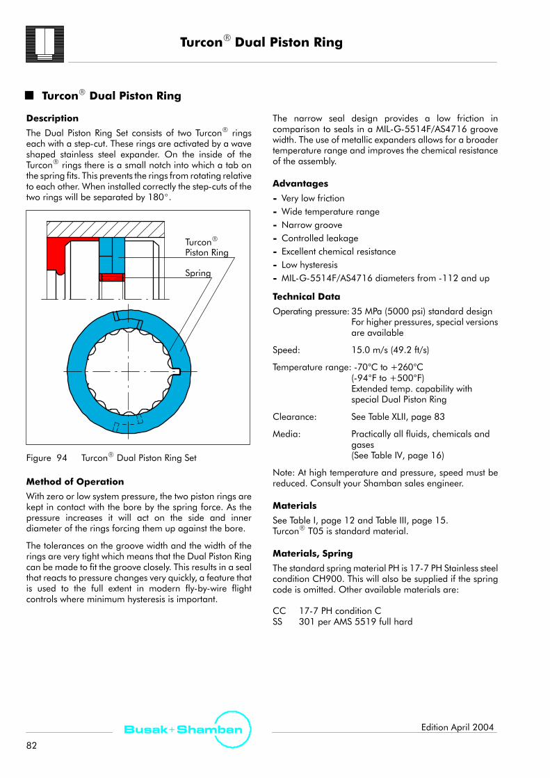
TurconR Dual Piston Ring
82
Busak+ Shamban Edition April 2004
TurconR Dual Piston Ring
Description
The Dual Piston Ring Set consists of two TurconR ringseach with a step-cut. These rings are activated by a waveshaped stainless steel expander. On the inside of theTurconR rings there is a small notch into which a tab onthe spring fits. This prevents the rings from rotating relativeto each other. When installed correctly the step-cuts of thetwo rings will be separated by 180_.
TurconR
Piston Ring
Spring
Figure 94 TurconR Dual Piston Ring Set
Method of Operation
With zero or low system pressure, the two piston rings arekept in contact with the bore by the spring force. As thepressure increases it will act on the side and innerdiameter of the rings forcing them up against the bore.
The tolerances on the groove width and the width of therings are very tight which means that the Dual Piston Ringcan be made to fit the groove closely. This results in a sealthat reacts to pressure changes very quickly, a feature thatis used to the full extent in modern fly-by-wire flightcontrols where minimum hysteresis is important.
The narrow seal design provides a low friction incomparison to seals in a MIL-G-5514F/AS4716 groovewidth. The use of metallic expanders allows for a broadertemperature range and improves the chemical resistanceof the assembly.
Advantages
- Very low friction- Wide temperature range- Narrow groove- Controlled leakage- Excellent chemical resistance- Low hysteresis- MIL-G-5514F/AS4716 diameters from -112 and up
Technical Data
Operating pressure: 35 MPa (5000 psi) standard designFor higher pressures, special versionsare available
Speed: 15.0 m/s (49.2 ft/s)
Temperature range: -70°C to +260°C(-94°F to +500°F)Extended temp. capability withspecial Dual Piston Ring
Clearance: See Table XLII, page 83
Media: Practically all fluids, chemicals andgases(See Table IV, page 16)
Note: At high temperature and pressure, speed must bereduced. Consult your Shamban sales engineer.
Materials
See Table I, page 12 and Table III, page 15.TurconR T05 is standard material.
Materials, Spring
The standard springmaterial PH is 17-7 PH Stainless steelcondition CH900. This will also be supplied if the springcode is omitted. Other available materials are:
CC 17-7 PH condition CSS 301 per AMS 5519 full hard

TurconR Dual Piston Ring
83
Busak+ ShambanEdition April 2004
Installation TurconR Dual Piston Ring Set, Series No. PF52 (Old Series No. S32152)
GR
D/2
øB
øA
Figure 95 Installation Drawing
Table XLII Groove Dimensions
D h
øABore Dia.
øBGroove Dia. G R D
Max.DashNo Inch mm Inch mm Inch Inch InchNo
+0.002-0.000
+0.05-0.00 ±0.004 ±0.10
Inch/
mm
Inch/
mm
Inch/
mm
112113114115116
0.6750.7380.8000.8630.925
17.1518.7520.3221.9223.50
0.4290.4280.4900.5530.615
10.9010.8712.4514.0515.62
210211212213214
215216217218219
220221222
0.9911.0531.1161.1781.241
1.3031.3661.4281.4911.553
1.6161.6781.741
25.1726.7528.3529.9231.52
33.1034.7036.2737.8739.45
41.0542.6244.22
0.6810.7430.8060.8680.931
0.9931.0560.9941.0571.119
1.1821.2441.307
17.3018.8720.4722.0523.65
25.2226.8225.2526.8528.42
30.0231.6033.20
.125|
.127
.010|
.020
.005
0.13
325326327328329
330331332333334
1.8671.9922.1182.2432.368
2.4932.6182.7432.8682.993
47.4250.6053.8056.9760.15
63.3266.5069.6772.8576.02
1.4331.5581.6841.8091.934
2.0592.1842.3092.4342.559
36.4039.5742.7745.9549.12
52.3055.4758.6561.8265.00
3.18|
3.23
0.25|
0.50
335336337338339
340
3.1183.2433.3683.4933.618
3.743
79.2082.3785.5588.7291.90
95.07
2.6842.8092.9343.0593.184
3.309
68.1771.3574.5277.7080.87
84.05
.006
0.15
D h
øABore Dia.
øBGroove Dia. G R D
Max.DashNo Inch mm Inch mm Inch Inch InchNo
+0.002-0.000
+0.05-0.00 ±0.004 ±0.10
Inch/
mm
Inch/
mm
Inch/
mm
341342
3.8683.993
98.25101.42
3.4343.559
87.2290.40 .125 .010
.0060.15
343344
345346347348349
4.1184.243
4.3684.4934.6184.7434.868
104.60107.77
110.95114.12117.30120.47123.65
3.5583.683
3.8083.9334.0584.1834.308
90.3793.55
96.7299.90103.07106.25109.42
.125|
.127
3.18|
3.23
.010|
.020
0.25|
0.50
.007
0.18
+0.003-0.000
+0.076-0.000 ±0.004 ±0.10
425426427428429
430431432433434
435436437438439
440441442443444
445446447
4.9745.0995.2245.3495.474
5.5995.7245.8495.9746.099
6.2246.3496.4746.7246.974
7.2247.4747.7247.9748.224
8.4748.9749.474
126.34129.51132.69135.86139.04
142.21145.39148.56151.74154.91
158.09161.26164.44170.79177.14
183.49189.84196.19202.54208.89
215.24227.94240.64
4.4144.5394.6644.7894.914
5.0395.1645.2895.4145.539
5.6645.7895.9146.1646.414
6.6646.9147.1647.4147.664
7.9148.4148.914
112.12115.29118.47121.64124.82
127.99131.17134.34137.52140.69
143.87147.04150.22156.57162.92
169.27175.62181.67188.32194.67
201.02213.72226.42
.188|
.190
4.78|
4.83
.010|
.020
0.25|
0.50
.008
0.20
Metric sizes.

TurconR Dual Piston Ring
84
Busak+ Shamban Edition April 2004
Series
Dash 343 - 349
Dash 425 - 447
Dash 112
Dash 113 - 216
Dash 217 - 342
Scale 3:1
Figure 96 Relationship Between the Profile Cross-Section
Ordering Example
Dual Piston Ring Series No. PF52
Dash No: 214
Material: T05
Seal part includesCertificate of conformance (C.C.)
Order No. PF52 T05A
Dash No.
Series No.
214
TurconR material code
S
Standard Expander material
0
0 = StandardK = a.r.t. (see note)
Groove standard
B
Note! For demanding dynamic applications an insert canbe added to the anti-rotation tab (a.r.t.) to provide greaterstrength. This option can be ordered by inserting a ”K” inthe 5th character of the part number.
Application Example
TurconR
Dual Piston RingTurconR
Scraper Ring
TurconR
Grooved Plus SealRIITurconR
HatsealRII
p
Figure 97 Rudder Actuator (Fly-By-Wire), Airbus A320
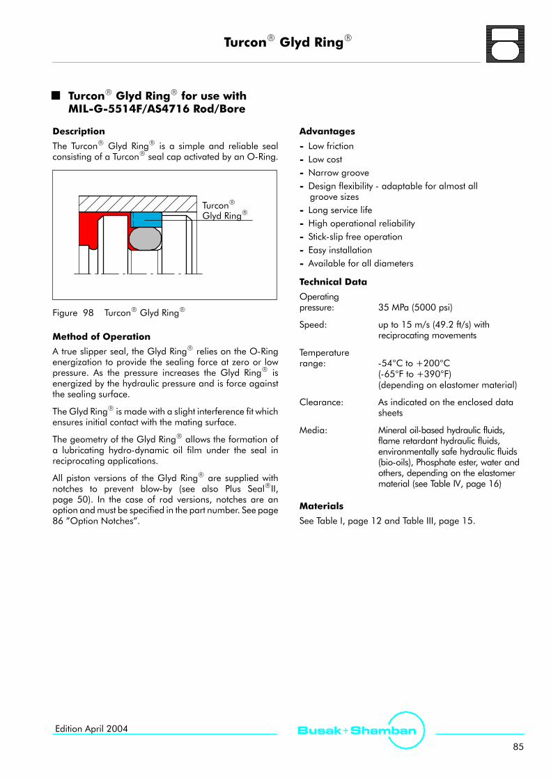
TurconR Glyd RingR
85
Busak+ ShambanEdition April 2004
TurconR Glyd RingR for use withMIL-G-5514F/AS4716 Rod/Bore
Description
The TurconR Glyd RingR is a simple and reliable sealconsisting of a TurconR seal cap activated by an O-Ring.
TurconR
Glyd RingR
Figure 98 TurconR Glyd RingR
Method of Operation
A true slipper seal, the Glyd RingR relies on the O-Ringenergization to provide the sealing force at zero or lowpressure. As the pressure increases the Glyd RingR isenergized by the hydraulic pressure and is force againstthe sealing surface.
The Glyd RingR is made with a slight interference fit whichensures initial contact with the mating surface.
The geometry of the Glyd RingR allows the formation ofa lubricating hydro-dynamic oil film under the seal inreciprocating applications.
All piston versions of the Glyd RingR are supplied withnotches to prevent blow-by (see also Plus SealRII,page 50). In the case of rod versions, notches are anoption andmust be specified in the part number. See page86 ”Option Notches”.
Advantages
- Low friction- Low cost- Narrow groove- Design flexibility - adaptable for almost allgroove sizes
- Long service life- High operational reliability- Stick-slip free operation- Easy installation- Available for all diameters
Technical Data
Operatingpressure: 35 MPa (5000 psi)
Speed: up to 15 m/s (49.2 ft/s) withreciprocating movements
Temperaturerange: -54°C to +200°C
(-65°F to +390°F)(depending on elastomer material)
Clearance: As indicated on the enclosed datasheets
Media: Mineral oil-based hydraulic fluids,flame retardant hydraulic fluids,environmentally safe hydraulic fluids(bio-oils), Phosphate ester, water andothers, depending on the elastomermaterial (see Table IV, page 16)
Materials
See Table I, page 12 and Table III, page 15.

TurconR Glyd RingR
86
Busak+ Shamban Edition April 2004
Series
The Glyd RingR is designed to mate with standardMIL-G-5514F/AS4716 rod or bore sizes, however thegroove dimensions are a Shamban design standard.
Scale 3:1Dash 007 - 010
Dash 011 - 028
Dash 110 - 149
Dash 210 - 247
Dash 325 - 352
Dash 428 - 460
Figure 99 Relationship Between the ProfileCross-Section Series No. PG28 and RG27
Ordering Example
TurconR Glyd RingR Series No. PG28 with notch
Dash No: 214
Material: T05 (standard), see Table I, page 12.
Seal part includescertificate of conformance (C.C.)
Order No. PG28 T05A
Dash No.
Series No.
214
TurconR material code
0
Groove standard
B
0 = Notch (standard)W = No notch
Note: O-Rings are ordered separately. Sizes can befound in Table XLIII, page 87 and Table XLIV, page 89.
Option Notches: Piston seals are always delivered asstandard with notch. To omit notch, change 5th characterto ”W”. Ex. PG28W.Rod seals are always delivered as standard withoutnotch. To include notch, change 5th character to ”N”.Ex. RG27N
Application Example
Figure 100 Typical Spool Valve
The Glyd RingR offers space savings and easy assemblyin spool valves.
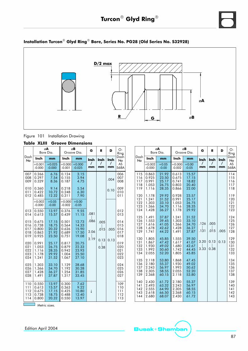
TurconR Glyd RingR
87
Busak+ ShambanEdition April 2004
Installation TurconR Glyd RingR Bore, Series No. PG28 (Old Series No. S32928)
G
D/2 max
R øB
øA
Figure 101 Installation Drawing
Table XLIII Groove Dimensions
D h
øABore Dia.
øBGroove Dia. G R D O-
RingD hDash
No Inch mm Inch mm Inch Inch Inch
gDashNoNo
+0.001-0.000
+0.025-0.000
+0.000-0.001
+0.000-0.025
Inch/
mm
Inch/
mm
Inch/
mm
NoAS
568A
007008009
010011012
0.2660.2970.329
0.3600.4220.485
6.767.548.36
9.1410.7212.32
0.1240.1550.187
0.2180.2480.311
3.153.944.75
5.546.307.90
.004
0.10
006007008
009010011
+0.002-0.000
+0.05-0.00
+0.000-0.002
+0.00-0.05
013014
015016017018019
020021022023024
025026027028
0.5500.613
0.6750.7380.8000.8630.925
0.9911.0531.1161.1781.241
1.3031.3661.4281.491
13.9715.57
17.1518.7520.3221.9223.50
25.1726.7528.3529.9231.52
33.1034.7036.2737.87
0.3760.439
0.5010.5640.6260.6890.751
0.8170.8790.9421.0041.067
1.1291.1921.2541.317
9.5511.15
12.7314.3315.9017.5019.08
20.7522.3323.9325.5027.10
28.6830.2831.8533.45
.081|
.086
2.06|
2.19
.005|
.015
0.13|
0.38
.005
0.13
012013
014015016017018
019020021022023
024025026027
110111112113114
0.5500.6130.6750.7380.800
13.9715.5717.1518.7520.32
0.3000.3630.4250.4880.550
7.629.2210.8012.4013.97
↓
109110111112113
D h
øABore Dia.
øBGroove Dia. G R D O-
RingD hDash
No Inch mm Inch mm Inch Inch Inch
gDashNoNo
+0.002-0.000
+0.05-0.00
+0.000-0.002
+0.00-0.05
Inch/
mm
Inch/
mm
Inch/
mm
NoAS
568A
115116117118119
120121122123124
125126127128129
130131132133134
135136137138139
140141142143144
0.8630.9250.9911.0531.116
1.1781.2411.3031.3661.428
1.4911.5531.6161.6781.741
1.8051.8671.9301.9922.055
2.1182.1802.2432.3052.368
2.4302.4932.5552.6182.680
21.9223.5025.1726.7528.35
29.9231.5233.1034.7036.27
37.8739.4541.0542.6244.22
45.8547.4249.0250.6052.20
53.8055.3756.9758.5560.15
61.7263.3264.9066.5068.07
0.6130.6750.7410.8030.866
0.9280.9911.0531.1161.178
1.2411.3031.3661.4281.491
1.5551.6171.6801.7421.805
1.8681.9301.9932.0552.118
2.1802.2432.3052.3682.430
15.5717.1518.8220.4022.00
23.5725.1726.7528.3529.92
31.5233.1034.7036.2737.87
39.5041.0742.6744.4545.85
47.4549.0250.6252.2053.80
55.3756.9758.5560.1561.72
.126|
.131
3.20|
3.33
.005|
.015
0.13|
0.38
.005
0.13
114115116117118
119120121122123
124125126127128
129130131132133
134135136137138
139140141142143
Metric sizes.
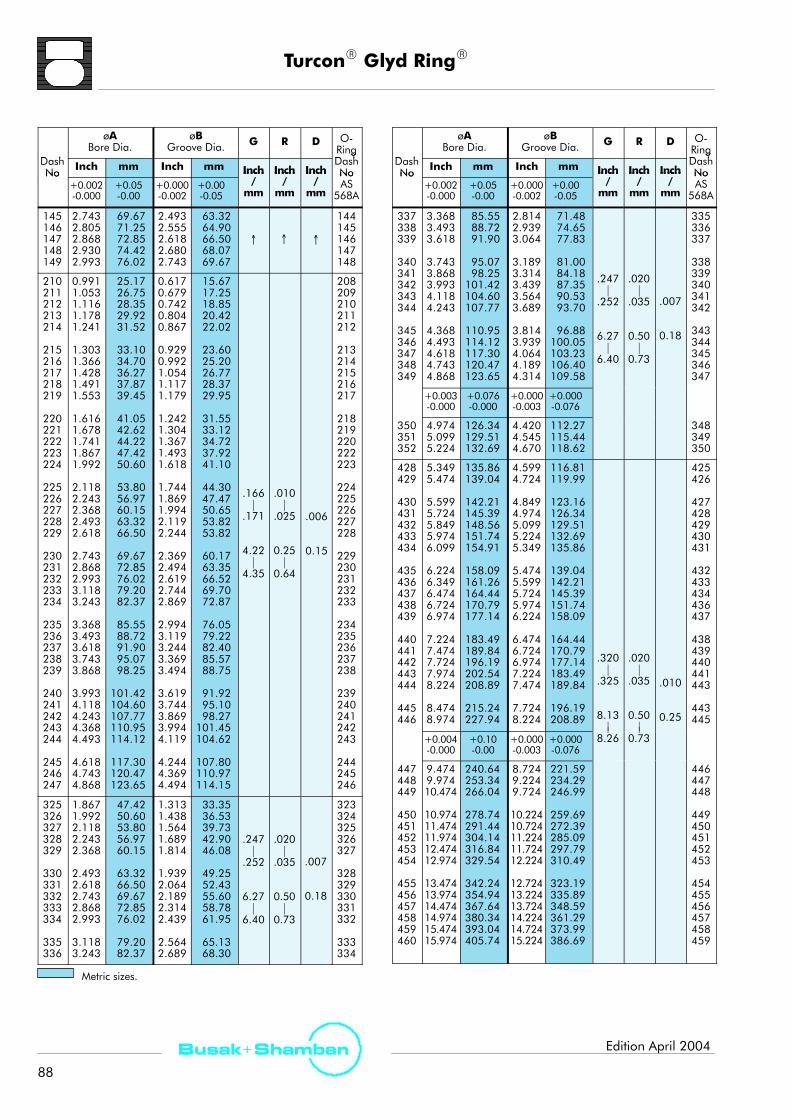
TurconR Glyd RingR
88
Busak+ Shamban Edition April 2004
D h
øABore Dia.
øBGroove Dia. G R D O-
RingD hDash
No Inch mm Inch mm Inch Inch Inch
gDashNoNo
+0.002-0.000
+0.05-0.00
+0.000-0.002
+0.00-0.05
Inch/
mm
Inch/
mm
Inch/
mm
NoAS
568A
145146147148149
2.7432.8052.8682.9302.993
69.6771.2572.8574.4276.02
2.4932.5552.6182.6802.743
63.3264.9066.5068.0769.67
↑ ↑ ↑
144145146147148
210211212213214
215216217218219
220221222223224
225226227228229
230231232233234
235236237238239
240241242243244
245246247
0.9911.0531.1161.1781.241
1.3031.3661.4281.4911.553
1.6161.6781.7411.8671.992
2.1182.2432.3682.4932.618
2.7432.8682.9933.1183.243
3.3683.4933.6183.7433.868
3.9934.1184.2434.3684.493
4.6184.7434.868
25.1726.7528.3529.9231.52
33.1034.7036.2737.8739.45
41.0542.6244.2247.4250.60
53.8056.9760.1563.3266.50
69.6772.8576.0279.2082.37
85.5588.7291.9095.0798.25
101.42104.60107.77110.95114.12
117.30120.47123.65
0.6170.6790.7420.8040.867
0.9290.9921.0541.1171.179
1.2421.3041.3671.4931.618
1.7441.8691.9942.1192.244
2.3692.4942.6192.7442.869
2.9943.1193.2443.3693.494
3.6193.7443.8693.9944.119
4.2444.3694.494
15.6717.2518.8520.4222.02
23.6025.2026.7728.3729.95
31.5533.1234.7237.9241.10
44.3047.4750.6553.8253.82
60.1763.3566.5269.7072.87
76.0579.2282.4085.5788.75
91.9295.1098.27101.45104.62
107.80110.97114.15
.166|
.171
4.22|
4.35
.010|
.025
0.25|
0.64
.006
0.15
208209210211212
213214215216217
218219220222223
224225226227228
229230231232233
234235236237238
239240241242243
244245246
325326327328329
330331332333334
335336
1.8671.9922.1182.2432.368
2.4932.6182.7432.8682.993
3.1183.243
47.4250.6053.8056.9760.15
63.3266.5069.6772.8576.02
79.2082.37
1.3131.4381.5641.6891.814
1.9392.0642.1892.3142.439
2.5642.689
33.3536.5339.7342.9046.08
49.2552.4355.6058.7861.95
65.1368.30
.247|
.252
6.27|
6.40
.020|
.035
0.50|
0.73
.007
0.18
323324325326327
328329330331332
333334
D h
øABore Dia.
øBGroove Dia. G R D O-
RingD hDash
No Inch mm Inch mm Inch Inch Inch
gDashNoNo
+0.002-0.000
+0.05-0.00
+0.000-0.002
+0.00-0.05
Inch/
mm
Inch/
mm
Inch/
mm
NoAS
568A
337338339
340341342343344
345346347348349
3.3683.4933.618
3.7433.8683.9934.1184.243
4.3684.4934.6184.7434.868
85.5588.7291.90
95.0798.25101.42104.60107.77
110.95114.12117.30120.47123.65
2.8142.9393.064
3.1893.3143.4393.5643.689
3.8143.9394.0644.1894.314
71.4874.6577.83
81.0084.1887.3590.5393.70
96.88100.05103.23106.40109.58
.247|
.252
6.27|
6.40
.020|
.035
0.50|
0.73
.007
0.18
335336337
338339340341342
343344345346347
+0.003-0.000
+0.076-0.000
+0.000-0.003
+0.000-0.076
350351352
4.9745.0995.224
126.34129.51132.69
4.4204.5454.670
112.27115.44118.62
348349350
428429
430431432433434
435436437438439
440441442443444
445446
5.3495.474
5.5995.7245.8495.9746.099
6.2246.3496.4746.7246.974
7.2247.4747.7247.9748.224
8.4748.974
135.86139.04
142.21145.39148.56151.74154.91
158.09161.26164.44170.79177.14
183.49189.84196.19202.54208.89
215.24227.94
4.5994.724
4.8494.9745.0995.2245.349
5.4745.5995.7245.9746.224
6.4746.7246.9747.2247.474
7.7248.224
116.81119.99
123.16126.34129.51132.69135.86
139.04142.21145.39151.74158.09
164.44170.79177.14183.49189.84
196.19208.89
.320|
.325
8.13|
.020|
.035
0.50|
.010
0.25
425426
427428429430431
432433434436437
438439440441443
443445
+0.004-0.000
+0.10-0.00
+0.000-0.003
+0.000-0.076
|8.26
|0.73
447448449
450451452453454
455456457458459460
9.4749.97410.474
10.97411.47411.97412.47412.974
13.47413.97414.47414.97415.47415.974
240.64253.34266.04
278.74291.44304.14316.84329.54
342.24354.94367.64380.34393.04405.74
8.7249.2249.724
10.22410.72411.22411.72412.224
12.72413.22413.72414.22414.72415.224
221.59234.29246.99
259.69272.39285.09297.79310.49
323.19335.89348.59361.29373.99386.69
446447448
449450451452453
454455456457458459
Metric sizes.

TurconR Glyd RingR
89
Busak+ ShambanEdition April 2004
Installation TurconR Glyd RingR Rod, Series No. RG27 (Old Series No. S32927)
GR
D/2 max
øA
øB
Figure 102 Installation Drawing
Table XLIV Groove Dimensions
D h
øBRod Dia.
øAGroove Dia. G R D O-
RingD hDash
No Inch mm Inch mm Inch Inch InchDashNoNo
+0.000-0.001
+0.000-0.025
+0.001-0.000
+0.025-0.000
Inch/
mm
Inch/
mm
Inch/
mm
NoAS
568A
006007008009
010011012
0.1230.1540.1850.217
0.2480.3100.373
3.123.914.705.51
6.307.879.47
0.2590.2900.3210.353
0.4220.4840.547
6.587.378.158.97
10.7212.2913.89
.004
0.10
007008009010
011012013
+0.000-0.002
+0.00-0.05
+0.002-0.000
+0.05-0.00
013014
015016017018019
020021022023024
025026027028
0.4350.498
0.5600.6230.6850.7480.810
0.8730.9350.9981.0601.123
1.1851.2481.3101.373
11.0512.65
14.2215.8217.4019.0020.57
22.1723.7525.3526.9228.52
30.1031.7033.2734.87
0.6090.672
0.7340.7970.8590.9220.984
1.0471.1091.1721.2341.297
1.3591.4221.4841.547
15.4717.07
18.6420.2421.8223.4224.99
26.5928.1729.7731.3432.94
34.5236.1237.6939.29
.081|
.086
2.06|
2.19
.005|
.015
0.13|
0.38
.005
0.13
014015
016017018019020
021022023024025
026027028028
110111112113
0.3730.4350.4980.560
9.4711.0512.6514.22
0.6230.6850.7480.810
15.8217.4019.0020.57
↓
111112113114
D h
øBRod Dia.
øAGroove Dia. G R D O-
RingD hDash
No Inch mm Inch mm Inch Inch InchDashNoNo
+0.000-0.002
+0.00-0.05
+0.002-0.000
+0.05-0.00
Inch/
mm
Inch/
mm
Inch/
mm
NoAS
568A
114
115116117118119
120121122123124
125126127128129
130131132133134
135136137138139
140141142
0.623
0.6850.7480.8100.8730.935
0.9981.0601.1231.1851.248
1.3101.3731.4351.4981.560
1.6231.6851.7481.8101.873
1.9301.9982.0612.1232.186
2.2482.3112.373
15.82
17.4019.0020.5722.1723.75
25.3526.9228.5230.1031.70
33.2734.8736.4538.0539.62
41.2242.8044.4045.9747.57
49.1750.7552.3553.9255.52
57.1058.7060.27
0.873
0.9350.9981.0601.1231.185
1.2481.3101.3731.4351.498
1.5601.6231.6851.7481.810
1.8731.9351.9982.0602.123
2.1862.2482.3112.3732.436
2.4982.5612.623
22.17
23.7525.3526.9228.5230.10
31.7033.2734.8736.4538.05
39.6241.2242.8044.4045.97
47.5749.1550.7552.3253.92
55.5257.1058.7060.2761.87
63.4565.0566.62
.126|
.131
3.20|
3.33
.005|
.015
0.13|
0.38
.005
0.13
115
116117118119120
121122123124125
126127128129130
131132133134135
136137138139140
141142143
Metric sizes.
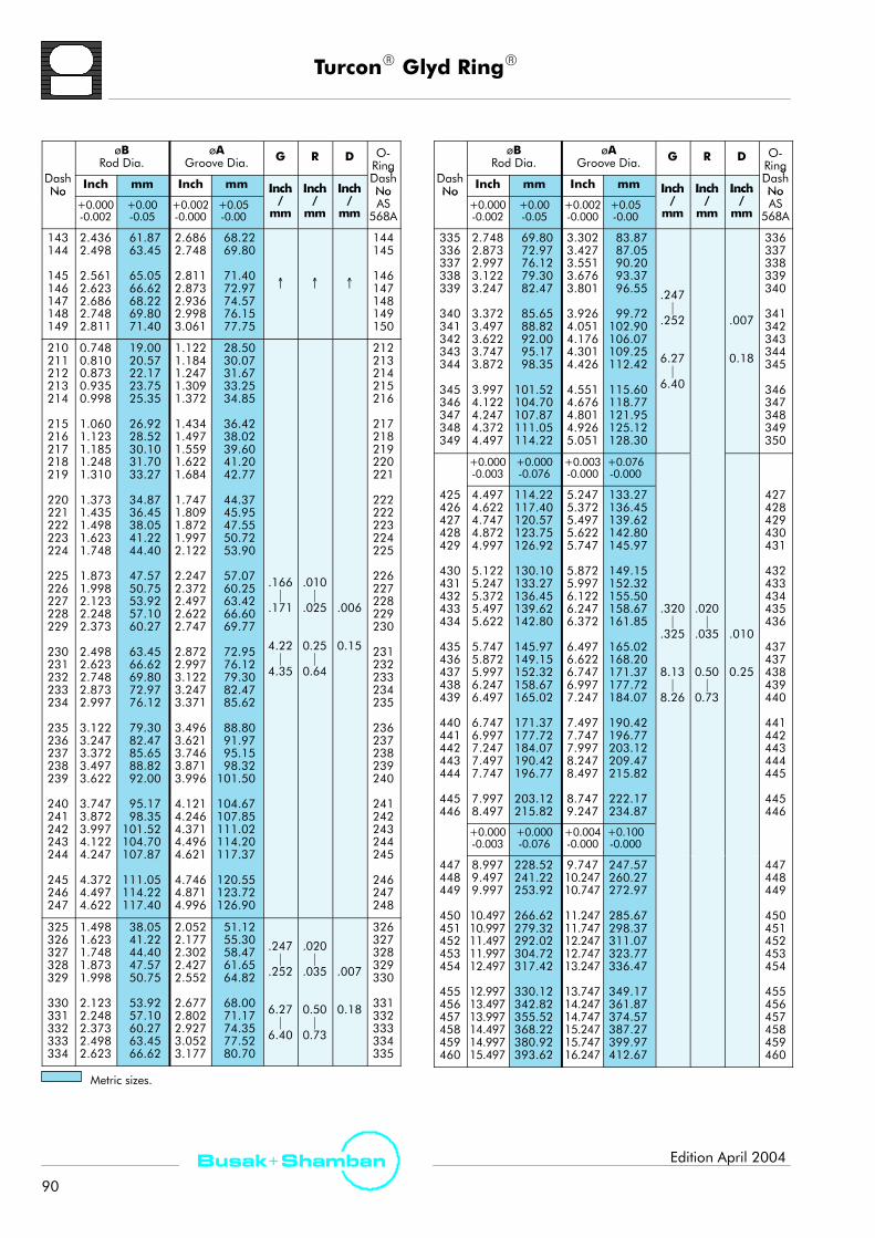
TurconR Glyd RingR
90
Busak+ Shamban Edition April 2004
D h
øBRod Dia.
øAGroove Dia. G R D O-
RingD hDash
No Inch mm Inch mm Inch Inch Inch
gDashNoNo
+0.000-0.002
+0.00-0.05
+0.002-0.000
+0.05-0.00
Inch/
mm
Inch/
mm
Inch/
mm
NoAS
568A
143144
145146147148149
2.4362.498
2.5612.6232.6862.7482.811
61.8763.45
65.0566.6268.2269.8071.40
2.6862.748
2.8112.8732.9362.9983.061
68.2269.80
71.4072.9774.5776.1577.75
↑ ↑ ↑
144145
146147148149150
210211212213214
215216217218219
220221222223224
225226227228229
230231232233234
235236237238239
240241242243244
245246247
0.7480.8100.8730.9350.998
1.0601.1231.1851.2481.310
1.3731.4351.4981.6231.748
1.8731.9982.1232.2482.373
2.4982.6232.7482.8732.997
3.1223.2473.3723.4973.622
3.7473.8723.9974.1224.247
4.3724.4974.622
19.0020.5722.1723.7525.35
26.9228.5230.1031.7033.27
34.8736.4538.0541.2244.40
47.5750.7553.9257.1060.27
63.4566.6269.8072.9776.12
79.3082.4785.6588.8292.00
95.1798.35101.52104.70107.87
111.05114.22117.40
1.1221.1841.2471.3091.372
1.4341.4971.5591.6221.684
1.7471.8091.8721.9972.122
2.2472.3722.4972.6222.747
2.8722.9973.1223.2473.371
3.4963.6213.7463.8713.996
4.1214.2464.3714.4964.621
4.7464.8714.996
28.5030.0731.6733.2534.85
36.4238.0239.6041.2042.77
44.3745.9547.5550.7253.90
57.0760.2563.4266.6069.77
72.9576.1279.3082.4785.62
88.8091.9795.1598.32101.50
104.67107.85111.02114.20117.37
120.55123.72126.90
.166|
.171
4.22|
4.35
.010|
.025
0.25|
0.64
.006
0.15
212213214215216
217218219220221
222222223224225
226227228229230
231232233234235
236237238239240
241242243244245
246247248
325326327328329
330331332333334
1.4981.6231.7481.8731.998
2.1232.2482.3732.4982.623
38.0541.2244.4047.5750.75
53.9257.1060.2763.4566.62
2.0522.1772.3022.4272.552
2.6772.8022.9273.0523.177
51.1255.3058.4761.6564.82
68.0071.1774.3577.5280.70
.247|
.252
6.27|
6.40
.020|
.035
0.50|
0.73
.007
0.18
326327328329330
331332333334335
D h
øBRod Dia.
øAGroove Dia. G R D O-
RingD hDash
No Inch mm Inch mm Inch Inch Inch
gDashNoNo
+0.000-0.002
+0.00-0.05
+0.002-0.000
+0.05-0.00
Inch/
mm
Inch/
mm
Inch/
mm
NoAS
568A
335336337338339
340341342343344
345346347348349
2.7482.8732.9973.1223.247
3.3723.4973.6223.7473.872
3.9974.1224.2474.3724.497
69.8072.9776.1279.3082.47
85.6588.8292.0095.1798.35
101.52104.70107.87111.05114.22
3.3023.4273.5513.6763.801
3.9264.0514.1764.3014.426
4.5514.6764.8014.9265.051
83.8787.0590.2093.3796.55
99.72102.90106.07109.25112.42
115.60118.77121.95125.12128.30
.247|
.252
6.27|
6.40
.007
0.18
336337338339340
341342343344345
346347348349350
+0.000-0.003
+0.000-0.076
+0.003-0.000
+0.076-0.000
425426427428429
430431432433434
435436437438439
440441442443444
445446
4.4974.6224.7474.8724.997
5.1225.2475.3725.4975.622
5.7475.8725.9976.2476.497
6.7476.9977.2477.4977.747
7.9978.497
114.22117.40120.57123.75126.92
130.10133.27136.45139.62142.80
145.97149.15152.32158.67165.02
171.37177.72184.07190.42196.77
203.12215.82
5.2475.3725.4975.6225.747
5.8725.9976.1226.2476.372
6.4976.6226.7476.9977.247
7.4977.7477.9978.2478.497
8.7479.247
133.27136.45139.62142.80145.97
149.15152.32155.50158.67161.85
165.02168.20171.37177.72184.07
190.42196.77203.12209.47215.82
222.17234.87
.320|
.325
8.13|
8.26
.020|
.035
0.50|
0.73
.010
0.25
427428429430431
432433434435436
437437438439440
441442443444445
445446
+0.000-0.003
+0.000-0.076
+0.004-0.000
+0.100-0.000
447448449
450451452453454
455456457458459460
8.9979.4979.997
10.49710.99711.49711.99712.497
12.99713.49713.99714.49714.99715.497
228.52241.22253.92
266.62279.32292.02304.72317.42
330.12342.82355.52368.22380.92393.62
9.74710.24710.747
11.24711.74712.24712.74713.247
13.74714.24714.74715.24715.74716.247
247.57260.27272.97
285.67298.37311.07323.77336.47
349.17361.87374.57387.27399.97412.67
447448449
450451452453454
455456457458459460
Metric sizes.

TurconR StepsealRK
91
Busak+ ShambanEdition April 2004
TurconR StepsealRK*For use with MIL-Standard Rod/Bore
Description
The sealing of piston rods places the highest demands onoperational safety and environmental protection inhydraulic engineering.
Rod sealing systems must exhibit no dynamic leakage tothe atmosphere under all operating conditions and mustbe completely leak tight when the machine is in a staticcondition.
Furthermore, they should achieve a high degree ofmechanical efficiency through low friction and be easy toinstall in small grooves. Costs and service life must meetthe high expectations of the operator.
The piston rod seal, TurconR StepsealRK, developed byShamban comes closest to satisfying these idealdemands. Already in use for several decades, this seal isstill a technically outstanding seal element due to thecontinuous innovative development of the design and ofthe TurconR materials.
With the introduction of the StepsealRK it became possibleto arrange several seals one behind the other, thusallowing tandem seal configurations to be created withoutany build-up of intermediate pressure.
The single-acting seal element is made of high-gradeTurconR materials with outstanding sliding and wearresistance properties. It is installed in grooves to Shambanstandards using an O-Ring as the energizing element.
p
TurconR
StepsealRK
Figure 103 TurconR StepsealRK
* Patent-No. P 32 25 906
Method of Operation
The sealing mechanism of the StepsealRK (Figure 103)is based on the hydrodynamic properties of the seal. Thespecially formed seal edge has a steep contact pressuregradient on the high pressure side and a shallow contactpressure gradient on the low pressure side. This ensuresthat the fluid film adhering to the piston rod is returned tothe high pressure chamber on the return stroke of the rod.This prevents themicro-fluid layer, that is carried out of thehigh pressure chamber when the piston rod is extended,from causing leaks.
This return delivery property prevents the build-up ofinterstage pressure normally associated with tandem sealconfigurations (Figure 104). Interstage pressure dependson the system pressure speed, the stroke length and thegroove design.
ppiSEF
: System pressure: Inter seal pressure: Out stroke: In stroke: Lubrication film
p
F
pi
p
E
S
Figure 104 Pressure Distribution in Tandem Installation

TurconR StepsealRK
92
Busak+ Shamban Edition April 2004
Design Instructions
In many applications, tandem unvented sealing systemsare required. Figure 105 shows such a tandemconfiguration utilizing the StepsealRK. The use of tandemStepsealR increases functional reliability.
p
TurconR StepsealR KTurconR
ExcluderRDC
Figure 105 TurconR StepsealRK in TandemConfiguration
In this configuration it must be noted that a sufficientlylarge space is designed between the seals to take thehydraulic fluid, as shown in Figure 123, page 104.
Depending on the application and the operating conditions,the combination of different materials offers an improvementin the sealing efficiency and the service life of the system, e.g.in hydraulic cylinders subject to high loads and under roughoperating conditions.
StepsealR K elements should always be used in combinationwith a double acting scraper to provide an optimum sealingeffect. The ExcluderR DC is well suited for suchapplications. For further details, please see ExcluderR andScraper section on page 104.
Advantages
- High static and dynamic sealing effect- Low friction, and high efficiency- Stick-slip free operation- High abrasion resistance, high operational reliability- Simple groove design- Wide range of application temperatures and highresistance to chemicals, depending on the choice ofelastomer material
- Available for all diameters up to 3000 mm (10 ft.)
Technical DataOperating pressure: up to 35 MPa (5000 psi)Speed: up to 15 m/s (49.2 ft/s) with
reciprocating movements,frequency up to 5 Hz
Temperature: -54°C to +200°C(-65°F to +390°F)(depending on elastomermaterial)
Media: Mineral oil-based hydraulic fluids,flame retardant hydraulic fluids,environmentally safe hydraulicfluids (bio-oils), water and others,depending on the elastomermaterial(see Table IV, page 16)
Gap width: The maximum permissible radialgap D/2max is shown in Table XLVand XLVI, pages 94 - 97,as a function of the operatingpressure and functional diameter.
Materials
See Table I, page 12.

TurconR StepsealRK
93
Busak+ ShambanEdition April 2004
Series
The StepsealRK is available in most MIL-G-5514F/AS4716 bore or rod dimensions, and also for a numberof non-MIL spec. grooves. Please consult your Shambansales engineer for non-standard sizes.
000 Series
100 Series
200 Series
300 Series
400 Series
Scale 3:1
Figure 106 Relationship Between the ProfileCross-Sections
Ordering Example
TurconR StepsealRK,Rod Seal, Series No. RSA7
Dash No: 214
Material: T05see Table I, Page 12
Seal part includescertificate of conformance (C.C.)
Order No. RSA7 T05A
Dash No.
Series No.
214
TurconR material code
0
Groove standard
B
0 = standard
Note: O-Rings must be ordered separately. Sizes can befound in Table XLV and Table XLVI, pages 94 - 97.
Case Story
p
TurconR
StepsealRKTurconR
HatsealRII
Figure 107 EH 101 Rotor Control TurconR HatsealRIIand TurconR StepsealRK
Problem
Limited life resulting from pressure impulsing.
Solution
A sealing system combining the StepsealRK andHatsealRII has optimized seal life.

TurconR StepsealRK
94
Busak+ Shamban Edition April 2004
Installation TurconR StepsealRK Bore, Series No. PSA8 (Old Series No. S34768)
G
D/2 max
R øB
øA
Figure 108 Installation Drawing
Table XLV Groove Dimensions
D h
øABore Dia.
øBGroove Dia. G R D O-
RingD hDash
No Inch mm Inch mm Inch Inch Inch
gDashNoNo
+0.001-0.000
+0.025-0.000
+0.000-0.001
+0.000-0.025
Inch/
mm
Inch/
mm
Inch/
mm
NoAS
568A
011012
0.4220.485
10.7212.32
0.2480.311
6.307.90
.0040.10
010011
+0.002-0.000
+0.05-0.00
+0.000-0.002
+0.00-0.05
013014
015016017018019
020021022023024
025026027028
0.5500.613
0.6750.7380.8000.8630.925
0.9911.0531.1161.1781.241
1.3031.3661.4281.491
13.9715.57
17.1518.7520.3221.9223.50
25.1726.7528.3529.9231.52
33.1034.7036.2737.87
0.3760.439
0.5010.5640.6260.6890.751
0.8170.8790.9421.0041.067
1.1291.1921.2541.317
9.5511.15
12.7314.3315.9017.5019.08
20.7522.3323.9325.5027.10
28.6830.2831.8533.45
.081|
.086
2.06|
2.19.005|
.015
0.13|
0.38
.005
0.13
012013
014015016017018
019020021022023
024025026027
110111112113114
115116117118119
0.5500.6130.6750.7380.800
0.8630.9250.9911.0531.116
13.9715.5717.1518.7520.32
21.9223.5025.1726.7528.35
0.3000.3630.4250.4880.550
0.6130.6750.7410.8030.866
7.629.2210.8012.4013.97
15.5717.1518.8220.4022.00
.126|
.131
3.20|
3.33
109110111112113
114115116117118
Metric sizes.
D h
øABore Dia.
øBGroove Dia. G R D O-
RingD hDash
No Inch mm Inch mm Inch Inch Inch
gDashNoNo
+0.002-0.000
+0.05-0.00
+0.000-0.002
+0.00-0.05
Inch/
mm
Inch/
mm
Inch/
mm
NoAS
568A
120121122123124
125126127128129
1.1781.2411.3031.3661.428
1.4911.5531.6161.6781.741
29.9231.5233.1034.7036.27
37.8739.4541.0542.6244.22
0.9280.9911.0531.1161.178
1.2411.3031.3661.4281.491
23.5725.1726.7528.3529.92
31.5233.1034.7036.2737.87
.005
0.13
119120121122123
124125126127128
130131132133134
135136137138139
140
1.8051.8671.9301.9922.055
2.1182.1802.2432.3052.368
2.430
45.8547.4249.0250.6052.20
53.8055.3756.9758.5560.15
61.72
1.5551.6171.6801.7421.805
1.8681.9301.9932.0552.118
2.180
39.5041.0742.6744.4545.85
47.4549.0250.6252.2053.80
55.37
.126|
.131
3.20|
3.33
.005|
.015
0.13|
0.38
.006
0.15
129130131132133
134135136137138
139
141142143144
145146147148149
2.4932.5552.6182.680
2.7432.8052.8682.9302.993
63.3264.9066.5068.07
69.6771.2572.8574.4276.02
2.2432.3052.3682.430
2.4932.5552.6182.6802.743
56.9758.5560.1561.72
63.3264.9066.5068.0769.67
.007
0.18
140141142143
144145146147148

TurconR StepsealRK
95
Busak+ ShambanEdition April 2004
D h
øABore Dia.
øBGroove Dia. G R D O-
RingD hDash
No Inch mm Inch mm Inch Inch Inch
gDashNoNo
+0.002-0.000
+0.05-0.00
+0.000-0.002
+0.00-0.05
Inch/
mm
Inch/
mm
Inch/
mm
NoAS
568A
210211212213214
215216217218219
220221222
0.9911.0531.1161.1781.241
1.3031.3661.4281.4911.553
1.6161.6781.741
25.1726.7528.3529.9231.52
33.1034.7036.2737.8739.45
41.0542.6244.22
0.6170.6790.7420.8040.867
0.9290.9921.0541.1171.179
1.2421.3041.367
15.6717.2518.8520.4222.02
23.6025.2026.7728.3729.95
31.5533.1234.72
.005
0.13
208209210211212
213214215216217
218219220
223224
225226227
1.8671.992
2.1182.2432.368
47.4250.60
53.8056.9760.15
1.4931.618
1.7441.8691.994
37.9241.10
44.3047.4750.65
.166|
171
.010|
025
.006
0.15
222223
224225226
228229
230231232233234
235236237238239
240241242243
2.4932.618
2.7432.8682.9933.1183.243
3.3683.4933.6183.7433.868
3.9934.1184.2434.368
63.3266.50
69.6772.8576.0279.2082.37
85.5588.7291.9095.0798.25
101.42104.60107.77110.95
2.1192.244
2.3692.4942.6192.7442.869
2.9943.1193.2443.3693.494
3.6193.7443.8693.994
53.8257.00
60.1763.3566.5269.7072.87
76.0579.2282.4085.5788.75
91.9295.1098.27101.45
.171
4.22|
4.35
.025
0.25|
0.64
.007
0.18
227228
229230231232233
234235236237238
239240241242
244
245246247
4.493
4.6184.7434.868
114.12
117.30120.47123.65
4.119
4.2444.3694.494
104.62
107.80110.97114.15
.008
0.20
243
244245246
325326327328329
1.8671.9922.1182.2432.368
47.4250.6053.8056.9760.15
1.3131.4381.5641.6891.814
33.3536.5339.7342.9046.08
.006
0.15
323324325326327
330331332333334
335336337338339
340
2.4932.6182.7432.8682.993
3.1183.2433.3683.4933.618
3.743
63.3266.5069.6772.8576.02
79.2082.3785.5588.7291.90
95.07
1.9392.0642.1892.3142.439
2.5642.6892.8142.9393.064
3.189
49.2552.4355.6058.7861.95
65.1368.3071.4874.6577.83
81.00
.247|
.252
6.27|
6.40
.020|
.035
0.50|
0.73
.007
0.18
328329330331332
333334335336337
338
D h
øABore Dia.
øBGroove Dia. G R D O-
RingD hDash
No Inch mm Inch mm Inch Inch Inch
gDashNoNo
+0.002-0.000
+0.05-0.00
+0.000-0.002
+0.00-0.05
Inch/
mm
Inch/
mm
Inch/
mm
NoAS
568A
341342343344
345
3.8683.9934.1184.243
4.368
98.25101.42104.60107.77
110.95
3.3143.4393.5643.689
3.814
84.1887.3590.5393.70
96.88 .247|
.020|
.007
0.18
339340341342
343
346347348349
4.4934.6184.7434.868
114.12117.30120.47123.65
3.9394.0644.1894.314
100.05103.23106.40109.58
|.252
6.27|
|.035
0.50|
.008
344345346347
+0.003-0.000
+0.076-0.000
+0.000-0.003
+0.000-0.076
|6.40
|0.73
008
0.20350351352
4.9745.0995.224
126.34129.51132.69
4.4204.5454.670
112.27115.44118.62
0.20348349350
428429
430431432433434
435436437438439
440441442443444
445
5.3495.474
5.5995.7245.8495.9746.099
6.2246.3496.4746.7246.974
7.2247.4747.7247.9748.224
8.474
135.86139.04
142.21145.39148.56151.74154.91
158.09161.26164.44170.79177.14
183.49189.84196.19202.54208.89
215.24
4.5994.724
4.8494.9745.0995.2245.349
5.4745.5995.7245.9746.224
6.4746.7246.9747.2247.474
7.724
116.81119.99
123.16126.34129.51132.69135.86
139.04142.21145.39151.74158.09
164.44170.79177.14183.49189.84
196.19
.320|
.325
.020|
.035
.009
0.23
425426
427428429430431
432433434436437
438439440441443
443
446 8.974 227.94 8.224 208.89.325
8.13|
8 26
.035
0.50|
0 73
.010
0.25
445
+0.004-0.000
+0.10-0.00
+0.000-0.003
+0.000-0.076
8.26 0.73
447448449
450451452453454
455456457458459
460
9.4749.97410.474
10.97411.47411.97412.47412.974
13.47413.97414.47414.97415.474
15.974
240.64253.34266.04
278.74291.44304.14316.84329.54
342.24354.94367.64380.34393.04
405.74
8.7249.2249.724
10.22410.72411.22411.72412.224
12.72413.22413.72414.22414.724
15.224
221.59234.29246.99
259.69272.39285.09297.79310.49
323.19335.89348.59361.29373.99
386.69
.011
0.28
446447448
449450451452453
454455456457458
459
Metric sizes.

TurconR StepsealRK
96
Busak+ Shamban Edition April 2004
Installation TurconR StepsealRK Rod, Series No. RSA7 (Old Series No. S34767)
GR
D/2 max
øA
øB
Figure 109 Installation Drawing
Table XLVI Groove Dimensions
D h
øBRod Dia.
øAGroove Dia. G R D O-
RingD hDash
No Inch mm Inch mm Inch Inch Inch
gDashNoNo
+0.000-0.001
+0.000-0.025
+0.001-0.000
+0.025-0.000
Inch/
mm
Inch/
mm
Inch/
mm
NoAS
568A
010011012
0.2480.3100.373
6.307.879.47
0.4220.4840.547
10.7212.2913.89
.004
0.10
011012013
+0.000-0.002
+0.00-0.05
+0.002-0.000
+0.05-0.00
013014
015016017018019
020021022023024
025026027028
0.4350.498
0.5600.6230.6850.7480.810
0.8730.9350.9981.0601.123
1.1851.2481.3101.373
11.0512.65
14.2215.8217.4019.0020.57
22.1723.7525.3526.9228.52
30.1031.7033.2734.87
0.6090.672
0.7340.7970.8590.9220.984
1.0471.1091.1721.2341.297
1.3591.4221.4841.547
15.4717.07
18.6420.2421.8223.4224.99
26.5928.1729.7731.3432.94
34.5236.1237.6939.29
.081|
.086
2.06|
2.19.005|
.015
0.13|
0.38
.005
0.13
014015
016017018019020
021022023024025
026027028028
110111112113114
115116117118119
0.3730.4350.4980.5600.623
0.6850.7480.8100.8730.935
9.4711.0512.6514.2215.82
17.4019.0020.5222.1723.75
0.6230.6850.7480.8100.873
0.9350.9981.0601.1231.185
15.8217.4019.0020.5722.17
23.7525.3526.9228.5230.10
.126|
.131
3.20|
3.33
111112113114115
116117118119120
D h
øBRod Dia.
øAGroove Dia. G R D O-
RingD hDash
No Inch mm Inch mm Inch Inch Inch
gDashNoNo
+0.000-0.002
+0.00-0.05
+0.002-0.000
+0.05-0.00
Inch/
mm
Inch/
mm
Inch/
mm
NoAS
568A
120121122123124
125126
0.9981.0601.1231.1851.248
1.3101.373
25.3526.9228.5230.1031.70
33.2734.87
1.2481.3101.3731.4351.498
1.5601.623
31.7033.2734.8736.4538.05
39.6241.22
.005
0.13
121122123124125
126127
127128129
130131132
1.4351.4981.560
1.6231.6851.748
36.4538.0539.62
41.2242.8044.40
1.6851.7481.810
1.8731.9351.998
42.8044.4045.97
47.5749.1550.75 .126
|.005|
.006
0.15
128129130
131132133
133134
135136137138139
140141142143144
145146147148149
1.8101.873
1.9361.9982.0612.1232.186
2.2482.3112.3732.4362.498
2.5612.6232.6862.7482.811
45.9747.57
49.1750.7552.3553.9255.52
57.1058.7060.2761.8763.45
65.0566.6268.2269.8071.40
2.0602.123
2.1862.2482.3112.3732.436
2.4982.5612.6232.6862.748
2.8112.8732.9362.9983.061
52.3253.92
55.5257.1058.7060.2761.87
63.4565.0566.6268.2269.80
71.4072.9774.5776.1577.75
|.131
3.20|
3.33
|.015
0.13|
0.38
.007
0.18
134135
136137138139140
141142143144145
146147148149150
Metric sizes.

TurconR StepsealRK
97
Busak+ ShambanEdition April 2004
D h
øBRod Dia.
øAGroove Dia. G R D O-
RingD hDash
No Inch mm Inch mm Inch Inch Inch
gDashNoNo
+0.000-0.002
+0.00-0.05
+0.002-0.000
+0.05-0.00
Inch/
mm
Inch/
mm
Inch/
mm
NoAS
568A
210211212213214
215216217218219
220221222
0.7480.8100.8730.9350.998
1.0601.1231.1851.2481.310
1.3731.4351.498
19.0020.5722.1723.7525.35
26.9228.5230.1031.7033.27
34.8736.4538.05
1.1221.1841.2471.3091.372
1.4341.4971.5591.6221.684
1.7471.8091.872
28.5030.0731.6733.2534.85
36.4238.0239.6041.2042.77
44.3745.9547.55
.005
0.13
212213214215216
217218219220221
222222223
223224
1.6231.748
41.2244.40
1.9972.122
50.7253.90
.006
0.15
224225
225226227228229
230231232233234
235236237238239
240241242243244
245
1.8731.9982.1232.2482.373
2.4982.6232.7482.8732.997
3.1223.2473.3723.4973.622
3.7473.8723.9974.1224.247
4.372
47.5750.7553.9257.1060.27
63.4566.6269.8072.9776.12
79.3082.4785.6588.8292.00
95.1798.35101.52104.70107.87
111.05
2.2472.3722.4972.6222.747
2.8722.9973.1223.2473.371
3.4963.6213.7463.8713.996
4.1214.2464.3714.4964.621
4.746
57.0760.2563.4266.6069.77
72.9576.1279.3082.4785.62
88.8091.9795.1598.32101.50
104.67107.85111.02114.20117.37
120.55
.166|
.171
4.22|
4.35
.010|
.025
0.25|
0.64
.007
0.18
226227228229230
231232233234235
236237238239240
241242243244245
246
246247
4.4974.622
114.22117.40
4.8714.996
123.72126.90
.008
0.20
247248
325326327
1.4981.6231.748
38.0541.2244.40
2.0522.1772.302
51.1255.3058.47
247 020
.006
0.15
326327328
328329
330331332333334
335336
1.8731.998
2.1232.2482.3732.4982.623
2.7482.873
47.5750.75
53.9257.1060.2763.4566.62
69.8072.97
2.4272.552
2.6772.8022.9273.0523.177
3.3023.427
61.6564.82
68.0071.1774.3577.5280.70
83.8787.05
.247|
.252
6.27|
6.40
.020|
.035
0.50|
0.73
.007
0.18
329330
331332333334335
336337
D h
øBRod Dia.
øAGroove Dia. G R D O-
RingD hDash
No Inch mm Inch mm Inch Inch Inch
gDashNoNo
+0.000-0.002
+0.00-0.05
+0.002-0.000
+0.05-0.00
Inch/
mm
Inch/
mm
Inch/
mm
NoAS
568A
337338339
340341342343344
345346347348349
2.9973.1223.247
3.3723.4973.6223.7473.872
3.9974.1224.2474.3724.497
76.1279.3082.47
85.6588.8292.0095.1798.35
101.52104.70107.87111.05114.22
3.5513.6763.801
3.9264.0514.1764.3014.426
4.5514.6764.8014.9265.051
90.2093.3796.55
99.72102.90106.07109.25112.42
115.60118.77121.95125.12128.30
.247|
.252
6.27|
6.40
.007
0.18
338339340
341342343344345
346347348349350
+0.000-0.003
+0.000-0.076
+0.003-0.000
+0.076-0.000
425426427428429
430431432433434
435436437438
4.4974.6224.7474.8724.997
5.1225.2475.3725.4975.622
5.7475.8725.9976.247
114.22117.40120.57123.75126.92
130.10133.27136.45139.62142.80
145.97149.15152.32158.67
5.2475.3725.4975.6225.747
5.8725.9976.1226.2476.372
6.4976.6226.7476.997
133.27136.45139.62142.80145.97
149.15152.32155.50158.67161.85
165.02168.20171.37177.72
.020|
.035
0.50
.009
0.23
427428429430431
432433434435436
437437438439
439
440441442443444
445446
6.497
6.7476.9977.2477.4977.747
7.9978.497
165.02
171.37177.72184.07190.42196.77
203.12215.82
7.247
7.4977.7477.9978.2478.497
8.7479.247
184.07
190.42196.77203.12209.47215.82
222.17234.87
.320|
.325
8.13|
8.26
0.50|
0.73440
441442443444445
445446
+0.000-0.003
+0.000-0.076
+0.004-0.000
+0.100-0.000
447448449
450451452453454
455456457458459
460
8.9979.4979.997
10.49710.99711.49711.99712.497
12.99713.49713.99714.49714.997
15.497
228.52241.22253.92
266.62279.32292.02304.72317.42
330.12342.82355.52368.22380.92
393.62
9.74710.24710.747
11.24711.74712.24712.74713.247
13.74714.24714.74715.24715.747
16.247
247.57260.27272.97
285.67298.37311.07323.77336.47
349.17361.87374.57387.27399.97
412.67
.010
0.25
447448449
450451452453454
455456457458459
460
Metric sizes.

TurconR Roto Glyd RingR
98
Busak+ Shamban Edition April 2004
TurconR Roto Glyd RingR
For use with MIL-G-5514F/AS4716 Rod/Bore
DescriptionThe TurconR Roto Glyd RingR is used to seal rods, axles,rotary swivel, steering units, with rotary, helical oroscillating movement.
Notches
TurconR
Roto Glyd RingRp p
Grooves
Figure 110 TurconR Roto Glyd RingR
The Roto Glyd RingR consists of a seal ring of high-gradeTurconR material activated by an O-Ring as an elasticenergizing element.
The contact surface profile of the seal ring is specificallydesigned for use under high pressures and at low slidingspeeds.
Depending on the profile cross-section of the seal, thecontact surface has one or two continuous machinedgrooves. These have the following functions:
- Improved seal efficiency by increasing the specificsurface load pressure against the sealed surface.
- Formation of lubricant reservoir and reduction infriction.
In order to improve the pressure activation of the O-Ring,the Roto Glyd RingR has notched end faces as standard.
The geometry which holds the O-Ring has a concaveform. This increases the contact surface and prevents theseal from turning with the shaft.
Availability
A large number of sizes are available both for inch andmetric sizes.
Please inquire about sizes and availability early in yourdesign phase.
For ordering examples please consult the separate TurconR
Rotary Seals catalog or contact your Shamban salesengineer.
Application Limits
The maximum values for temperature, pressure andspeed given in this catalog have an accumulative effectand thus cannot be used simultaneously.
Seal performance is influenced by such factors as fluidlubrication and the ability of the hardware to dissipate heat.Testing should be conducted to confirm performance.
Technical DataOperatingpressure: up to 30 MPa (4350 psi)
Speed: up to 2 m/s (6.37 ft/s) continuous
Temperature: -54 °C to + 200 °C(-65°F to + 500 °F)(depending on O-Ring material)
Frictional Power
Guiding values for the frictional power can be determinedfrom the graph below. They are shown as a function of thesliding speed and operating pressure for a shaft diameter of50 mm with an oil temperature of 60° C (140° F). At highertemperatures, these application limits must be reduced.
dp' p50 x 50 mm( ) [W]Formular for other dia. :
Frictionalpow
er(W
)
Pressure (MPa)
400
300
200
100
0
0 10 20 30
0.15 m/s
0.25 m/s
1 m/s
0.5 m/s
Shaft dia. 50 mm
Figure 111 Friction for TurconR Roto Glyd RingR

TurconR Roto Glyd RingR
99
Busak+ ShambanEdition April 2004
Case Story
TurconR Roto Glyd RingR
Figure 112 Nose Landing Gear
ProblemFriction and leakage control.
SolutionTurconR Roto Glyd RingR.

TurconR VarilipR
100
Busak+ Shamban Edition April 2004
TurconR VarilipR
Description
Due to their elastomer sealing lip, standard radial shaftseals have only a limited application range with respect topressure, temperature, media and loads.
VarilipR shaft seals from Shamban extend this applicationrange by using modern TurconR materials developedspecially for rotational applications.
The VarilipR is characterized in particular by their lowfriction, which reduces heat build-up and permits higherrotary speeds, and therefore longer life.
The VarilipR shaft seal is dimensionally interchangeablewith the shaft seals to DIN 3760 and ISO 6194/1. Inchsizes are also available.
The minimal groove size required for VarilipR allows its useas a pressurized seal where the installation of a mechanicalshaft seal would not be possible due to space envelope limits.
Metal casing
Elastomer gasket
p
SealingTurconR lip
Figure 113 TurconR VarilipR, Type A
Method of Operation
In contrast to conventional shaft seals, the VarilipR sealrequires no metallic spring to energize the sealing lip.
As can be seen from Figure 113, dynamic sealing isaffected by the radial load of the sealing lip against theshaft. Static sealing is affected by a press fit of themetalliccasing in the housing bore, and by an elastomeric flatgasket between metallic housing and TurconR sealing lip.
Technical Data
Operating pressure: up to 2 MPa (290 psi)
Speed: 40 m/s (131 ft/s)
Temperature range: -60°C to +200°C(-76°F to +390°F)
Media: Practically all fluids, chemicals andgases.
Application Limits
The limits for temperature, pressure and speed given inthis catalog cannot be fully exploited at the same time.
Furthermore, the lubrication properties of the media, heatdissipation of the hardware, and the condition of the shaftsurface, affects the application limits.
The following p x v values can be used as general guidelines:For shaft diameter from 30 mm (1.2 in) to 170 mm (6.7 in):up to 3 (MPa x m/s) with good lubricationup to 1.5 (MPa x m/s) with poor lubricationup to 10 (MPa x m/s) with very good cooling
For smaller shaft diameters, the values must be reduced.
TurconR VarilipR, Type A
Type A (Fig. 114) is a one-lip seal suitable for use instandard applications up to pmax = 0.5 MPa (73 psi)where a radial shaft seal would be unable to withstand thetemperature, friction, medium or poor lubrication. Type Aallows high- speed shafts with peripheral speeds of up to40 m/s (131 ft/s) to be sealed.
Metal casing
Elastomer gasket
SealingTurconR lip
Figure 114 TurconR VarilipR, Type A
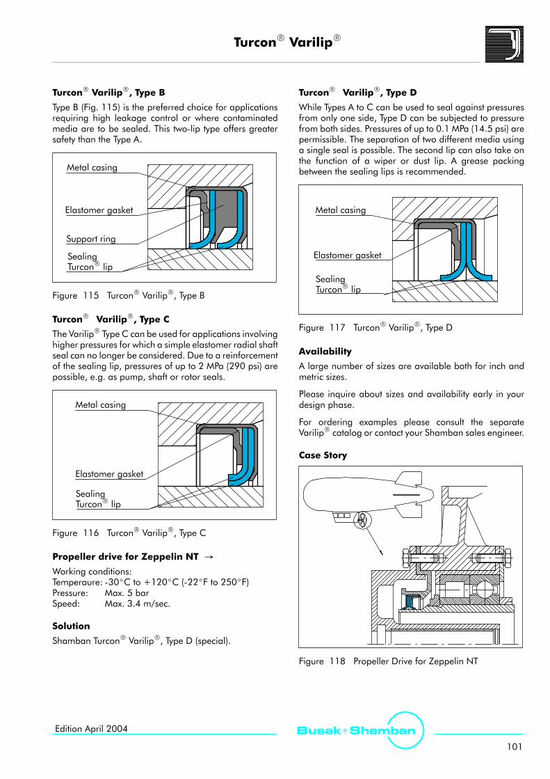
TurconR VarilipR
101
Busak+ ShambanEdition April 2004
TurconR VarilipR, Type B
Type B (Fig. 115) is the preferred choice for applicationsrequiring high leakage control or where contaminatedmedia are to be sealed. This two-lip type offers greatersafety than the Type A.
Metal casing
Elastomer gasket
Support ring
SealingTurconR lip
Figure 115 TurconR VarilipR, Type B
TurconR VarilipR, Type C
The VarilipR Type C can be used for applications involvinghigher pressures for which a simple elastomer radial shaftseal can no longer be considered. Due to a reinforcementof the sealing lip, pressures of up to 2 MPa (290 psi) arepossible, e.g. as pump, shaft or rotor seals.
Metal casing
Elastomer gasket
SealingTurconR lip
Figure 116 TurconR VarilipR, Type C
Propeller drive for Zeppelin NT →
Working conditions:Temperaure: -30_C to +120_C (-22_F to 250_F)Pressure: Max. 5 barSpeed: Max. 3.4 m/sec.
Solution
Shamban TurconR VarilipR, Type D (special).
TurconR VarilipR, Type D
While Types A to C can be used to seal against pressuresfrom only one side, Type D can be subjected to pressurefrom both sides. Pressures of up to 0.1 MPa (14.5 psi) arepermissible. The separation of two different media usinga single seal is possible. The second lip can also take onthe function of a wiper or dust lip. A grease packingbetween the sealing lips is recommended.
Metal casing
Elastomer gasket
SealingTurconR lip
Figure 117 TurconR VarilipR, Type D
Availability
A large number of sizes are available both for inch andmetric sizes.
Please inquire about sizes and availability early in yourdesign phase.
For ordering examples please consult the separateVarilipR catalog or contact your Shamban sales engineer.
Case Story
Figure 118 Propeller Drive for Zeppelin NT

Aerospace Engineering Guide
102
Busak+ Shamban Edition April 2004
Seals for Boeing Gland Standard BACS11AA
Description
The Boeing Footseal gland/seal specification BACS11AAwas intended for use in hydraulic systems to providemaximum O-Ring life with minimum friction.
Standard two back-up groovewidth per MIL-G-5514F at outeredge of groove only
Clearance0.13 mm max.(.005 inch)
Rod
29.5_ - 30.0_
Per MIL-G-5514F
Figure 119 Groove Geometry
Application Example
TurconR
Footseal IITurconR
ExcluderRDC
P
Figure 120 B777 Flight Controls
Alternative Seal Designs
The following Shamban seals are available in modifiedform to fit the BACS11AA gland:
Footseal II Part no. RF21 (S33121)Plus SealRII Part no. RP47 (S38647)WedgpakR Part no. RA49 (S38649)HatsealRII Part no. RH53 (S34853) *)
*) Only from 100 Series and up.
TurconR
Plus SealRIIRP47
TurconR
WedgpakRRA49
TurconR
HatsealRIIRH53
TurconR
Footseal IIRF21
Figure 121 Alternative Seal Design
The alternative designs should only be used afterconsulting your Shamban sales engineer.

Footseal II
103
Busak+ ShambanEdition April 2004
Footseal II *)
Description
The Footseal II rod seal was developed as animprovement to the original Footseal designed to fit theexisting Boeing BACS11AA rod gland standard.
pFootseal II
Figure 122 Footseal II
Method of Operation
Similar to other slipper seal designs, the Footseal II utilizesan O-Ring to preload the seal ring.
When the system pressure is increased, the oil film underthe seal is further reduced. Improvements in the FootsealII result in increased low pressure leakage performanceand longer life when compared to the standard Footseal.
The Footseal II also utilizes circumferential grooves toimprove leakage performance and provide longer lifesealing.
Advantages
- Good static sealing effect- Low friction- Fits BACS11AA gland standard
Technical Data
Operating pressure: 21 MPa (3000 psi)
Speed: 15.0 m/s (49.2 ft/s)
Temperature range: -54°C to +200°C(-65°F to +390°F)(depending on elastomer material)
Clearance: As per BACS11AA gland design
Media: Phosphate Ester,Mineral oil-based hydraulic fluids,Flame retardant hydraulic fluids,Environmentally safe hydraulic fluidsand others, depending on theelastomer material(see Table IV, page 16)
Materials
See Table I, page 12 and Table III, page 15.
Series
The Footseal II follows the series as described in BACS11AA.
Ordering Example
Footseal II for BACS11AA gland, standard series,Series No. RF21
Dash No.: 214
Material: T99
Order No. RF21 214 A T99
Series No.
BACS11AA size
Seal part includesCertificate of conformance (C.C.)
TurconR material code
0
Groove Standard (Boeing)
Standard
B
Note: O-Ring must be ordered seperately.
*) Shamban is the only authorized manufacturer of the Footseal II

TurconR ExcluderR and Scraper
104
Busak+ Shamban Edition April 2004
Selection of the Scraper Element
Scraper is a general term applied to those configurationsinstalled in hydraulic cylinders for the purpose of scrapingcontamination from rods, or excluding contaminationfrom the hydraulic system. The term scraper is generallyused in reference to those geometries that, although theyprovide a scraping function, do not prevent ingression ofsmall particles into the system. Excluders, in addition toproviding a scraping function, also minimize theingression of small particles into the system, and act as asecondary seal.
It is important to consider the scraper selection as anelement of a sealing system. Despite the proper selectionof primary and secondary seals, if a scraper appropriatefor the application is not selected, the resulting migrationof contamination into a system can cause damage to wearrings, seals, and hardware components. Scrapers thusform part of a functional system, and therefore must beviewed in combination with seals.
In order to satisfy a variety of technical and economicdemands, Shamban has developed a complete range ofscrapers with optimized geometries made fromhigh-quality materials.
An axial notch can be added to the inner scraping lip ofa double-acting scraper thereby providing a path to ventany interstage pressure to the outside while still retainingthe double-acting scraping effect. (See Fig. 128)
For systems with extreme working conditions, a springenergized scraper like the VarisealRM2S ensures a widetemperature range and optimal chemical resistance.
The final choice of scraper type and material must alsotake account of the detailed information on the individualscraper type elements.
Please do not hesitate to contact your sales engineer forfurther information on specific applications and specialtechnical questions.
Note on Ordering
All multi-element standard seals in this catalog whichcontain a proprietary elastomer part such as the Plus SealR
are always supplied as complete seal sets. The supplyincludes the seal and matching elastomer energizingelement.
O-Ring activated seals and scrapers are normallysupplied without the elastomer in order to increase theflexibility of delivery and stocking.
Exceptions to the above may be determined with yourlocal Shamban sales engineer to find the most suitablesolution.
Older designs no longer contained in this catalognaturally continue to be available. For all new applicationswe recommend the use of the types and preferred sizeslisted in this catalog.
Other combinations of TurconR materials and specialdesigns can be developed and supplied for specialapplications in intermediate sizes up to 3000 mm (10 ft)diameter, provided there is sufficient demand. Sizes over3000 mm (10 ft) are available for specific designs.
Groove Distance
When installing scrapers in conjunction with rod sealswhere interstage pressure is a concern, we recommendthe following positioning:
- Distance between seal groove and scraper groove Lshould exceed groove depth x
- Oil reservoir to collect the oil to be returned as shownin Figure 123.
ca. 3 mmL
x
øBøB+1.5 mm
Figure 123 Recommendations for Groove Distance

TurconR ExcluderR and Scraper
105
Busak+ ShambanEdition April 2004
TurconR DC Scraper Ring
Description
The TurconR DC Scraper Ring replaces the old S11065Series designed for the MS33675 military gland standard.This design utilizes a dual scraping lip TurconR elementwhich is scarf cut and energized by a garter spring.
Garter Spring
TurconR Ring
Figure 124 TurconR DC-Scraper Ring
Method of Operation
This design provides a good scraping effect and alsooffers a much more improved stability under linearactuation than the old S11065 design. Two possible pathsfor the ingression of contamination exist with this design:Through the scarf cut in the TurconR scraping element,and through the garter spring. This design should not beused in environments where severe contamination exists.
Advantages- Fits the MS33675 groove + BACS34A- Low friction- Easy installation- Can be installed in closed grooves- Two scraping lips- Good stability in the groove- Excellent chemical resistance due to the stainless steelspring activation
Technical Data
Speed: 15 m/s (49.2 ft/s)Temperature range:-200°C to +200°C
(-328°F to +390°F)Media: Practically all fluids, chemicals and
gases
Materials
TurconR T05 is standard. For other materials please seeTable I, page 12.
Series
The sizes in Table XLVIII, Installation Dimensions, page109 are the recommended standard sizes. Please consultyour Shamban sales engineer.
Ordering Example
DC Scraper, standard series,Series No. WM82
MS33675 Dash No: 012CorrespondingMIL-G-5514F Dash No: 217
Material: T05 (standard), see Table I, Page 12
Seal part includesCertificate of conformance (C.C.)
Order No. WM82 T05A
0 = No notch (standard)
Series No.
TurconR material code
012S
Dash No. (MS33675)
0
Groove Standard
Ordering Example
TurconR ExcluderRDC, Series E, standard series, withoutaxial notch, Series No. WE65, see page 106.
MS33675 Dash No: 017CorrespondingMIL-G-5514F Dash No: 325
Material: T05 (standard), see Table I, Page 12
Seal part includesCertificate of conformance (C.C.)
Order No. WE65 T05A
0 = No notch (standard)
Series No.
TurconR material code
017S
Dash No.(MS33675)
0
Groove Standard
Note: O-Ring must be ordered seperately. Sizes can befound in Table XLVIII, page 109.

TurconR ExcluderR and Scraper
106
Busak+ Shamban Edition April 2004
TurconR ExcluderRDC, Series E
Description
The TurconR ExcluderRDC, Series E consists of an uncut,dual scraping lip TurconR element energized by astandard O-Ring. This design is offered as a retrofit to theMS33675 military gland standard which previouslyutilized a cut, spring energized scraper design.
TurconR ExcluderR
Figure 125 TurconR ExcluderRDC, Series E
Method of Operation
This design addresses the two contamination pathsinherent in the DC Scraper Ring design. The scarf cut iseliminated, and the garter spring is replaced with anO-Ring. In effect, these two changes create a secondarysealing element. The outboard scraping lip minimizes theingression of water and contaminates, and equallyimportant, the inboard scraping lip will contain any fluidleakage that may pass the primary seal. This fluid willprovide lubrication for the sealing system, reducingfriction and extending the life of the sealing system.
Note, for diameters smaller than 25 mm (1 inch) a splitgroove is recommended.
Shamban offers other ExcluderR designs that have betterperformance under the above mentioned conditions. Forbest performance results, the MS33675 gland standardis not recommended. Also see the section ExcluderRDC,page 107.
Please contact your Shamban sales engineer for furtherinformation.
Advantages
- Fits the MS33675 groove- Acts as a secondary seal- Two scraping lips- Good stability in the groove
Scale 3:1Dash 1/4 - 7/16, 1 - 5
Dash 6 -13
Dash 14 - 25
Dash 26 - 36
Dash 37 - 49
Dash 50 - 67 Dash 68 - 71
Figure 126 Relationship Between the Profile Cross-Sections
Technical Data
Speed: 15 m/s
Temperature range: -54°C to +200°C(-65°F to +390°F)(depending on O-Ring material)
Media: Mineral oil-based hydraulic fluids,flame retardant hydraulic fluids,environmentally safe hydraulic fluids(bio-oils), Phosphate Ester, water andothers, depending on the O-Ringmaterial (see Tab. IV, page 16)
Materials
TurconR T05 is standard. For other materials please seeTable I, page 12.
Series
The sizes in Table XLVIII, Installation Dimensions, page109 are the recommended standard sizes. Larger andsmaller cross-sections are also available, please consultyour Shamban sales engineer.

TurconR ExcluderR and Scraper
107
Busak+ ShambanEdition April 2004
TurconR ExcluderRDC
Description
The design of the TurconR ExcluderRDC optimizes thedevice’s ability to exclude contamination without therestrictions and limitations of the MS33675 glanddimensions. The gland has been altered to accommodatea larger cross section O-Ring for better activation of thescraping lips.
TurconR ExcluderR
Figure 127 TurconR ExcluderRDC
Method of Operation
The wider groove, combined with a better support on thedownstream side of the ExcluderRDC, has resulted in a farmore reliable exclusion device than those utilizing theMS33675 gland standard. These changes have led towidespread acceptance of the ExcluderRDC as thestate-of-the-art exclusion device for aerospace applications.
Due to the heavy cross-section of the TurconR element onthe downstream side, the ExcluderRDC will accept asignificant back-pressure without being extruded out ofthe groove. If high back-pressure is expected, werecommend use of the ExcluderRDC with the axial notch.
Axial notch
Figure 128 Axial Notch (see page 105)
Open/split grooves are recommended for diameterssmaller than 35 mm (1.4 in).
Advantages
- Very efficient scraping lips- Capable of scraping light ice covering rods- Very stable and reliable design- Acts as a secondary seal.
Technical Data
Speed: 15 m/s (49 ft/s)
Temperature range: -54°C to +260°C(-65°F to +500°F)(depending on O-Ring material)
Media: Mineral oil-based hydraulic fluids,flame retardant hydraulic fluids,environmentally safe hydraulic fluids(bio-oils), Phosphate Ester, water andothers, depending on the O-Ringmaterial (see Table IV, page 16)
Materials
TurconR T05 is standard. For other materials, please seeTable I, page 12.
Design and Installation Recommendations
Scrapers and excluders can be installed either in split or inclosed grooves, depending upon cross-section and roddiameter. See below for our recommendations:
Table XLVII Installation in Closed Grooves
MS33675 Size P/N Rod
1/4 B100
5/16 B200 open grooves3/8 B300
open groovesrecommended
7/16 B400
001 -∞ B001 closed groovespossible
Ordering Example
TurconR ExcluderRDC for MS33675, rod
Dash size.: 5/16
Part No.: WE250B200AT05NG

TurconR ExcluderR and Scraper
108
Busak+ Shamban Edition April 2004
Series
The sizes in Table XLVIII, Installation Dimensions, page109 are the recommended standard sizes. Larger andsmaller cross sections are also available. Please consultyour Shamban sales engineer. Please note that theExcluderR size follows the dash numbering system as perMS33675 andmust be ordered with this dashNo. and notthe MIL-G-5514F/AS4716 dash No.
Dash 1/4 - 7/16
Dash 1 - 25
Dash 26 - 71
Scale 3:1
Figure 129 Relationship Between the Profile Cross-Sections
Ordering Example
TurconR ExcluderRDC, standard series, without axial notch,Series No. WE25
MS33675 Dash No: 005CorrespondingMIL-G-5514F Dash No: 210
Material: T05 (standard), see Table I, Page 12
Seal part includes Certificate ofconformance (C.C.)
Order No. WE25 T05A
0 = No Notch (standard)N = Notch
Series No.
TurconR material code
005B
Dash No. (MS33675)
0
Groove Standard
Ordering Example
TurconR ExcluderRDC, standard series, with axial notchSeries No. WE25 from Table XLVIII, page 109
MS 33675 Dash No: 005CorrespondingMIL-G-5514F Dash No: 210
Material: T05 (standard), see Table I, Page 12
Seal part includesCertificate of conformance (C.C.)
Order No. WE25 T05A
0 = No Notch (standard)N = Notch
Series No.
TurconR material code
005B
Dash No. (MS33675)
N
Groove Standard
DC Excluder, light series w, smaller cross section isavailable. Consult Your Shamban Sales Engineer.
Notes:
TurconR T05 is the standard material for theExcluderRDC due to its flexible properties. Othermaterials may be chosen. For example TurconR T42 ispreferred to scrape sticky deposits off the rod.
For the WE25 series, both an over- and under-sizeExcluderRDC is available for hard and light workingconditions. Please contact your Shamban salesengineer for details.
Please note that O-Rings must be orderedseparately ! Sizes can be found in Table XLVIII, page 109.Without the O-Ring the ExcluderRDC has unlimitedshelf life.
ExcluderR to fit larger and smaller grooves thanmentioned in Table XLVIII are available upon request.

TurconR ExcluderR and Scraper
109
Busak+ ShambanEdition April 2004
Installation TurconR ExcluderRDC, Series No. WE25 (Old Series No. S32925),TurconR ExcluderRDC, Series E, Series No. WE65 (Old Series No S33865) andTurconR DC Scraper, Series No. WM82 (Old Series No. S34382)
G1 0.4 mm0.015 inch
45_
min.G2
øDøA2
øB
(WE25_B) (WE65_S)øA1
øB
F/2
Figure 130 Installation DrawingTable XLVIII Groove DimensionsRod Size Rod Dia. øB Shamban Size WE25 MS33675, WE65 and WM82
MS-3367
Inch mm Groove Dia.
øA1
Width
G1
Dia.Cl.F
(max)
O-Ringsize
AS568A
Groove Dia.
øA2
Dia.Clearance
øD
Width
G2
O-RingsizeonlyWE65
675
Inch mm Inch/
mm
Inch/
mm
568AInch mm Inch mm Inch
/mm
WE65
AS568A
+0.000-0.001
+0.00-0.03
+0.002-0.000
+0.05-0.00
144
+0.004-0.000
+0.10-0.00
+0.005-0.000
+0.13-0.00
1/45/163/87/16
0.2480.3100.3730.435
6.307.879.4711.05
0.4360.4980.5610.623
11.0712.6514.2515.82
.144+.005/-0
|3.66
+0.13/-0
011012013014
0.5100.5720.6360.697
12.9514.5316.1517.70
0.3980.4600.5230.585
10.1111.6813.2814.86
012013014015
+0.000-0.002
+0.00-0.05
001002003004
0.4980.5600.6230.685
12.6514.2215.8217.40
0.7660.8280.8910.953
19.4621.0322.6324.21
113114115116
0.7600.8230.8850.948
19.3020.9022.4824.08
0.6470.7100.7720.834
16.4318.0319.6121.18
016017018019
005006007008009
010011012013014
015016
0.7480.8100.8730.9350.998
1.0601.1231.1851.2481.310
1.3731.435
19.0020.5722.1723.7525.35
26.9228.5230.1031.7033.27
34.8736.45
1.0161.0781.1411.2031.266
1.3281.3911.4531.5161.578
1.6411.703
25.8127.3828.9830.5632.16
33.7335.3336.9138.5140.08
41.6843.26
.195+.005/-0
|4.95
+0.13/-0
.042|
1.07
117118119120121
122123124125126
127128
1.0101.0861.1481.2101.273
1.3351.3981.4601.5231.614
1.6771.739
25.6527.5829.1630.7332.33
33.9135.5137.0838.6841.00
42.6044.17
0.8970.9491.0121.0741.136
1.1991.2621.3241.3861.480
1.5421.605
22.7824.1025.7027.2828.85
30.4532.0533.6335.2037.59
39.1740.77
.104+.005/-0
|2.64
+0.13/-0
020021022023024
025026027028029
029030
017018019
1.4981.6231.748
38.0541.2244.40
1.7661.8912.016
44.8648.0351.21
129131133
1.8021.9272.052
45.7748.9552.12
1.6681.7931.918
42.3745.5448.72
030031032
Metric sizes.

TurconR ExcluderR and Scraper
110
Busak+ Shamban Edition April 2004
Rod Size Rod Dia. øB Shamban Size WE25 MS33675, WE65 and WM82
MS3367
Inch mm Groove Dia.
øA1
Width
G1
Dia.Cl., F(max)
O-Ringsize
AS
Groove Dia.
øA2
Dia.Clearance
øD
Width
G2
O-RingsizeonlyWE65
675
Inch mm Inch/
mm
Inch/
mm
AS568A Inch mm Inch mm Inch
/mm
yWE65
AS568A
+0.000-0.002
+0.00-0.05
+0.002-0.000
+0.05-0.00
+0.004-0.000
+0.10-0.00
+0.005-0.000
+0.13-0.00
020021022023024025
1.8731.9982.1232.2482.3732.498
47.5750.7553.9257.1060.2763.45
2.1412.2662.3912.5162.6412.766
54.3857.5660.7363.9167.0870.26
.195+.005/-0
|4.95
+0.13/-0
135137139141143145
2.1772.3022.4272.5522.6772.802
55.3058.4761.6564.8268.0071.17
2.0432.1782.3032.4282.5532.678
51.8955.3258.5061.6764.8568.02
.104+.005/-0
|2.64
+0.13/-0
033034035036037038
026027028029030
031032033034035036
2.6232.7482.8732.9973.122
3.2473.3723.4973.6223.7473.872
66.6269.8072.9776.1279.30
82.4785.6588.8292.0095.1798.35
2.9713.0963.2213.3453.470
3.5953.7203.8453.9704.0954.220
75.4678.6481.8184.9688.14
91.3194.4997.66100.84104.01107.19
232233234235236
237238239240241242
2.9893.1143.2393.3643.489
3.6143.7393.8643.9894.1144.239
75.9279.1082.2785.4588.62
91.8094.9798.15101.32104.50107.67
2.8342.9593.0843.2093.334
3.4593.5843.7093.8343.9594.084
71.9875.1678.3381.5184.68
87.8691.0394.2197.38100.56103.73
.119+.005/-0
|3.02
+0.13/-0
039040041041042
042043043044044045
037038039040
3.9974.1224.2474.372
101.52104.70107.87111.05
4.3454.4704.5954.720
110.36113.54116.71119.89
243244245246
4.4274.5524.6774.802
112.45115.62118.80121.97
4.2404.3654.4904.615
107.70110.87114.05117.22
156156157157
+0.000-0.003
+0.00-0.08
+0.003-0.000
+0.08-0.00
+0.005-0.000
+0.13-0.00
041042043044045
046047048049
4.4974.6224.7474.8724.997
5.1225.2475.3725.497
114.22117.40120.57123.75126.92
130.10133.27136.45139.62
4.8454.9705.0955.2205.345
5.4705.5955.7205.845
123.06126.24129.41132.59135.76
138.94142.11145.29148.46
.240+.005/-0
|6.10
+0.13/-0
.042|
1.07
247248249250251
252253254255
4.9275.0525.1775.3025.427
5.5525.6775.8025.927
125.15128.32131.50134.67137.85
141.02144.20147.37150.55
4.7404.8654.9905.1155.240
5.3655.4905.6155.740
120.40123.57126.75129.92133.10
136.27139.45142.62145.80
.135+.005/-0
|3.43
+0.13/-0
158158159159160
160161161162
050051052053054
055056057058059
5.6225.7475.8725.9976.247
6.4976.7476.9977.2477.497
142.80145.97149.15152.32158.67
165.02171.37177.72184.07190.42
5.9706.0956.2206.3456.595
6.8457.0957.3457.5957.845
151.64154.81157.99161.16167.51
173.86180.21186.56192.91199.26
256257258258259
260261262263264
6.1146.2396.3646.4896.739
6.9897.2397.4897.7397.989
155.30158.47161.65164.82171.17
177.52183.87190.22196.57202.92
5.8966.0226.1466.2726.522
6.7727.0227.2727.5227.772
149.76152.96156.11159.31165.66
172.01178.36184.71191.82197.41
.151+.005/-0
|3.84
162163163164165
166167168169170
060 7.747 196.77 8.095 205.61 265 8.239 209.27 8.022 203.763.84
+0.13/-0 171+0.005-0.000
+0.13-0.00
061062063064065
066067
7.9978.4978.9979.4979.997
10.49710.997
203.12215.82228.52241.22253.92
266.62279.32
8.3458.8459.3459.84510.345
10.84511.345
211.96224.66237.36250.06262.76
275.46288.16
266268270272274
275276
8.4898.9899.4899.98910.489
10.98911.489
215.62228.32241.02253.72266.42
279.12291.82
8.2728.7729.2729.77210.272
10.77211.272
210.11222.81235.51248.21260.91
273.61286.31
172174176178
068069070071
11.49711.99712.49712.997
292.02304.72317.42330.12
11.84512.34512.84513.345
300.86313.56326.26338.96
277278278279
11.98912.48912.98913.489
304.52317.22329.92342.62
11.77212.27212.77213.272
299.01311.71324.41337.11
.166+.005/-0
|4.22
+0.13/-0
278278279279
Metric sizes.

TurconR VarisealRM2S
111
Busak+ ShambanEdition April 2004
TurconR VarisealRM2S Scraper
Description
The TurconR VarisealRM2S is a single-acting seal/scraperconsisting of a U-shaped seal jacket and a V-shapedcorrosion resistant spring.
The most unique characteristic of the VarisealRM2S is thenewly developed asymmetric seal profile, where thedynamic lip has an optimized heavy profile, and offerslong service life and a good scraping effect, even in highlyviscous media.
TurconR Ring
V-shaped spring
Figure 131 TurconR VarisealRM2S
The VarisealRM2S can be sterilized and is available in aspecial Hi-Clean version where the spring cavity is filledwith silicone to prevent contaminants from beingentrapped in the seal. This design also works well inapplications involving mud, slurries, ice, and prevents gritfrom packing into the seal cavity and inhibiting the springaction.
VarisealRM2S can be installed in grooves to MIL-G-5514F/AS4716 and ISO 3771. The seal can only be installed toa limited extent in closed grooves. Installation instructions,see page 75. Utilize Table XXIX and Table XXXI.
Advantages
- Excellent scraping effect
- Reciprocating and turning movement
- Low friction characteristics for precise control
- High abrasion resistance and dimensional stability
- Can handle rapid changes in temperature
- Suitable for use in a variety of caustic media
- Can be sterilized
- Unlimited shelf life.
Technical Data
Speed: Reciprocating up to 15 m/s (49.8 ft.)Turning up to 0.5 m/s (1.65 ft/s)
Temperature: -70°C to +260°C(-94°F to +500°F)
For specific applications at lowertemperatures, please ask yourShamban sales engineer
Media: Typically fluids with medium to highviscocity and media containinghard particles
Materials
For spring and material selection, see Table XXIV, page 70.

TurconR VarisealRM2S
112
Busak+ Shamban Edition April 2004
Installation VarisealRM2S Scraper, Series No. RVC, Rod
L1
r1X
D/2
L1
r1
D/2
RVC
Stepped groove Split grooveøA
øB
øA
øB
Figure 132 Installation Drawing
Table XLIX Groove Dimensions (metric)
SeriesNo.
Rod DiameterøB h9
GrooveDiameter
GrooveWidth
Radius Step2)
HeightRadial Clearance
D/2 max.*
RecommendedRange
Extended1)Range øA H9 L1 +0.2 r1 X
<2 MPa(300 psi)
<10 MPa(1500 psi)
<21 MPa(3000 psi)
<40 MPa(5800 psi)
RVC0 3.0 - 9.9 3.0 - 40.03) øB + 2.9 2.4 0.4 0.4 0.20 0.10 0.08 0.05
RVC1 10.0 - 19.9 6.0 - 200.03) øB + 4.5 3.6 0.4 0.6 0.25 0.15 0.10 0.07
RVC2 20.0 - 39.9 10.0 - 400.03) øB + 6.2 4.8 0.6 0.7 0.35 0.20 0.15 0.08
RVC3 40.0 - 119.9 20.0 - 700.03) øB + 9.4 7.1 0.8 0.8 0.50 0.25 0.20 0.10
RVC4 120.0 - 999.9 35.0 - 999.93) øB + 12.2 9.5 0.8 0.9 0.60 0.30 0.25 0.12
* At pressures > 40 MPa: D/2 max. use H8/f81) Available on request2) Maximum X = 0.02 x øB
3) For diameters larger than ”Recommended Range”: the tolerance on øAis changed from H9 to H8. For pressure above 40 MPa (5000 psi),please contact your Shamban sales engineer.
Ordering ExampleTurconR VarisealRM2S, Series RVC3.Rod diameter: øB = 80.0 mmPart No: RVC300800
Select the materials from Table I, page 12 and Table XXIV,page 70. The corresponding code numbers areappended to the Part No. Together these form the ordernumber.The order number for all intermediate sizes not shown inTable XLIX can be determined by following the exampleopposite.
0800 T40 SRVC3
TurconR material code
Series No.
Order No.
Material Code - spring
Rod diameter x 10Seal part includesCertificate of conformance (C.C.)
D
Hi-Clean - option
A
Standard
0

TurconR VarisealRM2S
113
Busak+ ShambanEdition April 2004
Installation VarisealRM2S Scraper, Series No. PVC, Bore
L1 r1
Y
D/2
L1r1
PVC
Stepped groove Split groove
D/2
øA
øB
øA
øB
Figure 133 Installation Drawing
Table L Groove Dimensions (metric)
SeriesNo.
Bore DiameterøA H9
GrooveDiameter
GrooveWidth Radius Step2)
HeightRadial Clearance
D/2 max*
RecommendedRange
Extended1)
Range øB h9 L1 +0.2 r1 Y<2 MPa(300 psi)
<10 MPa(1500 psi)
<21 MPa(3000 psi)
<40 MPa(5800 psi)
PVC0 6.0 - 13.9 6.0 - 40.03) øA-2.9 2.4 0.4 0.4 0.20 0.10 0.08 0.05
PVC1 14.0 - 24.9 10.0 - 200.03) øA-4.5 3.6 0.4 0.6 0.25 0.15 0.10 0.07
PVC2 25.0 - 45.9 16.0 - 400.03) øA-6.2 4.8 0.6 0.7 0.35 0.20 0.15 0.08
PVC3 46.0 - 124.9 28.0 - 700.03) øA-9.4 7.1 0.8 0.8 0.50 0.25 0.20 0.10
PVC4 125.0 - 999.9 45.0 - 999.93) øA-12.2 9.5 0.8 0.9 0.60 0.30 0.25 0.12
*At pressures > 40 MPa D/2max use H8/f81) Available on request.2) Maximum Y = 0.035 x øA
3) For diameters larger than ”Recommended Range”: the tolerance onøB is changed fromh9 to h8. For pressure above 40MPa (5000 PSI),please contact your Shamban sales engineer.
Ordering exampleTurconR VarisealRM2S, Series PVC3.Bore diameter: øA = 80.0 mmPart No.: PVC300800
Select the materials from Table I, page 12 and Table XXIV,page 70. The corresponding code numbers areappended to the Part No. Together these form the ordernumber.For all intermediate sizes not shown in Table L, the OrderNo. can be determined from the example shown opposite.
0800 T40 SPVC3
TurconR material code
Series No.
Order No.
Material Code - spring
Bore diameter x 10Seal part includesCertificate of conformance (C.C.)
D
Hi-Clean - option
A
Standard
0

TurciteR SlydringR / LuytexR SlydringR
114
Busak+ Shamban Edition April 2004
TurciteR SlydringR / LuytexR SlydringR
The purpose of the rings is to guide the piston and rod ofa working cylinder and to absorb the transverse forceswhich may occur. Metallic contact between the slidingparts of the cylinder must be prevented. Non-metallicSlydringR offer major benefits compared with thetraditional metallic bearings:
- Cost efficient.
- High load bearing capacity.
- Eliminates local stress concentrations.
- Very wear-resistant, long service life.
- Eliminates galling.
- Good friction characteristics.
- Damping of mechanical vibrations.
- Protection of the seal against ”dieseling”.
- Eliminates hydrodynamic problems in the guide system.
- Easy installation.
- Low maintenance costs.
Designs
Three different types of SlydringR materials are availabledepending upon application demands:
- Highly wear-resistant, low friction, specially modifiedTurciteRmaterials for low to medium loads - SlydringR.
- LuytexR fabric composite materials for high loads andtransverse forces - SlydringR.
- ZurconR. High modulus thermoplastics for high loads,temperature with long service life.
SlydringR for Aerospace Applications
In the past, due to the imposed limitations ofMIL-G-5514F/AS4716 and the minimum requiredclearance gaps necessary to minimize seal extrusion,SlydringR use has been limited. The use of SlydringR oftenrequires larger clearance gaps.
With the trend toward higher hydraulic system pressures,resulting in higher sideloads, the use of SlydringR becomesnecessary in order to protect primary seals and hardware.
Since no industry standard has been developed forSlydringR, we have a wide range of sizes available inpreformed rings.
SlydringR are provided as cut rings with an angle cut asstandard. For special applications, other cut types areavailable; consult your Shamban sales engineer.
Table LI Selection Criteria for TurciteR SlydringR / LuytexR SlydringR
Material Filler Technical Data Application
MaterialD i i
Temperature Velocitya e aDesignation
e pe a u e e oc y
C_/F_ m/s(ft/s)
TurconR T08 High filled bronze
TurconR T10 2) Carbon / Graphite -80 to +200(-112 to +392)
15(99) Standard bearing for low to medium load
TurconR T29 Carbon fiber
( ) ( )
LuytexR C380 Polyesther resin + PTFE -60 to +130(-76 to +266)
1(3.3) High sideload 1)
ZurconR Z43High modulus thermoplasticand PTFE + Carbon
-80 to +200(-112 to +392)
15(99)
High speed, temperature and pressure.Excellent for PFC
1) Consult your Shamban sales engineer prior to applying LuytexR.2) TurconR T11, used in North America is equivalent to TurconR T10.

TurciteR SlydringR / LuytexR SlydringR
115
Busak+ ShambanEdition April 2004
Installation Recommendations, TurciteR SlydringR / LuytexR SlydringR for PistonSeries No. GP0 (Old Series No. S34545, S34546 and S34547)
W
G
D/2
R max.
øA
øF
Figure 134 Installation Drawing
Table LII Groove Dimensions
SeriesNo.
BoreDiameter
GrooveDiameter
GrooveWidth
RadialClearance
Inch mm Inch mm Inch mm Inch mm
øA øA øF h8 øF h8 G +0.010 G +0.25 D/2max. D/2max.
GP02X 0.235 - 1.491 5.97 - 37.87 øA - 0.064 øA - 1.63 0.135 3.43 0.007 0.18
GP04X 0.235 - 1.491 5.97 - 37.87 øA - 0.064 øA - 1.63 0.260 6.60 0.007 0.18
GP06X 0.235 - 1.491 5.97 - 37.87 øA - 0.064 øA - 1.63 0.385 9.78 0.007 0.18
GP08X 0.235 - 1.491 5.97 - 37.87 øA - 0.064 øA - 1.63 0.510 12.95 0.007 0.18
GP02W 0.550 - 4.468 13.97 - 113.49 øA - 0.126 øA - 3.20 0.135 3.43 0.009 0.23
GP04W 0.550 - 4.468 13.97 - 113.49 øA - 0.126 øA - 3.20 0.260 6.60 0.009 0.23
GP06W 0.550 - 4.468 13.97 - 113.49 øA - 0.126 øA - 3.20 0.385 9.78 0.009 0.23
GP08W 0.550 - 4.468 13.97 - 113.49 øA - 0.126 øA - 3.20 0.510 12.95 0.009 0.23
GP02Y 2.993 - 10.474 76.02 - 266.04 øA - 0.188 øA - 4.78 0.135 3.43 0.011 0.28
GP04Y 2.993 - 10.474 76.02 - 266.04 øA - 0.188 øA - 4.78 0.260 6.60 0.011 0.28
GP06Y 2.993 - 10.474 76.02 - 266.04 øA - 0.188 øA - 4.78 0.385 9.78 0.011 0.28
GP08Y 2.993 - 10.474 76.02 - 266.04 øA - 0.188 øA - 4.78 0.510 12.95 0.011 0.28
Metric sizes.
Table LIII Recommended Radius for Groove Dia.
Bore Diameter Rmax.
Inch mm Inch mm
< 9.842 < 250.0 0.008 0.2
> 9.842 > 250.0 0.015 0.4
Metric sizes.
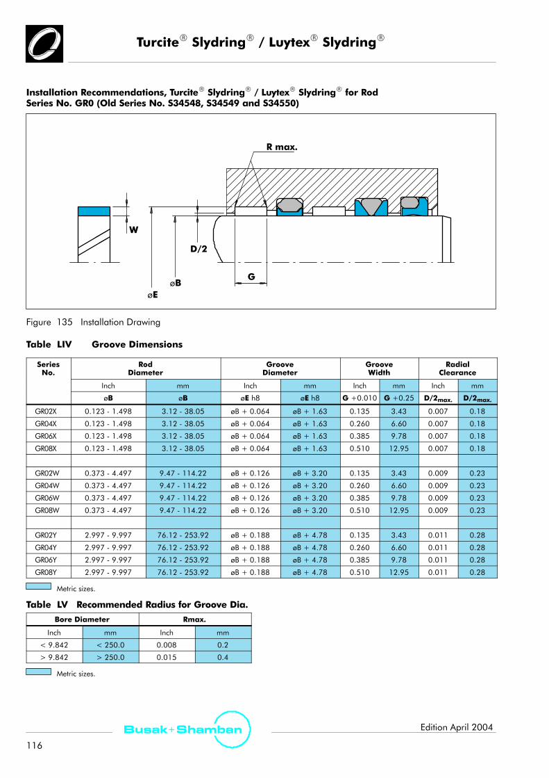
TurciteR SlydringR / LuytexR SlydringR
116
Busak+ Shamban Edition April 2004
Installation Recommendations, TurciteR SlydringR / LuytexR SlydringR for RodSeries No. GR0 (Old Series No. S34548, S34549 and S34550)
R max.
W
D/2
G
øEøB
Figure 135 Installation Drawing
Table LIV Groove Dimensions
SeriesNo.
RodDiameter
GrooveDiameter
GrooveWidth
RadialClearance
Inch mm Inch mm Inch mm Inch mm
øB øB øE h8 øE h8 G +0.010 G +0.25 D/2max. D/2max.
GR02X 0.123 - 1.498 3.12 - 38.05 øB + 0.064 øB + 1.63 0.135 3.43 0.007 0.18
GR04X 0.123 - 1.498 3.12 - 38.05 øB + 0.064 øB + 1.63 0.260 6.60 0.007 0.18
GR06X 0.123 - 1.498 3.12 - 38.05 øB + 0.064 øB + 1.63 0.385 9.78 0.007 0.18
GR08X 0.123 - 1.498 3.12 - 38.05 øB + 0.064 øB + 1.63 0.510 12.95 0.007 0.18
GR02W 0.373 - 4.497 9.47 - 114.22 øB + 0.126 øB + 3.20 0.135 3.43 0.009 0.23
GR04W 0.373 - 4.497 9.47 - 114.22 øB + 0.126 øB + 3.20 0.260 6.60 0.009 0.23
GR06W 0.373 - 4.497 9.47 - 114.22 øB + 0.126 øB + 3.20 0.385 9.78 0.009 0.23
GR08W 0.373 - 4.497 9.47 - 114.22 øB + 0.126 øB + 3.20 0.510 12.95 0.009 0.23
GR02Y 2.997 - 9.997 76.12 - 253.92 øB + 0.188 øB + 4.78 0.135 3.43 0.011 0.28
GR04Y 2.997 - 9.997 76.12 - 253.92 øB + 0.188 øB + 4.78 0.260 6.60 0.011 0.28
GR06Y 2.997 - 9.997 76.12 - 253.92 øB + 0.188 øB + 4.78 0.385 9.78 0.011 0.28
GR08Y 2.997 - 9.997 76.12 - 253.92 øB + 0.188 øB + 4.78 0.510 12.95 0.011 0.28
Metric sizes.
Table LV Recommended Radius for Groove Dia.
Bore Diameter Rmax.
Inch mm Inch mm
< 9.842 < 250.0 0.008 0.2
> 9.842 > 250.0 0.015 0.4
Metric sizes.

TurciteR SlydringR / LuytexR SlydringR
117
Busak+ ShambanEdition April 2004
Ordering example - Piston
SlydringR for bore diameter A: 91.90 mm (3.618 inch)Dash No. per MIL-G-5514F: -339Series GP0 from Table LII, page 115
Groove width: 9.78 mm (0.385 inch)Groove depth: 2.39 mm (0.094 inch)
Material: TurconR T10see Table I, page 12.
Order No. GP T10*AB339Y06
TurconR material code
Seal part includesCertificate of conformance (C.C.)
Dash No.
Groove Depth
Groove Width
Series No.
* TurconR T11, used in North America is equivalent toTurconR T10
Ordering example - Rod
SlydringR for rod diameter B: 38.05 mm (1.498 inch)Dash No. per MIL-G-5514F: -325Series GR0 from Table LIV, page 116
Groove width: 6.60 mm (0.260 inch)Groove depth: 1.60 mm (0.063 inch)
Material: TurconR T29see Table I, page 12
Order No. GR T29AB325W04
TurconR material code
Seal part includesCertificate of conformance (C.C.)
Dash No.
Groove Depth
Groove Width
Series No.
Note: SlydringR in material LuytexR and ZurconR willuse special Part No. due to tolerance and temperaturevariations. For other sizes, (width/depth) and special PartNo. consult your Shamban sales engineer.

TurconR WedgpakR Face Seal
118
Busak+ Shamban Edition April 2004
TurconR WedgpakR Face Seal
Description
The TurconRWedgpakR Face Seal is an adaptation of thetraditional WedgpakR design to maximize performancein face seal applications. It utilizes a triangular shapedTurconR delta ring energized by a uniquely shapedelastomer designed to maximize extrusion protectionunder abnormal clearance gap conditions.
TurconR delta ring
elastomer
p
Figure 136 TurconR WedgpakR Face Seal
Method of OperationIt is typical for face seal applications to experience impulsepressures and therefore abnormally high ”breathing”conditions in mating hardware. The TurconR delta ringuses the full depth of the seal groove to optimize theamount of material available and maximize extrusionprotection under worst case conditions. The specialshaped geometry of the elastomer provides a preloadunder low pressure conditions, and constantly forces theTurconR delta ring up against the clearance gap toprevent extrusion of the elastomer.
Advantages
- Excellent static sealing effect- Good extrusion protection- Easy installation
Technical Data
Operating pressure: 35 MPa (5000 psi)
Speed: Not applicable
Temperature range: -54°C to +200°C(-65°F to +390°F)(depending on elastomer material)
Clearance: Can exceed recommendations ofMIL-G-5514F/AS4716 dependentupon the combination of pressuresand clearance gaps
Media: Mineral oil-based hydraulic fluids,flame retardant hydraulic fluids,environmentally safe hydraulic fluids(bio-oils), Phosphate Ester, water andothers, depending on the elastomermaterial (see Table IV, page 16)
MaterialsSee Table I, page 12 and Table III, page 15.
SeriesThe WedgpakR Face Seal follows the series as described infollowing pages. Special sizes are available upon request.Please contact your Shamban sales engineer.
000 Series
100 Series
200 Series
300 Series
Scale 3:1
Figure 137 Relationship Between the Profile Cross-Section
Case Story
TurconR
WedgpakR Face Seal
Figure 138 Engine Driven Hydraulic Pump Flange SealRetrofit
Problem
Operators of wide bodied aircraft have experiencedleakage of engine driven pumps, between adaptor blockand housing.
Solution
TurconR WedgpakR Face Seal eliminated leakagefailures.

TurconR WedgpakR Face Seal
119
Busak+ ShambanEdition April 2004
Installation TurconR WedgpakR Face Seal, Series No. DW00 (Old Series No. S38000), Internal
øAG
R
L
Figure 139 Installation Drawing
Table LVI Groove Dimensions
D h
øADia.
GGroove Width.
LGroove Depth
R
DashNo Inch mm Inch mm Inch mm InchNo
+0.000-0.005
+0.00-0.13
+0.010-0.000
+0.25-0.00 ±0.001 ±0.03
Inch/
mm
008009010
011012013014015
016017018019020
021022023024025
026027028
0.3160.3480.379
0.4410.5040.5660.6290.691
0.7540.8160.8790.9411.004
1.0661.1291.1911.2541.316
1.3791.4411.504
8.038.949.63
11.2012.8014.3815.9817.55
19.1520.7322.3323.9025.50
27.0828.6830.2531.8533.43
35.0336.6038.20
0.094 2.39 0.057 1.45
0.005|
0.015
0.13|
0.38
110111112113114115
116117118119120
0.5680.6300.6930.7550.8180.880
0.9431.0051.0681.1301.193
14.4316.0017.6019.1820.7822.35
23.9525.5327.1328.7030.30
0.141 3.58 0.090 2.29
D h
øADia.
GGroove Width.
LGroove Depth
R
DashNo Inch mm Inch mm Inch mm InchNo
+0.000-0.005
+0.00-0.13
+0.010-0.000
+0.25-0.00 ±0.001 ±0.03
Inch/
mm
121122123124125
126127128129130
131132133134135
1.2551.3181.3801.4431.505
1.5681.6301.6931.7551.818
1.8801.9432.0052.0682.131
31.1233.4835.0536.6538.23
39.8341.4043.0044.5846.18
47.7549.3550.8352.5354.13
0.141 3.58 0.090 2.29
0.005|
0.015
0.13|
0.38
210211212213214215
216217218219220
221222223224225
226
1.0121.0741.1371.1991.2621.324
1.3871.4491.5121.5741.637
1.6991.7621.8872.0122.137
2.262
25.7027.2828.8830.4532.0533.63
35.2336.8038.4039.9841.58
43.1544.7547.9351.1054.28
57.45
0.188 4.78 0.122 3.10
0.010|
0.025
0.25|
0.63
Metric sizes.

TurconR WedgpakR Face Seal
120
Busak+ Shamban Edition April 2004
D h
øADia.
GGroove Width.
LGroove Depth R
DashNo Inch mm Inch mm Inch mm InchNo
+0.000-0.005
+0.00-0.13
+0.010-0.000
+0.25-0.00 ±0.001 ±0.03
Inch/
mm
227228229230
231232233234235
236237238239240
241242243244245
246247
2.3872.5122.6372.762
2.8873.0123.1373.2623.387
3.5123.6373.7623.8874.012
4.1374.2624.3874.5124.637
4.7624.887
60.6363.8066.9870.15
73.3376.5079.6882.8586.03
89.2089.8495.5598.73101.90
105.08108.25111.43114.60117.78
120.95124.13
0.188 4.76 0.122 3.10
0.010|
0.025
0.25|
0.63
325326327328329330
331332333334335
336337338339340
341342343344345
346347348349
1.8952.0202.1452.2702.3952.520
2.6452.7702.8953.0203.145
3.2703.3953.5203.6453.770
3.8954.0204.1454.2704.395
4.5204.6454.7704.895
48.1351.3154.4857.6660.8364.01
67.1870.3673.5376.7179.88
83.0686.2389.4192.5895.76
98.93102.11105.28108.46111.63
114.81117.98121.16124.33
0.281 7.14 0.187 4.75
0.020|
0.035
0.51|
0.89
Metric sizes.
Ordering Example
WedgpakR Face Seal for internal useSeries No. DW00
Dash No: 115
Material: T29 EH
Order No. DW00 115 A T29 EH
Series No.
Shamban gland specification
Seal part includesCertificate of conformance (C.C.)
TurconR material code
Elastomer material code
0
0 = Standard
Groove standard
B

TurconR WedgpakR Face Seal
121
Busak+ ShambanEdition April 2004
Installation TurconR WedgpakR Face Seal, Series No. DW01 (Old Series No. S38001), External
øB G
R
L
Figure 140 Installation Drawing
Table LVII Groove Dimensions
D h
øBDia.
GGroove Width.
LGroove Depth R
DashNo Inch mm Inch mm Inch mm InchNo
+0.000-0.005
+0.00-0.13
+0.010-0.000
+0.25-0.00 ±0.001 ±0.03
Inch/
mm
008009010
011012013014015
016017018019020
021022023024025
026027028
0.1760.2080.239
0.3010.3640.4260.4890.551
0.6140.6760.7390.8010.864
0.9260.9891.0511.1141.176
1.2391.3011.364
4.475.286.07
7.659.2510.8212.4214.00
15.6017.1718.7720.3521.95
23.5225.1226.7028.3029.87
31.4733.0534.65
0.094 2.39 0.057 1.45
0.005|
0.015
0.13|
0.38
110111112113114115
116117118119120
0.3620.4240.4870.5490.6120.674
0.7370.7990.8620.9240.987
9.1910.7712.3713.9415.5417.12
18.7220.2921.8923.4725.07
0.141 3.58 0.090 2.29
D h
øBDia.
GGroove Width.
LGroove Depth R
DashNo Inch mm Inch mm Inch mm InchNo
+0.000-0.005
+0.00-0.13
+0.010-0.000
+0.25-0.00 ±0.001 ±0.03
Inch/
mm
121122123124125
126127128129130
131132133134135
1.0491.1121.1741.2371.299
1.3621.4241.4871.5491.612
1.6741.7371.7991.8621.925
26.6428.2429.8231.4232.99
34.5936.1737.7739.3440.94
42.5244.1245.6947.2948.90
0.141 3.58 0.090 2.29
0.005|
0.015
0.13|
0.38
210211212213214215
216217218219220
221222223224225
226
0.7340.7960.8590.9210.9841.046
1.1091.1711.2341.2961.359
1.4211.4841.6091.7341.859
1.984
18.6420.2221.8223.3924.9926.57
28.1729.7431.3432.9234.52
36.0937.6940.8744.0447.22
50.39
0.188 4.76 0.122 3.10
0.010|
0.025
0.25|
0.63
Metric sizes.

TurconR WedgpakR Face Seal
122
Busak+ Shamban Edition April 2004
D h
øBDia.
GGroove Width.
LGroove Depth R
DashNo Inch mm Inch mm Inch mm InchNo
+0.000-0.005
+0.00-0.13
+0.010-0.000
+0.25-0.00 ±0.001 ±0.03
Inch/
mm
227228229230
231232233234235
236237238239240
241242243244245
246247
2.1092.2342.3592.484
2.6092.7342.8592.9843.109
3.2343.3593.4843.6093.734
3.8593.9844.1094.2344.359
4.4844.609
53.5756.7459.9263.09
66.2769.4472.6275.7978.97
82.1485.3288.4991.6794.84
98.02101.19104.37107.54110.72
113.89117.07
0.188 4.76 0.122 3.10
0.010|
0.025
0.25|
0.63
325326327328329330
331332333334335
336337338339340
341342343344345
346347348349
1.4751.6001.7251.8501.9752.100
2.2252.3502.4752.6002.725
2.8502.9753.1003.2253.350
3.4753.6003.7253.8503.975
4.1004.2254.3504.475
37.4740.6443.8246.9950.1753.34
56.5259.6962.8766.0469.22
72.3975.5778.7481.9285.09
88.2791.4494.6297.79100.97
104.14107.32110.49113.67
0.281 7.14 0.187 4.75
0.020|
0.035
0.51|
0.89
Metric sizes.
Ordering Example
WedgpakR Face Seal for external useSeries No. DW01
Dash No: 236
Material: T05 NG
Order No. DW01 236 A T05 NG
Series No.
Shamban gland specification
Seal part includesCertificate of conformance (C.C.)
TurconR material code
Elastomer material code
0
0 = Standard
Groove standard
B

Aerospace Engineering Guide
123
Busak+ ShambanEdition April 2004
Installation Instructions
General Comments
After choosing the right seal design, the second mostimportant issue is to install the seal without damaging it.
The following hardware characteristics should beconsidered at an early hardware design stage in order toensure damage free installation of seals.
Rod lead inchamfer
Seal groove radiusRounded to 0.3 mm max.
Bevelled ports Bore lead-in chamfer
Installationpath free fromnicks andburrs
Installation tool to cover thread etc.Preferably made of plastic
Figure 141 Methods of Hardware Design to Prevent Seal Damage
- The installation path should be kept free of nicks, burrs,scratches, or any sharp edge that could damage theseal.
- Any tool used to install seals should be free of sharpedges. Screwdrivers are especially notorious fordamaging sealing lips and should not be used tohandle the seals.
- Tools made out of hard plasticlike Delrin or Nylon arepreferred.
- In situations where heat is required to soften andexpand the TurconR-seal components, submerse themfor a few minutes in hot oil or water (200 _F). Heatshould not be required to install elastomercomponents. Be sure to use compatible lubricant wheninstalling elastomer components.
- Application of a lubricant to surfaces of the seal andhardware reduces the force required to push the sealinto a difficult gland such as a solid O-Ring groove.
- Piston seals may be sized by freezing them prior toinstalling the piston in the bore. A typical situationwhere this is an advantage is on spool valve pistons.
- A lead-in chamfer on the end of the rod or bore helpsduring installation. The proper chamfer dimensions aregiven in the tables found later in this section. This isespecially important where seals are to be installedfacefirst towards the seal-lip into the gland.
- When seals must be installed across ports, the edges ofthe ports should be smooth and rounded.
- Design splines or keyways to fall on a smaller diameterthan the sealing surface or use a protective sleeve tocover them during installation as illustrated in Fig. 141.
- Avoid glands which require bending the seals duringinstallation. When seals must be stretched orcompressed into a difficult gland, be sure to use therecommended tooling described in Fig. 142-144 resizethe seals.
- Do not sideload the seals any more than is necessary.Avoid gland situations where a heavy rod or pistonbears against one side of the seal.
If you feel that your application poses a special problemwith installation, your Shamban sales engineer will bepleased to demonstrate installation of seals and scrapers.
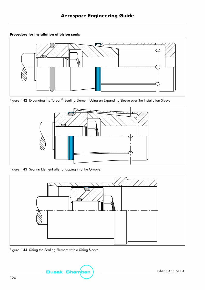
Aerospace Engineering Guide
124
Busak+ Shamban Edition April 2004
Procedure for installation of piston seals
Figure 142 Expanding the TurconR Sealing Element Using an Expanding Sleeve over the Installation Sleeve
Figure 143 Sealing Element after Snapping into the Groove
Figure 144 Sizing the Sealing Element with a Sizing Sleeve

Aerospace Engineering Guide
125
Busak+ ShambanEdition April 2004
For sizes where the TurconR seal ring is expanded morethan 15% (10% for the high filled materials TurconR T10and TurconR T29), a split groove is necessary.
Figure 145 Installation in a Split Groove
Figure 146 Fitting the Seal Ring onto the O-Ring in theGroove
Figure 147 Sizing of the Installed Seal

Aerospace Engineering Guide
126
Busak+ Shamban Edition April 2004
Procedure for installation of rod seals- Place the elastomer part into the groove- Compress the TurconR part into a kidney shape. Theseal must have no sharp bends (Figure 148)! Use arounded object like a pen to compress the TurconR
part.
Figure 148 Kidney-Shaped Deformation of the Seal Ring
Figure 149 Inserting the Seal Ring into the ClosedGroove
- After placing into the groove, form the seal into a ringagain by smoothing out the I.D. by hand.
- Finally, size the seal ring using a mandrel which shouldhave a chamfer of 10_ to 15_ over a length of approx.30 mm. (Figure 150).
The sizing mandrel should be made from a polymermaterial (e.g. polyamide) with good sliding characteristicsand high surface quality in order to avoid damage to theseals.
The piston rod itself can also be used for calibration,provided it has a sufficiently long lead-in chamfer.
rounded and polished
10_-15_
Rotate byseal contact
30
Figure 150 Sizing of the Installed Seal
Note! Should you encounter problems with installation even after following the recommendations in this catalog,additional information is available.

Aerospace Engineering Guide
127
Busak+ ShambanEdition April 2004
Quality Criteria
The cost-effective use of seals and bearings is highlyinfluenced by the quality criteria applied in production.Seals and bearings manufactured by Shamban arecontinuously monitored according to strict qualitystandards from material acquisition through to delivery.
Certification of our production plants in accordance withinternational standards EN ISO 9000 meets the specificrequirements for quality control and management ofpurchasing, production and marketing functions.
Our quality policy is consistently controlled by strictprocedures and guidelines which are implemented withinall strategic areas of the company.
All testing of materials and products is performed inaccordance with accepted test standards andspecifications, e.g. random sample testing in accordance
with DIN ISO 2859 part 1/ANSI/ASQC Z 1.4-1993/MIL-STD- 105 E. Inspection specifications correspond tostandards applicable to individual product groups (e.g.for O-Rings: ISO 3601/DIN 3771).
Our sealing materials are produced free ofchlorofluorinated hydrocarbons and carcinogenicelements.
For Seals and Bearings used in the AerospaceIndustry, an ”A” must be specified in the 10thdigit. In special numbers, the ”A” will be in the 5th digitof the number. Customer-specific demands are indicatedand monitored with other characters in those positions.
Certificates of Approval
All manufacturing companies have ISO 9001/9002 certification and all marketing companies are certified or will be inthe near future.

Aerospace Engineering Guide
128
Busak+ Shamban Edition April 2004
Storage
(The notes in italics only apply to elastomeric sealingmaterials).
Seals and bearings are often stored as spare parts forprolonged periods. With a few basic simple precautions,the shelf life of these products can be considerablylengthened.
Seals and bearings should be stored where they are safefrom damage by external influences. Deformation, inparticular, should be avoided during storage.
Under the influence of various external factors e.g. heat,moisture, light, oxygen, ozone and as a result of contactwith liquid media, the properties of certain materials maychange. For example, deformation, ageing andweathering can cause deterioration of the originalmechanical and physical properties, depending on thematerial and shape of the parts.
Fundamental instructions on storage, cleaning andmaintenance of elastomer seal elements are described ininternational standards, such as:
Storage of rubber products: DIN 7716/BS 3F68: 1977
Maximum agelimitation: New seal storage spec.: ARP 5316
MIL-HDBK-695C (Pending on cancellation)MIL-STD-1523A (Cancelled)DIN 9088
The individual guidelines give several recommendationsfor the shelf life of elastomers, depending on the materialclasses.
The following guidelines should be observed to maintainthe optimum physical and chemical values of the parts:
Heat
The ideal temperature for storage is between+5_C/41_Fand +25_C/77_F. Direct contact with heaters should beavoided.
Moisture
Parts must be stored dry under normal atmosphericconditions (65% rel. moisture ±10).
Light
To ensure that the properties of the product aremaintained, elastomer seals should be stored to avoidexposure to ultra violet or neon light.
Oxygen
To protect elastomers from oxygen, they should be kept inthe original packaging or in airtight containers.
Weathering
To protect them against damage, seals and bearingsshould be kept in the original sealed packaging.
Ozone
Destruction of certain elastomeric sealing materials due toozone can be caused by the following machines andequipment:
- Mercury discharge lamps
- High voltage equipment
- Electric motors
- Electric spark sources or discharges

Aerospace Engineering Guide
129
Busak+ ShambanEdition April 2004
Customer Approvals
A Abex/Parker/NWL, Control Systems
ABS
AEG
AERO VODOCHODY, a.s.
Aerojet Strategic Propulsion Company
Aerospatiale
Airesearch
Airlines (all major airlines)
Airscrew Howden
Allied Signal/Bendix Engine Controls QP2000
Allied Signal/Bendix Wheels & Brakes QP318
Allison Gas Turbine
Alresearch MIL-I-45208A
Alvis Aerospace & Transmission
Amsco
Anchor Darling Valve Company
ANPK ”MIG”
APPH Precision Hydraulics
Argo-Tech
Arkwin
Asdor Filters
Agusta
B Battle of Britain Flight
BF Goodritch
Boeing Company D1-9000
British Aerospace BAe/AG/QC/SC1, Part 3b
British Aerospace
BW/IP International
C Cadillac Gage
Coltax Aerospace
Compania Espanola de Sistemas Aeronauticas,S.A.(CESA)
Construcciones Aeronauticas, S.A. (CASA)
D DAF Special Products B.V.
Daimler Benz Aerospace Airbus GmbH
DLA-DCAS
Douglas Aircraft
Dowty Aerospace
Dräger Hispania S.A.
Dunlop
E EDO
Emco Fluid Systems
E.N. Santa Barbara
Energia
Ericsson Saab Avionics
F Fairey Hydraulics
Fairey Microfiltrex
Fimac
FFV Aviocomp
FFV Aerotech
Flight Refuelling
FLS Aerospace
G Gamesa Aeronautica
Garrett GmbH
GEC Marconi
General Dynamics - Top Gun Supplier
General Electric Aircraft Engine S1000
Grumman MIL-I-45208A (QES0002 - Part I)
H H R Textron
Hamilton Standard
Hispano-Suiza
Hollandse Signaalapparaten B.V.
Honeywell Space Systems
Hunting Aviation
Hughes Aircraft
Hydro-Air
Hymatic Engineering Co. Ltd

Aerospace Engineering Guide
130
Busak+ Shamban Edition April 2004
I Israel Aircraft/Astra Jet
J JIHLAVAN, a.s.
JIHOSTROJ, a.s.
K Kaman Aerospace MIL-I-45208A
Kombinat ”PZL-HYDRAL SA
Kværner
L Liebherr Aerospace Lindenberg GmbH (LLI)
LTV
Lucas Aerospace (all)
M M.L. Aviation
Magnaghi
Martin Baker Aircraft Ltd.
McDonnell Douglas
Meggitt Oxygen Systems
Messier-Bugatti
Messier-Dowty
Microtecnica
MOOG Controls
Moscow helicopter plant ”Mil”
N Normalair-Garrett Ltd.
Nuclear Assurance
O Oma
P Parker Hannifin
Pattonair
PHD
Pilatus
R Raytheon
Remco Hydraulics
Rockwell International ST0802GT0002, 20C
Rodina
Rolls Royce (ALL)
Rubin
S SABCA
Sargent Controls MIL-I-45208A
Satair
SHL
Short Brothers
Sundstrand
Swedish Space Agency
Saab Military Aircraft
Saab Aircraft
T Teijin Seiki
V/W Vickers
Volvo Aero Support
Volvo Flygmotor
Voskhod
Westlands (ALL)
Woodward Governor
Z Z.F.
ZAKLAD LOTNICZY ”PZL-MIELEC” Sp.z.o.o.
Zvezda
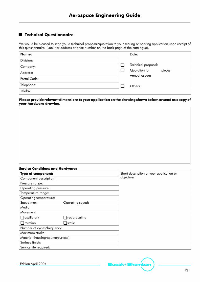
Aerospace Engineering Guide
131
Busak+ ShambanEdition April 2004
Technical Questionnaire
We would be pleased to send you a technical proposal/quotation to your sealing or bearing application upon receipt ofthis questionnaire. (Look for address and fax number on the back page of the catalogue).
Name: Date:
Division:- T h i l lCompany: - Technical proposal:
- Q t ti f iAddress:
- Quotation for pieces
Annual usage:Postal Code:
Annual usage:
Telephone: - Others:Telefax:
- O e s
Pleaseprovide relevant dimensions to your applicationon thedrawing shownbelow, or sendusa copyofyour hardware drawing.
Service Conditions and Hardware:Type of component: Short description of your application or
bComponent description:p y pp
objectives:
Pressure range:Operating pressure:Temperature range:Operating temperature:Speed max: Operating speed:Media:Movement:
-oscillatory -reciprocating
-rotation -static
Number of cycles/frequency:Maximum stroke:Material (housing/countersurface):Surface finish:Service life required:

www.busakshamban.com
99/G
B/L2
3011
/040
4
For further information:
Europe Telephone
FRANCE - Paris +33 (0) 1 30 86 56 00
GERMANY - Stuttgart +49 (711) 7 86 40
ITALY - Livorno +39 (0586) 22 61 11
SPAIN - Madrid +34 (91) 7 10 57 30
SWEDEN - Jönköping +46 (36 ) 34 15 00
UNITED KINGDOM - Ashchurch +44 (0) 16 84 85 22 11
America
AMERICAS - Fort Wayne, IN +1 (260) 7 49 96 31
BRAZIL - Sao Paulo +55 (11) 33 71 25 70
CANADA - Ontario +1 (416) 2 13 94 44
USA, Midwest - Lombard, IL +1 (630) 2 68 99 15
USA, South - N. Charleston, SC +1 (843) 7 47 76 56
USA, Southwest - Houston, TX +1 (713) 4 61 34 95
USA, West - Torrance, CA +1 (310) 3 71 10 25
Asia
JAPAN - Tokyo +81 (35) 6 10 18 11
www.trelleborg.com
For all other countries please contact via the website: Phot
o cr
edits
: ©N
HIn
dust
ries,
Bus
ak+
Sham
ban,
Fot
ostu
dio
Mos
er©
2004
Bus
ak+
Sham
ban.
Eve
ryth
ing
corr
ect
at t
ime
of p
rintin
g.