aerospace forces engine maintenance systems …iv engine maintenance systems evaluation: a user’s...
TRANSCRIPT

Project AIR FORCE
R
Prepared for the
UNITED STATES AIR FORCE
Approved for public release; distribution unlimited
Mahyar A. AmouzegarLionel A. Galway
Supporting ExpeditionaryAerospace Forces
ENGINEMAINTENANCE
SYSTEMSEVALUATION(ENMASSE)
A USER’S GUIDE

RAND is a nonprofit institution that helps improve policy anddecisionmaking through research and analysis. RAND® is aregistered trademark. RAND’s publications do not necessarily reflectthe opinions or policies of its research sponsors.
© Copyright 2003 RAND
All rights reserved. No part of this book may be reproduced in anyform by any electronic or mechanical means (includingphotocopying, recording, or information storage and retrieval)without permission in writing from RAND.
Published 2003 by RAND1700 Main Street, P.O. Box 2138, Santa Monica, CA 90407-2138
1200 South Hayes Street, Arlington, VA 22202-5050201 North Craig Street, Suite 202, Pittsburgh, PA 15213-1516
RAND URL: http://www.rand.org/To order RAND documents or to obtain additional information,
contact Distribution Services: Telephone: (310) 451-7002; Fax: (310) 451-6915; Email: [email protected]
Library of Congress Cataloging-in-Publication Data
Amouzegar, Mahyar A.Supporting expeditionary aerospace forces : engine maintenance systems
evaluation (EnMasse) : a user’s guide / Mahyar A. Amouzegar, Lionel A. Galway.p. cm.
“MR-1614.”Includes bibliographical references.ISBN 0-8330-3285-21. Jet engines—United States—Maintenance and repair—Simulation methods.
2. United States. Air Force—Equipment—Maintenance and repair—Simulation methods. 3. Airplanes, Military—United States—Maintenance and repair—Simulation methods. I. Galway, Lionel A., 1950– II.Title.
UG1103 .A48 2003623.7'06044—dc21
2002151079
The research reported here was sponsored by the United States AirForce under Contract F49642-01-C-0003. Further information maybe obtained from the Strategic Planning Division, Directorate ofPlans, Hq USAF.

iii
PREFACE
This report is a user’s guide for the Engine Maintenance SystemsEvaluation (EnMasse), a simulation model used in the analysis ofalternative concepts for Jet Engine Intermediate Maintenance(JEIM). The result of that analysis is reported in a companion docu-ment, Supporting Expeditionary Aerospace Forces: Alternatives forJet Engine Intermediate Maintenance, MR-1431-AF, 2002. This isongoing research in support of emerging Air Force employmentstrategies associated with Expeditionary Aerospace Forces (EAFs).EAF concepts rely on the premise that rapidly adaptable, quicklydeployable, immediately employable, and highly effective air andspace force packages can serve as a credible substitute for perma-nent forward presence. Success of the EAF will, to a great extent,depend on the effectiveness and efficiency of the Agile Combat Sup-port (ACS) system. This report is one of a series of RAND publica-tions that address ACS issues in implementing the EAF. Othersaddress planning, practices, policies, and technologies that canenhance the effectiveness of the EAF. Titles in this series include
•••• Expanded Analysis of LANTIRN Options (MR-1225-AF, 2001),
•••• Alternatives for Jet Engine Intermediate Maintenance (MR-1431-AF, 2002),
•••• Flexbasing: Achieving Global Presence for Expeditionary Aero-space Forces (MR-1113-AF, 2000),
•••• An Analysis of F-15 Avionics Options (MR-1174-AF, 2000)
•••• New Agile Combat Support Postures (MR-1075-AF, 2000),

iv Engine Maintenance Systems Evaluation: A User’s Guide
•••• A Concept for Evolving the Agile Combat Support/Mobility Systemof the Future (MR-1179-AF, 2000), and
•••• An Integrated Strategic Agile Combat Support Planning Frame-work (MR-1056-AF, 1999).
The research addressed in this report was conducted in the ResourceManagement Program of Project AIR FORCE (PAF) as one element ofa project entitled “Implementing an Effective Air ExpeditionaryForce.” The project was sponsored by the Air Force Deputy Chief ofStaff for Installations and Logistics (AF/IL), Air Combat Command’sDirector of Logistics (ACC/LG), and, in its early stages, jointly by theAir Force Deputy Chief of Staff for Plans and Operations (AF/XO).This report should be of interest to logisticians and operators in theAir Force concerned with implementing the EAF concept.
PROJECT AIR FORCE
Project AIR FORCE, a division of RAND, is the Air Force federallyfunded research and development center (FFRDC) for studies andanalyses. It provides the Air Force with independent analyses ofpolicy alternatives affecting the development, employment, combatreadiness, and support of current and future aerospace forces.Research is being performed in four programs: Aerospace ForceDevelopment; Manpower, Personnel, and Training; Resource Man-agement; and Strategy and Doctrine.

v
CONTENTS
Preface ......................................... iii
Figures ......................................... vii
Tables.......................................... ix
Summary ....................................... xi
Acknowledgments................................. xv
Acronyms ....................................... xvii
Chapter OneINTRODUCTION .............................. 1Jet Engine Intermediate Maintenance Under
Expeditionary Operations .................... 2Development of Simulation Model ................. 4Reasons for Selecting Modeling as the Method
of Analysis................................ 4Advantages of a Simulation Model.................. 5
Simulation Modeling .......................... 7Organization of This Report....................... 8
Chapter TwoSIMULATION OF ENGINE MAINTENANCE SYSTEMS ... 11Flightline and JEIM Maintenance .................. 11Engine Maintenance Simulation ................... 13Maintenance Alternatives and Metrics............... 14Data Sources.................................. 17
Chapter ThreeSTRUCTURE OF THE MODEL..................... 19

vi Engine Maintenance Systems Evaluation: A User’s Guide
An Overview of Hierarchical Modeling............... 22A Note on Reading the Figures ................... 23Inside the Upper Hierarchy ..................... 23Inside the Lower Hierarchies: An F-15 World Block ... 25An F-15 Base Block in Peacetime and Wartime
Scenarios................................. 27An FOL Block................................ 28A JEIM Shop Block ............................ 30
Running the Model using the Default Settings ......... 31
Chapter FourEnMasse LIBRARY.............................. 33Aircraft/Engine Selection Block..................... 33FOL Sortie Calculation Block ...................... 35Sortie Shortfall Block............................ 38Flightline Block................................ 39JEIM Shop Block ............................... 41AWP Block ................................... 43Modified JEIM Block ............................ 44Module Shop Block ............................. 45Assembly/Test Cell Block ......................... 48Spares Analysis Block ........................... 49Transportation Block ........................... 51Resource Computations Block ..................... 52FOL Block.................................... 54
Chapter FiveCONCLUSIONS AND RECOMMENDATIONS.......... 57
AppendixA. A SAMPLE RUN................................ 59B. GLOSSARY OF ENMASSE FIGURES AND ICONS ....... 67
Bibliography..................................... 83

vii
FIGURES
2.1. Closed-Loop Maintenance Flow ................ 153.1. User Interface for an FSL Model................. 213.2. Simulation Setup ........................... 223.3. An FSL Block Model (top level) ................. 243.4. An F-15 World Block with Two Air Force Bases and a
Single FOL ................................ 253.5. F-15 Base Block with a JEIM Shop ............... 263.6. An F-15 FOL Block .......................... 293.7. A JEIM Shop in a Forward Support Scenario........ 304.1. Aircraft/Engine Selection Block ................. 344.2. Aircraft/Engine Selection Block with User-Modified
Attributes ................................. 354.3. External File Input .......................... 364.4. FOL Sortie Calculation Block ................... 374.5. Modified FOL Sortie Calculation Block............ 384.6. Sortie Shortfall Block......................... 394.7. F-16 Flightline Inspection and Repair Block ........ 404.8. JEIM Shop Block in a CSL ..................... 424.9. AWP Block ................................ 43
4.10. Modified JEIM Block ......................... 444.11. Module Shop Block.......................... 464.12. Module Repair Block......................... 474.13. Core Module Repair Shop Block ................ 474.14. Assembly and Test Cell Block .................. 494.15. Spares Analysis Block at an FOL................. 504.16. Spares Analysis Block at an F-15 Base ............ 504.17. Spare Engines Deployment Block ............... 514.18. Transportation Block ........................ 52

viii Engine Maintenance Systems Evaluation: A User’s Guide
4.19. Resource Computations Block.................. 534.20. Deployment Calculations Block................. 534.21. FOL Block................................. 55A.1. Percentage of Missed Sorties at the F-16 FOL ....... 61A.2. Daily Number of Engines at the JEIM Shop ........ 62A.3. ENMCS Distribution ......................... 63A.4. Weekly Test Cell Utilization at the FSL ............ 64A.5. Serviceable Spares at an F-15 Base............... 65A.6. Serviceable Spares at the F-15 FOL .............. 65B.1. Aircraft Engine Selection ...................... 68B.2. Sortie Shortfall Block......................... 68B.3. Flight Sorties Block .......................... 68B.4. Flightline Inspection Block .................... 69B.5. Assembly and Test Cell Block .................. 69B.6. AWP Block ................................ 69B.7. Individual Module Repair ..................... 70B.8. Labor Reconstitution Block .................... 70B.9. Deployment Calculation Block ................. 71
B.10. Transportation Block ........................ 71B.11. Reset Attribute Block......................... 72B.12. Spare Engines (WRE) Deployment Block .......... 72B.13. JEIM Block at a Unit ......................... 73B.14. JEIM Block in a Deployed Location (FSL or Deployed
JEIM) .................................... 73B.15. JEIM Supporting Training and Deployed Units Block
(CSL and Home Support) ..................... 74B.16. Module Repair Block......................... 75B.17. Resource Computation Block .................. 76B.18. Spare Engines Analysis Block................... 76B.19. Deployed Location Spare Engines Analysis Block .... 77B.20. FOL Sortie Calculation Block ................... 77B.21. Module Shop Block at the Units................. 78B.22. Deployed Module Shop Block (FSL, Deployed
JEIM) .................................... 78B.23. Module Shops Supporting Training and Deployed
Units (CSL, Home Support) .................... 79B.24. Engine Maintenance at an FSL or an FOL.......... 79B.25. Engine Maintenance at a CSL .................. 80B.26. MDS-Based Unit Block ....................... 80B.27. FOL Block................................. 81

ix
TABLES
A.1. Spares and WREs at the Units .................. 60A.2. F-16 Engine Demography ..................... 60A.3. Aircraft Requirements at the Units and the FOLs .... 61

xi
SUMMARY
This report is a user’s guide for the Engine Maintenance SystemsEvaluation (EnMasse). EnMasse is a simulation model based onExtend software and used in the analysis of alternative Jet EngineIntermediate Maintenance (JEIM) policies. The result of the policyanalysis conducted using EnMasse is reported in a companion doc-ument, Supporting Expeditionary Aerospace Forces: Alternatives forJet Engine Intermediate Maintenance, MR-1431-AF, 2002.
The goal of the analysis was to evaluate several alternatives foraccomplishing JEIM support. Closely allied to maintenance policyare the maintenance structures within which these policies operateboth in peace and war.
In terms of modeling and simulation, we are interested in the flow ofentities (e.g., spare engines, personnel), the state of the system (e.g.,engines not mission capable, spares inventory), and the processes(e.g., service time, sortie rates). EnMasse’s structure is based on a setof hierarchical, functional blocks that generate and modify entities,processes, and attributes. These blocks represent Air Force homebases, flightlines, JEIM shops, module shops, test cells, forward sup-port locations (FSLs), and forward operating locations (FOLs). Thisreport is not a traditional user’s guide in that it does not aim to givethe user an exhaustive list of model inputs and outputs, but rather itsgoal is to allow the user to examine the model using the GraphicalUser Interface (GUI) and determine and modify functions from thatvantage point.
In general, EnMasse is based on the following sequence of events:aircraft are flown from home bases and FOLs to meet peacetime

xii Engine Maintenance Systems Evaluation: A User’s Guide
(training) and wartime flying schedules, respectively. After eachmission, the aircraft and their engines are inspected at the flightline,and in most cases they are fully operational within hours. However,when engines accumulate enough flying hours, or when unsched-uled maintenance is required, they are removed from the planes andsent to a JEIM facility. They are then inspected, repaired, tested, andreturned to service. The JEIM facility includes the JEIM shop, themodule shop, and the assembly and test cell.
The first requirement for each model is the number and types of air-craft (e.g., F-15, F-16), and the number and ages of the installedengines. Both aircraft and engines are required to form fully missioncapable (FMC) aircraft.
After each sortie, aircraft are sent to the Flightline block where theyare inspected and maintained. Each aircraft that passes theinspection is sent back to the pool of available aircraft. Some aircraftrequire minor repairs, which are performed on the flightline.EnMasse also allows for scheduled and unscheduled maintenance.The number of engines pulled from the aircraft is a function of theage and the type of the engine. The detached engines are taggedaccording to the removal type and sent to the JEIM shop. Aircrafttagged as not mission capable (NMC) are sent to the Spare EnginesAnalysis block where they are queued for the next available engine. Ifserviceable spares are available, these aircraft are put back intoservice immediately. Otherwise, they await the arrival of enginesfrom the Assembly and Test Cell block.
The JEIM Shop block requires two inputs from the user: the initialnumber of labor units and the number of rails (i.e., the JEIM capac-ity). Engines are queued in two parallel lines, the first for enginesthat require parts that are not available and the other for engines thatawait maintenance. The modular engines that have been processedby the JEIM shop are sent to the Module Shop block.
Engines that enter the Module shop are separated into five modules:fans, core, low-pressure turbine (LPT), augmentor, and gearbox.Engines that leave the module shop are sent to the Assembly and TestCell block. In this block, engines are queued for assembly, the testcell and the final inspection. After assembly and test cell, engines aresent to the Spare Engines Analysis block. In this block, the FMC

Summary xiii
engines are pooled with the other spares (including the war reserveengines) and queued for installation on the aircraft. The FMCaircraft leave this block to join the pool of other aircraft, and thewhole cycle starts again.

xv
ACKNOWLEDGMENTS
The research documented in this report could not have been donewithout the active cooperation and help of a large number of AirForce people. In these acknowledgments we list their positionswhen the study was done.
Much of the RAND work on Expeditionary Aerospace Force supporthas been done under the sponsorship of several different DeputyChiefs of Staff for Installations and Logistics (AF/IL). Much of thiswork was done when Lt Gen John W. Handy held this position. Ourpoint of contact with AF/IL was primarily Susan O’Neal (AF/ILX),who together with her staff provided much useful guidance,information, and contacts with other Air Force organizations. Asdescribed in the report, this particular project was co-sponsored byACC/LG Maj Gen Dennis Haines. We are particularly indebted toACC/LGSP for its help and involvement as our point of contact withACC, especially Col Stanley Stevens, Lt Col John Cooper, CMSgtHank Houtman, CMSgt Michael Kinser, and ACC Command EngineManager Tom Smith. Data were also provided by ACC/LGP, underthe direction of Ed Merry.
At San Antonio Air Logistics Center, we would like to thank RobertMay (SA-ALC/LR) and his staff, particularly Melissa Tinscher andChris Szczepan, for information on engine requirements. We alsobenefited from discussions with SA-ALC/LPF, Colonel Doumit andhis staff, especially Colonel McMahon, Greg Hall, Bruce Eberhard,and David Crowley.
For access to and patient help with data from the ComprehensiveEngine Management System, we are grateful to Charlie Osborn, Phil

xvi Engine Maintenance Systems Evaluation: A User’s Guide
Garrity, Jim Blain, David Addison, and Walt Cooper. For help withaccess to and interpretation of data from the Reliability andMaintainability Information System (REMIS), we appreciate the helpof Richard Enz and Thomas Recktenwalt.
We had extensive help from a number of JEIM shops and their seniorNCOs. These include SMSgt Kasprak at the 1st Fighter Wing (Langley AFB, Va.), SMSgt McDyer at the 20th Fighter Wing (Shaw AFB,S.C.), SMSgt Dotten 347th Fighter Wing (Moody AFB, Ga.), SMSgtTravis at the 366th Fighter Wing (Mountain Home AFB, Idaho),CMSgt Mackey at the 48th Fighter Wing (RAF Lakenheath, UK),SMSgt Gasper at the 31st Fighter Wing (Aviano AB, Italy), andCMSgt Holas at the 52nd Fighter Wing (Spangdahlem AB, Germany).All of these very busy people and their staffs graciously organizedtours of their shops and meetings with their supervisors, collecteddata and information on their operations, and fielded clarificationquestions after our visits. This project also drew on a discussion withCMSgt Hauck at USAFE headquarters on engine support duringOperation Noble Anvil.
Finally, we appreciate the hospitality of the Air Force Research Labo-ratory at Wright-Patterson AFB, Ohio, for a day of discussions on newpropulsion technologies.
As always, we benefited greatly during our project from the com-ments and constructive criticism of many RAND colleagues, includ-ing Laura Baldwin, Richard Moore, C. Robert Roll, and HymanShulman. We owe special thanks to Robert Tripp, the project leaderfor all of the EAF support tasks, for his guidance and support and toLouis Miller for his insightful comments on building a robust simu-lation model. Marygail Brauner provided detailed reviews of drafts ofthis work that substantially improved the quality and the presenta-tion. Frances Teague and Kristin Leuschner patiently and promptlydid an excellent job editing the document.
Our modeling in this project was done with Extend simulation soft-ware. We had very good technical support from author Bob Dia-mond and his people at Imagine That, Inc., in San Jose, Calif.

xvii
ACRONYMS
ACC Air Combat Command
ACS Agile Combat Support
AEF Aerospace Expeditionary Force
AETC Air Education and Training Command
AFB Air Force Base
AFLMA Air Force Logistics Management Agency
AFMC Air Force Materiel Command
ALC Air Logistics Center
ANG Air National Guard
AWM Awaiting maintenance
AWP Awaiting parts
CAMS Core Automated Maintenance System
CEMS Comprehensive Engine Management System
CIRF Centralized Intermediate Repair Facility
CONUS Continental United States
CSL CONUS support location
EAF Expeditionary Aerospace Force

xviii Engine Maintenance Systems Evaluation: A User’s Guide
EMB Engine Management Branch
EnMasse Engine Maintenance Systems Evaluation
ENMCM Engine not mission capable because ofmaintenance
ENMCS Engine not mission capable because of supply
FCFS First come, first served
FIFO First in, first out
FMC Fully mission capable
FOD Foreign object damage
FOL Forward operating location
FSL Forward support location
GUI Graphical User Interface
JEIM Jet Engine Intermediate Maintenance
LANTIRN Low-Altitude Navigation and TargetingInfrared for Night
LPT Low-pressure turbine
MAJCOM Major Command
MDS Mission Design Series
MTW Major theater war
NMC Not mission capable
OSD Office of the Secretary of Defense
PAA Primary Aircraft Authorized
PRS Propulsion Requirements System
REMIS Reliability and Maintainability InformationSystem
Acronyms xix
SER Scheduled engine removal (rate)
SSC Smaller-scale contingency
SWA Southwest Asia
TAMS Tactical Aircraft Maintenance Specialists
TC Test Cell
TCTO Time Change Technical Order
UER Unscheduled engine removal (rate)
USAFE U.S. Air Forces in Europe
UTC Unit Type Code
WRE War reserve engine

1
Chapter One
INTRODUCTION
This report provides a detailed guide to Engine Maintenance SystemsEvaluation (EnMasse), a simulation model developed by RAND toanalyze jet engine intermediate maintenance alternatives for the U.S.Air Force.
This analysis was prompted by the ongoing reorganization of the AirForce into an Expeditionary Aerospace Force (EAF). The main objec-tive of this reorganization is to replace the forward presence of airpower with a force that can deploy quickly from the continentalUnited States (CONUS) in response to a crisis, commence operationsimmediately on arrival, and sustain those operations as needed. Tosupport the expeditionary force, such support processes as muni-tions, fuels, and maintenance also need to be transformed. EAFrequires a combat support system capable of supporting anexpanded range of operations, including major theater wars andsmaller-scale contingencies (SSCs), which could take place in any ofa number of different locations.1
Since 1997, RAND has conducted a series of studies for the Air Forceto understand how combat support can be adapted for expeditionaryoperations.2 The most important finding of the work to date is thatthe Air Force’s original goal of deploying a complete package ofcombat aircraft and support within 48 hours to an unprepared (“bare
______________ 1For a more complete description of the EAF concept and its history, see Davis (1998)and Ryan (1998).2See Galway et al. (2000); Tripp et al. (2000); Feinberg et al. (2001); and Peltz et al.(2000).

2 Engine Maintenance Systems Evaluation: A User’s Guide
base”) forward operating location (FOL) cannot be met with currentsupport processes. The timeline can be met only with judiciousprepositioning of materiel at the FOLs and the establishment of for-ward support locations (FSLs) for storage and maintenance ofselected commodities. Complete deployed support can be providedfor fighter units from CONUS only by accepting a timeline on theorder of a week or more.
JET ENGINE INTERMEDIATE MAINTENANCE UNDEREXPEDITIONARY OPERATIONS
The analysis of support strategies for the EAF has subsequently beenextended to other critical processes to determine where they shouldbe located. One of these critical processes is Jet Engine IntermediateMaintenance (JEIM), which provides combat units with extensiverepair of jet engines. The JEIM facility consists of several compo-nents, including the JEIM shop, the module shop, and the assemblyand test cell. JEIM is one of three levels of maintenance used by theAir Force to repair jet engines, especially those powering fighter air-craft:
• Flightline maintenance consists mostly of inspections, diagnos-tics, engine removals, and some quick repairs that do not involveengine teardown.
• Intermediate maintenance at the JEIM facility includes disas-sembly of the engines; substantial repairs to such parts as fans,low-pressure turbines (LPTs), and afterburners; and engine testcell runs.
• Depot maintenance involves the complete teardown and refur-bishment of any repairable part in an engine. The rebuilding ofan engine at the depot allows the engine’s use parameters (flighttime, cycles, etc.) effectively to be reset at zero.
Traditionally, the JEIM has been located at the operating base withthe aircraft and under the overall command of the operational com-

Introduction 3
mander.3 This practice stemmed from the long-held concept thatthe operational commander should have control of all of theresources needed to generate required sorties and that the unitshould be relatively self-sufficient in combat and combat-supportcapability for a period of weeks. This policy was reinforced by theplanning for major wars in Europe and Korea: A unit would bemoved to existing bases in theater in preparation for immediateaction and could expect little resupply during the first few weeks ofcombat. Under traditional planning for wing deployment, therefore,the JEIM is prepared to move along with the rest of the wing support,although not with the combat units themselves, who will use sparesto replace engines until the JEIM arrives and is up and running.
In recent years, the question of whether JEIM operations should becentralized has been the subject of frequent discussion in the AirForce engine community. Many factors favored centralization,including the increased complexity of engines and the largeinvestment required for repair facilities. Other factors workedagainst centralization, particularly the fact that, unlike such othercommodities as avionics components, engines are heavy and bulkyand thus require special packing to ship. Over the years, the AirForce has experienced a pattern of alternation between the partialcentralization of JEIM operations—in certain regions and for certainengine types—and the subsequent restoration of JEIM facilities tooperating units.
The requirements associated with expeditionary operations—includ-ing the ability to move quickly, the need to keep initial transportationrequirements down—have raised new questions about the policy oflocating the JEIM facility at the operating base. Our current researchaims to provide insights into this issue by determining whether JEIMsupport can best be provided from decentralized shops at the sup-ported bases or from a centralized, off-base facility. The results ofthis analysis are reported in a companion document, SupportingExpeditionary Aerospace Forces: Alternatives for Jet Engine Intermedi-ate Maintenance, MR-1431-AF, 2002.
______________ 3For very reliable engines, especially those in transport aircraft, which spend largeamounts of time away from their home bases, the JEIM has sometimes been located ina regional or “Queen Bee” facility.

4 Engine Maintenance Systems Evaluation: A User’s Guide
DEVELOPMENT OF SIMULATION MODEL
This report focuses on the suite of simulation models we developedto understand and evaluate the support alternatives for the JEIM.These models, referred to collectively as EnMasse, were createdusing a system and process modeling software package known asExtend.4 EnMasse offers dynamic modeling capabilities that allowthe user to create a realistic simulation of the jet engine repair sys-tem. It simulates the interaction among the components of themaintenance system, while incorporating the random variations oruncertainties typical of a dynamic system. Using EnMasse, we couldanalyze a number of possible support configurations for the JEIM,involving various combinations of centralized and decentralizedlocations. The simulation models allowed us to compare severalalternatives for maintenance support across different scenarios.
This report focuses on the development, use, and modification of theEnMasse simulation model in analyzing maintenance alternatives.Our objective is to provide a basic understanding of the key featuresand capabilities of EnMasse. Although the report includes someinformation about the use of Extend, it is not intended as a softwareuser’s manual. Readers interested in learning more about thecapabilities and functioning of Extend should refer to the Extenduser’s manual.5
REASONS FOR SELECTING MODELING AS THE METHOD OFANALYSIS
In this section we describe our reasons for developing a fairly com-plex simulation model as the primary means of analyzing alterna-tives for JEIM support. The simulation model provides severaladvantages for analyzing and comparing jet engine maintenancesupport options.
As stated earlier, our aim in this project was to compare severalalternatives for locating the JEIM. These alternatives included fullcentralization in peace and war, as well as several hybrid systems
______________ 4Extend was created by Imagine That, Inc.5For more information, see www.imaginethat.com.

Introduction 5
(e.g., decentralized in peace but centralized in the theater of opera-tions). The alternatives were to be compared using several perfor-mance metrics and potentially several different scenarios as well. Wecould have used two main approaches for this analysis:
• Use data from the previous history of centralization attempts todetermine whether centralization will work.
• Develop a model of the JEIM and supporting systems, such astransportation, and evaluate the alternatives within the model.
In our view, the history of centralization was of limited use in assess-ing JEIM alternatives. In many of the historical centralizationefforts—both successful and unsuccessful—decisions about locationwere driven by external constraints, which may not apply in generalsituations. Moreover, limited data were available on pre- and post-centralization performance, and no information was available on anyof the major centralized facilities during a conflict. This is not sur-prising because almost no centralized facility has supported a con-flict as the major source of repair. We also wanted to examine theeffects of centralizing intermediate repair for engines that had neverhad centralized repair (e.g., the F100-229), to look at full centraliza-tion of engines that had partially centralized repair (e.g., the TF-34),and to look at engines for which centralization had failed (e.g., theF100-220).
For all these reasons, we turned to modeling as our primary tool forthe analysis. In developing the model, however, we drew on the his-tory of past centralization efforts in selecting the alternatives to beanalyzed and understanding some of the key factors that have tradi-tionally caused problems in centralized repair.
ADVANTAGES OF A SIMULATION MODEL
Our next step was to determine which kind of model would best suitour objectives. One option we considered was an “expected value”model, which uses the means of stochastic quantities (e.g., trans-portation times) in deterministic formulas, which are supplemented

6 Engine Maintenance Systems Evaluation: A User’s Guide
by uncertainty computations, such as confidence limits. Much pre-vious RAND work in support of the EAF has used this type of model.6
Another option, and the one we chose, was a simulation model.Unlike expected-value models, a simulation model is capable ofdirectly incorporating aspects of uncertainty. For our purposes, asimulation seemed advantageous for several reasons:
• Accommodation of dynamic metrics. The metrics in which wewere potentially interested—sorties missed, current spare levels,queue sizes at key shop points, etc.—are inherently dynamic,and we wanted to see the value of key metrics day by day. Forexample, during conflict situations, sortie requirements maychange. Under such circumstances, a force may miss only 5 per-cent of required sorties, but there is a big difference in perfor-mance if that 5 percent is concentrated during the first few daysof a war rather than at the end of a conflict.
• Flexibility in setting time dimensions for the analysis. Man-agement decisions about engine deployment and repair areregularly based on the time characteristics of individual engines.For example, when a unit is deploying for operations away fromhome, the propulsion flight supervisors try to select thoseengines with the most time remaining until major inspections orother work.
• The ability to include engine “demographics” in the analysis.Demographics refer to the age distribution in terms of suchparameters as cumulative flying hours. Engine demographicsdrive the inspection and removal of many critical components ofthe engine and are key to the performance of the repair system.Depot repair, as noted above, usually “zero-times” the engine.The distribution of engine ages at a particular point is an impor-tant determinant of JEIM (and depot) workload. Conversely,modifying workload can manipulate the age distribution.
• Variability in setting repair “modes” in order to analyze theirimpacts. Some engines have several repair “modes,” dependingon whether an engine removal is scheduled (for an inspection or
______________ 6See Feinberg et al. (2001) and Peltz et al. (2000).
Introduction 7
to change a part that has reached a specific age) or unscheduled(due to a malfunction of some type). In addition, for some typesof engines, such as the TF-34, the engine repair can either be aquick-turnaround repair or a more complete disassembly. Theproportion of each type of repair can have different effects on theinternal work flow of the shop.
• The ability to analyze potential transportation options at arelatively high level of detail and to incorporate other trans-portation variables in addition to transportation times. Thesevariables include limited transportation capacity, transportationschedules, and such options as waiting until two engines need tobe shipped to minimize shipping costs.
In addition to these considerations, some initial experimentationindicated that current Graphical User Interface–based7 simulationpackages could indeed provide us with a simulation that ran in rea-sonable times when simulating repair operations for current fighterengine fleets.
Simulation Modeling
All of these considerations led to our decision to build a simulationmodel. Although the model required a substantial investment in ini-tial effort, the result was a flexible tool that could be used for this andfuture investigations.
Simulation models, such as EnMasse, attempt to predict the behav-ior of the system under investigation by replicating and analyzing theinteraction among its components. In the past, one had to com-promise between choosing a model that provided a realistic replicaof the actual situation and one whose mathematical analysis wastractable. With the advent of faster computers and increased mem-ory, we can develop a more realistic reflection of reality withoutcompromising on mathematical rigor.
By expressing the interactions among the components of the systemas mathematical relationships, we can gather information in much
______________ 7GUI enables a wider access to the power of the digital computer.

8 Engine Maintenance Systems Evaluation: A User’s Guide
the same way as if we were observing the real system (subject, ofcourse, to the simplifications built into the model). Simulation thusallows greater flexibility in representing complex systems that arenormally difficult to analyze by standard mathematical models. Wemust keep in mind, however, that a model by definition is not thereal world, but its reflection. No matter how hard we try, we will missmany nuances of the real world. In the end, we must make somecompromises to get reasonable results. We can reduce the effect ofsuch compromises, as we have done in the main study, by additionalanalysis of the problem.8
ORGANIZATION OF THIS REPORT
Traditionally, documents that describe themselves as “user’s guides”for simulation programs have a generic structure. They begin with adescription of the real-world process being modeled; explain a bitabout key algorithms in the model (random number distributions,queue disciplines), especially where they embody assumptions andapproximations; and then provide a detailed and exhaustive catalogof model inputs and outputs. In some cases, this is supplemented byprogram flowcharts and actual code listings, but for large, complexmodels inclusion of this latter material is quite rare.9
Because we use a state-of-the-art, GUI modeling language, thisreport is somewhat different. First, the model itself is largelyisomorphic to the real-world system: The shops in the JEIM areidentifiable entities in the model, as is the transportation system andthe flightline. In most cases, a user can therefore “read the code”directly by knowing what the real-world system looks like. Byimplication, it is unnecessary for us to document each instance whena random number generator is used or what the discipline for aparticular queue is. Similarly the flow of engines and informationinto and out of each block of the simulation can be determined fromthe model itself. In short, “reading the code” is now feasible as a wayof understanding a particular model.
______________ 8For the result of this analysis, see Amouzegar, Galway, and Geller (2002).9For an outstanding example, see Isaacson and Boren (1993).

Introduction 9
Our first goal is therefore to describe in some detail the real-worldsystem we are modeling, namely the operation of the JEIM. We thendescribe how we have represented the functions of the JEIM, theflightline, the transportation system, and other key elements asExtend structures (queues, decisions, etc.). This is done at a fairlyhigh level with enough detail for a user to understand our majorassumptions and approximations. The ultimate goal is that a usercan take our Extend blocks and combine them into a structure forJEIMs that will allow its performance to be simulated and henceevaluated. In many cases, that will require some modifications, butour description should allow an Extend user to find the relevantblocks and modify them. Unlike the case with traditional guides, wedo not anticipate that a user would try to run an EnMasse model byusing the information here alone. Instead, this would form the basisfor an understanding of the code. This implies that a reader wouldhave some basic familiarity with the elements of Extend (or has amanual available). For example, we often comment that a particularblock can be edited to change parameters, etc. This is an Extendoperation in which the user double-clicks on a block and opens adialogue block, which contains the parameters and allows them to bemodified as with any text.
The remainder of the report is organized as follows. Chapter Twoprovides a detailed description of JEIM maintenance support optionsand an overview of the simulation. Chapter Three focuses on thestructure of the model. Chapter Four describes the components ofthe EnMasse library and the steps in building various functioningmodels. It also illustrates how the existing library can be modified toaccommodate alternative models.
Appendix A presents a sample run of the model, and Appendix Billustrates detailed diagrams of the blocks in the EnMasse library.

11
Chapter Two
SIMULATION OF ENGINE MAINTENANCE SYSTEMS
This chapter provides an overview of the simulation model. First, wesketch out the overall requirements of the analytical model bydescribing the key components of the flightline and JEIM activities tobe replicated in the simulation. We then take a look at the model’sfunctions and describe the maintenance alternatives assessed withthe model and the metrics used to evaluate the results.
FLIGHTLINE AND JEIM MAINTENANCE
A brief review of the key components and functions of the flightlineand JEIM operations will provide a foundation for the discussion ofthe simulation.
As noted in the Chapter One, the flightline provides inspections,diagnostics, and quick repairs, while the JEIM is responsible for off-equipment engine maintenance that does not involve completeteardown and rebuilding. In many instances, the JEIM assists theflightline as well.
Flightline maintenance includes servicing, repairs, cycle recording,and tracking, which are coordinated with the Engine ManagementBranch (EMB) and JEIM. On the flightline, installed aircraft enginesare serviced daily by the Tactical Aircraft Maintenance Specialists(TAMS). Flightline activities include servicing the oil, inspecting thechip detectors, and entering the intakes and augmentor to inspectfor foreign object damage (FOD) and external engine damage. Inaddition, engine cycles are recorded in the Comprehensive EngineManagement System (CEMS) database. CEMS enables the EMB to
12 Engine Maintenance Systems Evaluation: A User’s Guide
monitor usage of engines and modules (when used) to determine theneed for inspections and Time Change Technical Orders (TCTOs).The flightline also performs all engine removals and installations.After the flightline removes an engine for maintenance at the JEIM, itsometimes performs sheet-metal work on the engine bay andreplaces some of the hydraulic lines and cables in the aircraft enginebay that have been damaged due to chafing, cracks, or heat.
The JEIM is responsible for both scheduled and unscheduled off-equipment engine maintenance. Scheduled maintenance includesmodule time changes, TCTOs, and other inspections and repairs.Unscheduled maintenance consists primarily of performance-related problems that either cannot be corrected by the flightline orare beyond their capabilities per Technical Order. For unscheduledmaintenance, the JEIM shop often performs a preliminary test cellrun to troubleshoot the engine and identify potential problems. TheJEIM is capable of replacing any module in a modular engine andalso repairs some of the modules while sending others to the depot.It is also responsible for packing engines for transportation.
The JEIM operates the engine test cell facility and functions. As partof this, the JEIM transports engines, hooks up cables and fuel lines,conducts pre- and postrun engine inspections, disconnects cablesand fuel lines, and transports the engines to the JEIM shop.
In many cases, the JEIM is also a source of expertise to back up theflightline and provide quick response repair or cannibalizing keyparts as needed. The collocation of JEIM with fighter squadrons hasresulted in a slight blurring of the functions of the two lower repairlevels. However, only personnel from the wing JEIM are authorizedto sign off on JEIM-level repair work for the wing’s engines.
The JEIM is staffed by the propulsion flight (usually a part of theComponent Repair Squadron). This organization is quite large (100–150 people for a fighter wing) and occupies an industrial spaceequipped with five or more work bays of 1,500 square feet each, anoverhead crane, supply storage, backshops for specialized repairactivities, and a test cell. The test cell is typically located off site in a“hush house,” where a fully assembled engine can be run at fullpower for testing purposes.
The general flow of JEIM work is as follows:

Simulation of Engine Maintenance Systems 13
• receive engine from the flightline;
• perform TCTO and time change check;
• perform CEMS history check;
• create job in Core Automated Maintenance System (CAMS);
• assign engine to a crew;
• determine required repairs;
• decide on complete or partial disassembly;
• conduct other inspections;
• conduct teardown;
• perform JEIM repair and maintenance;
• perform module work, if needed, at module shop;
• assemble engine;
• send to test cell (hush house); and
• conduct final inspection.
ENGINE MAINTENANCE SIMULATION
We now provide an overview of the EnMasse simulation. The firststep in constructing the simulation model was to express the realsystem in terms of its key events. An event is defined as a time atwhich changes in the character of the system take place. For exam-ple, an arrival of an NMC engine to the JEIM shop is an event in theengine maintenance system.
Each model in EnMasse is based on a basic sequence of events. First,aircraft are flown from bases and FOLs to meet peacetime (training)and wartime flying schedules, respectively. After each mission, theaircraft and their engines are inspected at the flightline and in mostcases are fully operational within hours. However, when enginesaccumulate enough flying hours,1 or when unscheduled mainte-
______________ 1The model keeps track of engine serial numbers and aircraft tail numbers throughoutthe simulation.

14 Engine Maintenance Systems Evaluation: A User’s Guide
nance is required, they are removed from the planes and sent to aJEIM facility, which includes the JEIM shop, the module shop, andthe assembly and test cell. After arrival at the JEIM shop, engines areinspected, repaired, tested, and returned to service.
As indicated by Figure 2.1, EnMasse is a closed-loop, discrete-eventsimulation model. A closed-loop model implies that entities (e.g.,engines, personnel) never enter or leave the model although the stateof the system (the occurrence of events) changes at random times.While engines, aircraft, or people may move from bases to FOLs orcentralized repair facilities, the total number of such entities in thesystem is fixed. This closed-loop property has important implica-tions for the dynamic interactions between repair and usage. Forexample, if an engine shop can fix more engines, then fewer aircraftwill have holes. As a result, fewer sorties will be missed because ofengine unavailability, and therefore a greater number of engines willbe used. However, the increase in utilization could increase thenumber of engines failing, which in turn would put pressure on theengine shop and ultimately reduce its production rate. The decreasein production would have an effect (excluding the effect of spares) onflying hours, which in turn could reduce the number of engines fail-ing. EnMasse can capture the dynamic nature of such relationshipswithin the maintenance system.
MAINTENANCE ALTERNATIVES AND METRICS
Using EnMasse, we analyzed a number of possible support configu-rations for the JEIM that involved various combinations of central-ized and decentralized locations. Centralized maintenance struc-tures include FSLs, while decentralized locations include home basesupport and maintenance at FOLs. Each structure was assessedunder both wartime and peacetime scenarios.
Here we describe in detail the specific JEIM alternatives we evaluatein this analysis:2
______________ 2We label each alternative in terms of “peacetime repair–wartime repair.” For exam-ple, the decentralized-deployed case implies a decentralized mode of repair duringpeacetime (and for nonengaged forces) at home units and deployed JEIM shops at theFOLs.

Simulation of Engine Maintenance Systems 15
Figure 2.1—Closed-Loop Maintenance Flow
• Decentralized-Deployed. In this alternative (which is the currentplan for deployed engine support), peacetime maintenance isprovided by JEIMs at each base. When part of a unit is deployed,part of that unit’s JEIM deploys to the appropriate FOL to form adeployed JEIM. According to current plans, the JEIM deploys byday 30 of the war and begins working immediately, but the testcell is not ready to test repaired engines until day 60.3 The trans-
______________ 3This limitation stems from the requirement that the test cell foundation must bestrong enough to resist the thrust of modern fighter engines at full military power

16 Engine Maintenance Systems Evaluation: A User’s Guide
portation requirement for this alternative is that needed todeploy the JEIM itself.
• Decentralized–No Deployment. As with the previous alternative,each of the peacetime bases has its own JEIM, but in this case thehome JEIM supports any deployed forces from its unit as well.4
The home JEIM is sized to have the resources to support bothpeacetime and wartime flying.
• Decentralized-FSL. As with the previous two alternatives, eachpeacetime base has its own JEIM, but, when the units deploy,some of the JEIM personnel (but not their equipment) deploy toa single FSL in-theater from which all deployed units are sup-ported. We assume that the FSL is “lukewarm”—i.e., it is ready tobegin operations as soon as the JEIM personnel arrive. In thiscase, no additional delay occurs for the test cell setup but theremay be some delay for the arrival of the personnel.
• CONUS Support Location–FSL (CSL-FSL). In this alternative, allunits are supported in peacetime by a CSL, which deploys per-sonnel to an FSL in-theater when conflict occurs. In peacetime,the CSL is staffed with the sum of the rail teams5 needed fordeployment and those required to keep the nonengaged forcesflying. (Note that for deployed forces, this alternative and theprevious one are indistinguishable because the repair structurein-theater is identical.)
• CSL. In this last alternative, all units everywhere are supportedby a single CSL both during peacetime and during deployment.
During the simulations, we evaluated each of these alternatives usingthree broad metrics. The first is performance: Does the alternativeprovide the required support for operational flying? In peacetime,this means maintaining the requisite flying hours for pilot training; inwartime, it means meeting the required number of sorties day by
_____________________________________________________________ (afterburner—about 29,000 pounds of thrust for the F100-229). The foundation is aconcrete slab, which must set for 30 days after pouring.4Note that some units use this method today to support their deployments to Opera-tions Northern Watch and Southern Watch (enforcement of Iraqi no-fly zones).5The engines are mounted on structures called “rails” for repair. A rail team is definedas the minimum number of personnel needed to work on an engine in a two-shift day.

Simulation of Engine Maintenance Systems 17
day. The second metric is resources: What does the alternativerequire to provide adequate performance? For jet engines, one of thekey resources is spare engines, which can provide a hedge againstuncertainties. Other resources are personnel and transportationcosts, and the evaluation provides an indication of the trade-offbetween these two. The third metric is uncertainty: How well doesthe alternative respond to unforeseen events? For this metric, weevaluate how robust the alternatives are to changes in the engineremoval rate. EnMasse allowed us to compare alternatives in allthree areas.
DATA SOURCES
Many of the inputs to the model were provided by analysis of datadrawn from CEMS, Reliability and Maintainability ManagementInformation System (REMIS), which rolls up data from the base-levelCAMS, as well as data in both electronic and paper form provided bythe units we visited.
The CEMS data provided information on total repair time for indi-vidual engines, engine NMC because of supply (ENMCS) times, andtransportation times for such engines as the TF-34 for which ShawAFB, S.C., provides JEIM repairs for some operational bases. REMISprovided a check on the CEMS data for overall engine repair andprovided repair data for module work. However, neither could easilyprovide information linking module work to specific engines. CEMSstarted tracking module repair recently, and data series sufficient foranalysis will be available in a couple of years. REMIS has space forthe engine serial number in the module repair records, but the fieldis seldom used. We sought overall counts from REMIS of modulerepairs per engine inducted into the JEIM, but these were deemedunreliable because it was difficult to distinguish between scheduledand unscheduled work (many jobs are a mix, and the job is oftencoded as unscheduled work when it is started). For these reasons,module repair is an area of our modeling that requires more work.
The following chapter examines the structure of the model in detail.

19
Chapter Three
STRUCTURE OF THE MODEL
In this chapter, we demonstrate how to set up and run EnMasseusing the FSL model for the JEIM shop supporting F-16 and F-15 air-craft carrying F100-229 engines.1 EnMasse is a library of severalmodules that can be combined to develop scenario-specific enginemaintenance models. Each module may receive data as an internalparameter (from user input and default settings) or from the outputof another module. Some of the internal parameters are a functionof types of engines or aircraft being simulated, while others, such asthe number of aircraft, number of spares, etc., depend on the sce-nario being tested and are set by the user.2
Figure 3.13 illustrates the required user’s input for a model in whichunits are supported at home base by their own JEIM and duringdeployment by an FSL in-theater. The FSL supports four bases: twoF-16s (bases 1 and 2) and two F-15s (bases 3 and 4). The user must
______________ 1The steps for all the other scenarios are very similar to the FSL model. However, anydifferences will be highlighted below.2The specific values were those used in the substantive study referenced above(Amouzegar, Galway, and Geller, 2002). Detailed explanations of how these valueswere derived can be found in that reference.3Figure 3.1 is an example of an Extend notebook. In Extend, each instance of a blockcontains the parameters needed to control that block—e.g., parameters for a randomnumber generator, service times for queues. This is convenient when programmingbut inconvenient for changing parameters across the model: a user would have toaccess each individual block and make detailed parameter changes. Extend note-books link a single “control panel” to all blocks of interest and allow all relevantparameters to be changed from a single location. In this figure, the parameters illus-trated are those that were of interest to the substantive study. Another user mightwant to modify the notebook to change other parameters.

20 Engine Maintenance Systems Evaluation: A User’s Guide
decide on the number of aircraft and engines (e.g., 18 F-16s in eachof bases 1 and 2, and 18 and 48 F-15s in bases 3 and 4, respectively),the sizes of the home JEIM (two units at base 1, one unit at base 2,three units at base 3, and seven units at base 4) and the module shop(two, one, four, and eight at bases 1–4, respectively), and the numberof serviceable spares available at each unit (four, ten, twelve, and 24at each respective base). Deployment inputs include three timeentries, which are calculated based on a simulation start on day 1:when aircraft are deployed (day 360 for each unit),4 when operationsshould commence (day 365 at both FOLs), and when they shouldterminate (day 465). Other deployment inputs include the numberof aircraft needed from each unit (about two-thirds) as well as thetime (day 360) and the number of spare engines (one, three, three,and eight, respectively) and labor units5 (one, zero, one, and threefrom each JEIM shop and two, zero, two, and two from each moduleshop to the FSL).
The user must also decide on the number of prepositioned assets(two units at the JEIM shop and four at the MOD shop) and, finally,the transportation time from FOLs to the FSL (two days, one way).
Once the required user inputs have been entered, the next step is todecide on the duration of the simulation and the number of runs.The standard Extend pull-down menu can be used for this task. Itcan be located by clicking on the Run menu and then selecting Simu-lation Setup. Figure 3.2 illustrates the Simulation Setup menu. Thesimulation time should be entered in days (two years was used forthe F100 engines).
If the user is satisfied with the model setup, no other input isrequired at this point, and EnMasse can start the simulation.
The rest of this chapter explains the hierarchical structure of themodel and describes the inner workings of some of the modules,including special settings for running different maintenance options.
______________ 4Waiting for a year of peacetime operation allows the model to reach steady-statepeacetime operation.5The labor unit is a “rail team,” a three- or four-person team that works a single shiftdaily on a single engine.

Structure of the Model 21
Figure 3.1—User Interface for an FSL Model

22 Engine Maintenance Systems Evaluation: A User’s Guide
Figure 3.2—Simulation Setup
The following chapter, which provides a more detailed view of theindividual blocks in the EnMasse library, is intended for the userswho want to develop an engine maintenance model or use differenttypes of engines from those used in our analysis.
AN OVERVIEW OF HIERARCHICAL MODELING
EnMasse’s structure is based on a set of hierarchical, functionalblocks that generate and modify entities, processes, and attributes.These blocks represent Air Force bases, flightlines, JEIM shops, FOLs,etc. The blocks are connected by “pipes,” which transmit resources(such as engines, aircraft, and personnel) and information (such asengine identity and time) between the blocks, which can both gen-erate and modify these entities. The complete process consists of a

Structure of the Model 23
series of tasks and queues with each task requiring such resources asparts, personnel, and equipment.
The top level of the hierarchy provides the broadest view of contentsof a model. In this chapter, we will examine the top-level hierarchyfor an FSL model (Figure 3.3). For the second level of the hierarchy,we will look at an F-15 block that includes two home bases and anFOL (Figure 3.4) as well as a JEIM shop in an FSL (Figure 3.7). For thethird level, we will look at an F-15 home base (Figure 3.5) and an FOL(Figure 3.6).
A Note on Reading the Figures
For the purposes of this report, we have simplified the representationof the EnMasse computer display in the figures shown in ChaptersThree and Four. In these figures, we display the blocks that consti-tute the main process flow for each level of the model. However, wedo not show all of the automated system inputs and other blocks thatwould be displayed on the computer screen during the running ofEnMasse. We felt that a more streamlined design for the figureswould be the most appropriate means of illustrating the structureand uses of the model. To review a complete set of EnMasse displaysfor all figures in this report, refer to Appendix B.
Inside the Upper Hierarchy
Figure 3.3 illustrates the upper hierarchy for a model using thedecentralized-FSL scenario. Under this scenario, JEIM supportwould be decentralized during peacetime and provided from a cen-trally located FSL during a conflict. The upper hierarchy containsF-16 and F-15 blocks (labeled F-16 World and F-15 World, respec-tively), an FSL block that supports engines from engaged aircraft, anda transportation block that is used to simulate the transportation ofengines from the FOLs to the FSL. This model uses ground trans-portation, although the block could easily be modified to include airor sea transport as well.
Starting from the left side of the figure, the general flow of the modelsat this level is as follows:

24 Engine Maintenance Systems Evaluation: A User’s Guide
• At a start of the conflict, JEIM labor is deployed from the units inthe F-15 World and the F-16 World blocks to the FSL block (LaborDeployed connections).
• Damaged engines from the FOLs (the FOL blocks are locatedinside the F-15 World and the F-16 World blocks) are sentthrough the transportation block (which contains an image of atruck) to simulate the transport delays.
• Engines leave the transportation block and enter the FSL blockwhere they are serviced.
• FMC engines are sent back to the FOLs.
• At the end of the conflict, JEIM and Mod labor are removed fromthe FSL block and sent to the Labor Reconstitution block wherethey are sorted according to their place of origin (home unit).
Figure 3.3—An FSL Block Model (top level)

Structure of the Model 25
• They are finally sent back to the F-15 World and the F-16 Worldblocks.
Each of the main blocks in the upper hierarchy constitutes a lowerhierarchy of its own. For example, the F-16 and F-15 World blocksshown in Figure 3.3 each contain several F-16 and F-15 bases,respectively; an FOL block where the forces are deployed; and otherappropriate blocks such as Transportation. The FSL block containsthe JEIM and Test Cell blocks. As indicated by the label “See Figure3.4,” which points toward the F-15 World block, we will next enterthe lower hierarchy of the F-15 World.
Inside the Lower Hierarchies: An F-15 World Block
Figure 3.4 shows the contents of the F-15 World block, which wasone of the blocks represented in Figure 3.3. The F-15 World blockcontains several F-15 bases (two shown), an FOL block where these
Figure 3.4—An F-15 World Block with Two Air Force Bases and a Single FOL

26 Engine Maintenance Systems Evaluation: A User’s Guide
aircraft are deployed during a conflict, and a Reconstitution block.When a conflict starts, each base sends aircraft and war reserveengines (WREs) to the FOL, and JEIM and module labor (the lattertwo labeled as JEIMLaborOut and ModLaborOut, respectively) to themaintenance shop (e.g., an FSL).6 After a conflict, aircraft, spares,and labor are reconstituted in the F-15 Reconstitution block, whichreturns aircraft, spares, and labor units to their original base.
We will now move inside one of the F-15 base blocks shown in Figure3.4.7 The F-15 Base blocks (Figure 3.5) and, later, the FOL block(Figure 3.6) will be used to show how the user-defined parametersare modified.
Figure 3.5—F-15 Base Block with a JEIM Shop
______________ 6Units deploy maintenance personnel to a deployed JEIM location or an FSL. In theCSL or Home Support scenario, no need exists for the movement of the personnel andtherefore these pipelines are closed.7Later in the chapter, we will explore the FOL block shown in the same figure.

Structure of the Model 27
An F-15 Base Block in Peacetime and Wartime Scenarios
As shown in Figure 3.5, the F-15 base contains several blocks thatreceive inputs from various parts of the model.8 We will begin bybriefly describing the function and interaction of the blocks and willthen explain the inputs required to run the model in a peacetimescenario.
The AC/Engine Selection block tracks the number and types of air-craft (e.g., F-15, F-16) as well as the number of installed engines to beused in the simulation. The user enters these data into the model,while EnMasse automatically assigns the tail number, engine serialnumber, and engine cycle time. The aircraft and engines are com-bined to form FMC aircraft. They are sorted, based on the age of theengine, and are then queued for flight (exit the block).
After each sortie, aircraft are sent to the Flightline Repair block forinspection and maintenance. Aircraft that pass inspection are sentback to the pool of available aircraft. Some aircraft require minorrepairs, which are performed on the flightline. Other engines aresent for scheduled or unscheduled maintenance. EnMasse pullsengines from the aircraft according to age and type of engine. Forexample, F100-229 engines have unscheduled engine removal (UER)rates and scheduled engine removal (SER) rates of 3.5 per 1,000 flyinghours and 1.5 per 1,000 flying hours, respectively. Detached enginesare tagged according to removal type and are sent to the JEIM. Air-craft tagged as NMC aircraft are sent to the Spare Engines Analysisblock, where they are queued for the next available engine. Theseaircraft are either put back into service immediately, if serviceablespare engines are available, or they await the arrival of engines fromthe Assembly and Test Cell block.
The JEIM block processes NMC engines on a first-come, first-served(FCFS) basis.9 Engines are first queued for parts and then for main-tenance. Modular engines that have been processed by the JEIM aresent to the Mod Shop block. The JEIM block requires two inputs from
______________ 8The function and modification of each of these blocks is described in greater detail inChapter Four.9FCFS service discipline is modified in models with JEIM shop that serve both trainingmissions and deployed forces (e.g., CSL) to give priority to the engaged forces.

28 Engine Maintenance Systems Evaluation: A User’s Guide
the user: the initial number of labor units and the number of rails(i.e., the JEIM capacity).
The Mod Shop block separates modular engines for maintenance.There are five engine modules: fans, core, LPT, augmentor, andgearbox. In the current simulation, the gearbox is a two-level main-tenance item that is sent to the depot. A portion of the other mod-ules are also sent to the depot. The Mod Shop block requires severalinputs from the user: an initial amount of labor, the capacity of theshop, and the spare level for each of the modules.
Engines leaving the Mod Shop block are sent to the Assembly and TestCell block, where they are queued for assembly, test cell, and finalinspection. The user is required to set the capacity of the test cell.
On leaving the Assembly and Test Cell block, the now-FMC enginesare sent to the Spare Engines Analysis block, where they are pooledwith the other spares (including the WRE) and available for installa-tion on the aircraft. The FMC aircraft leave this block to join the poolof other aircraft and the whole cycle starts again. No user inputs arerequired in this block.
The Sorties Shortfall block keeps track of the daily demand and sup-ply of aircraft and the daily number of missed sorties. This block isessential for measuring the performance of each scenario (see FigureA.1 for a sample output). The Spare Engines Analysis block keepstrack of daily serviceable spares, the number of aircraft with holes,and the number and arrival time of serviceable engines.
An FOL Block
We will now examine an FOL block, which was part of the F-15 Worldblock in Figure 3.4 and is shown in detail in Figure 3.6. The FOLblock receives aircraft from other bases in the model according to thedeployment schedule. As shown in the figure, the FOL block con-tains the FOL Sortie Calculation block, the F-15 Flightline Repairblock, and the Deployed F-15 Spare Analysis block. Aircraft arrivingat the FOL are queued and prioritized based on the health of theirengines. The FOL Sortie Calculation block provides a user-definedschedule of sorties. Within this block we allow the user to set thesortie schedule explicitly (rather than using a simple daily rate) to

Structure of the Model 29
allow for a more flexible sortie generation rate that reflects the realitythat operators may demand different daily sorties. If this facility isused, daily sorties are determined by a tab-delimited external filewith a single column of numbers representing the sortie requirementfor each day. The E-Time Block, a user-defined block, signals thestart of the engagement, at which time the arriving aircraft are pulledinto the Sortie Calculation block.
As indicated previously in Figure 3.5, aircraft that pass the flightlineinspection are sent back to the queue to await further sorties in thesortie calculation block. Otherwise, as in peacetime, the engines aredetached and sent to a JEIM shop—in this case at an FSL, which is inanother block because it is not located at the FOL. The DeployedF-15 Spare Engines Analysis block keeps the spare engines to bematched with the aircraft with holes. This block differs from itspeacetime counterpart only in its ability to return the spares to theunits at the end of the conflict, which is signaled by the Reconstitu-tion block.
Figure 3.6—An F-15 FOL Block

30 Engine Maintenance Systems Evaluation: A User’s Guide
A JEIM Shop Block
The JEIM Shop block can be in one or more of several parts of themodel, depending on the scenario. The FSL model would have aJEIM shop at each home unit with another at the FSL; the CSL modelwould only have one JEIM shop; the deployed JEIM model wouldhave a JEIM shop at each FOL and unit; and, finally, a home supportscenario would have a JEIM shop at each unit home base supportingboth engaged and nonengaged forces. Although the general struc-ture of all JEIM shops is similar, some minor variations occur amongthe scenarios. Figure 3.7 depicts a JEIM shop in an FSL scenario. InChapter Four, we will describe a JEIM shop using a CSL scenario asan illustration. Appendix B contains a complete list of JEIM shops.10
An FSL block is dormant during peacetime and becomes active onlyafter receiving the deployment signal. At this point, labor units(JEIM_Labor_In) are deployed to the facility and start operating assoon as the first engine arrives (see Figure 3.7). A warm FSL wouldhave some prepositioned labor, indicated by the Organic Labor label.The model combines both deployed and prepositioned labor into asingle Labor Pool. At the end of the conflict, the End_of_WarIn signalis activated, the FSL shuts down, and the personnel are returned totheir original units. During operation, disabled engines come in,
Figure 3.7—A JEIM Shop in a Forward Support Scenario
______________ 10See Figures B.1 through B.3.

Structure of the Model 31
potentially wait for parts (AWP analysis), and then are linked up withlabor, if available. They have some repair done and then sendmodules to the collocated module shop and release the original laborto work on the next engine (follow the icons across the top of Figure3.7).
The deployed JEIM is similar in structure to the FSL except for itslocation (collocated with the engaged forces) and the added delay inthe test cell operation. Home Support and CSL scenarios involveboth engaged and nonengaged engines, and therefore JEIM shops inthese scenarios require additional features: the ability to switch froma peacetime workday to a wartime workday and the ability to givepriority to the engaged forces.
RUNNING THE MODEL USING THE DEFAULT SETTINGS
The run time depends on the number of entities in the system. For arelatively large number of aircraft and engines (about 620 aircraftand 1,000 engines), the model may take up to three minutes to simu-late two years of activity.
At the end of each run, every block generates an output (a singlenumber or any array of data, depending on the type of block) thatcan then be read by the user. Extend allows these outputs to becaptured by an external file using its report generator capacity.11 Thedata from several runs can be captured without any manualintervention.
The next chapter is devoted to a more detailed description andpotential modifications of the EnMasse modules. We will show howthe flexibility of the model allows it to be adapted for further analysisof engine maintenance.
______________ 11This is done by highlighting the desired block and then selecting Add Selected to theReport under the Run pull-down menu. For more information, see the Extend usermanual.

33
Chapter Four
EnMasse LIBRARY
This chapter provides a detailed presentation of the contents of theEnMasse library. The library holds all the objects needed to build amaintenance model for jet engines, whether modular or nonmodu-lar. We examine each of the blocks that make up the engine mainte-nance process, as well as the blocks used to simulate such operationsas the transport of engines and the joining of serviceable spares withaircraft. In general, each block either pulls data from or pushes datatoward other blocks, using an input or output pipeline, as required.Some blocks need initial input (drawn from user input or default set-tings). Each block generates an information output (e.g., length ofqueue) that can be captured by an external file, depending on theanalysis being done.
The remainder of this chapter describes the purpose of each block inthe library, its usage, and the flow of entities through it (input andoutput pipelines). Information is also provided on how the user canmodify the blocks, if desired, to enhance the model’s functionality.The idea behind this chapter is to provide enough information aboutthe capability of each module to allow the user to build a new set ofmodels capable of conducting different assessments of engine main-tenance than those shown here.
AIRCRAFT/ENGINE SELECTION BLOCK
This block is illustrated in Figure 4.1. The Aircraft/Engine Selectionblock tracks the number and types of aircraft as well as the numberof installed engines to be used in the simulation. This block alsoserves as a holding cell for fully mission capable (FMC) aircraft

34 Engine Maintenance Systems Evaluation: A User’s Guide
coming from other parts of the model (e.g., aircraft returning atnight, engaged aircraft coming home). Aircraft/Engine Selectionblocks come in two types: a single-engine and a two-engine model.We describe only the two-engine block because the single-engine isvery similar.
The main processes of this block can be seen as we move from left toright in Figure 4.1. The initial number of aircraft and engines (notincluding spares) are defined by the user, while EnMasse assigns thetail number, engine serial number, and initial age (other attributesmay be added in the Set Attributes block). Aircraft are prioritizedaccording to the age of their engines for sortie service and thenqueued for processing by the Sortie Generation block (see below).The Aircraft/Engine Selection block, as well as being the starting pointfor aircraft, is also a gathering point for aircraft that have been putback into the fleet after being rated not mission capable (NMC)(FMC_AC_In) and, when representing a home base, aircraft continu-ing with training sorties (AC_back_to_Action_In) and aircraft return-ing from deployment (Deployed_AC_Return_In).
Input: The user enters the initial number of aircraft (Initial Aircraftstock) and the initial number of FMC engines (Initial Engines stock).The model sets the default values for tail numbers, engine serialnumbers, and age, any of which may be modified by the userthrough the Set Attribute block. Figure 4.2 illustrates such a modifi-cation. The data for aircraft and engine attributes are read from an
Figure 4.1—Aircraft/Engine Selection Block

EnMasse Library 35
Figure 4.2—Aircraft/Engine Selection Block with User-Modified Attributes
external file (such an Excel spreadsheet or an ASCII file). Eachpipeline from the File Input block corresponds to a column in anexternal file (see Figure 4.3).1
This block receives aircraft data from three sources: aircraft continu-ing with training sorties (AC_back_to_Action_In), aircraft that havebeen put back into the fleet after being rated NMC (FMC_AC_In), andreturning deployed aircraft (Deployed_AC_Return_In).
Output: This block sends FMC aircraft to other blocks. It does not,however, generate any output for purposes of analysis.
FOL SORTIE CALCULATION BLOCK
The Sortie Calculation block, shown in Figure 4.4, takes as input FMCaircraft (based on available airframes and engines) and attempts tohave those aircraft fly a variable set of daily sorties during a conflict.By default, the model is set to read an external file with the daily sor-tie schedule used to compute the aircraft. The Sortie Calculationblock also has its own Sorties Shortfall block that keeps track of theperformance of the FOL. The Sortie Calculation block also adjustssuch flight attributes as engine clock and provides a priority numberto each aircraft based on its age. Aircraft leaving this block are sentto the Flightline Inspection block. At the end of the conflict, the
______________ 1Details of reading in files from Excel can be found in Extend documentation.

36 Engine Maintenance Systems Evaluation: A User’s Guide
,Comments
Column 1 Column 2 Column 3 Column 401 1 70
2 2 703 3 70
4 4 705 5 70
6 6 70
7 7 70
Read at beginning of simulation
2000
Max. rows:
Dispose of Data Table at end of simulation
RANDMR1614-4.3
other =spacestabs
run numberstep number
Columns are delimited by:
If the row connector is not�used, rows correspond to:
E:\Engines\F100-229\F15-44PAA-Input.xls�
Reads data from a text file.�
Read from the file named =�
OK
Figure 4.3—External File Input
ReturnHomeSignalIn is switched on and the aircraft are pulled backto their original bases.
If the user prefers to avoid use of an external file, a simple modifica-tion to the FOL Sortie Calculation block will allow internal sortiedemand generation, as shown in Figure 4.5. In the figure, this modi-fication has been made with the addition of two parameters: MDSIn(an output from another block indicating the number of aircraftdeployed) and Stress Factor (a new user-defined input to indicate thenumber of days at surge rate). An equation (Eqn block) computesthe number of aircraft needed based on the clock time, number ofaircraft deployed, and number of days of surge.
Input: An external, tab-delimited file, such as an Excel file, isrequired. The File In block can read up to five columns of data,although for the current model we need only the first two columns.The user needs to create a data file with the first column indicating

EnMasse Library 37
Figure 4.4—FOL Sortie Calculation Block
the days of conflict and the second containing the number of corre-sponding required sorties.
The sortie duration is a constant set based on two sorties per day(e.g., six hours indicates an average of two three-hour sorties per air-craft). This set can be modified in the Sortie Duration block. Noother user input is required for this block. However, the modifiedblock (Figure 4.5) requires an input from the user indicating thenumber days at surge rate.
The FOL Sortie Calculation block has three input connections (i.e.,requiring data from other blocks): a binary signal (ReturnHome-SignalIn), which makes decisions about the state of the system (i.e.,war or peace); deployed aircraft throughput (ACDeployedIn); and adaily signal (DeployDayIn), which counts the days of deployment. Inthe modified block, an additional signal (MDSI) keeps track of thetotal number of aircraft deployed.

38 Engine Maintenance Systems Evaluation: A User’s Guide
Figure 4.5—Modified FOL Sortie Calculation Block
Output: No data for analysis purposes are produced at this level.(The lower level, the Sortie Shortfall block, is discussed below). Thisblock has one output connection (i.e., producing data for otherblocks) that pushes aircraft entities to the next block.
SORTIE SHORTFALL BLOCK
The Sortie Shortfall block tracks daily sortie losses by looking at therequired number of sorties based on the utilization rate in peacetimeor the scheduled mission in wartime, the aircraft availability, and theactual number of sorties flown. The model keeps track of dailyrequirements and computes both the average and daily demand aswell as supply for the system. The graph in Figure 4.6 depicts theaverage result of several simulation runs for an F-15 FOL with the ini-tiation of the conflict on day 365 and termination on day 560 (seeFigure A.1 for an F-16 FOL result).

EnMasse Library 39
Figure 4.6—Sortie Shortfall Block
Input: No user input is required. The DemandIn and SupplyInblocks receive inputs from the Sortie Calculation block (Figure 4.4).
Output: This block generates sortie information needed to analyzethe performance of the system. The user may observe the systemduring each run and receive a report on the daily and average sortieperformance. Two charts are kept at each run. One tracks the dailynumber of sorties lost and the other the percentage of sorties lost(shown in figure). The model also tallies the total number of aircraftneeded and the system shortfall. This block does not have any out-put connection to another block.
FLIGHTLINE BLOCK
The Flightline block simulates the flightline inspection and deter-mines the need for scheduled and unscheduled maintenance. Eachengine, according to its age or some probability distribution, istagged for flightline maintenance, scheduled/unscheduled mainte-

40 Engine Maintenance Systems Evaluation: A User’s Guide
nance,2 or no maintenance (see Figure 4.7). Flightline inspectionand repair are done without pulling the engine. After flightlinemaintenance is complete, the cycle clock usage (not shown) is resetand the aircraft is returned to the FMC pool (AircraftFMCOut).
Scheduled maintenance and unscheduled maintenance both neces-sitate engine removal and are performed by the JEIM shop. Enginesthat require JEIM are tagged accordingly and removed from the air-craft. When this kind of maintenance is performed, aircraft are des-ignated as NMC and must await working engines (either spares orrepaired engines). Aircraft not in need of engine maintenance arereturned to the pool of FMC aircraft.
Input: This block requires three sets of user-defined data: flightlineinspection rate, scheduled removal rate, and unscheduled removalrate. The user may modify the flightline inspection threshold byediting parameters in the equation block (Eqn) to change the inspec-tion interval and may change the removal rates by editing the
Figure 4.7—F-16 Flightline Inspection and Repair Block
______________ 2Initially we had intended to separate scheduled and unscheduled maintenance andhad written the model to do so. However, data analysis indicated that we could notaccurately determine the times required for each type of maintenance (the coding forany given maintenance action is often that for unscheduled maintenance, even whenmost of the work is scheduled). Also, the set of scheduled maintenance activities andtheir different time cycles was quite complex and would not have affected the studywe were doing; this approximation was sufficient.

EnMasse Library 41
parameters in the random number blocks (Rand).3 Additionalattributes could be added4 to the engine if it is subjected to anunscheduled removal to distinguish among the various types ofunscheduled removals (e.g., minor FOD, major electrical problem).These attributes can then be used in the modified JEIM model toadjust length of time to fix, etc., although this would require muchdeeper data analysis than we performed for our study. There is oneinput connection (AircraftIn) for receiving aircraft from other blocks.
Output: Throughout the simulation, this block performs a daily tallyof the number of engines removed, the number of flightline inspec-tions completed, and the number of aircraft with holes. These areavailable for external analysis and were logged for some of our analy-ses. There are three output connections to other blocks: FMC air-craft, NMC aircraft (sent to the Spares Analysis block, Figure 4.16),and engines requiring JEIM.
JEIM SHOP BLOCK
The JEIM Shop block can perform both scheduled and unscheduledmaintenance. As shown in the top portion of Figure 4.8, enginesarrive (potentially from engaged forces [FOL_Engine_In] and non-engaged forces [Disabled_Engine_In]) and go through the AwaitingParts (AWP) Analysis block,5 where a decision is made whether todelay the engine because of lack of parts or send it directly to main-tenance.6 Engines that leave the AWP Analysis block are queued tobe assigned to a labor unit (Labor Pool).
Figure 4.8 depicts a JEIM shop in a CSL where both engaged andnonengaged forces are maintained. At the start of the conflict, the
______________ 3In this model, an engine is designated for removal (either scheduled or unscheduled)by generating a Bernoulli (0 or 1) random variable with probability of 1 (removal)equal to the removal rate per flying hour multiplied by the number of flying hourslogged in the last sortie. Other probability distributions could be used by modifying orreplacing the random number blocks.4Extend allows attributes to be added or removed to objects as they move through thesimulation.5The ENMCS block is labeled AWP block in the simulation model.6The AWP Analysis block is described in full below.
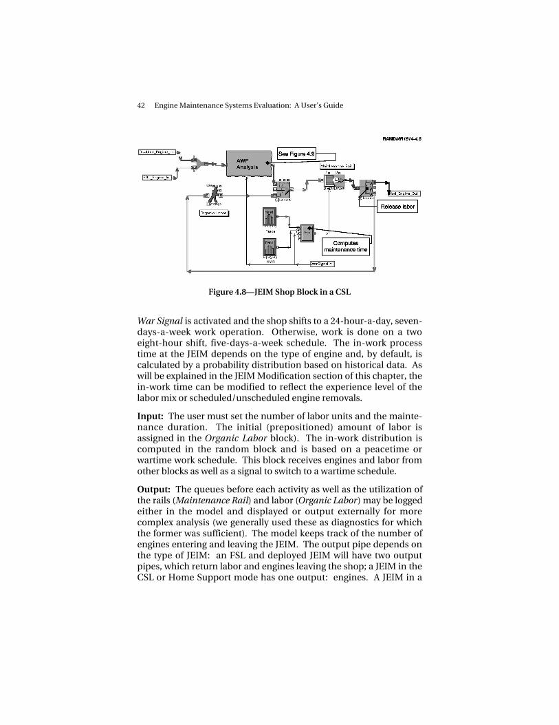
42 Engine Maintenance Systems Evaluation: A User’s Guide
Figure 4.8—JEIM Shop Block in a CSL
War Signal is activated and the shop shifts to a 24-hour-a-day, seven-days-a-week work operation. Otherwise, work is done on a twoeight-hour shift, five-days-a-week schedule. The in-work processtime at the JEIM depends on the type of engine and, by default, iscalculated by a probability distribution based on historical data. Aswill be explained in the JEIM Modification section of this chapter, thein-work time can be modified to reflect the experience level of thelabor mix or scheduled/unscheduled engine removals.
Input: The user must set the number of labor units and the mainte-nance duration. The initial (prepositioned) amount of labor isassigned in the Organic Labor block). The in-work distribution iscomputed in the random block and is based on a peacetime orwartime work schedule. This block receives engines and labor fromother blocks as well as a signal to switch to a wartime schedule.
Output: The queues before each activity as well as the utilization ofthe rails (Maintenance Rail) and labor (Organic Labor) may be loggedeither in the model and displayed or output externally for morecomplex analysis (we generally used these as diagnostics for whichthe former was sufficient). The model keeps track of the number ofengines entering and leaving the JEIM. The output pipe depends onthe type of JEIM: an FSL and deployed JEIM will have two outputpipes, which return labor and engines leaving the shop; a JEIM in theCSL or Home Support mode has one output: engines. A JEIM in a

EnMasse Library 43
unit will deploy engines with the engaged forces and may, if the sce-nario has an FSL, also deploy labor to the FSL.
AWP BLOCK
The AWP block (Figure 4.9) is contained within the JEIM Shop block.The AWP block adds a delay to the process to simulate the time spentawaiting parts for engine repair. Engines enter the block and, if therequired parts are not available, are routed to a holding cell asENMCS. In our study, the ENMCS calculation was based on histori-cal data, which was used to construct an empirical distribution ofwaiting times (see Figure A.3). An engine that is no longer ENMCSexits the block to be worked on by the labor units.
Input: The parameters in the ENMC-S Distribution and Delay Distri-bution can be edited by the user to modify the AWP probability dis-tribution. This block receives engine entities from other blocks.
Figure 4.9—AWP Block

44 Engine Maintenance Systems Evaluation: A User’s Guide
Output: As with the previous block, the user may observe theENMCS queue and the wait times for engines. This block pushesengine entities to other blocks.
MODIFIED JEIM BLOCK
As indicated earlier, the JEIM Shop block can easily be modified toaccommodate the experience level of the labor pool or the status ofthe engines (e.g., if removed because of scheduled or unscheduledmaintenance). Figure 4.10 depicts a modified JEIM shop for an F-15base. The labor pool consists of personnel at the base and returninglabor from an engagement. The unit JEIM deploys personnel to thefield of operations via the Labor_Deployed_Out block. An engage-ment is signaled by the LaborWarSignalIn block.
In the modified JEIM, the flow of the process is as follows. The baselabor is assigned a new attribute level known as an experience levelin the Experience Mix block (the returning labor has already beenassigned an experience attribute by this or other units). The laborpool therefore contains a mix of personnel with various levels ofwork experience (e.g., E3, E5). As with all other types of JEIM blocks,labor and NMC engines (after leaving the AWP block) are processedon a rail. In the modified block, however, the maintenance time is a
Figure 4.10—Modified JEIM Block

EnMasse Library 45
function of status of the engine (i.e., scheduled or unscheduledmaintenance) and the experience of the team dealing with the main-tenance (indicated by Engine Status and Labor Experience, respec-tively). The equation block (Processing Time) combines these twoattributes to create a delay in the process. The system keeps track ofthe number of engines arriving and the time of their arrival. At theend of this process, the engines are pushed to the next block and thelabor is released and returned to the labor pool.
Input: The user may define the experience mix and delay time bymodifying the Experience Mix block and the Processing Time block,respectively. This block receives engine entities and labor entitiesfrom other blocks.
Output: The output for this block is similar to that of the JEIM men-tioned earlier. The user may observe the queues before each activityas well as the utilization of the rails and labor. The model keeps trackof the number of engines entering and leaving the JEIM. The outputpipes for this type of JEIM are deployed labor and engines (or mod-ules, depending on the type of engine).
MODULE SHOP BLOCK
For such modular engines as the Pratt & Whitney F100 series, a Mod-ule Shop block must be added to the model. The engines leaving theJEIM Shop block enter this block and are immediately sorted intothree categories: modules sent to the depot, modules awaiting main-tenance because of parts, and modules ready for maintenance.
We have incorporated the parts delay for modules in the AWP Analy-sis block of the JEIM shop. (However, if the user wishes to representthe AWP explicitly for modules in the module shop, an AWP Analysisblock can be added immediately after the Module_Engine_Inpipeline.) Modules that require depot maintenance are pushedthrough the Depot Maintenance delay process (i.e., depot mainte-nance is not explicitly represented in the current model). Othermodules are assigned to labor when available and enter the ModRepair block (or Deployed Mod Repair for module shops that canreceive labor from other parts of the model). Figure 4.11 depicts a

46 Engine Maintenance Systems Evaluation: A User’s Guide
Figure 4.11—Module Shop Block
Mod Shop block at a deployed location (FSL or FOL) where pre-positioned labor is pooled with the deployed labor to form a LaborPool.
In the module shop, engines are separated into five modules to berepaired at five parallel work centers (see Figure 4.12). By default, thegearbox is sent directly to a depot; therefore, its block is more of aplaceholder. The other blocks pull in labor and modules for repair,with each having its own spare capacity and repair capability.
Figure 4.13 illustrates the shop capabilities for the core modulerepair shop. Arriving engine cores are divided into healthy parts thatare released immediately and those that require attention. The lattergroup is queued for repair. The repaired cores are pushed to the nextstage of maintenance. The other shops have similar structure.
Input: The Module Shop requires several inputs from the user: theinitial number of personnel (prepositioned labor), the capacity ofeach Mod Shop, and the spare level at each Mod Shop. The user mayalso want to modify the parameters in the Depot Distribution block,which determines the percentage of modules going to a depot, therepair time at each of the Mod Shops, and the distribution of healthymodules entering the depot shops.

EnMasse Library 47
Figure 4.12—Module Repair Block
Figure 4.13—Core Module Repair Shop Block

48 Engine Maintenance Systems Evaluation: A User’s Guide
Two pipelines enter the Module Shop block: labor enters throughMod_Labor_Deployed_In and engines through Module_Engine_In.The Module Repair block receives labor and modules from the Mod-ule Shop block.
Output: The Mod Shop block keeps track of queue length and sizefor the labor and the modules. The Mod Repair block keeps track ofthe shop’s utilization as well as the queue length and size for both thelabor and the modules. The Module Shop has two output pipelinesto the rest of the model: engine and labor unit output.
ASSEMBLY/TEST CELL BLOCK
The final block for the engine maintenance is the Assembly/Test Cellblock. In this block, engines are queued for final assembly, the testcell, and final inspection. As shown in Figure 4.14, this blockincludes several delays:7 for the final assembly, the “hush house”(the test cell stand), the final inspection, and the rerouting of theengines to their appropriate units or FOLs.8 The flow is as follows:modules are assembled (about one to two days) and then queued forthe hush house. The majority of the engines require about one dayof delay, but a small portion may take up to two days. Finally, theengines are inspected and returned to the appropriate bases.
Input: This block receives engine entities from another block, usu-ally the JEIM or Mod Shop block. The user must set the test cellcapacity by modifying the Test Cell block. The user may also modifythe delays for each of the processes.
Output: The main analytic outputs from this block are the queuesbefore the test cell and the utilization of the test cell (we simplyrecovered summary statistics from the block). The model also keepstrack of the number of engines served and the utilization of theassembly and final inspection blocks. The output pipeline dependson the number of bases or FOLs. In Figure 4.14, we have depicted ascenario with four FOLs.
______________ 7These delays were based on data analysis or on interviews with JEIM personnel.8Figure 4.14 depicts a scenario with two F-16 and two F-15 FOLs.

EnMasse Library 49
Figure 4.14—Assembly and Test Cell Block
SPARES ANALYSIS BLOCK
The Spares Analysis block, housed in an FOL or base block, receivesFMC engines from the Assembly/Test Cell block. NMC aircraft fromthe Flightline block are also sent to this block where they are strippedof some of their attributes and queued for serviceable engines.
Engines come to the Spares Analysis block from various sourcesdepending on the Mission Design Series (MDS) and the type ofspares analysis (i.e., FOL or unit). Figure 4.15 depicts a spares analy-sis block for an F-15 FOL (see Figure A.6 for a sample output). Ser-viceable engines arrive at the block from the Assembly/Test Cell block(Repaired_Engine_In) while cannibalized engines come from aircraftwith only one inoperable engine (Canned_Engine_In) and fromdeployed engines (Spares_Engine_In). Aircraft with holes are joinedwith the appropriate number of engines (i.e., depending on theMDS) to form FMC aircraft and then sent to the next block. The end-of-war signal (EOW_In) indicates when the deployed engines are tobe returned to their original bases.
There are two different types of Spares Analysis blocks, depending onwhether a deployed location or a base is used. The deployed locationis depicted in Figure 4.16, where, after the conflict, WREs arereturned to the home bases. Figure 4.17 depicts a block for an F-15base where WREs are instead deployed to various FOLs. In thisblock, a Spare Engine block has replaced the “SpareEngineIn” inputto account for the possibility that units might have their own reserveserviceable spares. In addition, because it is the start of war that sig-nals the deployment of the WREs for units, the EOW_In and

50 Engine Maintenance Systems Evaluation: A User’s Guide
Figure 4.15—Spares Analysis Block at an FOL
Figure 4.16—Spares Analysis Block at an F-15 Base
Deployed_Engine_Return_Out blocks have been replaced with aSpare Engines Deployment block, which keeps track of the number ofengines deployed and the date they are deployed (see Figure 4.17).Finally, because the units receive engines from deployed locations(“Engines Deployed” note), this block has an additional pipeline toreceive the returning engines from the FOL.
Input: For Spares Analysis at bases (Figure 4.16), the user must enterthe initial number of spares, the number of WREs (i.e., engines to bedeployed), and the day of deployment (Spare Engines Deploymentblock). The Spare Engines Deployment block requires two inputs

EnMasse Library 51
Figure 4.17—Spare Engines Deployment Block
from the user: the number engines to deploy (WRE) and the day theyshould start deploying. The Spares Analysis block for the FOL doesnot require any specific user inputs.
Output: Several outputs are produced by both types of blocks. Thereare two output pipelines, independent of the type of the block: FMCaircraft and the engine entity output. These return engines for theFOL block and deploy engines for the unit block. Additionally, themodel keeps track of daily spare levels, the arrival time of aircraftwith holes and serviceable engines, the queue length and time foraircraft with holes, and the length of time an engine is tagged asNMC.
TRANSPORTATION BLOCK
One of the main features of our model is the explicit representationof transportation, both for intertheater and intratheater. This blockconsists of a pool of vehicles (ground or air) and a one-way trans-portation time. Figure 4.18 illustrates the transportation route forround-trip travel. Engines enter the block, where they are joinedwith vehicles (from the “Vehicle Free” stock, each of which has a dif-ferent capacity). At the end of the travel, vehicles and engines arereleased.

52 Engine Maintenance Systems Evaluation: A User’s Guide
Figure 4.18—Transportation Block
Input: The user must enter a value for the expected one-way traveltime (One-way Trip block), as well as the number of vehicles andtheir capacity. If the user requires a range of time or a location-dependent time, the One-Way Trip block must be replaced by eithera Random block or a block that can respond to location attributes.Engines and vehicles are pulled from other blocks.
Output: The model measures vehicle utilization as well as the queuelength and time for the engines. Engines and vehicles are pushed toother blocks.
RESOURCE COMPUTATIONS BLOCK
The Resource Computations block keeps track of the deployment oflabor and aircraft. The Deployment Day block, a user input, indicatesthe start of the deployment for labor and aircraft (see Figure 4.19).
The Deployment Delay (Labor) block is provided to capture theabsence that some engine personnel not deployed with the fighteraircraft. The Deployment Calculation blocks produce a binary signalindicating whether the desired number of aircraft or labor has beensatisfied (see Figure 4.20). The deployment date (including anydelay) is compared with the current date (system clock) and on thedesired day the Deployment_Signal_Out block is activated, telling thereceiving block to release aircraft or support personnel. The aircraftand labor are passed through this block, generically identified as
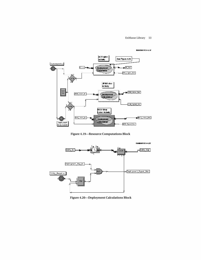
EnMasse Library 53
Figure 4.19—Resource Computations Block
Figure 4.20—Deployment Calculations Block

54 Engine Maintenance Systems Evaluation: A User’s Guide
Entity_In, and their count is compared to the desired number,Entity_Required. As soon as the desired number is reached, theDeployment_Signal_Out is deactivated. This, of course, does notindicate the end of the conflict but rather the completion of thedeployment.
Input: The user must input the day of deployment, possible delay inlabor deployment, and number of aircraft or labor required(Deployment Calculations block). Labor and aircraft are pulled fromother blocks.
Output: The user may observe the number of entities going throughthe Deployment Calculations block, but no analysis tool is in thisblock. Labor and aircraft signals and labor and aircraft entity are theoutputs for this block.
FOL BLOCK
The final block in the library is the FOL block, which receives aircraftfrom other bases and holds them until the end of an operation(Figure 4.21). This block is similar to those found in units in terms ofstructure but lacks any organic resource. The aircraft are deployed tothis block from other units, based on the numbers from the ResourceComputation block. They are queued until the E-Time signals theoperation, at which time they are pushed to the FOL Sortie Calcula-tion block, Flightline block, and the Spare Engines Analysis block.The Reconstitution block signals the return of the aircraft to theiroriginal bases. The “Return Complete” equation does not signal theend-of-war until all the aircraft are returned. At that time, it activatesthe return signal for the spares and personnel (EndOfWarOut signal).
Input: This model requires two dates from the user: the start of thewar (E-Time block) and the end of the conflict (Reconstitution block).Three input pipelines are connected to this block: aircraft deployedto the FOL (ACDeployedIn), spare engines sent to the FOL(DeployedEngineIn), and engines transported back from an FSL(FSLEngineIn).
Output: No analysis tool has been designed for this block. However,the user may observe the number of aircraft moving in and out of

EnMasse Library 55
Figure 4.21—FOL Block
other blocks. There are three output pipelines: the deployed aircraftreturning to their home base (ACReturnHomeOut), engines shippedto an FSL for repair (EngineFSLOut), and engines sent back to homebases after the conflict (DeployedEngineOut).

57
Chapter Five
CONCLUSIONS AND RECOMMENDATIONS
Given the nature of this report as a technical guide to the EnMassesimulation model, we again invite readers to refer to MR-1431-AF,Supporting Expeditionary Aerospace Forces: Alternatives for JetEngine Intermediate Maintenance, for the detailed analysis ofengine maintenance option policies and its resulting conclusions.We can, however, make certain conclusions and recommendationsregarding building a model using such GUI-based software asExtend.
A number of simulation models treat repair systems and have beenused for analyses similar to ours, the most notable of which is Dyna-METRIC, which was developed by RAND in the 1980s and usedextensively in various versions for a number of studies during the1980s and early 1990s. However, even the most recent versions ofDynaMETRIC do not satisfy the requirements outlined above. Theydo not track individual units with specific properties and do not havemuch detail in their representation of transportation. Further, theyare written in FORTRAN and difficult to modify internally to handlesome of these potential extensions.
Many of these drawbacks are absent in current GUI-simulationpackages. These packages, drawing on progress in programminglanguages, user interfaces, and hardware capabilities, make it possi-ble to quickly design, write, and use simulations whose complexityand detail would have been impossible with the computingresources available only a decade ago.
Building EnMasse using Extend blocks allowed us to identify indi-vidual engines and aircraft and capture detailed information about

58 Engine Maintenance Systems Evaluation: A User’s Guide
their status and progress in events ranging from flying sorties tomaintenance. Crucial management decisions in engine repair arebased on these characteristics, and EnMasse allows decisionmakersto evaluate potential alternative maintenance policies, such asreliability-centered maintenance.
EnMasse is flexible enough to be used for further analysis in futureexpanded studies of engine repair that can incorporate other impor-tant characteristics, such as the management of engine deploymentand repair based on the time characteristics of individual engines,the effects of engine demographics and different management deci-sions on JEIM and depot workload, more detailed representations ofrepair modes based on whether an engine removal is scheduled orunscheduled, and transportation policies. With EnMasse, theseextensions can be easily and naturally added in the future.
Extend (and ultimately EnMasse) is somewhat limited in terms ofinput and output generation. Although we have centralized most ofthe input parameters in one place and Extend allows writing of out-put to external files, further work may be needed to make the modeleasier to use. A centralized external database where all possibleinput parameters could be read would greatly enhance EnMasse andallow for a better parametric analysis of the system. Although thecurrent version of Extend software allows for basic sensitivity analy-sis, this feature is not flexible enough and will force additional“coding” for certain analyses of the engine maintenance system.
59
Appendix A
A SAMPLE RUN
In this appendix, we present some of the input and output parame-ters used in our analysis. We illustrate these parameters by runningan FSL scenario for the F100-229 engines.
MODEL SETUP
This model has two F-16 bases with 18 Primary Aircraft Authorized(PAA) each and two F-15 bases with 18 and 48 PAA. The utilizationrates for the F-16s and F-15s are set at 19 and 18, respectively. Wedeploy two-thirds of the aircraft to two single–Mission Design Series(MDS) forward operating locations (FOLs) with a single forward sup-port location (FSL) serving both FOLs. The war starts on day 365 ofthe simulation with 10 days of surge and 90 days of sustained flying.The simulation terminates on day 730. Engines are removed at therate of 3.5 per 1,000 flying hours for unscheduled engine removal(UER) and 1.5 per 1,000 flying hours for scheduled engine removal.We run the model for two simulated years.
Three rail teams are assigned to each F-16 base and the smaller F-15base, and seven rail teams are assigned to the larger F-15 base. Thelarger F-15 base deploys three of its rail teams and the others deployone each. Furthermore, two rail teams from other units augment theFSL, for a total of eight rail teams at the forward maintenance shop.
The current spares level and the war reserve engine (WRE) level areshown in Table A.1. Each unit has a single test cell and the FSL hastwo test cells.
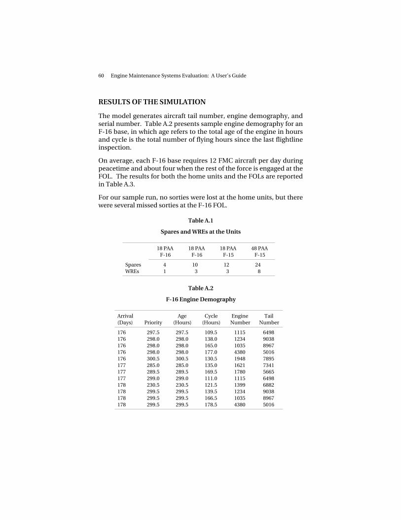
60 Engine Maintenance Systems Evaluation: A User’s Guide
RESULTS OF THE SIMULATION
The model generates aircraft tail number, engine demography, andserial number. Table A.2 presents sample engine demography for anF-16 base, in which age refers to the total age of the engine in hoursand cycle is the total number of flying hours since the last flightlineinspection.
On average, each F-16 base requires 12 FMC aircraft per day duringpeacetime and about four when the rest of the force is engaged at theFOL. The results for both the home units and the FOLs are reportedin Table A.3.
For our sample run, no sorties were lost at the home units, but therewere several missed sorties at the F-16 FOL.
Table A.1
Spares and WREs at the Units
18 PAAF-16
18 PAAF-16
18 PAAF-15
48 PAAF-15
Spares 4 10 12 24WREs 1 3 3 8
Table A.2
F-16 Engine Demography
Arrival(Days) Priority
Age(Hours)
Cycle(Hours)
EngineNumber
TailNumber
176 297.5 297.5 109.5 1115 6498176 298.0 298.0 138.0 1234 9038176 298.0 298.0 165.0 1035 8967176 298.0 298.0 177.0 4380 5016176 300.5 300.5 130.5 1948 7895177 285.0 285.0 135.0 1621 7341177 289.5 289.5 169.5 1780 5665177 299.0 299.0 111.0 1115 6498178 230.5 230.5 121.5 1399 6882178 299.5 299.5 139.5 1234 9038178 299.5 299.5 166.5 1035 8967178 299.5 299.5 178.5 4380 5016

A Sample Run 61
Figure A.1 illustrates two different simulation runs1 for this FOLshowing as high as 17 percent sortie loss (or about eight missed sor-ties out of 44) on day 374 (nine days into the conflict).
Table A.3
Aircraft Requirements at the Units andthe FOLs
F-16 F-15
Units 24, 8 40, 14FOLs 23, 12 35, 22
NOTE: Unit numbers are peacetime aircraft require-ments and aircraft requirements while the rest of theforce is engaged. FOL numbers are surge and sus-tained aircraft requirements.
RANDMR1614-A.1
Per
cent
age
of s
ortie
s m
isse
d
16
14
12
10
8
6
4
2
0908070605040
Days
3020100 100
18
Figure A.1—Percentage of Missed Sorties at the F-16 FOL
______________ 1The data are generated by the Sortie Shortfall block (see Figure 4.6).

62 Engine Maintenance Systems Evaluation: A User’s Guide
The JEIM Shop
The JEIM shop with its eight rail teams maintained an average of 35scheduled and 135 unscheduled engines during the conflict, with 41engines incurring an additional average delay of about 9.6 daysstemming from engine not mission capable because of supply(ENMCS).2 Figure A.2 illustrates the daily number of engines at theJEIM shop during this period.
Figure A.3 illustrates the distribution of ENMCS delays per engineduring the conflict,3 where the engaged forces are given priority inthe allocation of parts. Cumulatively, about 30 percent of all enginesare delayed because of the lack of appropriate parts, including mod-ules. As the figure indicates, the majority of engines are in ENMCS
RANDMR1614-A.2
Eng
ines
8
7
6
5
4
3
2
1
0908070605040
Days
3020100 100
9
Figure A.2—Daily Number of Engines at the JEIM Shop
______________ 2This figure is produced from the JEIM Shop block (see Figure 4.8).3Data are from the random number generator (Rand) in the AWP block (see Figure4.9).
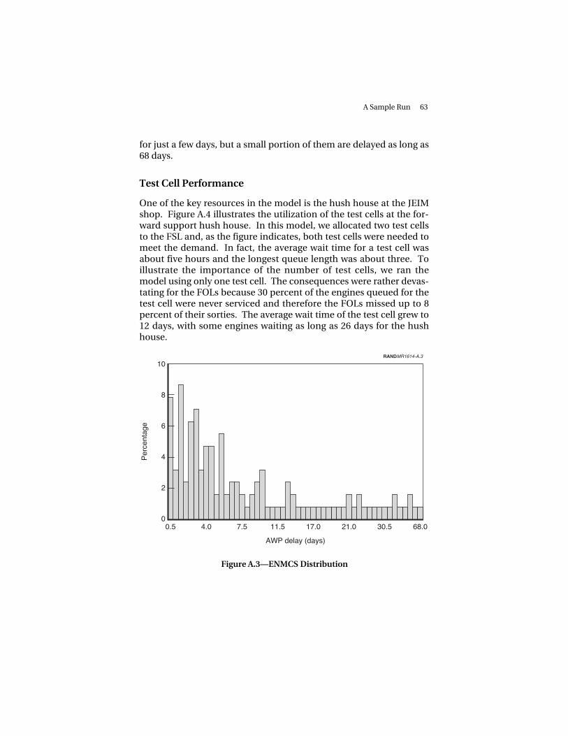
A Sample Run 63
for just a few days, but a small portion of them are delayed as long as68 days.
Test Cell Performance
One of the key resources in the model is the hush house at the JEIMshop. Figure A.4 illustrates the utilization of the test cells at the for-ward support hush house. In this model, we allocated two test cellsto the FSL and, as the figure indicates, both test cells were needed tomeet the demand. In fact, the average wait time for a test cell wasabout five hours and the longest queue length was about three. Toillustrate the importance of the number of test cells, we ran themodel using only one test cell. The consequences were rather devas-tating for the FOLs because 30 percent of the engines queued for thetest cell were never serviced and therefore the FOLs missed up to 8percent of their sorties. The average wait time of the test cell grew to12 days, with some engines waiting as long as 26 days for the hushhouse.
RANDMR1614-A.3
Per
cent
age
8�
6�
4�
2�
068.030.5�21.0�17.0�
AWP delay (days)
11.5�7.5�4.0�0.5
10�
Figure A.3—ENMCS Distribution

64 Engine Maintenance Systems Evaluation: A User’s Guide
Spare Engines Analysis
One of the key performance measures is the availability of spares atthe operating locations. Figure A.5 illustrates the typical dynamics ofserviceable spares at a single base.4 Aircraft quickly absorb the initialnumber of spares (i.e., spares allocated to the base at the beginningof the simulation) in the first few weeks, followed by a series ofrecoveries and losses. At the start of the conflict (period highlightedstarting at day 360), the number of spares dramatically drops asengines are deployed to forward locations. However, after the con-flict, a quick but small recovery occurs, followed by a series ofrecoveries and losses.
At the FOLs, the dynamics are somewhat different because the FSLrequires only a few days to become fully operational and the numberand duration of the sorties increase significantly. Figure A.6 illus-trates the daily serviceable spares at the F-15 FOL with the standard
RANDMR1614-A.4
Per
cent
age
of te
st c
ell u
tiliz
atio
n
80
70
60
50
40
30
20
10
09�8�7�6�5�4�
Weeks
3�2�1� 13�12�11�10� 14�
90
Figure A.4—Weekly Test Cell Utilization at the FSL
______________ 4Data are from the Spares Analysis block of an F-15 base (see Figure 4.16).

A Sample Run 65
RANDMR1614-A.5S
ervi
ceab
le s
pare
s
10
8
6
4
2
0540� 600�480�420�360�300�240�
Days
180�120600 660�
12
Figure A.5—Serviceable Spares at an F-15 Base
RANDMR1614-A.6
Ser
vice
able
spa
res
20
10
0
–10
–20
–3090�80�70�60�50�40�
Days
30�20�10�0 100
30
Standard WRE
All spares
Figure A.6—Serviceable Spares at the F-15 FOL

66 Engine Maintenance Systems Evaluation: A User’s Guide
WRE and the deployment of all available spares.5 It is not surprisingthat the increase in the number of initial spares has improved thehealth of the spare levels throughout the conflict. It should be noted,however, that an increase in the number of rail teams beyond thecurrent level would not improve the spares levels.6
______________ 5Data are from the Spares Analysis block of an F-15 FOL (see Figure 4.16).6There is a diminishing return for a marginal increase in the number of rail teams.The current rail team allocation is optimal for this FSL.

67
Appendix B
GLOSSARY OF EnMasse FIGURES AND ICONS
This appendix is a list of EnMasse blocks as they appear in thelibrary. We start with the most basic blocks and build toward theuppermost hierarchy of the EnMasse library. Most of the substantiveblocks from EnMasse have been discussed in detail in the text, and sodetailed input and output information is not repeated. For those notdiscussed, their function, the discussion of the other blocks, and thestructure of the real-world repair system should suffice to identifyinputs and outputs.
EnMasse BASIC BLOCKS
This section (Figures B.1 through B.12) lists the most basic blocks ofthe EnMasse library. Note that some of the less-common Extendblocks may be used.

68 Engine Maintenance Systems Evaluation: A User’s Guide
Figure B.1—Aircraft Engine Selection
Figure B.2—Sortie Shortfall Block
Figure B.3—Flight Sorties Block

Glossary of EnMasse Figures and Icons 69
Figure B.4—Flightline Inspection Block
Figure B.5—Assembly and Test Cell Block
Figure B.6—AWP Block

70 Engine Maintenance Systems Evaluation: A User’s Guide
Figure B.7—Individual Module Repair
Figure B.8—Labor Reconstitution Block

Glossary of EnMasse Figures and Icons 71
Figure B.9—Deployment Calculation Block
B.10—Transportation Block

72 Engine Maintenance Systems Evaluation: A User’s Guide
Figure B.11—Reset Attribute Block
Figure B.12—Spare Engines (WRE) Deployment Block
HIGHER-LEVEL BLOCKS
In this section (Figures B.13 through B.23), we present the next levelof the hierarchy by combining the basic blocks of the EnMasselibrary.

Glossary of EnMasse Figures and Icons 73
Figure B.13—JEIM Block at a Unit
Figure B.14—JEIM Block in a Deployed Location (FSL or Deployed JEIM)

74 Engine Maintenance Systems Evaluation: A User’s Guide
Figure B.15—JEIM Supporting Training and Deployed Units Block(CSL and Home Support)

Glossary of EnMasse Figures and Icons 75
Figure B.16—Module Repair Block

76 Engine Maintenance Systems Evaluation: A User’s Guide
Figure B.17—Resource Computation Block
Figure B.18—Spare Engines Analysis Block
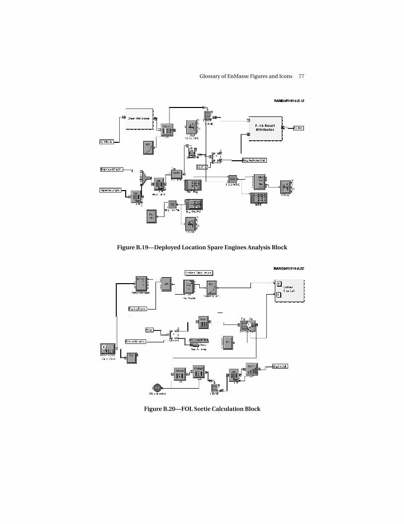
Glossary of EnMasse Figures and Icons 77
Figure B.19—Deployed Location Spare Engines Analysis Block
Figure B.20—FOL Sortie Calculation Block

78 Engine Maintenance Systems Evaluation: A User’s Guide
Figure B.21—Module Shop Block at the Units
Figure B.22—Deployed Module Shop Block (FSL, Deployed JEIM)

Glossary of EnMasse Figures and Icons 79
UPPER-LEVEL BLOCKS
This section (Figures B.24 through B.27) will cover the rest of theblocks in the EnMasse library. At the next level of the hierarchy, wecan represent bases, FOLs, FSLs, and CSLs.
Figure B.23—Module Shops Supporting Training and Deployed Units(CSL, Home Support)
Figure B.24—Engine Maintenance at an FSL or an FOL

80 Engine Maintenance Systems Evaluation: A User’s Guide
Figure B.25—Engine Maintenance at a CSL
Figure B.26—MDS-Based Unit Block

Glossary of EnMasse Figures and Icons 81
Figure B.27—FOL Block

83
BIBLIOGRAPHY
Amouzegar, Mahyar, Lionel A. Galway, and Amanda Geller, Support-ing Expeditionary Aerospace Forces: Alternatives for Jet EngineIntermediate Maintenance, Santa Monica, Calif.: RAND, MR-1431-AF, 2002.
Davis, Richard G., Immediate Reach, Immediate Power: The AirExpeditionary Force and American Power Projection in the PostCold War Era, Washington, D.C.: Air Force History and MuseumsProgram, 1998.
Feinberg, Amatzia, Hyman L. Shulman, Louis W. Miller, and RobertS. Tripp, Supporting Expeditionary Aerospace Forces: ExpandedAnalysis of LANTIRN Options, Santa Monica, Calif.: RAND, MR-1225-AF, 2001.
Galway, Lionel A., Robert S. Tripp, Timothy L. Ramey, and John G.Drew, Supporting Expeditionary Aerospace Forces: New AgileCombat Support Postures, Santa Monica, Calif.: RAND, MR-1075-AF, 2000.
Isaacson, Karen, and Patricia Boren, Dyna-METRIC Version 6: AnAdvanced Capability Assessment Model, Santa Monica, Calif.:RAND, R-4214-AF, 1993.
Killingsworth, Paul S., Lionel A. Galway, Eiichi Kamiya, BrianNichiporuk, Timothy L. Ramey, Robert S. Tripp, and James C.Wendt, Flexbasing: Achieving Global Presence for ExpeditionaryAerospace Forces, Santa Monica, Calif.: RAND, MR-1113-AF,2000.

84 Engine Maintenance Systems Evaluation: A User’s Guide
Peltz, Eric, Hyman L. Shulman, Robert S. Tripp, Timothy Ramey,Randy King, and John G. Drew, Supporting ExpeditionaryAerospace Forces: An Analysis of F-15 Avionics Options, SantaMonica, Calif.: RAND, MR-1174-AF, 2000.
Ryan, General Michael E., Evolving to an Expeditionary AerospaceForce, Commander’s NOTAM 98-4, Washington, D.C., July 28,1998.
Tripp, Robert S., Lionel A. Galway, Paul S. Killingsworth, Eric Peltz,Timothy L. Ramey, and John G. Drew, Supporting ExpeditionaryAerospace Forces: An Integrated Strategic Agile Combat SupportPlanning Framework, Santa Monica, Calif.: RAND, MR-1056-AF,1999.
Tripp, Robert S., Lionel A. Galway, Timothy L. Ramey, and MahyarAmouzegar, Supporting Expeditionary Aerospace Forces: A Con-cept for Evolving the Agile Combat Support/Mobility System of theFuture, Santa Monica, Calif.: RAND, MR-1179-AF, 2000.