aerophone+® system description - aerodata · aerophone+® system description aerodata® des-hw-954...
TRANSCRIPT

AeroPhone+® System Description
aerodata® DES-HW-954 Rev.0 1
AeroPhone+®
System Description
This document contains information proprietary to Aerodata AG. Any disclosure or use of this information or any reproduction of this document for other than the specific purpose for which it is intended is expressly prohibited except as Aerodata may otherwise agree in writing
AeroPhone+® System Description
aerodata® DES-HW-954 Rev.0 2
In case of questions please contact:
aerodata AG
Hermann–Blenk-Straße 34 - 36 D-38108 Braunschweig Germany Tel.: 0531 - 23 59 – 0 Fax: 0531 - 23 59 – 158 [email protected] www.aerodata.de
AeroPhone+® System Description
aerodata® DES-HW-954 Rev.0 3
Table of Contents 1 Overview 5
2 AeroPhone+® Satcom 7
2.1 Overview 7
2.2 AeroPhone+® Components and Variants 8
2.2.1 Satellite Transceiver Unit (AD-STUI) 9 2.2.1.1 Variants of the AD-STUI 10
2.2.2 Control panels 11 2.2.2.1 Multifunction Control Display Unit (MCDU) 11 2.2.2.2 Cockpit Dial Panel (CDP) 12 2.2.2.3 Handset wired (WHS) 12 2.2.2.4 Bluetooth Interface 13 2.2.2.5 Handset (Wi-Fi) 13
2.2.3 GPS Receiver 13
2.2.4 UMTS Version (AD-STUI-0210) 13
2.2.5 Wireless LAN Interface 13
2.3 Support operation in EUROPEAN Link2000+ airspace 14
3 Examples of Communication Solutions with AeroPhone+® 16
3.1 Communication Solution between Aircraft and Airline Operations Center 16
3.1.1 General 16
3.1.2 On-board solutions 17
3.1.3 Basic Communication 17
3.1.4 Full Cockpit Integration 18
3.1.5 Air Traffic Control Communication and full Cockpit Integration with Link2000+ capability 20
3.2 Fleet management 22
3.2.1 Fleet tracking and management with AeroDispatch 23
4 Technical Data 25
4.1 Certification 25

AeroPhone+® System Description
aerodata® DES-HW-954 Rev.0 4
4.2 Technical 25
4.3 Environmental Conditions according to DO-160 27
4.4 External interfaces of the STUI 28
4.4.1 Configuration variants 28
4.4.2 Connectors of the AD-STUI 29 4.4.2.1 Pictures of the AD-STUI-XXXX 30
5 Acronyms and Definitions 32
Table of Figures FIGURE 1: PRODUCT FAMILY AEROPHONE+® 5 FIGURE 2: COMPONENTS OVERVIEW 8 FIGURE 3: TABLE VARIANTS OF SATELLITE TRANSCEIVER UNITS 10 FIGURE 4: SAMPLE MCDU DISPLAY SUBMENU 11 FIGURE 5: EXAMPLE COCKPIT DIAL PANEL (CDP) 12 FIGURE 6: HANDSET WIRED 12 FIGURE 7: WLAN MODULE 14 FIGURE 8: BLOCK DIAGRAM LINK2000+ 15 FIGURE 9: COMMUNICATION BETWEEN AIRCRAFT AND AIRLINE OPERATIONS CENTER 17 FIGURE 10: COMMUNICATION SOLUTION FOR VOICE AND DATA (EXAMPLE) 18 FIGURE 11: BLOCK DIAGRAM COCKPIT SOLUTION WITH ACARS 19 FIGURE 12: COCKPIT INTEGRATION (EXAMPLE) 20 FIGURE 13: BLOCK DIAGRAM COCKPIT SOLUTION WITH LINK2000+ CAPABILITY 22 FIGURE 14: FLEET TRACKING WITH AEROPHONE+® (EXAMPLE) 23 FIGURE 15: AERODISPATCH GRAPHICAL USER INTERFACE (EXAMPLE) 24 FIGURE 16: AD-STUI-0100 (FRONT VIEW) 30 FIGURE 17: AD-STUI-0100 (BACK VIEW) 30 FIGURE 18: AD-STUI-0200/0210 (FRONT VIEW) 31 FIGURE 19: AD-STUI-0200/0210 (BACK VIEW) 31
AeroPhone+® System Description
aerodata® DES-HW-954 Rev.0 5
1 Overview
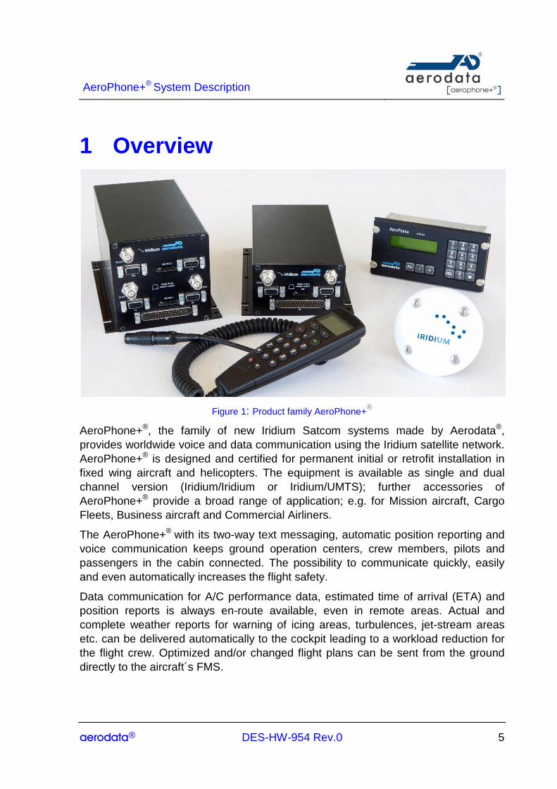
Figure 1: Product family AeroPhone+®
AeroPhone+®, the family of new Iridium Satcom systems made by Aerodata®, provides worldwide voice and data communication using the Iridium satellite network. AeroPhone+® is designed and certified for permanent initial or retrofit installation in fixed wing aircraft and helicopters. The equipment is available as single and dual channel version (Iridium/Iridium or Iridium/UMTS); further accessories of AeroPhone+® provide a broad range of application; e.g. for Mission aircraft, Cargo Fleets, Business aircraft and Commercial Airliners.
The AeroPhone+® with its two-way text messaging, automatic position reporting and voice communication keeps ground operation centers, crew members, pilots and passengers in the cabin connected. The possibility to communicate quickly, easily and even automatically increases the flight safety.
Data communication for A/C performance data, estimated time of arrival (ETA) and position reports is always en-route available, even in remote areas. Actual and complete weather reports for warning of icing areas, turbulences, jet-stream areas etc. can be delivered automatically to the cockpit leading to a workload reduction for the flight crew. Optimized and/or changed flight plans can be sent from the ground directly to the aircraft´s FMS.
AeroPhone+® System Description
aerodata® DES-HW-954 Rev.0 6
On ground, the AeroPhone+® equipped with GSM/UMTS in the second channel, enables low cost, high speed data transmission and voice communication through a standard ground network.
Reliable arrival time information through accurate and real-time position-reports, transfer of special events like take-off, cargo door sensors, landing, etc. leads to higher frequencies in aircraft operations and to a decrease of turn-around times in the logistics supply chain. Continuous tracking of all aircraft in a fleet and displaying on a map helps optimizing aircraft coordination and reviewing fleet activity.
Any data send over the IRIDIUM gateway can be received via e-mail by third party applications, e.g. fleet management based on ARINC®, SITA®, AeroDispatch and many others.
With AeroPhone+®, internet services like web browsing, e-mail, etc. are available worldwide for all crew members and passengers on laptops, handhelds and any other Wi-Fi accessory.
AeroPhone+® System Description
aerodata® DES-HW-954 Rev.0 7
2 AeroPhone+® Satcom
2.1 Overview All AeroPhone® versions provide at least one Iridium satellite channel which can be used for voice or data transmissions.
The enhanced capabilities and new features of AeroPhone+® include:
• Enhanced Voice and Data Communication;
• Increased Safety;
• Optimized Fleet Logistics;
• Operational Benefits and Cost Reduction.
These benefits are realized by
• World-wide Communication covering remote areas, e.g. polar and oceanic region;
• Single and Dual Channel Voice and Data Communication, Short Burst Data Service;
• Direct web link from aircraft to operator’s host;
• ARINC 429 Interfaces to FMS, CMU and MCDU for Logistics and ACARS Services;
• Tracking Option with
o integrated GPS;
o position data via ARINC 429;
o position data via RS232 (NMEA);
• Bluetooth and WLAN interfaces;
• Low system installation and operation cost for fixed wing aircraft and helicopters;
• Easy and flexible operation;
• ETSO-2C514 Approval.

AeroPhone+® System Description
aerodata® DES-HW-954 Rev.0 8
2.2 AeroPhone+® Components and Variants
Figure 2: Components Overview
The telecommunication system AeroPhone+® based on IRIDIUM is a single-box, single or dual channel system providing voice and data communication, which is certified according to ETSO-2C514.
The system is designed for initial and retrofit installation in fixed wing aircraft and helicopters. Due to the availability of different installation kits the system installation can be realized with minimum effort in a repair station during aircraft line maintenance. The AeroPhone+® components comprise:
• the satellite transceiver unit AD-STUI (central unit);
• the cockpit dial panel (AD-CDP);
• the IRIDIUM antenna, which is designed as patch antenna;
• an optional GPS antenna;
• an optional handset (wireless or wired);
• an optional headset (wireless);
• an optional WLAN interface.
With a weight of approximately 1.6 kg / 2.3 kg (single/dual channel transceiver including one dial panel and antenna) the system only adds negligible weight to helicopters or fixed-wing aircraft.
AeroPhone+® System Description
aerodata® DES-HW-954 Rev.0 9
The system can be connected directly to the primary intercom system of the aircraft. The cockpit dial panel or an interfaced MCDU enables the flight crew to control the system, sending messages and to place calls.
To use the AeroPhone+® for Direct Internet or Dial up Data Services, a laptop with optional software tools can be connected.
A handset for cabin access to the Iridium Network is available as an optional extension to the basic system to enable voice communication and messaging for flight crew, cabin crew or passengers.
2.2.1 Satellite Transceiver Unit (AD-STUI) The AeroPhone+® transceiver unit is housed in a single-box. It is compatible with the previous AeroPhone® system and allows a direct retrofit without the change of the installation. The main features of AeroPhone+® are:
• single and dual channel versions (Iridium; Iridium/Iridium; Iridium/UMTS);
• up to 200 phone book entries;
• aural and visual incoming call indication;
• connected directly to the aircraft intercom;
• interfaces:
o dual channel Intercom audio in/out;
o ARINC 429 (FMS, CMU, MCDU, FDR);
o RS-232/422 (data services, PC-interface);
o Ethernet;
o Bluetooth (data, headset, handset);
o internal GPS receiver;
o position reports e.g. for Fleet Management.
• SBD, SMS, e-mail, point to point connection;
• Options:
o WLAN (data, headset, handset);
o ACARS data formatting for Aeronautical Administrative Control;
AeroPhone+® System Description
aerodata® DES-HW-954 Rev.0 10
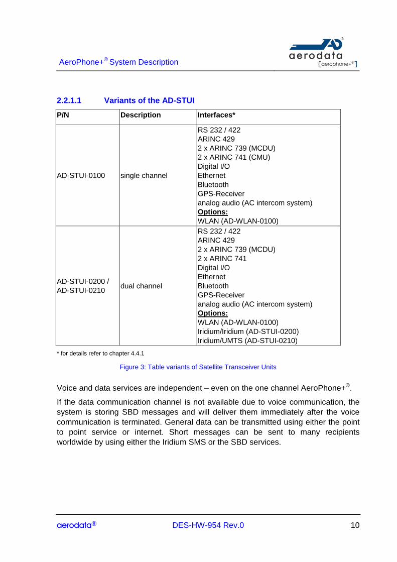
2.2.1.1 Variants of the AD-STUI
P/N Description Interfaces*
AD-STUI-0100 single channel
RS 232 / 422 ARINC 429 2 x ARINC 739 (MCDU) 2 x ARINC 741 (CMU) Digital I/O Ethernet Bluetooth GPS-Receiver analog audio (AC intercom system) Options: WLAN (AD-WLAN-0100)
AD-STUI-0200 / AD-STUI-0210 dual channel
RS 232 / 422 ARINC 429 2 x ARINC 739 (MCDU) 2 x ARINC 741 Digital I/O Ethernet Bluetooth GPS-Receiver analog audio (AC intercom system) Options: WLAN (AD-WLAN-0100) Iridium/Iridium (AD-STUI-0200) Iridium/UMTS (AD-STUI-0210)
* for details refer to chapter 4.4.1
Figure 3: Table variants of Satellite Transceiver Units
Voice and data services are independent – even on the one channel AeroPhone+®.
If the data communication channel is not available due to voice communication, the system is storing SBD messages and will deliver them immediately after the voice communication is terminated. General data can be transmitted using either the point to point service or internet. Short messages can be sent to many recipients worldwide by using either the Iridium SMS or the SBD services.
AeroPhone+® System Description
aerodata® DES-HW-954 Rev.0 11
2.2.2 Control panels
The AeroPhone+® system can be operated by a variety of different control panels and cockpit/cabin installations.
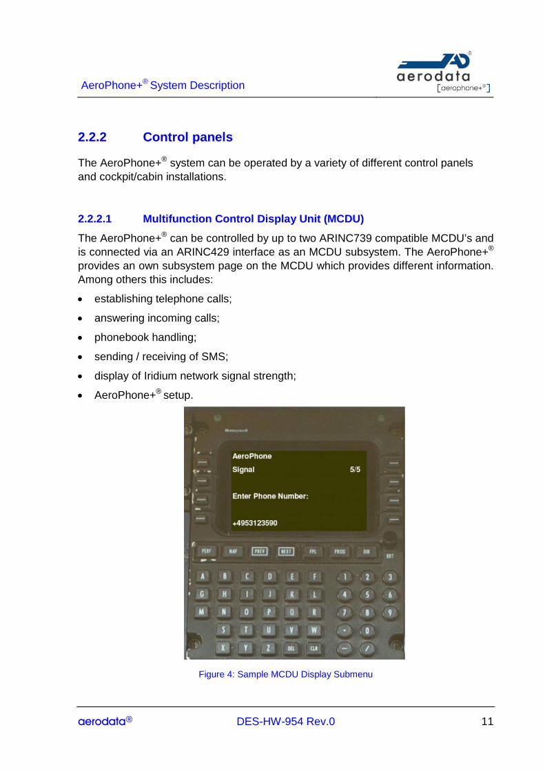
2.2.2.1 Multifunction Control Display Unit (MCDU)
The AeroPhone+® can be controlled by up to two ARINC739 compatible MCDU’s and is connected via an ARINC429 interface as an MCDU subsystem. The AeroPhone+® provides an own subsystem page on the MCDU which provides different information. Among others this includes:
• establishing telephone calls;
• answering incoming calls;
• phonebook handling;
• sending / receiving of SMS;
• display of Iridium network signal strength;
• AeroPhone+® setup.
Figure 4: Sample MCDU Display Submenu

AeroPhone+® System Description
aerodata® DES-HW-954 Rev.0 12
2.2.2.2 Cockpit Dial Panel (CDP)
The AD-CDP is the standard device for operating AeroPhone+® and consists of a LCD display of 2x16 characters, a keypad with 15 keys and a RS232 interface to the central unit. Display and keys are back lighted by green LEDs.
Telephone numbers, SMS and e-mails can be entered, dialled and sent. A telephone book with a capability of up to 200 entries is provided as well as a setup menu for the configuration and control of the system adjustment. Up to two Cockpit Dial Panels can be connected to one Satellite Transceiver Unit (STUI).
Figure 5: Example Cockpit Dial Panel (CDP)
2.2.2.3 Handset wired (WHS)
A wired handset for cabin access to the Iridium Network for voice communication is available. The AD-WHS consists of a LCD display of 2x16 characters, a Keypad with 20 keys and an interface to the central unit. Display and keys are back lighted.
Telephone numbers, SMS and e-mails can be entered, dialled and sent. A telephone book with a capability of up to 200 entries is provided as well as a setup menu for the configuration and control of the system adjustment.
Figure 6: Handset wired

AeroPhone+® System Description
aerodata® DES-HW-954 Rev.0 13
2.2.2.4 Bluetooth Interface
The AeroPhone+® provides a Bluetooth network for cabin access to the Iridium Network via Bluetooth for data transfer and voice communication with Hand- and Headsets.
2.2.2.5 Handset (Wi-Fi)
The AeroPhone+® can be controlled by a Wi-Fi handset if the optional WLAN-Module (AD-WLAN-0100) is connected to the Satellite Transceiver Unit.
2.2.3 GPS Receiver The AeroPhone+® features an integrated GPS receiver. Independent from the aircraft interfaces, position data can be sent for tracking and/or fleet managing via SMS, SBD or e-mail.
Optionally position data from cockpit equipment can be interfaced to the AeroPhone+® via RS232 (NMEA) or ARINC 429.
2.2.4 UMTS Version (AD-STUI-0210) The AeroPhone+® can be used for Iridium satellite communication and GSM/UMTS communication. By using the GSM/UMTS mode the data rate is increased while cost is reduced. Prescribed by the regulations GSM/UMTS mode is limited to ground operation only. While on ground AeroPhone+® uses the GSM/UMTS mode.
2.2.5 Wireless LAN Interface (AD-WLAN-0100) The AeroPhone+® can provide a WLAN network to connect a laptop or any other Wi-Fi accessory direct to the Internet or Dial Up Data Services within the cabin. The WLAN-Module (AD-WLAN-0100) is connected to the Satellite Transceiver Unit via Ethernet connection and is available as optional single-box.
Figure 7: WLAN Module

AeroPhone+® System Description
aerodata® DES-HW-954 Rev.0 14
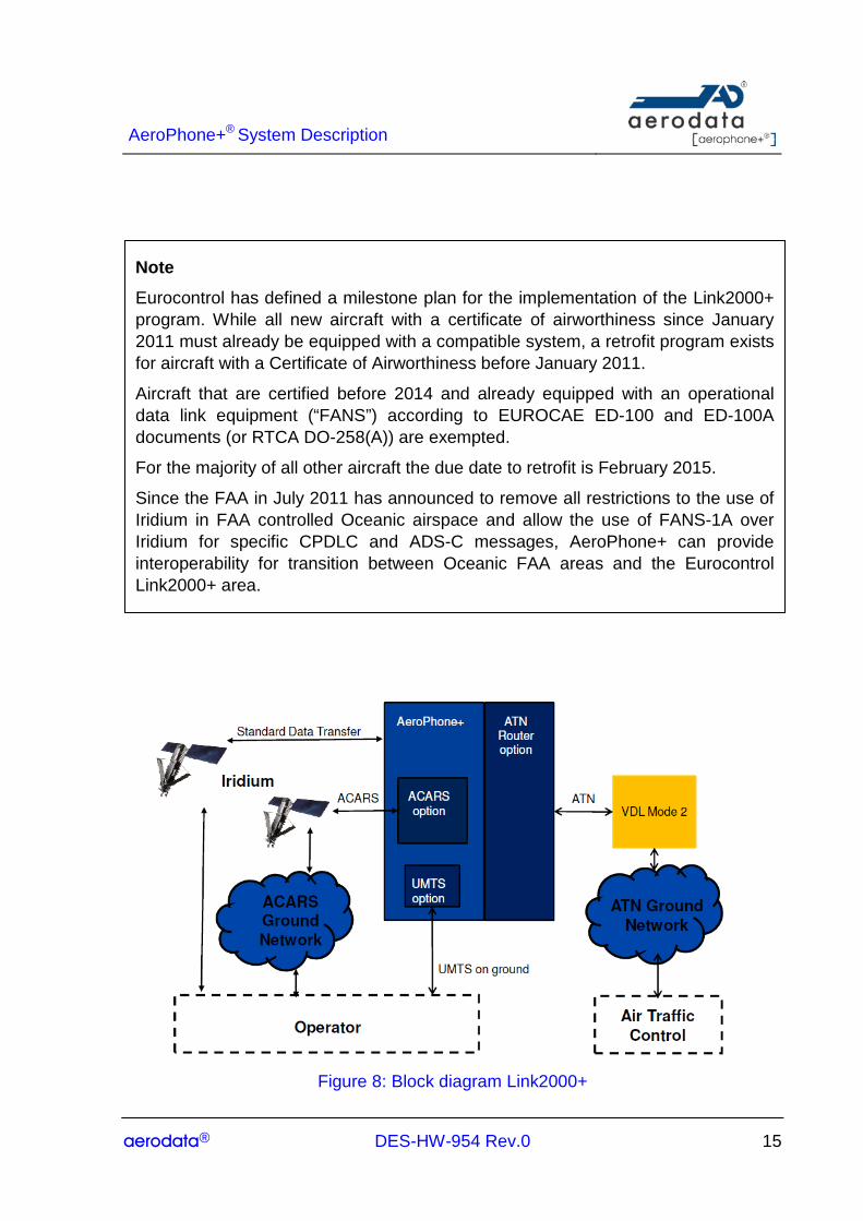
2.3 Support operation in EUROPEAN Link2000+ airspace The Eurocontrol Link2000+ concept requires aircraft operating IFR as General Air Traffic above Flight Level 285 to be equipped with an ATN certified data link system providing Controller Pilot Data Link Communication (CPDLC). Safety cases have shown that at present the only feasible system is the VDL Mode 2 data link.
As a future option, AeroPhone+® enables the use of Link2000+ by providing interfaces and techniques to comply with the following main requirements for a compatible aircraft system:
1. The aircraft must be equipped with a compatible Human Machine Interface. The human machine interface comprises a MCDU, a printer and an audible/visual alert system.
AeroPhone+® provides the interface to ARINC 739 compatible MCDU systems, printer and alert systems.
2. The aircraft must be equipped with an ATN compatible communication management unit for encoding and decoding of the safety related messages as CPDLC.
AeroPhone+® will provide the compatible router system that implements the message generation and decoding according to the required ATN CPDLC standards.
3. The aircraft must be equipped with a VHF Data Radio implementing VDL-2
AeroPhone+® will allow connecting ARINC 485 compatible VDL mode 2 data link radios to the internal router system to comply with the regulation.
AeroPhone+® will be the solution for retrofit. Retrofit users benefit from cost effective fleet message transfer using Iridium and in parallel enabling capability to the Link2000+ program.
AeroPhone+® System Description
aerodata® DES-HW-954 Rev.0 15
Figure 8: Block diagram Link2000+
Note
Eurocontrol has defined a milestone plan for the implementation of the Link2000+ program. While all new aircraft with a certificate of airworthiness since January 2011 must already be equipped with a compatible system, a retrofit program exists for aircraft with a Certificate of Airworthiness before January 2011.
Aircraft that are certified before 2014 and already equipped with an operational data link equipment (“FANS”) according to EUROCAE ED-100 and ED-100A documents (or RTCA DO-258(A)) are exempted.
For the majority of all other aircraft the due date to retrofit is February 2015.
Since the FAA in July 2011 has announced to remove all restrictions to the use of Iridium in FAA controlled Oceanic airspace and allow the use of FANS-1A over Iridium for specific CPDLC and ADS-C messages, AeroPhone+ can provide interoperability for transition between Oceanic FAA areas and the Eurocontrol Link2000+ area.
AeroPhone+® System Description
aerodata® DES-HW-954 Rev.0 16
3 Examples of Communication Solutions with AeroPhone+®
3.1 Communication Solution between Aircraft and Airline Operations Center
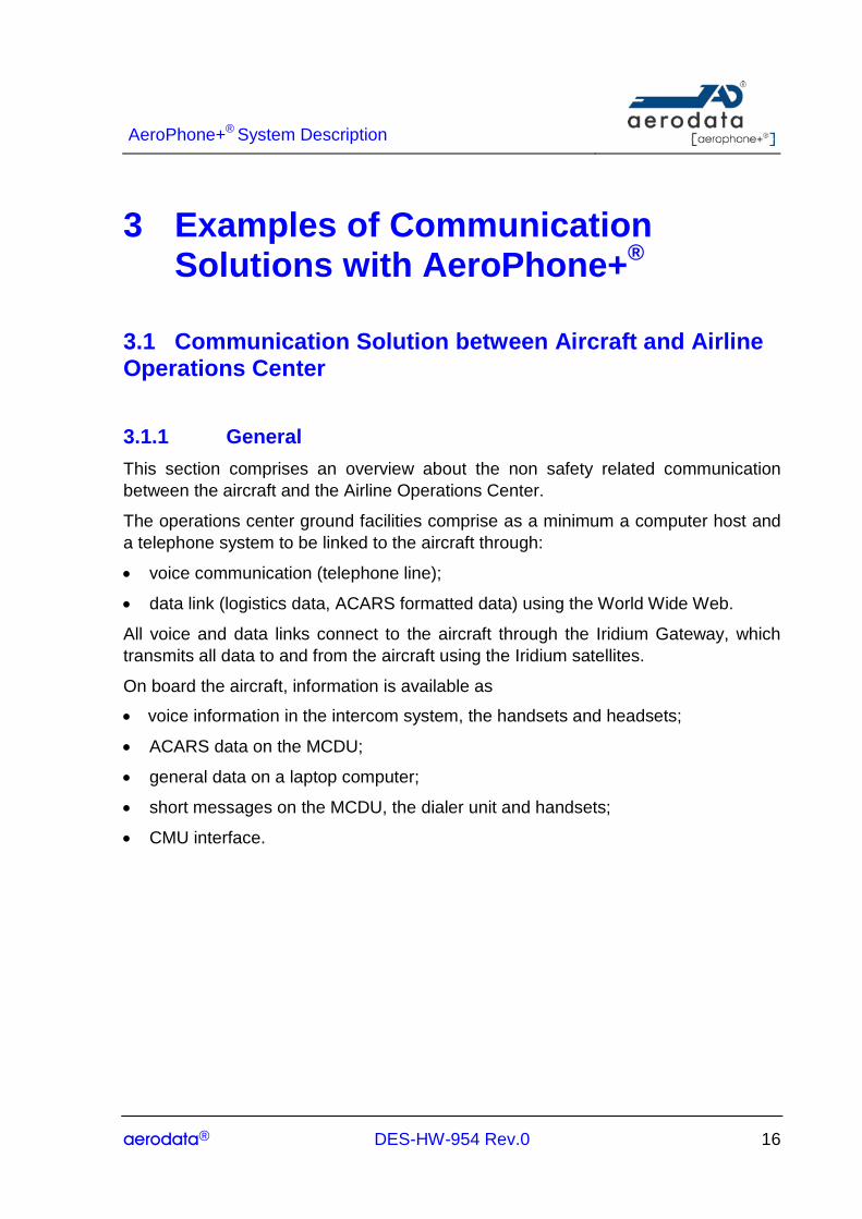
3.1.1 General This section comprises an overview about the non safety related communication between the aircraft and the Airline Operations Center.
The operations center ground facilities comprise as a minimum a computer host and a telephone system to be linked to the aircraft through:
• voice communication (telephone line);
• data link (logistics data, ACARS formatted data) using the World Wide Web.
All voice and data links connect to the aircraft through the Iridium Gateway, which transmits all data to and from the aircraft using the Iridium satellites.
On board the aircraft, information is available as
• voice information in the intercom system, the handsets and headsets;
• ACARS data on the MCDU;
• general data on a laptop computer;
• short messages on the MCDU, the dialer unit and handsets;
• CMU interface.
AeroPhone+® System Description
aerodata® DES-HW-954 Rev.0 17
Figure 9: Communication between Aircraft and Airline Operations Center
3.1.2 On-board solutions The overall communication solution as depicted above can be realized through various airborne implementations achieving various integration levels.
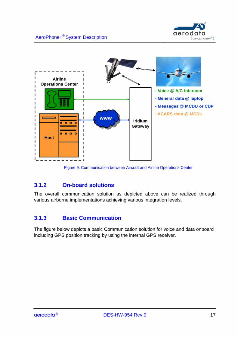
3.1.3 Basic Communication
The figure below depicts a basic Communication solution for voice and data onboard including GPS position tracking by using the internal GPS receiver.
- Voice @ A/C Intercom
- General data @ laptop
- Messages @ MCDU or CDP
- ACARS data @ MCDU
Host
Iridium Gateway
WWW
AirlineOperations Center
AeroPhone+® System Description
aerodata® DES-HW-954 Rev.0 18
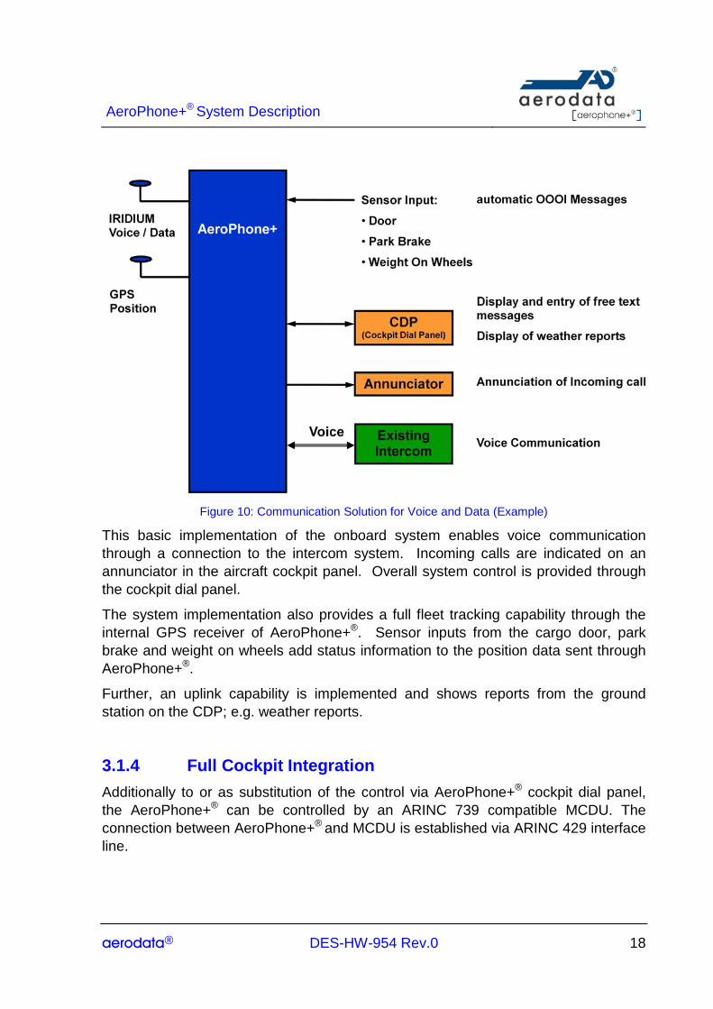
Figure 10: Communication Solution for Voice and Data (Example)
This basic implementation of the onboard system enables voice communication through a connection to the intercom system. Incoming calls are indicated on an annunciator in the aircraft cockpit panel. Overall system control is provided through the cockpit dial panel.
The system implementation also provides a full fleet tracking capability through the internal GPS receiver of AeroPhone+®. Sensor inputs from the cargo door, park brake and weight on wheels add status information to the position data sent through AeroPhone+®.
Further, an uplink capability is implemented and shows reports from the ground station on the CDP; e.g. weather reports.
3.1.4 Full Cockpit Integration Additionally to or as substitution of the control via AeroPhone+® cockpit dial panel, the AeroPhone+® can be controlled by an ARINC 739 compatible MCDU. The connection between AeroPhone+® and MCDU is established via ARINC 429 interface line.

AeroPhone+® System Description
aerodata® DES-HW-954 Rev.0 19
The transfer of ACARS data uses the current ACARS format for non safety communication (AAC). An interface to the FMS is included so that flight plans can be transferred to the FMS.
The AeroPhone+® connects itself on the MCDU as a subsystem using the ARINC 739 protocol. The AeroPhone+® provides an own subsystem page on the MCDU which provides the information and functionality of the AeroPhone+® CDP, which includes among others:
• establishing telephone calls;
• answering incoming calls;
• phonebook handling;
• sending / receiving of SMS;
• display of Iridium network signal strength;
• AeroPhone+® setup.
Figure 11: Block Diagram Cockpit Solution with ACARS
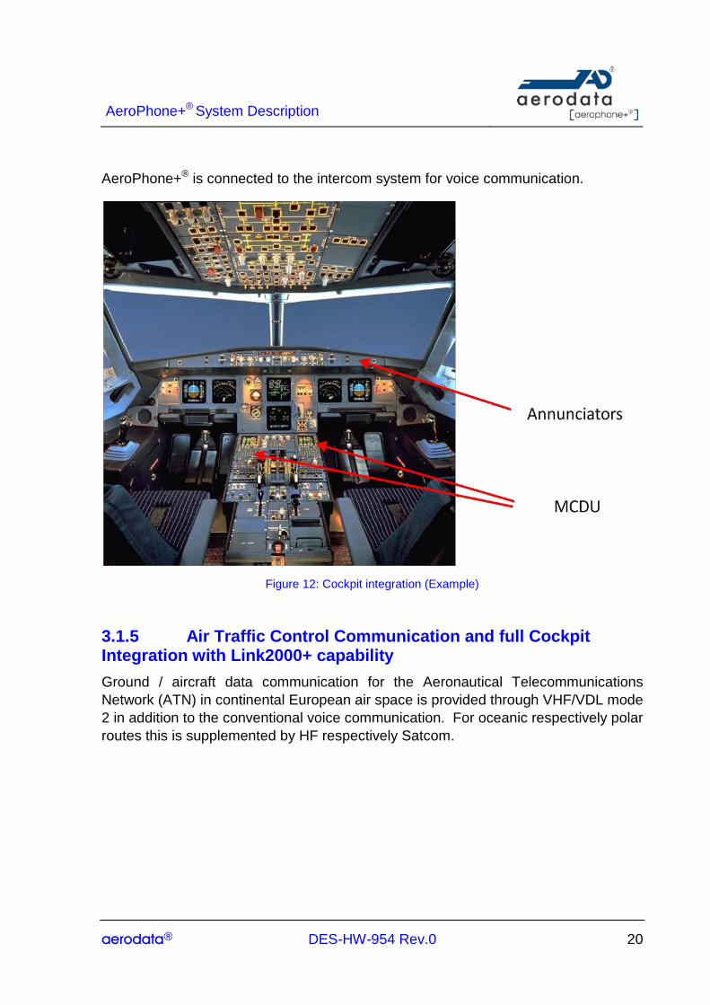
A typical cockpit layout of such an implementation is depicted in the figure below. Control of the AeroPhone+® is provided through the MCDU’s in the center pedestal of the cockpit. The MCDU’s will also show digital messages received through the AeroPhone+® and will allow the compilation of messages for transmission to the ground. Cockpit indicators alert the cockpit crew about received phone calls or digital messages.
AeroPhone+® System Description
aerodata® DES-HW-954 Rev.0 20
AeroPhone+® is connected to the intercom system for voice communication.
Figure 12: Cockpit integration (Example)
3.1.5 Air Traffic Control Communication and full Cockpit Integration with Link2000+ capability Ground / aircraft data communication for the Aeronautical Telecommunications Network (ATN) in continental European air space is provided through VHF/VDL mode 2 in addition to the conventional voice communication. For oceanic respectively polar routes this is supplemented by HF respectively Satcom.

AeroPhone+® System Description
aerodata® DES-HW-954 Rev.0 21
Ground-Aircraft Communication Concept (ACARS/ATN)
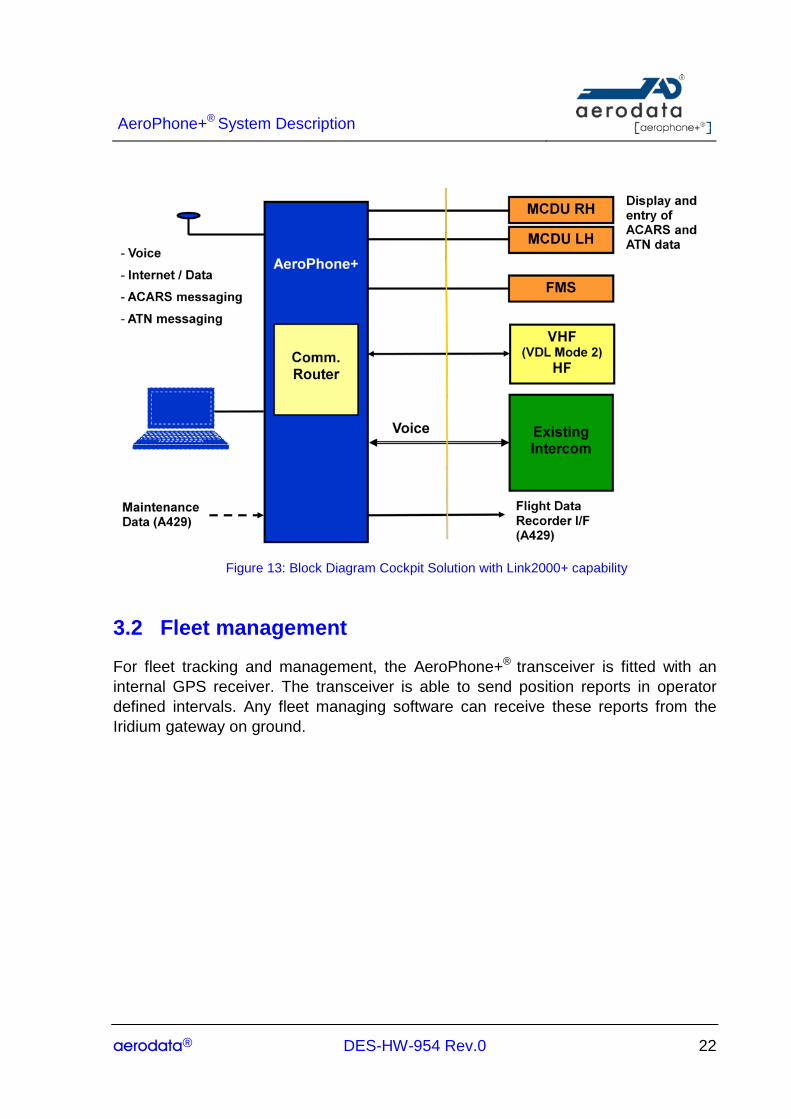
The onboard solution for air traffic control related functionality is shown in the figure below. The additional function used in the AeroPhone+® is a communication router which can select automatically the VDL mode 2 data link or the Iridium link depending on availability. In case that AeroPhone+® is used for air traffic control related functionalities, the system has to be connected to the flight data recorder to provide for the recording of digital air traffic control messages.
AeroPhone+® System Description
aerodata® DES-HW-954 Rev.0 22
Figure 13: Block Diagram Cockpit Solution with Link2000+ capability
3.2 Fleet management
For fleet tracking and management, the AeroPhone+® transceiver is fitted with an internal GPS receiver. The transceiver is able to send position reports in operator defined intervals. Any fleet managing software can receive these reports from the Iridium gateway on ground.
AeroPhone+® System Description
aerodata® DES-HW-954 Rev.0 23
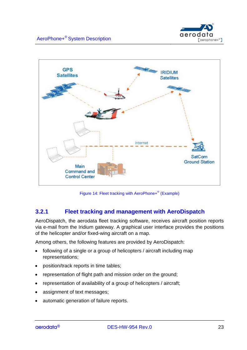
Figure 14: Fleet tracking with AeroPhone+® (Example)
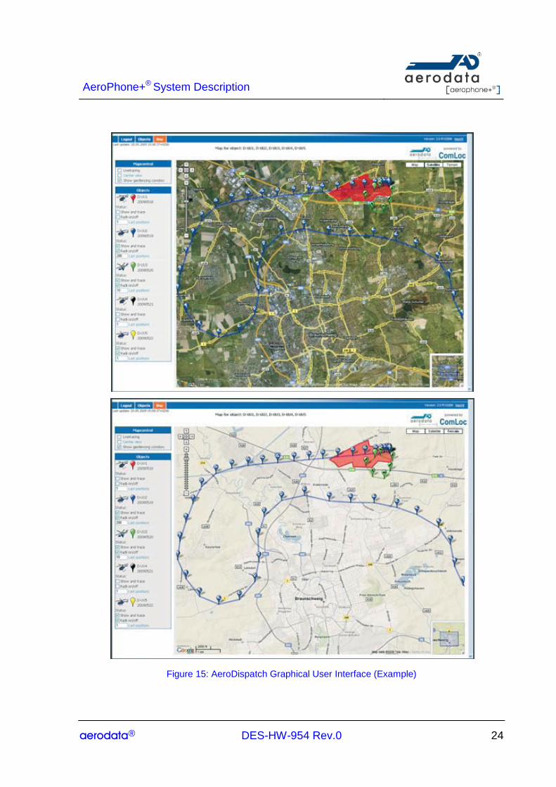
3.2.1 Fleet tracking and management with AeroDispatch AeroDispatch, the aerodata fleet tracking software, receives aircraft position reports via e-mail from the Iridium gateway. A graphical user interface provides the positions of the helicopter and/or fixed-wing aircraft on a map.
Among others, the following features are provided by AeroDispatch:
• following of a single or a group of helicopters / aircraft including map representations;
• position/track reports in time tables;
• representation of flight path and mission order on the ground;
• representation of availability of a group of helicopters / aircraft;
• assignment of text messages;
• automatic generation of failure reports.
AeroPhone+® System Description
aerodata® DES-HW-954 Rev.0 24
Figure 15: AeroDispatch Graphical User Interface (Example)

AeroPhone+® System Description
aerodata® DES-HW-954 Rev.0 25
4 Technical Data
4.1 Certification AeroPhone+® meets standard certification criteria for avionics equipment; in particular:
• Airworthiness Approval : ETSO-2C514
• Environmental Qualification: RTCA DO-160F / EUROCAE ED 14F
• Software Standards: RTCA DO-178B / EUROCAE ED12B
• Hardware Standards: RTCA DO-254 / EUROCAE ED80
In addition, the Declaration of Design and Performance for AeroPhone+® will include functionality not required in ETSO-2C514 thus making installation and use of these features simpler.
4.2 Technical • Data Transmission Rate (IRIDIUM):
o Point-to-point: up to 2400 baud
o Web access: up to 9600 baud
• Data Transmission Rate (GSM/UMTS):
o Point-to-point (Modem): up to 9600 kb/s
o Web access: up to 3,6 Mb/s download; 384 kb/s upload
• Frequency Range:
o 1616 – 1626.5 MHz, L-Band
o GSM/UMTS
2100 MHz, Band I
900 MHz, Band VIII

AeroPhone+® System Description
aerodata® DES-HW-954 Rev.0 26
• Electrical Specification:
o Voltage: 18 – 32V
o Average Power Consumption: < 1 A at 28V (single channel) < 2 A at 28V (dual channel)
• Environmental Specification for STUI and CDP:
o Temperature Range Storage: – 40°C … + 85° C Operation: – 20°C … + 60° C
o Humidity: 95%, non-condensing
• Environmental Specification Antenna:
o Operational/ Storage Temperature: - 55°C… + 85° C
• Mechanical Specification STUI:
o Housing(L x W x H): 221 x 130 x 66 mm (single channel) 239 x 130 x 106 mm (dual channel)
o Weight: 1.4 kg (single channel) 2.6 kg (dual channel)
• Mechanical Specification CDP:
o Housing (L x W x H): 76 x 146 x 50 mm (8 DZUS)
o Weight: 0.4 kg
• Mechanical Specification Antenna:
o Dim. (Height x Diameter): 17 x 90 mm
o Weight: 0.2 kg
• Mechanical Specification WLAN module:
o Housing (L x W x H): 200 x 105 x 39 mm
o Weight: 0.5 kg
AeroPhone+® System Description
aerodata® DES-HW-954 Rev.0 27
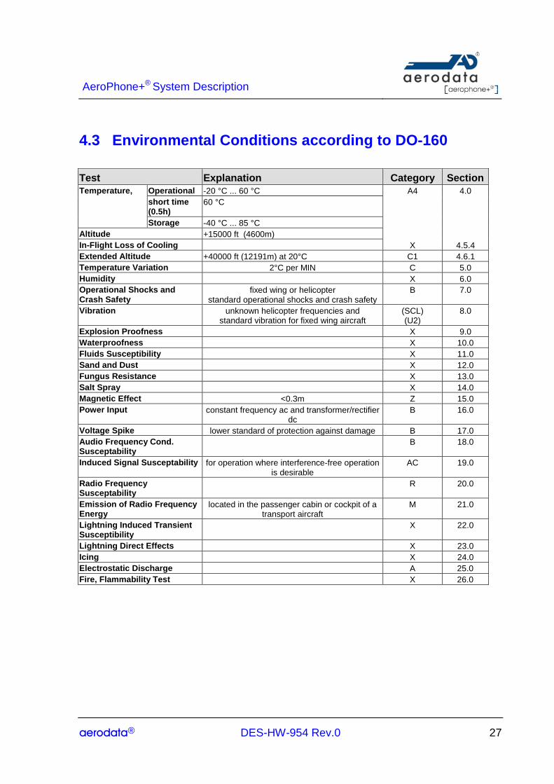
4.3 Environmental Conditions according to DO-160 Test Explanation Category Section Temperature, Operational -20 °C ... 60 °C A4 4.0 short time
(0.5h) 60 °C
Storage -40 °C ... 85 °C Altitude +15000 ft (4600m) In-Flight Loss of Cooling X 4.5.4 Extended Altitude +40000 ft (12191m) at 20°C C1 4.6.1 Temperature Variation 2°C per MIN C 5.0 Humidity X 6.0 Operational Shocks and Crash Safety
fixed wing or helicopter standard operational shocks and crash safety
B 7.0
Vibration unknown helicopter frequencies and standard vibration for fixed wing aircraft
(SCL) (U2)
8.0
Explosion Proofness X 9.0 Waterproofness X 10.0 Fluids Susceptibility X 11.0 Sand and Dust X 12.0 Fungus Resistance X 13.0 Salt Spray X 14.0 Magnetic Effect <0.3m Z 15.0 Power Input constant frequency ac and transformer/rectifier
dc B 16.0
Voltage Spike lower standard of protection against damage B 17.0 Audio Frequency Cond. Susceptability
B 18.0
Induced Signal Susceptability for operation where interference-free operation is desirable
AC 19.0
Radio Frequency Susceptability
R 20.0
Emission of Radio Frequency Energy
located in the passenger cabin or cockpit of a transport aircraft
M 21.0
Lightning Induced Transient Susceptibility
X 22.0
Lightning Direct Effects X 23.0 Icing X 24.0 Electrostatic Discharge A 25.0 Fire, Flammability Test X 26.0

AeroPhone+® System Description
aerodata® DES-HW-954 Rev.0 28
4.4 External interfaces of the STUI
4.4.1 Configuration variants AD-STUI-0100 AD-STUI-0200 Connector Power supply via 28V DC1 X X P2 IRIDIUM antenna (9522B ) 1 2 P3 GPS antenna 1 1 P5 Bluetooth antenna 2 2 P7 (Voice), P8
(Data) SIM card connector 1 2 - Audio Link (Analog Audio, PTT, MIC PWR)
2 2 P2
ARINC429 interface 4 6 P4(2),P11(2), P6(2)
RS232/422 interface 2 2 P2 Dimmer bus 2 2 P2(2) RS232 interface 1 (9pol),
2 (3pol) 2 (9pol) 2 (3pol)
P1(1), P10(1)
P2(1), P6(1) Ethernet interface 2 2 P6 Digital Input 4 4 P2(1), P4(1),
P6(2) Digital Output 3 3 P2(1), P6 (2) WLAN (via Ethernet) (via Ethernet) P6 Bluetooth audio / data X/X X/X - GPS receiver X X - GSM-modem antenna (X) P9 Annunciators (blinking/no blinking) 3 3 P4 Buzzer 1 1 P2 X denotes base functionality, while (X) denotes optional components
Supply voltage range DC: 22.0..30.3V according to (3) Second instance may be replaced by GSM option
AeroPhone+® System Description
aerodata® DES-HW-954 Rev.0 29
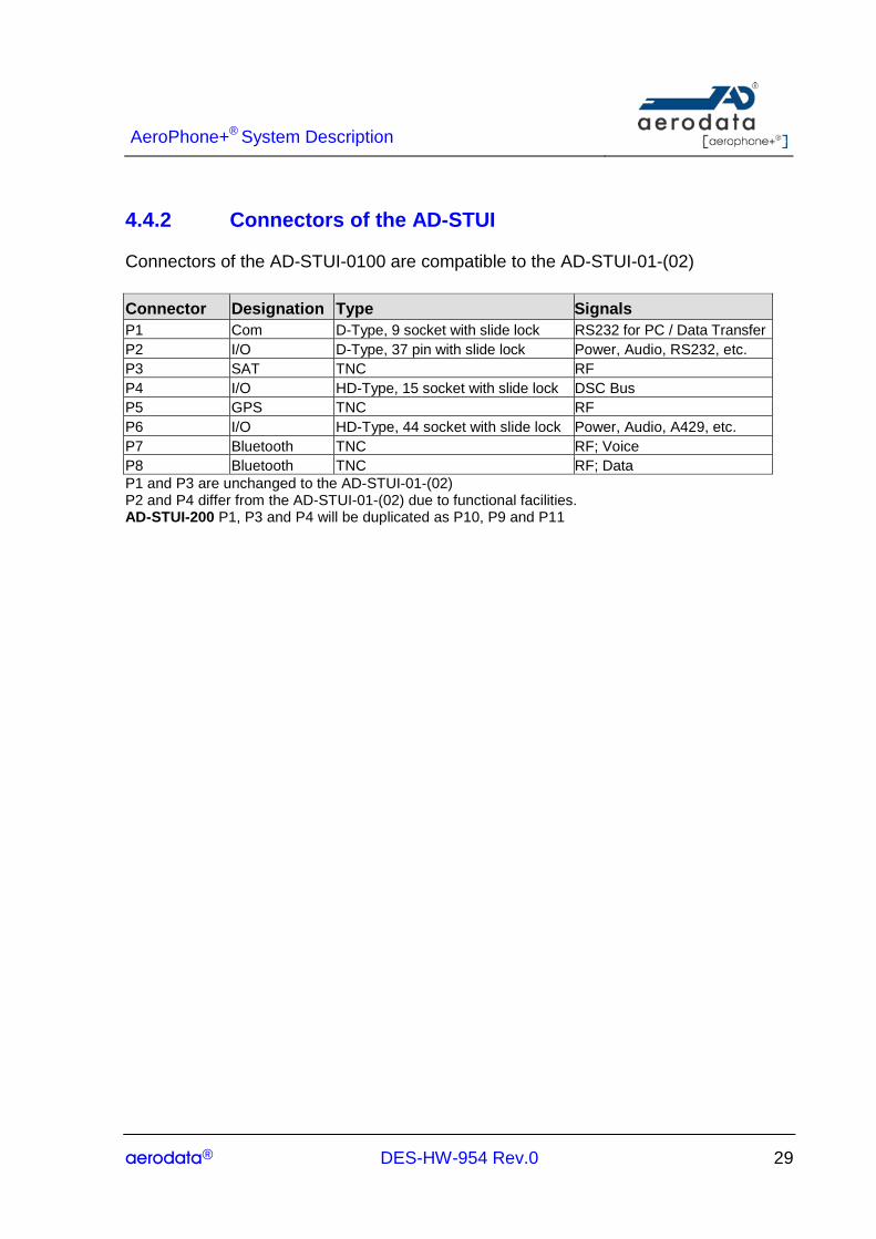
4.4.2 Connectors of the AD-STUI
Connectors of the AD-STUI-0100 are compatible to the AD-STUI-01-(02) Connector Designation Type Signals P1 Com D-Type, 9 socket with slide lock RS232 for PC / Data Transfer P2 I/O D-Type, 37 pin with slide lock Power, Audio, RS232, etc. P3 SAT TNC RF P4 I/O HD-Type, 15 socket with slide lock DSC Bus P5 GPS TNC RF P6 I/O HD-Type, 44 socket with slide lock Power, Audio, A429, etc. P7 Bluetooth TNC RF; Voice P8 Bluetooth TNC RF; Data P1 and P3 are unchanged to the AD-STUI-01-(02) P2 and P4 differ from the AD-STUI-01-(02) due to functional facilities. AD-STUI-200 P1, P3 and P4 will be duplicated as P10, P9 and P11
AeroPhone+® System Description
aerodata® DES-HW-954 Rev.0 30
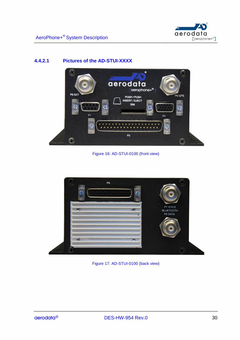
4.4.2.1 Pictures of the AD-STUI-XXXX
Figure 16: AD-STUI-0100 (front view)
Figure 17: AD-STUI-0100 (back view)
AeroPhone+® System Description
aerodata® DES-HW-954 Rev.0 31
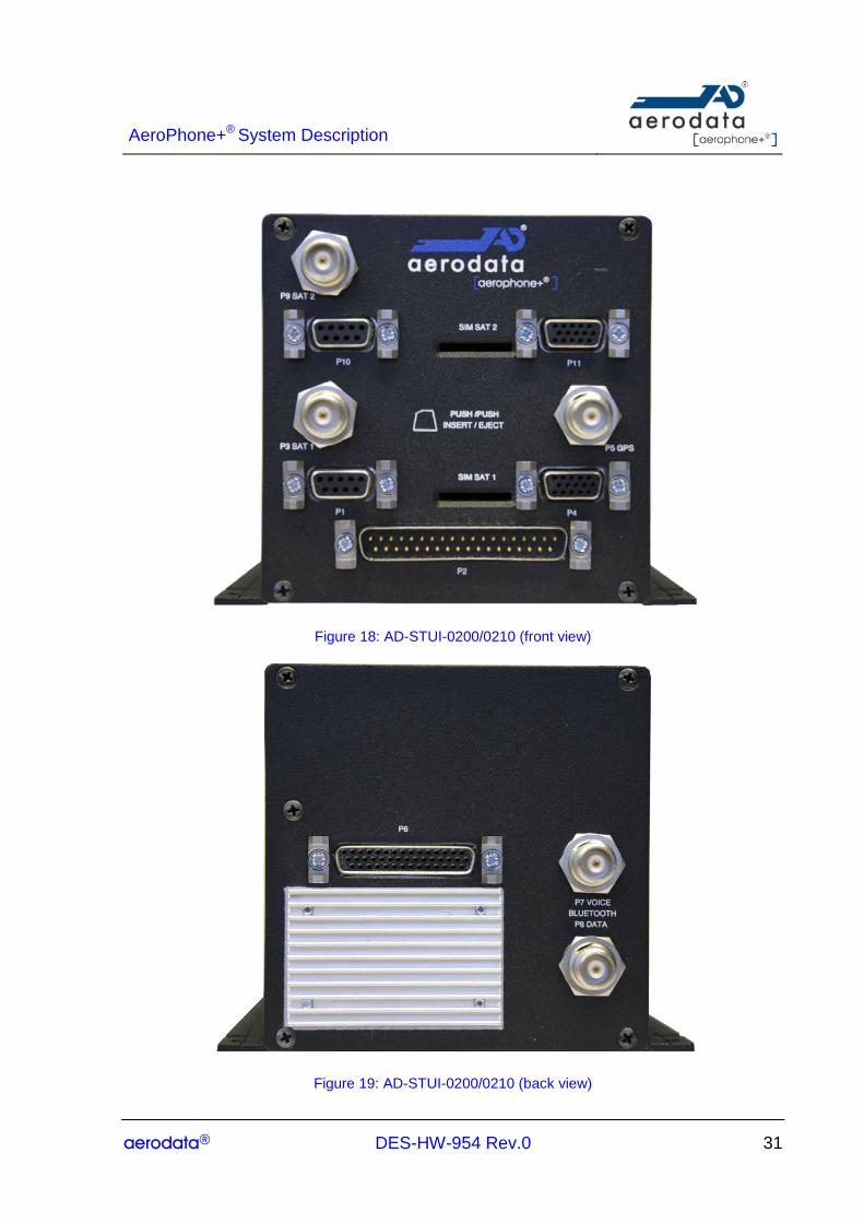
Figure 18: AD-STUI-0200/0210 (front view)
Figure 19: AD-STUI-0200/0210 (back view)
AeroPhone+® System Description
aerodata® DES-HW-954 Rev.0 32
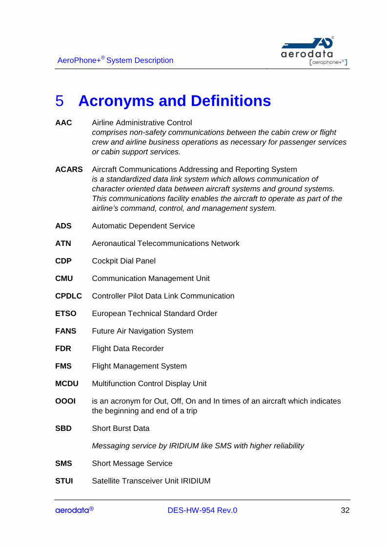
5 Acronyms and Definitions AAC Airline Administrative Control
comprises non-safety communications between the cabin crew or flight crew and airline business operations as necessary for passenger services or cabin support services.
ACARS Aircraft Communications Addressing and Reporting System is a standardized data link system which allows communication of character oriented data between aircraft systems and ground systems. This communications facility enables the aircraft to operate as part of the airline’s command, control, and management system.
ADS Automatic Dependent Service
ATN Aeronautical Telecommunications Network
CDP Cockpit Dial Panel
CMU Communication Management Unit
CPDLC Controller Pilot Data Link Communication
ETSO European Technical Standard Order
FANS Future Air Navigation System
FDR Flight Data Recorder
FMS Flight Management System
MCDU Multifunction Control Display Unit
OOOI is an acronym for Out, Off, On and In times of an aircraft which indicates the beginning and end of a trip
SBD Short Burst Data
Messaging service by IRIDIUM like SMS with higher reliability
SMS Short Message Service
STUI Satellite Transceiver Unit IRIDIUM
AeroPhone+® System Description
aerodata® DES-HW-954 Rev.0 33
UMTS Universal Mobile Telecommunications System
VDL VHF Data Link
WLAN Wireless Local Area Network