aerodynamics at the particle level - penn...
TRANSCRIPT

Aerodynamics at theParticle Level
v.10
Charles A. CrummerUniversity of California, Santa Cruz (ret.)
January 28, 2013
1
arX
iv:n
lin/0
5070
32v1
0 [
nlin
.CD
] 2
3 Se
p 20
12

Contents
1 Preface 1
2 Introduction 2
3 Total force on the surface of the airfoil 4
3.1 Physical parameters affecting the pressure on the airfoil . . . . . 5
4 Mechanics of fluid interaction 6
4.1 Fluid flow over a flat surface . . . . . . . . . . . . . . . . . . . . . 7
4.2 Fluid flow over a curved surface . . . . . . . . . . . . . . . . . . . 8
4.3 Buoyant lift . . . . . . . . . . . . . . . . . . . . . . . . . . . . . . 12
4.4 Vortex fluid motion . . . . . . . . . . . . . . . . . . . . . . . . . . 13
4.5 Finite wings and wingtip vortices . . . . . . . . . . . . . . . . . . 14
4.6 Leading Edge Extensions . . . . . . . . . . . . . . . . . . . . . . 15
4.7 Birds in flight . . . . . . . . . . . . . . . . . . . . . . . . . . . . . 16
5 Bernoulli flow and Coanda flow 16
5.1 Bernoulli’s equation . . . . . . . . . . . . . . . . . . . . . . . . . 16
5.2 Bernoulli at the particle level . . . . . . . . . . . . . . . . . . . . 19
5.2.1 Venturi’s tube . . . . . . . . . . . . . . . . . . . . . . . . 20
5.2.2 The two-fluid atomizer . . . . . . . . . . . . . . . . . . . . 22
5.2.3 Conventional atomizer . . . . . . . . . . . . . . . . . . . . 24
5.2.4 Flit gun . . . . . . . . . . . . . . . . . . . . . . . . . . . . 25
5.2.5 Flow into an expansion chamber . . . . . . . . . . . . . . 26
5.3 The Joule-Thomson effect . . . . . . . . . . . . . . . . . . . . . . 27
2

6 The Coanda effect 29
6.1 Organ pipe beard . . . . . . . . . . . . . . . . . . . . . . . . . . . 29
6.2 The Bunsen burner . . . . . . . . . . . . . . . . . . . . . . . . . . 31
6.3 The Coanda propelling device . . . . . . . . . . . . . . . . . . . . 31
7 Calculation of lift 32
7.1 Using Newton’s Third Law: Effects on the air caused by thepresence of the airfoil . . . . . . . . . . . . . . . . . . . . . . . . . 34
7.2 Using Newton’s Second Law: Effects on the airfoil caused directlyby air pressure . . . . . . . . . . . . . . . . . . . . . . . . . . . . 38
8 Stalling wing 41
9 Rocket engine diffuser 41
9.1 The diffuser . . . . . . . . . . . . . . . . . . . . . . . . . . . . . . 42
10 The high-bypass turbofan jet engine 43
11 The vortex refrigerator 45
12 The Dyson Air MultiplierTM
fan 46
13 Spinning objects in the flow: the Magnus effect 47
14 Gurney and Fowler flaps 48
15 Slots and slats 49
16 Summary 50
17 Conclusion 50
A On the consideration of fluids at the particle level 52
3
B Henri Coanda’s Propelling Device 63
4

List of Figures
1 Velocity profile in the boundary layer for laminar flow . . . . . . 3
2 Interaction between fluid particles and a real surface . . . . . . . 7
3 Fluid flow over curved and flat surfaces . . . . . . . . . . . . . . 9
4 Behavior of particle flow over a curved surface . . . . . . . . . . . 10
5 Flows over a Wing . . . . . . . . . . . . . . . . . . . . . . . . . . 12
6 The vortex process . . . . . . . . . . . . . . . . . . . . . . . . . . 14
7 Downwash and wingtip vortices . . . . . . . . . . . . . . . . . . . 15
8 Pitot tube . . . . . . . . . . . . . . . . . . . . . . . . . . . . . . . 18
9 Venturi tube . . . . . . . . . . . . . . . . . . . . . . . . . . . . . 20
10 Theoretical atomizer . . . . . . . . . . . . . . . . . . . . . . . . . 22
11 Air velocity in the tube . . . . . . . . . . . . . . . . . . . . . . . 23
12 dV/dt to achieve the correct velocity . . . . . . . . . . . . . . . . 24
13 Real atomizer . . . . . . . . . . . . . . . . . . . . . . . . . . . . . 25
14 Nozzle Detail . . . . . . . . . . . . . . . . . . . . . . . . . . . . . 25
15 Flit Gun . . . . . . . . . . . . . . . . . . . . . . . . . . . . . . . . 26
16 Restricted exit orifice . . . . . . . . . . . . . . . . . . . . . . . . . 27
17 Joule-Thomson apparatus . . . . . . . . . . . . . . . . . . . . . . 28
18 Beard on an organ flue pipe . . . . . . . . . . . . . . . . . . . . . 30
19 Bunsen Burner . . . . . . . . . . . . . . . . . . . . . . . . . . . . 31
20 Typical force configuration on an airfoil in an air flow . . . . . . 33
21 Geometry outside the airfoil . . . . . . . . . . . . . . . . . . . . . 35
22 Illustration of the covariant derivative. . . . . . . . . . . . . . . . 36
23 Bending of the airflow by an airfoil. . . . . . . . . . . . . . . . . . 38
24 Coanda effect geometry. . . . . . . . . . . . . . . . . . . . . . . . 40
5
25 Detail at the Diffuser Wall . . . . . . . . . . . . . . . . . . . . . . 43
26 Early turbojet . . . . . . . . . . . . . . . . . . . . . . . . . . . . 44
27 The entrance cowl for an Airbus A380 turbofan engine . . . . . . 44
28 Ducted fan tailrotor . . . . . . . . . . . . . . . . . . . . . . . . . 45
29 Vortex tube schematic . . . . . . . . . . . . . . . . . . . . . . . . 45
30 Vortex tube flow . . . . . . . . . . . . . . . . . . . . . . . . . . . 45
31 The Dyson Air MultiplierTM
fan . . . . . . . . . . . . . . . . . . 47
32 Operation of the Dyson Air MultiplierTM
fan . . . . . . . . . . . 47
33 Cross section of the Dyson Air MultiplierTM
fan . . . . . . . . . . 47
34 The Magnus effect . . . . . . . . . . . . . . . . . . . . . . . . . . 48
35 Gurney flap . . . . . . . . . . . . . . . . . . . . . . . . . . . . . . 49
36 High-lift wing devices . . . . . . . . . . . . . . . . . . . . . . . . 50
6
Abstract
All aerodynamic forces on a surface are caused by collisions of fluidparticles with the surface. Upwash, downwash, lift, drag, the startingvortex, the bow wave, and any other phenomena that would not occurwithout the surface are caused by its presence as it interacts with the airflow. While the standard approach to fluid dynamics, which is founded onthe “fluid approximation,” is effective in providing a means of calculatinga wide range of fluid behavior, it falters in its ability to account for theeffects of complex interactions of the fluid either with itself, other fluids,or with solid bodies. One of the conditions required to justify the fluidapproximation is that the flow be steady[21], i.e. that the particles of thefluid not be interacting with each other or with any surface. It is thesevery interactions, however, that are the causes of aerodynamic effects onsolid bodies in the flow. This is not to say, of course, that the fluidapproximation is never useful, but that some well-known and importanteffects such as the Coanda effect are not explained by that model.
i

1 Preface
The purpose of this paper is to set the stage for a close examination of fluid phe-nomena, an examination at the particle level. Most fluid phenomena of interestare the result of its behavior in interaction with surfaces, other fluids or, indeed,with itself. The eddies and turbulence attendant fluid shear are extremely com-plex. As one fluid is injected into another, the shear effects depend further onthe different attributes of the fluids. If a fluid is flowing, it is doing so withrespect to something, a surface for instance.
A dimensionless quantity used to characterize the nature of fluid flow is Reynolds’number:
R =ρvL
η
where
ρ is the density of the fluid,
v is its velocity,
η is the fluid’s viscosity and
L is called “a characteristic length.”
What does “characteristic length” mean? L is a length that is defined only interms of the boundaries of the flow such as the diameter of a tube or the chordlength of an airfoil. What length is it and why? In fact, Reynolds’ number isonly well-defined in discussions of model scaling of fluid flows in interaction withsolid surfaces. For example the characteristics of a flow around a boat with abeam of 4 meters in an ocean current of 10 knots will be the same for a scalemodel of the boat in the same ocean water whose beam is 0.4 meters and wherethe current is 100 knots.
What meaning can references to Reynolds’ number have?
Bernoulli’s relation involves the fluid velocity. In a Venturi tube, it is the velocitywith respect to the wall of the tube. If a high fluid velocity implies a low pressure,how can the pressure readings in different parts of the tube be different sincethe sensors are in the boundary layer of the fluid at the surface of the wall ofthe tube? The boundary layer is stationary.
It is these and other baffling questions that has launched the author into theseinvestigations.
Even though aerodynamics engineers are masters at designing airframes, theyare refining known technology. Without understanding from first principles,
1

lighting engineers would just be refining incandescent lamps and we would nothave fluorescent lights or LEDs.
2 Introduction
The behavior of real fluids, i.e., compressible and viscous, is to this day bafflingin many ways. Part of the reason is that explanations of fluid behavior arehold-overs from the pre-twentieth century belief that a fluid is a fundamentalentity, not composed of anything else.[2] The trouble with this approach is thatit provides only viscosity and pressure as ways of understanding how the fluidinteracts with itself or with solid bodies. Both are intensive variables but whatdo they mean for volumes so small that the fluid approximation is not valid?
Pressure, p, (stress normal to a surface) can be understood as that fluid propertywhich causes a normal force on a surface in the flow,
dFn = p(s) dA.
The shear force provides part of the drag on a surface. It is derived from theshear stress, τ , tangential to the surface.
dFs = τ ⊗ dA,
where
τ ≡ µS(r, s)r=R(s). (1)
Here,
s is the location on the surface of the airfoil,
r is a length in the direction normal to the surface,
R(s) is the radius of curvature at s,
v(s, r) is the velocity of the flow relative to the surface,
µ is the dynamic viscosity of the fluid,
S(r, s) = ∂v(r, s)/∂r is the shear and
τ is the resulting shear stress on the surface.
2

Figure 1 shows qualitatively the velocity profile in the boundary layer duringlaminar flow. The curve is differentiable and indicates that there is slip thesurface. Admitting the possibility of slip at the airfoil surface is contrary tothe no-slip assumption of Ludwig Prandtl[8] but in view of the development inSection 4 below and the work of Johan Hoffman and Claes Johnson,[17] there isreason to suspect the reality of the no-slip assumption. At the surface, becauseof the interaction of the particles in the flow with each other and with the(possibly submicroscopic) features of the surface, the behavior is very complexbut for laminar flow this structure is smoothed out as the disturbance recedesinto the flow.
A common example of this is the bow-wave of a slowly moving boat. Closeinspection of the behavior of the water at the bow reveals great complexity butfar from the boat the wave is very regular and smooth.
Figure 1: Velocity profile in the boundary layer for laminar flow
In order that the viscosity, τ, as defined in Equation (1) have meaning, thefunction v(s, r) must be smooth and differentiable. However, as the flow velocityincreases, there is an onset of turbulence. The boundary layer develops eddiesnear the surface [8] and v(s, r) becomes non-differentiable and so the partialderivative in Equation (1) ceases to exist. The behavior of the fluid becomesvery complex and the flow becomes unsteady; the fluid assumption becomesinvalid.
Since the work of Boltzmann [3] and Einstein [7], i.e., theory based on the postu-late, and supporting evidence that fluids are composed of tiny particles, deeperinsight is possible by considering in detail the interactions of these particles witheach other, those of other fluids, and those of solid bodies in the flow. In factit may be helpful to remember that the only interactions a fluid can have, ac-cording to this model, are through momentum transfer or Van der Waals forcesbetween its particles and between the particles and the surface.1 The moleculesof a gas at standard pressure are only within van der Waals distance 1/100th
1We do not consider plasmas, which are affected by long-range electromagnetic forces.
3

of the time they are apart so these forces only play a part in particle-particlescattering.
The notion, therefore, that a streamline in a gas flow is “attracted” by a surfaceis not correct. If a stream of gas, as in Coanda flow,[9] seems attracted to asolid object it is due to its self-interaction, interaction with gas outside the flow,and the forces its particles exert on the surface as they strike it, not due to anattractive force between the particles and the surface. In contrast to the workof Bernoulli, there is no “Coanda equation” because, other than Newton’s laws,we have no physical model for the behavior of the particles in the boundarylayer. Henri Marie Coanda was an engineer and observed effects that are widelyincorporated into modern aerodynamic design but physicists have not developeda tractable mathematics to describe the behavior of such a large number, ∼ 1023,of simple interactions without the fluid assumption. In any case, to explorea mathematical model is not the same as to explore the physical world (SeeAppendix A). One goal of theoretical physics is the calculation of the resultsof experiments, another is to understand why the world works as it does. Themiracle is that mathematics is as useful as it is in describing and predictingphysical effects.
The statements made below about fluid flow are conclusions and hypothesescoming from a consideration of particles obeying Newton’s laws. The author’sintention is to stimulate the reader’s thoughts about the behavior of fluids inregimes where the flow is not steady, and hence the fluid assumption is invalid.Another aim of this paper is to discern causes of phenomena. A mathematicalequation does not contain causal information. For example, the thrust of arocket is not caused by the velocity of the exiting gases but by the pressuredifference between the throat and the projection along the axis of the motor ofthe throat area onto the back wall of the motor. Bernoulli’s equation relatesthe the exit velocity and the pressure difference but conveys no information asto which is the cause and which is the effect. It is only from experience withthe physical world and abstractions of that experience that one knows that inNewton’s second law it is force that causes acceleration, not the reverse.
It is hoped that an understanding of the true causes of aerodynamic effects willlead to new aerodynamic designs and the rethinking of designs already created.Imagine, for a moment, that in the absence of a tractable mathematical model,non-mathematical understanding is possible.
3 Total force on the surface of the airfoil
For perfectly elastic collisions the effect on a surface over an area ∆A results ina force, ∆F with components normal and transverse to the area.
∆F = m∑
∆A
ai
4
where m is the mass of one particle and the ai are the accelerations of theparticles hitting the surface area ∆A and the summation is over the area. Thenormal components of the ai’s are due to pressure and the transverse compo-nents are due to the viscous interaction of the fluid with the surface and withitself.
As the particles move over the surface, they are affected by the molecular pro-tuberances on the surface and by Van der Waals forces between the particlesand the surface. This friction, i.e., viscosity, force is proportional to the area∆A as well.
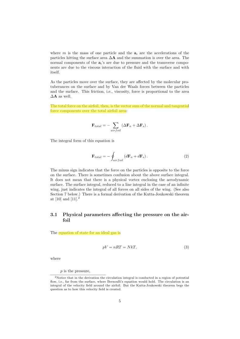
The total force on the airfoil, then, is the vector sum of the normal and tangentialforce components over the total airfoil area:
Ftotal = −∑
airfoil
(∆Fn + ∆Fs) .
The integral form of this equation is
Ftotal = −∮
airfoil
(dFn + dFs) . (2)
The minus sign indicates that the force on the particles is opposite to the forceon the surface. There is sometimes confusion about the above surface integral.It does not mean that there is a physical vortex enclosing the aerodynamicsurface. The surface integral, reduced to a line integral in the case of an infinitewing, just indicates the integral of all forces on all sides of the wing. (See alsoSection 7 below.) There is a formal derivation of the Kutta-Joukowski theoremat [10] and [11].2
3.1 Physical parameters affecting the pressure on the air-foil
The equation of state for an ideal gas is
pV = nRT = NkT, (3)
where
p is the pressure,
2Notice that in the derivation the circulation integral is conducted in a region of potentialflow, i.e., far from the surface, where Bernoulli’s equation would hold. The circulation is anintegral of the velocity field around the airfoil. But the Kutta-Joukowski theorem begs thequestion as to how this velocity field is created.
5

V is volume,
n is the number of moles of gas in V ,
R is the gas constant and
T is the Kelvin temperature.
N is the number of particles in V and
k is Boltzmann’s constant, ∼ 1.38× 10⁻²³ (m2kg)(sec2 ◦K)
Also, the density, ρ is
ρ =nm
V×N, (4)
where N = 6.02 × 10²³ is Avogadro’s constant, the number of particles in onemole.
Making the ideal gas assumption then,
p =ρ
NmRT. (5)
Far away from the airfoil, the pressure, p, is approximately constant and uni-form except for the effect of gravity and the presence of the airfoil[11]. Thecompressibility of air can be ignored. But on the surface of the airfoil, it is pre-cisely pressure differential that causes lift. Equation (5) reveals that ρ,m and T ,subject to the laws of thermodynamics, are at the disposal of the aeronauticalengineer for creating a favorable pressure field on the airfoil’s surface.
4 Mechanics of fluid interaction
Aerodynamic forces affecting a rigid surface are always net forces producedby differences in pressure between different parts of the surface. The absolutepressure on a surface area element is the density of the normal components ofthe forces acting on the surface there.
Aerodynamic forces on a body are caused only by collisions of fluid particleswith the body’s surface.3 At the molecular level, the flow particles encounterany surface as a molecular structure which is rough, with protuberances whosesize is of the order of magnitude of the flow particles themselves (see Figure 2.).As particles collide with the surface, their momentum components normal to
3The Coanda effect in liquid-surface flow, however, may be caused in large part by van derWaals forces, which are attractive.
6

Figure 2: Interaction between fluid particles and a real surface
the surface there cause lift, positive or negative, and stagnation pressure andthe parallel components cause viscous drag and give rise to a boundary layerwhich is carried along by the surface (see Ref. [8]). It is clear, then, that themicroscopic structure of the surface and the properties of the fluid will affectdrag and lift, even for Φ = 0. A perfectly smooth surface would have no viscousdrag, there would be no shear in the fluid near the surface and, it would appear,a wing made of this material would have lift only if the air flow momentumdensity had components normal to the bottom surface of the wing, i.e. due tothe angle of attack, Φ.
Even though these momentum transfers occur only in the boundary layer thatappears to be “dragged along” by the surface, they are responsible for the wholeof lift and drag. Actually, fluid particles can leave and enter the boundary layerby moving normal to the surface. Dust on a surface in a flow is not disturbedlaterally because the boundary layer is motionless, or nearly so, at the surface.The boundary layer is created by the interaction of the main flow particleswith particles bouncing off the surface. For the time being, we assume that allcollisions, particle-particle and particle-surface, are perfectly elastic and thatthe particles are spheres.
4.1 Fluid flow over a flat surface
Let us consider the flat surface in panel a) of Figure 3. The pressure on thesurface is due only to the normal components of the momenta of the impactingparticles. Flow along such a surface will not affect surface pressure. As particlesare blown away from the surface, other particles are drawn in from outside toreplace them.4 Pressure on the surface is due to collisions of particles with thesurface. Where the flow has no normal component, the pressure is due only tothe thermal motion and density of the particles in the boundary layer, i.e. thestatic atmospheric pressure. Hence this pressure will be a function only of themass of a particle, the particle density, and Kelvin temperature of the air at thesurface.
4Place a sheet of paper flat on your hands. Blow over the top surface of the paper. Thisexperiment refutes the notion that the pressure in a free flow is less than the ambient staticpressure. Bernoulli flow, on the other hand, is (or could be) confined to a tube and is not free.
7

In reality, the fluid particles in a layer around a surface boundary seem tobe carried along with the surface, i.e. the distribution of the components oftheir velocities parallel to the surface is nearly[17] circularly symmetric abouta mean which is the velocity of the surface relative to the free-stream velocity.5
Particles, as large as dust particles or as small as the molecules making up theflow, experience Van der Waals forces attracting them to the surface. Whetheror not the particles are fixed on the surface by these forces depends on thestructure of the molecules making up the flow and those making up the surface.These Van der Waals forces are responsible for the “wetting” of the surface. Insome cases, e.g. Teflon and water, the fluid drains off the surface quite readilyjust under the force of gravity. In other cases, e.g. modern motor oil on abearing surface, the fluid may adhere for months or even years.
In any case, however, particles continually leave the boundary layer and enterit transversely from the flow due to heat energy or, at an angle of attack, be-cause they have velocity components normal to the surface.6 Beyond a meanfree path7 or so but still in the boundary layer, the distribution of the normalcomponents of particles’ velocities moving toward or away from the surface willdepend on the temperature and density of the particles. Even though it is regu-larly driven at high speed, a car will accumulate dust on its body. An air streamdirected toward the surface, however, will blow off some of that dust. As we willsee, it is the mutual interaction of flow particles and these “stagnant” boundarylayer particles that is responsible for a part of the lift on an airfoil at subsonicspeeds.
An increase in the free-stream velocity means that the components of the veloc-ities of the flow particles increase in the direction of the free-stream velocity andparallel to the surface. The reason that the boundary layer remains quiescent,or nearly so, is that the components of the colliding particles’ velocities parallelto the surface reverse as they collide with microscopic irregularities. This is oneof the causes of aerodynamic drag and accounts for the fluid’s viscosity.8 If thecollisions are not perfectly elastic, the rebound speed is less than the incidentspeed and the surface absorbs some of the particle’s energy, i.e. it heats up.
4.2 Fluid flow over a curved surface
In a steady flow over a surface, stream particles have only thermal velocitycomponents normal to the surface. If the surface is flat, the particles that collidewith boundary layer particles are as likely to knock them out of the boundary
5This property of fluid flow was utilized by Nicola Tesla [1] in his unique design of a rotarypump.
6It can be seen, then, that dust particles on a surface in an air flow are not disturbed notbecause the fluid particles are necessarily entrained but that they come and go normal to thesurface. Hence they do not impart lateral forces to the dust particles.
7∼ 9 × 10⁻⁸ meters for N2 at standard pressure and temperature.8Though viscosity is supposed to be a property of the fluid, it is measured by the terminal
velocity of a ball in the fluid or the force it takes to slide two plates with the fluid betweenthem. Viscosity, then, has to do with the interaction of the fluid with itself as well as withsolid bodies.
8

Figure 3: Fluid flow over curved and flat surfaces
layer as to knock others in, i.e. the boundary layer population is not changedand the pressure on the surface is the same as if there were no flow. If, however,the surface curves away from the flow direction, the particles in the flow will tendto take directions tangent to the surface, i.e. away from the surface, obeyingNewton’s first law. As these particles flow away from the surface, their collisionswith the boundary layer thermal particles tend to knock those particles awayfrom the surface. What this means is that if all impact parameters are equallylikely, there are more ways a collision can result in a depletion of the boundarylayer than an increase in the boundary layer population. The boundary layerwill tend to increase in thickness and to depopulate and, according to Equations(4) and (5), the pressure will reduce there. This is why the flow is forced towardthe surface, the Coanda effect with the attendant suction that draws in fluid farfrom the surface.9 Those particles in the flow that do interact with the stagnantboundary layer will give some of their energy to particles there. As they aredeflected back into the flow by collisions with boundary layer particles, theyare, in turn, struck by faster particles in the flow and struck at positive impactparameters.
The following, Figure 4, consists of 4 frames taken from an animation[26] illus-trating the behavior of flow particles as they interact with stagnant particlesin the boundary layer. The first panel shows the incoming particles in red ap-proaching from the right. In the second panel the incoming particles begin tointeract with the stagnant particles meant to approximate a boundary layer.The third panel shows the boundary particles being blown away by the incom-ing set, thus reducing the pressure at the surface. As panel four shows, it isprimarily the boundary layer particles that make up the flow that clings to thecurved surface.
These frames show, at least qualitatively, the Coanda effect. The figures areframes taken from an animation made with Working ModelTM[25] software. Inthe video, approximately 600 small circles are launched toward a fixed circle withstagnant circles positioned around it, meant to simulate a boundary layer. Allcollisions are perfectly elastic and the large circle has infinite mass. Of course,
9This explanation suggests experiments exploring the structure at the edge of the mainflow that is away from the wall. The explanation of the mechanism by which the flow is“attracted” to the wall implies how the flow should behave at its other edge too.
9

Figure 4: Behavior of particle flow over a curved surface
this model is highly unrealistic because of the very small number of particles,their simple circular structure, the smoothness of the surface and the absenceof thermal motion. It does, however, show boundary layer depletion and the“wrapping” of the flow around the surface. A more accurate simulation wouldhave a continuous flow impinging on a rough surface surrounded by particles.All the particles should be interacting thermally with each other and with thesurface. Notice also that the wrapped flow contains almost none of the redincoming particles.
In reality, the flow shears past the surface (where the molecular motion is com-plex and chaotic) and the fluid velocity as a function of the distance normalto the surface is a smooth function of this distance. The velocity profile curveparameters are constants depending on the fluid velocity, the physical charac-teristics of the surface and the particles making up the fluid (See Figure 1). Inany case, as the flow velocity increases, separation points will begin to appear[8].These are the points on the surface where the directional derivative of the fluidvelocity normal to the surface vanishes as does the shear (Equation (1)). Asthe fluid velocity increases even further, the derivatives at the separation points
10

actually reverse sign, there is backward flow on the surface.[8] Vortices haveformed downstream from these stagnation points. All this is in the language offluids. What is going on at the particle level though?
The curved part of the surface acts as the obstruction mentioned in the ex-planation of the vortex process (See Section 4.4.) because it presents stagnantparticles to the flow. The flowing particles as they approach the surface interactwith these particles and with the surface itself. Some populate the boundarylayer and then interact as stagnant particles with other particles in the flow.There is a constant interchange of particles between the boundary layer andthe flow. As these interactions take place the process described above activatesthe boundary layer particles like falling dominoes, causing the enveloping flow.When the surface curves away from the flow, the flow particles, obeying New-ton’s first law, tend to travel on trajectories tangent to the surface and thusleave its vicinity, taking some boundary layer particles with them. This reducedpressure in the boundary layer has two effects. First, it causes the higher pres-sure in the main flow to force itself, and smoke streamers, toward the surface,and second, it results in lift as the higher pressure on the bottom of the winghas increased effect.
The Coanda effect is investigated in some detail in articles in Deutsche Luft-und Raumfahrt[23]. H. Riedel’s paper has numerous diagrams of flow patternsand distributions of pressure differentials on a wing surface in various positionswith respect to an air jet. Figure 5 is from this paper.
The first panel in Figure 5 shows the flow of and around a free stream in anatmosphere. Note the entrainment of air from outside the stream. Panels 2and 3 show flow and distributions of pressure differentials on a wing in the flow.Note that in panel 3 there is a sharp spike in downward pressure where theflow actually impinges vertically on the surface. This downward pressure is thecause of wing stall. Flow along a positively curved surface causes a lowering ofthe pressure on the wing but for flow rates above a certain velocity a vortex willbe created which can cause an increase of pressure there.
The Coanda effect gives a hint at at what turns out to be the most importantcause of lift at zero or small angle of attack and subsonic conditions. Whileit may be intuitive that to increase lift the pressure under the wing, and thusthe angle of attack, should be increased, in fact for a fixed wing it is moreimportant to decrease the pressure on the top of the wing. (See Reference [15],page 181.) Professor Marco Colombini at the University of Genoa, Italy[18]has produced some interesting animations illustrating the pressure distributionaround a standard airfoil at varying angles of attack.10 It is interesting to thinkof airfoil design as an exercise in managing buoyancy.
10These pressure distributions, however, do not show the bow wave the same as it is seenin Figure 20.
11
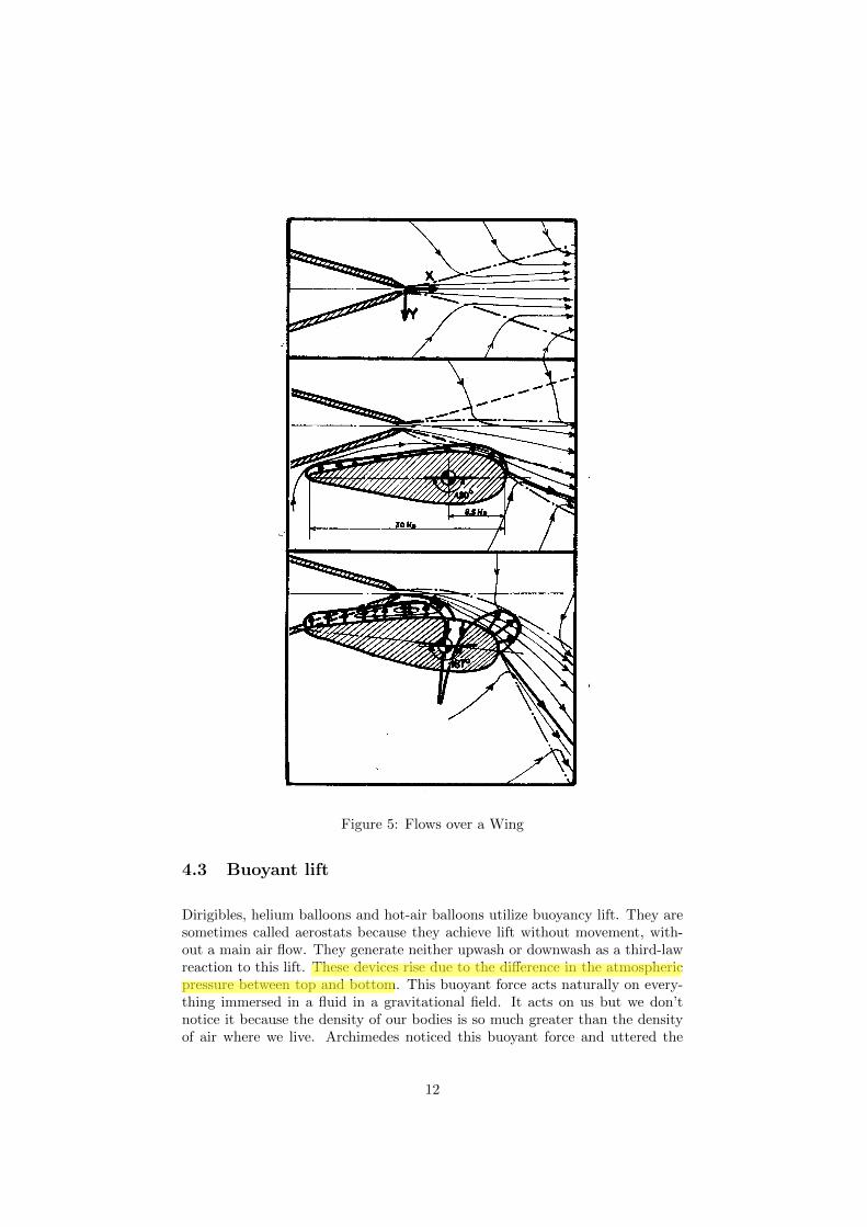
Figure 5: Flows over a Wing
4.3 Buoyant lift
Dirigibles, helium balloons and hot-air balloons utilize buoyancy lift. They aresometimes called aerostats because they achieve lift without movement, with-out a main air flow. They generate neither upwash or downwash as a third-lawreaction to this lift. These devices rise due to the difference in the atmosphericpressure between top and bottom. This buoyant force acts naturally on every-thing immersed in a fluid in a gravitational field. It acts on us but we don’tnotice it because the density of our bodies is so much greater than the densityof air where we live. Archimedes noticed this buoyant force and uttered the
12

famous “Eυρηκα !” He knew how to measure the density of the king’s crownand to test if it was pure gold.
One might think that the buoyant force, which is due to the gravitational field,would be negligible for an airplane because the airplane’s overall density is muchgreater than air at standard conditions. However, see Section 6 below. Sincethe buoyant force is due to the pressure differential between the top of a bodyand the bottom, the buoyancy can be managed by controlling these pressures.
4.4 Vortex fluid motion
As a fluid stream passes through an opening in a barrier into stagnant fluid,eddies appear. Consider the state of the fluid as the flow begins. Behind thebarrier the distribution of velocities of the particles of the fluid in a small volumeis spherically symmetric (except for the effect of gravity) and the mean of thedistribution is a function of the Kelvin temperature.
Upstream, the pressure behind the barrier is higher than the pressure behindthe exit. A particle on a streamline just grazing the barrier encounters particlesbehind that barrier whose mean velocities are zero. Downstream of the barrier,the result of collisions with these stagnant particles is the slowing of a flowparticle as well as its deflection back into the flow. (See Figure 6.)
The greater the difference between the flow velocity and the thermal velocitiesof the stagnant particles, the closer to 90◦ from the flow direction will be thedirections of the stagnant particles after the collisions. Thus the interaction be-tween the stream and the stagnant region serves to sort out the colder stagnantparticles and force them away from the flow. The vortex heat pump describedlater in Section 11, Figures 29 and 30 uses this principle.
As the stream particles that have suffered collisions with stagnant particles arehit by faster ones in the stream, they too are deflected with a velocity componentnormal to the stream velocity. As they continue after being deflected away fromthe stream, they hit other stagnant particles (Figure 6), forcing them towardthe same center. The result is that part of the flow is changed into a vortex. Ifthe obstruction is a hole in a plate, some of the energy of the flow is trapped inthe form of a vortex ring. If the flow is a pulse, this ring follows in its wake.
Let the lower half of the y-z plane be a barrier in the fluid. (See Figure 6.) Thevelocity of the flow will be superimposed on the random motion of the molecules,i.e. heat. As the flow begins, say from minus to plus in the x-direction, themean of the distribution of the velocities of those particles in the flow will beshifted toward positive vx . As these particles pass the barrier, they collide withfluid particles that have a velocity distribution with zero mean, i.e. the stagnantparticles.
Call an impact parameter positive if the location of the impact point with aparticle in the flow is a positive distance in y from the center of one of these
13
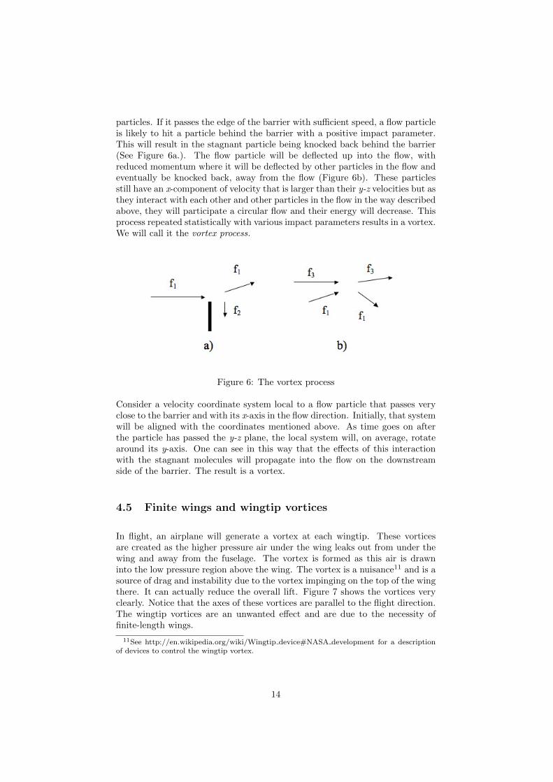
particles. If it passes the edge of the barrier with sufficient speed, a flow particleis likely to hit a particle behind the barrier with a positive impact parameter.This will result in the stagnant particle being knocked back behind the barrier(See Figure 6a.). The flow particle will be deflected up into the flow, withreduced momentum where it will be deflected by other particles in the flow andeventually be knocked back, away from the flow (Figure 6b). These particlesstill have an x-component of velocity that is larger than their y-z velocities but asthey interact with each other and other particles in the flow in the way describedabove, they will participate a circular flow and their energy will decrease. Thisprocess repeated statistically with various impact parameters results in a vortex.We will call it the vortex process.
Figure 6: The vortex process
Consider a velocity coordinate system local to a flow particle that passes veryclose to the barrier and with its x-axis in the flow direction. Initially, that systemwill be aligned with the coordinates mentioned above. As time goes on afterthe particle has passed the y-z plane, the local system will, on average, rotatearound its y-axis. One can see in this way that the effects of this interactionwith the stagnant molecules will propagate into the flow on the downstreamside of the barrier. The result is a vortex.
4.5 Finite wings and wingtip vortices
In flight, an airplane will generate a vortex at each wingtip. These vorticesare created as the higher pressure air under the wing leaks out from under thewing and away from the fuselage. The vortex is formed as this air is drawninto the low pressure region above the wing. The vortex is a nuisance11 and is asource of drag and instability due to the vortex impinging on the top of the wingthere. It can actually reduce the overall lift. Figure 7 shows the vortices veryclearly. Notice that the axes of these vortices are parallel to the flight direction.The wingtip vortices are an unwanted effect and are due to the necessity offinite-length wings.
11See http://en.wikipedia.org/wiki/Wingtip device#NASA development for a descriptionof devices to control the wingtip vortex.
14

Figure 7: Downwash and wingtip vortices
Though the wingtip vortices are beautiful and spectacular, the concomitant tothe most important factor in producing lift is the huge trench left in the cloudby the downwash off the trailing edges of the wings.
The French jet engine manufacturing company, Price Induction12 sells smallhigh bypass engines for small aircraft. One of their innovations is a turbofanusing composite, non-metallic blades. At speed, the fan blades elongate andactually seal on the special bearing surface of the fan housing. The reason forthis is to eliminate vortices at the vane tips. This reduces power requirements,increases the engine efficiency and increases thrust.
4.6 Leading Edge Extensions
Though wingtip vortices are unwanted, similar vortices are created on purposeby so-called Leading Edge Extension (LEX) surfaces.[22] A LEX is a flat surfaceextending a short distance from the fuselage and from near the cockpit aft tothe leading edge of the wing. At angle of attack vortices are created as thehigh-pressure air flows from below the LEX to the lower pressure above. Thiscauses the vortices, clockwise on the left side and counter-clockwise on the right.These vortices extend back over the wings and interrupt the stalling vortices thatwould otherwise form over the wing. They blow away the particles that wouldcause high pressure on the tops of the wings, especially near the roots. LEXsallow the plane to operate at higher angles of attack than it otherwise could.
12Price Induction, 2, Esplanade de l’Europe 64600 Anglet, FRANCE. www.price-induction.com
15
4.7 Birds in flight
The high-speed camera shows some very interesting aspects of birds takingflight.[6] Perhaps the most interesting is that on take-off, when maximum liftis needed, a bird’s power stroke is down and forward, not backward as it woulddo if it were “swimming” in the air. This motion both pressurizes the air underthe wing and creates upwash13 on the leading edges of its wings. This upwashflows over the leading edge and actually contributes to lowering the pressure onthe top of the wing.
On aircraft, the leading edge slots and slats are designed to control and makeuse of upwash. Trailing edge flaps act like the big feathers on the trailing edgesof a bird’s wings. They help trap the flow and thus increase pressure under thewing and they also extend the wing’s curved surface and hence the region oflow pressure on the top of the wing.
5 Bernoulli flow and Coanda flow
5.1 Bernoulli’s equation
For an incompressible14 fluid in steady[21] flow, a simple expression for theconservation of energy was derived by Daniel Bernoulli in 1737 in his book“Hydrodynamica”. In steady flow, the fluid can be enveloped in an actual orvirtual tube. That means that at any cross-section perpendicular to the tube’swalls, the fluid has a uniform velocity across the tube, i.e. there can be no shearin the fluid. Fluid neither leaves nor enters through the wall of the tube andthe particles do not interact with each other or with the wall of the tube. Andfinally, since the flow must be laminar, the tubes themselves, actual or abstract,are restricted to a smooth, gently varying shape. These assumptions precludeturbulence or eddy formation. If these conditions hold to a good approximation,Bernoulli’s equation holds. If such a tube cannot be drawn, the equation doesnot hold. Bernoulli’s equation allows the calculation of general behavior butbecause of these assumptions the theory is not able to predict other aspects offluid dynamics, such as behavior in the boundary layer of a surface in the flow.
Bernoulli’s equation is:
Energy Density =1
2ρv2 + ρgh+ p. (6)
where
13See Section 1514See, however http://www.efunda.com/formulae/fluids/bernoulli.cfm for a more general
form of the equation which describes the behavior of certain types of compressible fluids.
16
p is the absolute pressure,
ρ is the density of the fluid,
g is the acceleration due to gravity,
h is the height in the gravitational field and
v is the velocity vector for a cell in the flow small enough so that thevelocities of the particles in the cell are approximately equal.
Note that the assumption that the flow consists of these cells amounts to the fluidapproximation. In the particle view the existence of these cells is not assumedand the macroscopic fluid velocity is superimposed on thermal components ofthe particles’ velocities. When the flow is incompressible and steady, the energydensity is conserved in the flow.
Bernoulli’s equation is an expression of the conservation of energy, a checksumthat is very useful in the calculation of the properties of a steady flow. It doesnot speak to the question of cause and effect however. Fluid flow is caused by apressure differential or direct collisions of the fluid particles with surfaces, e.g.a propellor, and is sustained according to Newton’s first law since the particlesare massive. In some circumstances a flow can also give rise to a pressuredifferential, the cause of the Coanda effect. Just because a fluid is flowing doesnot mean that the pressure within the fluid has decreased. Velocity is relative tothe inertial frame where it is measured but pressure is a quantity independentof the inertial frame where it is measured. The pressure in a fluid is measuredas the momentum transfer of the fluid particles striking some transducer thatproduces a pointer reading. The force that moves the pointer is the integralover the (oriented) surface area of the transducer of the rate the fluid particlestransfer momentum to it.
Pointer Reading ∝ Force = m×∑
transducersurface
dv
dt⊗ dA, (7)
where m and v are the particle’s mass and velocity and dA is an area element.We assume that the particle collisions with the surface are perfectly elastic, sothe tensor product, ⊗, gives a result normal to the surface element, dA.
The orientation of the transducer surface in the flow affects the pressure read-ing.15 The tensor product between the area tensor, A and the particle velocityv in Equation (7) is a force which the transducer converts to a pointer reading.A careful examination of a common Pitot tube used to measure the speed ofan airplane (Figure 8) will show that the speed is measured as the difference in
15A Michaelson interferometer with a vacuum chamber in one leg can be used to measureair density from which the pressure can be calculated from thermodynamic principles. It doesnot measure pressure directly however.
17

pressure between pressure sensor areas that are normal to one another in thesame flow. (In the figure, V is the velocity of the aircraft.)
Figure 8: Pitot tube
A Pitot tube is a device to measure air speed, i.e., the velocity of the tube withrespect to the local ambient air. If the tube is correctly mounted on an aircraftflying in air that is not moving with respect to the earth, it measures, afteraltitude correction, the ground speed of the aircraft. It’s design makes use ofBernoulli’s relation. It actually consists of two concentric tubes. The outer tubeis welded to the rim of the inner tube at one end and both tubes are sealed atthe other end except for a manometer or other relative pressure gauge whichis connected between the two tubes. A close examination of one design of aPitot tube will reveal small holes in the side of the exterior tube. These holesare exposed to the air flow. In order for the device to work correctly, it is veryimportant that the surfaces of these holes be parallel to the flow so there is noram pressure or rarefaction of the air there. It is the pressure in the outer tubethat is compared to the ram pressure in the center tube. This pressure remainsat ambient no matter what the air speed, even zero.16 It is the ram pressure inthe inner tube that changes as the airspeed changes.
Although Bernoulli’s equation employs densities as factors in the potential andkinetic energy terms, the equation in this form is only valid when the fluid canbe assumed incompressible and non-viscous because compression heating andviscous interactions create heat energy. To account for this energy, thermo-dynamics would have to enter the equation and a thermodynamic process beidentified. This process could vary in many different ways, depending in de-tail on the specific case. It is for this reason that there is no heating term inBernoulli’s equation. If compression is significant, Bernoulli’s equation in thisform cannot be expected to hold.17
16Ambient pressure is a function of altitude and so a correction must be made to the Pitottube reading.
17See http://www.efunda.com/formulae/fluids/bernoulli.cfm
18

5.2 Bernoulli at the particle level
Strictly speaking, Bernoulli’s equation does not apply over a real free surfacebecause particles will move lateral to the flow after striking protuberances onthe surface, violating a Bernoulli assumption.18
Think of a pressure vessel of a non-viscous gas feeding a Bernoulli tube (a realone, glass). Before flow starts, the energy in the vessel is equally distributedbetween the 3 degrees of freedom. When the fluid is vented into the tube, thepressure in the tube is less than that in the vessel. If the venting is sudden, apressure wave will travel in the tube at the speed of sound and thus will precedethe air flow.
The reason that the pressure in the exit tube is less than in the vessel is thatthe only particles that exit into the tube are those with velocity components inthe exit direction. Of course these particles exert a transverse pressure lowerthan that of the vessel since they are selected for their momentum componentsbeing outward into the tube. Because energy is conserved, these particles’ initialenergy density is now apportioned between pressure on the walls of the tube (thepressure read by manometer) and the kinetic energy density of their velocity inthe tube, 1
2ρv2. This means that there will be a lower manometer reading in
the exit pipe than in the vessel. The pressure difference between the vessel andthe end of the exit pipe allows the flow of the exiting particles. At the particlelevel, Bernoulli’s equation, where the exit tube is in the x-direction, is:
pvessel =1
2ρ∑
(v2x + v2
y + v2z ) = ptube +
1
2ρ∑
v2x , (8)
where the sums are over the velocities of the all particles in the flow and
ptube =1
2ρ∑
(v2y + v2
z ) (9)
is the pressure at the tube wall.
At the exit orifice, it is just those particles that are moving toward the holethat actually exit. The hole is a sorting mechanism hence the entropy decreasesin the exit flow. This sorting process at the exit selects particles that will givea lower pressure when that pressure is measured at an orifice whose plane isparallel to the flow, such as a manometer connection.
19

Figure 9: Venturi tube
5.2.1 Venturi’s tube
Consider a level (∆h = 0) Venturi tube (Figure 9) connected between twolarge pressure chambers, one at pressure p0 and the other at pressure p1 wherep1 < p0. The cross-sectional area of the tube varies from some A0 to a smallerarea, A1 in the throat. The flow velocities are v0 and v1. Assume that bothdiameters are much larger than the microscopic roughness of the tube wall. Sayfurther that the fluid flow is isothermal and inviscid, i.e. steady, and that all col-lisions, particle-particle and particle-wall are perfectly elastic. This means thatBernoulli’s equation holds approximately, i.e., energy density is conserved in theflow and the volumes V1 and V0 are equal since the mass flow rate conserved.
What does this mean at the particle level? A manometer reading is caused bythe transfer of momentum of particles impinging on its transducer, i.e. a columnof liquid, a diaphragm or some other object whose reaction is converted to apointer reading. These recording devices convert the transfer of the particles’transverse momenta to a force normal to the transducing surface.
When an orifice is opened in a pressure vessel, it sorts out and allows to exitthose particles which are at the orifice and which have velocity components inthe direction of the plane of the orifice. The components of the exiting particles’velocities normal to the orifice will necessarily be smaller than those of particleswhich do not exit. (See Equation (8)) If a manometer is fitted to the wall of thetube, the transverse pressure can be measured at the entrance. As the tube’sdiameter decreases, there is a further sorting process so that the pressure inthat section is lower still. Particles in the tube that are outside the imaginaryprojection of the narrow tube back into the larger section, will strike the curvingwall of the neck and interact with other particles. They bounce off elasticallywith undiminished energy and with a change of momentum. They will then
18If the diameter of a real tube is much greater than the size of the wall’s microscopicprotuberances, the tube is a Bernoulli tube to a good approximation, however.
20

energize the particles near the small-diameter exit tube. The result of theseinteractions is the conservation of energy and the transfer of the energy in theannulus to the particles in the smaller tube.
Rewriting Equation (6) with h = 0 and adding some more detail, we get
1
2
m
V0
∑(v2x + v2
y + v2z)0 =
1
2
m
V1
∑(v2x + v2
y + v2z)1, (10)
,
where the sums are over the particles in V0 and V1 respectively. With the mainfluid velocity in the x−direction, the conservation of mass yields
(vx)0 =A1
A0(vx)1 . (11)
where v is the average velocity component.
Further, since V0 = V1 = V we replace∑v2 by Nv2 where N is the number of
particles in the volumes V0 and V1, and put ρ = mNV . The pressures measured
by manometers in V0 and V1 are, respectively, p0 = 12ρ(v2
y + v2z)0 and p1 =
12ρ(v2
y + v2z)1 so, with some algebra, we have the Venturi relation,
(vx)1 =
√√√√√2 (P0 − P1)
ρ
[1−
(A1
A0
)2] . (12)
It is clear from this development, then, that the higher velocity in the Venturithroat is not the cause of the lower pressure there. The lower pressure and thehigher velocity are both due to the sorting effect of the narrowing tube and thecomplex interactions of the particles as they enter the throat.
There is an interesting result of Bernoulli’s equation in the form of Equation (10)and a result of Statistical Mechanics. According to Statistical Mechanics, theroot mean square of the molecular speed, vrms is related only to the temperature,T and the molecular mass, not to the pressure, P .
1
2mv2
rms =3
2kBT,
where kB is Boltzmann’s constant, and thus no matter what p0 is, (vx)0 cannotexceed the molecular speed, vrms, corresponding to the temperature T ! This iswhy it is important and fortunate that the high pressure in a rocket motor is cre-ated as an effect of high temperature. The beneficial effect of high temperaturein rocket propulsion will be seen below in Section 9.
21

5.2.2 The two-fluid atomizer
Atomizers are often cited as examples of devices that make use of the Bernoulliprinciple. Figure 10 is an illustration of what is commonly understood to be atwo-fluid atomizer.
Figure 10: Theoretical atomizer
The vessel on the left represents a flexible bulb filled with air. The pressurep1 is created when someone squeezes the bulb. Although the molecules of airare moving in the bulb, their motion is random in every direction so, at themacroscopic level and under the fluid approximation, the velocity v1 = 0. Whenthe air is flowing steadily in the horizontal tube, however, pressure p2 andvelocity v2 develop.
The vertical tube is connected to the atomizer and its lower part is submergedin the liquid meant to be atomized and mixed with the air. The air velocity inthe vertical tube is zero. Finally the mixture is expelled into the atmosphere atpressure pa. Below are the parameters in the regions of the apparatus:
p1 is the pressure in the bulb,
p2 and v2 obtain in the horizontal tube,
pa is the atmospheric pressure and
h is the liquid height in the vertical tube.
If we assume that the air density, ρ, is constant then Bernoulli’s equationsbecome
22
p0 = p2 +1
2ρv2
2
andp2 + ρwgh = pa,
where ρw is the density of the liquid in the reservoir.
These relations result in
pgauge =1
2ρv2
2 − ρwgh (13)
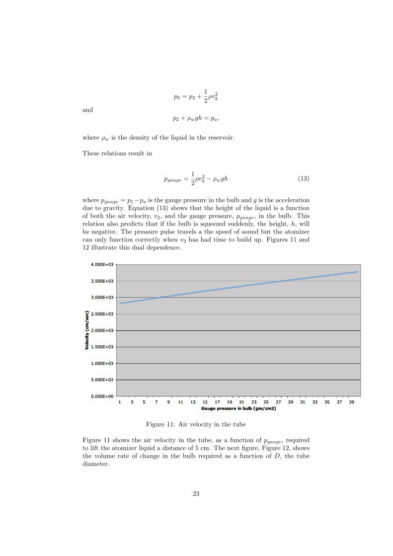
where pgauge = p1−pa is the gauge pressure in the bulb and g is the accelerationdue to gravity. Equation (13) shows that the height of the liquid is a functionof both the air velocity, v2, and the gauge pressure, pgauge, in the bulb. Thisrelation also predicts that if the bulb is squeezed suddenly, the height, h, willbe negative. The pressure pulse travels a the speed of sound but the atomizercan only function correctly when v2 has had time to build up. Figures 11 and12 illustrate this dual dependence.
Figure 11: Air velocity in the tube
Figure 11 shows the air velocity in the tube, as a function of pgauge, requiredto lift the atomizer liquid a distance of 5 cm. The next figure, Figure 12, showsthe volume rate of change in the bulb required as a function of D, the tubediameter.
23
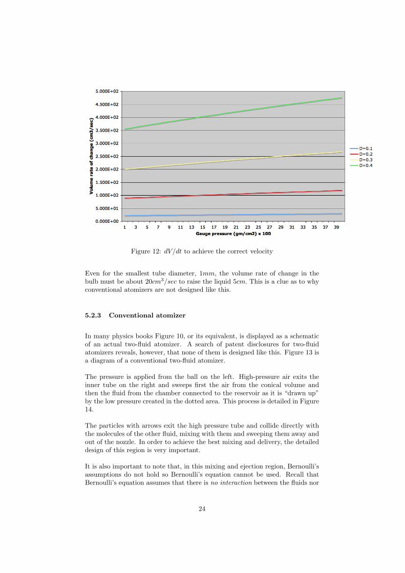
Figure 12: dV/dt to achieve the correct velocity
Even for the smallest tube diameter, 1mm, the volume rate of change in thebulb must be about 20cm3/sec to raise the liquid 5cm. This is a clue as to whyconventional atomizers are not designed like this.
5.2.3 Conventional atomizer
In many physics books Figure 10, or its equivalent, is displayed as a schematicof an actual two-fluid atomizer. A search of patent disclosures for two-fluidatomizers reveals, however, that none of them is designed like this. Figure 13 isa diagram of a conventional two-fluid atomizer.
The pressure is applied from the ball on the left. High-pressure air exits theinner tube on the right and sweeps first the air from the conical volume andthen the fluid from the chamber connected to the reservoir as it is “drawn up”by the low pressure created in the dotted area. This process is detailed in Figure14.
The particles with arrows exit the high pressure tube and collide directly withthe molecules of the other fluid, mixing with them and sweeping them away andout of the nozzle. In order to achieve the best mixing and delivery, the detaileddesign of this region is very important.
It is also important to note that, in this mixing and ejection region, Bernoulli’sassumptions do not hold so Bernoulli’s equation cannot be used. Recall thatBernoulli’s equation assumes that there is no interaction between the fluids nor
24

Figure 13: Real atomizer
Figure 14: Nozzle Detail
with the surfaces in the flow. In the case of a two-fluid atomizer, however,mixing and delivery are the two important goals.
5.2.4 Flit gun
Figure 15 is a diagram of the famous “Flit Gun” bug sprayer.
25

Figure 15: Flit Gun
The air stream exiting the gun passes over the tube and interacts with the fluidin it. First a partial vacuum is created in the tube then the liquid rises in thetube and mixes with the air exiting the pump. The angle, θ < 90◦, is crucialas are the distances, s and d. If, for example, θ ≥ 90◦, the liquid will be forcedback into the reservoir. Bernoulli’s equation does not hold for this extremelyunsteady flow.
5.2.5 Flow into an expansion chamber
Figure 16 shows an apparatus in which high-velocity air from a low pressureregion flows into a chamber at lower pressure. We refer to the sections in thefigure as Sections 1, 2, 3, 4 and a, the region under atmospheric pressure.
It is important to remember Equation (8) when thinking about the pressuresin the different sections. Bernoulli’s equation, Equation (6), does not rule outp3 < p4 in Figure 16. In fact that happens when the pressure, p1, is high enough.It may seem counterintuitive that the fluid can flow from a lower pressure intoa higher one but the forward momentum of the high velocity particles incomingfrom Section 3 is greater than that of those already in Section 4, i.e.,
(mvx)3 > (mvx)4,
and thus the particles entering win in the contest of collisions with the particlesin Section 4 and actually enter that section. In contradistinction to the situation
26

Figure 16: Restricted exit orifice
upstream where the pressures are decreasing and the interparticle interaction isnegligible, there are now many collisions between particles. In the process, theenergy of forward motion of the entering gas is in part converted into internalenergy of the gas, i.e. heat, pressure and molecular energy of vibration androtation, depending on the structure of the gas molecules. We can call thispartial thermalization because some of the kinetic energy of the molecules intranslation into Section 4 is converted to heat and internal molecular excitation,while some appears as macroscopic eddies and turbulence.
Later, in Section 9 of this paper, we will see how the temperature of the fluidflowing into a region like Section 4 of Figure 16 but with an open end to theatmosphere can cause a thrust enhancement in a rocket engine.
5.3 The Joule-Thomson effect
The above situation lies somewhere between the case of Bernoulli flow, i.e. noparticle interaction in a smoothly flowing fluid, and the behavior of a real,self-interacting gas which produces the Joule-Thomson[4] effect. In this latterregime the effects of particle collisions are of paramount importance.
Instead of Equation (6), we will use the form below for the specific energydensity as the conservation law.
1
2v2 + w = constant (14)
27

where w is the enthalpy,
w = ε+ p/ρ (15)
and ε is the thermodynamic energy per unit mass of the gas. This is the en-ergy of interatomic oscillation (in case of polyatomic gases) and rotation of themolecules as well as their potential energy due to the van der Waals forcesbetween them.
In the case that the flow velocity vanishes, v = 0, equation (14) expresses theconservation of Enthalpy. Such a case is obtained in the apparatus shown inFigure 17.
Figure 17: Joule-Thomson apparatus
In order that the thermodynamic process be adiabatic, i.e. no heat flowing inor out, the apparatus is insulated. The piston on the left provides pressure, P1
at temperature T1, and the gas moves to the chamber on the right, at pressureP2 and temperature T2 by passing through a so-called “porous plug” madeof packed granules of a chemically non-interacting substance, for example fritmade of silica. As the gas molecules bounce in chaotic fashion against eachother and the frit particles, the flow velocity is transformed into random motionand thermodynamic energy. The following quote is taken from the Wikipediaarticle on the Joule-Thomson effect:
“As a gas expands, the average distance between molecules grows. Be-cause of intermolecular attractive forces (Van der Waals forces), expansioncauses an increase in the potential energy of the gas. If no external workis extracted in the process and no heat is transferred, the total energyof the gas remains the same because of the conservation of energy. Theincrease in potential energy thus implies a decrease in kinetic energy andtherefore in temperature.
A second mechanism has the opposite effect. During gas molecule col-lisions, kinetic energy is temporarily converted into potential energy. As
28

the average intermolecular distance increases, there is a drop in the num-ber of collisions per time unit, which causes a decrease in average potentialenergy. Again, total energy is conserved, so this leads to an increase inkinetic energy (temperature). Below the Joule-Thomson inversion tem-perature, the former effect (work done internally against intermolecularattractive forces) dominates, and free expansion causes a decrease in tem-perature. Above the inversion temperature, gas molecules move fasterand so collide more often, and the latter effect (reduced collisions causinga decrease in the average potential energy) dominates: Joule-Thomsonexpansion causes a temperature increase.”[4]
A device called a “heat pump,” using an appropriate gas, can be a heater orcooler depending on how the pressures P1 and P2 are adjusted.
6 The Coanda effect
This effect, first investigated and employed by the Romanian aerodynamicsengineer Henri Marie Coanda (1886 – 1972), usually refers to the phenomenon inwhich an air flow attaches to an adjacent wall which curves away from this flow.(see [8] pp. 42, 664). Another aspect of this phenomenon is the entrainment offar from the jet (see the three panels in 5). The attachment effect is taken forgranted and it is the separation of the flow from an aerodynamic body that isdiscussed as a precursor to the stalling of the surface ([8] p. 40). The effect canbe seen in some automobile advertisements. Streamers of smoke are seen to hugthe profile of a car in a wind tunnel even as the surface of the car curves awayfrom the flow. This behavior indicates a lower pressure that aerodynamicistscall suction at that part of the surface. This is puzzling since there are nolong-distance attractive forces acting in a gas or between the gas moleculesand a surface under normal19 conditions. Figure 3 in section 4.2 discusses themechanism for suction.
6.1 Organ pipe beard
The Coanda effect is exploited in the design of large flue pipes in some pipeorgans.20 These pipes are like huge whistles and can, if they are overblown,sound the octave rather than the fundamental tone. Anyone who has playedan Irish tinwhistle knows this effect. Much of the awesome power of the grandorgan, however, comes from the volume of the bass notes. The pipe soundswhen a sheet of air is blown over the mouth. Some of this air enters the pipeand of course it must also exit. The only exit from these closed pipes is themouth itself. The exit path, then, starts at the top of the mouth of the pipe.The unwanted octave sounds when air exiting from the mouth interferes withthe wind sheet entering the pipe. How, then, to avoid this interference?
19A fluid in liquid form behaves differently.20Organ builder Bill Visscher, private communication.
29

Some organs utilize what are called beards to direct the air flowing out of thepipe away from the air entering from the air chest. A beard is a circular dowelmounted between the ears on each side of the mouth. As the air exits, it tendsto flow in the general direction of the beard but the beard is located so thatthe main flow passes over it. As the surface of the beard curves away from theflow, a low pressure is created on the top of the beard. This low pressure areaattracts the flow and keeps it from interfering with the flow entering the pipe.Figure 18 illustrates this. The precise location and size of the beard also affectthe timbre of the pipe’s sound.
Figure 18: Beard on an organ flue pipe
30

6.2 The Bunsen burner
A common application of the effect illustrated in Figure 5 is the Bunsen burner.An exploded view is shown in Figure 19 below.
Figure 19: Bunsen Burner
The effect shown in the first panel of Figure 5 is utilized in the Bunsen burnerand any other burner where the fuel and air is mixed upstream of the flame.The needle valve regulates the rate of fuel flow and the Coanda effect causes themixing as it draws in air from outside the burner.
6.3 The Coanda propelling device
Henri Coanda held many patents but perhaps the most interesting for aerody-namic design is his design of a propelling device [12]. The patent disclosure isAppendix B. The device develops lift as an enhanced buoyant force produced bydecreased pressure on the top. This decreased pressure on the curved circular
31
surface is caused by a flow of gas at high-pressure exhausting tangentially toan annular airfoil from an annular slit. In addition to enhancing the buoyantforce, the device would remove the bow wave that would hinder the motion ofthe device.
A bow wave is normally formed when an object moves through a fluid. It is easyto see the bow wave of a ship or barge. As it is propelled in the water, a shipmust push water out of the way. Because the water has mass, force is requiredto move it. By Newton’s third law, there is an equal and opposite force exertedon the ship. This effect causes drag in addition to the viscous drag of the hullof the ship as it moves through the water.
A toy helium balloon rises much more slowly than if it weren’t hindered by abow wave in the air. It is primarily the force of the bow wave that is responsiblefor the phenomenon of terminal velocity. By extending his arms and legs, askydiver can control the terminal velocity, increasing or decreasing it. Figures 1and 3 of Appendix B illustrate the dissipation of the bow wave by the Coandapropelling device.
7 Calculation of lift
Lift is caused by the collisions of fluid particles with the surface of the airfoil.By Newton’s third law, this interaction of the particles with the surface resultsin an equal and opposite reaction on the airflow itself; the particles bounce back.Say, for example, that the lift force is in the “up” direction, then the third lawforce on the air is “down.”21 The lift can be represented in two ways: 1) as thesummation of all the forces on the surface or, according to Newton’s third law,2) by the negative of the force the surface exerts on the air. The latter is theapproach that led to the Kutta-Joukowski theorem.22
Figure 20 shows a typical force configuration on the surface of an airfoil.[14] Theair flow is from the left. Note that the primary contribution to the lift is fromthe curved surface of the top of the wing. This lowered pressure, the so-calledsuction, created there also causes the Coanda effect.
The flow particles far from the airfoil’s surface “feel” this suction as a sort ofreverse bow wave and, as a result, flow toward the surface. The low pressure,maintained by the flow past the curved surface, results in a pressure gradient,∂P/∂ξ, that decreases to zero as ξ increases.23 The pressure approaches the limitp∞, the ambient pressure. ξ is the normal distance from the airfoil’s surface.
Another interesting aspect of this figure is the indication of a (conventional) bowwave of positive pressure just below the leading edge. This bow wave results in
21Here, we are only concerned with the lift force on heavier than air craft. The situation isdifferent for aerostats.
22See Reference [15] pages 236 and 237.23or more precisely the pressure gradient due to gravity
32

an upwash that moves against the main flow to join the flow above the leadingedge stagnation point. At high angles of attack this flow causes a vortex on thetop of the wing which becomes larger as the angle of attack and/or the flowvelocity increases. (See the third panel in Figure 5 above.)This vortex interfereswith the suction on top of the wing and if too large will eventually cause stall.Vortex generators, sometimes mounted on wings and control surfaces,[5] in spiteof their name, inhibit the formation of this span-wise vortex. They do this bygenerating small vortices emanating from their tips. These small vortices, forangles of attack not too large, break up the larger span-wise vortex before itforms. The axes of these vortices are in the direction of the flow.
A common stall warning device is a switch activated by a simple flap mountedon the leading edge protruding forward, which, when it gets blown upward,causes a horn in the cockpit to sound. All stall warning devices are activated,directly or indirectly by the speed of the upwash.[13] Upwash is created by theviscous interaction of the air with the lower surface of the wing. It can be seenas a stream of water from a faucet strikes a plate held at an angle to the stream.Some of the water flows upward before it finally turns and flows down the plate.If the plate is held so the stream is near the top, the upwash will actually runup and over the top of the plate. As we will see in Sections 15 and 4.7, thisupwash can be turned to advantage to increase lift.
Figure 20: Typical force configuration on an airfoil in an air flow
The total force on the wing, lift plus drag (the red arrow in Figure 20) is thevector sum:
Ftotal = −∮
airfoil
(dFn + dFs) . (2)
where
Fn is the force normal to the surface and
33

Fs is the force tangent to the surface.
The minus sign is necessary because we are calculating force on the air and useNewton’s third law to relate that to the total force, Ftotal, on the surface.
Newton’s second law is:
F = ma, (16)
or, componentwise,
Fi = mai, i = n, s. (17)
i = s denotes the component of the force and resulting acceleration along thesurface and i = n denotes the component normal to the surface.
7.1 Using Newton’s Third Law: Effects on the air causedby the presence of the airfoil
At the surface of the airfoil, the pressure exerts a force equal in magnitude andopposite in direction on the air. This pressure affects the air out to a distanceof ∆y, often many airfoil chord lengths from the surface. Newton’s second lawin differential form is
dFairfoil = −ρdsdt· dvdsdA dr (18)
where
ρ(s, r) is the air density in the volume dV = ds× dr × unit span.
ds/dt = v(s, r) = v(s, r) is the air speed,
v(s, r) is the velocity of the air,
dA is the differential surface area element,
r is the distance normal to the surface at ds.
s is the distance along the surface.
Again, the minus sign is required by Newton’s third law since we are interestedin the force on the airfoil.
34

The behavior of the air near the surface of the airfoil is very complex andchaotic but because at angles of attack less than the stall angle, this layer, theboundary layer, is very thin compared to ∆y, this complexity is not important.It is similar to the behavior in the bow wave of a boat. The water is turbulentand moving in a very complex way at the prow but some small distance awaythe water begins to smooth out into regular waves that fan out as the boatpasses. The information as to the detailed behavior in the boundary layer hasbeen lost to heat due to the viscosity of the water. The only thing that has beenpropagated over a long distance is the effect of the pressure in the boundarylayer and even this vestige of the behavior of the air near the surface will be lostat large distances from the airfoil due to viscous heating. It is this fact that hasto be ignored in the potential flow[16] approximation, e.g., the Kutta-Joukowskitheorem[10]. This theorem requires the integral called the circulation
Γ ≡∮
F · ds, (19)
be performed over a boundary far from the airfoil. Far enough, indeed, so thatthe flow there is steady. But for a real fluid there remains no effect of the airfoilafter a certain distance.
Figure 21: Geometry outside the airfoil
The presence of the surface causes shear in the air around it[18] so v 6= v∞,the flow speed far from the airfoil. (In fact on the top of the airfoil at angle ofattack, v > v∞.) That means that the flow is not steady[21] there and Bernoulli’sequation does not hold.
Integrating Equation 18 there results
Fper unit span = −∫ ∆y
surface
dr
∮
C(r)
ds ρ(s, r)v(s, r)dv
ds. (20)
35

Figure 22: Illustration of the covariant derivative.
The contour C(r) follows the surface or outside the surface, the streamlinecontour.
If the flow is not separated from the airfoil, the Coanda effect, the derivative ofv consists of two parts: ∂v/∂s and a geometric term that is the turning of thevelocity vector due to the curvature of the airfoil.24 Figure 22 illustrates this.
The dotted arrow in Figure 22 is the v(s + ∆s, r + ∆r) vector transportedparallel tail-to-tail with the v(s, r) vector so that ∆v can be calculated. Takingthe limit as ∆s→ 0, the covariant derivative of v is obtained:
∇sv = lim∆s→0
∆v
∆s=∂v
∂s+
v
R(s), (21)
where R(s) is the radius of curvature of the airfoil at ds.
We will now write the acceleration of the fluid at the surface as
a = ∇sv ·ds
dt.
We use the covariant derivative in Equation (22) below.
At the surface of the airfoil and due to its presence in the flow, the pressurecauses a force on the airfoil as well as on the air. Equation (20) then becomes
Ftotal = −∫ ∆r
surface
dr
∮
C(r)
ds ρ(s, r)v(s, r)∇sv. (22)
where24The attached velocity field is a vector bundle over the surface of the airfoil. This surface
is assumed to be a differentiable manifold. More information about differentiable manifoldscan be found in any book on Differential Geometry.
36

ρ(s, r) is the air density,
v(s, r) is the velocity of the air,
v(s, r) = ds/dt = v(s, r) is the air speed.
The presence of the surface causes shear in the air around it[18] so v(s) 6= v∞,and v∞ is the flow speed far from the airfoil. That means that the flow isnot steady[21] there and Bernoulli’s equation does not hold. This region is theboundary layer and its thickness is δ.
Notice that the circulation,
Γ ≡∮
F · ds, (19)
doesn’t arise in this derivation. In its place we have Equation (2).25 We arelooking at the effect on the air flow of the complex behavior of the air at thesurface and in the boundary layer. This effect exists as a reaction to the liftforce. Equation (22) replaces the Kutta-Joukowski theorem.
The difficulty is in evaluating the integrals in Equation (22). As has been notedabove, shear cannot be nelected. The pressure, even outside the boundary layer,is not constant. The boundary layer is defined as that space, thickness δ, justoutside the airfoil surface where
∂v(s, r)
∂r r = δ' 0
and r is in the direction normal to the airfoil.
The behavior of the air in the boundary layer may be complex but for laminarflow over a non-stalling airfoil, its behavior results just in shear and a pressuregradient. The density, ρ, is actually a function both of s and r. What valueshould be assigned ρ? We are concerned with the cause of lift, i.e., the forceson the surface of the airfoil. Our understanding is in terms of Newton’s laws.26
Figure 23 is a drawing of an airfoil that causes bending of the flow. Notice thatthe bending is not just the deflection of the air by the lower surface of the airfoil.
25The circulation would be the first term in this equation, i.e. the integral of the forcesnormal to the airfoil. Notice that this integral is a mathematical object and does not indicatethat there is a physical vortex around the airfoil. The resultant force on a buoyant objectfixed in a quiescent fluid is written the same as the circulation integral except that the integralis over the surface of the 3-dimensional object. In this case there is no flow at all.
26When Isaac Newton was asked why the apple falls as it does, he is reported to havereplied: Hypothesis non fingo! That is, “I don’t have a clue!” We don’t go any deeper thanNewton’s laws.
37

Figure 23: Bending of the airflow by an airfoil.
The flow along the top is bent also. The cause of the bending of the flow overthe top of the wing is also the cause of the Coanda effect. The behavior of theflow far from the surface of the airfoil is affected by the complex interaction ofthe surface of the airfoil with the molecules making up the flow.
The pressure at the surface of the airfoil, not the third law behavior of the flowfar from the surface, is what actually causes the lift and drag. If a method couldbe developed to compute this pressure, then lift an drag could be computed fromfirst principles.
7.2 Using Newton’s Second Law: Effects on the airfoilcaused directly by air pressure
The lift force is due to the differential in pressure between the bottom andthe top of the airfoil. If we assume that the air is approximately an ideal gas,Equations (3) and (4) show that the pressure, p, at a given temperature andthe mass density, ρ, are proportional.
First, assuming an ideal gas, notice that the mass density of the air is
ρ =nNm
V,
where
n is the number of moles of the gas in volume V ,
N ∼ 6.02× 10²³ is Avogadro’s number,
m is the mass of one particle.
This leads to,
p =ρ
Nm×RT (23)
38

where
p is the pressure,
R is the gas constant and
T is the Kelvin temperature.
Some standard methods of increasing the pressure on the bottom of the wingare angle of attack, of course, and trailing edge flaps.
But we have seen above that the most important contribution to lift, in theusual range of angles of attack, is the suction at the top of the wing. Thisdecrease in pressure as the air density is reduced is the cause of the Coandaeffect there. It is due to the decrease in ρ, the decrease in the particle densityin the boundary layer.
In a given constant volume, V, just above the surface of the wing, particlesenter and leave. Let η(s) be the particle density at s on the top of the wing.According to Equation (3) we can write
p = ηkT, (24)
where η is the particle density. We submit the following model for the particledensity in the boundary layer of a surface curving away from the main flow,
η(s) = η0=(v0
v(s)
)×Π(s). (25)
where
η(s) is the particle density at point s on the surface,
η0 is the ambient particle density,
= is a dimensionless function,
v0 is the velocity of the main flow,
v(s) is the velocity of the flow just outside the boundary layer (bl) at points on the surface and
Π(s) = Pr(scatter into bl) is the probability that a particle in the bound-ary layer will be scattered back into it.
Figure 24 depicts a portion of the curved part of the airfoil surface.
39

Figure 24: Coanda effect geometry.
The main flow is from the left. Since they are stagnant or nearly so, the par-ticles in the boundary layer, thickness δ, will be scattered. We assume that allscattering is in the direction of the main flow and all angles are equally prob-able. Those particles that are scattered into angle τ remain in the boundarylayer. The probability for a boundary layer particle to be scattered back intothe boundary layer is
Π(s) =1
π
∫ R+δ
R
τ(ξ,R(s))dξ. (26)
Figure 24 yields,
τ(ξ,R(s)) = sin−1
[R
R+ ξ
]. (27)
Combining Equations (24) through (27) there results
p(s) =η0kT
π×=
(v0
v(s)
)∫ R+δ
R
sin−1
[R(s)
R+ ξ
]dξ (28)
for the pressure on the top of the curved wing. At or near zero angle of attackthe pressure on the bottom of a flat wing is approximately ambient so the totallift force acting on the wing is
Fdirect =η0kT
π
{S−
∫
↑
[=(v0
v(s)
)∫ R+δ
R
sin−1
[R(s)
R+ ξ
]dξ
]ds
}. (29)
40

where ↑ indicates the top surface of the wing and S is the area per unit span ofthe bottom surface. Since we consider the simple case of a flat bottom surfaceparallel to the flow, the force there is just the ambient pressure times the area.The pressure on the upper surface, lowered by the action of the main flowshearing past the curved surface, is responsible for most of the lift at zero angleof attack, Φ = 0.
Figure 4 in Section 4.2 hints that the flow, v(s), over the curved surface consistsmainly of boundary layer particles activated by interaction with the main flow.The function = needs to be determined. Its form will have to do with thedetailed structure of the surface and the shape of the molecules of the flow.
8 Stalling wing
As the flow velocity increases, the secondary collisions that affect the flow par-ticles slowed by collisions with boundary layer particles cause the slowed flowparticles to be more violently knocked back toward the surface by the main flow.When they start to hit the surface itself, the forces on the surface there increase(see panel 3 in Figure 5). The wing is stalling. As the velocity increases stillfurther, the flow near27 the surface reverses itself and flows back along the wingand also increases the boundary layer population, and hence the pressure, there.The flow is said to separate at the point where the backward flow rate equalsthe forward fluid velocity. Downstream from this point, a vortex has formed.
9 Rocket engine diffuser
A rocket engine is composed of three basic parts: the pressure chamber, thethroat and the exit horn or diffuser. The following is Bernoulli’s equation appliedto the thrust of a rocket engine with no diffuser, just an exit orifice of area A:
pengine = porifice +1
2ρvexhaust
2 (30)
The thrust, then, is
Thrust = (pengine − porifice)×A = A× (1
2ρvexhaust
2). (31)
27At the surface the flow velocity is much less than the main flow velocity. The derivativeof the flow velocity in the direction normal to the surface vanishes at the so-called separationpoint on the surface. Downstream of this point the particles just above the surface are flowingin reverse of the flow.
41
The thrust is caused by the pressure, i.e., particle collisions on the side of theengine away from the throat, that is not offset by the throat pressure. It is notcaused by the mass flow rate in the exhaust. If it were confined with no exitorifice, the gas would have provided pressure offsetting that at the other end ofthe engine and the thrust would be zero in the above equation. In the absenceof a diffuser, thanks to Bernoulli’s equation, the thrust can be calculated usingthe exhaust velocity and density but these are not what cause the thrust.
The thrust of a rocket engine without diffuser is easy to calculate but is muchenhanced by the non-Bernoulli flow in the diffuser.
9.1 The diffuser
The thrust of a rocket engine is substantially increased if the exhaust gases exitinto a diffuser[8]. Diffusers are prominent in films of rocket launches and maybe examined in aeronautical museums like Le Bourget outside Paris, France. Asthe rocket exhaust exits into a parabolic chamber, it spreads to fill the entirevolume of the chamber[8] and, due to the fact that the gases in the diffuser,i.e., downstream from the orifice, are highly interacting, Bernoulli’s equation nolonger holds. A symptom of this breakdown of Bernoulli flow is that the exhaustvelocity is no longer uniform across the surfaces normal to the exhaust flow. Theexhaust spreads because of the large transverse thermal velocity components ofthe hot gases. This can be seen as a sort of transverse pressure as is measuredin a Venturi tube. Combining Equations (8) and (30) we see that just at theorifice
porifice =1
2ρ∑
(v2x + v2
y).
where the sum is over all the particles at the orifice. It is this transverse pressurethat drives the exhaust to the diffuser wall. As the hot gases collide with thediffuser wall, they produce a force normal to that surface. The shape of thediffuser is designed to provide force components in the direction of the rocket’svelocity. (See Figure 25.)
In the absence of the diffuser, the extremely energetic exhaust gases would carrymuch of their energy away. In fact, one can see this as the rocket plume spreadsbeyond the diffuser at high altitude in a sort of umbrella shape. The diffuser,then, extracts work from the gases before they exit beyond the rocket. Theanalogous situation in an internal combustion engine is to delay the openingof the exhaust valves in order to extract more work from the hot gas in thecombustion chamber.
An interesting feature of some diffusers, like those of the French Ariane rocket,is a sort of rifling on the diffuser wall. This rifling causes the gases to swirl,thus increasing the path length for the exiting particles. This keeps them in
42

Figure 25: Detail at the Diffuser Wall
contact with the wall longer allowing more of their heat energy to be convertedinto thrust.
10 The high-bypass turbofan jet engine
By the 1950s the turbojet had largely replaced the piston engine driven propelleras the main means of aircraft propulsion. The advance in the design of heat-seeking missiles, however, was becoming a serious threat to military aircraftdue to the high temperature of the jet exhaust. The thought occurred to enginedesigners that a sheath of cooler air would mask the heat signature of the jetexhaust so the heat-seeking missiles could could not “see” it. This bypassingair, however, did not only shield the exhaust but it increased dramatically theoverall efficiency of the jet engine in subsonic flight. Thus was born a truebreakthrough in jet engine design, a very useful spin-off of technology originallyintended only for military use.
Before the development of the modern high-bypass turbofan28 jet engine, therim of the entrance to the engine cowl was rather sharp. (See Figure 26.)
Modern turbofans (Figure 27) have a gently curved entrance duct. This mayseem trivial but it has the effect of greatly increasing the entrance aperture forthe turbofan due to the Coanda effect. This cowl creates a bow wave as it movesthrough the air. The presence this bow wave at subsonic speeds29 creates a flowpattern that precedes the aircraft. Examination of the third panel of Figure 5shows how the presence of a curved surface in an air flow causes what might be
28In high-bypass turbofan engines, most of the air entering the intake cowl bypasses thethe jet engine itself. This air is compressed somewhat by the shape of the entry cowl andits attendant bow-wave. The compressed air is propelled by a fan driven by a conventionalturbojet engine and then exits the cowl in an annulus at the rear.
29At supersonic speeds this effect disappears because the aircraft has outrun its bow wave.
43

Figure 26: Early turbojet
called Coanda entrainment of air from outside. This entrainment compressesthe air in front of the fan so that the fan is moving air of an increased density,ρ. This increased density and the boost in velocity provided by the fan resultsin an increase in thrust pressure p.
A similar Coanda entrainment enhances the performance of the shrouded tailrotors (Figure 28) that are used on some helicopters.[24] Figure 28 is used withthe kind permission of Burkhard Domke.30
Figure 27: The entrance cowl for an Airbus A380 turbofan engine
30http://www.b-domke.de/
44

Figure 28: Ducted fan tailrotor
11 The vortex refrigerator
A device called a vortex refrigerator consists of a cylindrical chamber into oneend of which a gas is injected tangentially. Gas is then drawn off, cold, from theaxis of the cylinder and hot from its periphery. Along the length of the cylinderthe cold molecules are separated from the hot by the vortex process outlined inFigure 6.
Figure 29: Vortex tube schematic
Figure 30: Vortex tube flow
45

The temperature of the cold air exiting from a vortex generator can be sub-stantially below that of the compressed air at the inlet.31 Although the vortexprocess described above would serve as a sort of “Maxwell’s dæmon” to separatethe cold particles from the hot there may be some other process that changesthe distribution of the particles’ energies, e.g., increases it variance. It is easy toimagine that some of the translational energy of the inlet air would be convertedinto heat of the exhausting air but it is more difficult to understand how thecold air exiting could be as much as 28◦ − 50◦ centigrade below the inlet tem-perature. Unfortunately, the measured temperature is a macroscopic quantity.It would be interesting to see if the inlet energy distribution, i.e. kinetic plusheat, is the sum of the cold and hot exhaust distributions.
The centers of hurricanes are regions of low pressure. In the great hurricane of1900 that struck Galveston, Texas, the pressure was the lowest ever recordedup to that time, 936 millibars.32 The pressure recorded in the eye of hurricaneKatrina which hit the coast of the Gulf of Mexico in 2005 was even lower thanthis at 920 millibars. If the hurricane is over water, this low pressure causesstorm surge. The water in the center of the hurricane is pushed up becauseof the low pressure there and the higher pressure outside the center. In thecase of Galveston and hurricane Katrina and most other hurricanes, this stormsurge caused most of the damage to the cities. The mechanism that causes thestructure of hurricanes and cyclones is not fully understood33 but it certainlyis a result of complex particle interactions. The flow is definitely not steady soBernoulli’s equation will not hold.
12 The Dyson Air MultiplierTM
fan
An interesting exploitation of the Coanda effect is the desk fan developed byJames Dyson.[20] In Figure 31 perhaps the most striking aspect is the lack ofvisible fan blades. Air is drawn in by an impeller in the base and is expelled athigh speed from a slot around the large annulus.
This air is directed over a curved surface shaped like an airfoil, creating a lowpressure on the inside of the annulus as shown in Figure 20 of Section (7). Figure32 shows the resultant Coanda flow.
Note that the volume rate of the air drawn in is much larger than the flow fromthe impeller in the base. Figure 33 shows a cross section of the annulus withdetail of the annular slot.
31See the websites of manufacturers of vortex refrigerators:http://www.exair.com and also http://www.airtxinternational.com
32Average standard pressure is 1013 millibars.33See the Louisiana Homeland Security website at:
http://www.ohsep.louisiana.gov/factsheets/FactsAboutHurricaneEye.htm
46
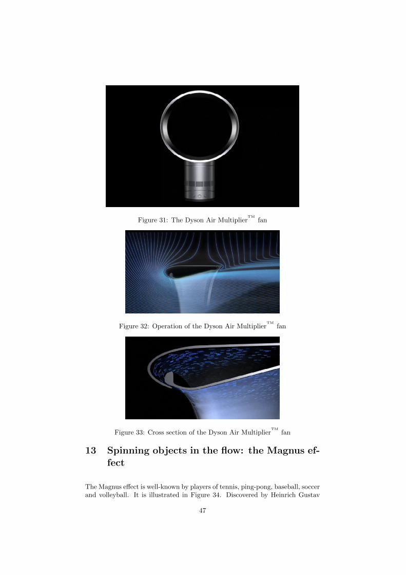
Figure 31: The Dyson Air MultiplierTM
fan
Figure 32: Operation of the Dyson Air MultiplierTM
fan
Figure 33: Cross section of the Dyson Air MultiplierTM
fan
13 Spinning objects in the flow: the Magnus ef-fect
The Magnus effect is well-known by players of tennis, ping-pong, baseball, soccerand volleyball. It is illustrated in Figure 34. Discovered by Heinrich Gustav
47
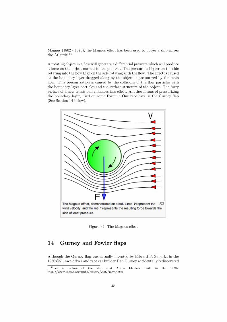
Magnus (1802 - 1870), the Magnus effect has been used to power a ship acrossthe Atlantic.34
A rotating object in a flow will generate a differential pressure which will producea force on the object normal to its spin axis. The pressure is higher on the siderotating into the flow than on the side rotating with the flow. The effect is causedas the boundary layer dragged along by the object is pressurized by the mainflow. This pressurization is caused by the collisions of the flow particles withthe boundary layer particles and the surface structure of the object. The furrysurface of a new tennis ball enhances this effect. Another means of pressurizingthe boundary layer, used on some Formula One race cars, is the Gurney flap(See Section 14 below).
Figure 34: The Magnus effect
14 Gurney and Fowler flaps
Although the Gurney flap was actually invented by Edward F. Zaparka in the1930s[27], race driver and race car builder Dan Gurney accidentally rediscovered
34See a picture of the ship that Anton Flettner built in the 1920s:http://www.tecsoc.org/pubs/history/2002/may9.htm
48

it in 1971. The height of simplicity, it is a length of aluminum angle iron boltedto the trailing edge of an airfoil. It causes an increased pressure on the sideof the airfoil from which it projects. It is easy to see that it functions as adam, trapping air from the flow, thus increasing the pressure on that side ofthe airfoil. For a race car this is done to increase the force down on the wheels,decreasing the chance for wheel spin and increasing traction for the rear wheels.Figure 35 details this simple but very effective device as used to increase lift onan airfoil.
Figure 35: Gurney flap
Ordinary Fowler flaps[28], common on commercial airliners, cause a similardamming of the flow on takeoff and landing, where maximum lift is needed.The top surface of a Fowler flap also utilizes the Coanda effect to enhance lift.“Slotted” Fowler flaps direct some of the high-pressure air under the wing overthe rear flap sections, thus enhancing the Coanda effect there.
15 Slots and slats
A slot[28] is a gap between a slat and the leading edge of a wing or between thesections of the Fowler flaps at the trailing edge.
On takeoff and landing, some airliners, in addition to Fowler flaps, use leadingedge slats and slots[28]. Designs differ from manufacturer to manufacturer buta leading edge mechanism of some kind is always incorporated into the designof the wings of airliners. Leading edge slats and slots direct the upwash fromthe bottom of the wing at angle of attack over the leading edge of the airfoil.
A simple experiment will demonstrate upwash. Hold a flat plate at a 10◦ or20◦ angle with respect to a smooth stream of water. As the water strikes it, itclimbs up the plate against the direction of the water flow. This effect is due tothe interaction of the water molecules with the microscopic protuberances onthe surface of the plate. Another way of stating this is to say that the effect isdue to the viscosity of the water.
As the slat descends into the air flowing beneath the wing, it opens a slot. (Seethe 4th panel of Figure (36.) This combination directs the upwash air smoothlyonto the top surface of the wing causing a Coanda effect there which increases
49

Figure 36: High-lift wing devices
lift. Instead of slots and slats, some Airbus planes use vortex spoilers on theleading edges of their wings. These spoilers, like slats, are deployed only ontakeoff and landing and serve to prevent a stalling vortex from forming alongthe leading edge of the wing.
16 Summary
This paper begins an investigation into how a fluid consisting of particles in-teracts with itself and with solid surfaces. Although the mathematics of fluiddynamics is beautiful, it fails to explain many mysteries that appear in the be-havior of common subsonic flows. Many Physics books, for example, attemptto explain the phenomenon of subsonic lift by using Bernoulli’s equation. Itis hoped that the brief treatment above will disabuse the reader from such anexplanation.
17 Conclusion
Anyone who has contemplated ocean waves in their magnificence or watched soli-tons marching upstream in channel flow cannot but be amazed at the beautyexhibited by the behavior of fluids, this in spite of difficulties that defy ourability to calculate their detailed behavior. It is said that the first stage of un-derstanding a phenomenon is that of its careful observation. Perhaps the nextis to attempt to formulate the behavior of the constituents of the phenomenon.Prior to the turn of the 19th century, it was believed that fluids were funda-mental entities, i.e., not composed of anything. Since Einstein’s 1905 paper
50
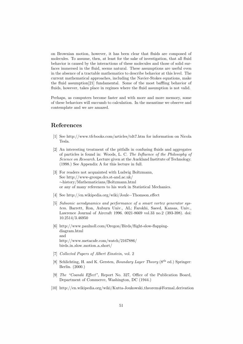
on Brownian motion, however, it has been clear that fluids are composed ofmolecules. To assume, then, at least for the sake of investigation, that all fluidbehavior is caused by the interactions of these molecules and those of solid sur-faces immersed in the fluid, seems natural. These assumptions are useful evenin the absence of a tractable mathematics to describe behavior at this level. Thecurrent mathematical approaches, including the Navier-Stokes equations, makethe fluid assumption[21] fundamental. Some of the most baffling behavior offluids, however, takes place in regimes where the fluid assumption is not valid.
Perhaps, as computers become faster and with more and more memory, someof these behaviors will succumb to calculation. In the meantime we observe andcontemplate and we are amazed.
References
[1] See http://www.tfcbooks.com/articles/tdt7.htm for information on NicolaTesla.
[2] An interesting treatment of the pitfalls in confusing fluids and aggregatesof particles is found in: Woods, L. C. The Influence of the Philosophy ofScience on Research. Lecture given at the Auckland Institute of Technology.(1998.) See Appendix A for this lecture in full.
[3] For readers not acquainted with Ludwig Boltzmann,See http://www-groups.dcs.st-and.ac.uk/∼history/Mathematicians/Boltzmann.htmlor any of many references to his work in Statistical Mechanics.
[4] See http://en.wikipedia.org/wiki/Joule−Thomson effect
[5] Subsonic aerodynamics and performance of a smart vortex generator sys-tem. Barrett, Ron, Auburn Univ., AL; Farokhi, Saeed, Kansas, Univ.,Lawrence Journal of Aircraft 1996. 0021-8669 vol.33 no.2 (393-398). doi:10.2514/3.46950
[6] http://www.paulnoll.com/Oregon/Birds/flight-slow-flapping-diagram.htmlandhttp://www.metacafe.com/watch/2167886/birds in slow motion a short/
[7] Collected Papers of Albert Einstein, vol. 2
[8] Schlichting, H. and K. Gersten, Boundary Layer Theory (8th ed.) Springer:Berlin. (2000.)
[9] The “Coanda Effect”, Report No. 327, Office of the Publication Board,Department of Commerce, Washington, DC (1944.)
[10] http://en.wikipedia.org/wiki/Kutta-Joukowski theorem#Formal derivation
51

[11] http://www.physics.thetangentbundle.net/wiki/Fluid mechanics/Kutta-Joukowski theorem
[12] USP 2,108,652 Propelling Device. See Appendix B.
[13] Denker, John S. http://www.av8n.com/how/htm/airfoils.html section 3.5
[14] See the website of Professor Martin Hepperle: http://www.mh-aerotools.de/airfoils/index.htm
[15] Anderson, John D. Jr. Introduction to Flight (3rd ed.) McGraw-Hill:NewYork. (1989.)
[16] http://en.wikipedia.org/wiki/Potential flow#Applicability and limitations
[17] Hoffman, Johan and Claes Johnson. Computational Turbulent Incompress-ible Flow. Applied Mathematics: Body and Soul 4. Springer. (2007.) ISBN:978-3-540-46531-7.
[18] Colombini, Marco. University of Genoa, Italyhttp://www.av8n.com/irro/profilo4 e.html
[19] Vortex coolers are available for sale.See http://www.newmantools.com/vortec/nema4.htmfor an assortment.
[20] http://www.dysonairmultiplier.com/
[21] Landau, L. D. and E. M. Lifshitz Fluid Dynamics (2nd ed.) (Volume 6:Course of Theoretical Physics) U.K. Pergamon. (1984.)
[22] http://www.aerospaceweb.org/question/planes/q0176.shtml
[23] H. Riedel, ”Grundzuge der Stromungsforgange beim Anlegen und Abreißeneines Flachstrahls bei der Umstromung eines Flugelprofils (Coanda-Effekt)”Deutsche Luft- und Raumfahrt Forschungsbericht 71-46 (1971.)
[24] Aerodynamic Performance Analysis of a Helicopter Shrouded Tail RotorUsing an Unstructured Mesh Flow Solver, Lee, H. D., O. J. Kwon, and J.Joo. The 5th Asian Computational Fluid Dynamics [Conference], Busan,Korea, (October 27 - 30, 2003.)
[25] Working Model allows the programming of 2D kinematic models. Seehttp://www.design-simulation.com/
[26] Senior thesis of Jacob Vianni, University of California, Santa Cruz. (2006.)
[27] See the interesting article:http://www.allamericanracers.com/gurney flap.html
[28] See http://www.centennialofflight.gov/essay/Theories of Flight/Devices/TH17G5.htm
A On the consideration of fluids at the particlelevel
52

The Influence of the Philosophyof Science on Research
L.C. Woods
(Balliol College, University of Oxford)
Lecture delivered at the Auckland Institute of Technologyon Friday, 7th August, 1998.
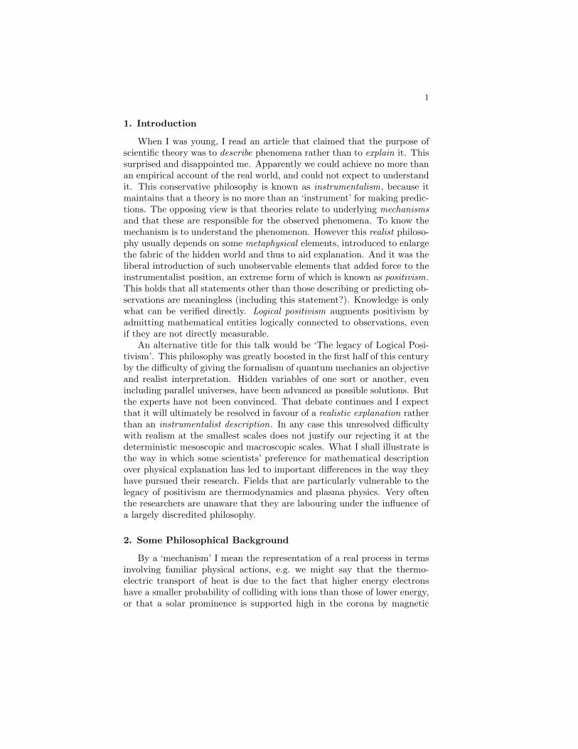
1
1. Introduction
When I was young, I read an article that claimed that the purpose ofscientific theory was to describe phenomena rather than to explain it. Thissurprised and disappointed me. Apparently we could achieve no more thanan empirical account of the real world, and could not expect to understandit. This conservative philosophy is known as instrumentalism, because itmaintains that a theory is no more than an ‘instrument’ for making predic-tions. The opposing view is that theories relate to underlying mechanismsand that these are responsible for the observed phenomena. To know themechanism is to understand the phenomenon. However this realist philoso-phy usually depends on some metaphysical elements, introduced to enlargethe fabric of the hidden world and thus to aid explanation. And it was theliberal introduction of such unobservable elements that added force to theinstrumentalist position, an extreme form of which is known as positivism.This holds that all statements other than those describing or predicting ob-servations are meaningless (including this statement?). Knowledge is onlywhat can be verified directly. Logical positivism augments positivism byadmitting mathematical entities logically connected to observations, evenif they are not directly measurable.
An alternative title for this talk would be ‘The legacy of Logical Posi-tivism’. This philosophy was greatly boosted in the first half of this centuryby the difficulty of giving the formalism of quantum mechanics an objectiveand realist interpretation. Hidden variables of one sort or another, evenincluding parallel universes, have been advanced as possible solutions. Butthe experts have not been convinced. That debate continues and I expectthat it will ultimately be resolved in favour of a realistic explanation ratherthan an instrumentalist description. In any case this unresolved difficultywith realism at the smallest scales does not justify our rejecting it at thedeterministic mesoscopic and macroscopic scales. What I shall illustrate isthe way in which some scientists’ preference for mathematical descriptionover physical explanation has led to important differences in the way theyhave pursued their research. Fields that are particularly vulnerable to thelegacy of positivism are thermodynamics and plasma physics. Very oftenthe researchers are unaware that they are labouring under the influence ofa largely discredited philosophy.
2. Some Philosophical Background
By a ‘mechanism’ I mean the representation of a real process in termsinvolving familiar physical actions, e.g. we might say that the thermo-electric transport of heat is due to the fact that higher energy electronshave a smaller probability of colliding with ions than those of lower energy,or that a solar prominence is supported high in the corona by magnetic
2
forces. Once we have the mechanism identified, fitting it out with suitablemathematics is often the easier task. In specifying a mechanism, the firstobjective is to try to identify those features essential to the phenomenonunder consideration. Elaboration of the model can follow when the min-imalist position has proved itself. But it may be necessary to add someunobservable structure to the mechanism from the outset, e.g. the mag-netic field lying out-of-sight well below the photosphere when modelling asunspot structure.
Ockham was a 14th-century, Scholastic philosopher, who attacked thesupremacy of Papal power. His ‘razor’ was the statement that entitiesare not to be multiplied beyond necessity. In a similar vein, Ernst Mach(1838–1916) stated that ‘it is the aim of science to present the facts ofnature in the simplest and most economic conceptual formulations’. Thiswas a reaction against the metaphysical extravagances of the 17th and 18thcenturies, during which, inter alia, various fluids were adduced to ‘explain’physical phenomena. A classical case was the chemists’ phlogiston that,having negative weight, supposedly explained the increase in mass due toburning—the heat drove off the phlogiston. Oxygen was yet to be discov-ered. Heat had the properties of an indestructible fluid called ‘caloric’;electricity was said to be composed of two fluids, with no more evidencethan this seemed to provide an explanation of some observations. Butnowadays we do talk of electron and ion fluids. Also Carnot managed toestablish the principle that later evolved into the second law of thermody-namics, by employing the caloric concept. (It was the first law that laterdestroyed the conservation of caloric.) So some metaphysical inventionsprove to be closer to the truth than at first imagined. Such elements evolvefrom being metaphysical to eventually being considered to be ‘real’.
Atoms were ruled out by Mach and other anti-atomists of his day. Theycould not be observed, so were not real. They could be admitted only asa device to give economy of thought. Realists are much bolder, willing tointroduce unobserved elements and to take them as being real, in order toprovide ‘explanations’. A classic example is William Harvey’s (1578-1657)explanation of the circulation of the blood and the function of the heartas a pump. Although he had no microscope to see the capillary vesselsconnecting the arterial and venous systems, he maintained from evidenceimplying a circulation that they must exist. Pauli’s (1930) invention ofthe neutrino to ensure the conservation of energy and momentum duringbeta decay is another good example of a bold metaphysical creation. Itwas not until powerful nuclear reactors were available that the existence ofneutrinos could be confirmed.
Analogy is a powerful, heuristic means of arriving at a possible descrip-tion of a new phenomenon. It may be a mathematical likeness only, as withthe fact that the temperature in steady-state heat flux and the gravitationpotential both satisfy Laplace’s equation, or it can be a deeper physical

3
analogy, such as that between the transport of heat by colliding particlesand its transport by photons within the Sun. For example Einstein’s inter-pretation of Brownian motion as being due to the uneven bombardment ofmicroscopic particles by molecules may have taken root in his mind froman obvious macroscopic analogy, and its success led quickly to the full ac-ceptance of the reality of molecules. Metaphysical inventions have a centralrole in science, provided one always remembers that they are on ‘trial’ untilthe indirect evidence is so strong that they can be considered to be ‘real’.
Maxwell was pre-eminent in his use of analogy. He deployed it in twofamous examples. First in his kinetic theory of gases he used a ‘billiard-ball’ model to describe the trajectories of the molecules. This was excellentfor monatomic molecules, but partially failed with diatomic molecules forreasons that are now obvious to us. His other great analogy was to representmagnetic fields as vortex filaments in a ‘fluid’, and to separate them byparticles each revolving on its own axis in the opposite direction from thatof the vortices. These ‘idle-wheels’ (later identified as ‘electrons’) were toallow the free rotation of the vortex filaments. To cap it all, he gave thevortices elastic properties to represent the displacement current! In thismanner he arrived at his set of equations for the electromagnetic field. Hefound that the velocity with which disturbances propagated through hissystem of vortices and particles (70,843 leagues per sec.) agreed so closelywith Fizeau’s value for the speed of light that he remarked “we can scarcelyavoid the inference that light consists in the transverse modulations of thesame medium which is the cause of electric and magnetic phenomena”.
Then the mechanical description was abandoned, it being assumed thatthe equations alone now represented the phenomenon. Maxwell’s analogy,however absurd it seems today, led him to the greatest discovery of the19th century, namely that light was electromagnetic in nature. The Frenchpositivist, Pierre Duhem, observed sarcastically that Maxwell had cheatedby falsifying one of the equations of elasticity in order to obtain a resultthat he already knew by other means.
However if one asserts the whole theory is simply the equations, oneis adopting a positivist point of view. It is Faraday’s great metaphysicalconstruction—the notion of an electromagnetic field permeating space—that allows a return to a physical description of Maxwell’s equations. Thiscontinuum picture is very helpful in trying to understand the interaction offields and particles. I shall use ‘mechanism’ in this extended sense in whatfollows.
Since logical positivists eschew physical mechanisms, they are attractedto mathematical treatments, especially when an axiomatic basis can beadopted or devised to give the approach the gloss of pure mathematics.The belief that, excepting blunders, mathematical proofs are absolutelycertain and therefore superior to physical arguments, should have beendealt the coup de grace by Godel’s incompleteness theorem. This states

4
that if a set of rules of inference in a branch of mathematics is consistent,then within that branch there must exist valid methods of proof that theserules fail to identify as valid.
Of course the equations of mathematical physics follow from the as-sumed mechanisms, but sometimes this dependence is inverted or forgottenand the equations begin to assume an independent significance well beyondtheir original range of validity. This does not seem to concern cosmologists,whose big bang, in which the universe is created from nothing via a quan-tum mechanical tunnelling process, is a wild, but apparently successful,extrapolation of known physical laws.
The importance of imagining phenomena in terms of mechanisms ratherthan the equations employed to represent them, is that mechanisms are of-ten much more suggestive of modifications and extensions to more accuratemodels of the processes, whereas equations, especially if they are compli-cated as in the integro-differential equation of kinetic theory, or as in thefull set of MHD equations, are less helpful. Equations sometimes havemany terms, each of which usually represents a distinct physical process.It is important to try to relate the terms individually to features of thephysical model and not simply to lump them together.
Phenomena in fields like biology, where the mechanisms are obscure orunknown, and which rely on statistical data to suggest causal connections,remain fertile for the positivists. To be true to their philosophy, they wouldbe content to rest the case for the dangers of cigarette smoking on thecorrelation discovered between smoking and various types of illness. Butthe merchants of death are realists. The cigarette manufacturers insistedthat, in the absence of proven biological mechanisms relating disease tosmoking, their product was innocent. It is true that mere correlation provesnothing, a classical case being the noted correlation between the incidenceof prostitution in London just after the second World War and the salaryof Bishops.
3. How Positivists Confused the Basis of Plasma Physics
Whether or not the early plasma physicists knew any philosophy ofscience I cannot tell, but it would appear from their mistakes that theypreferred formal mathematics to physical mechanisms. The most obviousexample is that plasma pressure was defined as momentum flux , which iscorrect only if molecular collisions are sufficiently numerous. The classicalcase of wall pressure being due to its bombardment by molecules shouldhave made the role of collisions obvious enough, but the momentum fluxdefinition, in which the collisions are only implicit , confused quite experi-enced scientists into believing that there could be pressure gradients evenin a collisionless plasma. One wonders by what mechanism can purelyballistic particles transmit a pressure force.

5
I was once challenged at a seminar I was giving at the UK CulhamLaboratory for Fusion Research. A scientist claimed that ‘Collisions are notessential for there to be a pressure gradient in a plasma!’ His argumentwas that one could have a gradient in the number density, n, of ionisedparticles, maintained by a strong magnetic field (which is correct) and ifthe medium were isothermal, from the law p ∝ nT relating the pressureto the temperature T , it follows that there would be a gradient in thepressure. It seemed plausible to the audience. They had become so familiarwith the classical pressure/temperature law that they had forgotten that itsderivation required collisions, i.e. it is not true that p ∝ nT in a collisionlessplasma. One could take it to be a definition, but then it would have nophysical content.
Although this mistake seems harmless enough, it was compounded intoa more ridiculous and even dangerous notion for a plasma in a strongmagnetic field. If the magnetic field strength B say, has a gradient in adirection orthogonal to the field vector B, as the charged particles gyrateabout the field lines with a radius inversely proportional to B, the variationin the radius of gyration experienced by the particles causes them to driftin a direction orthogonal to both B and its gradient. (The motion hasa similarity to that of a top on an inclined plane—the gravitational forcedown the plane results in a motion of the top along the plane at rightangles to this force.) This is known as ‘grad B drift’ and depends on theassumption that the average time interval τ between successive particlecollisions is much greater the gyration time, ω−1
c . The individual particleshave an average velocity uB across the field determined by the value ofgrad B.
Now consider the whole collection of particles treated as being a fluid .The equation of fluid motion does not have a term involving grad B, butit does have a term proportional to the pressure gradient, which gives riseto a fluid velocity v across the field lines depending on the magnitude ofgrad p. Now the fun begins. The average drift velocity uB it would seem,cannot possibly be the same as v, since the former depends only on gradB and the latter only on grad p. This means that, with appropriate choiceof the two gradients, it is possible to send the ion mass qua particles inthe opposite direction to the ion mass qua fluid . But there can be onlyone direction of mass motion. The amazing thing is that this reputed‘paradox’ is acknowledged and accepted in the literature. That there mustbe an error is not even appreciated. The simple mistake is to assume thatin the guiding centre description the particles are collisionless, but in thefluid description they respond to pressure forces, i.e. to the impact of otherparticles.
Why do I think this confusion over pressure is serious? Well the ex-tremely expensive and unsuccessful fusion energy project, in which veryhot plasma was supposed to be confined by magnetic fields, was based on

6
theory in which guiding centre motion plays a role. And the (incorrect)equations resulting from not understanding the nature of plasma pressurefailed to reveal that there would be a disastrous loss of plasma across thetokamak fields. But the error goes deeper than that. The basic equationon which all of the kinetic theory of plasmas was developed is Boltzmann’skinetic equation, which we shall next consider.
4. Why Boltzmann’s Equation is Incorrect
In 1872 Boltzmann published the paper “Further Studies on the Ther-mal Equilibrium of Gas Molecules” that contains his famous integro-differential equation for the evolution of the density of particles in phasespace. At a meeting in Vienna to commemorate the centenary of this pub-lication, G.E.Uhlenbeck stated:
‘The Boltzmann equation has become such a generally accepted and centralpart of statistical mechanics, that it almost seems blasphemy to questionits validity and to seek out its limitations. It is also almost a miracle howthe equation has withstood all criticisms...’
However, that there is an important limitation to the equation becomesevident when terms second-order in the ratio of the microscopic (molecularcollisional) time-scale to the macroscopic time-scale, known as the Knudsennumber , are examined. (A typical second-order term involves two gradi-ents, e.g. the heat flux includes a term q2 = −α∇v ·∇T , where α is aconstant and v is the fluid velocity. The first-order theory yields the clas-sical transport equations of Fourier, Ohm and Newton and is correct.) Forexample there are physically evident terms for the heat flux across mag-netic fields that cannot be derived from Boltzmann’s equation. On theother hand, his equation leads to second-order terms for heat transport inan isothermal neutral gas, in which circumstances no such transport is pos-sible. One such term has ∇p in place of ∇T in the (correct) second-orderexpression for q2 just quoted. The physical nature of energy transport ina non-conducting gas must depend on there being a temperature gradient.
The fault with the equation lies with the assumption that the collisionrate between molecules is proportional to the product of the distributionfunctions of the colliding particles, regardless of anisotropies generated bythe presence of pressure gradients and fluid shear. Boltzmann’s main pur-pose was to find a way of deducing the second law of thermodynamics frommechanics and also to improve on Maxwell’s derivation of the equilibriumdistribution. In this he certainly succeeded. In fact only seven of the 96pages of his paper deal with the calculation of the transport properties ofgases. The tacit assumption that the equation was valid over a wide rangeof Knudsen numbers, made by Chapman, Enskog and many others since,is where the fault really lies.

7
In the formulation of the kinetic equation, the distinction between con-vection and diffusion is not correctly drawn. Diffusion is due to molecularagitation superimposed on a reference frame that not only has the speed ofthe fluid element, but which also accelerates and spins with it. This meansthat the pressure gradient must be assumed known from the outset, sincethe fluid element to which the frame is attached, is accelerated by this force.The spurious terms in the heat transport mentioned above, arise becauseof the neglect of these fluid accelerations. For example, scattering is takenwithout comment to be isotropic in a frame that has the velocity of a fluidelement, but not its acceleration. Had the mechanism on which the equa-tion was based, namely the collisional scattering of molecules in and outof a fully convected element of phase-space, been clearly understood andkept in mind, the error would have been soon discovered and the originalBoltzmann’s equation corrected for higher values of the Knudsen number.
Great sums and scientific effort have been invested into finding com-puter solutions of Boltzmann’s equation in the regime of large Knudsennumbers. Such a waste and just because of the apparently unshakeablebelief in equations rather than mechanisms. So far as research in fusion en-ergy is concerned, the cost of the failed tokamak machine world-wide mustexceed ten billion dollars. At least in part this waste can be attributedto the propensity of plasma physicists to adopt a positivistic view of theirscience.
5. Understanding Entropy
My final example of the legacy of positivism comes from that will-o’-the-wisp known as entropy . What is curious about this property of macroscopicsystems is that it is a purely defined quantity, not relating to a physicalproperty until precise details of the state of the system have been specified.And the problem with ‘state’ is that it is observer-dependent , i.e. it dependson what elements the observer wishes to include in his physical model ofthe system under consideration. The greater the detail, the smaller theresulting entropy of the system. In this case the ‘mechanism’ is simply thechosen physical state. Unfortunately the positivist position seems to bethat entropy is a property of systems, independent of the observer—themechanism via state is quite ignored. Examples of this are to be found ina subject optimistically termed ‘rational thermodynamics’, in which tem-perature and entropy are taken to be ‘primitive’ quantities not requiringdefinition.
This ignorance would be harmless enough, except that ‘the’ entropy,or rather its rate of production, σ say, is made the basis for determiningthe form of constitutive relations, namely the laws relating fluxes and thethermodynamic forces driving them. The principle is that these fluxes andforces appear as quadratic products in σ, which it is assumed must always

8
be positive. The second law of thermodynamics is claimed to support thisview. Fourier’s law relating the heat flux q to the temperature gradient∇T , is a simple example. In the absence of other processes, the productionrate is σ = −q ·∇T > 0, which implies that q = −κ∇T , where κ is a pos-itive constant termed the ‘thermal conductivity’. The physical mechanismthat generates these fluxes and that is responsible for σ generally beingpositive is lost in a pseudo-mathematical haze, with the hope no doubtthat the pure mathematical appearance of the formalism will impress thefollowers into believing that the reasoning is unassailable.
Of course this approach leads to gross errors, perhaps the simplest ofwhich is a theorem due to Coleman that asserts the entropy to be inde-pendent of the gradients of temperature and fluid velocity. In a theorycorrect to second-order in the Knudsen number, this is readily shown tobe wrong. Another evident error arises in the theory of heat flux acrossstrong magnetic fields. There is an interesting and very important term q∧
that happens to be orthogonal to both the temperature gradient and themagnetic field. Since q∧ · ∇T = 0, this term does not generate entropy anddoes not appear in the expression for σ. It therefore does not exist for therational thermodynamicist. In fact it is the second-order form of q∧ that isresponsible for the failure of tokamaks to retain their energy for more thana few seconds at best, when minutes would be required for an economicfusion reactor. And the same transport equation plays a dominant role incoronal physics.
The entropy production rate is assumed to be always positive. This ispresented as an axiom, with the second law as justification. Unfortunatelythe second law gives no guarantee that σ is always positive. In a strongmagnetic field it is in fact the case that σ may have either sign. Theargument is as follows. We expand σ as a power series in the Knudsennumber, ε say,
σ ≈ σ1 + σ2,(σi = O(εi)
),
where we have carried the expansion only to the second-order term. Ofthe two terms, only σ1 is dissipative. It is therefore always positive. Thesecond-order term has three gradients and is consequently reversible, i.e.it may have either sign. Moreover it can be much larger than σ1, in whichcase the total σ may be negative. This is not a failure of the second law,which relates only to dissipative terms. The problem is that the rationalthermodynamicist has adopted an axiom, the physical content of which hedoes not understand.
It can be shown that the stability of a continuum flow requires that
σ1 ≥ 0, σ1 + σ2 ≥ 0 ,
the inequalities in which have different roles. The first determines that thethermal conductivity and the fluid viscosity be positive quantities, mak-ing it a thermodynamic constraint; it is universal and independent of the
9
actual flows obtained. The coefficients of the second-order terms, beingdetermined by the same molecular behaviour as the first-order coefficients,are closely related to them, leaving no freedom for further thermodynamicconstraints to be satisfied.
On the other hand the stability constraint ((σ1 + σ2) ≥ 0) can besatisfied only by restricting the class of fluid flows. It sets a limit on thegradients, or equivalently on the Knudsen number making it a macroscopicor fluid constraint. Provided ε is sufficiently small—certainly less thanunity—σ1 will be larger than |σ2| and the constraint will be satisfied. Wemight imagine some initial state, with steep gradients, for which this doesnot hold. The fluid flow may be momentarily unstable, but the resultingfluctuation will quickly restore a new equilibrium state, in which σ2 is eitherpositive, or smaller in magnitude than σ1.
Since the second law of thermodynamics is not normally associated withthe question of the stability or not of the flow field, it is restricted to thethermodynamic constraint, σ1 ≥ 0, while the constraint on (σ1 + σ2) isconcerned solely with the macroscopic stability of the flow field. Certainlywith magnetoplasmas, even with convergent Knudsen number expansions,the O(ε2) terms dominate the classical O(ε) terms by orders of magnitudeand instabilities in which (σ1 +σ2) changes sign periodically do occur. Theadoption of the inequality σ > 0 as an axiom is a serious mistake.
6. Conclusions
I have tried to show that the attitude of scientists to their research—the way they go about it—is greatly influenced by the beliefs they haveadopted, consciously or otherwise, about the nature of the scientific enter-prise. In this way, the philosophy of science does play an important, butindirect role in research, a point of view that would have been quite obviousto most 19th Century scientists. The importance of philosophical concernsin cosmology and quantum physics, in which branches of science there isno shortage of metaphysical invention, is obvious enough, but that thisextends into the classical realms of continuum physics is not sufficientlyappreciated.
University teaching is largely responsible for the inculcation of positivistattitudes in the typical university graduate. Mathematical approaches tophysics and the mathematical sciences are easier to teach and easier tolearn. Mechanisms are not ignored, but they are given less attention, espe-cially where it counts for the average student, namely in the examinationroom. When I was an examiner for Oxford Finals in Mathematics, I al-ways attempted to set some questions essay-type discussions of underlyingphysical principles. But these were seldom answered—they were thoughtto be too difficult and in any case how can one get high marks for a mereessay!

B Henri Coanda’s Propelling Device
63


