aerodynamic study of go-kart nose cones me450 introduction to computer aided engineering becker, joe...
TRANSCRIPT

Aerodynamic Study ofAerodynamic Study ofGo-kart Nose ConesGo-kart Nose Cones
ME450 Introduction to Computer ME450 Introduction to Computer Aided EngineeringAided Engineering
Becker, JoeBecker, Joe
Professor H. U. AkayProfessor H. U. Akay
May 1, 2000May 1, 2000

Example of Enduro Type Go-kartExample of Enduro Type Go-kart Driver lays on his\her backDriver lays on his\her back Race on road courses such Race on road courses such
as Mid-Ohioas Mid-Ohio Speeds are in excess of 80 Speeds are in excess of 80
mph (35.76 m/s)mph (35.76 m/s)

Project ObjectiveProject Objective
Use Finite Element Code (ANSYS: CFD Use Finite Element Code (ANSYS: CFD component FLOTRAN) for the followingcomponent FLOTRAN) for the following– Comparison of two nose cone shapes to Comparison of two nose cone shapes to
determine which is more aerodynamicdetermine which is more aerodynamic– Comparison of two meshing techniquesComparison of two meshing techniques
» Mapped Mesh (Structured Mesh)Mapped Mesh (Structured Mesh)
» Free MeshFree Mesh

Theory: AssumptionsTheory: Assumptions
Steady StateSteady State Newtonian FluidNewtonian Fluid No-slip at Fluid\Solid No-slip at Fluid\Solid
InterfaceInterface TurbulentTurbulent IncompressibleIncompressible IsothermalIsothermal
Property Value Units
Density 1.205 kg/m3
Dynamic Viscosity 1.81E-05 Ns/m2
Characteristic Length 2.44 mFree Stream Velocity 35.76 m/s
Reynolds Number 5.80E+06
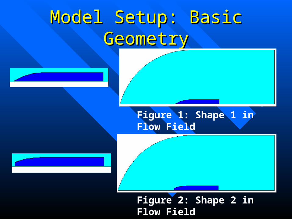
Model Setup: Basic GeometryModel Setup: Basic Geometry
Figure 1: Shape 1 in Flow Field
Figure 2: Shape 2 in Flow Field

Basic Geometry ComparisonBasic Geometry Comparison
Similarities Differences
Kart Length 8' (2.43 m) Upper surface of kart between leading
Inlet Length 10' (3.05 m) edge and 32" (0.813 m) from leading edge
Outlet Length 10' (3.05 m) Upper surface of flow field between leading
Min. Flow Height 9' (2.74 m) edge and 12.7' (3.861 m) from leading edge

ANSYS ProcedureANSYS Procedure
Define Keypoints and Create LinesDefine Keypoints and Create Lines Make Areas from Line LoopsMake Areas from Line Loops Mesh AreasMesh Areas Set Boundary ConditionsSet Boundary Conditions Set Solver ParametersSet Solver Parameters Solve FLOTRANSolve FLOTRAN

Shape 1: AreasShape 1: Areas

Shape 2: AreasShape 2: Areas

Mapped MeshesMapped Meshes
Shape 1 Mapped Mesh
Shape 2 Mapped Mesh

Free MeshesFree Meshes
Shape 1 Free Mesh
Shape 2 Free Mesh
Boundary ConditionsBoundary Conditions
All Boundary Conditions were applied to All Boundary Conditions were applied to lineslines
Velocity of 0 m/s applied to ground and all Velocity of 0 m/s applied to ground and all surfaces of kartsurfaces of kart
Velocity of 35.76 m/s in x-direction applied Velocity of 35.76 m/s in x-direction applied to the upper free stream surfaceto the upper free stream surface
Relative Pressure of 0 Pa applied to “outlet”Relative Pressure of 0 Pa applied to “outlet”

FLOTRAN ParametersFLOTRAN Parameters
Steady-state with turbulent solverSteady-state with turbulent solver Fluid properties set to air in standard SIFluid properties set to air in standard SI Solver set to perform 250 iterationsSolver set to perform 250 iterations

ResultsResults

Shape 1 Velocity (m/s)Shape 1 Velocity (m/s)
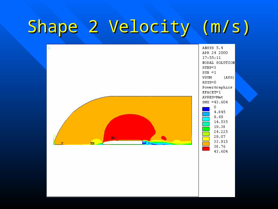
Shape 2 Velocity (m/s)Shape 2 Velocity (m/s)

Shape 1 Pressure (Pa)Shape 1 Pressure (Pa)

Shape 2 Pressure (Pa)Shape 2 Pressure (Pa)

Shape 1 Turbulent KE (J)Shape 1 Turbulent KE (J)

Shape 2 Turbulent KE (J)Shape 2 Turbulent KE (J)

Shape 1 Free Mesh ResultsShape 1 Free Mesh Results
Shape 1 Velocity (m/s) Shape 1 Pressure (Pa)
Shape 1 Turbulent KE (J)

Shape 2 Free Mesh ResultsShape 2 Free Mesh Results
Shape 2 Velocity (m/s) Shape 2 Pressure (Pa)
Shape 2 Turbulent KE (J)

ConclusionConclusion
Shape 1 is better than Shape 2Shape 1 is better than Shape 2 A mapped mesh is slightly better than a free A mapped mesh is slightly better than a free
meshmesh Results are only as good as the mesh that Results are only as good as the mesh that
they arise fromthey arise from

I AM DONE!I AM DONE!