aerodynamic structural design studies of low-sweep
TRANSCRIPT

Aerodynamic–Structural Design Studiesof Low-Sweep Transonic Wings
Antony Jameson∗
Stanford University, Stanford, California 94305-3030
John C. Vassberg†
Hydro-Aero Consulting Group, Long Beach, California 90803
and
Sriram Shankaran‡
Intelligent Aerodynamics, Menlo Park, California 94325
DOI: 10.2514/1.42775
The current generation ofwing designs for civilian air transport typically have a sweptwing.However, thesewings
were designed without the aid of modern high-fidelity simulation and multidisciplinary optimization tools. With
rapid advances in numerical simulation of high-Reynolds-numberflows and efficient shape-optimization techniques,
it is now possible to revisit the designs of modern commercial wide-body aircraft to quantitatively and qualitatively
determine the sweep of transonic wings. Results from the aerodynamic shape optimization of a low-sweep wing of a
modern transonic civil transport aircraft shows that it is possible to delay the drag rise of this wing to beyondMach
Number of 0.8 if the sections are redesigned. It is conceivable that future aircraft designswill be governed by the need
to deliver improved performancewith reduced fuel consumption. In this study,we systematically study the feasibility
of designing wings with low sweep without aerodynamic or structural performance penalties. The study presented
here explores the possibility of extending some commonly accepted limits related to the general layout of an efficient
transonic wing. Specifically, the Mach–sweep–thickness relationships are revisited at a cursory level. Pure
aerodynamic optimization ofwingswith varying sweeps (5 to 35 degrees) shows that the design space is relatively flat.
These optimized configurations are then studied using an aerostructural optimization package along with planform
variations. The aerostructural optimization reveals that the design space is again relatively flat, confirming the
assumption that wings with low sweep can be effectively used as an alternative to current sweptback configurations.
The results obtained from the optimization studies show that it may be possible to significantly reduce wing sweep
without incurring either aerodynamic or structural penalties, especially for M � 0:8 aircraft designs.
Nomenclature
Ar = wing aspect ratiob = wing spanC = wing chordCD = drag coefficientCW = wing weight coefficientE��� = Young’s modulusL=D = lift-to-drag ratioM = Mach numberpd = target/design pressureR = rangeSref = reference areaT = wing thicknessu, fj = displacement, force fieldW1 = takeoff weightW2 = landing weight� = penalty for constraint violation�i = relative Pareto weights� = wing sweep� = wing taper
� = density of the material� = stress on the material
I. Introduction
T HE current generation of civilian transport aircraft are typicallydesigned with a moderately-high-swept wing. However, the
planform layouts of these wings were substantially influenced byhistorical design charts developed decades ago. These design chartswere derived and updated from wind-tunnel and flight data collectedover the years; they include shifts due to technology levels, such asthat introduced by supercritical airfoil sections. Most of the winggeometries that form the basis of these data were designed using cut-and-trymethods and augmentedwith parametric variations of sweep,thickness, lifting condition, and freestream Mach number. Moreimportant, this knowledge basewas predominantly developed beforethe advent of modern high-fidelity simulation capabilities andmultidisciplinary optimization tools. With rapid advances in thenumerical simulation of high-Reynolds-number flows and efficientshape-optimization techniques, it is now feasible to revisit thegeneral layout drivers of transonic-wing planforms for the benefit offuture commercial transport aircraft. Specifically, it may be currentlypossible to extend the accepted bounding limit of the Mach–sweep–thickness (M�T) relationships. Recent results from an aerodynamicshape optimization of a low-sweep wing of a modern transonictransport have shown that it is possible to delay the drag rise of thiswing to beyond a Mach number of 0.8.
Driven by escalating fuel costs as well as by environmentalconcerns, it is highly likely that future aircraft designs will bedirected to deliver improved performance with significantly reducedfuel burn per passenger mile, even if it incurs a modest increase inmission block time. For example, a sweet spot in the aircraft designspace may exist nearM� 0:8, where an unducted-fan engine could
Presented as Paper 0145 at the 46th Aerospace Sciences Meeting andExhibit, Reno, NV, 7–10 January 2008; received 16 December 2008;accepted for publication 16 January 2010. Copyright © 2010 by the authors.Published by the American Institute of Aeronautics and Astronautics, Inc.,with permission. Copies of this paper may be made for personal or internaluse, on condition that the copier pay the $10.00 per-copy fee to the CopyrightClearance Center, Inc., 222 Rosewood Drive, Danvers, MA 01923; includethe code 0021-8669/10 and $10.00 in correspondence with the CCC.
∗Thomas V. Jones Professor of Engineering, Department of Aeronauticsand Astronautics. Fellow AIAA.
†Boeing Technical Fellow. Fellow AIAA.‡Technology Philanthropist.
JOURNAL OF AIRCRAFT
Vol. 47, No. 2, March–April 2010
505

be used, thus yielding large reductions in specific fuel consumption.If it is possible to develop an efficient low-sweep wing capableof M� 0:8 cruise, then other synergies such as reductions inmanufacturing costs could also be exploited.
In this work, we systematically study the feasibility of designingwings with reduced sweep without incurring aerodynamic or struc-tural performance penalties. Pure aerodynamic optimizations oftransonic wings with varying sweeps (5� � � � 35�) show that theM�T design spacemay be relativelyflat with respect toML=D, thusyielding higher range factors at reduced cruiseMach numbers. Theseaerodynamically optimized configurations were further studiedusing an aerodynamic–structural optimization package along withplanform variations. The aerodynamic–structural optimizationsreveal that theM�T design space remains relatively flat with respecttoML=D and operator emptyweight, thus confirming the conclusionthat wings with low sweep can be effectively used as an alternative tocurrent higher-sweep configurations.
II. Approach
The approach taken in this study is organized into two phases. Inthe first phase, pure aerodynamic optimizations were conducted on aparametric variation of wing sweep while holding structural beamproperties (lengths and depths) of the exposed wing constant. In the
second phase, the aerodynamically optimal wings from the initialphase were reoptimized with a coupled aerodynamic–structuralmethod.
A. Geometry Setup
To establish a consistent set of seed geometries of varying sweep, abaseline wing/body configuration that is typical of current aircraft-design practices was used. This baseline wing/body configurationwas developed to cruise efficiently at a Mach number of M � 0:85and a lift coefficient of CL � 0:5; its planform (with definingstations) is depicted in Fig. 1. Figure 2 shows its nondimensionalthickness max -T=C (left) and corresponding absolute thicknessmax -T in inches (right).
Reference quantities are
Sref � 4000 ft2; b� 192:8 ft; Cref � 275:8 in
AR� 9:29; �� 0:275
where Sref is the wing reference area, b is the wing span, Cref is thewing reference chord,AR� b2=Sref is thewing aspect ratio, and � isthe taper ratio of the trap wing. The trap wing of this layout has aquarter-chord sweep of �� 35�. Its side of body is located at 10%semispan,which is at awing butt-line location of 115.7 in. Its averagenondimensional thickness is about 11.5%.
To generate the additional seed wings needed for this investi-gation, the quarter-chord line of the baseline wing was rotated aboutits side-of-body location. Each defining airfoil section was simplytranslated by the movement of its quarter-chord location per theaforementioned rotation. Hence, the absolute dimensions andorientation of each defining airfoil station were not altered relative tothe baseline wing. The final modification in establishing the seedwings was to retwist and rerig the wings to provide a similar span-load distribution as that of the baseline wing at a similar fuselageangle of attack. Note that these transformations generate seed wingsthat retain the structural properties of the baselinewing’s beam lengthand depth. On the other hand, the aerodynamic span, true wing area,and fuel volume all increase accordingly with a reduction in wingsweep. Table 1 gives the variation ofwing span as a function of sweepangle. Although the true wing area varies as a result of this trans-formation, in this study, the wing reference area was held constantand equivalent to that of the baseline wing. Holding wing referencearea constant simplifies a drag buildup (described later) that isrepresentative of a complete aircraft.
600 800 1000 1200 1400 1600 1800 2000 2200 2400
0
200
400
600
800
1000
1200
Sweep 35PLANFORM PLOT
Y
X
Fig. 1 Planform of baseline �� 35� wing.
0.0 0.1 0.2 0.3 0.4 0.5 0.6 0.7 0.8 0.9 1.00.09
0.10
0.11
0.12
0.13
0.14
0.15
0.16
MAXIMUM T/C DISTRIBUTION
T/C
MA
X
ETA0.0 0.1 0.2 0.3 0.4 0.5 0.6 0.7 0.8 0.9 1.0
10
20
30
40
50
60
70
80
90
MAXIMUM THICKNESS DISTRIBUTION
T M
AX
ETA
Fig. 2 Nondimensional and absolute (in inches) thickness distributions of baseline �� 35� wing.
506 JAMESON, VASSBERG, AND SHANKARAN
The purpose of setting up the reduced-sweep wings in the abovemanner was motivated by the desire to have the ability to performpure aerodynamic optimizations while essentially not impactingwing structural weight. The second phase of our study has verifiedthis underlying assumption.
There are a couple of other items to note. The resulting yehudiregions inboard of the planform break are likely not laid out as theynaturally would be in an actual aircraft design. Further, no attemptwas made to resize these study wings per real aircraft designconsiderations. Both of these elements introduce nonoptimalcharacteristics in the planform layout of the study wings, especiallyfor those with sweep deviating most from that of the baseline. In thisrespect, the findings herein for the lowest-sweep wings may beoverly conservative.
B. Pure Aerodynamic Optimization
The primary goal of the present work was to develop evidence thatmay challenge the conventional wisdom of what is possible in theM�T design space for efficient transonic cruise. To accomplish thisin a rigorous manner, onewould have to comprehensively survey theMach-CL space for each of the seven sweep angles under study. Thiswould require on the order of 200 aerodynamic shape optimizationsto be performed. Since this level of effort was far beyond the scope ofthis initial investigation, we instead surveyed theMach-CL space forthe�� 10� wing to determine reasonable design conditions for thiscase. We made educated judgements to estimate what flow condi-tions should be used for the remaining sweep angles. Single-pointaerodynamic optimizations were conducted for the remaining sweepangles, starting with each of the seed wings, at their correspondingdesign conditions. To be consistent with this study, the baseline�� 35� wing was also reoptimized at its single-point design condi-tion. The shapemodificationswere constrained tomaintain thicknesseverywhere on thewing, relative to the starting geometries. However,the span-load distribution was allowed to fall out from the opti-mizations. Note that the aerodynamically optimum span-load for atransonic wing is not necessarily elliptic; e.g., shock and induceddrags are traded accordingly. (As it turned out, the span-loaddistributions of the optimal wings tended to closely match each otherwithout a constraint being applied.)
These aerodynamic optimizations yielded estimates of theminimum drag level possible for each of the wings; simulated as awing/body configuration. To estimate an absolute drag level for thefull configuration aircraft, the wing drag CD was augmented with anestimate of the drag for the residual aircraft (fuselage, pylons,nacelles, empennage, excrescences, and static trim). This residualdrag was taken as CD:res � 140 counts relative to the fixed referencearea used for all of the study wings; total aircraft drag is thenCD:tot � CD � CD:res. Based on this rudimentary drag buildup, the
quantified metrics ofML=D and�����Mp
L=D are representative of theaircraft in flight. Here,ML=D is a measure of aerodynamic perform-
ance, and�����Mp
L=D is approximately proportional to range factor.According to the Breguet range equation
R�MLD
a
SFClnW1
W2
the range efficiency may be estimated by ��M=SFC��L=D��.
Here, a is the speed of sound, SFC is the specific fuel consump-tion, andW1 andW2 are the takeoff and landingweights, respectively.The SFC of a turbofan engine typically increases with Mach numberat a rate that is fairly well approximated by a linear variation with a
slope of around 0.5. Accordingly�����Mp
L=D may be regarded as auseful indicator of the range factor.
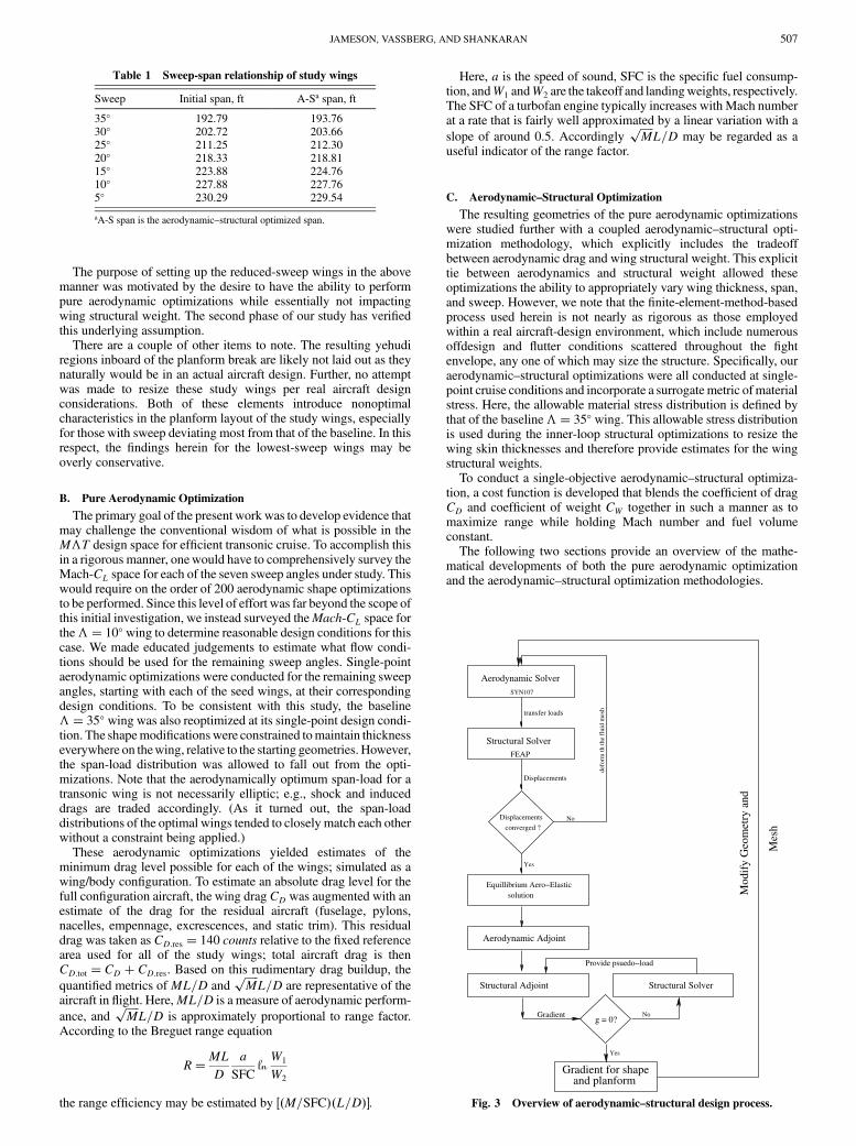
C. Aerodynamic–Structural Optimization
The resulting geometries of the pure aerodynamic optimizationswere studied further with a coupled aerodynamic–structural opti-mization methodology, which explicitly includes the tradeoffbetween aerodynamic drag and wing structural weight. This explicittie between aerodynamics and structural weight allowed theseoptimizations the ability to appropriately vary wing thickness, span,and sweep. However, we note that the finite-element-method-basedprocess used herein is not nearly as rigorous as those employedwithin a real aircraft-design environment, which include numerousoffdesign and flutter conditions scattered throughout the fightenvelope, any one of which may size the structure. Specifically, ouraerodynamic–structural optimizations were all conducted at single-point cruise conditions and incorporate a surrogate metric ofmaterialstress. Here, the allowable material stress distribution is defined bythat of the baseline�� 35� wing. This allowable stress distributionis used during the inner-loop structural optimizations to resize thewing skin thicknesses and therefore provide estimates for the wingstructural weights.
To conduct a single-objective aerodynamic–structural optimiza-tion, a cost function is developed that blends the coefficient of dragCD and coefficient of weight CW together in such a manner as tomaximize range while holding Mach number and fuel volumeconstant.
The following two sections provide an overview of the mathe-matical developments of both the pure aerodynamic optimizationand the aerodynamic–structural optimization methodologies.
Table 1 Sweep-span relationship of study wings
Sweep Initial span, ft A-Sa span, ft
35� 192.79 193.7630� 202.72 203.6625� 211.25 212.3020� 218.33 218.8115� 223.88 224.7610� 227.88 227.765� 230.29 229.54
aA-S span is the aerodynamic–structural optimized span.
Structural SolverFEAP
transfer loads
Displacements
Displacements
converged ?No
Yes
defo
rm th
the
flui
d m
esh
solutionEquillibrium Aero−Elastic
Aerodynamic SolverSYN107
Aerodynamic Adjoint
Structural Adjoint Structural Solver
Provide psuedo−load
Gradientg = 0?
No
Yes
Gradient for shape and planform
Mod
ify
Geo
met
ry a
nd
Mes
h
Fig. 3 Overview of aerodynamic–structural design process.
JAMESON, VASSBERG, AND SHANKARAN 507

Fig. 4 Cutaway of structural model for wing, showing skin, ribs, spars, and stiffeners.
SYMBOL
SOURCE DESIGN-50
DESIGN-35
DESIGN-20
DESIGN-10
DESIGN-00
ALPHA 2.500
2.368
2.320
2.311
2.274
CL 0.5267
0.5264
0.5310
0.5310
0.5314
CD 0.01573
0.01563
0.01582
0.01647
0.02075
OPTIMIZATION HISTORY OF SWEEP 10 WING/BODYREN = 65.00 , MACH = 0.800
John C. Vassberg22:52 Thu27 Dec 07
Solution 1 Upper-Surface Isobars
( Contours at 0.05 Cp )
0.2 0.4 0.6 0.8 1.0
-1.5
-1.0
-0.5
0.0
0.5
Cp
X / C 15.9% Span
0.2 0.4 0.6 0.8 1.0
-1.5
-1.0
-0.5
0.0
0.5
Cp
X / C 26.3% Span
0.2 0.4 0.6 0.8 1.0
-1.5
-1.0
-0.5
0.0
0.5
Cp
X / C 37.8% Span
0.2 0.4 0.6 0.8 1.0
-1.5
-1.0
-0.5
0.0
0.5
Cp
X / C 49.7% Span
0.2 0.4 0.6 0.8 1.0
-1.5
-1.0
-0.5
0.0
0.5
Cp
X / C 58.7% Span
0.2 0.4 0.6 0.8 1.0
-1.5
-1.0
-0.5
0.0
0.5
Cp
X / C 70.9% Span
0.2 0.4 0.6 0.8 1.0
-1.5
-1.0
-0.5
0.0
0.5
Cp
X / C 83.1% Span
0.2 0.4 0.6 0.8 1.0
-1.5
-1.0
-0.5
0.0
0.5
Cp
X / C 92.3% Span
Fig. 5 Evolution of pressures for the �� 10� wing during optimization.
508 JAMESON, VASSBERG, AND SHANKARAN

III. Aerodynamic Optimization Methodology
The shape-optimization methodology used in this work is basedon the theory of optimal control of systems governed by partialdifferential equations, where the control is by varying the shape of theboundary. We refer the reader to the following references (andreferences therein) for a detailed review of the method [1–7].
This aerodynamic shape optimization has been applied exten-sively by the authors over the past 15 years with much success on awide variety of configurations, including a Reno race plane and aMars exploration scout [8–11].
IV. Aerodynamic–StructuralOptimization Methodology
The importance of interactions between the aerodynamics and thestructures is a crucial element in the multidisciplinary design
environment that realizes a flight vehicle. Our initial attempts ataddressing this issue used the Reynolds-averaged Navier–Stokesequations to model the fluid and a simplified structural model thatdetermined a fully stressed structural layout for the given aero-dynamic loads. This approach was further refined to include adetailed finite element model for the wing, consisting of skins, spars,and ribs. Using FEAP, a finite element analysis package developedat the University of California at Berkeley, iterative aeroelasticsimulations were performed to realize the static deflected shape.
The optimal structural layout is now determined using the idea oftopology optimization [12], which has its basis in optimal control ofthe equations of static linear elasticity. Typically, an engineer isinterested in the design of a structure with minimum weight whilesatisfying the compliance conditions with respect to the externalloads, while also satisfying the constraints on maximum allowablestress. This problem has been widely studied using a discrete adjoint
Table 3 Optimum aerodynamic–structural performancea
Mach Sweep CL CD CW Cost ML=D�����Mp
L=D
0.85 35� 0.500 151.7 0.03562 0.01846 14.57 15.800.84 30� 0.510 148.7 0.03531 0.01831 14.84 16.190.83 25� 0.515 147.6 0.03537 0.01847 14.86 16.310.82 20� 0.520 148.2 0.03500 0.01839 14.80 16.340.81 15� 0.525 148.7 0.03465 0.01845 14.73 16.370.80 10� 0.530 148.6 0.03464 0.01852 14.69 16.430.79 5� 0.535 148.9 0.03455 0.01842 14.63 16.46
aCD in counts, cost� ��1CD � �2CW �maximizes Breguet range, and �1 is typically setto 1.
SYMBOL
SOURCE Aero-Struct
Pure Aero
ALPHA 2.499
2.492
CD 0.01489
0.01525
SWEEP 05 WING/BODYREN = 65.00 , MACH = 0.790 , CL = 0.535
John C. Vassberg22:35 Thu27 Dec 07
Solution 1 Upper-Surface Isobars
( Contours at 0.05 Cp )
0.2 0.4 0.6 0.8 1.0
-1.5
-1.0
-0.5
0.0
0.5
Cp
X / C 15.8% Span
0.2 0.4 0.6 0.8 1.0
-1.5
-1.0
-0.5
0.0
0.5
Cp
X / C 29.1% Span
0.2 0.4 0.6 0.8 1.0
-1.5
-1.0
-0.5
0.0
0.5
Cp
X / C 40.7% Span
0.2 0.4 0.6 0.8 1.0
-1.5
-1.0
-0.5
0.0
0.5
Cp
X / C 52.7% Span
0.2 0.4 0.6 0.8 1.0
-1.5
-1.0
-0.5
0.0
0.5
Cp
X / C 67.8% Span
0.2 0.4 0.6 0.8 1.0
-1.5
-1.0
-0.5
0.0
0.5
Cp
X / C 80.1% Span
0.2 0.4 0.6 0.8 1.0
-1.5
-1.0
-0.5
0.0
0.5
Cp
X / C 92.3% Span
Fig. 6 Optimized design at Mach 0.79 and �� 5�.
Table 2 Optimum pure aerodynamic performancea
Mach Sweep CL CD CD:tot ML=D�����Mp
L=D
0.85 35� 0.500 153.7 293.7 14.47 15.700.84 30� 0.510 151.2 291.2 14.71 16.050.83 25� 0.515 151.2 291.2 14.68 16.110.82 20� 0.520 151.7 291.7 14.62 16.140.81 15� 0.525 152.4 292.4 14.54 16.160.80 10� 0.530 152.2 292.2 14.51 16.220.79 5� 0.535 152.5 292.5 14.45 16.26
aCD in counts; CD:tot � CD � 140 counts.
JAMESON, VASSBERG, AND SHANKARAN 509

formulation in conjunction with the use of a regularizing methodthat transforms the originally ill-conditioned integer optimizationproblem to one of continuous optimization. Thus, the optimizationproblem can be written using a penalty function approach as
I��; �� �ZD
� dV � �ZD
���xs� �max�2��xs x� dV
where � is the density at each point in the structural domain (D), � isthe penalty parameter on the violation of the stress constraints, � isthe stress field in the domain, �max is the maximum allowable stress,and � is the Kronecker delta function that enables the inclusion of adomain integral in the objective function for the pointwise stressconstraints.
The constraint equations are the governing equations for linearelasticity:
@�ij�u�@xj
� fj � 0
wherefj are the combined external and internal loads on the structureandu is the displacementfield. The optimization problem can nowbeposed as follows:
min�I��; �� subject to �ij;j � fj � 0 and 0 � � � 1 (1)
Note that the constraint equation is similar in form to the viscousoperator for the Navier–Stokes equation. Proceeding in a mannersimilar to shape optimization for flow problems, we write thevariation in the cost function as
�I � @I@����u� � @I
@���
SYMBOL
SOURCE Aero-Struct
Pure Aero
ALPHA 2.497
2.498
CD 0.01487
0.01524
SWEEP 15 WING/BODYREN = 65.00 , MACH = 0.810 , CL = 0.525
John C. Vassberg22:30 Thu27 Dec 07
Solution 1 Upper-Surface Isobars
( Contours at 0.05 Cp )
0.2 0.4 0.6 0.8 1.0
-1.5
-1.0
-0.5
0.0
0.5
Cp
X / C 16.0% Span
0.2 0.4 0.6 0.8 1.0
-1.5
-1.0
-0.5
0.0
0.5
Cp
X / C 26.4% Span
0.2 0.4 0.6 0.8 1.0
-1.5
-1.0
-0.5
0.0
0.5
Cp
X / C 37.9% Span
0.2 0.4 0.6 0.8 1.0
-1.5
-1.0
-0.5
0.0
0.5
Cp
X / C 49.7% Span
0.2 0.4 0.6 0.8 1.0
-1.5
-1.0
-0.5
0.0
0.5
Cp
X / C 58.8% Span
0.2 0.4 0.6 0.8 1.0
-1.5
-1.0
-0.5
0.0
0.5
Cp
X / C 70.9% Span
0.2 0.4 0.6 0.8 1.0
-1.5
-1.0
-0.5
0.0
0.5
Cp
X / C 83.1% Span
0.2 0.4 0.6 0.8 1.0
-1.5
-1.0
-0.5
0.0
0.5
Cp
X / C 92.3% Span
Fig. 7 Optimized design at Mach 0.81 and�� 15�.
Table 4 Envelope of optimized drag polars for the 10�-sweep
wing at Mach 0.80
CL CD CD:tot L=D CW ML=D�����Mp
L=D
0.5336 151.5 291.5 18.36 0.03464 14.69 16.420.5448 154.0 294.0 18.53 0.03466 14.82 16.570.5556 157.5 297.5 18.68 0.03461 14.94 16.710.5663 161.1 301.1 18.80 0.03456 15.04 16.820.5881 168.6 308.6 19.04 0.03452 15.23 17.03
Table 5 Envelope of optimized drag polars for the baseline35�-sweep wing at Mach 0.85
CL CD CD:tot L=D CW ML=D�����Mp
L=D
0.4998 151.4 291.4 17.16 0.03562 14.59 15.820.5100 153.3 293.4 17.38 0.03561 14.77 16.020.5334 162.2 302.2 17.54 0.03559 14.91 16.170.5556 171.9 311.9 17.81 0.03554 15.14 16.420.5780 181.2 321.2 17.99 0.03550 15.29 16.590.5900 192.9 332.9 17.72 0.03540 15.06 16.34
510 JAMESON, VASSBERG, AND SHANKARAN
The variational form of the constraint equations R��; �� � 0 for anarbitrary test function � can be written asZ
D
��R��; �� � 0
where
�R� @R@��� � @R
@���
Here, the dependence of the constraint equation on the controlvariable � is through the definition of Young’s modulus:
E��� ���
�0
��
E��0�
This regularization enables � to vary smoothly between 0 and 1.Integration of the terms in the variational form of the constraint thatcontain terms corresponding to the variation in the stresses by partscan be written as Z
B
��� dBZD
@�
@xi�ij dV
The first term represents an integral over the boundary of the domain,and the test function on the boundary can be chosen to cancel the termin the variation of the cost function that depends on the variation inthe stresses. The second term can be integrated by parts again, afternoting that
�ij � E���@ui@xj
ZB
@�
@xE�ui
ZD
@
@xiE@�
@xj
where the first term is identically equal to zero, as the displacementsare either prescribed as boundary conditions or as a compliancecondition. The second term along with the boundary conditions onthe test function along the boundary is the adjoint equation. It has aform similar to the constraint equation (as it is well known thatequations of linear elasticity are self-adjoint) and can be solved usingthe finite element procedure used to obtain the displacement field.Then the cost variation reduces to
ZD
�1 �T @
@xi
@E
@�
@ui@xj
��� dV
where the bracketed expression can now be recognized as thegradient. Hence, we can use a similar adjoint approach to determinethe sensitivities of a given performance measure with respect to theshape variables and the structural layout to provide a unifiedapproach to concurrently optimize the aerodynamic and structuralcontrol variables.
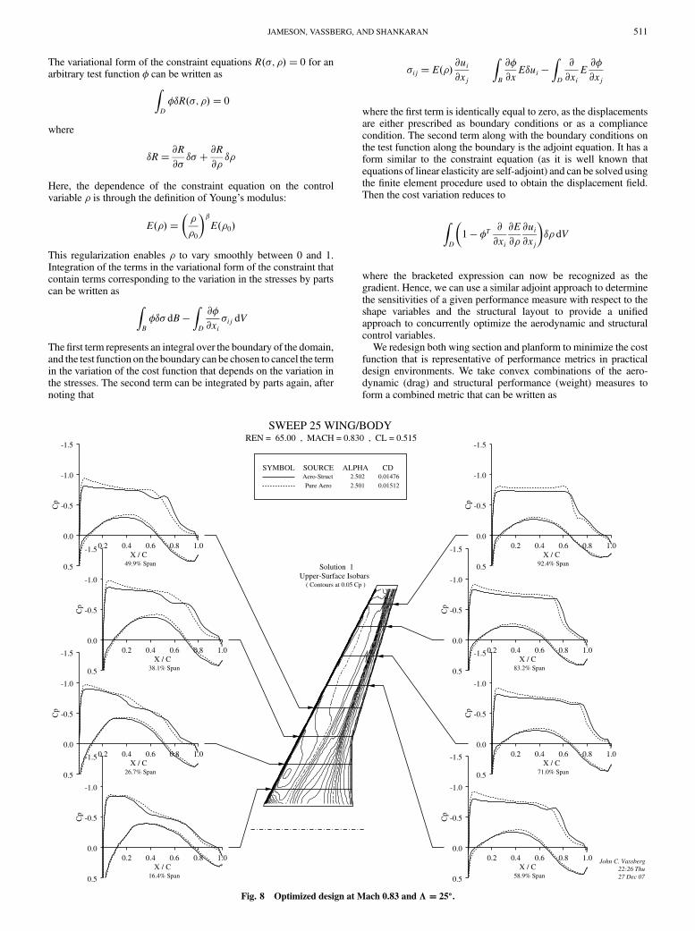
We redesign both wing section and planform to minimize the costfunction that is representative of performance metrics in practicaldesign environments. We take convex combinations of the aero-dynamic (drag) and structural performance (weight) measures toform a combined metric that can be written as
SYMBOL
SOURCE Aero-Struct
Pure Aero
ALPHA 2.502
2.501
CD 0.01476
0.01512
SWEEP 25 WING/BODYREN = 65.00 , MACH = 0.830 , CL = 0.515
John C. Vassberg22:26 Thu27 Dec 07
Solution 1 Upper-Surface Isobars
( Contours at 0.05 Cp )
0.2 0.4 0.6 0.8 1.0
-1.5
-1.0
-0.5
0.0
0.5
Cp
X / C 16.4% Span
0.2 0.4 0.6 0.8 1.0
-1.5
-1.0
-0.5
0.0
0.5
Cp
X / C 26.7% Span
0.2 0.4 0.6 0.8 1.0
-1.5
-1.0
-0.5
0.0
0.5
Cp
X / C 38.1% Span
0.2 0.4 0.6 0.8 1.0
-1.5
-1.0
-0.5
0.0
0.5
Cp
X / C 49.9% Span
0.2 0.4 0.6 0.8 1.0
-1.5
-1.0
-0.5
0.0
0.5
Cp
X / C 58.9% Span
0.2 0.4 0.6 0.8 1.0
-1.5
-1.0
-0.5
0.0
0.5
Cp
X / C 71.0% Span
0.2 0.4 0.6 0.8 1.0
-1.5
-1.0
-0.5
0.0
0.5
Cp
X / C 83.2% Span
0.2 0.4 0.6 0.8 1.0
-1.5
-1.0
-0.5
0.0
0.5
Cp
X / C 92.4% Span
Fig. 8 Optimized design at Mach 0.83 and�� 25�.
JAMESON, VASSBERG, AND SHANKARAN 511

I � �1CD � �21
2
ZB�p pd�2 dS� �3CW (2)
This form of the metric enables the designer to evaluate thetradeoffs between improvements in aerodynamic and structuralperformance. Furthermore, by varying the � vector, Pareto fronts canbe established. The aerodynamic–structural optimization procedureis schematically depicted in Fig. 3, and the structural optimization isembedded as an inner loop in the overall design process.
Thewing section is modeled by surface mesh points, and thewingplanform is modeled by several global design variables, such aschord at various locations, span, sweepback, and wing-thicknessratio [13]. The structural model can be as detailed as desired, butpresently includes the main wing box, ribs, and spars (Fig. 4). Thecalculations allow for optimization of both the sizes and layoutof the structural elements under the wing loads and changes in theaerodynamic flow due to thewing deflection. A recent aerodynamic–structural redesign of a Boeing 747 wing using this approach, butwith a lower-fidelity structural model, reduced the wing dragcoefficient fromCD � 0:0137 to 0.0114 in 20 design cycles, with thewing lift coefficient fixed at CL � 0:45, while simultaneouslyreducing the calculated wing weight by 1211 lb [14].
V. Results
Sevenwing-body configurations were studied with varying sweepangles (35, 30, 25, 20, 15, 10, and 5�). The Mach number was
systematically reduced from 0.85 for the highest-sweep wingto 0.79 for the lowest-sweep wing, and the lift coefficient wassimultaneously increased to maintain MCL roughly constant.Initial aerodynamic shape optimizations were performed on theseconfigurations, subject to the constraint that thickness could not bereduced anywhere on the wing. The results of this study aresummarized in Table 2. These optimizations show that theML=D ofthe different configurations are all within 1.8% of the maximumvalue, suggesting a relatively flat design space for aerodynamic
performance. Moreover, taking�����Mp
L=D as a better approximationto range factor, this trend yields up to a 4% improvement, favoringthe lower-swept wings. At the very least, these results show promisethat reduced-wing-sweep designs are possible for efficient transoniccruise.
To illustrate the effectiveness of the aerodynamic shape optimi-zations performed herein, Fig. 5 provides the evolution of thepressure distributions for the �� 10�-sweep wing. Pressuredistributions of the seed wing are depicted by the design-00 dashed-line curves. Also included are intermediate states for design cycles10, 20, and 35 (the total number of design cycles was preset to 50).Pressure distributions of the final design are given by the solid-linecurves of design-50. The seed wing exhibits very strong shocks overmost of its span. During the evolution of this optimization, the shocksystem is monotonically reduced in strength, with the final designcomprising only very weak shock waves. Note that the drag of theseedwing is 207.3 counts and that the drag of the final design is 157.3counts; hence, the optimization reduced the wing drag by 50 counts:about 25% in this case. This represents a substantial enhancement in
SYMBOL
SOURCE Aero-Struct
Pure Aero
ALPHA 2.503
2.498
CD 0.01517
0.01537
SWEEP 35 WING/BODYREN = 65.00 , MACH = 0.850 , CL = 0.500
John C. Vassberg22:22 Thu27 Dec 07
Solution 1 Upper-Surface Isobars
( Contours at 0.05 Cp )
0.2 0.4 0.6 0.8 1.0
-1.5
-1.0
-0.5
0.0
0.5
Cp
X / C 17.2% Span
0.2 0.4 0.6 0.8 1.0
-1.5
-1.0
-0.5
0.0
0.5
Cp
X / C 30.0% Span
0.2 0.4 0.6 0.8 1.0
-1.5
-1.0
-0.5
0.0
0.5
Cp
X / C 41.4% Span
0.2 0.4 0.6 0.8 1.0
-1.5
-1.0
-0.5
0.0
0.5
Cp
X / C 56.1% Span
0.2 0.4 0.6 0.8 1.0
-1.5
-1.0
-0.5
0.0
0.5
Cp
X / C 68.1% Span
0.2 0.4 0.6 0.8 1.0
-1.5
-1.0
-0.5
0.0
0.5
Cp
X / C 80.2% Span
0.2 0.4 0.6 0.8 1.0
-1.5
-1.0
-0.5
0.0
0.5
Cp
X / C 92.4% Span
Fig. 9 Optimized design at Mach 0.85 and�� 35�.
512 JAMESON, VASSBERG, AND SHANKARAN

aerodynamic performance that would most likely never be realizedby a cut-and-try approach.
The wings obtained from the aerodynamic shape optimizationswere then used in an aerodynamic–structural optimization proce-dure; this coupledmethod also allows formodest planformvariationswithin limits set by the feasibility of morphing the mesh. Theprocedure is outlined in Fig. 3 and is a two-stage process. Followingan aeroelastic simulation and an aerodynamic adjoint calculation, thestructural elements are redesigned while holding the aerodynamicloads fixed. Once a structure with minimum weight is obtained thatsatisfies the stress constraints, the gradients for the airfoil points andthe planform variables are determined to find the design that leads toan aerodynamic and structural performance improvement. With thisnew design, the sequence of aerodynamic–structural simulations andaerodynamic and structural adjoint calculations are repeated until alocal minimum is determined.
The results of the aerodynamic–structural optimizations aresummarized in Table 3. A similar behavior is observed for the differ-ent optimized designs. Figures 6–9 show the pressure distribution ona few of the wings with varying sweep used in this study. The aero-dynamic performance is approximately the same and the structuralweight is also roughly constant, suggesting that the aerodynamic–structural design space is also relatively flat. The planform variablesof sweep and span, in particular, reveal interesting trends. Theoptimizer tended to slightly increase the sweep across the variousconfigurations, whereas the span was slightly increased for thehigher-sweep wings and slightly decreased for the lower-sweepcases. The aerodynamic–structural optimizations permit changes inthe wing thickness; in fact, the thickness of the outboard wing wasslightly reduced at the lower sweep angles, yielding a small reductionin shock drag that contributes to the trend of an increase in the range
factor�����Mp
L=D with reduced sweep. Similar to the pure aerody-namic optimizations, there is about a 4% improvement in rangefactor for the lowest-swept wing. The actual wing sections of the
Sweep 35 WingAirfoil Geometry -- Camber & Thickness Distributions
0.0 10.0 20.0 30.0 40.0 50.0 60.0 70.0 80.0 90.0 100.0-10.0
0.0
10.0
Percent Chord
Air
foil
-1.0
0.0
1.0
2.0
Cam
ber
0.0
1.0
2.0
3.0
4.0
5.0
6.0
7.0
Hal
f-Th
ickn
ess
SYMBOL
AIRFOIL Aero-StructPure Aero
ETA 66.1 66.1
R-LE 0.840 0.908
Tavg 3.06 3.16
Tmax 4.63 4.72
@ X 40.0841.55
Fig. 10 Airfoil sections at �� 66% of optimal �� 35� wing.
Sweep 10 WingAirfoil Geometry -- Camber & Thickness Distributions
0.0 10.0 20.0 30.0 40.0 50.0 60.0 70.0 80.0 90.0 100.0-10.0
0.0
10.0
Percent Chord
Air
foil
-1.0
0.0
1.0
2.0
Cam
ber
0.0
1.0
2.0
3.0
4.0
5.0
6.0
7.0
Hal
f-Th
ickn
ess
SYMBOL
AIRFOIL Aero-StructPure Aero
ETA 65.8 65.8
R-LE 0.849 0.911
Tavg 2.92 3.15
Tmax 4.35 4.67
@ X 38.6240.08
Fig. 11 Airfoil sections at �� 66% of optimal �� 10� wing.
Outboard AirfoilAirfoil Geometry -- Camber & Thickness Distributions
0.0 10.0 20.0 30.0 40.0 50.0 60.0 70.0 80.0 90.0 100.0-10.0
0.0
10.0
Percent Chord
Air
foil
-1.0
0.0
1.0
2.0
Cam
ber
0.0
1.0
2.0
3.0
4.0
5.0
6.0
7.0
Hal
f-Th
ickn
ess
SYMBOL
AIRFOIL Sweep 35Sweep 10
ETA 66.1 65.8
R-LE 0.908 0.911
Tavg 3.16 3.15
Tmax 4.72 4.67
@ X 41.5540.08
Fig. 12 Airfoil sections at �� 66% of optimal �� 35� and �� 10�
wing.
JAMESON, VASSBERG, AND SHANKARAN 513
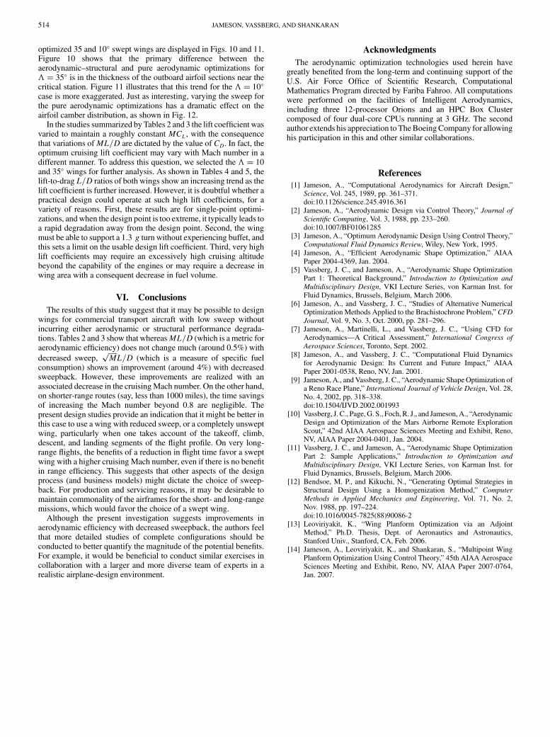
optimized 35 and 10� swept wings are displayed in Figs. 10 and 11.Figure 10 shows that the primary difference between theaerodynamic–structural and pure aerodynamic optimizations for�� 35� is in the thickness of the outboard airfoil sections near thecritical station. Figure 11 illustrates that this trend for the �� 10�
case is more exaggerated. Just as interesting, varying the sweep forthe pure aerodynamic optimizations has a dramatic effect on theairfoil camber distribution, as shown in Fig. 12.
In the studies summarized by Tables 2 and 3 the lift coefficient wasvaried to maintain a roughly constant MCL, with the consequencethat variations ofML=D are dictated by the value of CD. In fact, theoptimum cruising lift coefficient may vary with Mach number in adifferent manner. To address this question, we selected the �� 10and 35� wings for further analysis. As shown in Tables 4 and 5, thelift-to-drag L=D ratios of both wings show an increasing trend as thelift coefficient is further increased. However, it is doubtful whether apractical design could operate at such high lift coefficients, for avariety of reasons. First, these results are for single-point optimi-zations, andwhen the design point is too extreme, it typically leads toa rapid degradation away from the design point. Second, the wingmust be able to support a 1:3 g turn without experiencing buffet, andthis sets a limit on the usable design lift coefficient. Third, very highlift coefficients may require an excessively high cruising altitudebeyond the capability of the engines or may require a decrease inwing area with a consequent decrease in fuel volume.
VI. Conclusions
The results of this study suggest that it may be possible to designwings for commercial transport aircraft with low sweep withoutincurring either aerodynamic or structural performance degrada-tions. Tables 2 and 3 show that whereasML=D (which is a metric foraerodynamic efficiency) does not change much (around 0.5%) with
decreased sweep,�����Mp
L=D (which is a measure of specific fuelconsumption) shows an improvement (around 4%) with decreasedsweepback. However, these improvements are realized with anassociated decrease in the cruisingMach number. On the other hand,on shorter-range routes (say, less than 1000 miles), the time savingsof increasing the Mach number beyond 0.8 are negligible. Thepresent design studies provide an indication that it might be better inthis case to use a wing with reduced sweep, or a completely unsweptwing, particularly when one takes account of the takeoff, climb,descent, and landing segments of the flight profile. On very long-range flights, the benefits of a reduction in flight time favor a sweptwing with a higher cruising Mach number, even if there is no benefitin range efficiency. This suggests that other aspects of the designprocess (and business models) might dictate the choice of sweep-back. For production and servicing reasons, it may be desirable tomaintain commonality of the airframes for the short- and long-rangemissions, which would favor the choice of a swept wing.
Although the present investigation suggests improvements inaerodynamic efficiency with decreased sweepback, the authors feelthat more detailed studies of complete configurations should beconducted to better quantify the magnitude of the potential benefits.For example, it would be beneficial to conduct similar exercises incollaboration with a larger and more diverse team of experts in arealistic airplane-design environment.
Acknowledgments
The aerodynamic optimization technologies used herein havegreatly benefited from the long-term and continuing support of theU.S. Air Force Office of Scientific Research, ComputationalMathematics Program directed by Fariba Fahroo. All computationswere performed on the facilities of Intelligent Aerodynamics,including three 12-processor Orions and an HPC Box Clustercomposed of four dual-core CPUs running at 3 GHz. The secondauthor extends his appreciation to TheBoeingCompany for allowinghis participation in this and other similar collaborations.
References
[1] Jameson, A., “Computational Aerodynamics for Aircraft Design,”Science, Vol. 245, 1989, pp. 361–371.doi:10.1126/science.245.4916.361
[2] Jameson, A., “Aerodynamic Design via Control Theory,” Journal of
Scientific Computing, Vol. 3, 1988, pp. 233–260.doi:10.1007/BF01061285
[3] Jameson, A., “Optimum Aerodynamic Design Using Control Theory,”Computational Fluid Dynamics Review, Wiley, New York, 1995.
[4] Jameson, A., “Efficient Aerodynamic Shape Optimization,” AIAAPaper 2004-4369, Jan. 2004.
[5] Vassberg, J. C., and Jameson, A., “Aerodynamic Shape OptimizationPart 1: Theoretical Background,” Introduction to Optimization and
Multidisciplinary Design, VKI Lecture Series, von Karman Inst. forFluid Dynamics, Brussels, Belgium, March 2006.
[6] Jameson, A., and Vassberg, J. C., “Studies of Alternative NumericalOptimization Methods Applied to the Brachistochrone Problem,” CFDJournal, Vol. 9, No. 3, Oct. 2000, pp. 281–296.
[7] Jameson, A., Martinelli, L., and Vassberg, J. C., “Using CFD forAerodynamics—A Critical Assessment,” International Congress of
Aerospace Sciences, Toronto, Sept. 2002.[8] Jameson, A., and Vassberg, J. C., “Computational Fluid Dynamics
for Aerodynamic Design: Its Current and Future Impact,” AIAAPaper 2001-0538, Reno, NV, Jan. 2001.
[9] Jameson, A., and Vassberg, J. C., “Aerodynamic ShapeOptimization ofa Reno Race Plane,” International Journal of Vehicle Design, Vol. 28,No. 4, 2002, pp. 318–338.doi:10.1504/IJVD.2002.001993
[10] Vassberg, J. C., Page,G. S., Foch,R. J., and Jameson,A., “AerodynamicDesign and Optimization of the Mars Airborne Remote ExplorationScout,” 42nd AIAA Aerospace Sciences Meeting and Exhibit, Reno,NV, AIAA Paper 2004-0401, Jan. 2004.
[11] Vassberg, J. C., and Jameson, A., “Aerodynamic Shape OptimizationPart 2: Sample Applications,” Introduction to Optimization and
Multidisciplinary Design, VKI Lecture Series, von Karman Inst. forFluid Dynamics, Brussels, Belgium, March 2006.
[12] Bendsoe, M. P., and Kikuchi, N., “Generating Optimal Strategies inStructural Design Using a Homogenization Method,” Computer
Methods in Applied Mechanics and Engineering, Vol. 71, No. 2,Nov. 1988, pp. 197–224.doi:10.1016/0045-7825(88)90086-2
[13] Leoviriyakit, K., “Wing Planform Optimization via an AdjointMethod,” Ph.D. Thesis, Dept. of Aeronautics and Astronautics,Stanford Univ., Stanford, CA, Feb. 2006.
[14] Jameson, A., Leoviriyakit, K., and Shankaran, S., “Multipoint WingPlanform Optimization Using Control Theory,” 45th AIAA AerospaceSciences Meeting and Exhibit, Reno, NV, AIAA Paper 2007-0764,Jan. 2007.
514 JAMESON, VASSBERG, AND SHANKARAN