aedc arc jet test support to mars science lab tps development documents/meeting... · aedc arc jet...
TRANSCRIPT
Approved for public release; distribution is unlimited.
AEDC ARC JET TEST SUPPORT
TO MARS SCIENCE LAB TPS
DEVELOPMENT
D. Mark Smith Aerospace Testing Alliance (ATA)
Arnold Air Force Base, TN
AIAA HYTASP Technical Committee Meeting
January 9, 2012
Air Force Materiel Command
Arnold Engineering Development Center
Arnold Air Force Base, TN 37389
Approved for public release; distribution is unlimited.

AEDC ARC JET TEST SUPPORT TO MARS
SCIENCE LAB TPS DEVELOPMENT 9 JANUARY 2012
D. MARK SMITH
AEROSPACE TESTING ALLIANCE
ARNOLD AFB, TN [email protected]
Approved for public release; distribution is unlimited.

INTRODUCTION
• NASA’s Mars Science Laboratory planetary probe was launched November 25th.
The mission's rover, Curiosity, will land on Mars in August 2012 to study an
intriguing area of Mars. The rover will investigate local environmental conditions
and look for evidence of possible microbial life.
• NASA's Jet Propulsion Laboratory, a division of the California Institute of
Technology in Pasadena, manages the Mars Science Laboratory Project for the
NASA Science Mission Directorate, Washington.
• Mars Science Lab incorporates the largest-ever space vehicle heat shield ever
built for a planetary mission (including Apollo). The aeroshell is designed to
encapsulate and protect Curiosity from intense heat and friction generated during
descent through the Martian atmosphere.
• The heat shield for Mars Science Laboratory's flight will use tiles made of phenolic
impregnated carbon (PICA) ablator. The heat shield and back shell, which together
form the spacecraft’s aeroshell, have a diameter of 4.5 meters (nearly 15 feet).
• MSL heat shield testing was conducted in the AEDC H2 arc tunnel at the request
of NASA Ames Research Center, Moffett Field, CA. AEDC testing complemented
extensive MSL and Orion TPS tests in the NASA IHF/AHF and ARMSEF TP-2 arc
jets.
Approved for public release; distribution is unlimited.

OUTLINE
• Scope and objectives
• Facility and test article configuration
• Test results
• Photos and videos
All MSL Images courtesy of JPL website
http://marsprogram.jpl.nasa.gov/msl/
MSL „Curiosity‟ heat shield assembly w/
stowed rover in top shroud
Aviation Week H2 CEV TPS test article
Approved for public release; distribution is unlimited.

OVERVIEW
• Program: NASA MSL and CEV/Orion (Joint) • Sponsor: NASA Ames Research Center, Moffett Field, CA • Scope (MSL Tests): 1 validation run, 5 test runs* • Test Conductors: Robin Beck (NASA), Bill Willcockson (L-M) • Primary Data
• Facility operating conditions • Flow total enthalpy, pressure, power
• Flow calibration data • Stagnation heat flux and pressure • Wedge heat flux and pressure • 15- and 20-deg wedge angles
• TPS material response on “pilot” test samples • Digital surveillance videos to monitor ablation phenomenology • IR camera imaging • Radiometer (brightness temperature)
* Conducted as part of the larger 25-run NASA Orion TPS Advanced Development Program testing in H2
Approved for public release; distribution is unlimited.
OBJECTIVES AND APPROACH
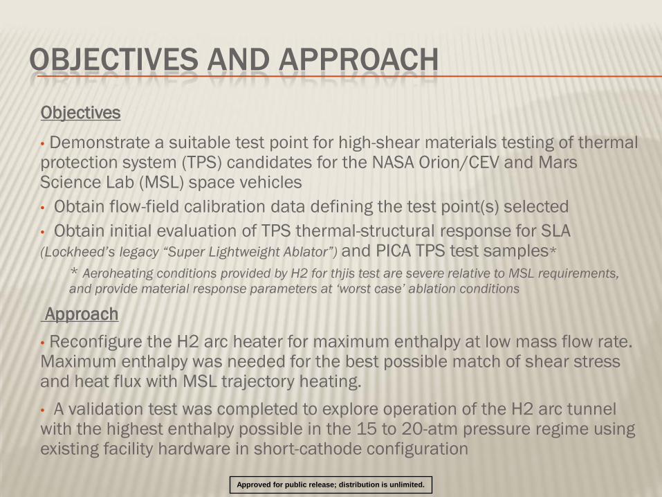
Objectives
• Demonstrate a suitable test point for high-shear materials testing of thermal protection system (TPS) candidates for the NASA Orion/CEV and Mars Science Lab (MSL) space vehicles
• Obtain flow-field calibration data defining the test point(s) selected
• Obtain initial evaluation of TPS thermal-structural response for SLA (Lockheed‟s legacy “Super Lightweight Ablator”) and PICA TPS test samples*
* Aeroheating conditions provided by H2 for thjis test are severe relative to MSL requirements, and provide material response parameters at „worst case‟ ablation conditions
Approach
• Reconfigure the H2 arc heater for maximum enthalpy at low mass flow rate. Maximum enthalpy was needed for the best possible match of shear stress and heat flux with MSL trajectory heating.
• A validation test was completed to explore operation of the H2 arc tunnel with the highest enthalpy possible in the 15 to 20-atm pressure regime using existing facility hardware in short-cathode configuration
Approved for public release; distribution is unlimited.

DAC2 Qdot vs Local Pressure, Rev.4 Margin Policy
Archive and Predicted Stagnation TP adjusted to 4" Iso-Q FC Surface
0
200
400
600
800
1000
1200
0 10 20 30 40 50 60 70 80 90 100
Surface Pressure (kPa)
Tota
l H
eat
Flu
x (
W/c
m2)
LDR ISS TP2_CEV IHF_CEV IHF171_r4iQ IHFn6_data
IHFn13_data IHFn21_data TP2_Orbiter AHFn7u AHFn12_data AHFn24_data
IHFn8c IHFn8_AA IHFn13c IHFn13_AA IHFn21c Blk2P2
env_LR_skp env_ISS_skp ARMSEF_c Orbiter_5505
CEV Risk
Concern Area #1
#2 #3 #4
CEV/MSL FORWARD HEAT SHIELD TPS RISK AREAS
CEV envelope courtesy of
Raiche, NASA/ARC (2008)
H2 nominal test points from
Smith, AEDC (2008)
#2
#4
MSL
MSL RISK AREA Target Conditions
qdot = 260 W/cm^2
t = 480 Pa
Psurf = 39 kPa
Approved for public release; distribution is unlimited.

WHY H2?
Approved for public release; distribution is unlimited.
Current
ARC IHF
Heat F
lux,
W/c
m2
Surface Pressure, kPa
Current
ARC AHF
Reactivated 7”
AHF Nozzle
0
100
200
300
400
500
600
700
800
0 10 20 30 40 50 60 70 80 90 100
JSC
TP2
(1 atm)
Flight envelopes
LDR Ballistic ISS Ballistic LDR Skip ISS Skip
#1
#2
#2 (D, NC)
M=3.4 PCH=30 atm
20-deg wedge
Qdot ~280 w/cm2
Psurf ~100 kPa
T wall ~ 900 Pa
#1 (D, C)
M=4.4 PCH=33 atm
20o wedge
Qdot ~ 60 w/cm2
Psurf ~ 18 kPa
T wall ~ 250 Pa
#3 (ND, NC)
M=3.4 PCH=20 atm
15o wedge
Qdot ~ 240 w/cm2
Psurf ~ 60 kPa
T wall ~ 590 Pa
#4 (ND, NC)
M=3.4 PCH=34 atm
10-deg wedge
Qdot ~220 w/cm2
Psurf ~ 76 kPa
T wall ~ 710 Pa
#4
Possible AEDC H2 Wedge Flow
Test Points for CEV High-Shear Key: D –Demonstrated run condition
ND—Run condition not demonstrated
C—Flow calibration data taken
NC—Calibration data not available
#A (D, C)
M=3.4 PCH=15 atm
15o wedge
Qdot ~ 210 w/cm2
Psurf ~ 45 kPa
T wall ~ 560 Pa
#3
ARC/JSC envelopes fr. Raiche, et al
MSL
MSL RISK AREA Target Conditions
qdot = 260 W/cm^2
t = 480 Pa
Psurf = 39 kPa
#A

OUTLINE
• Scope and objectives
• Facility and test article configuration
• Test results
• Photos and videos MSL aeroshell backstructure
Approved for public release; distribution is unlimited.

SUMMARY OF TEST CONDITIONS
SUMMARY: HEAT-H2 ARC HEATER AND FLOW-FIELD CONDITIONS
H2-025-003 (Validation Run)
H2-025-010 to -011 (SLA TPS Ablation Runs)
RUN NO. RUN DATE PCH ARCI ARCV PWR EFF MIX/WA MDOT RUN TIME HOB HoINF* QDOToHW** Po'
H2-025 TYPE (atm) (amp) (Kvolt) (MW) (%) (%) (lb m /s) (sec) (Btu/lb m ) (Btu/lb m ) (Btu/ft2-sec) (atm)
-003 Facility Validation 4/30/07 15.9 3,100 3.72 11.5 65 0.0 2.10 204.0 3500 4,968 2,000 2.0
-010 TPS Ablation (SLA) 8/14/07 16.8 3,073 3.96 12.2 68 0.0 2.12 136.0 3800 4,601 1,900 2.1
-011 TPS Ablation(SLA) 8/16/07 14.8 3,109 3.67 11.4 66 0.0 1.88 126.0 3900 4,969 1,930 1.9
NASA MSL Facility Validation and TPS Testing
*Nominal centerline inferred enthalpy ** Stagnation heat flux on a 0.25"R hemisphere calorimeter ***Average bulk enthalpy for runs -010 to -011.
Additional PICA and SLA samples were
tested for MSL on Runs -012, -013, and -014.
Approved for public release; distribution is unlimited.

OUTLINE
• Scope and objectives
• Facility and test article configuration
• Test results
• Photos and videos MSL aeroshell w/ mock heat shield in place
Approved for public release; distribution is unlimited.

H2 WEDGE FLOW PROPERTIES
DMS 8-17-07
Run Facility PCH Wedge > Mfs Hr Vfs Me Me/Mfs Ue*
H2-025 atm deg Btu/lbm ft/sec Btu/ft2-sec w/cm
2 atm kPa M ft/sec lb/ft2 Pa
-001 H2 23.0 15 3.4 5000 11,920 320 362 0.61 61.8 2.04 0.60 7152 14.2 711
20 3.4 5000 11,920 400 452 0.72 72.8 1.90 0.56 6675 16.6 829
-002 H2 23.0 15 3.4 4200 11,200 280 316 0.61 61.8 2.04 0.60 6720 13.9 696
20 3.4 4200 11,200 340 384 0.72 72.8 1.90 0.56 6272 15.8 788
-003 H2 16.0 15 3.4 4600 11,520 200 226 0.43 43.0 2.04 0.60 6912 9.3 467
20 3.4 4600 11,520 260 294 0.50 50.7 1.90 0.56 6451 11.3 566
-010 H2 16.8 10 3.4 4600 11,520 180 203 0.31 31.6 2.14 0.64 7373 9.0 448
-011 H2 14.8 15 3.4 4800 11,720 210 237 0.40 40.4 2.14 0.60 7032 9.6 478
NASA-MSL H2 Test Points
Qcw Psurf
H2-025 Tests
Gas Wall Shear
Note: Runs -001 and -002 were Orion facility validation runs.
AEDC wedge and stagnation sweep probes
Additional PICA and SLA samples were tested
for MSL on Runs -012, -013, and -014.
Typical Test Points for NASA MSL H2 Arc Jet Tests
Approved for public release; distribution is unlimited.

PRETEST PHOTOS--PICA
Acreage PICA—0-deg fiber 20-deg fiber—away from the flow 40-deg fiber—away from the flow
RTV-fillled 0.100 gap. Fiber
orientation +/- 10 deg on gap sides RTV-fillled 0.100 gap. Fiber orientation
+/- 20 deg on gap sides
Approved for public release; distribution is unlimited.
Ref. Beck, et al, “Quick Summary of CEV/MSL PICA Shear Tests at AEDC, NASA QLDR, Jan., 2008.

POSTTEST PHOTOS--PICA
Acreage PICA—0-deg fiber 20-deg fiber—away from the flow 40-deg fiber—away from the flow
RTV-fillled 0.100 gap. Fiber orientation
+/- 10 deg on gap sides RTV-fillled 0.100 gap. Fiber orientation
+/- 20 deg on gap sides
RTV-fillled 0.100 gap. Fiber
orientation +/- 0 deg on gap sides
Approved for public release; distribution is unlimited.
Ref. Beck, et al, “Quick Summary of CEV/MSL PICA Shear Tests at AEDC, NASA QLDR, Jan., 2008.

RECESSION COMPARISON—PICA VARIANTS
Acreage PICA (Variant AA-46-206N) ___
Surface Densified PICA (Shear 1-Appr-B)
Distance From Front of the Sample (mm)
Su
rfa
ce
Re
ce
ssio
n (
mm
)
20-deg wedge (PICA acreage)
20-deg
wedge
(CEV ADP
Entry I)
20-deg
wedge
(CEV ADP
Entry II)
Average PICA Recession Comparison—Entry I and II
Approved for public release; distribution is unlimited.
Ref. Beck, et al, “Quick Summary of CEV/MSL PICA Shear Tests at
AEDC, NASA QLDR, Jan., 2008.

PRETEST PHOTOS--SLA
Sample # 4
Flow
Flow
Flow Sample # 5
Sample # 2
Approved for public release; distribution is unlimited.

ARC-ON PHOTOS--SLA
Sample # 4
Flow
Flow
Flow Sample # 5
Sample # 2
Approved for public release; distribution is unlimited.

H2 TEST VIDEO (TYPICAL)
H2 Test Video--Typical CEV/MSL Run
Test article indexes in @ t=32 sec
Approved for public release; distribution is unlimited.
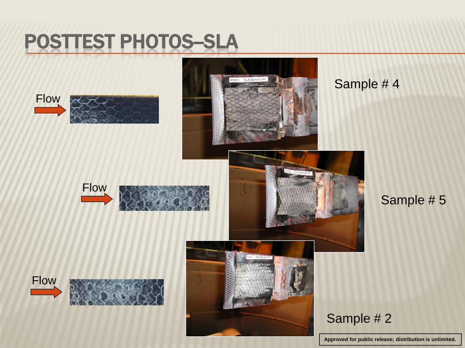
POSTTEST PHOTOS--SLA
Sample # 4
Flow
Flow
Flow Sample # 5
Sample # 2
Approved for public release; distribution is unlimited.
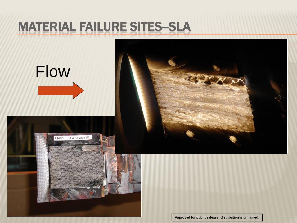
MATERIAL FAILURE SITES--SLA
Sample # 4
Flow
Flow
Sample # 5
Approved for public release; distribution is unlimited.

CONCLUSIONS
• Relative performance of PICA variants and SLA TPS were evaluated in
H2 high-shear ablation tests and in comparative testing at NASA ARC
and JSC
• FMI’s PICA material (also of interest at the time for CEV applications)
exhibited good high-shear thermal performance for acreage and gap
seals at the test conditions of interest
• The legacy SLA TPS material exhibited inadequate thermostructural
integrity when tested at the maximum-shear conditions anticipated for
MSL planetary entry on the forward heat shield
• Posttest ablative honeycomb site vacancies were observed in both the H2 arc tunnel
at max shear and at NASA AHF/IHF arc jets in testing under moderate-shear
conditions with add-air (mixing air)
• Existing material response models were inadequate to predict material response
with appropriate survivability margins at elevated shear levels
NASA selected PICA as MSL forward heat shield TPS material
SLA-561 V was selected as backshell TPS material for MSL
Approved for public release; distribution is unlimited.
OUTLINE
• Scope and objectives
• Facility and test article configuration
• Test results
• Photos and videos
Approved for public release; distribution is unlimited.

MSL PHOTOS Ref. Link: MSL “Curiosity” images from JPL website:
http://mars.jpl.nasa.gov/msl/multimedia/images/
DHS Spirit = ~8.5 ft.
DHS Apollo = ~13.0 ft.
DHS MSL = ~15.0 ft.
DHS MPCV = ~16.5 ft.
Curiosity rover in “stowed” configuration MSL Mars entry aeroshell
MSL payload arrving at launch pad
Finishing touches on the stowed rover
Approved for public release; distribution is unlimited.
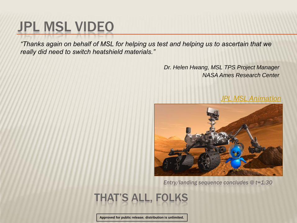
JPL MSL VIDEO
JPL MSL Animation
THAT’S ALL, FOLKS
Entry/landing sequence concludes @ t=1:30
“Thanks again on behalf of MSL for helping us test and helping us to ascertain that we
really did need to switch heatshield materials.”
Dr. Helen Hwang, MSL TPS Project Manager
NASA Ames Research Center
Approved for public release; distribution is unlimited.