adzlyanuar © 2004 isometric projection drawing chapter 6
TRANSCRIPT

adzl
yanu
ar ©
200
4
Isometric Projection Drawing
CHAPTER 6

adzl
yanu
ar ©
200
4-20
05
MEMB113 | MANUAL DRAWING | CHAPTER 6MEMB113 | MANUAL DRAWING | CHAPTER 6
ContentContent• Overview
– Pictorial projection– Parallel projection– Axonometric projection
• Isometric projection– Axes and selection– Isometric lines and planes– Isometric scale– Isometric projection & Isometric drawing
• Producing Isometric sketches & drawing– Isometric lines & non-isometric lines– Circles and arcs– Irregular curves
• Oblique projection drawing

adzl
yanu
ar ©
200
4-20
05
MEMB113 | MANUAL DRAWING | CHAPTER 6MEMB113 | MANUAL DRAWING | CHAPTER 6
6.16.1 Pictorial projectionPictorial projection• Pictorial projection:
– Not intended to give exact or true view.
– Not intended to transmit dimensions, although sometimes dimension is useful.
– Useful when the information and instructions to be given to non-technical and untrained people.
– Hidden lines are not shown in isometric drawing.

adzl
yanu
ar ©
200
4-20
05
MEMB113 | MANUAL DRAWING | CHAPTER 6MEMB113 | MANUAL DRAWING | CHAPTER 6
6.16.1 Parallel projection Parallel projection techniquetechnique
adzl
yanu
ar ©
200
4-20
05
MEMB113 | MANUAL DRAWING | CHAPTER 6MEMB113 | MANUAL DRAWING | CHAPTER 6
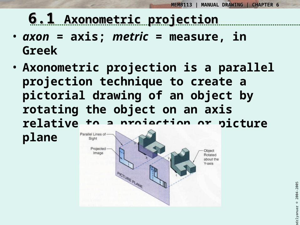
6.16.1 Axonometric projectionAxonometric projection• axon = axis; metric = measure, in
Greek• Axonometric projection is a parallel
projection technique to create a pictorial drawing of an object by rotating the object on an axis relative to a projection or picture plane

adzl
yanu
ar ©
200
4-20
05
MEMB113 | MANUAL DRAWING | CHAPTER 6MEMB113 | MANUAL DRAWING | CHAPTER 6
6.16.1 Axonometric projectionAxonometric projection• Axonometric projection
– Trimetric– Dimetric– Isometric

adzl
yanu
ar ©
200
4-20
05
MEMB113 | MANUAL DRAWING | CHAPTER 6MEMB113 | MANUAL DRAWING | CHAPTER 6
6.16.1 Axonometric projectionAxonometric projection

adzl
yanu
ar ©
200
4-20
05
MEMB113 | MANUAL DRAWING | CHAPTER 6MEMB113 | MANUAL DRAWING | CHAPTER 6
6.26.2 Isometric projectionIsometric projection• Isometric projection is a true representation
of the isometric view of an object• Isometric view is created by rotating the
object 45 degree about vertical axis, and tilting it forward 35 deg 16’

adzl
yanu
ar ©
200
4-20
05
MEMB113 | MANUAL DRAWING | CHAPTER 6MEMB113 | MANUAL DRAWING | CHAPTER 6
6.26.2 Isometric projection: axesIsometric projection: axes• The 3 axis meet at A,B form equal
angles of 120 deg and they are called Isometric Axes
• OA is vertical, OB is inclined at 30deg to the right, OC is inclined at 30deg to the left
• Any lines parallel to these – Isometric Line
• Any planes parallel – Isometric Planes

adzl
yanu
ar ©
200
4-20
05
MEMB113 | MANUAL DRAWING | CHAPTER 6MEMB113 | MANUAL DRAWING | CHAPTER 6
6.26.2 Selection of Isometric AxesSelection of Isometric Axes• Main purpose of isometric view is to provide a
pictorial view which reveals as much detail as possible• Selection of principal edges is important• Figure shows different isometric views of the same
block

adzl
yanu
ar ©
200
4-20
05
MEMB113 | MANUAL DRAWING | CHAPTER 6MEMB113 | MANUAL DRAWING | CHAPTER 6
6.26.2 Isometric projection: scaleIsometric projection: scale• The tilt causes the edges & planes to
become foreshortened• The projected length is approximately
80% of the true length

adzl
yanu
ar ©
200
4-20
05
MEMB113 | MANUAL DRAWING | CHAPTER 6MEMB113 | MANUAL DRAWING | CHAPTER 6
6.26.2 Isometric projection & Isometric projection & drawingdrawing
• Isometric projection & Isometric drawing– Isometric projection: drawn at scale of
0.816– Isometric drawing: drawn at full scale

adzl
yanu
ar ©
200
4-20
05
MEMB113 | MANUAL DRAWING | CHAPTER 6MEMB113 | MANUAL DRAWING | CHAPTER 6
6.26.2 Iso-lines & Iso-planes: Iso-lines & Iso-planes: examplesexamples

adzl
yanu
ar ©
200
4-20
05
MEMB113 | MANUAL DRAWING | CHAPTER 6MEMB113 | MANUAL DRAWING | CHAPTER 6
6.36.3 Non-isometric linesNon-isometric lines
• Non-isometric lines are the lines that are not parallel to any of the iso-lines.
• They are drawn by transferring the distance of X or Y from multi-view to iso-view, not the actual length itself.
L
L
L is orthogonal not equal to L in isometric

adzl
yanu
ar ©
200
4-20
05
MEMB113 | MANUAL DRAWING | CHAPTER 6MEMB113 | MANUAL DRAWING | CHAPTER 6
6.36.3 Isometric angles & non-iso Isometric angles & non-iso lineslines
• Example of producing non-isometric lines.
• The position of point Z is obtained in the isometric view, by transferring the distance of X and Y.

adzl
yanu
ar ©
200
4-20
05
MEMB113 | MANUAL DRAWING | CHAPTER 6MEMB113 | MANUAL DRAWING | CHAPTER 6
6.36.3 Iso-circles and arcsIso-circles and arcs• Isometric circles or iso-circle cannot be
simply drawn using compass.• Any iso-circle may lie on either top
plane, left (front) plane or right (profile) plane.
• Iso-circle looks slightly oval and skewed.

adzl
yanu
ar ©
200
4-20
05
MEMB113 | MANUAL DRAWING | CHAPTER 6MEMB113 | MANUAL DRAWING | CHAPTER 6
6.36.3 Iso-circles and arcs: drawIso-circles and arcs: draw• Drawing isometric circles and arcs
using four-centre method

adzl
yanu
ar ©
200
4-20
05
MEMB113 | MANUAL DRAWING | CHAPTER 6MEMB113 | MANUAL DRAWING | CHAPTER 6
6.36.3 Producing isometric circleProducing isometric circle– Draw centre lines AOB and COD, O is
centre of circle, AO=OB=CO=OD = radius of circle.
– Draw FCG and EDH parallel to AOB, draw FAE and GBH parallel to COD.
– Draw diagonal FOH, mark points J and K where FJ = HK = radius of circle.
– With centre G and rad. R1 = GA, draw an arc between GJ produced at L and GK produced at M. Similarly with centre E.
– With centres J and K and radius R2 = JL and KM, complete the figure.
adzl
yanu
ar ©
200
4-20
05
MEMB113 | MANUAL DRAWING | CHAPTER 6MEMB113 | MANUAL DRAWING | CHAPTER 6
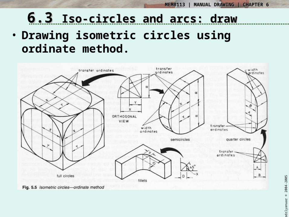
6.36.3 Iso-circles and arcs: drawIso-circles and arcs: draw• Drawing isometric circles using
ordinate method.

adzl
yanu
ar ©
200
4-20
05
MEMB113 | MANUAL DRAWING | CHAPTER 6MEMB113 | MANUAL DRAWING | CHAPTER 6
6.36.3 Drawing iso-circlesDrawing iso-circles
• To draw an iso-circle, on left plane, Diameter 20mm
(a) Draw centre lines, vertical & 30deg to left.
(b) Draw (construction line) 20mm “square box”. The centre lines should divide each side by half.
(c) Draw straight lines; 1-2 & 1-3 and 2-5 & 2-6.(d) Point 7 is the intersection between line 1-2 & 2-5, and similarly point 8, 1-3 &
2-6 on the other side.(e) Set your compass to the distance 7-2, draw an arc with centre at point 7,
from point 2 to point 5. Do the same on the other side.(f) Set your compass to the distance 1-2, draw an arc with centre (1), from (2) to
(3).
(a)
12
3
4
5
6
7
8
2
5
4
5
6
(b) (c)
(d) (e) (f)

adzl
yanu
ar ©
200
4-20
05
MEMB113 | MANUAL DRAWING | CHAPTER 6MEMB113 | MANUAL DRAWING | CHAPTER 6
6.36.3 Irregular curves in isometricIrregular curves in isometric• Irregular curves in
isometric are produced by transferring the coordinates from orthogonal view.
• A fixed distance is set, A, and the distance in B direction are obtained.
• These values are then transferred to the isometric view.

adzl
yanu
ar ©
200
4-20
05
MEMB113 | MANUAL DRAWING | CHAPTER 6MEMB113 | MANUAL DRAWING | CHAPTER 6
6.36.3 Producing Isometric Producing Isometric SketchesSketches
• Isometric drawing starts with isometric sketches.
• Begin with defining isometric axis.• Begin sketch by extending axes –
vertical lines, 30deg left & right.

adzl
yanu
ar ©
200
4-20
05
MEMB113 | MANUAL DRAWING | CHAPTER 6MEMB113 | MANUAL DRAWING | CHAPTER 6
6.36.3 Producing Isometric Producing Isometric SketchesSketches
• Sketch an isometric ‘box’.• Sketch the view on each faces,
starting with isometric lines.• Add in non-iso lines and other details• Darken all visible lines.

adzl
yanu
ar ©
200
4-20
05
MEMB113 | MANUAL DRAWING | CHAPTER 6MEMB113 | MANUAL DRAWING | CHAPTER 6
6.36.3 Iso-circles and arcs: sketchIso-circles and arcs: sketch• Sketching iso-circle is simpler than drawing.• Create isometric square, each side=diameter.• Find the centre point and midpoints of each side.• Use the construction lines and point to sketch each quarter
of the circle.

adzl
yanu
ar ©
200
4-20
05
MEMB113 | MANUAL DRAWING | CHAPTER 6MEMB113 | MANUAL DRAWING | CHAPTER 6
6.36.3 Sketching isometric Sketching isometric cylindercylinder
• Start by drawing the bounding box.• The front end of the cylinder is sketched using the previous
technique.• The far end of the cylinder is a partial iso-circle. Sketch until
meeting the tangent with the two straight lines.

adzl
yanu
ar ©
200
4-20
05
MEMB113 | MANUAL DRAWING | CHAPTER 6MEMB113 | MANUAL DRAWING | CHAPTER 6
6.46.4 Producing Isometric Producing Isometric drawingdrawing– Read the orthogonal drawing carefully,– observe the scale, – choose the best point where isometric
axes meet to reveal as much detail as possible
– draw an 'isometric box' enclosing the object
– draw in light construction lines– draw arc & curves in thick, remove
excess..– line in 30 right lines– line in 30 left lines– line in vertical lines to complete the view
adzl
yanu
ar ©
200
4-20
05
MEMB113 | MANUAL DRAWING | CHAPTER 6MEMB113 | MANUAL DRAWING | CHAPTER 6
6.46.4 Producing Isometric Producing Isometric drawingdrawing
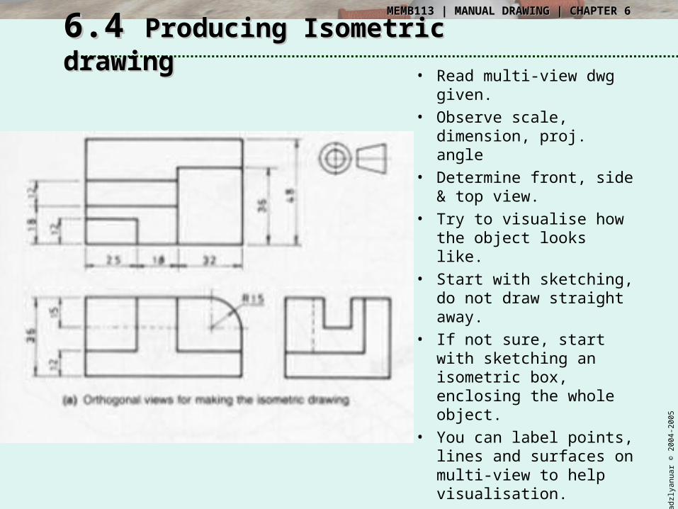
• Read multi-view dwg given.
• Observe scale, dimension, proj. angle
• Determine front, side & top view.
• Try to visualise how the object looks like.
• Start with sketching, do not draw straight away.
• If not sure, start with sketching an isometric box, enclosing the whole object.
• You can label points, lines and surfaces on multi-view to help visualisation.

adzl
yanu
ar ©
200
4-20
05
MEMB113 | MANUAL DRAWING | CHAPTER 6MEMB113 | MANUAL DRAWING | CHAPTER 6
6.46.4 Producing Isometric Producing Isometric drawingdrawing
• You can start drawing, once you’re able to visualise how the object looks like, or finish sketching.
• Start with drawing construction line – draw the iso-box, and fill up with other lines.
• Line in (darken) arcs & circles.
• Line in iso-lines.• Line in all other
lines.

adzl
yanu
ar ©
200
4-20
05
MEMB113 | MANUAL DRAWING | CHAPTER 6MEMB113 | MANUAL DRAWING | CHAPTER 6
6.46.4 Producing Isometric Producing Isometric drawingdrawing

adzl
yanu
ar ©
200
4-20
05
MEMB113 | MANUAL DRAWING | CHAPTER 6MEMB113 | MANUAL DRAWING | CHAPTER 6
6.56.5 Isometric dimensionsIsometric dimensions
• Although isometric drawing is not intended to transmit dimension, sometimes dimensions are placed to indicate the size.
• Two types:

adzl
yanu
ar ©
200
4-20
05
MEMB113 | MANUAL DRAWING | CHAPTER 6MEMB113 | MANUAL DRAWING | CHAPTER 6
6.56.5 Isometric featuresIsometric features• Common feature shown in isometric drawing.
Screw thread (external)
Fillet and rounds
Isometric section view

adzl
yanu
ar ©
200
4-20
05
MEMB113 | MANUAL DRAWING | CHAPTER 6MEMB113 | MANUAL DRAWING | CHAPTER 6
6.56.5 Isometric assembly: 3D Isometric assembly: 3D renderrender

adzl
yanu
ar ©
200
4-20
05
MEMB113 | MANUAL DRAWING | CHAPTER 6MEMB113 | MANUAL DRAWING | CHAPTER 6
6.56.5 Isometric exploded Isometric exploded assemblyassembly

adzl
yanu
ar ©
200
4-20
05
MEMB113 | MANUAL DRAWING | CHAPTER 6MEMB113 | MANUAL DRAWING | CHAPTER 6
6.66.6 Oblique projection drawingOblique projection drawing• Oblique
projection – parallel projection where the projectors are parallel to each other but not perpendicular to the projection plane

adzl
yanu
ar ©
200
4-20
05
MEMB113 | MANUAL DRAWING | CHAPTER 6MEMB113 | MANUAL DRAWING | CHAPTER 6
6.66.6 Oblique projection drawingOblique projection drawing• The actual angle that the projectors
make with the plane is not fixed, but preferably between 30deg – 60deg
• Most common 45 degree

adzl
yanu
ar ©
200
4-20
05
MEMB113 | MANUAL DRAWING | CHAPTER 6MEMB113 | MANUAL DRAWING | CHAPTER 6
6.66.6 Oblique projection drawingOblique projection drawing• 3 types:
– Cavalier projection: true length along axis– Cabinet projection: half true length– General: any from half to full true length

adzl
yanu
ar ©
200
4-20
05
MEMB113 | MANUAL DRAWING | CHAPTER 6MEMB113 | MANUAL DRAWING | CHAPTER 6
6.66.6 Oblique projection drawingOblique projection drawing• Place complex
surfaces (arcs, holes, irregular curve, etc.) parallel to front plane
• The longest dimension should be parallel to frontal plane

adzl
yanu
ar ©
200
4-20
05
MEMB113 | MANUAL DRAWING | CHAPTER 6MEMB113 | MANUAL DRAWING | CHAPTER 6
6.76.7 Producing oblique sketchProducing oblique sketch
• First, sketch the front face.• Project 45 deg line to the back.• For holes, determine the visibility.• Line in all object lines.

adzl
yanu
ar ©
200
4
End of Chapter 6THANK YOU