advisory circular - federal aviation administration · in effect, new designs which ... when...
TRANSCRIPT

p /4 0 14 ) :: ; * , + /
i i./ AC 20-30B
DATE 7120181
ADVISORY CIRCULAR DEPARTMENT OF TRANSPORTATION
Federal Aviation Administration
Washington, D.C.
FARCXIIDANCEMATERIAL
Subject:AIRCRAFT FOSITICN LICi-lT AND AI'IIIC(X,LISIoN LIGHT mSTALLATIC)WS
1. PURPOSE. Ihis circular sets forth acceptable means, but mt the only means, of wqliance with the Federal Aviation Regulations (FAR) applicable to installed position lights and anticollision lights.
2. CANCELLATION. AC 20-30A dated April 18, 1968, is canceled.
3. RFJATEDFARSFCTIONS.
a. Sections .1385 through .1401 of FAR Parts 23, 25, 27, and 29.
b. Sections .33 and .73 of FAR Part 91.
4. RELATED READING MATERIAL,.
a. Advisory Circular AC 20-74, Aircraft Position Lights and Anticollision Light Measurements.
b. Advisory Circular AC 43.13-2A, Acceptable Methods, lkchniques, and Practices, Aircraft Alterations.
c. Technical Standard Order (TSO) C30b, Aircraft Position Lights.
5. RACKGRODND. Aimrthiness regulations and Technical Standard Orders prescribe minimum intensities, light distribution, overlap limits, allowable obstructions to light visibility, and color for position lights and antiallision lights.
6. LABORA!I0RYMEASUREMENS. Measurements of intensity, light distribution, and 'Iight color are normally made under laboratory conditions before installation. Advisory Circular 20-74 contains information concerning measurements of intensity, distribution, and color.
Initiated by: AWS-100
AC 20-30B 7120181
7. POSITION LIGHT SYSTEM INSTALLATION.
a. Location. In determining whether forward position lights have been "spaced laterally as far apart as practicable," and whether the rear position light has been "mounted as far aft as practicable," as required by the FAR's, each installation may be evaluated for special considerations. Examples of special consideration are:
(1) Would the maker of malfunctions be significantly increased due to increased vibration or other environmental conditions if the lights were spaced farther apart, or sounted farther aft?
(2) Would accessibility for maintenance be sigr'ificantly reduced if the lights were spaced farther apart or farther aft?
b. Rear Position Light Obstructions. A small light obstruction is per- -8 . mitted within dihedral angle A (aft) described in 3 .1387(d) of Parts 23, 25, 27, and 29. That obstruction is limited in size to 0.04 steradian and in position to the 30' cone described in 3 .1387(e) of Parts 23, 25, 27, and 29 and shown in Figure 1. Measurements to show compliance with the regulations can be made on actual aircraft or on appropriate scale drawings. The following procedure is one means of shming compliance with the regulations:
(1) On the side view drawing, draw a line through the light center perpendicular to the aircraft longitudinal axis. Draw a second line upward through the light center to the nest aft point an the vertical stabilizer. The angle z between the two lines is limited by the airworthiness rules to 3o". Figure lshows an example of angleZ.
(2) On the rear view drawing, draw angle W which is formed by two lines drawn upward from the light center to the maxknun right and left obstructions within angle z. When a protrusion causes a very small zone of obstruction it may be discounted unless total obstructions are near the regulatory limit. When a rear view drawing is mt available, a combination of other drawings or measurants on the actual aircraft can be used to detemine angle W.
(3) Multiply angle z degrees by angle W degrees to obtain the auMunt of obstruction in square degrees. The method is conservative, as obstructions as wide as angle W may mt exist throughout angle Z. Convert the measurement to steradians by dividing the square degree value by 3284. The number 3284 is a conversion factor to obtain steradians from square degrees.
8. AN~I~~L;LI~I~N LIGHTS
a. Airworthiness Requirements. Appendix 1, Tables 3 through 6., summarize the airworthiness requirements for anticollision lights and lists them according to the applicable amendments to the CAR's/FAR's. The airworthiness requirements for a specific aircraft can usually be determined by entering the applicable table with the latest amendment shown for the certification basis in the aircraft's type certificate data sheet.
2 Par 7

7120181
FIGURE 1. REAR POSITION LIGHT OBSTRUCTIONS
I ANGLE I
LIGHT
AC 20-30B
REAR VIEW
AC2&3OB 7120181
b. Operational Requirements. Some airworthiness requirements have been made retroactive by %nendment 91-90, which amended S 91.33(c)(3) of the RAR. The term "initially installed" used in this section refers ti new installations based an newly-approved design data or any installation &ich includes a major change as defined in FAR 21.93(a) to the previously approved design data. In effect, new designs which have had m previous FAA approval are considered initially installed systems. Anticollision light installations approved by Major Repair and Alteration (Airframe, PaJerplant, Propeller, or Appliance), FAA Form 337, supplemental type certificate or amended type certificate prior to August 11, 1971, may be duplicated cn like make and model aircraft without being considered initially installed.
c. Obstruction Measurements. When anticollision light obstructions are allowed within the required field of coverage, measurements on shadows, scale drawings or actual aircraft can be used to substantiate that solid angles of obstruction do not exceed regulatory limits. When masking is used to prevent the impairment of crew vision, the mask becomes an additional light obstruction. The amount of obstruction caused by the mask depends not only on the physical size of the mask, but also on the type and size of the light source. With rotating beacons, the mask obstruction may be slightly larger than indicated by the physical size of the mask. This condition results frcm the lack of a sharp cutoff of light at the mask edges. As the reflector rotates, there is a gradual reduction of light near the mask edges due ti the relatively large size of the light source. Accurate measurement of mask obstruction can best be acccmplished during the laboratory measurement of intensity and field of coverage. Otherwise, total obstructions measured very near the regulatory limit may actually exceed that limit.
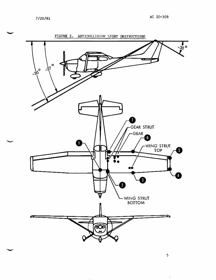
d. The following procedures refer ti the example shown in Figure 2. Scale drawings and measurements from the light unit are used in substantiating compliance with the anticollision light requirements. The procedure with variations can be applied to other aircraft. Variations include other shapes and vertical coverage requirements. The procedure converts scale drawing obstructions to a plot of horizontal versus vertical degrees where area units become square degrees. E3y counting the squares within obstructions and converting the sum to steradians, compliance can be shown. Scale drawings should be large enough to assure reasonable accuracy in the measurements. For the example, the vertical average requirement is +30°. -
(1) Fuselage and Wings.
(i) Point selection. c)n the top view, establish enough points to adequately follow the shape of obstructions. In the example of Figure 2, seven points are established and numbered to represent the left half of the fuselage and the left wing. Because of synmetry, measurements are limited to one side, and the measured obstructed area is doubled to account for the other side of the aircraft. Additional obstructions, not represented by the seven n&red points, include mask, wing struts, landing gear, and rudder. These additional obstructions are considered separately.
4 Par 8
7120181 AC 20-30B
WING STRUT BOTTOM
5

AC 20-30B 7120181
I I I I I I I I
7120181 AC 20-30B
(ii) Horizontal angles. On the top view of Figure 2, measure the horizontal angles between the aircraft centerline and lines connecting the anticollision light center to the numbered points.
(iii) 'Vertical angles. On the side view of Figure 2, measure the vertical angles from the horizontal plane passing through the anticollision light center to lines connecting the light center to the numbered points.
(iv) Tabulation. Tabulate the measured horizontal and vertical angles as shawn in Table 1.
NWIE: In lieu of direct angle measurements, distance measurements may be used to calculate the angles using trigonometry relationships.
(2) Wing strut angles. On the top view of Figure 2, establish right and left points for the strut top and fore and aft points for the strut bottom. Horizontal angles for the strut bottom points are approximately equal. Measure the horizontal and vertical angles to the four points and tabulate as shown in Table 1.
(3) Main gear fairing. On the top of Figure 2, establish four points for the main gear fairing obstruction. The rear obstruction limit is the -30" vertical coverage requirement, an d the forward obstruction extends to vertical angles of -27". The effect of wheel fairing rounding is slight and is neglected. Measure the horizontal angles to the four points, and tabulate as
* shown in Table 1.
(4) Main gear strut. Gn the top view of Figure 2, establish four points for the main gear strut. Measure the horizontal and vertical angles to the four points, and tabulate as shown in Table 1.
(5) Rudder obstructions. On the side view of Figure 2, rudder cbtstruc- tions occur aft of the anticollision light while all other obstructions are forward. Therefore, it is practical to measure rudder obstructions independently. On the side view of Figure 2, the rudder obstructs for 30 vertical degrees. (% the top view, the obstruction is 3 horizontal degrees on the left side. The left side rudder obstruction is 90 square degrees; i.e., 30" x 3" = 90 square degrees.
(6) Calculating obstructions. The graph of Figure 3 shows plotting of the collected data of Table 1 as vertical degrees versus horizontal degrees. Each square is equal to one square degree so that obstructions can be measured by oounting squares. Obstruction areas can be munted in zones bounded by vertical lines through the numbered points. Table 2 shows the counts including the rudder obstruction which was measured independent of the graph. Square degrees are converted to steradians by dividing by 3284.
Director of Airworthiness
Par 8

7/20/81
OBSTRUCTION
Wing/Fuselage
Strut
Gear
Gear Strut
Mask (Positioned to eliminate reflections from prop)
TABLE 1. OBSTRUCTION POINT ANGLES
HORIZONTAL POINT ANGLE
1 O0 2 7" 3 25' 4 47" 5 52' 6 32" 7 8"
Top Right Top Left Bottom Upper Bottom Lower
22O 24'
7O 7O
Front Right Front Left Rear Right Rear Left
12" 15.5O 13" 16.5'
Top Front Top Rear Bottom Front Bottom Rear
8" 8'
13O 13"
Top Centerline Top Left Bottom Centerline Bottom Left
O0 10" O0
10"
AC 20-30B Appendix 1
VERTICAL ANGLE
-7.5O -7.0° -5.5O -7.5O
-12" -13" -12"
-8.5" -9.0°
-22" -23.5"
-27" -27" -30" -30"
-24" -25" -28.5" -29.5"
-10" -10" -30" -30°

AC 20-30B Appendix 1
ZONE
7/20/81
TABLE 2. OE3STRtXTIONCQUNT
SQUARE DEGREES
FG.nt1to mint 2 159 Point 2to Eoint 3 198 Point 3toFoint 4 132 Point 4 to mint 5 14
Total Graph Rudder
Total Left Side
!lxYmL AIRPIANE
Steradians: (1186/3284) = 0.36
503 90
593
1186
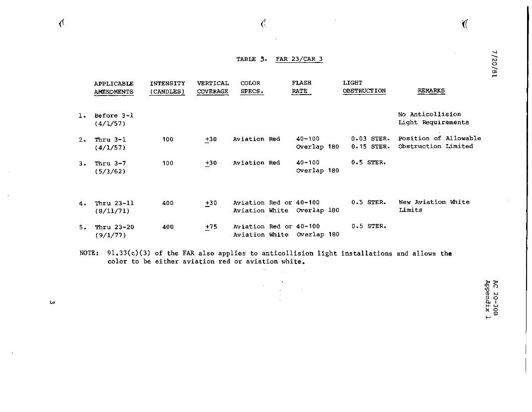
APPLICABLE INTENSITY VERTICAL COLOR FLASH LIGHT AMENDMENTS (CANDLES) COVERAGE SPECS. RATE OBSTRUCTION
1. Before 3-l No Anticollision (4/l/57) Light Requirements
2. Thru 3-1 (4/l/57)
3. Thru 3-7 (S/3/62)
100
100
400
400
+30 -
+30 -
+30 -
+75
Aviation Red 40-100 0.03 STER. Position of Allowable Overlap 180 0.15 STER. Obstruction Limited
Aviation Red 40-100 Overlap 180
0.5 STER.
4. Tbru 23-11 (8/11/71)
5. Thru 23-20 (9/l/77)
(I
TABLE 3. FAR 23/CAR 3
Aviation Red or 40-100 Aviation White Overlap 180
Aviation Red or 40-100 Aviation White Overlap 180
0.5 STER.
0.5 STER.
NOTE: 91.33(c)(3) of the FAR also applies to anticollision light installations color to be either aviation red or aviation white.
M
REMARKS
New Aviation White Limits
and allows the
w

c
APPLICABLE INTENSITY AMENDMENTS (CANDLES)
1. Before 4b-8 ( 5/16/5 3 1
2. Thru 4b-8 (5/16/53)
3. Thru 4b-3 (3/13/56)
4. Thru 4b-4 (4/l/57)
100
TABLE 4. FAR 25/CAR 4b
VERTICAL COLOR COVERAGE SPECS.
If Used Aviation Red
If Used Aviation Red
+30 Aviation Red -
FLASH RATE
If Used 40-100
If Used 40-100
40-100 Overlap 180
LIGHT OBSTRUCTION REMARKS
No Anticollision Light Requirements
If Used, On-Off ratio Not less than 1:75
If Used, On-Off ratio Not less than 1:75 If Extra Light Installed, No Flash Rate Limit in Overlaps
0.03 STER. Position of Allowable 0.15 STER. Obstruction Limited
5. Thru 25-27 400 +30 Aviation Red or 40-100 0.03 STER. New Aviation White - (8/11/71) Aviation White Overlap 180 0.15 STER. Limits
6. Thru 25-41 400 +75 Aviation Red or 40-100 0.03 STER. (9/l/77) Aviation White Overlap 180 0.15 STER.
NOTE: 91.33(c)(3) of the FAR also applies to anticollision light installations and allows the color to be either aviation red or aviation white.

TABLE 5. FAR ~~/CAR 6
APPLICABLE INTENSITY VERTICAL COLOR FLASH LIGHT AMENDMENTS (CANDLES) COVERAGE SPECS RATE OBSTRUCTION REMARKS
1. Before Part 6 (4/l/57)
No Anticollision Light Requirements
2. Thru 6-l (4/l/57)
3. Thru 6-5 (5/3/62)
100
100
+30 Aviation Red 40-100 0.03 STER. Overlaps 180
+30 Aviation Red 40-100 0.05 STER. - Overlaps 180
4. Thru 27-6 400 +30 Aviation Red or 40-100 0.5 STER New Aviation White (8/11/71) Aviation White Overlaps 180 Limits
5. Thru 27-10 150 +30 Aviation Red 40-100 0.5 STER. Aviation White not - (2/5/76) Overlaps 180 acceptable
NOTE: 91,33(c)(3) of the FAR also applies to anticolision light installations and allows the color to be either aviation red or aviation white.
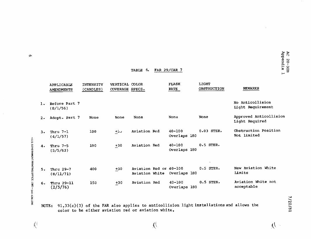
APPLICABLE INTENSITY AMENDMENTS (CANDLES)
1. Before Part 7 (8/l/56)
2. Adopt. Part 7 None None None None None
3. Thru 7-l (4/l/57)
4. Thru 7-5 (5/5/62)
5. Thru 29-7 (8/11/71)
6. Thru 29-11 (2/S/76)
NOTE: 91.33(c)(3) of the FAR also applies to anticollision lightinstallationsand allows the
100
100
400
150
TABLE 6. FAR 29/CAR 7
VERTICAL COLOR FLASH LIGHT COVERAGE SPECS. RATE OBSTRUCTION
+5, -
+30 -
+30 -
+30
Aviation Red 40-100 0.03 STER. Overlaps 180
Aviation Red 40-100 0.5 STER. Overlaps 180
Aviation Red or 40-100 0.5 STER. Aviation White Overlaps 180
Aviation Red 40-100 0.5 STER. Overlaps 180
REMARKS
No Anticollision Light Requirement
Approved Anticollision Light Required
Obstruction Position Not limited
New Aviation White Limits
Aviation White not acceptable
color to be either aviation red or aviation white.