advisory circular ac43-7 calibration of compasses and
TRANSCRIPT

Published by Civil Aviation Authority
PO Box 3555 Wellington 6140
Authorised by
Manager Policy & Regulatory Strategy
Advisory Circular AC 43-7
Revision 2
Calibration of Compasses and Surveying Compass Swing Sites
11 July 2014
General Civil Aviation Authority advisory circulars (ACs) contain information about standards, practices, and procedures that the Director has found to be an acceptable means of compliance with the associated rule.
Consideration will be given to other methods of compliance that may be presented to the Director. When new standards, practices, or procedures are found to be acceptable they will be added to the appropriate AC.
Purpose This AC describes an acceptable means of compliance with standards for the calibration of compasses and the surveying of compass swing sites.
Related Rules
This AC relates specifically to Civil Aviation Rule 91.605(e) (5).
Change Notice Revision 2 updates the general swing procedures.

Advisory Circular AC 43-7 Revision 2
11 July 2014 CAA of NZ 2
Table of Contents
Introduction ............................................................................................................... 3
Definitions .................................................................................................................. 3
Part 1 — Compass Calibration ...................................................................................... 3 Occasions for calibration...................................................................................................... 3 Demagnetisation................................................................................................................. 4 Compass calibration procedure ............................................................................................ 4
The compass calibration site ........................................................................................ 4 Preparation ................................................................................................................ 5
General swing procedures ................................................................................................... 6 Coefficient method ............................................................................................................. 7
Correcting swing......................................................................................................... 7 Calculate coefficient C ................................................................................................. 7 Calculate coefficient B ................................................................................................. 7 Calibration swing ........................................................................................................ 8 Calculate coefficient A ................................................................................................ 8 Residual deviation ...................................................................................................... 8
The quick method ............................................................................................................... 9 Air swings ........................................................................................................................... 9 Certification and recording .................................................................................................. 9
Part 2 — Compass Swing Site Surveying ..................................................................... 10 Introduction ..................................................................................................................... 10 Base requirements ............................................................................................................ 10 Base classifications ............................................................................................................ 11 Types of survey ................................................................................................................. 12 Survey methods ................................................................................................................ 12
General 12 Reciprocal bearing method ........................................................................................ 13 Distant bearing method ............................................................................................ 14 Surveying pole method ............................................................................................. 14 Magnetic intensity survey ......................................................................................... 15 Area survey .............................................................................................................. 21
Marking of base ................................................................................................................ 23

Advisory Circular AC 43-7 Revision 2
11 July 2014 CAA of NZ 3
Introduction
This AC provides standards acceptable to the Director for the calibration of direct reading and remote reading magnetic compasses. Alternative standards may be acceptable to the Director if they provide an acceptable level of safety.
This AC also provides standards acceptable to the Director for the surveying of compass swing sites, or compass pads, to establish their magnetic suitability for the calibration of compasses.
Definitions
For the purpose of this AC the following definitions apply—
Air swing means to conduct the inspection for the calibration of a compass during a flight detailed for this purpose.
Deviation means the angular difference between magnetic heading and compass heading.
Compensation means the correction of deviation caused by aircraft magnetism.
Calibration means the measurement of the deviation of a compass installed in an aircraft, any necessary compensation of this deviation, and the recording of the residual deviation.
Residual deviation means the deviation remaining after compensation.
Part 1 — Compass Calibration
Occasions for calibration Each installed compass should be calibrated:
• prior to the issue of an airworthiness certificate
• either:
o every 24 months when installed in an aircraft issued with an airworthiness certificate, unless the approved maintenance programme prescribes a different period; or
o at the period prescribed in the operator’s maintenance manual when installed in an air transport aircraft
Each compass should also be calibrated for out-of-phase occurrences, including:
• when initially installed or reinstalled in an aircraft
• after an engine change, unless the manufacturer prescribes otherwise
• whenever a magnetic sensing element has been changed or relocated
• after modification of an electrical or avionic installation of the aircraft, unless the certifying engineer is satisfied that the modification will not affect the compass
• after a lightning strike, unless at least four heading checks 90º apart shows that no change of deviation has occurred

Advisory Circular AC 43-7 Revision 2
11 July 2014 CAA of NZ 4
A heading check may be made during the flight on which a strike has occurred if this procedure is documented in the appropriate aircraft manual.
Refer to the section of this AC dealing with lightning strikes and aircraft demagnetisation.
• after any maintenance involving the addition, removal, or relocation of magnetic materials likely to influence compass deviation
Maintenance manuals may indicate the components that, if changed, would require the compass to be swung.
• following any operational occurrence, such as an accident, or heavy landing, that is likely to affect compass deviation
• after long-term storage of the aircraft
• whenever there is reason to suspect that a change of deviation may have occurred
A heading check should be made prior to take-off if magnetic cargo is being carried.
Demagnetisation Aircraft compass calibration can be affected by the magnetisation of the aircraft and its components. This magnetisation may be a result of residual magnetism of installed aircraft components or as result of a lightning strike. In the case of a lightning strike the disturbance can be very high and any demagnetisation should not be attempted until the aircraft is magnetically stable. Stabilisation can take several days.
A heading check may be sufficient during the flight on which a lightning strike has occurred if this procedure is detailed in the appropriate manuals.
If a simple heading check is insufficient then the aircraft should be demagnetised. Demagnetisation should be accomplished in accordance with the manufacturer’s recommendations.
After demagnetisation the aircraft should be flown twice, each flight for at least one hour, performing figure of eight manoeuvres on each of the main compass headings to stabilise the magnetism. The deviations should be calculated during these flights to determine the effectiveness of the demagnetising. The aircraft compass should be re-swung two months after the demagnetising to ensure that the aircraft is magnetically stable.
Compass calibration procedure Manufacturer’s procedures should be followed where prescribed. Where no manufacturer’s procedures are available the procedures in this AC provide a general compass swinging method.
The compass calibration site The compass of an aircraft should be calibrated only on a site that has been surveyed as being level and free from magnetic disturbances. In addition, the site selected should:
• be accessible
• not interfere with normal aircraft movements
• be large enough to accommodate the aircraft, considering:
o whether the aircraft will be towed or taxied to the site
o the radii of the aircraft’s turning circle
o the position of the heading points

Advisory Circular AC 43-7 Revision 2
11 July 2014 CAA of NZ 5
o the position of the aircraft’s sensor
• be useable in most weather conditions
• be marked with:
o the site centre
o the area in which the aircraft sensor should remain during the swing
o the points where the landing compass should be located
o areas of magnetic anomalies
o turning circles if applicable
If magnetic headings are marked on the site these headings should be checked at intervals not exceeding four years to ensure alignment with the magnetic meridian. The site should be rechecked for freedom from magnetic disturbances after any changes that are likely to affect the magnetic field at the site, including:
• the erection of buildings
• the installation of power lines above or below ground
• runway or pad reinforcing
• pipe lines
• any significant metallic changes to the area such as:
o fences
o drains
o scrap metal dumps
The survey of a compass swinging site involves the use of specific instruments, the taking of up to 300 readings, and may take several hours to complete. The site owner should resurvey the site:
• if the magnetic reliability of the site is in doubt
• every five years for a Class 1 site
• every two years for a Class 2 site
Full details of compass site surveying are in Part 2 of this AC.
Preparation Prior to calibration, the compass should be checked for general serviceability and it should be verified that angle of dip correction for the southern hemisphere has been made.
The compass should be calibrated with:
• engine(s) running
• all equipment correctly stowed for normal operation
• all doors closed
• flight controls as closely as practicable to cruise position
• aircraft systems operating for normal cruise configuration, including:
o electrical systems
Advisory Circular AC 43-7 Revision 2
11 July 2014 CAA of NZ 6
o navigation systems
o communications
Communications systems do not have to actually be transmitting or receiving during the calibration.
General swing procedures During compass calibration the aircraft should be positioned not more than 5 degrees from the required headings, and shall be calibrated to determine the residual deviation on at least eight equally spaced headings, that shall include the cardinal headings. The magnetic heading of the aircraft should be established by means of a landing compass or similar instrument, or by alignment with a marked compass site or known headings.
The flight controls should be operated and avionics systems switched on and off, or operated through the range permitted for cruising flight, to ascertain that there are no significant adverse effects.
When calibrating in accordance with the above procedures, the residual deviation should not exceed:
• 2º for a remote reading (gyro) compass
• 3º for a remote reading (non-gyro) compass
• 5º for a direct reading compass used as the primary heading reference
• 8º for any other compass

Advisory Circular AC 43-7 Revision 2
11 July 2014 CAA of NZ 7
Coefficient method Correcting swing The aircraft is positioned on each of the cardinal headings in the following order:
• north: record landing compass reading, aircraft compass reading and calculate deviation
• east: record landing compass reading, aircraft compass reading and calculate deviation
• south: record landing compass reading, aircraft compass reading and calculate deviation
Note: Deviation (DEV) = landing compass heading – aircraft compass heading
Calculate coefficient C
2devSdevNtCcoefficien −
=
For example:
• if the landing compass reads 358º and the aircraft compass reads 360º the deviation on north is –2º (devN)
• if the landing compass reads 177° and the aircraft compass reads 181° the deviation on south is –4° (devS)
( ) ( )2
42 −−−=tCcoefficien [Note: (-2) minus (-4) is the same as (-2) plus (+4) which equals (+2)]
122
+=
=
The sign for coefficient C should then be changed and applied to the aircraft compass, adjusting the N-S corrector to Make Compass Read (MCR), in this case 180° (181° – 1° = 180°). Then;
• west: record landing compass reading, aircraft compass readings and calculate deviation
Calculate coefficient B
2devWdevEtBcoefficien −
=
For example:
• if the landing compass reads 090º and the aircraft compass reads 090º the deviation on East is 0º (devE)
• if the landing compass reads 270° and the aircraft compass reads 274° the deviation on West is –4° (devW)
( ) ( )2
40 −−=tBcoefficien
224
+=
=

Advisory Circular AC 43-7 Revision 2
11 July 2014 CAA of NZ 8
The sign for coefficient B should then be changed and applied to the aircraft compass, adjusting the E-W corrector to Make Compass Read (MCR) in this case 272º (274° – 2° = 272°).
Calibration swing Following the adjustment for coefficients B and C, a calibration or check swing is carried out through eight successive points, the cardinal and quadrant headings, each 45° apart; namely:
315º, 000º, 045º, 090º, 135º, 180º, 225º, and 270º.
At each point the landing compass reading, aircraft compass reading and the deviations are recorded.
Calculate coefficient A
This should now be calculated using the following formula:
8devNWdevWdevSWdevSdevSEdevEdevNEdevNtAcoefficien +++++++
=
Note: This correction can’t be made to some compasses but where possible, the compass is rotated in its mounting to correct for coefficient A.
For example; with the aircraft compass showing north, physically rotate the compass in its mounting to correct for coefficient A, (the installation error). If the calculated deviation is positive, make the compass reading increase by that sum.
Residual deviation After physically adjusting the compass in its mount, to correct for coefficient A, we need to make a correction to the recorded deviations. This is achieved by subtracting the coefficient A figure, sign unchanged, from the individual deviation figures.
residual deviation = deviation – coefficient A
(Remember, minus a minus is a plus.)
Residual deviation is recorded on the correction card and used to calculate the “STEER” heading on the displayed compass card.
N NE
SE
E
SW S
W
NW
Advisory Circular AC 43-7 Revision 2
11 July 2014 CAA of NZ 9
The quick method Another method that does not involve calculating coefficients C or B is as follows:
• position aircraft onto north and completely remove the deviation with compensator
• position aircraft onto east and completely remove the deviation with compensator
• position aircraft onto south and half the deviation using the compensator
• position the aircraft onto west and half the deviation using the compensator
• complete the calibration or check swing, as described in the coefficient method, on all eight headings recording the deviations and adjusting for coefficient A
This procedure gives the same results as the coefficient method but avoids the calculation of coefficients B and C; and is much quicker.
Air swings For aircraft equipped with inertial reference navigation systems an air swing may be conducted to check and calibrate aircraft compasses. An air swing involves flying the aircraft on eight headings north, northeast, east, southeast, south, southwest, west, and northwest - established from the inertial system and checking the aircraft compass heading against these headings.
Airborne calibration of aircraft compasses should be conducted in accordance with the aircraft manufacturer’s approved procedures or other procedures acceptable to the Director.
Certification and recording When the residual deviation has been determined, a compass card should be displayed near the compass. If the maximum residual deviation does not exceed 1 degree, a placard to this effect may be displayed instead of a correction card. The correction card should be either graphical or tabular (For/Steer) in format, and must show its expiry date.
After a compass has been calibrated an aircraft logbook entry should be made that includes full details of the calibration, correction card, and any placarding.
A release to service should be certified in accordance with Part 43.

Advisory Circular AC 43-7 Revision 2
11 July 2014 CAA of NZ 10
Part 2 — Compass Swing Site Surveying
Introduction In carrying out a swinging procedure for direct-reading and remote-reading compasses, the primary objective is to determine the deviations caused by the magnetic field components of an aircraft. It is, therefore, necessary for swinging to be undertaken at a location where only these aircraft field components and the earth’s magnetic field, can affect the readings of compasses. The location should be carefully chosen and surveyed to prove that it is free from any interfering local magnetic fields and also to establish it as the base on which all aspects of swinging procedures are to be carried out. The effect of interfering fields is to cause distortion of the direction and intensity of the earth's field. The effects on direction are the most critical and it is therefore necessary for these to be determined during a survey. Any significant effects on the horizontal intensity will be detected as a change in direction, if suitable procedures are employed.
The Civil Aviation Authority does not carry out surveys or approve compass bases. However this compass swing site surveying procedure is an acceptable means of ensuring the overall accuracy of aircraft compasses. Surveys may be carried out by an operator or by an airport authority.
Base requirements A compass base should meet the following minimum requirements.
• It should be accessible, reasonably level in all directions and its use should not interfere with normal aircraft movements on the airport.
• It should be free from magnetic fields, other than that of the earth, which might cause aircraft compass errors. Most surface causes of errors are obvious – buildings and installations containing ferromagnetic components such as wire fences, drain and duct covers, picket points and lighting installations. The most likely underground causes of magnetic interference are:
o buried scrap metal and old brickwork
o reinforced concrete
o pipelines including drainage systems
o magnetic soil and rocks
o electrical cables, conduits, and airfield lighting transformers
o ferromagnetic pipes
If such items are found at the selected location they should be removed if possible. Even though the area may be within permitted maximum limits of deviation it is recommended that any ferromagnetic material present should still be removed as its magnetic effect may change with time and thereby down-grade the accuracy of the base. Where electrical cables cannot be avoided, their effects, with and without current flowing, must be checked at intervals along their length, especially around known joints.
If a new base is being constructed great care must be taken to ensure that the area is not magnetically contaminated after survey and during construction. Steel reinforcing should obviously be avoided and any aggregate or hard-core used in the foundations should not be magnetic or contain magnetic items such as steel wire or drums, bricks, boiler clinker, blast furnace slag or magnetic rock. All steel shuttering and associated pins used when laying concrete should be removed. On completion of all work a full survey must be repeated.

Advisory Circular AC 43-7 Revision 2
11 July 2014 CAA of NZ 11
• A base should be sited so that its datum circle is at least 50 metres away from hangars and other steel-framed buildings and at least 100 metres away from buildings containing electrical power generation and distribution equipment and also from overhead or underground power cables.
Proposed building programmes should be examined to ensure that the site is not scheduled for other work.
• A base should be large enough and of such load-bearing strength as to take all types of aircraft for which it is likely to be used. In this connection, some important factors to be considered are:
o whether an aircraft will be towed or taxied during the swing
o the radii of the turning circles of the aircraft
o the position of sighting rods and target fixtures on the aircraft and their likely path during the swing
o the likely positions of flux detector units of remote-reading compass systems
• The surface of the base should not preclude its use in wet weather.
• The base should be clearly and permanently marked to show:
o the base centre
o the central area in which a direct-reading compass, or flux detector unit of a remote-reading compass system, should remain during the swing
o areas of magnetic anomalies that cannot be removed
o nose-wheel turning circles
o if the base is to be used for carrying out electrical swings a north-south line should be painted on the base, together with markings to indicate the locations of the compass calibrator monitor and turntable, and the bearing of the reference target used, when sighting the monitor.
Paint is the best medium for marking concrete. The datum compass circle, which may be on grass, should be marked permanently with a narrow continuous path of non-magnetic material such as tarmac or gravel.
Base classifications Compass bases may be established as either Class 1 or Class 2, the difference between them being only in the limits of permitted maximum deviation to be found anywhere within the base area as follows.
• Class 1
The maximum permissible deviation is ± 0.1º.
Bases of this accuracy are required for carrying out refined swings – swinging of aircraft in which remote-reading compasses are used as magnetic heading reference systems, in conjunction with such equipment as doppler systems.
• Class 2
The maximum permissible deviation is ± 0.25º.
Bases of this accuracy are suitable for carrying out standard swings – swinging of aircraft in which the primary heading reference is provided by a remote-reading compass system, with a direct-reading compass serving as a standby.

Advisory Circular AC 43-7 Revision 2
11 July 2014 CAA of NZ 12
A location where the permissible deviation is greater than ±0.25º may be used where a direct-reading compass is used as the primary heading reference.
Types of survey The following types of survey are normally carried out to assess the suitability of a location at which a compass base is to be finally established.
• Initial survey
This is the first assessment survey of a location to determine gross errors and should be carried out by the aircraft operator or airport authority. If the deviations obtained appear to be within the permissible limits laid down for Class 1 and Class 2 bases there is justification for carrying out an establishment survey.
• Establishment survey
This survey is of a more detailed nature in that measurements are taken at a greater number of more closely spaced points. The aircraft operator or airport authority may also carry out the survey but, where appropriate, it is recommended that the services of a specialist be engaged.
• Periodic re-survey
After a base has been established a detailed re-survey should be carried out at the following intervals:
• Class 1 – every 5 years
• Class 2 – every 2 years
• Annual check
All bases should be checked annually to ensure that markings and boundaries are clearly defined and that no work has been done which might affect their magnetic properties. Changes in magnetic variation should also be taken into account. If any doubt exists the suspect area should be given a detailed magnetic survey.
• Area survey
An area survey is normally confined to the selection of a location that is to be used for carrying out a more specialised form of compass calibration procedure known as an electrical swing.
Survey methods General
Methods Survey methods are divided into the following:
• reciprocal bearing method – requires the use of accurate magnetic bearing compasses of either the medium landing type or the high-precision datum type to determine the effects of interference from local magnetic fields
• distant bearing method – requires the use of accurate magnetic bearing compasses of either the medium landing type or the high-precision datum type to determine the effects of interference from local magnetic fields
• surveying pole method – lower order of accuracy and its use should be limited

Advisory Circular AC 43-7 Revision 2
11 July 2014 CAA of NZ 13
• magnetic intensity survey methods – modern method of measuring the magnitude of the magnetic field and checking for anomalies
• area surveys – specific procedure for electrical swinging
Checking and correction of survey instruments Before carrying out a survey, the appropriate survey instruments should be given the full serviceability checks prescribed in the relevant operating manual, paying particular attention to checks that affect the repeatability of readings such as pivot friction. Reference should also be made to any associated instrument test certificates to ascertain any instrument errors requiring correction. When the reciprocal bearing method is used, bearings should be taken on a distant object with both compasses to establish a correction that can be applied to every reading taken from one of the compasses.
Positioning of survey instruments In order that the deviation limits of a chosen location may be accurately assessed for base classification purposes from an establishment survey, the survey instruments should be set up at close regular intervals – every 6 metres – to cover the area quadrant by quadrant. The instruments should be at the maximum height of its tripod that is approximately 1.5 metres. In most types of aircraft, direct-reading compasses and flux detector units of remote-reading compasses are above this height. If a base is also to be used for an aircraft the compasses and detector units of which are below 1.5 metres, assessment should then be made closer to the ground.
At certain stages of an area survey procedure, assessments are made with the tripod set at both minimum and maximum heights.
Reciprocal bearing method This method is the most accurate and may be adopted for an initial assessment survey, a detailed establishment survey and a periodic re-survey. It requires the use of two precision datum compasses; one being designated the master compass and the other the mobile compass.
The procedure is as follows.
• Following the checks for serviceability, both compasses should be aligned to a common magnetic datum. This is done by setting the compasses up, in turn, on a tripod positioned as near to the anticipated centre of the base as is practical and sighting the compass on a distant object and noting, for each compass, the average of several determinations of the magnetic bearing. This produces the correction that is subsequently applied to the readings of the mobile compass. Frequent checks on the accuracy of this correction should be made throughout the subsequent stages of the survey procedure.
• The master compass and tripod should be kept in its original position and the mobile compass and its tripod should be positioned at various points around the area to give good coverage. At each point, the two compasses are aligned on each other's sighting telescope object lenses.
• When the compasses are aligned, bearings should be taken from the bearing plates of the compasses and the magnetic deviation between the two compass positions should be obtained by taking the difference between bearing plate readings and subtracting 180º. The sign convention used for the deviation is that, if the reading of the mobile compass is greater than that of the master compass, the deviation is negative. Conversely, the deviation is positive if the master compass reading is greater than that of the mobile compass.

Advisory Circular AC 43-7 Revision 2
11 July 2014 CAA of NZ 14
• The deviations should be recorded on an observation log, which should take the form of a scaled diagram of the area. The positions of any objects in the area such as drains, cable duct covers, lights, and picketing points should also be indicated on the log. Areas in which deviations are in excess of the limits permitted by the appropriate base classification should be investigated and, where possible, the source of magnetic interference should be eliminated. Where magnetic interference cannot be eliminated the area should also be indicated on the observation log as a prohibited area – an area that must be avoided when positioning an aircraft and landing compass for the purpose of swinging.
• Care should be taken to ensure that there are no obvious magnetic objects near the chosen centre of the base. If the deviations are such that their mean is more than half the deviation limits for the class of base being surveyed, it should be assumed that there is a buried object near the base centre.
Distant bearing method This method should be used only for initial surveys and for gross error checks of Class 2 bases carried out because of doubts raised during annual checks.
The procedure is as follows.
• Select a distant object at least 2 nautical miles away and accurately locate its position and the position of the compass base on a larger scale map and measure the distance between them. Mark the line of sight from the centre of the compass base to the distant object.
• Calculate the angular correction to be applied to bearings taken away from the base centre using the formula:
Lateral distance from line of sight x 180
Correction Angle = Degrees Distance to the object x π
• After ensuring that there are no objects in the area of the base centre likely to have a magnetic influence, the bearing compass, which may be of the medium landing type or precision datum type, should be set up and a datum bearing obtained by measuring the bearing of the distant object.
• Take bearings of the distant object from selected points around the base area and after applying the calculated corrections, compare the bearings with the datum bearing. Any difference obtained will be due to deviations present, assuming that the base centre is free from deviation. The deviations should be recorded on an observation log.
Surveying pole method This method is simpler than those already described and requires the use of two poles similar to those used by a land surveyor and in addition, a medium landing compass. Its survey accuracy is, however, of a lower order, principally because it does not utilise magnetic bearings of distant objects as a datum. The use of this method should therefore be restricted to the surveying of locations at which deviation limits outside those permitted under Class 1 or Class 2 are acceptable, such as:
• a location for swinging aircraft using direct-reading compasses as the primary heading reference
• the initial assessment of gross errors prior to a detailed establishment survey of a base and where, in the absence of an established Class 1 or Class 2 base or more accurate surveying equipment, a swing is necessary to enable an aircraft to undertake a positioning flight
The procedure is as follows.

Advisory Circular AC 43-7 Revision 2
11 July 2014 CAA of NZ 15
• One surveying pole should be placed in the centre of the area chosen and the medium landing compass should be positioned and levelled 10 metres to the south of the pole. A plumb bob should be suspended from the centre of the compass to the ground and the sighting device should be set to read due north. The second pole should be positioned 10 metres to the north of the centre pole, so that, when viewed with the compass sights as set, the two poles are in alignment.
• The plumb bob position should be marked with a peg or a painted mark and the position of the second pole and the compass should be interchanged. The compass reading with the poles as now positioned should be checked and should be within ± 1º of the reciprocal of the initial reading.
• A further check should be made by moving and sighting the compass along a line between the north and south points already obtained, taking at least four readings at approximately equidistant intervals. The compass should not deviate by more than 1º from the original reading at any position.
• The same procedure should be followed for determining the east and west positions.
• The geometric location of the cardinal points should be proved by checking the chord distances between the points, as indicated by pegs or painted marks. If they are equal then the north-south and east-west lines are at right angles. In any case, the measurements should agree within ± 75 mm.
• The whole of the foregoing procedure should be followed for determining deviations in the inter-cardinal areas and in the area around which the compass is to be positioned during the swinging procedure.
Magnetic intensity survey An alternative to the direct reading of declination from compasses is the measurement of the magnitude of the magnetic field to determine whether a site is suitable for testing aircraft compasses. This survey requires specialist knowledge of techniques of measurement and analysis of magnetic fields. This AC provides some background as to the theory and application of the method.
Variations in the magnetic field By the very nature of magnetic fields, it is impossible for variations to occur in one component of a magnetic field across a plane area – external to the source of the field – without variations occurring in other components. Since a dipole field can approximate the field at a distance from a localised source, this method considers the fields from buried dipole sources and determines the maximum variation that can occur in declination for a given variation in the magnitude of the magnetic field. If a survey of the magnitude of the magnetic field shows no variations greater than an appropriate value then the site should be considered suitable for aircraft compass testing.
Standards for magnetic instruments used in surveys As the magnetic field is a vector, to fully quantify it requires measuring both its magnitude and direction. The most common instruments used at magnetic observatories to make these measurements are a proton magnetometer to measure the magnitude of the vector and a D-I fluxgate to measure its direction.
Proton magnetometer A proton magnetometer measures the precession frequency of a proton in the earth's magnetic field using a crystal oscillator. The precession frequency is related to the field strength by the gyromagnetic ratio of a proton. The gyromagnetic ratio of a proton is an atomic constant and has been determined and a value for it is quoted as

Advisory Circular AC 43-7 Revision 2
11 July 2014 CAA of NZ 16
“2.875196 x 10⁸ s-1 T-1 with a standard error of 3 parts in 106”.
For survey work, the absolute accuracy of a proton magnetometer is not critical, as long as the instrument is stable during the course of the survey. Only variations in the field inside the surveyed area are of concern, and not the absolute value of the field.
D-I fluxgate magnetometer A D-I fluxgate magnetometer consists of a fluxgate sensor mounted on the telescope of a nonmagnetic theodolite. In use the telescope is rotated until the output from the fluxgate sensor is zero. In this position, the axis of the fluxgate sensor is perpendicular to the direction of the earth’s magnetic field. By observing a number of different null positions, it is then possible to determine the plane perpendicular to the earth’s magnetic field and hence the direction of the field itself. By using an appropriate sequence of observations, it is possible to eliminate the effect of various offsets in the instrument.
In particular, the following offsets associated with the fluxgate sensor are removed from the final results:
• a zero offset in the sensor and its associated electronics
• any misalignment of the axis of the sensor to the telescope in both the horizontal and vertical directions
The sequence of observations also removes standard errors associated with the theodolite itself.
Using this procedure:
• for proton magnetometers, providing the crystal reference oscillators in the magnetometers are set correctly, then the readings should be accurate to within 4 parts in 105
• for declination and inclination magnetometers, if two or more independent instruments agree the results of individual readings should be accurate to within 1’ of arc in both declination and inclination
Dipole nature of sources of disturbance The source of any disturbance to the earth's magnetic field at the site can be assumed to be of limited local extent. Any extended source of disturbance would be recognisable and a separate analysis or extra measurements should be made to check the suitability of the site.
The magnetic field from an isolated source can be expressed as the sum of spherical harmonic terms starting with a dipole term and then higher order terms. The field from the dipole term decays as 1/r3 and the field from higher order terms decays more rapidly. Thus the field from an arbitrary source will be approximately a dipole field at distances greater than the size of the source from the source. In practice, the dipole term will be larger than higher order multi-pole terms for an isolated source. This is the case whether the magnetisation is from a permanent magnetisation or an induced magnetisation.
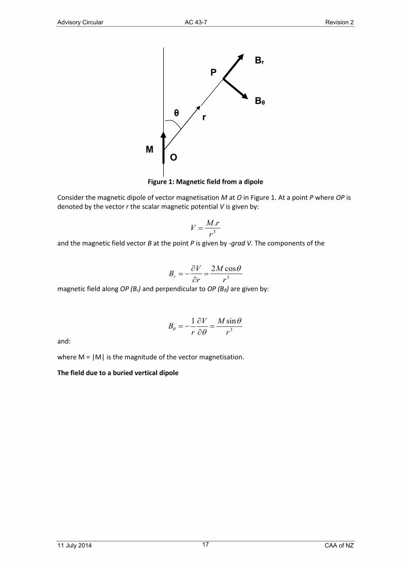
Effects on declination and magnitude of the earth's field from buried dipoles The field due to a dipole source
Advisory Circular AC 43-7 Revision 2
11 July 2014 CAA of NZ 17
Figure 1: Magnetic field from a dipole
Consider the magnetic dipole of vector magnetisation M at O in Figure 1. At a point P where OP is denoted by the vector r the scalar magnetic potential V is given by:
and the magnetic field vector B at the point P is given by -grad V. The components of the
magnetic field along OP (Br) and perpendicular to OP (Bθ) are given by:
and:
where M = |M| is the magnitude of the vector magnetisation.
The field due to a buried vertical dipole
O M
r Bθ
Br P
θ
3.
rrMV =
3cos2r
MrVBr
θ=
∂∂
−=
3sin1r
MVr
B θθθ =∂∂
−=

Advisory Circular AC 43-7 Revision 2
11 July 2014 CAA of NZ 18
Figure 2: Magnetic field from a vertical buried dipole
Consider a buried vertical dipole of magnetic moment M at a distance h below the survey height as shown in Figure 2. The field from the dipole at the survey point P can be resolved into
components Bv and Bh where:
and:
The maximum value of Bv is 2M/h3 which occurs directly above the dipole where θ = 0. At this point Bh = 0 so the change in the magnitude of the earth's magnetic field due to the dipole is 2M/h3 sin I, where I is the inclination of the earth's magnetic field. The maximum change in the magnitude of the field (δF) must be at least this value.
The maximum value of Bh occurs where:
so:
so:
O M
r
Bθ
Br P
θ h
Bv
Bh
( )θθθθθθ θ35
33
2
3
2
coscos3sincos2sincos −=−=−=hM
rM
rMBBB rV
θθθθθθ θ sincos3sincos3cossin 433 h
MrMBBB rh ==+=
( ) 0cossincos43 5233 =+−= θθθ
θ hM
ddBh
4cos5 2 =θ

Advisory Circular AC 43-7 Revision 2
11 July 2014 CAA of NZ 19
and:
and the maximum value of Bh is:
so that for a vertical dipole:
or:
The field due to a buried horizontal dipole
Consider a buried horizontal dipole of magnetic moment M at a distance h below the survey height as shown in Figure 3. The field from the dipole at the survey point P can be resolved into
components Bv and Bh where:
and:
54cos2 =θ
51sin2 =θ
52548
3hM
maxmaxmax sin23.2sin24
525hh BIBIF =≥δ
mzxh FI
B δsin
448.0max ≤
3
2
3
2 sincos2sincosr
Mr
MBBB rhφφφφ φ −=−=
( ) ( )φφφφφ 23
322
3
3
sin32sinsincos2sin−=−=
hM
hM
φφφφφφ φ cossin3cossin3cossin 433 h
MrMBBB rv ==+=

Advisory Circular AC 43-7 Revision 2
11 July 2014 CAA of NZ 20
Figure 3: Magnetic field from a horizontally buried dipole
The magnitude of Bh is a maximum directly above the dipole where ϕ = 90° and its value there is M/h3. The maximum value of Bv occurs when:
that is when:
and:
so that:
A horizontal dipole has a maximum effect on the declination when the dipole is oriented magnetic east-west. In this case the horizontal component of the magnetic field due to the dipole is perpendicular to the earth's magnetic field at the point where Bv is a maximum. The change to the magnitude of the magnetic field at this point is then Bvmax.sin I. The maximum effect on the magnitude of the magnetic field must be at least this large so that for a horizontal dipole:
or:
maxmaxmax sin858.0sin525
48hh BIBIF =≥δ
52548
3max hMBv =
54sin2 =φ
51cos2 =φ
( ) 0sincossin43 5233 =−= φφφ
φ hM
ddBv

Advisory Circular AC 43-7 Revision 2
11 July 2014 CAA of NZ 21
Minimum change in the magnitude of the magnetic field for a given change in declination Considering the effect on the magnitude of the magnetic field for a vertical or horizontal oriented dipole, it is seen that the smallest effect for a given horizontal perturbation to the earth's magnetic field occurs when the dipole is horizontal. The effect on declination will be a maximum if the dipole is oriented magnetic east-west.
A 0.1º degree variation in declination requires a horizontal perturbation to the magnetic field of H sin 0.1º which will be accompanied by a variation in the magnitude of the magnetic field of at least 0.858 H sin 0.1º sin I.
Typical results for New Zealand airports have been found to be:
Airport Auckland Christchurch
Horizontal intensity 25000 nanoTesla 21000 nanoTesla Inclination 63˚ 69˚ Minimum effect in magnitude of magnetic field for 0.1˚ variation in declination
33 nanoTesla 29 nanoTesla
Minimum effect in magnitude of magnetic field for 0.25˚ variation in declination
83 nanoTesla 73 nanoTesla
In practice Each individual site should be assessed and the variation in magnitude assessed to determine the conformity of the field over the compass swing site. Variations within the maximum calculated would indicate that the site is suitable for compass swings to be carried out.
Area survey This survey is carried out using the monitor and console control units of a compass calibrator set that is also designed for the electrical swinging of remote-reading compass systems. In this type of survey the principal objectives are to:
• determine the direction and strength of the earth's magnetic field at the locations of aircraft flux detector units (detector unit location check)
• select the point at which the compass calibrator monitor unit should be located in order to carry out an electrical swing (monitor location check)
• mark out the monitor and turntable location points and also a north-south line over which an aircraft must be positioned during a swing
The full setting-up procedures and operating instructions are detailed in the calibrator operating manual and reference to this document should be made. The following is general information only.
Detector unit location check The purpose of this check is to determine the uniformity not only of direction, but also the strength of the earth's field at points of the compass base that will correspond to the locations of detector units — the vertical stabiliser or wing tips of an aircraft. The strength of field is determined in order to obtain certain voltage values which must be set up in the calibrator
maxmax sin166.1 F
IBh δ≥

Advisory Circular AC 43-7 Revision 2
11 July 2014 CAA of NZ 22
control console unit during an electrical swing procedure to simulate the earth's field. The monitor and console control units are electrically interconnected by the appropriate cables and are set up within 3 to 4.5 metres of each other. Magnetic direction and strength is measured in both the vertical and horizontal planes.
The procedure is as follows.
• Measurements in the vertical plane
o Measurements are taken with the monitor mounted on its tripod, adjusted firstly to the minimum height position and then to the maximum height position.
o Direction is determined in each position of the tripod by setting the monitor on each of the four cardinal headings and noting the difference between these headings and the headings recorded on the control console unit.
o The average of the errors (the algebraic sum divided by four) is recorded as the monitor index error.
o The difference between the index errors at the minimum and maximum height positions is then calculated. If the difference exceeds the specified value (6 minutes is a typical value) the area surveyed is unsuitable.
o Field strength is determined at the minimum and maximum height positions of the monitor tripod by setting the monitor to a heading of zero degrees and obtaining voltage values from settings made on the control unit.
• Measurements in the horizontal plane
o Measurements are carried out to determine the uniformity of the earth's field direction and strength over a circle of 1.5 metres radius, the centre of which is at the location of the flux detector unit on the aircraft.
o The readings are taken at the centre of the circle with the monitor tripod at its normal operating height and with the monitor set, in turn, on each of the four cardinal headings. The differences between monitor and control console unit headings are then noted and a monitor index error obtained in the same manner as that described in the vertical plane.
o Readings are then taken on the cardinal headings with the monitor and tripod positioned, in turn, at four equidistant points on the perimeter of the circle and corresponding monitor index errors are obtained.
o The algebraic difference between these errors and the index error at the centre of the circle is then calculated and should be within the limits ±6 minutes.
o Field strength is determined by setting the monitor to a heading of zero degrees and obtaining voltage values with the monitor at the centre of the circle and at the four equidistant points on its perimeter.
Monitor location check The purpose of this check is to select the location for the monitor in order to measure the earth's field during the electrical swinging procedure. The location selected should be such that with an aircraft positioned on the base the magnetic effects of the aircraft itself will not influence the monitor readings. A distance of 25 to 30 metres is normally sufficient.
The procedure is as follows.

Advisory Circular AC 43-7 Revision 2
11 July 2014 CAA of NZ 23
• The direction and strength of the earth's field is determined at the selected location and corresponding monitor index error and voltage values, calculated.
• The bearing of a reference target at least 800 m distant from the location is also obtained. As this target is to be used during a compass swing it should be ensured that it would be visible from the monitor location when an aircraft is positioned on the base.
• The suitability of the selected monitor location is then determined by re-positioning the monitor at the flux detector unit location and measuring the direction and strength of the earth's field and then calculating the algebraic difference between values at each location.
• The readings at each location should be taken within a time of 30 minutes of each other to lessen the possibility of a change in the earth's field.
Marking of base On completion of the foregoing checks, markings must be permanently set out on the base to indicate the following.
• Location of flux detector units:
o for aircraft the flux detector units of which are installed in the vertical stabiliser, the marking is made on the north–south line
o for aircraft the flux detector units of which are installed in each wing tip, the markings are made each side of the north-south line at distances corresponding to those from the aircraft centre line.
• Location of monitor
o in addition to the location of the monitor itself, the bearing of the reference target used during the survey should also be marked at the monitor location.
• North-south line
o This line should be marked out from a point that is used as a reference in determining the flux detector unit location. The monitor is set up over this point and by lowering the monitor telescope so that its graticules are observed against the base, several other points are marked out:
firstly with the monitor on a corrected zero degree heading
secondly with the monitor on a heading of 180º
o A painted line then joins the points.