advancing pressure gain combustion in terrestrial … library/events/2015/utsr/wednesday... ·...
TRANSCRIPT
Advancing Pressure Gain
Combustion in Terrestrial
Turbine Systems
Steve Heister and Carson Slabaugh
Purdue UniversitySchool of Aeronautics and Astronautics
Maurice J. Zucrow Laboratories

11/03/2015 22015 University Turbine Systems Workshop
PGC Technology for Terrestrial Turbine Systems
Introduction
● Challenges to Overcome
o Combustion ‘Instability’
o Materials Considerations
o Component Integration
o Pollutant Emissions
o Cost
● Potential for large, single-technology gains in cycle efficiency
o 4-7% for simple cycles
o 1-3% in combined cycles
● Several Flavors of PGC
o CV deflagrative devices
o PDEs
o RDEs
GE FlexEfficiency Combined Cycle Power Plant
Purdue High Pressure Rocket RDE Testing
11/03/2015 32015 University Turbine Systems Workshop
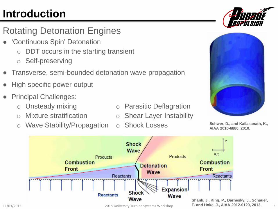
Rotating Detonation Engines
Introduction
Shank, J., King, P., Darnesky, J., Schauer,
F. and Hoke, J., AIAA 2012-0120, 2012.
Schwer, D., and Kailasanath, K.,
AIAA 2010-6880, 2010.
● High specific power output
● ‘Continuous Spin’ Detonation
o DDT occurs in the starting transient
o Self-preserving
● Transverse, semi-bounded detonation wave propagation
● Principal Challenges:
o Unsteady mixing
o Mixture stratification
o Wave Stability/Propagation
o Parasitic Deflagration
o Shear Layer Instability
o Shock Losses

11/03/2015 42015 University Turbine Systems Workshop
Current RDE Research Landscape in the USA
Introduction
● Industry
o Aerojet-Rocketdyne
o General Electric
o GHKN
o United Technologies
● Government
o AFRL, Wright-Patterson AFB
o DOE, NETL
o NASA, Glenn Research Center
● Academia
o Naval Postgraduate School
o Penn State University
o Purdue University
o University of Colorado, Boulder
o University of Maryland
o University of Michigan
o University of Texas, Arlington
Fotia et al., SciTech, 2015
R. Zhou and J.-P. Wang.,
Combustion and Flame, 2012
11/03/2015 52015 University Turbine Systems Workshop
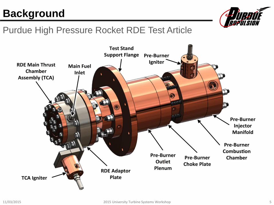
Purdue High Pressure Rocket RDE Test Article
Background
11/03/2015 62015 University Turbine Systems Workshop
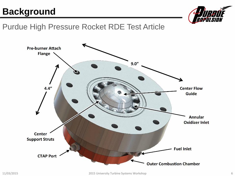
Background
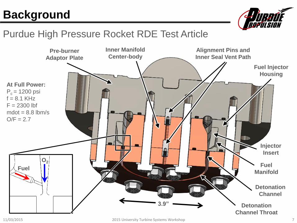
Purdue High Pressure Rocket RDE Test Article
11/03/2015 72015 University Turbine Systems Workshop
Fuel
Manifold
Detonation
Channel
Injector
Insert
Detonation
Channel Throat
Fuel Injector
Housing
Inner Manifold
Center-bodyPre-burner
Adaptor Plate
3.9”
At Full Power:
Pc = 1200 psi
f = 8.1 KHz
F = 2300 lbf
mdot = 8.8 lbm/s
O/F = 2.7
Alignment Pins and
Inner Seal Vent Path
O2
Fuel
Background
Purdue High Pressure Rocket RDE Test Article

11/03/2015 82015 University Turbine Systems Workshop
Background
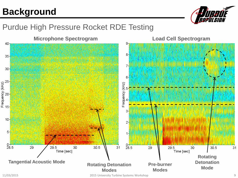
Purdue High Pressure Rocket RDE Testing
11/03/2015 92015 University Turbine Systems Workshop
Tangential Acoustic ModeRotating Detonation
Modes
Microphone Spectrogram Load Cell Spectrogram
Pre-burner
Modes
Rotating
Detonation
Mode
Background
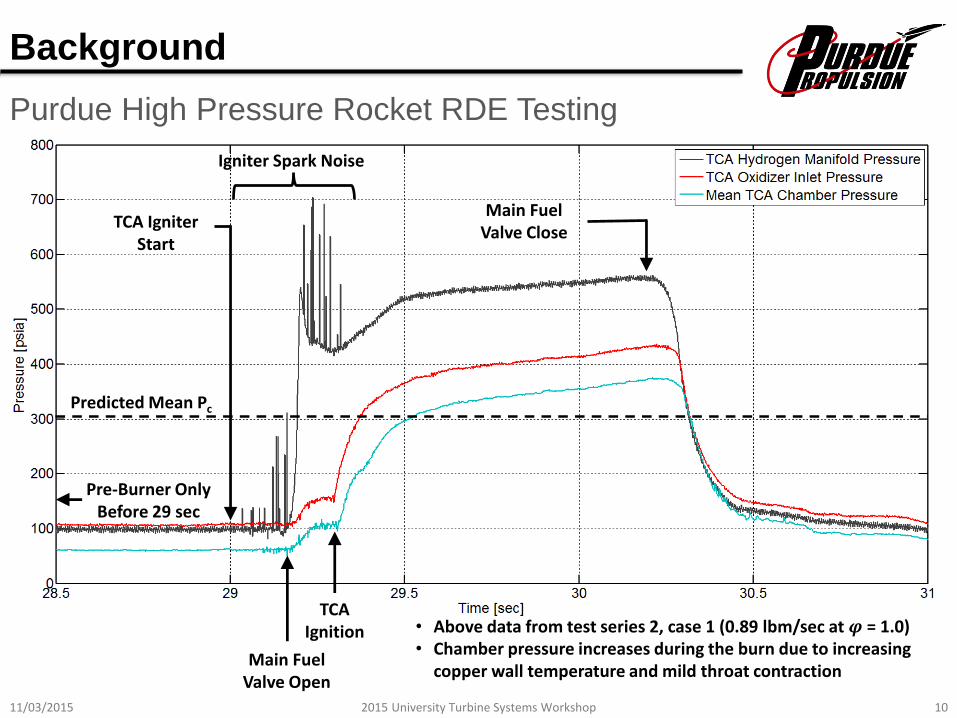
Purdue High Pressure Rocket RDE Testing
11/03/2015 102015 University Turbine Systems Workshop
Main Fuel Valve Open
TCA Ignition
Main Fuel Valve Close
TCA Igniter Start
Pre-Burner Only Before 29 sec
• Above data from test series 2, case 1 (0.89 lbm/sec at 𝝋 = 1.0)• Chamber pressure increases during the burn due to increasing
copper wall temperature and mild throat contraction
Igniter Spark Noise
Predicted Mean Pc
Background
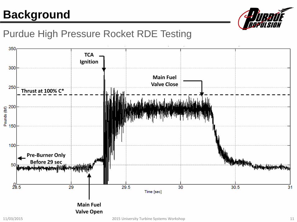
Purdue High Pressure Rocket RDE Testing
11/03/2015 112015 University Turbine Systems Workshop
Main Fuel Valve Open
Main Fuel Valve Close
TCA Ignition
Thrust at 100% C*
Pre-Burner Only Before 29 sec
Background
Purdue High Pressure Rocket RDE Testing

11/03/2015 122015 University Turbine Systems Workshop
Objectives
Purdue-UTSR Project Overview
Motivation
1) To develop scientific understanding of processes within an RDE, specifically
those relating to application-related challenges.
2) To translate that understanding into the design RDE hardware for improved
performance at representative cycle conditions
1) Characterize the performance of injection/mixing systems in an RDE using an
optically-accessible, linear platform with and advanced diagnostic methods
2) Establish an experimental methodology to assess pressure gain utilizing coupled
global and local measurements performed at conditions relevant to terrestrial
turbine systems (up to a P3 and T3 of 2.0 MPa and 800 K, respectively)
3) Evaluate the operation of an RDE combustion chamber over range of operating
conditions
4) Quantify pollutant emission production over a wide range of operability
11/03/2015 132015 University Turbine Systems Workshop
Team
Purdue-UTSR Project Overview
Swanand Sardeshmukh, Postdoctoral Researcher
Steve Heister, Raisbeck Distinguished Professor (co-PI)
Brandon Kan, Ph.D. student
Kyle Schwinn, Ph.D. student
Adam Holley and Chris Greene, UTRC advisors
Carson Slabaugh, Assistant Professor (co-PI)

11/03/2015 142015 University Turbine Systems Workshop
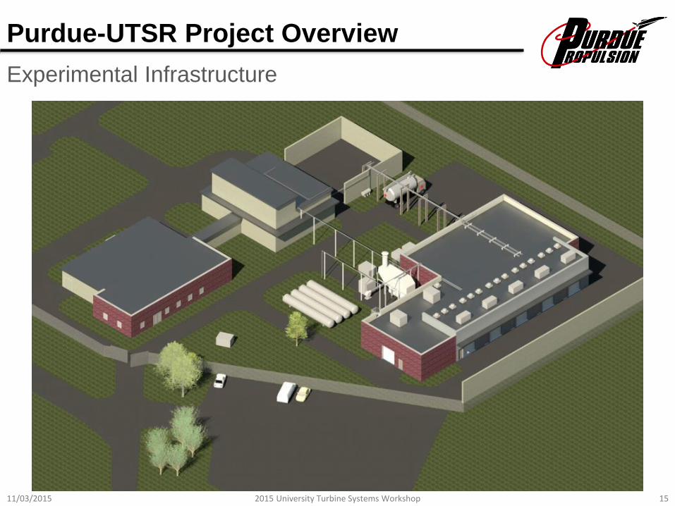
Experimental Infrastructure
Purdue-UTSR Project Overview
11/03/2015 152015 University Turbine Systems Workshop
Experimental Infrastructure
Purdue-UTSR Project Overview

11/03/2015 162015 University Turbine Systems Workshop
Experimental Infrastructure
Purdue-UTSR Project Overview
11/03/2015 172015 University Turbine Systems Workshop
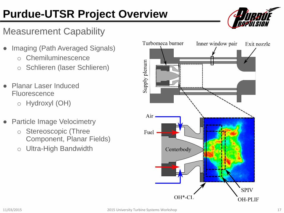
Measurement Capability
Purdue-UTSR Project Overview
● Imaging (Path Averaged Signals)
o Chemiluminescence
o Schlieren (laser Schlieren)
● Planar Laser Induced Fluorescence
o Hydroxyl (OH)
● Particle Image Velocimetry
o Stereoscopic (Three Component, Planar Fields)
o Ultra-High Bandwidth
11/03/2015 182015 University Turbine Systems Workshop
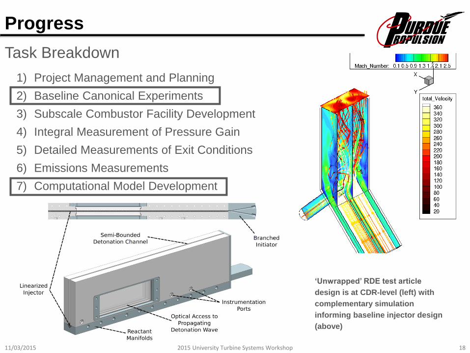
Progress
Task Breakdown
1) Project Management and Planning
2) Baseline Canonical Experiments
3) Subscale Combustor Facility Development
4) Integral Measurement of Pressure Gain
5) Detailed Measurements of Exit Conditions
6) Emissions Measurements
7) Computational Model Development
‘Unwrapped’ RDE test article
design is at CDR-level (left) with
complementary simulation
informing baseline injector design
(above)
11/03/2015 192015 University Turbine Systems Workshop
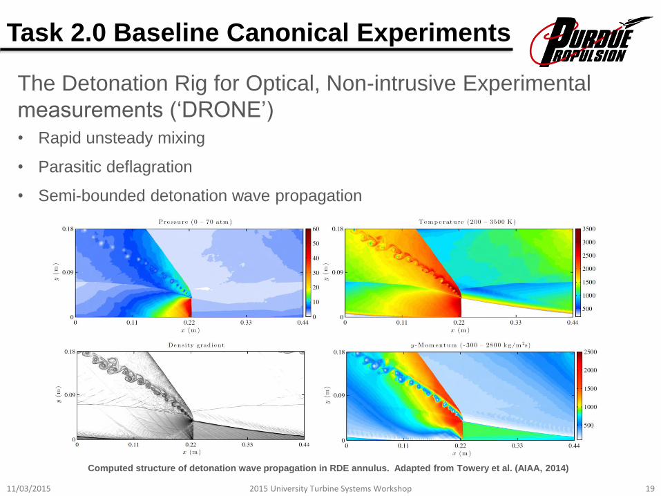
The Detonation Rig for Optical, Non-intrusive Experimental
measurements (‘DRONE’)
• Rapid unsteady mixing
• Parasitic deflagration
• Semi-bounded detonation wave propagation
Computed structure of detonation wave propagation in RDE annulus. Adapted from Towery et al. (AIAA, 2014)
Task 2.0 Baseline Canonical Experiments
11/03/2015 202015 University Turbine Systems Workshop
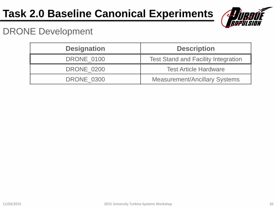
DRONE Development
Designation Description
DRONE_0100 Test Stand and Facility Integration
DRONE_0200 Test Article Hardware
DRONE_0300 Measurement/Ancillary Systems
Task 2.0 Baseline Canonical Experiments

11/03/2015 212015 University Turbine Systems Workshop
DRONE Development
Task 2.0 Baseline Canonical Experiments

11/03/2015 222015 University Turbine Systems Workshop
DRONE Development
Task 2.0 Baseline Canonical Experiments
11/03/2015 232015 University Turbine Systems Workshop
Task 2.0 Baseline Canonical Experiments
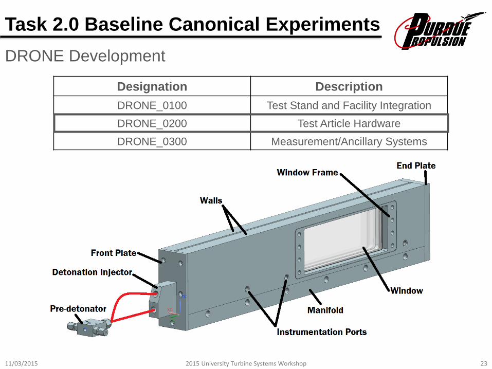
DRONE Development
Designation Description
DRONE_0100 Test Stand and Facility Integration
DRONE_0200 Test Article Hardware
DRONE_0300 Measurement/Ancillary Systems

11/03/2015 242015 University Turbine Systems Workshop
Task 2.0 Baseline Canonical Experiments
Design Conditions
● Propellants
o Fuel: gaseous methane
o Oxidizer: gaseous methane (with potential diluent)
● Initial Conditions
o P = 1 atm
o T = 298K
● Detonation Properties (CH4-GOx)
o (Cell Size) = 2.5 mm
o uCJ = 2390 m/s

11/03/2015 252015 University Turbine Systems Workshop
Task 2.0 Baseline Canonical Experiments
Design Conditions
● Flow Rates
o Fuel: 0.1288 lbm/s
o Oxidizer: 0.5152 lbm/s
● Manifold Pressure Ratios
o Fuel: 2.7
o Oxidizer: 1.8
● Starting conditions chosen for high confidence level
● Modularity optically-accessible test article hardware and ancillary components
11/03/2015 262015 University Turbine Systems Workshop
Task 2.0 Baseline Canonical Experiments
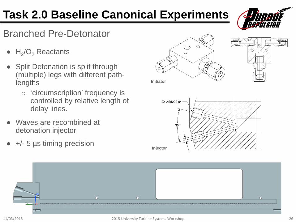
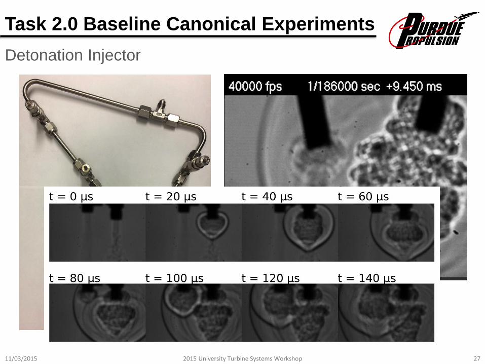
Branched Pre-Detonator
● H2/O2 Reactants
● Split Detonation is split through (multiple) legs with different path-lengths
o ‘circumscription’ frequency is controlled by relative length of delay lines.
● Waves are recombined at detonation injector
● +/- 5 µs timing precision
Initiator
Injector
11/03/2015 272015 University Turbine Systems Workshop
Task 2.0 Baseline Canonical Experiments
Detonation Injector

11/03/2015 282015 University Turbine Systems Workshop
Task 2.0 Baseline Canonical Experiments
Detonation Injector

11/03/2015 292015 University Turbine Systems Workshop
Task 2.0 Baseline Canonical Experiments
Detonation Injector

11/03/2015 302015 University Turbine Systems Workshop
Task 2.0 Baseline Canonical Experiments
Detonation Injector
11/03/2015 312015 University Turbine Systems Workshop
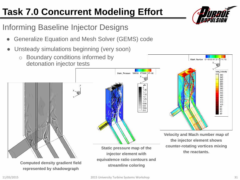
Detailed CAD Walk-Through: Injector
Velocity and Mach number map of
the injector element shows
counter-rotating vortices mixing
the reactants.Static pressure map of the
injector element with
equivalence ratio contours and
streamline coloringComputed density gradient field
represented by shadowgraph
Task 7.0 Concurrent Modeling Effort
Informing Baseline Injector Designs
● Unsteady simulations beginning (very soon)
o Boundary conditions informed by detonation injector tests
● Generalize Equation and Mesh Solver (GEMS) code

11/03/2015 322015 University Turbine Systems Workshop
Looking Forward
TaskTime
Required
Estimated
Completion
Detailed Design of DRONE_0200 Test Article 12 weeks 11/20/2015
Demonstration of Branched Initiation 8 weeks Complete
Test Article Fabrication 10 weeks January
Detailed Design of DRONE_0300 Ancillary Systems 4 weeks December
Ancillary System Fabrication 4 weeks January
Facility Integration 4 weeks 03/01/2016
Validation of System Operations
Pressure Checks, Leak Checks, etc.2 weeks 03/15/2016
Baseline Reacting Tests
Verify Safe, Repeatable Operation
Data Reduction Code Development
2 weeks 04/01/2016
Initiation of Advanced Optical Measurements - -
Fall 2015 – Spring 2016 Project Schedule
11/03/2015 332015 University Turbine Systems Workshop
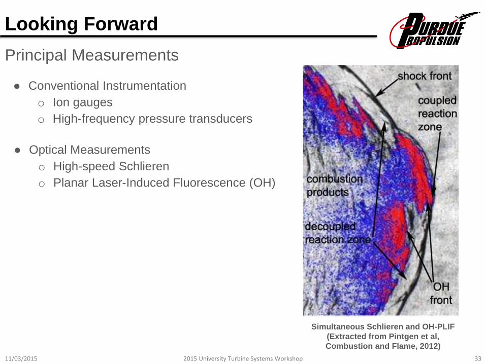
Simultaneous Schlieren and OH-PLIF
(Extracted from Pintgen et al,
Combustion and Flame, 2012)
● Conventional Instrumentation
o Ion gauges
o High-frequency pressure transducers
● Optical Measurements
o High-speed Schlieren
o Planar Laser-Induced Fluorescence (OH)
Principal Measurements
Looking Forward

11/03/2015 342015 University Turbine Systems Workshop
Looking Farther Forward
Task Breakdown
1) Project Management and Planning
2) Baseline Canonical Experiments
3) Subscale Combustor Facility Development
4) Integral Measurement of Pressure Gain
5) Detailed Measurements of Exit Conditions
6) Emissions Measurements
7) Computational Model Development
‘Unwrapped’ RDE test article
design is at CDR-level (left) with
complementary simulation
informing baseline injector design
(above)
11/03/2015 352015 University Turbine Systems Workshop
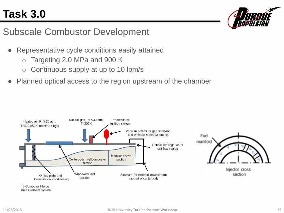
Task 3.0
Subscale Combustor Development
● Representative cycle conditions easily attained
o Targeting 2.0 MPa and 900 K
o Continuous supply at up to 10 lbm/s
● Planned optical access to the region upstream of the chamber
11/03/2015 362015 University Turbine Systems Workshop
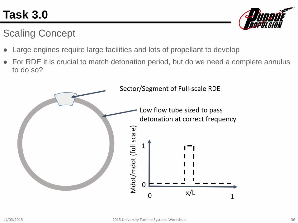
● Large engines require large facilities and lots of propellant to develop
● For RDE it is crucial to match detonation period, but do we need a complete annulus to do so?
Sector/Segment of Full-scale RDE
Low flow tube sized to pass detonation at correct frequency
Md
ot/
md
ot
(fu
ll sc
ale)
x/L
1
1
0
0
Task 3.0
Scaling Concept
11/03/2015 372015 University Turbine Systems Workshop
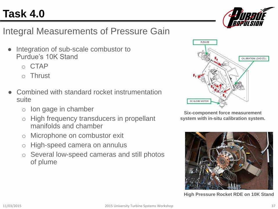
Six-component force measurement
system with in-situ calibration system.
Task 4.0
Integral Measurements of Pressure Gain
● Integration of sub-scale combustor to Purdue’s 10K Stand
o CTAP
o Thrust
● Combined with standard rocket instrumentation suite
o Ion gage in chamber
o High frequency transducers in propellant manifolds and chamber
o Microphone on combustor exit
o High-speed camera on annulus
o Several low-speed cameras and still photos of plume
High Pressure Rocket RDE on 10K Stand
11/03/2015 382015 University Turbine Systems Workshop
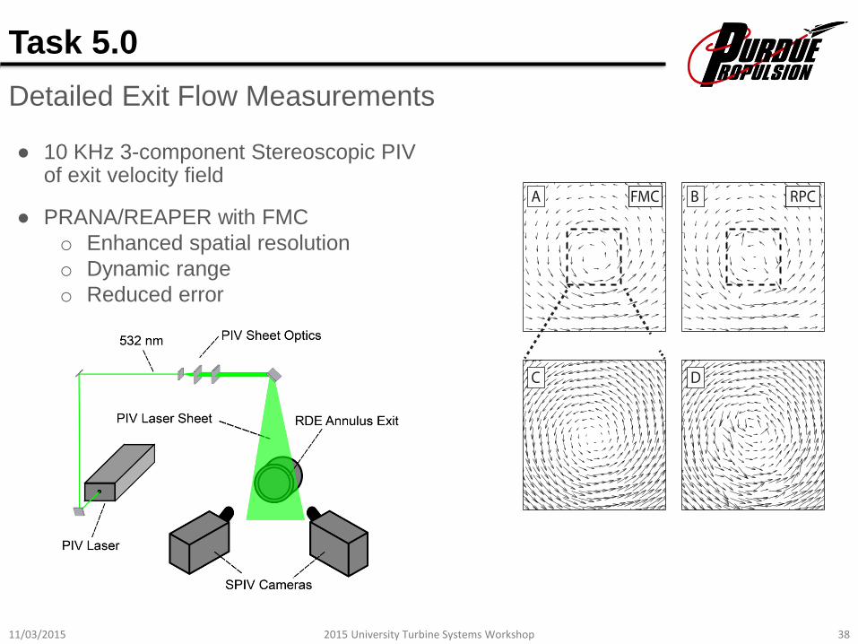
● 10 KHz 3-component Stereoscopic PIV of exit velocity field
Task 5.0
Detailed Exit Flow Measurements
● PRANA/REAPER with FMC
o Enhanced spatial resolution
o Dynamic range
o Reduced error
11/03/2015 392015 University Turbine Systems Workshop
● Water-cooled sampling probe
o Hydraulic average with choked inlet holes
o Quenched kinetics from sampling and probe cooling
● Sample gas drawn into purged vessel for analysis after completion of transient test operations
● Flame Ionization Detector (FID) measures unburned hydrocarbon concentration
● FTIR spectrometer measures NO, NO2, CO, CO2, H2O concentration
● Separate detector for O2 concentration
Task 6.0
Emissions Characterization

11/03/2015 402015 University Turbine Systems Workshop
Summary
Progress and Current Outlook
● Progress is underway on DRONE development
o Canonical platform to perform advanced measurements of key processes
o Informing complementary numerical modeling effort
● Branched initiation device has been demonstrated
o Tunable channel forcing with high precision
o Pulses remain coupled into channel
● Concurrent efforts with high pressure rocket RDE are developing experience base for Tasks 3.0-6.0 in Years 2 and 3.
