advances in element technology: solid-shell element · pdf fileadvances in element technology:...
TRANSCRIPT

Advances in Element Technology: Solid-Shell Element
Wenjie XieANSYS, Inc

NAFEMS 2020 Vision of Engineering Analysis and Simulation
Outline
• Motivation• Formulations• Composite application• Future development

NAFEMS 2020 Vision of Engineering Analysis and Simulation
Limitations in shell elements
• Nonlinear MPCs or transitional elements are required for connecting shell and solid elements
• Difficulties in the specialization of general three-dimensional material laws to plane-stress state.
• Definition of contact interaction needs special attention
• Treatment of variable thickness is unclear
In the above areas, use of continuum elements would be more desirable.
NAFEMS 2020 Vision of Engineering Analysis and Simulation
Locking in linear solid elements
• The error in the kinematic approximation with linear solid elements becomes apparent in bending dominant problems
• This error is magnified as the thickness to span ratio decreases, which beyond a certain ratio may make the FE model excessively stiff locking
• Current element technologies, such as the enhanced strains, are shown not sufficient to remedy this numerical locking in linear solid elements
NAFEMS 2020 Vision of Engineering Analysis and Simulation
Design of a Solid-Shell (SOLSH190)
• Involves only displacement nodal DOFs and features an eight-node brick connectivity. Thus the transition problem between solid and shell elements can be eliminated.
• Performs well in simulating shell structures with a wide range of thickness (from extremely thin to moderate thick).
• Is compatible with 3D constitutive models and automatically accounts for thickness change.
• Performs well for both flat-plate and curved shells.
NAFEMS 2020 Vision of Engineering Analysis and Simulation
Issues to address
• Transverse shear locking that originates from spurious shear stresses in plate bending cases
• Thickness locking due to the spurious thickness normal stress in plate bending cases
• Curvature locking that stems from the incompatible thickness normal strain when the element is skewed in thickness direction
• Membrane locking induced by the spurious in-plane stresses in the in-plane bending cases
NAFEMS 2020 Vision of Engineering Analysis and Simulation
Issues to address (cont.)
• Numerical ill-conditioning due to large ratio between transverse and in-plane stiffness
• Mesh distortion• Geometrical nonlinearity, including finite
transverse shear deformation• Material nonlinearity that also accounts for
nonlinear transverse shear constitutive relations
All above issues must be properly handled to produce a truly locking-free Solid-Shell in both linear and nonlinear analyses
NAFEMS 2020 Vision of Engineering Analysis and Simulation
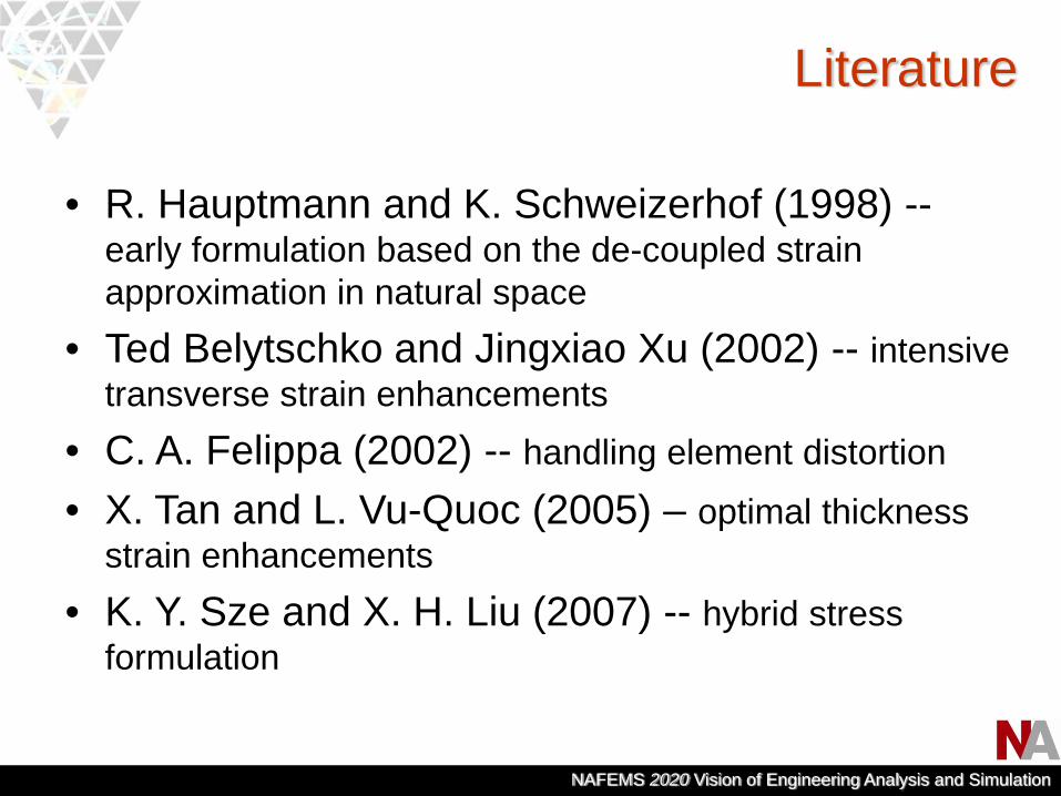
Literature
• R. Hauptmann and K. Schweizerhof (1998) --early formulation based on the de-coupled strain approximation in natural space
• Ted Belytschko and Jingxiao Xu (2002) -- intensive transverse strain enhancements
• C. A. Felippa (2002) -- handling element distortion
• X. Tan and L. Vu-Quoc (2005) – optimal thickness strain enhancements
• K. Y. Sze and X. H. Liu (2007) -- hybrid stress formulation

NAFEMS 2020 Vision of Engineering Analysis and Simulation
Basic SOLSH190 approaches
• Establish kinematic relations for in-plane and normal directions separately with different methods. – The in-plane strain components are evaluated with the
standard tri-linear shape functions, while the thickness-related components are obtained based on the assumed natural strains.
• Employ de-coupled strain enhancements to further improve the element performance in both out-of-plane and in-plane bending dominant situations.

NAFEMS 2020 Vision of Engineering Analysis and Simulation
Solid-Shell Bases
1
8
6
4 7
53
2
R1
R2
R3
X1
X2X3
X1, X2, and X3: bases for the global Cartesian system. Corresponding coordinates: x1, x2, and x3.
R1, R2, and R3: bases for element natural system. Corresponding coordinates: r1, r2, r3.
⎭⎬⎫
⎩⎨⎧
∂∂
∂∂
∂∂
=
⎭⎬⎫
⎩⎨⎧
∂∂
∂∂
∂∂
=
⎭⎬⎫
⎩⎨⎧
∂∂
∂∂
∂∂
=
3
3
3
2
3
13
2
3
2
2
2
12
1
3
1
2
1
11
,,
,,
,,
rx
rx
rxR
rx
rx
rxR
rx
rx
rxR

NAFEMS 2020 Vision of Engineering Analysis and Simulation
Evaluation of Natural Strains
Where , , are eight tri-linear shape functions, and
are eight nodal displacement vectors referred in global Cartesian system.
( )
( )
( ) ( )∑∑
∑
∑
==
=
=
⋅∂∂
+⋅∂∂
=
⋅∂∂
=
⋅∂∂
=
8
11
2
8
12
112
8
12
222
8
11
111
i
ii
i
ii
i
ii
i
ii
RUrNRU
rN
RUrN
RUrN
ε
ε
ε
• In-plane components: , and 11ε 22ε 12ε
iN 8,...,1=i{ }iiii uuuU 321 ,,=
NAFEMS 2020 Vision of Engineering Analysis and Simulation
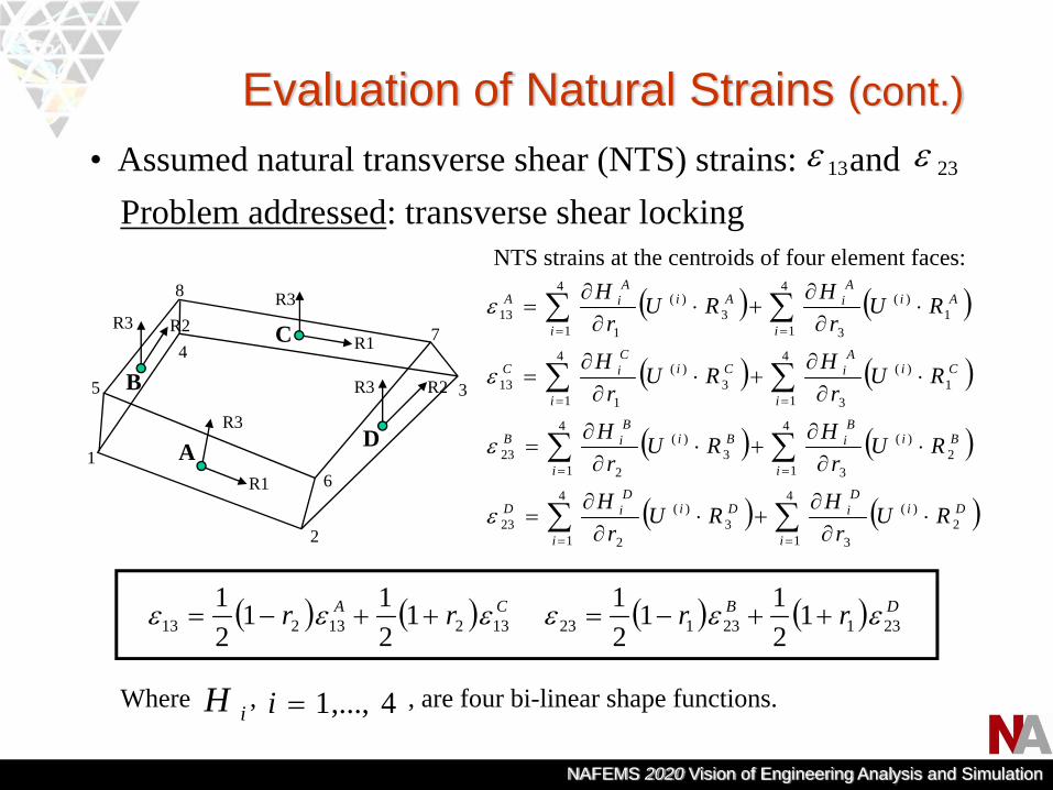
Evaluation of Natural Strains (cont.)
Where , , are four bi-linear shape functions.
• Assumed natural transverse shear (NTS) strains: and 13ε 23ε
iH 4,...,1=i
R1
R3
1
8
6
47
5 3
2
A
R3
R1C
R3 R2
D
B
R3 R2
( ) ( ) CA rr 13213213 1211
21 εεε ++−= ( ) ( ) DB rr 23123123 1
211
21 εεε ++−=
NTS strains at the centroids of four element faces:
( ) ( )
( ) ( )
( ) ( )
( ) ( )∑∑
∑∑
∑∑
∑∑
==
==
==
==
⋅∂∂
+⋅∂∂
=
⋅∂∂
+⋅∂∂
=
⋅∂∂
+⋅∂∂
=
⋅∂∂
+⋅∂∂
=
4
12
)(
3
4
13
)(
223
4
12
)(
3
4
13
)(
223
4
11
)(
3
4
13
)(
113
4
11
)(
3
4
13
)(
113
i
DiDi
i
DiDiD
i
BiBi
i
BiBiB
i
CiA
i
i
CiCiC
i
AiA
i
i
AiA
iA
RUr
HRUr
H
RUr
HRUr
H
RUr
HRUr
H
RUr
HRUr
H
ε
ε
ε
ε
Problem addressed: transverse shear locking
NAFEMS 2020 Vision of Engineering Analysis and Simulation
Other SOLSH190 element technologies
• A similar assumed strain approach is taken for formulating the thickness natural stains.Problem addressed: curvature locking
• De-coupled strain enhancements are applied separately to in-plane and thickness strain components.Problem addressed: membrane and thickness locking
• Transverse normal and shear stiffness are reduced when thickness becomes extremely small. This scaling is justified since in this case transverse strain energy is insignificant.Problem addressed: numerical ill-conditioning

NAFEMS 2020 Vision of Engineering Analysis and Simulation
Not discussed:• Nonlinear extension to account for both material and
geometrical nonlinearities• Handling of distorted geometry
Scaled(numerical ill-conditioning)
23ε 13ε
Assumed(transverse shear locking
thickness locking, curvature locking)
33ε11ε 22ε 12ε
Enhanced(membrane locking,thickness locking)
Summary of SOLSH190 Formulations
NAFEMS 2020 Vision of Engineering Analysis and Simulation
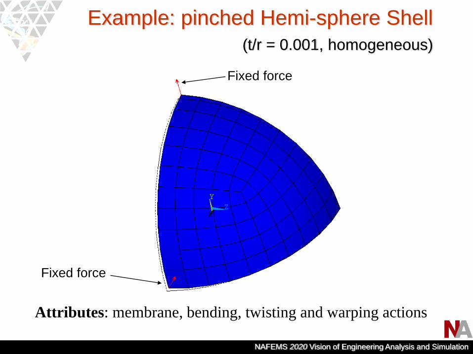
Example: pinched Hemi-sphere Shell(t/r = 0.001, homogeneous)
Attributes: membrane, bending, twisting and warping actions
Fixed force
Fixed force

NAFEMS 2020 Vision of Engineering Analysis and Simulation
Solution convergence wrt mesh refinement
-0.1
0.1
0.3
0.5
0.7
0.9
1.1
1 6 11 16 21 26
# Elements Per Edge
Max
. Rad
ial D
ispl
.
ANSYS SHELL
ANSYS SOLID
SOLIDSHELL

NAFEMS 2020 Vision of Engineering Analysis and Simulation
Example: automobile exterior panel
Mid-surface extraction based shell meshing may not be practical for parts with complex geometry and variable thicknesses, or when design parameters still need constant modification.
Predicted deformation with SOLSH190 model. The same model with regular linear solid elements produces one fifth of the expected deformation, showing clear sign of locking.
Pressure

NAFEMS 2020 Vision of Engineering Analysis and Simulation
Example: composite stiffened panel
Stringer Flange
Stringer Web
Skin
• Difficulties in shell modeling:– Need to consider offsets and specify top/bottom contact
faces in the contact set-up between the flange and skin – The web and flange connection needs special attention

NAFEMS 2020 Vision of Engineering Analysis and Simulation
Example: composite stiffened panel
Bonded contact
Standard contactF
F = 30 KN
F = 45 KN F = 135 KN
NAFEMS 2020 Vision of Engineering Analysis and Simulation
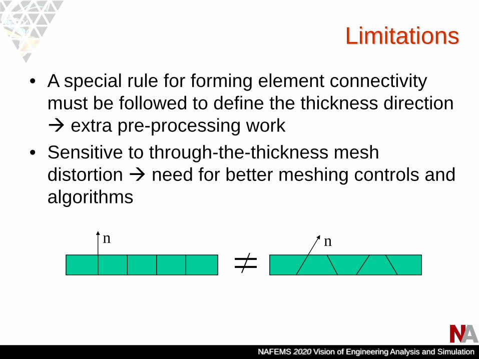
Limitations
• A special rule for forming element connectivity must be followed to define the thickness direction
extra pre-processing work• Sensitive to through-the-thickness mesh
distortion need for better meshing controls and algorithms
n n

NAFEMS 2020 Vision of Engineering Analysis and Simulation
Application to Laminated composites
• Layered composites commonly have low transverse stiffness. Finite and highly non-uniform transverse deformation can occur.
• Locking and other numerical irregularities may occur in thin composite models.
• Material and damage modeling are often based on the full 3D stress states.With the locking-free properties and solid element connectivity, SOLSH190 is desirable in layered composite simulations.

NAFEMS 2020 Vision of Engineering Analysis and Simulation
Predication of Interlaminar stresses
• SOLSH190 only has linear displacement field through-the-thickness limited accuracy in transverse strains.
• The shear adjustment technique cannot be applied due to the difficulty in determining the top/bottom traction conditions.
• Generally, use of more elements in the thickness direction (or stacking) is required to obtain accurate interlaminar stress distributions.
NAFEMS 2020 Vision of Engineering Analysis and Simulation
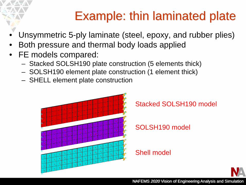
• Unsymmetric 5-ply laminate (steel, epoxy, and rubber plies)• Both pressure and thermal body loads applied• FE models compared:
– Stacked SOLSH190 plate construction (5 elements thick)– SOLSH190 element plate construction (1 element thick)– SHELL element plate construction
Shell model
SOLSH190 model
Stacked SOLSH190 model
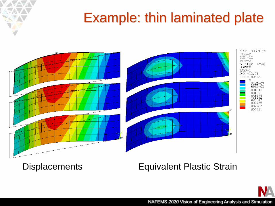
Example: thin laminated plate
NAFEMS 2020 Vision of Engineering Analysis and Simulation
Equivalent Plastic Strain
Example: thin laminated plate
Displacements

NAFEMS 2020 Vision of Engineering Analysis and Simulation
• Interlaminar shear stresses (SXZ,SYZ) are dependent on laminate construction:– For the SOLSH190 model
consisting of one element through the thickness, the details of the shear stress variation is lost.
– For the stacked SOLSH190 model consisting of five elements through the thickness, the variation is captured. However, more elements are still needed for a smoother stress distribution.
SXZ
SYZ
SXZ
SYZ
Example: thin laminated plate
NAFEMS 2020 Vision of Engineering Analysis and Simulation
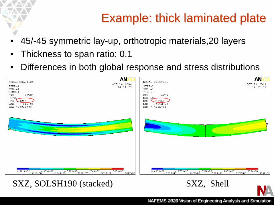
• 45/-45 symmetric lay-up, orthotropic materials,20 layers• Thickness to span ratio: 0.1• Differences in both global response and stress distributions
Example: thick laminated plate
SXZ, SOLSH190 (stacked) SXZ, Shell
NAFEMS 2020 Vision of Engineering Analysis and Simulation
Future of Solid-Shell element• Element formulations
– Higher order transverse strain formulation with or without layer-wise displacement fields, to improve the accuracy in transverse strains. Suitable for modeling the laminate with single element
– Hybrid stress formulation that incorporates transverse stresses as independent variables, to ensure the interlaminar transverse stress continuity. Suitable for the stacking option (i.e., one element per layer)
– Special element shape correction technique for improving robustness and solution consistency in the distorted mesh
NAFEMS 2020 Vision of Engineering Analysis and Simulation
Future of Solid-Shell (cont.)
• Multi-physics – Thermal, mechanical, and electric potential coupled
field solid-shell for modeling smart and piezoelectric structures
• Pre-processing– Thin solid meshing algorithm to minimize mesh
distortion through the thickness– layered composite meshing to create refined mesh in
the thickness direction based on the lay-up information• Membrane option
– To eliminate numerical ill-conditioning and improve efficiency in extremely thin structure
NAFEMS 2020 Vision of Engineering Analysis and Simulation
Conclusion
• With its locking-free property, solid element connectivity, and 3D strain state compatibility, Solid-Shell may represent the future trend in the modeling of shell and laminated composite structures.
• Solid-Shell based simulation can be further enhanced in areas such as meshing, element formulation, and multi-physics capability.