advancements made to the wingman software-in-the … · training of warfighter teaming within...
TRANSCRIPT

ARL-TR-8254 ● DEC 2017
US Army Research Laboratory
Advancements Made to the Wingman Software-in-the-Loop (SIL) Simulation: How to Operate the SIL by Kristin E Schaefer, Ralph W Brewer, E Ray Pursel, Anthony Zimmermann, and Eduardo Cerame
Approved for public release; distribution is unlimited.

NOTICES
Disclaimers
The findings in this report are not to be construed as an official Department of the Army position unless so designated by other authorized documents.
Citation of manufacturer’s or trade names does not constitute an official endorsement or approval of the use thereof.
Destroy this report when it is no longer needed. Do not return it to the originator.

ARL-TR-8254 ● DEC 2017
US Army Research Laboratory
Advancements Made to the Wingman Software-in-the-Loop (SIL) Simulation: How to Operate the SIL by Kristin E Schaefer Human Research and Engineering Directorate, ARL Ralph W Brewer Vehicle Technology Directorate, ARL E Ray Pursel Naval Surface Warfare Center Dahlgren Division Anthony Zimmermann DCS Corporation Alexandria, VA Eduardo Cerame Tank Automotive Research, Development and Engineering Center
Approved for public release; distribution is unlimited.

ii
REPORT DOCUMENTATION PAGE Form Approved OMB No. 0704-0188
Public reporting burden for this collection of information is estimated to average 1 hour per response, including the time for reviewing instructions, searching existing data sources, gathering and maintaining the data needed, and completing and reviewing the collection information. Send comments regarding this burden estimate or any other aspect of this collection of information, including suggestions for reducing the burden, to Department of Defense, Washington Headquarters Services, Directorate for Information Operations and Reports (0704-0188), 1215 Jefferson Davis Highway, Suite 1204, Arlington, VA 22202-4302. Respondents should be aware that notwithstanding any other provision of law, no person shall be subject to any penalty for failing to comply with a collection of information if it does not display a currently valid OMB control number. PLEASE DO NOT RETURN YOUR FORM TO THE ABOVE ADDRESS.
1. REPORT DATE (DD-MM-YYYY)
December 2017 2. REPORT TYPE
Technical Report 3. DATES COVERED (From - To)
April 2017–December 2017 4. TITLE AND SUBTITLE
Advancements Made to the Wingman Software-in-the-Loop (SIL) Simulation: How to Operate the SIL
5a. CONTRACT NUMBER
5b. GRANT NUMBER
5c. PROGRAM ELEMENT NUMBER
6. AUTHOR(S)
Kristin E Schaefer, Ralph W Brewer, E Ray Pursel, Anthony Zimmermann, and Eduardo Cerame
5d. PROJECT NUMBER
5e. TASK NUMBER
5f. WORK UNIT NUMBER
7. PERFORMING ORGANIZATION NAME(S) AND ADDRESS(ES)
US Army Research Laboratory, RDRL HRF D APG MD 21005 Naval Surface Warfare Center Dahlgren Division, CO, NSWCDD H33 Dahlgren VA 22448 DCS Corp., 6909 Metro Park Dr. #500 Alexandria, VA 22310 US Army TARDEC, RDTA RTI GVR Warren MI 48397
8. PERFORMING ORGANIZATION REPORT NUMBER
ARL-TR-8254
9. SPONSORING/MONITORING AGENCY NAME(S) AND ADDRESS(ES)
US Army Research Laboratory US Army Tank Automotive Research, Development and Engineering Center
10. SPONSOR/MONITOR'S ACRONYM(S)
11. SPONSOR/MONITOR'S REPORT NUMBER(S)
TARDEC 12. DISTRIBUTION/AVAILABILITY STATEMENT
Approved for public release; distribution is unlimited. 13. SUPPLEMENTARY NOTES 14. ABSTRACT
This report supports the advanced development of the US Army Robotic Wingman’s Joint Capabilities Technology Demonstration software-in-the-loop (SIL) simulation testbed. It is a collaboration including the US Army Research Laboratory, US Army Tank Automotive Research, Development and Engineering Center, and Naval Surface Warfare Center Dahlgren Division. The purpose is to provide advanced software development, rapid prototyping, and early assessment and training of Warfighter teaming within manned–unmanned gunnery operations. This report reviews the January 2017 integration event (documented in ARL-TN-0830) highlighting the setup and capabilities of the SIL, and describes advancements to the SIL (including creation of virtual environments that matched real-world gunnery test courses) and increased compatibility of the SIL software and simulation systems. It also provides a “how-to” guide for setting up the SIL and documentation for how to assess and correct for potential errors across the SIL.
15. SUBJECT TERMS
fire control, manned–unmanned teaming, autonomy, simulation, Wingman
16. SECURITY CLASSIFICATION OF: 17. LIMITATION OF ABSTRACT
UU
18. NUMBER OF PAGES
54
19a. NAME OF RESPONSIBLE PERSON
Kristin E Schaefer a. REPORT
Unclassified b. ABSTRACT
Unclassified
c. THIS PAGE
Unclassified
19b. TELEPHONE NUMBER (Include area code)
410-278-5972 Standard Form 298 (Rev. 8/98)
Prescribed by ANSI Std. Z39.18

Approved for public release; distribution is unlimited. iii
Contents
List of Figures v
1. Introduction and Summary 1
2. Wingman Program Overview 1
3. Wingman SIL Design and Goals 2
3.1 Software Integration 2
3.2 SIL Design vs. Real World 3
4. Integrating Real-World Test Courses as Virtual Environments 4
4.1 Integration of Geospatial Data into Unity3d 4
4.2 Matching Terrains in ANVEL and Unity3d 4
5. How-To Guidelines to Set up the SIL 5
5.1 Equipment 5
5.1.1 Vehicle Mobility 5
5.1.2 ARES 6
5.1.3 Unity 6
5.1.4 WMI 7
5.1.5 Setup for Integration in a “Humvee” 7
5.2 Setup and Integration 7
6. Addressing Potential Software-Integration Errors 8
6.1 General Instructions 9
6.2 ANVEL 9
6.2 RTK 10
6.3 ARES 12
6.3 Unity3d 12
6.4 WMI 13
7. Conclusion and Next Steps 14

Approved for public release; distribution is unlimited. iv
8. References 16
Appendix A. Instructions for Geospatial Terrain Data in Unity3d 17
Appendix B. Instructions for Modifying Terrain Data in Blender 29
Appendix C. Software-in-the-Loop (SIL) Setup Instructions 37
List of Symbols, Abbreviations, and Acronyms 43
Distribution List 45

Approved for public release; distribution is unlimited. v
List of Figures
Fig. 1 Wingman SIL’s detailed software connections .................................... 3
Fig. 2 SIL configuration .................................................................................. 8
Fig. 3 List of potential errors within ANVEL and RTK ................................. 9
Fig. 4 Loading correct vehicle camera view in ANVEL ............................... 10
Fig. 5 Cost map screen loaded from RTK ..................................................... 11
Fig. 6 Example of output connecting RTK to ANVEL................................. 11
Fig. 7 Example of output with a bad connection between ANVEL and RTK............................................................................................................. 12
Fig. 8 Multiple WMI setup with Commander Display (left), Robotic Vehicle Gunner setup (center), and Robotic Vehicle Operator setup (right) ... 13
Fig. A-1 Google Earth with place markers ........................................................ 19
Fig. A-2 EarthExplorer home page ................................................................... 20
Fig. A-3 EarthExplorer Data Sets page example............................................... 21
Fig. A-4 EarthExplorer Results page example .................................................. 22
Fig. A-5 New default terrain ............................................................................. 24
Fig. A-6 Import Heightmap dialog .................................................................... 25
Fig. A-7 Add Texture dialog ............................................................................. 26
Fig. A-8 The resulting terrain ............................................................................ 27
Fig. B-1 Blender menu for importing .obj file .................................................. 30
Fig. B-2 Blender menu for UV/Image Editor panel .......................................... 31
Fig. B-3 Blender menu selection for UV projection from view........................ 32
Fig. B-4 Blender menu button to import image for UV map ............................ 32
Fig. B-5 Before and after scaling UV map to image ......................................... 33
Fig. B-6 ANVEL menu for converting to VPM file ......................................... 34
Fig. B-7 ANVEL menu for converting to OGRE mesh file .............................. 34
Fig. C-1 Unity start screen ................................................................................ 40

Approved for public release; distribution is unlimited. vi
INTENTIONALLY LEFT BLANK.

Approved for public release; distribution is unlimited. 1
1. Introduction and Summary
The US Army Research Laboratory (ARL), US Army Tank Automotive Research Development and Engineering Center (TARDEC), DCS Corp., and Naval Surface Warfare Center Dahlgren Division (NSWCDD) worked together to advance the capabilities of a software-in-the-loop (SIL) simulation environment in support of the larger TARDEC–Wingman Joint Capabilities Technology Demonstration (JCTD). The Wingman program began in fiscal year 2014 to provide robotic technological advances and experimentation to increase the autonomous capabilities of manned and unmanned combat-support vehicles. A major goal of this program as a whole is to advance manned–unmanned teaming initiatives by iteratively defining and decreasing the gap between autonomous vehicle control and required level of human interaction. Outcomes of these joint research efforts for development of this SIL support the design of a robotic system user interface and enhance communication among manned–unmanned team members, which are critical to achieve Training and Doctrine Command 6+1-required capabilities for robotics and autonomous systems.
This report describes the SIL, technical advances to integrate real-world environments within a virtual environment, how-to guidelines for setting up the SIL, and documentation for assessing and correcting integration issues. The setup and capabilities of the SIL provide advanced software development, rapid prototyping, and early assessment and training of Warfighter teaming within manned–unmanned gunnery operations (Schaefer et al. 2017). More specifically, real-world gunnery test courses were designed and integrated into the virtual environment in order to support a smooth transition from simulation to the real world. In addition, specific goals and technical challenges are discussed throughout. Specific guidelines for setting up and correcting potential errors or technical issues are included.
2. Wingman Program Overview
The Army’s Robotic Wingman program currently has a single manned M1151 High Mobility Multipurpose Wheeled Vehicle (HMMWV) working with a single unmanned robotic M1097 HMMWV operating in a joint gunnery task. The manned-vehicle crew comprises a driver, commander, gunner (also responsible for target detection and lasing for the unmanned vehicle), robot-vehicle operator to monitor or control mobility, and robot-vehicle gunner to monitor and assist with target acquisition and firing. Currently, the project’s main goal is to attain direct-fire weapon proficiency by delivering fire on target(s) and qualifying under the

Approved for public release; distribution is unlimited. 2
Table VI qualification guidelines on gunnery-target ranges as described in the US Army Training and Doctrine Command’s Training Circular 3-20.31 (TRADOC 2015). Future advancements from this program foresee the single manned vehicle working cooperatively with multiple unmanned vehicles supporting manned–unmanned teaming (MUM-T) initiatives in complex, uncertain environments.
3. Wingman SIL Design and Goals
The Wingman SIL was designed to use all of the same real-world vehicle software, with limited deviations in integration protocols, to create a means for successful software development, integration, and rapid prototype development. In addition, a second goal in the design of the SIL was for Warfighter-in-the-loop assessment and training to advance scientific understanding of future MUM-T operational needs, including but not limited to implications of design on performance, increasing shared situation awareness to support the Army “asymmetric vision” and “decide faster” initiatives, and calibrate appropriate trust in the unmanned weaponized vehicle.
3.1 Software Integration
The current software includes the Robotic Technology Kernel (RTK) for autonomous mobility, the Autonomous Remote Engagement System (ARES) supporting the autonomous targeting and weapons systems control, and the Wingman’s Warfighter Machine Interface (WMI) providing individualized, customized interactive displays for the Wingman commander, robot-vehicle driver, and robot-vehicle gunner. Figure 1 (adapted from Schaefer et al 2017) provides a visual depiction of the detailed software connections and required integration with 2 simulation systems: the Unity3d Game Engine and Quantum Signal’s Autonomous Navigation and Virtual Environment Laboratory (ANVEL).
ANVEL was developed as a simulation tool for studying robotic assets in various environments with a variety of sensors. Integration with the RTK vehicle-mobility software was achieved using ANVEL’s plugin interface and supports rapid testing of current and potential mobility capabilities with minimal integration effort. The Unity3D Game Engine was integrated into the SIL because it provides a customizable, realistic virtual environment that supports complex interactions with terrain and dynamic events that stimulate the ARES sensors (e.g., camera and LRF data), actuates ARES output (e.g., weapon commands), and simulates physical effects such as wind effects and bullet fly-outs. All software, including video output from the simulation systems, is used to update information on the different WMI displays.

Approved for public release; distribution is unlimited. 3
The combination of simulation software allowed the SIL to utilize the strengths of each program without the need for developing additional capabilities. ANVEL’s main strength lies in its ability to accurately simulate the dynamics of the robotic vehicle and all of the robotic sensors in real time. Unity’s strength lies in its flexibility for adding elements and scenarios to a scene, its quality video rendering for target tracking and acquisition, and its ability to incorporate dynamic and customizable interactions with the virtual environment. ANVEL’s physics simulation would have required extensive modifications to add elements like weapon fire and the Unity simulation and would have required developing or integrating new systems to add the necessary robotic sensors and dynamics; hence, federation was the ideal approach. Figure 1 depicts the various software connections, including those to the RTK of the Robotic Operating System (ROS). The 2 Soldiers remotely controlling the unmanned vehicle’s operation and weapon are called “Mobility Operator” and “Robotic Gunner” (and later, “Robotic Vehicle Operator” and “Robotic Weapon Operator”).
Fig. 1 Wingman SIL’s detailed software connections
3.2 SIL Design vs. Real World
There were 2 main deviations in this early version of the SIL from the real-world setup. First, the virtual environment provides all of the sensor-data input rather than the real-world environment. The benefit of using a virtual environment is the capability to control for and modify the environment systematically in order to assess the software under different environmental constraints. However, it is also necessary to have the capability in the virtual environment to match the real-world test environments in order to validate the SIL, train Warfighters, and test the software-integration capabilities. Section 4 discusses the technical integration efforts and challenges associated with developing this capability. The second

Approved for public release; distribution is unlimited. 4
deviation was that the SIL does not require all 5 of the crew members to operate the system. At present, the key human-in-the-loop team members include the commander, robot vehicle operator, and robot vehicle gunner. For the current purposes of the SIL, the manned-vehicle driver and manned-vehicle gunner are simulated. The simulation environments support integration of these 2 roles at a later date.
4. Integrating Real-World Test Courses as Virtual Environments
In order to accurately test the Wingman system and transfer findings from simulation to the field, a goal of this SIL was to incorporate real-world Army gunnery training courses into the virtual environment. It was essential to integrate environmental features such as elevation, paths, objects, and obstacles as well as target locations and target types. Further, a number of technical challenges had to be overcome in order to have matching terrain databases in both ANVEL and Unity3d. Any divergence could directly impact the localization data required for the system to run effectively. This section of the report describes the process for matching real-world environments within the SIL.
4.1 Integration of Geospatial Data into Unity3d
Geospatial data for the desired area were found using the US Geological Survey’s EarthExplorer and were cropped, resized, and converted to a raw elevation data format using the Geospatial Data Abstraction Library (GDAL). Those raw elevation data were then imported into the Unity3d native terrain format. This provided the elevation requirements for the associated gunnery test range. In order to include ground-covering data, a matching satellite image of the area was also added to the Unity3d terrain by cropping the satellite image to the known extents (boundaries) of the terrain. Finally, vegetation and trees were added to the terrain by hand, using standard tools in the Unity3d editor to roughly match the satellite imagery. Appendix A has instructions for developing a terrain map for use by Unity3d.
4.2 Matching Terrains in ANVEL and Unity3d
A secondary technical challenge was to develop matching terrains in both ANVEL and Unity3d. This was a requirement since the localization data of the Wingman vehicle comes from ANVEL through the RTK to ARES. Accurate localization data are required since they directly support the gunnery controls within the Unity3d simulation as well as the camera feeds into the WMIs used by the commander,

Approved for public release; distribution is unlimited. 5
robot-vehicle operator, and robot-vehicle gunner. In order to address this technical challenge, terrain files were exported from Unity as an .obj file; imported into Blender, where they were rotated, translated, and given a terrain texture using a UV map to create a new .obj file; and, finally, converted in ANVEL from the edited .obj file to an Object-Oriented Graphics Rendering Engine (OGRE) mesh file that could be read by ANVEL as an environment. The Blender rotations and translation were needed to insure the physics mesh imported with the correct orientation and position into ANVEL. The UV map was needed to provide a texture on the terrain for confirming matching terrains between Unity and ANVEL. (Appendix B has instructions for the modification of terrain data in Blender.)
5. How-To Guidelines to Set up the SIL
This section discusses specific criteria needed to set up and use the SIL. Base equipment criteria, as well as setup and integration needs, are discussed.
5.1 Equipment
As depicted in Fig. 1, the current desktop Wingman SIL uses 3 desktop computers to run ANVEL and RTK, ARES, and Unity. It also uses 3 tablet computers for the WMI displays. In the future, an additional machine will be used as a LRAS3 operator station and will be a client to the Unity simulation and feed video and target position information to the Vehicle Commander’s WMI.
There are currently 3 SIL setups located at ARL, NSWCDD, and TARDEC. This allows for continued updates, advancement of software, and effective team collaboration. The following subsections provide some guidelines and recommendations for hardware requirements. It is important to note that the SIL can be run on multiple hardware varieties.*
5.1.1 Vehicle Mobility
The current instance of the SIL uses a single computer for both ANVEL and RTK through the use of a virtual machine (VM). ANVEL is run on the host Windows operating system, and an Ubuntu 14.04 VMware Player virtual machine is used for running RTK. The virtual machine uses a bridged network connection to share data among the host operating system (OS) and the VM as well as external computers.
* The SIL setup at ARL includes 3 Alienware Area 51 desktop computers with Microsoft Windows 8.1, Intel Core i7-5820K central processing unit at 3.30 GHz and 3301 Mhz, 6 core(s), 12 logical processor(s), 16-GB random-access memory (RAM), and NVIDIA GeForce GT980 graphics card for the ANVEL/RTK, ARES, and Unity3d machines. Either 3 Surface Pro 3 tablets running Windows 8 OS or 3 Surface Pro 4 tablets running Windows 10 OS are able to successfully operate the WMIs.

Approved for public release; distribution is unlimited. 6
As the VM uses a large portion of the RAM and processing cores of the computer, at least 8 GB of RAM and a Quad Core i7 processor are recommended. Some experimentation with the amount of memory and processor cores that should be assigned to the VM will be needed as the ideal amount will vary based on the specific hardware and software configuration of the computer. A graphics card is not required for either ANVEL or RTK, but can assist with ANVEL performance as light detection and ranging (LIDAR) devices can utilize a graphics card for improved performance. RTK normally uses 2 LIDARs for obstacle detection but with the VM setup this may need to be reduced to a single forward LIDAR to improve ANVEL performance.
While this setup is a frequent method of running RTK with ANVEL, a more ideal method would be to run ANVEL and RTK on separate machines running the required OS for all systems that are networked together. This avoids performance and networking problems that can arise from using a VM and generally simplifies the integration and software-update process.
5.1.2 ARES
ARES uses machine learning for detecting and tracking targets and implements those algorithms on graphics processing units. For this reason, ARES requires both a great deal of general-purpose processing as well as graphics-processing hardware. ARES is built upon ROS, which requires the machine’s operating system to be Ubuntu Linux. The ARES software has been demonstrated to run effectively in the SIL setup with an i7 Quad Core processor and 16-GB RAM. However, the preferred ARES hardware comprises two 12-core IBM Xeon processors, 128 GB of RAM, 2 NVIDIA Titan Black X video cards connected via NVIDIA’s Scalable Link Interface, and 4-gigabit Ethernet interfaces—matching the real-world system. The additional Ethernet interfaces will allow ARES to connect to the Picatinny Light Weight Remote Weapon Station, optics hardware, and Wingman networks as the SIL continues to be developed.
5.1.3 Unity
In order to stimulate ARES quickly enough to meet sensor-update requirements, Unity must be run on a machine with strong processing and graphics capabilities, though the OS can be either Microsoft Windows or Linux. A typical Unity machine is currently a seventh-generation IBM Core i7 Quad Core processor with 32-GB RAM, at least an NVIDIA GTX980 graphics processor, and at least one Ethernet interface.

Approved for public release; distribution is unlimited. 7
5.1.4 WMI
The preferred hardware specifications for the Wingman WMI are an Intel Core i7-6500U processor, 16-GB RAM, and 256-GB solid-state drive (SSD). The Wingman program is selecting new ruggedized tablets, which are likely to be Windows 10 multitouch enabled though subject to change. The Robotic Vehicle Operator typically has an Xbox controller, though most human interface device (HID)-compliant controllers are supported.
5.1.5 Setup for Integration in a “Humvee”
An eventual goal for the SIL is to package the simulation computers in a way that they can be placed in the trunk of the Command HMMWV and connected to the vehicle network and power supply. This would allow the JCTD team to run simulations using the real control stations rather than approximations. This would be valuable for assessing usability of the WMI in the space provided by the HMMWV, which will be noticeably different than the control stations currently used by the SIL. Some brief tests have been performed using an ANVEL station and have demonstrated that apart from form factor and computer power, integration work should be minimal.
5.2 Setup and Integration
Figure 2 depicts the layout for an experiment that sets the ARES, ANVEL, and Unity machines where only the investigator can see them. The WMI user stations are laid out in a similar fashion to where they would be sitting in the vehicle. There is also the possibility of putting each WMI station in a separate sound-proof room to focus on each station separately as opposed to the group setting.

Approved for public release; distribution is unlimited. 8
Fig. 2 SIL configuration
There is a process that needs to be followed for successful integration of multiple software systems with 2 simulation systems. The order of start-up events can directly affect the functionality of the system. While this process is still becoming streamlined, the current step-by-step guidelines are provided in Appendix C. These directions take into account that a user has all the approved and up-to-date software and has previously set up the software and ROS connections for the Wingman SIL. For example, the specific vehicle capabilities have already been added into an executable version of ANVEL. Similarly, the virtual environment and integration capabilities have already been built into an executable version of Unity3d. Specifics on how the RTK, ARES, and WMI interfaces work together through specific software solutions are also not discussed here. Only the order in which the developed applications are selected are provided in the step-by-step instructions.
6. Addressing Potential Software-Integration Errors
When setting up the SIL it is possible software-integration errors may occur. This section highlights some of these issues, what to look for to determine if an error did occur, and how to remedy the issue.

Approved for public release; distribution is unlimited. 9
6.1 General Instructions
Prior to launching any element of the SIL, it is important to test the network connectivity and settings of all components:
1) Firewall: All of the machines should have their firewalls turned off as this can prevent traffic from passing properly between machines. With the firewalls down, every computer should be able to communicate with every other computer, including the VM.
2) Check network compatibility: To test network capability open a terminal or command prompt window and type “ping” followed by each computer’s IP address. If you are unable to ping between any of the machines, double check that the network cables are seated properly, including adapters for the tablet computers, and that the IP addresses and subnets are correct. The Wingman SIL uses a 16-bit subnet mask.
6.2 ANVEL
In ANVEL, the best tool for debugging issues is the log window that opens in the lower left corner. Some errors are expected based on the models of the vehicles and sensors that are used for RTK. Figure 3 lists some of these possible errors. These errors will include messages indicating the meshes (e.g., terrain, vehicle, object, or sensor visual representations) being loaded are from older versions of OGRE, that a texture may be missing, or that a file could not be read properly. This log window will also be important for seeing details about environments and vehicles being loaded or other actions in ANVEL that are being executed.
Fig. 3 List of potential errors within ANVEL and RTK

Approved for public release; distribution is unlimited. 10
When starting ANVEL, the default viewpoint may not be positioned with the simulated vehicle in view; the camera may not be positioned where the vehicle is visible. To easily find the vehicle, select one of the MRZR all-terrain vehicle’s camera views from the drop-down menu in the upper left corner of the screen (see Fig. 4). These options will lock the camera to the vehicle. To allow for free camera movement again, click the button to the right of the camera-view drop-down menu.
Fig. 4 Loading correct vehicle camera view in ANVEL
Another potential issue that vehicle camera views are not showing up in the menu. Check the log menu for the specific message: Creating Vehicle from file PolarisMRZR4_withVelodyneHDL32E.master.vehicle.xml. If that message is not present, then there was an issue with loading the vehicle model. This could be due to an issue with the vehicle definition file or the VaneSimInit.xml file.
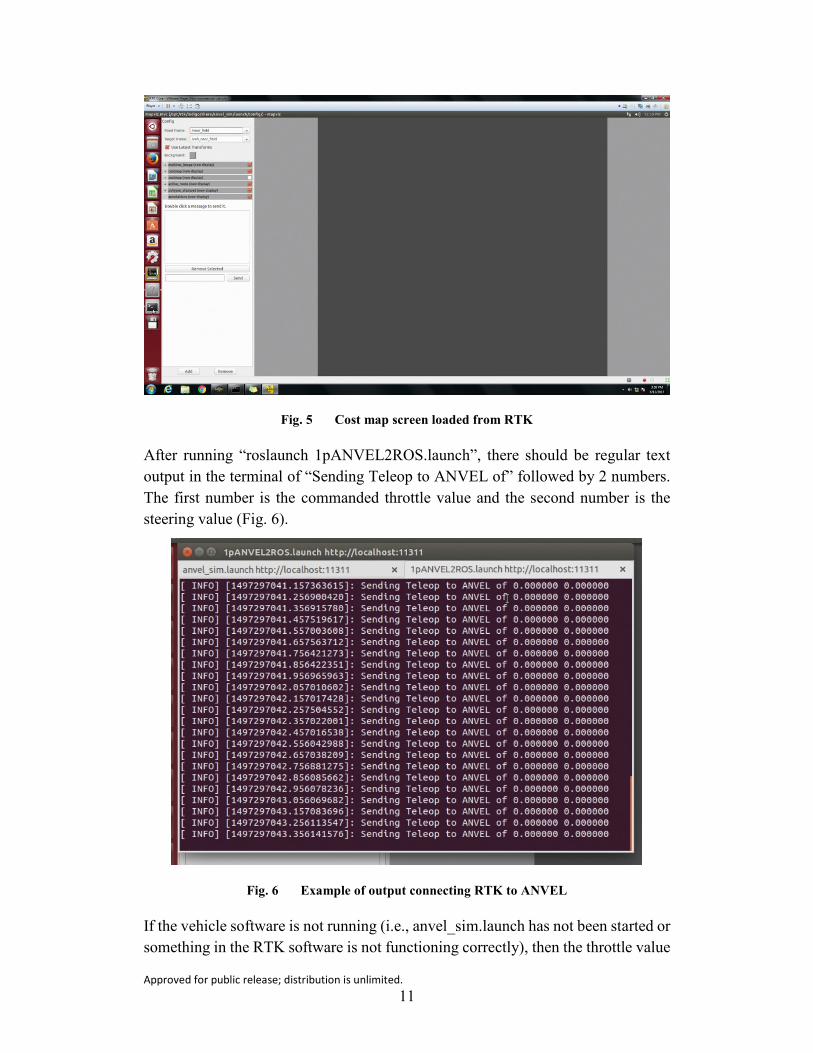
6.2 RTK
There are 2 main sections to look at to insure everything is running correctly with the RTK. First, when running the command “roslaunch anvel_sim.launch”, there should eventually be a cost map screen loaded in a window labeled mapviz.mvc (see Fig. 5). If the “roslaunch 1pANVEL2ROS.launch” command has not been executed or the ANVEL simulation has not been started, this cost map should be blank. If both ANVEL and ANVEL2ROS are running and the cost map is still blank, then something is not connecting correctly between the systems or there are no Velodyne data being generated in ANVEL.
Approved for public release; distribution is unlimited. 11
Fig. 5 Cost map screen loaded from RTK
After running “roslaunch 1pANVEL2ROS.launch”, there should be regular text output in the terminal of “Sending Teleop to ANVEL of” followed by 2 numbers. The first number is the commanded throttle value and the second number is the steering value (Fig. 6).
Fig. 6 Example of output connecting RTK to ANVEL
If the vehicle software is not running (i.e., anvel_sim.launch has not been started or something in the RTK software is not functioning correctly), then the throttle value

Approved for public release; distribution is unlimited. 12
will default to 100 and the vehicle in ANVEL with drive at full speed. If the connection between ANVEL and RTK is not functioning correctly, the 1pANVEL2ROS.launch window will not constantly output the current commanded values, as shown in Fig. 7.
Fig. 7 Example of output with a bad connection between ANVEL and RTK
6.3 ARES
After running the ARES launchscript by entering “roslaunch ares ares_sil.launch” in a terminal console, any errors encountered while running will manifest as an error message in the launchscript’s console window. ARES has no other direct user interface. The most common warning message is “No position data has been received”. If this message continues to be displayed, it indicates ARES is not communicating with RTK via the multimaster. Other indications of problems with ARES are generally seen when starting the Robotic Vehicle Gunner WMI. The most obvious indicator is if there is no ARES video after the ARES sensor has been sourced in the WMI.
6.3 Unity3d
Similar to ARES, Unity runs headless. That is, there is no display or user interface used once the Unity executable has started. For troubleshooting, log files are generated during the execution of the simulation. Execution errors are sent to the

Approved for public release; distribution is unlimited. 13
log file “output.txt” in the Unity application data folder. A Unity application is an .exe executable, say WingmanSim.exe, and an associated data folder WingmanSim_Data. A second log file with standard output and warnings from the simulation can also be found in the “Logs” subdirectory of the data folder. Its default name is “defaultSimLog.txt”. Both logs can provide some insight into errors when they happen. If Unity delays about 30 s while starting, the first step in troubleshooting is to ensure “Mosquitto” is running on the ARES computer. Mosquitto is the message broker between Unity and ARES, passing video, zoom, and other messages between the 2.
6.4 WMI
Figure 8 illustrates the 3 Wingman WMI stations. The Commander display has access to map, sensor, and threat data that provide system situation awareness. The Robotic Vehicle Gunner WMI, in conjunction with its control handle, has the ability to fully control the Remote Weapon Station and monitor the lethality system status. The Robotic Vehicle Operator WMI, in conjunction with an HID or HID-compliant controller, has the ability to fully control the robotic vehicle and monitor mobility system status.
Fig. 8 Multiple WMI setup with Commander Display (left), Robotic Vehicle Gunner setup (center), and Robotic Vehicle Operator setup (right)
WMI operators have several indications available to determine the system is operating properly. Valid vehicle communication is indicated by both a pop-up notification and vehicle icon changes. For example, the vehicle icon is covered by a large red “X” if vehicle communication is lost. Additional indicators are available on the “assets” screen. For example, if the RTK software is operating correctly, the vehicle should appear on the assets list and the user should be able to log into the vehicle. “Sensor” screen feeds are covered with a red transparent overlay after a configurable timeout period, and Wingman video feeds typically have dynamic embedded overlays in the form of a timestamp. Sensor fans will provide an additional check for WMI users to indicate that a sensor is still operating as desired.
The WMI should be configured such that all systems are communicating upon launch of the respective scripts. If not, apply the following troubleshooting steps:

Approved for public release; distribution is unlimited. 14
1) Verify the Platform Controller executables are properly communicating with the respective RTK nodes on the Robotic Vehicle Operator tablet. The console will report a “LivenessServer timeout” if not properly communicating. Verify network connectivity and proper launch of the RTK components.
2) Verify the AssetControlLras3 (Commander) and AssetControlAres (Robotic Vehicle Gunner) processes are running on their respective stations. Verify network connectivity and relaunch corresponding Asset start scripts if necessary.
3) Verify the “presentation.exe” executable is running on each respective station. Relaunch the WMI from the workstation-specific script if not present.
7. Conclusion and Next Steps
The Wingman SIL is undergoing an iterative process of research and development to meet the larger issues of the Army’s need for developing systems for manned–unmanned teaming and addressing issues associated with asymmetric vision and decide-faster capabilities. The following is a list of future capabilities that are being integrated into the SIL.
1) Adding additional roles and equipment: Current work aims to integrate a simulated LRAS3 operator station and Picatinny Light Weight Remote Weapon Station equipment into the SIL. This will allow the SIL to more accurately match the entire real-world system for accurately locating and identifying potential targets.
2) Error mitigation: Current work is underway to create a configurable application-management dashboard for automatic network and workstation compatibility diagnosis and resolution, as well as cross-workstation application-status reporting and control. This will help reduce time and effort to diagnose and resolve potential errors with the SIL during setup and use.
3) Assessment protocols: Test and evaluation and assessment procedures are an integral part of developing engineering technologies, as well as MUM-T evaluations. Therefore, current work focuses on identification and integration of appropriate performance-based assessments and metrics into the SIL. These types of assessments are in line with the performance metrics outlined in TRADOC’s TC 3-20.31.

Approved for public release; distribution is unlimited. 15
4) Simulation fidelity: The level of fidelity of the SIL varies depending on the goals of the task for training, system development, and MUM-T assessments. Therefore, current work explores options for integration of SIL components into a HMMWV for more accurate use of the WMI in real-world conditions.
5) Gunnery missions: Currently, the SIL is based on a single scenario on the course at the Michigan National Guard’s Camp Grayling. Future iterations ideally would feature multiple target scenarios on multiple paths on the Grayling course to prevent operator memorization of the course. An additional course representing a Fort Benning, Georgia, range is currently being integrated into the SIL. Future work will also have the capability to integrate other real-world gunnery test courses or to assess future MUM-T mission operations.
6) Capabilities of the SIL: One specific goal is for the SIL to be used as a training system for the real-world system. Therefore, development of a Wingman training system, derived from the Wingman SIL, is currently underway.

Approved for public release; distribution is unlimited. 16
8. References
Schaefer KE, Brewer RW, Pursel ER, Zimmermann A, Cerame E, Briggs K. Outcomes from the fist Wingman software-in-the-loop integration event: January 2017. Aberdeen Proving Ground (MD): Army Research Laboratory (US); 2017 June. Report No.: ARL-TN-0830.
[TRADOC] US Army Training and Doctrine Command. Training and qualification, crew. Training Circular No.: TC 3-20.31. Washington (DC): Department of the Army (US); 2015 Mar 17 [accessed 2017 June 6]. https://armypubs.us.army.mil/ doctrine/index.html.

Approved for public release; distribution is unlimited. 17
Appendix A. Instructions for Geospatial Terrain Data in Unity3d

Approved for public release; distribution is unlimited. 18
This appendix describes one way to import real-world terrain information into Unity to be made into a virtual ground plane.
The Unity terrain is generated from a “raw” image consisting of 8- or 16-bit, single-channel color values. Essentially, a raw file is a grayscale image file in which each pixel has a single value between 0 and 255 (or 65535 for 16-bit) as opposed to color images that use a 3-channel (red, green, and blue) or 4-channel (red, green, blue, and alpha) format. Specifically for geospatial information, each pixel in the raw file is an elevation data point. For example, a 300 × 200 raw image would contain 300 rows of 200 elevation data points describing a uniform grid or matrix of ground heights.
Geospatial data are sometimes available in raw format but more often the data covering a desired data will be found in other formats. Georeferenced Tagged Image File Formats (GeoTIFFs), for example, are often a 4-channel format where the first 3 channels represent color and the fourth channel, which is normally reserved for alpha (transparency) values, is used for elevation data similar to those in the raw file format. Therefore, some manipulations must be done to crop large data sets down to our area of interest and change the file format.
There are several methods and many tools with which to build a virtual terrain; this appendix describes the specific process that was used to build the Wingman terrains. The overall approach follows:
• Find the desired place on earth to be built in the virtual environment.
• Find and retrieve appropriate geospatial data for that place of interest.
• Manipulate those data into an appropriate size and format for import into Unity.
• Find or create an appropriate satellite image corresponding to the manipulated data.
• Import the data and imagery into Unity to be made into a Unity Terrain object.
The tools used to perform these actions are, in general, a mapping tool, a geospatial data repository, geospatial data-manipulation software and, of course, the Unity Editor software. For the process described here, these tools were used:
• Google Earth (https://www.google.com/earth/)
• US Geological Survey EarthExplorer (https://earthexplorer.usgs.gov/)

Approved for public release; distribution is unlimited. 19
• Geospatial Data Abstraction Library (GDAL) (http://www.gdal.org/); specifically, a Windows x64 installation by Tamas Szekeres implementing GDAL version 2.1.2, dated 10/24/2016 (http://www.gisinternals.com/)
1) Find the Area of Interest Extents, Capture Image a. In Google Earth, enter the general area of interest in the search bar,
either by name (e.g., Fort Benning, GA) or by latitude and longitude (e.g., 32.38150N–84.953890E) if known.
b. Zoom and pan the map until the specific area of interest takes up most of the screen space. This will help in getting the best resolution of coordinates later.
c. Place 4 markers denoting the corners of the area of interest. These will give you the coordinates at the corners of the terrain and also give a visual reference (Fig A-1).
Fig. A-1 Google Earth with place markers
d. Record the corner coordinates. If they are not already in degree.decimal format (23.278889N versus N23° 16’ 44”), convert them. One online for conversions is hosted by the Federal Communications Commission (FCC) at https://www.fcc.gov/media/radio/dms-decimal. Also determine the midpoint of the area to be used later.
e. Find the height and width of the area of interest in meters by using another online FCC tool (https://www.fcc.gov/media/radio/distance-and-azimuths#block-menu-block-4).

Approved for public release; distribution is unlimited. 20
f. GeoTIFF geospatial formats often include imagery embedded in the elevation data as described above. Still, it is helpful to capture an image from Google Earth.
g. Ensure the map is in 2-D mode (to avoid distortion based on terrain elevation)
1) Ensure it is oriented in the north-up configuration.
2) On the keyboard, simultaneously press Alt and PrtScrn. This will copy the current window (Google Earth) to the clipboard.
3) Open a drawing program such as Paint, Photoshop, or GIMP; paste the image into a new file; and save the image as a PNG or JPG.
2) Find Appropriate Geospatial Data
a. To download data from EarthExplorer, one must have an account and be logged in. Guests and unregistered users can browse the catalog.
b. In the EarthExplorer home page, click on the “Add Coordinates” button, which will open a dialog box. In the dialog box, enter the latitude and longitude of the midpoint of the region of interest (Fig A-2). This will add the coordinates in the box below the Coordinates tab and place a marker on the map.
Fig. A-2 EarthExplorer home page

Approved for public release; distribution is unlimited. 21
c. Click on the “Data Sets >>” button (Fig A-3).
Fig. A-3 EarthExplorer Data Sets page example
d. In the hierarchical Data Set tree, expand the “Digital Elevation” and select appropriate types of data sets. “ASTER GLOBAL DEM” and “SRTM Void Filled” are recommended to be included.
e. Click the “Results>>” button, which will load the Search Results page (Fig A-4).

Approved for public release; distribution is unlimited. 22
Fig. A-4 EarthExplorer Results page example
f. Under the “Data Set” title, there is a drop-down box that can be used to display the different types of data sets.
g. For each result, a panel displays several icons. Of note are the footprint, the metadata, and download icons. The footprint button will place a box on the map designating the area of the map covered by the data. The metadata and download icons are straightforward.
h. Download each desired data set by clicking on its download icon and choosing a format. GeoTIFF is recommended.
3) Resize, Crop, and Format the Geospatial Data
Using GDAL in a console window, get information on the geospatial data by entering where “filename”
gdal info filename

Approved for public release; distribution is unlimited. 23
is the name of the data file (if a GeoTIFF, it probably has a .tif extension). This will tell you how many data points in each direction x and y, corresponding to east and north, respectively (usually 3601 × 3601 for a 1° × 1° block for SRTM and ASTER data). It will also tell you the corners of the area covered by the data. Ensure the corners of the area of interest are within the boundaries of the covered data.
a. Use gdalwarp to crop, resize, and interpolate the value. Type where
1) x and y mins and maxes refer to the extents (longitude and latitude, respectively)
2) width and height are the desired number of data points in each dimension (see Note 1)
3) srcFile is the geospatial datafile
4) destFile is a filename to be created holding the new, cropped dataset.
Note 1: Depending on the size of the source data file and the size of the desired area of interest, the number of values in the cropped data file may be relatively small (for example a 1° × 1° sample might have 3601 × 3601 while the cropped 2km x 2km area may only have 125x125 values). For this reason, gdalwarp will also interpolate those few data points into an appropriate number. Unity requires that raw files used for importing elevation data have dimensions that conform to size = 2n + 1. A recommended target size is 1025 × 1025.
Note 2: Typing “gdalwarp” alone will display the command syntax and briefly explain all options. For further information on syntax and options, see the GDAL documentation (http://www.gdal.org/gdalwarp.html).
b. Use gdal_translate to convert the new file from its original file type to the raw file type. To convert the srcFile into a 16-bit raw file stored as
destFile, type
1) When choosing a filename for the new dataset, destFile, be sure to use the .raw extension.
2) Optionally, entering
gdalwarp –te xmin ymin xmax ymax –ts width height –ot Float32 –r cubicspline srcFile destFile
gdal_translate –ot UInt16 –of ENVI –scale srcFile destFile

Approved for public release; distribution is unlimited. 24
will generate an intermediate ASCII format datafile that can be easily read in any text editor such as Microsoft Notepad or Wordpad or Notepad++ (preferably). The altitude at the lower left corner can be =used as the height at the origin of the terrain. The difference between the highest and lowest points of the data can be determined from this action.
4) Import the Raw File into a Unity Scene
a. With a scene open in the Unity Editor, select “Terrain” from the Hierarchy “Create” drop-down menu. This creates a default flat ground plane (Fig. A-5).
Fig. A-5 New default terrain
b. Click on the new Terrain Object in the Hierarchy panel to bring its properties up in the Inspector panel and click on the “Import Raw…” button in the Inspector panel, which will bring up a normal Windows file browse dialog. Browse to the .raw file you created and click the “Open” button.
c. Next, the Import Heightmap dialog box will appear with several input boxes to be filled in. When finished, click on the “Import” button. The result will be a terrain with varied elevation displayed in the “Scene” window (Fig A-6).
gdal_translate –ot UInt16 –of AAIGrid srcFile destFile

Approved for public release; distribution is unlimited. 25
Fig. A-6 Import Heightmap dialog
1) Depth: Dropdown menu with 8- or 16-bit pixel depth. A 16-bit was used in this example (“-ot UInt16”)
2) Width: Number of Columns in the raw data file
3) Height: Number of Rows in the raw data file
4) Byte Order: Endianness of the values. Leave this as “Windows”
5) Flip Vertically: Leave this unchecked
6) Terrain Size: From the distances found earlier (in Step 1.e) in meters, x is width of the area of interest, z is the height of the area. The difference between the highest and lowest elevations (found in Step 3.b.2) is used for the y value.
d. To add a texture to the terrain (Fig A-7),

Approved for public release; distribution is unlimited. 26
Fig. A-7 Add Texture dialog
1) Import the terrain image (either the one provided as part of a GeoTIFF or the one created in Step 1g) into the Unity project.
2) Click on the Terrain game Object in the Hierarchy panel.
3) Click on the new Terrain Object in the Hierarchy panel to bring its properties up in the Inspector panel.
4) In the Terrain component, a bar of icons can be seen. Click on the paintbrush. This will open the Textures section of the properties panel below the Brushes.
5) Click on the “Edit Texture…” button. From the resulting pop-up menu, select “Add Texture”. This will open the Add Texture dialog box.
6) From the Project panel, drag the terrain texture imported in Step 1 into the box labeled “Albedo (RGB) Smoothness (A)”.
7) In the “Size” boxes, enter the width and height of the terrain in meters in the “x” and “y” boxes, respectively. These values should be the same as those used in the “x” and “z” boxes of the “Import Heightmap” dialog from Step 4c.
8) Click “Add” to apply the texture to the terrain.

Approved for public release; distribution is unlimited. 27
5) The Result
Fig. A-8 The resulting terrain

Approved for public release; distribution is unlimited. 28
INTENTIONALLY LEFT BLANK.

Approved for public release; distribution is unlimited. 29
Appendix B. Instructions for Modifying Terrain Data in Blender

Approved for public release; distribution is unlimited. 30
The following instructions describe the final steps taken to convert the Unity3d-generated .obj file for the Camp Grayling, Michigan, course into an environment for the Autonomous Navigation and Virtual Environment Laboratory (ANVEL). The specific steps taken were based on some trial and error in generating environments and making corrections after running the environment and comparing the location of the vehicle between ANVEL and Unity3d. Specific values for translation and rotation will likely be different for environments at other locations. These values are dependent on the specific terrain of the environment and the location for the center of the map.
1) Start by importing the model into Blender by selecting the “Import” button from the file menu. Then select the “Wavefront (.obj)” option and the Unity3d-generated .obj file (Fig. B-1).
Fig. B-1 Blender menu for importing .obj file
2) Since ANVEL and Unity3d use different coordinate systems, the imported terrain mesh will need to be rotated by 180° after importing; otherwise, the mesh will be facing the wrong direction in ANVEL. This is achieved by right-clicking on the mesh to select it and then entering 180° in the Z rotation section of the “Transform” panel. Once rotated, apply the change by pressing “Crtl + A” and select rotation from the Apply menu. This will permanently apply the rotation and reset all of the rotation values back to 0°.
3) The next step was to apply the texture to the terrain by applying a UV map. The following steps are a high-level guide to generating the texture and

Approved for public release; distribution is unlimited. 31
assumes some familiarity with basic Blender controls. (For more detailed instructions, find a dedicated Blender UV guide.)
a. First, open “UV/Image Editor” in one of the panels while leaving the 3-D view editor open in the main panel (Fig. B-2).
Fig. B-2 Blender menu for UV/Image Editor panel
b. In the main 3-D view panel, switch to edit mode (either with the tab key or by selecting it from the mode menu). Within the 3-D view panel, select the entire mesh by pressing the “A” key.
c. Press 7 on the number pad to change the view to a top–down view and confirm the view is currently orthogonal and not perspective. The orthogonal view is preferred because editing the mesh in the perspective view could cause some small distortions in the texture. If needed, press 5 on the number pad to toggle between perspective and orthogonal. With an orthogonal top view, press the U key to bring up the “UV Mapping” menu and select “Project from View”. This should cause the mesh to appear in the UV/Image Editor panel (Fig. B-3).

Approved for public release; distribution is unlimited. 32
Fig. B-3 Blender menu selection for UV projection from view
d. In the UV/Image Editor panel, click the “Open” button and select the terrain texture photo provided with the mesh from Unity (Fig. B-4).
Fig. B-4 Blender menu button to import image for UV map
e. In the UV/Image Editor panel, select the entire mesh with the A key. Then scale (S key) and translate (G key) the mesh until it fills the entire texture and the corners align (Fig. B-5).

Approved for public release; distribution is unlimited. 33
Fig. B-5 Before and after scaling UV map to image
4) Following some initial testing of the SIL, it was necessary to shift the origin and rotation of the mesh in Blender to more accurately align the ANVEL and Unity3d environments. The translation of –1368.75 in the X direction and –1010.5 in the Y direction was applied to the mesh to set the origin at a point near the center of the path the vehicle would drive. After the translation, we found a rotation of 1.5° around the Z axis also helped align the simulation environments.
5) With the texture applied and the mesh in the correct position, confirm that the previous changes have been applied by checking that the translation and rotation values in the Transform panel are all 0. If not, use “Ctrl + A” to apply the necessary transform. Then in the file menu, select “Export” and then “Wavefront (.obj)”. In the file menu, select your file location and enter the name for the .obj file to be generated. Before exporting, in the lower left corner the “forward” and “up” axes need to be changed. For ANVEL to register the environments correctly, the Z axis should be set for “up” and Y for “forward”. Then select “Export .obj” and wait for the file to be generated.
6) In ANVEL 2 file conversions will be made to generate the appropriate files for the environment. First, in the “Sim” tab select the “Physics” menu and click “Export VPM File…” (Fig. B-6). In the “Mesh Name” section, browse and find the .obj exported from Blender. In the “VPM Name” section browse for the location where you want the .vpm file generated and what it should be named. Then click “OK” and wait for the conversion, which may

Approved for public release; distribution is unlimited. 34
take several minutes. The mesh generated in this step is used to generate the physics mesh the vehicle will be driving.
Fig. B-6 ANVEL menu for converting to VPM file
7) The second conversion will be done the using the “Convert Object to Xml Mesh…” option in the “Ogre” tab (Fig. B-7). Browse and find the .obj exported from Blender and then click “OK” to start the conversion. This will likely take a significant amount of time to convert. (With the SIL station at ARL it took up to 45 min to convert the file each time; on some attempts, the conversion failed and needed to be restarted.) The .mesh file generated in this step is used by the Object-Oriented Graphics Rendering Engine (OGRE) to generate the visual representation of the terrain, including the texture.
Fig. B-7 ANVEL menu for converting to OGRE mesh file

Approved for public release; distribution is unlimited. 35
8) The final step to open the environment in ANVEL is to generate the .env file that will be opened by the simulation. The easiest way to create this file is to use an existing .env file as a template and to modify the necessary sections, mainly the terrain section. Inside the terrain tag, the “<mesh file="FILE.vpm" upAxis="z">” portion should be modified to use the file name of the .vpm file that was generated. The mesh file parameter inside the “ogre3d” tag should also be modified to use the .mesh file that was generated earlier. If all the transformations were executed correctly in Blender, no position or orientation elements will be needed for the terrain to appear correctly.
The only other change to make in the .env is to the location tag, where the latitude, longitude, and elevation should be modified based on the terrain. These values should correspond to the origin location chosen earlier. At this point the .env file should be ready to open in ANVEL. And additional adjustment to the .env that is useful is to the viewpoints section, where you can add or adjust the viewpoints that are selectable in the ANVEL screen.
9) Notes on determining translation and rotation values for ANVEL and Unity meshes to align:
a. The values used in Step 4 were found through trial and error of generating an environment in ANVEL based on the Unity terrain and then comparing the positions in the simulation. This required going through the mesh generation and conversion process multiple times.
b. One of the main ways we checked if the terrains align is to simply run the SIL and observe the vehicle behavior in the Unity simulation while driving a path in ANVEL. If the terrains did not align, either due to rotation or translation, the vehicle would appear to go into the ground or would be floating in the air. We would also check to see if the vehicle appeared to be located on the correct section of map/terrain when looking at the vehicle from a top–down perspective.
c. To align the origin locations, one method was to place the vehicle in at the desired origin in ANVEL and look at the location in Unity and determine the approximate distance between the Unity vehicle and the desired vehicle location. This distance in the X and Y directions was used to adjust the translation values when positioning the mesh in Step 4.

Approved for public release; distribution is unlimited. 36
d. When comparing paths traveled and positions between the simulations, we found some discrepancies that could be mostly corrected by rotating the ANVEL mesh slightly to better align with the Unity terrain. However, the farther the vehicle was from the origin of the terrains, the larger the misalignment. To reduce the effects of this misalignment, we placed our origin at the center of the path to keep the maximum distance the vehicle would ever be from the origin to a minimum, which would in theory reduce the maximum effect we would see from any misalignment.
e. The rotation amount was determined by placing the vehicle at various points along the desired path in ANVEL and comparing locations to their position in the Unity simulation. The rotation value was adjusted until the positions were aligned along the entire path.

Approved for public release; distribution is unlimited. 37
Appendix C. Software-in-the-Loop (SIL) Setup Instructions

Approved for public release; distribution is unlimited. 38
This appendix includes instructions for setting up the SIL with 3 Warfighter Machine Interface (WMI) displays.
General Instructions
1) Check IP addresses and network connections on all computers.
a. RTK: 192.168.1.8
b. ARES: 192.168.3.45
c. Unity: 192.168.3.33
d. ANVEL: 192.168.1.6
e. WMI1: 192.168.1.90
f. WMI2: 192.168.1.91
g. WMI3: 192.168.1.92
2) In case of errors, check network cables, capability to ping between machines, and subnet mask.
a. Subnet mask: 255.255.0.0
Step 1: Set-up Autonomous Navigation and Virtual Environment Laboratory (ANVEL) and Robotic Technology Kernel (RTK)
1) Start ANVEL
a. Open ANVEL. It is currently set to upload the Camp Grayling, Michigan, gunnery mission and map and load the vehicle (Polaris MRZR).
b. If the MRZR vehicle is not visible in the ANVEL display, selection of the MRZR from the drop-down menu located under the “Play” button on the upper left of the screen will center the MRZR in the viewpoint.
c. In order to link the autonomous capabilities of the vehicle to the simulation, right mouse-click on the MRZR vehicle. Then select “vehicle” and “autodrive”.
d. Resume simulation.
2) Start RTK
a. Open VMware.

Approved for public release; distribution is unlimited. 39
b. Select “TARDECwingman” and insert password. A white box may open showing errors. If this happens, close the white box.
c. Open 3 terminals to form the Robotic Operating System (ROS) links among ANVEL, RTK, and Autonomous Remote Engagement System (ARES). The keyboard command “Ctrl+Alt+t” or the middle mouse button can be used to open multiple terminals.
d. In Terminal 1, type “roscd anvel_sim/launch” and press “Enter” on the keyboard.
e. In Terminal 2, type “roscd anvel_to_ros/launch” and press “Enter”.
f. In Terminal 1, type “roslaunch anvel_sim.launch” and press “Enter”. At this point Mapviz will open. It is OK to minimize Mapviz.
g. In Terminal 2, type “roslaunch 1pANVEL2ROS.launch” and press “Enter”.
h. In Terminal 3, set up connection to ARES by typing “roslaunch multimaster: Master.launch master:=”. This command should also include the ARES machine’s IP address or machine’s name directly following the equal sign. The terminal will keep reporting that is waiting on foreign master until ARES is connected.
Step 2: Setting up ARES
1) Open VMware.
2) In order to connect ARES to Unity, open a new terminal. Type “mosquitto” and press “Enter”. Mosquitto is the MQ Telemetry Transport broker that routes messages between Unity and ARES. Three lines of output will be given listing the IP address and port to which Mosquitto is bound. Leave Mosquitto running in this terminal. It does not need to be restarted, even when restarting other components of the simulation.
3) Type “roslaunch ares ares.launch” and select “Enter”.
Step 3: Setting up Unity
1) Start the PLWRWS emulator: Double click on the PLWRSW shortcut on the desktop.
2) Start Unity executables: Double click the Unity shortcut on the desktop.
3) Choose the ARES + RTK icon.
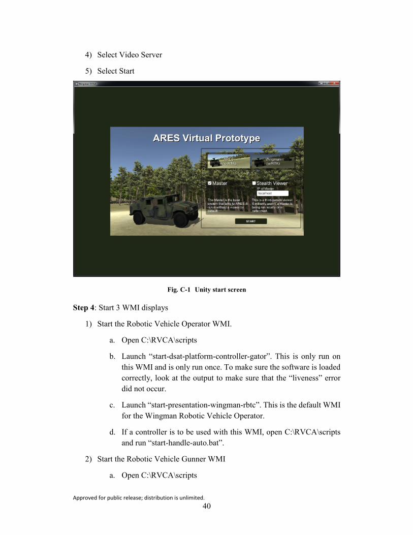
Approved for public release; distribution is unlimited. 40
4) Select Video Server
5) Select Start
Fig. C-1 Unity start screen
Step 4: Start 3 WMI displays
1) Start the Robotic Vehicle Operator WMI.
a. Open C:\RVCA\scripts
b. Launch “start-dsat-platform-controller-gator”. This is only run on this WMI and is only run once. To make sure the software is loaded correctly, look at the output to make sure that the “liveness” error did not occur.
c. Launch “start-presentation-wingman-rbtc”. This is the default WMI for the Wingman Robotic Vehicle Operator.
d. If a controller is to be used with this WMI, open C:\RVCA\scripts and run “start-handle-auto.bat”.
2) Start the Robotic Vehicle Gunner WMI
a. Open C:\RVCA\scripts

Approved for public release; distribution is unlimited. 41
b. Launch “start-ares-mrzr.bat”
c. Launch “start-presentation-wingman-ares.bat”
d. Launch “ares_joystick.bat”
3) Start the Commander WMI.
a. Open C:\RVCA\scripts.
b. Launch “start-presentation-wingman-cmdr”.
Step 5: Set Up System Connections
1) Set up vehicle localization and path plan in the Robotic Vehicle Operator WMI.
a. In order to set up a waypoint plan to move the vehicle from the WMI, select the “plan” button (right side of screen”, select “point” to place waypoints, and “close” to exit out of the planning mode.
b. Select “load into vehicle” button located halfway down the right side of the screen to connect the path to the vehicle.
c. Select the “assets” button on the bottom left of screen and “log in” to the vehicle (located on the middle screen, top button).
d. Select the “mobility” button at the bottom of the screen and select “plan” (looks like a “play” button symbol).
e. To move under teleoperation, select assets button and select the vehicle, log in to the vehicle, go to the mobility screen, and select “idle”. Select the steering-wheel icon and drag up to the teleoperation box.
f. To move under a preplanned path, select “File” on the map screen. Select the preplanned path (e.g., Grayling wpt xml demo/open). Select “load” button on right side of the screen and the steering wheel. To start the vehicle on the path, select the “WPT” button. To stop, select “pause”.
2) After the Unity simulation and Robotic Vehicle Gunner WMI are started, confirm that ARES is “talking” with the virtual Picatinny Light Weight Remote Weapon Station. To do this, click on the “Keyboard Input” window on the ARES machine and press “p” on the keyboard. In the Robotic Vehicle Gunner WMI, the weapon should begin to be raised to the “surveillance mode” position (roughly 45° above the horizon). Next press

Approved for public release; distribution is unlimited. 42
“a” in the “Keyboard Input” window. This will arm the weapon and lower it to its original position.
3) Check the Robotic Vehicle Gunner gamepad controller functionality:
a. Left bumper with the right joystick moves the weapon system.
b. Right bumper is the laser range finder.
c. The “a” button cycles the gun slew rate.
d. The “x” button selects a target with a green box.
e. The “y” button removes the target selection box.
f. The dpad “up” button zooms out.
g. The dpad “down” button zooms in.

Approved for public release; distribution is unlimited. 43
List of Symbols, Abbreviations, and Acronyms
2-D 2-dimensional
3-D 3-dimensional
ANVEL Autonomous Navigation and Virtual Environment Laboratory
ARES Autonomous Remote Engagement System
ARL US Army Research Laboratory
FCC Federal Communications Commission
GB gigabyte
GDAL Geospatial Data Abstraction Library
GeoTIFF Georeferenced Tagged Image File Format
HID Human Interface Device
HMMWV High Mobility Multipurpose Wheeled Vehicle
IP Internet Protocol
JCTD Joint Capabilities Technology Demonstration
LIDAR light detection and ranging
MHz megahertz
MUM-T manned-unmanned teaming
NSWCDD Naval Surface Warfare Center Dahlgren Division
OGRE Object-Oriented Graphics Rendering Engine
OS operating system
RAM random-access memory
ROS Robotic Operating System
RTK Robotic Technology Kernel
SIL software-in-the-loop
SSD solid-state drive
TARDEC Tank Automotive Research, Development and Engineering Center

Approved for public release; distribution is unlimited. 44
VM virtual machine
WMI Warfighter Machine Interface

Approved for public release; distribution is unlimited. 45
1 DEFENSE TECHNICAL (PDF) INFORMATION CTR DTIC OCA 2 DIR ARL (PDF) IMAL HRA RECORDS MGMT RDRL DCL TECH LIB 1 GOVT PRINTG OFC (PDF) A MALHOTRA 1 ARL (PDF) RDRL HRB B T DAVIS BLDG 5400 RM C242 REDSTONE ARSENAL AL 35898-7290 8 ARL (PDF) SFC PAUL RAY SMITH CENTER RDRL HRO COL H BUHL RDRL HRF J CHEN RDRL HRA I MARTINEZ RDRL HRR R SOTTILARE RDRL HRA C A RODRIGUEZ RDRL HRA B G GOODWIN RDRL HRA A C METEVIER RDRL HRA D B PETTIT 12423 RESEARCH PARKWAY ORLANDO FL 32826 1 USA ARMY G1 (PDF) DAPE HSI B KNAPP 300 ARMY PENTAGON RM 2C489 WASHINGTON DC 20310-0300 1 USAF 711 HPW (PDF) 711 HPW/RH K GEISS 2698 G ST BLDG 190
WRIGHT PATTERSON AFB OH 45433-7604
1 USN ONR (PDF) ONR CODE 341 J TANGNEY 875 N RANDOLPH STREET BLDG 87 ARLINGTON VA 22203-1986 1 USA NSRDEC (PDF) RDNS D TAMILIO 10 GENERAL GREENE AVE NATICK MA 01760-2642
1 OSD OUSD ATL (PDF) HPT&B B PETRO 4800 MARK CENTER DRIVE SUITE 17E08 ALEXANDRIA VA 22350 ABERDEEN PROVING GROUND 19 DIR ARL (PDF) RDRL HR C LANE J LOCKETT P FRANASZCZUK K MCDOWELL K OIE RDRL HRB D HEADLEY RDRL HRB C J GRYNOVICKI RDRL HRB D C PAULILLO RDRL HRF A A DECOSTANZA RDRL HRF B A EVANS RDRL HRF C J GASTON RDRL HRF B LANCE RDRL HRF D A MARATHE C LENNON S HILL K SCHAEFER-LAY RDRL VTA H EDGE M FIELDS R BREWER 3 DIR TARDEC (PDF) RDTA RTI GVR K BRIGGS T UDVARE E CERAME 5 DIR NSWCDD (PDF) CO NSWCDD H33 R POFF T HARRIS L BEALE B WHEELER E R PURSEL

Approved for public release; distribution is unlimited. 46
4 DCS CORP (PDF) B WOOD X NHAM J SONG A ZIMMERMANN