advanced welding technology
TRANSCRIPT

ADVANCED WELDING TECHNOLOGY
By:-HEMANT KUMAR
SYLLABUS
Unit-I1. Introduction: Importance and application of welding classification of welding process. Selection of welding process.2. Brief review of conventional welding process: Gas welding Arc welding MIG & TIG welding Resistance welding Electroslag welding Friction welding.3. Welding of Steel, CI, Al, Stainless steel4. Maurer/ Schaefflar Diagram. 5. Soldering & Brazing.

Welding Definition & ClassificationWelding Definition & Classification Process of permanent joining two materials (usually metals) through Process of permanent joining two materials (usually metals) through
localised coalescence of heat or force.localised coalescence of heat or force.
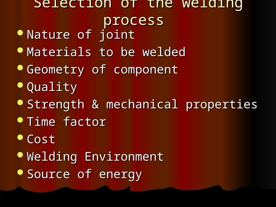
Selection of the welding processSelection of the welding process Nature of jointNature of jointMaterials to be weldedMaterials to be weldedGeometry of componentGeometry of componentQualityQualityStrength & mechanical propertiesStrength & mechanical propertiesTime factorTime factorCostCostWelding EnvironmentWelding EnvironmentSource of energySource of energy
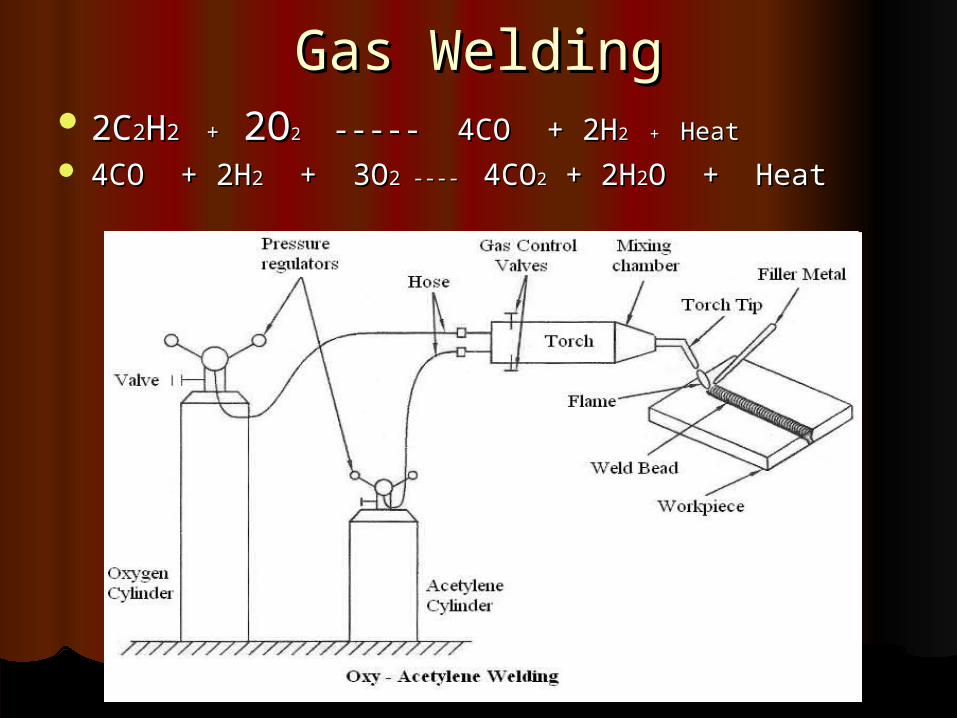
Gas WeldingGas Welding 2C2C22HH2 +2 + 2O 2O2 2 ----- 4CO + 2H----- 4CO + 2H2 + 2 + HeatHeat
4CO + 2H4CO + 2H22 + 3O + 3O2 ---- 2 ---- 4CO4CO22 + 2H + 2H22O + HeatO + Heat


Types of FlamesTypes of Flames
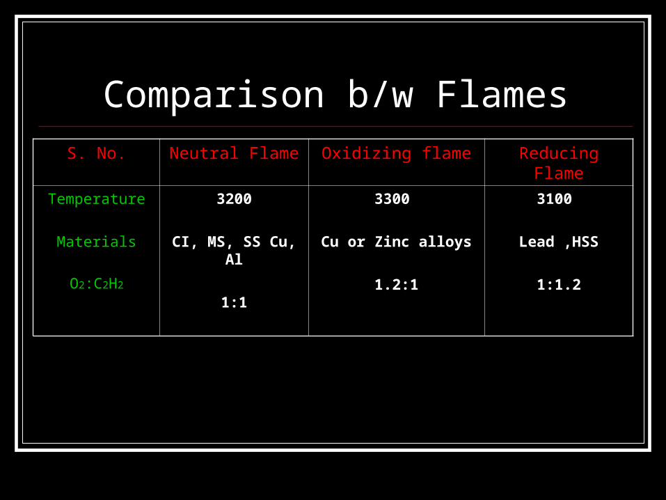
Comparison b/w FlamesS. No. Neutral Flame Oxidizing flame Reducing Flame
Temperature
Materials
O2:C2H2
3200
CI, MS, SS Cu, Al
1:1
3300
Cu or Zinc alloys
1.2:1
3100
Lead ,HSS
1:1.2
Oxy- Fuel Welding Oxygen is used with other fuel gas to
produce flame & coalescence of heat.
1. Hydrogen2. Propane3. Butane4. Natural gas
Advantage
Most versatile. Considerable control over temp. by varying supply of gases. Deposition rate is controlled Low cost & versatile equipment Portable & low maintenance
Disadvantage Not for heavy sections Lower temp of flame limits its use. Flux used causes irritating smoke. Refractory metals & reactive metals cannot be welded Long heat up time Larger HAZ More safety & handling problem with gases.

APPLICATION
Joining up to thickness 8 mm. Materials having harmful effect of rapid heating &
cooling. Materials like- CI, SS, LCS, HCS, Cu,
Zn, Ni, Mg etc. In automobile & aircraft industry for sheet-metal
applications.
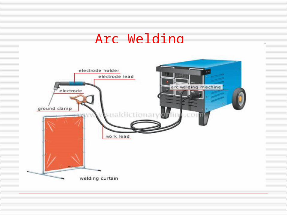
Arc Welding

PRINCIPLE Heat is generated from arc struck between
an electrode & work piece. Temp.= 5500 Celsius Stand off dis.= 1 - 5 mm. Arc length = 0.6 - 0.8 of electrode dia. Current =150 – 1000 Amp. Voltage = 40 - 45 volts (DC) 50 -60 volts (AC)
ARC GENERATION
Supply is on, voltage is applied, electrode & w/p are stuck together and hence current flow starts; then the electrode is kept 2-5mm and due to current flow electron jumps gap & ionization of gap takes place and arc is initiated.
Methods to initiate arc:1. TOUCH METHOD2. PASS-AWAY METHOD

Varients
1. Carbon Arc Welding.2. Shielded Metal Arc Welding. 3. Submerged Arc Welding.4. TIG (or GTAW) Welding. 5. MIG (or GMAW) Welding. 6. Electroslag Welding. 7. Electro gas Welding. 8. Plasma Arc Welding. 9. Arc Spot Welding. 10. Stud (Arc) Welding.

Tungsten Inert Gas ARC WELDING
(TIG/GTAW) • Heat is generated by electric arc struck
between a tungsten electrode and the job.• A shielding gas (argon helium, nitrogen,
etc.) is used to avoid atmospheric contamination of the molten weld pool.
• A filler metal may be added, if required.


SPECIFICATION 0f TIG• Temp. = 5500 Celsius• Welding torch angle= 70- 80 degrees• Filler rod angle= 10-20 degree• Current= 100-500 Amp• Electrode diameter = 2-5 mm• Filler rod diameter = 2-6 mm• Flow rate of gases = 7-11 lit/minutes• Electrode material = W, W alloys,
Thoriated W, Zerconiated W.• Shielding gases = Ar, Ne, He etc
ADVANTAGE
Applicable to wide range of materials (ferrous & non-ferrous).
Good for welding thin sections (0.125mm) and delicate work pieces
high quality and appearance of weld. Clear visibility No flux entrapment risk
DISADVANTAGE Restricted to flat or horizontal welding. W in weld pool causes seviour problem Filler rod end causes contamination of
weldment Costly.
APPLICATION
Al, Mg, Cu, Ni, and their alloys. Carbon alloys, SS, High temp &
hard surfacing alloys like Zr, Ti. Welding thinner sections. Welding of expansion bellows,
transistor cases, instrument diaphragm & sealing joints
Rocker motor chamber fabrication in launch vehicles.

METAL INHERT GAS ARC WELDING
(MIG)• Heat is generated by electric arc struck between a
consumable metal electrode and the job.• A shielding gas (argon helium, nitrogen, etc.) is
used to avoid atmospheric contamination of the molten weld pool.
• It needs Wire Electrode feed mechanism.
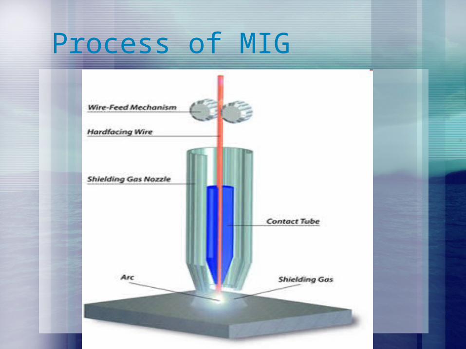
Process of MIG

ADVANTAGE Versatility - readily applied to a variety
of applications and a wide choice of electrodes
Relative simplicity and portability of equipment
Low cost Adaptable to confined spaces and
remote locations Suitable for out-of-position welding

DISADVANTAGE Not as productive as continuous wire
processes Likely to be more costly to deposit a given
quantity of metal Frequent stop/starts to change electrode Relatively high metal wastage (electrode
stubs) Current limits are lower than for continuous or
automatic processes (reduces deposition rate)
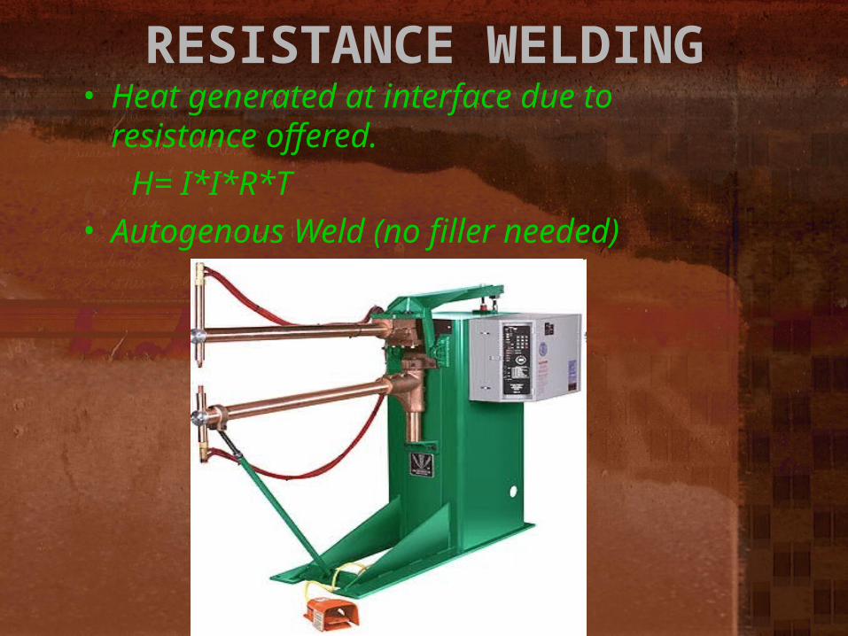
RESISTANCE WELDING• Heat generated at interface due to
resistance offered. H= I*I*R*T• Autogenous Weld (no filler needed)
Variants
Spot welding Seam welding Projection welding Upset/Butt welding Flash Butt welding Percussion welding
Electrode Material
0.99Cu 0.1Cd- LCS, Al & Mg alloy. 0.992Cu 0.8Cr- SS, Ni alloy, Ni plated
steel 0.05Be 0.1Ni 0.1Co 0.975Cu- Low
electrical & high thermal conducting materials.
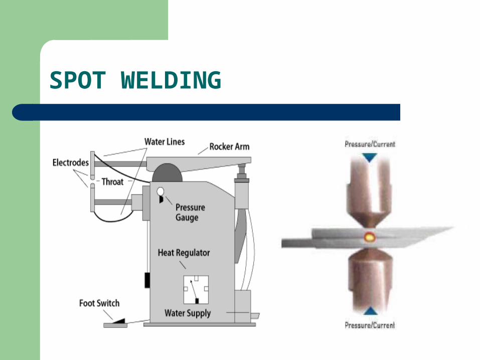
SPOT WELDING

Welding steps SQUEEZE TIME- Both workpices are
squeezed together, by app of pressure by electrodes.
CURRENT SUPPPLY- Now welding current is applied for short time.
HOLD TIME- Current is off but the forces remains applied for proper weld.
OFF TIME- the forces on the work is removed.
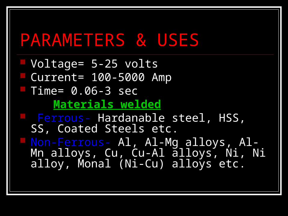
PARAMETERS & USES Voltage= 5-25 volts Current= 100-5000 Amp Time= 0.06-3 sec Materials welded Ferrous- Hardanable steel, HSS, SS,
Coated Steels etc. Non-Ferrous- Al, Al-Mg alloys, Al-Mn alloys,
Cu, Cu-Al alloys, Ni, Ni alloy, Monal (Ni-Cu) alloys etc.
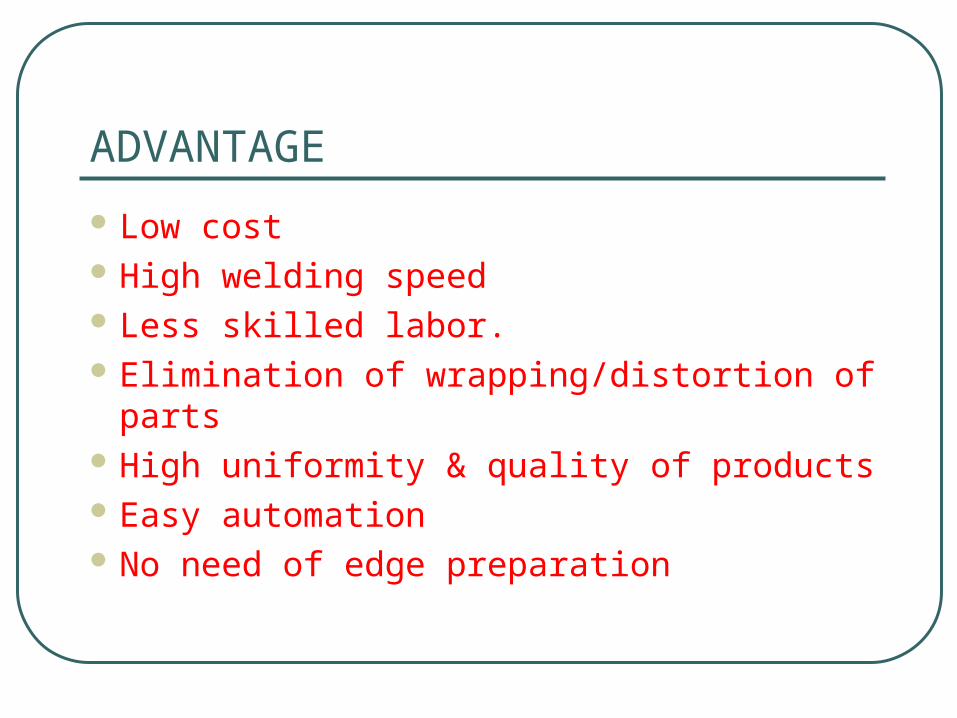
ADVANTAGE
Low cost High welding speed Less skilled labor. Elimination of wrapping/distortion of
parts High uniformity & quality of products Easy automation No need of edge preparation
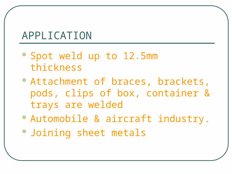
APPLICATION
Spot weld up to 12.5mm thickness Attachment of braces, brackets,
pods, clips of box, container & trays are welded
Automobile & aircraft industry. Joining sheet metals
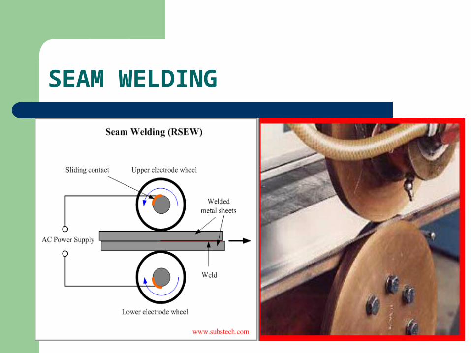
SEAM WELDING

ADVANTAGEADVANTAGE Gas & liquid tight Gas & liquid tight
welds.welds. Overlap may be less Overlap may be less
than spot weldingthan spot welding Single seam weld or Single seam weld or
parallel welds can parallel welds can be producedbe produced
DISADVANTAGEDISADVANTAGE ONLY STRAIGHT OR ONLY STRAIGHT OR
UNIFORM CURVE CAN UNIFORM CURVE CAN BE WELDEDBE WELDED
DIFFICULT TO WELD DIFFICULT TO WELD THICKNESS MORE THICKNESS MORE THAN 3MMTHAN 3MM
SPECIAL DESIGNE OF SPECIAL DESIGNE OF WELD ROLLSWELD ROLLS
APPLICATION•ROUND, SQUARE, RECTANGULAR WELDS•EXPECT Cu & HIGH Cu ALLOYS ALL OTHER MATERIALS ARE WELDED•CAN BE USED FOR LAP, BUTT JOINTS

PROJECTION WELDINGPROJECTION WELDING

PRINCIPLEPRINCIPLE
Current flow is concentrated at Current flow is concentrated at the contact surface by an the contact surface by an embossed projection.embossed projection.
Projection effectively localizes the Projection effectively localizes the currentcurrent

ADVANTAGE
No of simultaneous weld Thick joints Less interference by rust, oil & work
coating Long electrode life Can be used for complicated shapes Better heat balance Lower current & pressure
DISADVANTAGE
Limited to metals which can be embossed
For proper weld all projection must have equal height.

APPLICATON
Various automobile parts Small fasteners & nuts can be
welded Refrigerator condenser Cross wire welding Grating of boilers Household grills.
FRICTION WELDING
• solid-state welding• Heat through mechanical friction
b/w a moving work piece & a stationary component .
• Technically, because no melt occurs, so its a forging technique .
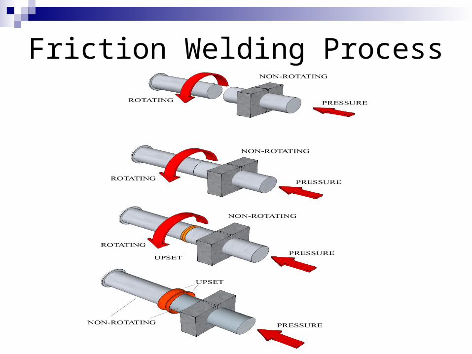
Friction Welding Process
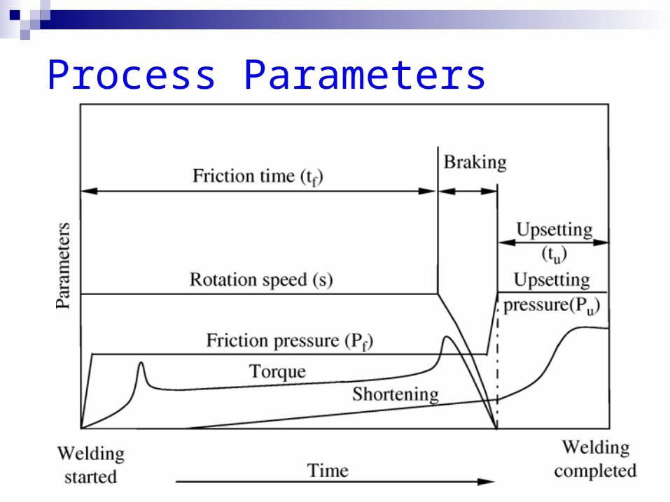
Process Parameters

Process Specification
Peripheral velocity= 50-200 m/min Axial pressure= 30-200 N/mm2 Material Welded- Al, Ti, Ni, Cu and
their alloys, Brass, Bronze, Mg, Carbon steel, SS, Tantalum etc..
Dissimilar material welds- Alloy steel to carbon steel, super alloys to carbon steel, SS to carbon steel

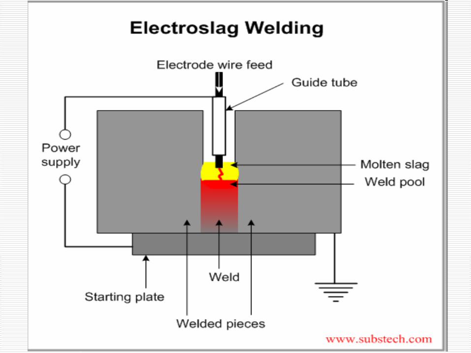
ELECTROSLAG WELDING
• Highly productive, single pass process (thickness 25-300 mm) in a vertical position
• Arc is initially struck by wire fed into the weld location & then flux is added.
• Additional flux is added until the molten slag extinguishes the arc.
• The wire is then continually fed and the filler metal are then melted using the electrical resistance of the molten slag to cause coalescence.

Processes
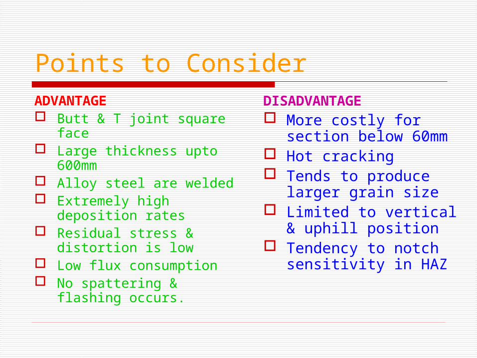
Points to ConsiderADVANTAGE Butt & T joint square
face Large thickness upto
600mm Alloy steel are welded Extremely high
deposition rates Residual stress &
distortion is low Low flux consumption No spattering & flashing
occurs.
DISADVANTAGE More costly for
section below 60mm Hot cracking Tends to produce
larger grain size Limited to vertical &
uphill position Tendency to notch
sensitivity in HAZ

APPLICATION
Heavy casting, forging plates (butt weld)
Welding of thick LCS & MCS. High strength structure steel Large cross-section of flyovers,
structures, marine ships etc.
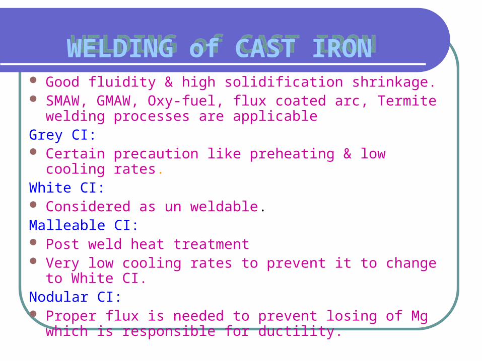
WELDING of CAST IRONWELDING of CAST IRON Good fluidity & high solidification shrinkage. SMAW, GMAW, Oxy-fuel, flux coated arc, Termite
welding processes are applicableGrey CI: Certain precaution like preheating & low cooling rates.White CI: Considered as un weldable.Malleable CI: Post weld heat treatment Very low cooling rates to prevent it to change to
White CI.Nodular CI: Proper flux is needed to prevent losing of Mg which is
responsible for ductility.

WELDING of ALUMINIUMWELDING of ALUMINIUMHigher heat input needed (Reverse DC
polarity)Thick sections needs preheatingHigh reflective hence no red colour is
appered during heatingGMAW, GTAW, Resistance welding is
common. PAW, EBM are specially usedSMAW & oxy fuel welding are used
when strength is not essential

WELDING of STEELWELDING of STEEL
LCS(0.13-0.3 %C): arc welding is preferredMCS(0.3-0.5 %C): Pre weld heat treatment is common Post weld heat treatment is sometimes necessary for
thin sectionsHCS(0.5-1.5%C): Pre & Post weld eat treatment is essential Low H, S welding process Should be welded in annealed conditionHIGH STRENGTH LOW ALLOY STEELS: SMAW, TIG/MIG, Flux coated ,Submerged arc welding
are applicable. Low Hydrogen welding Resistance welding can be applied
SOLDERINGSOLDERING• Two or more metal items are joined
together by melting and flowing a filler metal into the joint
• The filler metal having a relatively low melting point
• Soldering is characterized by the melting point of the filler metal, is below 400 °C
• The filler metal used in the process is called SOLDER
• It is distinguished from welding by the base metals not being melted during the joining
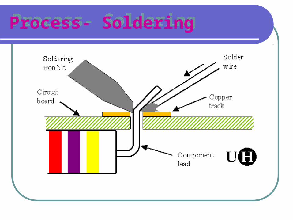
Process- SolderingProcess- Soldering
ApplicationApplication
Assembling electronic components to printed circuit boards
Permanent but reversible connections between copper pipes in Plumbing systems
Jewelry components are assembled and repaired by soldering
Solders Solders
tin-lead (general purpose) tin-zinc for joining aluminum lead-silver for strength at higher than
room temperature cadmium-silver for strength at high
temperatures zinc-aluminum for aluminum and
corrosion resistance tin-silver and tin-bismuth for
electronics
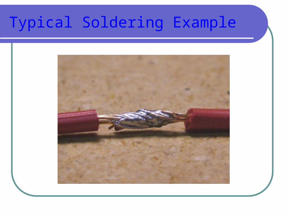
Typical Soldering Example
