advanced water recovery technologies for long duration
TRANSCRIPT
Advanced Water Recovery Technologies for Long Duration Space ExplorationMissions
Final ReportNASA Faculty Fellowship Program - 2004
Johnson Space Center
Prepared by: Sean X. Liu, Ph.D.
Academic Rank: Assistant Professor
University & Department Rutgers UniversityDepartment of Food Science65 Dudley RoadNew Brunswick, NJ 08901
NASA/JSC
Directorate: Engineering
Division: Crew and Thermal System Division
Branch: Advanced Life Support Office
JSC Colleague: Daniel J. Barta, Ph.D.
Date Submitted: August 9, 2004
Contract Number: NAG 9-1526 and NNJ04JF93A
16-1
ABSTRACT
Extended-duration space travel and habitation require recovering water from wastewatergenerated in spacecrafts and extraterrestrial outposts since the largest consumable forhuman life support is water. Many wastewater treatment technologies used for terrestrialapplications are adoptable to extraterrestrial situations but challenges remain asconstraints of space flights and habitation impose severe limitations of thesetechnologies. Membrane-based technologies, particularly membrane filtration, have beenwidely studied by NASA and NASA-funded research groups for possible applications inspace wastewater treatment. The advantages of membrane filtration are apparent: it isenergy-efficient and compact, needs little consumable other than replacement membranesand cleaning agents, and doesn't involve multiphase flow, which is big plus foroperations under microgravity environment. However, membrane lifespan andperformance are affected by the phenomena of concentration polarization and membranefouling. This article attempts to survey current status of membrane technologies related towastewater treatment and desalination in the context of space exploration and quantifythem in terms of readiness level for space exploration. This paper also makes specificrecommendations and predictions on how scientist and engineers involving designing,testing, and developing space-certified membrane-based advanced water recoverytechnologies can improve the likelihood of successful development of an effectiveregenerative human life support system for long-duration space missions.
16-2
INTRODUCTION
Water is essential to all lives. Currently, potable water has been provided fully forthe entire duration of the mission to all manned low orbit space missions including SpaceShuttle and International Space Station (ISS) missions. The wastewaters generated incurrent space-related missions, including urine, hygiene water, and condensate water, areeither discharged into space or brought back to the earth (although there is limited waterrecovery of certain streams of space wastewater in ISS, the recovered water is not used aspotable water). This arrangement of water supply for long-duration manned spacemissions would be, of course, unattainable. And wastewater recycling becomes anessential part of Environmental Control and Life Support Systems (ECLSS) for all long-duration space exploration missions. Many terrestrial wastewater treatment technologiescan be potentially adopted for extraterrestrial applications. However, many challengesneed to be overcome in order to converting wastewaters to potable water as required byextended duration space exploration.
The main challenge of human presence in space is to duplicate the criticalfunctions of intricate, interdependent processes that occur and sustain lives on earth. Thewater aspect of this challenge is to completely recover potable water from wastewatergenerated in the outer space with no need of water replenishment and substantial amountof consumables in a restricted and confined microgravity environment. Outer space is anunforgiving and daunting place, far away from any help from the earth, and this puts ahuge premium on reliability and easiness of maintenance of water recovery systems.Microgravity introduces another dimension to an already-difficult problem in wastewatertreatment in space exploration. Forces that are small in terrestrial flow situations such assurface tension become dominant while buoyancy is absent in a weightless environment.Flotation and sedimentation, for example, two common and inexpensive wastewatertreatment processes, have no use in a microgravity environment. Some of other commonwastewater treatment unit operations have to be modified to address solid/liquid,gas/liquid, and gas/solid separations in the form of additional equipment or/andprocesses. The difficulty of wastewater treatment associated with microgravity is alsoextended to the issues of process scale-up and modeling/simulation. All process models,past or current, theoretical or empirical, are subject to validation in space because ofmicrogravity factor. The cost of doing that is so prohibitive that there have been fewattempts made to field-test the equipment or design.
The labeling of"microgravity compatible" technologies for water treatment areoften based on whether the technology in question is mono-phased and/or whethergravity plays any significant role in driving process performance. This approach isimprecise and sometimes questionable since it ignores the forces such as surface tensionthat are insignificant under normal gravity but are important in the microgravityenvironment. The uniqueness of microgravity environment has unsettling implications onvarious water treatment processes where the bulk fluid is mono-phased but involvedsolid-fluid interfaces between the fluid and the material of the equipment. One such a
16-3
sample is membrane filtration that is being used in ISS for water recovery from hygienewater and humidity condensate. There is no evidence yet to suspect that microgravity hasadverse effect on operability of the reverse osmosis unit, however, no one can rule out thepossibility of adverse effect of surface tension on membrane filtration at the membranesurface and/or in the boundary layer since surface tension is manifested at interfaces,where concentration polarization and membrane fouling occur.
Recognizing the gap between a basic process of a particular water processingtechnology and an on-board water treatment module for extended-duration spacemissions, NASA has devised a systematic assessment scheme, called TechnologyReadiness Level (TRL), to assess the maturity of a technology for all space-boundtechnologies, making comparison of sophistication levels among different technologiesdesigned for a particular application of space exploration. For each technology, the largerthe number of TRL, the closer the technology is eligible for being used for spacemissions. The definitions of TRL are can be found in many NASA documents (White,1995).
MEMBRANE SEPARATION TECHNOLOGIES FOR WATER RECOVERY
Membrane Filtration
Membrane filtration is a technology that utilizes semi-permeable materials in aspecific arrangement (configuration) to exclude most organic or inorganic maters inwastewaters based on size or molecular weight while allowing water and, for somevariations of membrane filtration systems, small molecules to permeate through. Themost common variations of membrane filtration are based on the ability of a membrane toreject materials of certain range of size and/or molecular weight (Liu, 2003). Membranefiltration technology for water treatment has advanced rapidly as demand for potablewater worldwide increases. The last two decades have witnessed new reverse osmosis
membrane materials that can be operated at ever lower pressure and with increasing saltrejection. Current commercial membranes for reverse osmosis have been claimed to have97% - 99.5% salt rejection rate (usually obtained from lab-scale membrane units withNaC1 solution) and 7 bar operating net driving pressure (Nicolaisen, 2002). Realistically,many reverse osmosis water treatment plants operate at much lower salt rejection rate(about 50 % - 75%) as concentration polarization and fouling take their tolls. The effectof the "evil twin," concentration polarization and fouling, on potable water productionfrom brackish water and seawater is significant and has limited the wide acceptance inthe U.S. as a main water treatment technology because of high energy cost and disposalissue related to the concentrated brine from reverse osmosis plants. In long-durationspace missions, however, the requirement for water recovery from space wastewater isideally 100% (not accounting for additional water from foods). This would require eitherthe development of low-pressure and less prone to fouling membranes situated in amembrane module that has minimal concentration polarization in operation orincorporation and optimization of several membrane processes or/and other separation
16-4
technologies into water recovery systems. Various membrane separation types incommon uses have different possible TRL rating with microfiltration (MF) at the highend, and ultrafiltration (UF) and reverse osmosis (RO) in the middle range of the TRLspectrum.
MF is a pressure-driven membrane filtration process that has a membrane with apore size typically of 0.01-2 gm and able to retain particles with molecular weights equalor larger than 200 kDa and is used in a number of applications, as either a pre-filtrationstep or as a process to separate a fluid from a process stream. MF membranes aresymmetric with characteristic sponge-like network of interconnecting pores. Cartridgefilters are typically composed of microfiltration media. Multi-units of MF have been usedin spacecrafts and habitats including MIR and ISS as a pretreatment unit for subsequentwater processors such as vapor-compression distillation. MF as pretreatment processcould be considered as TRL 8 or 9 technologies.
UF involves the use membrane with a pore size less than 0.1 _m (500 - 100 kDa).Ultrafiltration is not as fine a filtration process as reverse osmosis, but it also does notrequire the same energy to perform the separation. Applications of ultrafiltration in waterrecovery for space adventures can mostly likely be found in situations where pretreatmentis needed for reducing or removing certain compounds from the feed stream of a reverseosmosis unit in order to alleviate the energy demand and fouling. In UF, the chemicalnature of membrane materials has only little effect upon the separation (but not fouling)since ultrafiltration separation like microfiltration is based upon sieving mechanisms thusultrafiltration is only somewhat dependent upon the charge of the particle and is muchmore concerned with the size of the particle.
The presence of large quantity of mixed surfactants in space wastewater poses aunique problem for ultrafiltration. On the one hand, micellar-enhanced ultrafitration iswidely credited for removing certain particulates and solutes that would be impossible tobe removed without the assistance of surfactant aggregates, micelles; on the other hand,surfactant monomers are believed to be responsible for membrane fouling by adhering tothe membrane surface. The susceptibility of UF membranes to fouling by proteins hasgenerated interests in fundamental studies in membrane fouling. It is no surprising to seeprevalence of fouling in these applications since polymeric UF membranes (polysulfone,for instance) are more or less hydrophobic and proteins have tendency to adhere theirhydrophobic cores to the membrane surface thus forming a strong bond - irreversiblefouling. In space wastewater treatment, however, membrane fouling is mainly caused bydeposition of minerals on the surface and blockage of the pores in addition to adsorptionof surfactant monomers, and biofouling. The extent of mineral fouling in relation tosurfactant fouling is yet to be determined. Biofouling of UF and other membranes isanother important subject that is not adequately studied. In addition to composition ofwastewater feed stream, the membrane surface characteristics are the most importantfactors that determine the extent of biofouling. One recent paper (Vrijenhoek et al., 2001)suggested that the smoothness of the RO membrane surface had a lot to do with whether
16-5
biofilms would form on the membrane because, they argued, without crevices or holes orfolds, it is difficult to for microorganisms to establish their colonies. This conclusionobviously needs to be further studied. But even the above argument is accurate; one hasto wonder if it is also applicable to ultrafiltration since UF membranes contain relativelylarge-sized pores.
RO, also known as hyperfiltration, is the finest filtration known. This process willallow the removal of particles as small as ions from a solution. Reverse osmosis is usedto purify water and remove salts and other impurities in order to improve the color, tasteor properties of the fluid. Most reverse osmosis technology uses a process known ascross-flow to allow the membrane to continually clean itself. As some of the fluid passesthrough the membrane the rest continues downstream, sweeping the rejected speciesaway from the membrane. The process of reverse osmosis requires a driving force topush the fluid through the membrane, and the most common force is pressure from apump. A reverse osmosis process involves pressures 5-10 times higher than those used inultrafiltration. As the concentration of the fluid being rejected increases, the driving forcerequired continuing concentrating the fluid increases. Reverse osmosis is capable ofrejecting bacteria, salts, sugars, proteins, particles, fats, and other constituents that have amolecular weight of greater than 0.15-0.25 kDa. The separation of ions with reverseosmosis is aided by charged particles. This means that dissolved ions that carry a charge,such as salts, are more likely to be rejected by the membrane than those that are notcharged, such as organics. The larger the charge and the larger the particle, the morelikely it will be rejected. The transport mechanism of RO is now believed to be thesolution diffusion mechanism.
Other Membrane Processes
There are several other membrane processes that involve separate dissolvedspecies from water. Among them are pervaporation and membrane distillation.Pervaporation is defined as a separation process in which a liquid feed mixture isseparated by means of partial diffusion-vaporization through a non-porous polymericmembrane while vacuum or a sweep gas is applied to the downstream side of themembrane. Membrane pervaporation has been used in removal of VOC fromgroundwater and wastewater (for example, Peng et al., 2003; Peng and Liu, 2003ab) andin removal of water from highly-concentrated alcohol (for example, Verkerk et al., 2001).The strength of pervaporation technology lies in its ability to separate trace amount ofcomponent(s) from the remaining components in the bulk liquid with less energyrequirement and high recovery rate than other separation technologies including othermembrane processes. The potential application of pervaporation and its cousin processessuch as temperature swing adsorption and thick film absorption in space wastewatertreatment is limited to dehydration of the high concentrated brine discharged from an ROunit. It should be noted that the issues such as concentration polarization and membranefouling also affect pervaporation. Scaling of minerals is a potentially worrisome problemsince many pervaporation units operate at 30 - 50 °C to be most effective.
16-6
Membrane distillation is another membrane technology that can be used as a partof water recovery system. Membrane distillation (MD) is a type of low temperature,reduced pressure distillation using porous hydrophobic polymer materials. It is a processthat separates two aqueous solutions at different temperatures and has been developed forthe production of high-purity water, and for the separation of volatile solvents such asacetone and ethanol. MD can achieve higher concentration than RO. In MD, themembrane must be hydrophobic and microporous. The hydrophobic nature of thematerial prevents the membrane from being wetted by the liquid feed and hence liquidpenetration and transport across the membrane is avoided, provided the feed side pressuredoes not exceed the minimum entry pressure for the pore size distribution of themembrane. The driving force of MD is temperature gradient and the two differenttemperatures produce two different partial vapor pressures at the solution-membraneinterface, which propels consequent penetration of the vapor through the pores of themembrane. The vapor is condensed on the chilled wall by cooling water, producing adistillate. This process usually takes place at atmospheric pressure and temperature thatmay be much lower than the boiling point of water. Membrane could be used tocompliment a hybrid membrane process such as UF-RO unit in space missions. Theeffect of microgravity on MD operations needs further research.
Membrane Materials
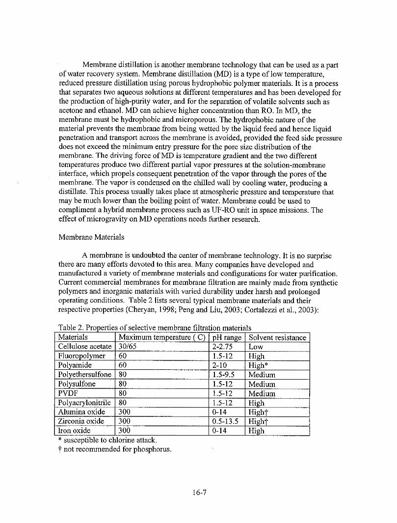
A membrane is undoubted the center of membrane technology. It is no surprisethere are many efforts devoted to this area. Many companies have developed andmanufactured a variety of membrane materials and configurations for water purification.Current commercial membranes for membrane filtration are mainly made from syntheticpolymers and inorganic materials with varied durability under harsh and prolongedoperating conditions. Table 2 lists several typical membrane materials and theirrespective properties (Cheryan, 1998; Peng and Liu, 2003; Cortalezzi et al., 2003):
Table 2. Properties of selective membrane filtration materialsMaterials Maximum temperature (C) pH range Solvent resistanceCellulose acetate 30/65 2-2.75 Low
Fluoropolymer 60 1.5-12 HighPolyamide 60 2-10 High*Polyethersulfone 80 1.5-9.5 MediumPolysulfone 80 1.5-12 MediumPVDF 80 1.5-12 Medium
Polyacrylonitrile 80 1.5-12 HighAlumina oxide 300 0-14 HightZirconia oxide 300 0.5-13.5 HightIron oxide 300 0-14 High* susceptible to chlorine attack.t not recommended for phosphorus.
16-7
The first-generation RO membrane materials such as cellulose acetate, thoughless prone to fouling, has seen its market share declining in desalination and wastewatertreatment operations due to newly arrived composite RO membranes. The fragility of thistype of membranes has ruled itself out in applications in space missions. Currently, thesecond-generation RO membranes such as composite membranes made from thinpolyamide active layer on top of UF or MF substrates made from polysulfone has beenadopted for seawater desalination. However, owing to different components in spacewastewater, the applicability of this type of materials remains unclear and needs furtherlong-term studies. Inorganic membranes represented by alumina oxide and zirconia oxide(third-generation) are very resistant to high temperature, organic solvents and acids.However, the processability and cost issues related to inorganic membranes are mainroad blocks to successful commercial applications. The potential applications ofinorganic membranes for space missions are not very encouraging now due to theprocessability issue. This situation could change with the improvements in processingtechniques. A current trend in membrane development is modification of membranesurface characteristics to achieve certain operational goals. Improvement inhydrophilicity by copolymerizing another monomer or functional group is a commontechnique to reduce membrane fouling by proteins or organic colloids. Another emergingarea of membrane materials is nanocomposite membrane. This type of membranematerials involve the use of polymeric materials as substrate embedded with nano-sizedproperty-enhancers such as carbon nanotubes.
Membrane Modules
Spiral wound
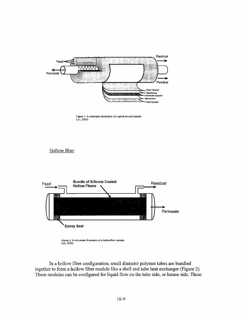
In spiral wound modules, a flat membrane envelope or set of envelopes is rolledinto a cylinder as shown in Figure 1. The envelope is constructed from two sheets ofmembrane, sealed on three edges and each sheet is sandwiched between two turbulent-promoting spacers. The open end of envelope is sealed to a perforated tube (the permeatetube) with a proper glue so that the permeate can pass through the perforations. Anotherspacer is laid on top of the envelope before it is rolled, creating the flow path for the feedliquid. This feed spacer generates turbulence, thereby enhancing the feed side masstransfer rate. The spiral wrapped envelopes and spacers are then wrapped again with tapeor glass or net-like sieve before fitting into a pressure vessel. In this way, a reasonablemembrane area can be housed in a convenient module, resulting in a very high surfacearea to volume ratio. One noticeable drawback lies in the permeate path length. Apermeating component that enters the permeate envelope farthest from the permeate tubemust spiral inward several feet. Depending upon the path length, permeate spacer design,gel layer, and permeate flux, significant permeate side pressure drops can be encountered.The other disadvantage of this module is that it is a poor choice for treating fluidscontaining particulate matters. This configuration is widely used in desalination plantswith RO and generally is well-suited for space wastewater treatment.
16-8
Residual
Residual
pacer
Feed Spacer
Figure 1. A schematic illustration of a spiral wound mOdule(Liu, 2003)
Hollow fiber
Bundle of Silicone Coated ResidualFeed Hollow Fibers I
I
Permeate
Seal
Figure 2. A schematic illustration of a hollow fiber module(Liu, 2003)
In a hollow fiber configuration, small diameter polymer tubes are bundled
together to form a hollow fiber module like a shell and tube heat exchanger (Figure 2).These modules can be configured for liquid flow on the tube side, or lumen side. These
16-9
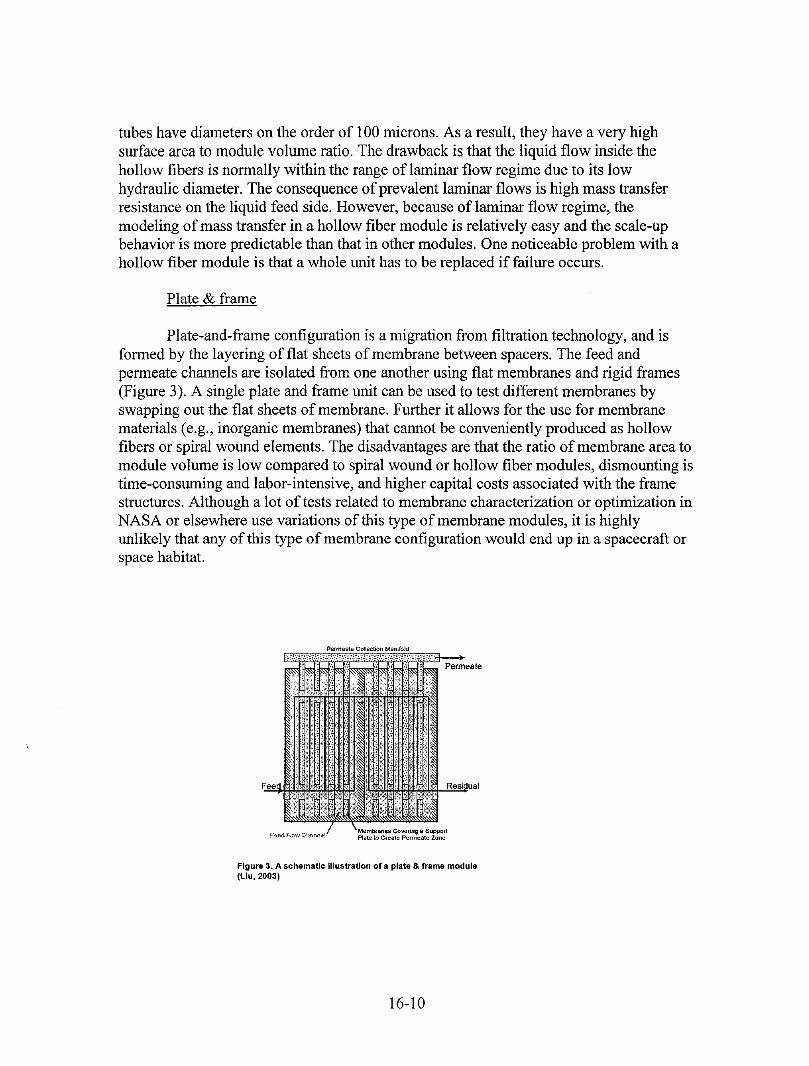
tubes have diameters on the order of 1O0microns. As a result, they have a very highsurface area to module volume ratio. The drawback is that the liquid flow inside thehollow fibers is normally within the range of laminar flow regime due to its lowhydraulic diameter. The consequence of prevalent laminar flows is high mass transferresistance on the liquid feed side. However, because of laminar flow regime, themodeling of mass transfer in a hollow fiber module is relatively easy and the scale-upbehavior is more predictable than that in other modules. One noticeable problem with ahollow fiber module is that a whole unit has to be replaced if failure occurs.
Plate & frame
Plate-and-frame configuration is a migration from filtration technology, and isformed by the layering of flat sheets of membrane between spacers. The feed andpermeate channels are isolated from one another using flat membranes and rigid frames(Figure 3). A single plate and frame unit can be used to test different membranes byswapping out the flat sheets of membrane. Further it allows for the use for membranematerials (e.g., inorganic membranes) that cannot be conveniently produced as hollowfibers or spiral wound elements. The disadvantages are that the ratio of membrane area tomodule volume is low compared to spiral wound or hollow fiber modules, dismounting istime-consuming and labor-intensive, and higher capital costs associated with the framestructures. Although a lot of tests related to membrane characterization or optimization inNASA or elsewhere use variations of this type of membrane modules, it is highlyunlikely that any of this type of membrane configuration would end up in a spacecraft orspace habitat.
PermeateCollecgonManifold
Permeate
g a support
Figure 3. A schematic illustration of a plate & frame module(Liu, 2003)
16-10
Tubuiar
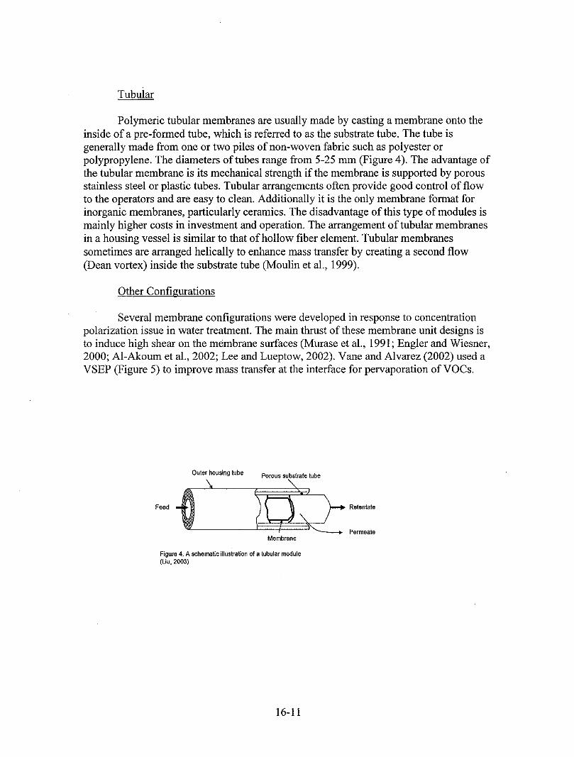
Polymeric tubular membranes are usually made by casting a membrane onto theinside ofa pre-formed tube, which is referred to as the substrate tube. The tube isgenerally made from one or two piles of non-woven fabric such as polyester orpolypropylene. The diameters of tubes range from 5-25 mm (Figure 4). The advantage ofthe tubular membrane is its mechanical strength if the membrane is supported by porousstainless steel or plastic tubes. Tubular arrangements often provide good control of flowto the operators and are easy to clean. Additionally it is the only membrane format forinorganic membranes, particularly ceramics. The disadvantage of this type of modules ismainly higher costs in investment and operation. The arrangement of tubular membranesin a housing vessel is similar to that of hollow fiber element. Tubular membranessometimes are arranged helically to enhance mass transfer by creating a second flow(Dean vortex) inside the substrate tube (Moulin et al., 1999).
Other Configurations
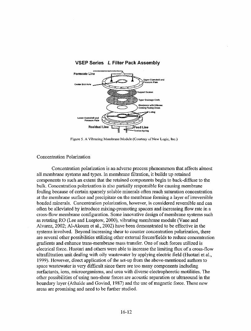
Several membrane configurations were developed in response to concentrationpolarization issue in water treatment. The main thrust of these membrane unit designs isto induce high shear on the membrane surfaces (Murase et al., 1991; Engler and Wiesner,2000; A1-Akoumet al., 2002; Lee and Lueptow, 2002). Vane and Alvarez (2002) used aVSEP (Figure 5) to improve mass transfer at the interface for pervaporation of VOCs.
Outer housing tube Porous substratetube
Feed *_ Retentate_------_ Permeate
Membrane
Figure 4. A schematic illustrationof a tubular module(Liu, 2003)
16-11
VSEP Series L Filter Pack Assembly
Permeate Line
Upper Clamshell andPressure Plate
Center Bolt Hole
Support Screen
Typar Drainage Cloth
Membrane with Siliconei Coating F&clng Down
Lower Clamshell andPressure Plate
Residual Line
Figure 5. A Vibrating Membrane Module (Courtesy of New Logic, Inc.)
Concentration Polarization
Concentration polarization is an adverse process phenomenon that affects almostall membrane systems and types. In membrane filtration, it builds up retainedcomponents to such an extent that the retained components begin to back-diffuse to thebulk. Concentration polarization is also partially responsible for causing membranefouling because of certain sparsely soluble minerals often reach saturation concentrationat the membrane surface and precipitate on the membrane forming a layer of irreversiblebonded minerals. Concentration polarization, however, is considered reversible and canoften be alleviated by introduce mixing-promoting spacers and increasing flow rate in across-flow membrane configuration. Some innovative design of membrane systems suchas rotating RO (Lee and Lueptow, 2000), vibrating membrane module (Vane andAlvarez, 2002; A1-Akoum et al., 2002) have been demonstrated to be effective in thesystems involved. Beyond increasing shear to counter concentration polarization, thereare several other possibilities utilizing other external forces/fields to reduce concentrationgradients and enhance trans-membrane mass transfer. One of such forces utilized iselectrical force. Huotari and others were able to increase the limiting flux of a cross-flowultrafiltration unit dealing with oily wastewater by applying electric field (Huotari et al.,1999). However, direct application of the set-up from the above-mentioned authors tospace wastewater is very difficult since there are too many components includingsurfactants, ions, microorganisms, and urea with diverse electrophoretic motilities. Theother possibilities of using non-shear forces are acoustic separation or ultrasound in theboundary layer (Athaide and Govind, 1987) and the use of magnetic force. These newareas are promising and need to be further studied.
16-12
Membrane Fouling
Fouling is a phenomenon of irreversible loss of membrane permeability leading toreduction in permeation flux. Fouling is caused by adsorption of feed components,clogging of the pores (UF and MF), chemical bonding reaction between the solutes andthe membrane, gel formation, and microbial growth and biofilm formation (Koltuniewiezand Noworyta, 1994). The major factors that influence membrane fouling are thehydrodynamics of the process, and the physicochemical properties of the membrane andthe feed solution (Huisman et al., 2000). Membrane fouling is a direct result ofinteraction between solutes in the feed stream and the membrane. As such, the propertiesof the membrane and solutes in the feed stream as well as operating parameters havestrong bearing on fouling. For a UF/MF membrane, the hydrophilicity, surfacetopography, charge on the membrane, and pore size contribute individually or in severalof combinations, to the fouling while organic colloids, pH, soluble minerals, andsurfactants appear to be the contributing factors from solutes in feed streams (Cheryan,1998). As alluded previously, proper selection or modification of membrane surface,pretreatment of membranes with certain surfactants and enzymes, and use of biocides canreduce fouling. The measures used to fight concentration polarization can also mitigatefouling since concentration polarization is partially responsible for fouling. Temperaturealso affects the extent of fouling (Goosen et al., 2002).
In addition to hydrophilicity, membrane surface topography and pore size alsoaffect the interaction between foulant molecules and the membrane thus membrane
fouling. Membrane surface morphology can influence the membrane fouling in twoways: the rough surface tends to trap macromolecules and the surface area of a roughmembrane is larger than that of a smooth membrane, which increases likelihood andnumber of protein adsorption sites. Additionally, in a cross-flow mode operation, afoulant molecule that deposits on a rough membrane surface is less likely to tear off fromthe surface. Pore size role in membrane fouling seems to be obvious. However, largepore size only gives initial high flux. Once foulants deposit onto the surface of the poreand aggregates are formed in the pore, the pore becomes constricted and lower fluxensues. If pore size is in the same magnitude as size of the molecules, the chance of themolecules clogging some of pores increases. Cheryan (1998) suggests a ratio of pore sizeto particle size of 1:10.
CONCLUDING REMARKS
Membrane separation technologies are the logic choice for space water recovery.Membrane filtration is a physical process that requires no additional chemicals and lessenergy than a typical thermal process, and is compact, modular, and perceivablyinsensitive to microgravity. Great leap has been made in many areas of membranefiltration technology ranging from materials to new module/unit designs. A lot of thisadvancement will ultimately be migrated to space wastewater treatment, resulting inbetter and reliable space water recovery systems. The most challenging task that NASA
16-13
scientists and engineers face is the difficulty of quickly bringing the existing technologyto TRL 7 or higher. The lack of experimental data regarding long-term membraneperformance under microgravity environment is the major obstacle for thisimplementation. Additional critical areas that need further studies include biofoulingmechanism and removal strategies, fouling by mixed surfactants, novel fouling resistantmembranes and innovative countermeasures to concentration polarization.
The future of membrane technologies for space missions will be no doubt verybright and it is highly likely there will be a membrane subsystem in the ECLSS of aspacecraft or space habitat. The water recovery systems for various mission scenariosneed to be tailored and fully integrated into the ECLSS of the space living environment.The decision of which water treatment component should be included in a water recoverysystem ought to be based on a variety of important factors including energy consumptionand energy sources, equivalent system mass, reliability, and simplicity in operation andmaintenance.
REFERENCES
Al-akum, O., Ding, L.H., and Jaffrin, M.Y. (2002). Microflltration and ultrafiltration ofUHT skim milk with a vibrating membrane module. Separ. Purifi. Technol. 28(3), 219-234.
Althaide, A. and Govind, R. (1987). The effect of fouling on the stability of membranebioreactors. Chem. Engr. Sci. 42(1), 172-175.
Cheryan, M. (1998). Ultrafiltration and Microfiltration Handbook. Technomic PublishingCompany, Inc., Lancaster, Pennsylvania, USA.
Cortalezzi, M.M., Rose, J., Wells, G.F., Bottero, J.-Y., Brron, A. R., and Wiesner, M. R.(2003). Ceramic membranes derived from ferroxane nanoparticles: a new route for thefabrication of iron oxide ultraflltration membranes. J. Membr. Sci. 227, 207-217.
Engler, J. and Wiesner, M.R. (2000). Particle fouling of a rotating membrane disk. WaterRes. 34(2), 557-565.
Goosen, M.F.A., Sablani, S.S., A1-Maskari, S.S., A1-Belushi, R.H., and Will, M. (2002).Effect of feed temperature on permeate flux and mass transfer coefficient in spiral woundreverse osmosis systems. Desalination 144, 367-372.
Huotari, H., Huisman, I.H., and G. Tragfirdh (1999). Electrically enhanced cross-flowmembrane fltration of oily wastewater using the membrane as a cathode. J.Membr. Sci.156, 49-60.
16-14
Koltuniewicz, A. and Noworyta, A. (1994). Dynamic properties of ultrafiltration systemsin light of the surface renewal theory. Ind. Engr.Chem. Res. 33, 1771-1779.
Lee, S. and Lueptow, R. M. (2000). Toward a reverse osmosis membrane system forrecycling space mission wastewater. Life Supp. & Biosph. Sci. 7, 251-261.
Lee, S. and Lueptow, R.M. (2002). Experimental verification of a model for rotatingreverse osmosis. Desalination 146, 353-359.
Liu, S. X. (2003). Design of membrane systems. In Encyclopedia of Agricultural, Foodand Biological Engineering, ed., D. R. Heldman, pp. 614-620, Mercel Dekker, NewYork.
Moulin, P.; Manno, P.; Rouch, J.C.; Serra, C.; Clifton, M.J.; Aptel, P. (1999). Fluximprovement by dean vortices: ultrafiltration of colloidal suspensions andmacromolecular solutions. J. Membr. Sci. 156, 109-130.
Murase, T., Iritani, E., Chidphong, P., Kano, K., Atsumi, K., and Shirato, M. (1991).High-speed microfiltration using a rotating cylindrical ceramic membrane. Ind. Chem.En_r. 31(2), 370-378.
Nicolaisen, B. (2002). Developments in membrane technology for water treatment.Desalination 153,355-360.
Peng, M., L.M. Vane, and S.X. Liu, (2003). Recent advances in voc removal from waterby pervaporation. J. Hazard. Mater. 98 (1-3), 69-90.
Peng, M. and S.X. Liu (2003a).VOC Removal from contaminated groundwater throughmembrane pervaporation, part I: water-l, 1,1- trichloroethane system," J. Environ. Sci.15(6), 815-820.
Peng, M. and S.X. Liu(2003b). VOC removal from contaminated groundwater throughmembrane pervaporation, part II: 1,1,1- trichloroethane - surfactant solution system," J.Environ. Sci. 15(6), 821-927.
Vane, L.M. and Alvarez, F.R. (2002). Full-scale vibrating pervaporation membrane unit:VOC removal from water and surfactant solutions. J. Membr. Sci. 202, 177-193.
Verkerk, A.W., van Male, P., Vorstman, M.A.G. and Keurentjes, J.T.F. (2001).Properties of high flux ceramic pervaporation membranes for dehydration ofalcohol/water mixtures. Separa. Purifi. Technol. 22-23,689-695.
http://atdo.jsc.nasa.gov/services/library/documents/TRLs.pdf
16-15