advanced two-stroke tuned exhaust system3cyl.com/mraxl/manuals/chamberdesign/2003exhaust.pdf ·...
TRANSCRIPT

ADVANCED TWO-STROKE TUNED EXHAUST SYSTEM
MEE 487 & 488 DESIGN III &IV
John Perkins Jay Robichaud
Brian Ellis

ADVANCED TWO-STROKE TUNED EXHAUST SYSTEM
THE CHALLENGE The Society of Automotive Engineers Clean Snowmobile Challenge 2002 (SAE CSC 2002) is an engineering design competition for college and university student members of the Society of Automotive Engineers (SAE). The intent of the competition is to provide universities with an intercollegiate competition that allows them to re-design stock snowmobiles to reduce emissions and noise, while maintaining or improving the performance of the snowmobile. The emphasis is on low-cost modifications that are suitable for implementation in rental sleds. The modified snowmobiles are expected to be quiet, emit significantly less unburned hydrocarbons and carbon monoxide than conventional snowmobiles (without significantly
increasing oxides of nitrogen emissions), and maintain or improve the performance characteristics of conventional snowmobiles.
OBJECTIVES The primary goal is to prepare an existing 2-stroke sled for the

competition. This sled is fuel-injected and has the ability to be designed for good mixture control. This project attempts to tune the exhaust system on the sled while accommodating the use of an air injection pump. One of the primary problems with a 2-stroke engine is the use of an air-fuel mixture to scavenge the cylinder. The resulting exhaust contains a lot of unburned hydrocarbons.
AVAILABLE RESOURCES
! A 462.8cc Ski-Doo snowmobile ! A snowmobile Dynojet
dynamometer ! 5 gas emissions analyzer ! An installed fuel-injection
system ! Basic tools ! Machine shop ! Composites fabrication ! �Design and Simulation of 2-
Stroke Engines� simulation software � by Gordon P. Blair *NOTE: the software is virtually useless, as it models a 125ccGP motorcycle with drastic differences from the Ski-Doo engine. � �Computer software can help you with the design, but don't expect super design from the software. The software uses mathematical formulas that are approximations of reality, and the software made for home-computers uses even more simplified formulas because good simulation of expansion chambers requires much more computer-power than your home-PC can offer.� (5)
! SRW Team baffle-cone calculator Excel file to size, cut and construct the exhaust shapes correctly
! Daqbook DBK19 Thermocouple card
! Omega Engineering, Inc. Precision Fine Wire Thermocouples (Type K&E)
THE 2-STROKE ENGINE CYCLE
The characteristic feature of the two-stroke engine is its means of operation. In a two-stroke engine, every stroke leaving top dead center is an expansion stroke (i.e., a working stroke). In a four stroke engine, there is only one working stroke against three negative strokes (induction, compression, and discharge). Two-stroke engines are found in small devices such as chain saws, dirt bikes, and snowmobiles because they have 3 important advantages over four-stroke engines:
• Two-stroke engines don�t have valves, which simplifies their construction and lowers their weight.
• Two-stroke engines fire once every revolution (four-stroke engines fire

once every other revolution) � this gives the two-stroke engine a significant power boost.
• Two-stroke engines can work in any orientation, which can be important in something like a chainsaw. A standard four-stroke engine may have problems with oil flow unless it is upright, and solving this problem can add complexity to the engine.
These advantages make two-stroke engines lighter, simpler and less expensive to manufacture. Two-stroke engines also have the potential to pack about twice the power into the same space because there are twice as many power strokes per revolution. The combination of light weight and twice the power potential gives two-stroke engines a great power-to-weight ratio compared to many four-stroke engine designs. You don't normally see two-stroke engines in cars, however. That's because two-stroke engines have a couple of significant disadvantages that will make more sense once we look at how it operates. (1)
You can understand a two-stroke engine by watching each part of the cycle. Start with the point where the spark plug fires. Fuel and air in the cylinder have been compressed, and when the spark plug fires the mixture ignites. The resulting explosion drives the piston downward. Note that as the piston moves downward, it is compressing the air/fuel mixture in the crankcase. As the piston approaches the bottom of its stroke, the exhaust port is uncovered. The pressure in the cylinder drives most of the exhaust gases out of cylinder, as shown here:
As the piston finally bottoms out, the intake port is uncovered. The piston's movement has pressurized the mixture in the crankcase, so it rushes into the cylinder, displacing the remaining exhaust gases and filling the cylinder with a fresh charge of fuel, as shown here:

Note that in many two-stroke engines that use a cross-flow design, the piston is shaped so that the incoming fuel mixture doesn't simply flow right over the top of the piston and out the exhaust port. Now the momentum in the crankshaft starts driving the piston back toward the spark plug for the compression stroke. As the air/fuel mixture in the piston is compressed, a vacuum is created in the crankcase. This vacuum opens the reed valve and sucks air/fuel/oil in from the carburetor. *Our engine lacks a reed valve and is fuel injected, not carbureted. Once the piston makes it to the end of the compression stroke, the spark plug fires again to repeat the cycle. It is called a two-stoke engine because there is a compression stroke and then a combustion stroke. In a four-stroke engine, there are separate intake, compression, combustion and exhaust strokes. (1)
You can see that the piston is really doing three different things in a two-stroke engine:
• On one side of the piston is the combustion chamber, where the piston is compressing the air/fuel mixture and capturing the energy released by the ignition of the fuel.
• On the other side of the piston is the crankcase, where the piston is creating a vacuum to suck in air/fuel from the carburetor (ours is fuel-injected) through the reed valve and then pressurizing the crankcase so that air/fuel is forced into the combustion chamber.
• Meanwhile, the sides of the piston are acting like valves,
covering and uncovering the intake and exhaust ports drilled into the side of the cylinder wall.
Because the piston alone is doing so many different things, two-stroke engines are simple and lightweight. You must also mix special two-stroke oil in with the gasoline. In a four-stroke engine, the crankcase is completely separate from the combustion chamber, so you can fill the crankcase with heavy oil to lubricate the crankshaft bearings, located on either end of the piston's connecting rod and the cylinder wall. In a two-stroke engine, on the other hand, the crankcase is serving as a pressurization chamber to force air/fuel into the cylinder, so it can't hold a thick oil. Instead, you must mix oil in with the gas to lubricate the crankshaft, connecting rod and cylinder walls. If you do not mix in the oil, the engine won't last very long. (1)
DISADVANTAGES OF THE 2-STROKE
• Two-stroke engines don't last
nearly as long as four-stroke engines. The lack of a dedicated lubrication system means that the

parts of a two-stroke engine wear out a lot faster.
• Two-stroke oil is expensive, and you need about 4 ounces of it per gallon of gas. You would burn about a gallon of oil every 1,000 miles if you used a two-stroke engine in a car.
• Two-stroke engines do not use fuel efficiently, so you would get fewer miles per gallon.
• Two-stroke engines produce a lot of pollution -- so much, in fact, that it is speculated that you won't see them around too much longer.
Two-stroke engine pollution comes from two primary sources. The first is the combustion of the oil. The oil makes all two-stroke engines smoky to some extent, and a badly worn two-stroke engine can emit huge clouds of oily smoke. The second reason is that each time a new charge of air/fuel is loaded into the combustion chamber, part of it leaks out through the exhaust port. That's why you see a sheen of oil around any two-stroke boat motor. The emitted hydrocarbons from the fresh fuel, combined with the leaking oil is an obvious hazard to the environment.
These disadvantages mean that two-stroke engines are used generally in applications where the motor is not used very often and a fantastic power-to-weight ratio is important. (1)
THE TUNED PIPE
In the 1950's, an engineer by the name of Walter Kaadan was consulted by motorcycle racers, asking him to help them squeeze more power and speed out of their motorcycles. After some experimentation, he found that the 2-stroke engines in motorcycles were affected by its exhaust characteristics. He found that by varying the length of straight exhaust pipes, the performance also changed accordingly. After further experimentation, he found that a divergent cone instead of a straight pipe worked better, and this heralded the arrival of the 2-stroke tuned pipe. The basic principle of the tuned pipe is making use of the moving air masses in the exhaust to assist in the scavenging (the process whereby the exhaust gases are removed and replaced with un-burnt mixture) of a 2-stroke engine. (2) The exhaust pipe of a two-stroke engine attempts to harness the energy of the pressure waves from combustion. The diameter and length of the five main sections of a pipe are critical to producing the desired power band. The five sections of the pipe are the head pipe, diffuser cone (divergent), dwell or belly, baffle cone (convergent), and the stinger. In general, after market exhaust pipes shift the power band up the RPM

scale. Most pipes are designed for original cylinders not tuned cylinders. (3) Changing the exhaust pipes on your two-stroke snowmobile can have a marked effect on the engine's power characteristics. Simply put, it's because the two-stroke exhaust system, commonly referred to as an �expansion chamber�, uses pressure waves emanating from the combustion chamber to effectively supercharge your cylinder.(6)
Each time the exhaust port of a 2-stroke cylinder is uncovered, exhaust gases rush out of the opening and through the exhaust pipe.
This causes a high pressure wave to radiate out of the pipe towards the exhaust opening. However, the momentum of this moving mass of air also creates a low pressure wave that follows behind it. If this is carefully timed, this low pressure wave can be used to suck in the fresh fuel/air mixture from the transfer ports.
The pressure wave has now been reflected at the end of the chamber, and perfectly timed pushes all fresh mixture back into the cylinder just as the piston closes the exhaust-port.
This process repeats itself at the same frequency at which the engine is running and thus, if the exhaust pipe can be made to resonate at the operating RPM of the engine, this will improve the engine's efficiency. It must be noted that at a low (lower than the resonant frequency) RPM range, this low pressure pulse would return too soon, bouncing back out the exhaust port. The converse is true for an RPM range higher than the pipe's resonant frequency, whereby the low pressure pulse returns too late such that the exhaust port is closed. (2) & (5)
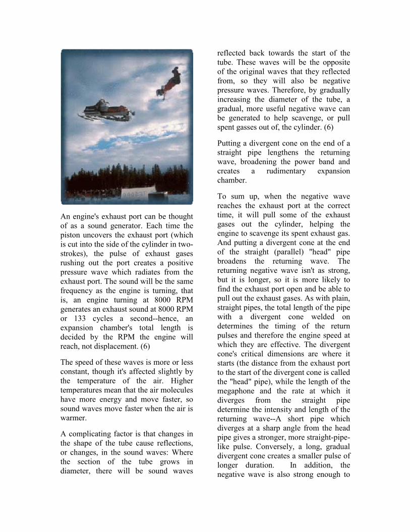
An engine's exhaust port can be thought of as a sound generator. Each time the piston uncovers the exhaust port (which is cut into the side of the cylinder in two-strokes), the pulse of exhaust gases rushing out the port creates a positive pressure wave which radiates from the exhaust port. The sound will be the same frequency as the engine is turning, that is, an engine turning at 8000 RPM generates an exhaust sound at 8000 RPM or 133 cycles a second--hence, an expansion chamber's total length is decided by the RPM the engine will reach, not displacement. (6)
The speed of these waves is more or less constant, though it's affected slightly by the temperature of the air. Higher temperatures mean that the air molecules have more energy and move faster, so sound waves move faster when the air is warmer.
A complicating factor is that changes in the shape of the tube cause reflections, or changes, in the sound waves: Where the section of the tube grows in diameter, there will be sound waves
reflected back towards the start of the tube. These waves will be the opposite of the original waves that they reflected from, so they will also be negative pressure waves. Therefore, by gradually increasing the diameter of the tube, a gradual, more useful negative wave can be generated to help scavenge, or pull spent gasses out of, the cylinder. (6)
Putting a divergent cone on the end of a straight pipe lengthens the returning wave, broadening the power band and creates a rudimentary expansion chamber.
To sum up, when the negative wave reaches the exhaust port at the correct time, it will pull some of the exhaust gases out the cylinder, helping the engine to scavenge its spent exhaust gas. And putting a divergent cone at the end of the straight (parallel) "head" pipe broadens the returning wave. The returning negative wave isn't as strong, but it is longer, so it is more likely to find the exhaust port open and be able to pull out the exhaust gases. As with plain, straight pipes, the total length of the pipe with a divergent cone welded on determines the timing of the return pulses and therefore the engine speed at which they are effective. The divergent cone's critical dimensions are where it starts (the distance from the exhaust port to the start of the divergent cone is called the "head" pipe), while the length of the megaphone and the rate at which it diverges from the straight pipe determine the intensity and length of the returning wave--A short pipe which diverges at a sharp angle from the head pipe gives a stronger, more straight-pipe-like pulse. Conversely, a long, gradual divergent cone creates a smaller pulse of longer duration. In addition, the negative wave is also strong enough to

help pull fresh mixture up through the transfer ports. (6)
While adding a divergent cone to the head pipe produces great tuning advantages, it has its limitations as well: The broader negative wave from a megaphone can still arrive too early and pull fresh mixture out of the cylinder. However, putting another cone, reversed to be convergent, on the end of the first divergent pipe will reflect positive waves back up the pipe. These positive waves will follow the negative waves back to the exhaust port, and if properly timed will stuff the fresh mixture that was pulled into the pipe back into the exhaust port right as the piston closes the port. (6)
In addition to head pipe length, divergent and convergent cone lengths, an expansion chamber has three more crucial dimensions. The length of the straight 'belly' between the divergent and the convergent cones, the length of the tailpiece 'stinger' and the diameter of the belly section. The stinger acts as a pressure bleed, allowing pressure to escape from the pipe. Back pressure in the pipe, caused by a smaller-diameter or longer stinger section, helps the wave action of the pipe, and can increase the engine's performance. This, presumably, happens since the greater pressure creates a more dense, uniform medium for the waves to act on--waves travel better through dense, consistent mediums. For instance, you can hear a train from a long way away by putting you ear to the steel railroad track, which is much denser and more uniform than air. But it also causes the engine to run hotter, usually a very bad characteristic in two-strokes. (6)
The length of the belly section determines the relative timing between the negative and positive waves. The timing of the waves is determined by the length of this characteristically straight pipe. If the belly section is too short, positive waves have a shorter distance to travel, and return to the exhaust port sooner. This is good if the engine is running at a higher speed, bad if you want to ride on the street. The diameter of the belly section is crucial for one simple reason: ground clearance. It's hard to keep big, fat pipes off the ground, though V-Fours have solved that for now since two of the pipes exit directly out the back. (6)
A complete two-stroke pipe has a properly tuned header, convergent, belly, divergent and stinger sections--a difficult process to mesh successfully. Modern pipes generally have a gently divergent head pipe to keep gas velocity
high near the port, a second cone of "medium" divergence, and a third divergent cone with a strong taper. A belly section connects to multi-angled convergent cones, which should exit in a straight line into the stinger for good power. As you can see, modern two-stroke expansion chambers create a complex scenario and are quite difficult to tune.(6) To start with, you need a good design of the chambers you are about to make. This is absolutely the most important thing to get a good result. What a good

design is, obviously depends upon what kind of power you want, what tune you want the rest of the engine have, etc. There are many factors that decide how the chambers should be designed, for example if you raise the exhaust port, you will move the powerband to higher rpm's, and by lengthening the chambers you will move the powerband to lower rpm's. A good chamber will give lots of power over a wide rpm-range. A poorly designed chamber will have a weak pressure wave that won't suck the charge out of the cylinder, and in turn won't push much fresh charge back into the cylinder, producing less horsepower, wasting fuel and increasing pollution.(5) Here are a few examples of possible chamber designs:
or possibly,
THE TUNED PIPE DESIGN PROCESS
As previously stated, expansion chambers are shaped as they are so they reflect sound waves back at the exhaust port to hold the burnable charge in the cylinder. Without the expansion chamber, a large amount of power producing fuel and air would escape from the exhaust port because the exhaust port must be open when the fresh fuel/air charge rushes into the combustion chamber. Four-strokes don't need two stroke type expansion chambers because they have valves that seal their exhaust ports during the intake cycle. Though each section of an expansion chamber has its own areas of influence on power delivery, it is important to point that no section of an expansion chamber works entirely independent of the others. Any change in length, shape or volume in any part of the pipe will bring about changes in the way the pipe affects performance. Generally, changes that hurt performance in one area will boost performance in another, but it is possible to make changes that only hurt or help performance.(4)

EXPANSION CHAMBER COMPONENTS
HEADPIPE: Tapered head pipes are relatively more difficult and costly to manufacture, so they are rare on non-race machines. Tapered head pipes have proven to boost performance and ease pipe tuning in their main area of influence � low to mid rpm power � which has proven to be best for most racing applications. In general, a relatively longer head pipe will bring about more bottom-end power at the expense of peak power. A short head pipe generally brings on stronger peak power and subtracts bottom-end. CONES: The length, volume and taper of the first cone strongly influence the amount of peak power the engine will produce. A relatively short, steeply tapered, first cone, creates high peak power with sacrifices at other engine speeds. Pipes on Open-class bikes usually have gradually tapered first cones because smoothness, rather than peak power, is of more benefit. BELLY: A pipe's midsection is where length or volume adjustments are made to compensate for less than "ideal" head pipe, first cone, final cone and stinger/silencer dimensions that can't be used due to the size and shape of the bike or snowmobile. The pipe's midsection or "belly" can be enlarged, shortened or lengthened to bring about the same results as most "ideal" designs. FINAL CONE: What happens after an engine's power peaks is nearly as important as the peak itself. Controlling power after the peak, the overrev or overrun is the final cone's job. A relatively longer, gently tapered final
cone will give you more overrev. A short, steep final cone gives you less. Why not go for lots of overrev? You will lose too much top-end. It's pretty much all give and take � that�s where the engineering comes in. STINGER: The tailpipe, or stinger, is as important as any part of the pipe. Its size and length influences peak power and bottom-end, and can even affect an engine's resistance to holing pistons. In general, smaller stinger diameters create more peak horsepower but increase the likelihood of melted pistons because they bottle up the exhaust heat. Big stinger diameters boost bottom-end at the expense of peak power. Excessively large stinger diameters can hurt performance at all engine speeds due to insufficient back pressure. Stingers length is important, too, because it's part of the total pipe length and volume. Generally, longer stingers help low and midrange power. Why not run a long, large diameter stinger? The pipe has to fit on the bike.(4)
EXHAUST TUNING THEORY The two-stroke engine can be considered �atmospheric� when the cylinder filling (scavenging) is superimposed to the exhaust phase, i.e., with the exhaust port opened to the external atmosphere. The effectiveness of the cylinder filling with fresh charge depends on small differences of pressure, and the two-stroke engine can only tolerate small amounts of exhaust back pressure. In SI engines, which use the crankcase as a scavenging pump, the dynamic effect plays a fundamental role in filling the cylinder with fresh charge. As

explained earlier, every time the exhaust flow meets a section increase, a negative pressure is generated and propagates in the opposite direction of flow with the speed of sound. On the other hand, if the flow finds a restricted section, a positive pressure wave always propagates in the opposite direction with the speed of sound. (8) According to acoustic theory, the propagation of waves depends strictly on the length and section of ducts, volumes, and logically on the speed of sound. Therefore, the exact tuning for the required boost effect is possible only for a particular range which is usually at the BMEP condition (brake mean effective pressure). A tradeoff between maximum obtainable BMEP and range width is possible, and different solutions can be used, depending on the required engine output. One parameter is fundamental: the propagation of sonic speed waves. The speed of sound depends on several parameters, however if the medium in which the sound wave propagates is the same, the most important term is the absolute temperature as follows: a = √kRT or approximately a = 20√T (m/sec) Predicting exhaust gas temperature is difficult because an exact calculation must be taken into account which includes the heat transmission from the exhaust system to the ambient and the operating air-fuel ratio of the engine. In Figure 1 below, the reference temperature into the exhaust system is reported versus engine maximum power RPM, and thus a zone corresponding to
the specific output of the appropriate engine can be defined to assist with empirical data.
Figure 1 (8)
SHARP RANGE TUNING With high-performance engines, such as snowmobiles, the maximum tuning effects need to be obtained. Therefore, the dynamic effect of compression and expansion waves must be carefully managed. In this case, calculations can be performed following a method of solving the differential equations representing the physics of the actual engine. Sometimes, an empirical technique can be used to quickly check the geometrical dimensions. Using Figure 2 below with the following labels, we start with:

Figure 2 S = Total exhaust angle (CA deg) T = Total scavenge angle (CA deg) D1 = Exhaust duct internal diameter (m) N = tuning (RPM) A negative reflection is requested after (S-T)/2 = A (CA deg) The time for the reflection is tr = A/6N The value of the sonic speed can be estimated, if the temperature inside the muffler is known, as c1 = 20√T1 (m/sec) where T1 is the absolute temperature in ºK. Thus, 2Lcol = c1 tr
Lcol = c1 tr /2 Divergent Part (angle 8º) D2 = √(6(D1
2)) Ld = (D2 � D1)/ tg 4º Convergent Part (angle 15º) A positive reflection (compression wave) is needed afterward
A + T = B (CA deg) With similar considerations, using a new value for c2 if the temperature is changed (C2 = 20√(T2): tc = B / 6N Ltot = c2tc / 2 Lc = (D2 � Du) / 2 tg 7.5º Lct = D2 / 2 tg 7.5º Ltot = Lcol + Ld + Lcil +Lct / 2 + s Thus the length of the cylindrical part can be derived as: Lcil = Ltot � s � Lcol � Ld � Lct / 2 The tail has an approximate length of Ltail = 12Du
*************************(8)
ENGINE MODELING AND SIMULATION TECHNIQUES
One-Dimensional Methods
The purpose of 1-D methods is to calculate the response of the different parts of the engine- namely, the inlet, crankcase, scavenge and exhaust ducts, and muffler � to determine, by using calculations on the entire flow through the engine, the predicted performance and the final value of different parameters such as charging efficiency, short-circuit ratio, and noise pressure levels. Usually this method consists of splitting the engine into several smaller
parts that then can be schematized with ducts of different sections and lengths and connecting volumes.
The basic equations can include heat transfer and friction in the ducts, but obviously can�t take into account the turbulence effect in any part of the engine. These methods have the advantage of a rapid response on overall engine performance, making it easy to compare the influence on engine output of different geometrical configurations. The general drawback lies in the fact that accurate external calibrations, derived from experimental tests, are necessary, and then it�s important to have a solid knowledge of the physical behavior of every engine family. The valid use is only to obtain comparative results for a well-defined class of engines.
Many methods have been developed for solving differential equations. These range from the �characteristic method�, which could also be solved graphically, to modern numerical methods made possible only by the advent of computers. One of the most effective known methods, particularly dedicated to the two-stroke engine, is the �Two-Stroke Simulation Program� developed by Queen�s University of Belfast (QUB). This method includes friction, heat transfer, and multiple ducts, as well as catalyst insertion and multi-cylinder capabilities.
The 3 conservation equations are: continuity, momentum (without friction), and constant entropy.
The continuity equation is
txu ∂−∂=∂∂ //)( ρρ
The momentum equation is
DtDux // ∂=∂∂− ρ
Where Du/Dt is the substantive derivative of velocity with respect to time.
xuutuDtDu ∂∂+∂∂= ///
The expansion of the continuity and momentum equations, respectively, yields
xuutuxp
andxuutp
∂∂+∂∂+∂∂
=∂∂++∂∂∂
//)/(/1
0//)/(/1
ρ
ρ
The sonic speed at the pressure p and density ρ and entropy is given by
spa )/(2 ρ∂∂=
for an ideal gas
)/(2 ρkpa =
The 3rd conservation condition (isentropic flow) is
)1/(2)/(/ += kkAref aapp
when pref and aA are reference values.
After substitution, the continuity equation can be expressed in terms of a and u as
0///)1/(2 =∂∂+∂∂+∂∂− xuutuuaak
and the momentum equation can be expressed as
0///)1/(2 =∂∂+∂∂+∂∂− xuutuuaak

After some lengthy manipulation of these equations, the following equation can be obtained:
da/dt + (k-1) / 2du / dt = 0 (*)
on a line on the x-t field (where x is the current abscissa) whose slope is
dx / dt = u + a
and
da /dt – (k-1) = 2du /dt (#)
on a line whose slope is dx /dt = u -a
To generalize the results, it�s useful to write the equations in non-dimensional form, introducing
A = a/aA; U = u/aA; X = x/L; and Z = aAt/L
As Riemann variables.
Consider the line of slope dX/dZ = U+A shown in the Figure 3.
Figure 3
This is known as a �position characteristic� and is seen to be in the direction of a disturbance propagating toward the right through the gas in the pipe.
Integrating EQN (*)
A + (k-1) / 2U = constant = λ
The constant λ exists at any point along the position characteristic. A and U can vary only along a position characteristic within the restraint imposed by the relation in this equation.
Therefore, if the properties of the initial disturbances are known, a family of λ lines can be drawn, shown in Figure 4.
Figure 4
Disturbances moving toward the left will propagate along a line of slope dX/dZ = U �A. Similarly, EQN(#) above gives:
A – (k-1) / 2U = constant = β

The value of β is derived from the initial values of A and U. These lines are also shown in Figure 3.
The terms β and λ are known as Riemann variables. The particle velocities and fluid properties can be found at any point of the X-Z plane:
(1+b)/2 = A = a/aA
(1-b)/2 = U = u/aA
Because
a/aA=(p/pref)(k-1)/2k
That is,
((1+b)/2)2k/(k-1) = p/pref
((1+b)/2)2 = T/Tref
((1+b)/2)2/(k-1) = r/rref
The results for the last 6 equations can be used to produce a numerical solution to problems of unsteady flow. Obviously, the real problem is more complicated, i.e., the duct may have a variable or a sonic shock wave may be generated.
Two-Dimensional Methods
Theoretical three-zone model for loop-scavenge engines:
The mathematical model consists of five conservation laws in somewhat 3-D form:
0/))/((
/))/((/)(/)(/)(
=+∂∂∂Γ∂
−∂∂∂Γ∂−∂∂+∂∂+∂∂
ψψ
ψ
ψψ
ρψρψρψ
Syxxx
yuxut
Any of the five equations can be derived, where the symbols have the following significance:
x and y designate the Cartesian coordinates of a Eulerian frame
Ψ is the general transport property
ΓΨ is the transport coefficient
SΨ is the source term
u and v are the velocity components in the x and y directions
t designates the time
ρ is the density
µ is the viscosity
k designates the thermal conductivity
cp is the heat capacity
h is the specific stagnation enthalpy
p is the pressure
Dab is the mass diffusion coefficient
X designates the mass fraction of the fresh charge
The differential equations must be modified to allow the domain of the solution to be always within the boundary of the volume occupied by its gas with a coordinated transformation.
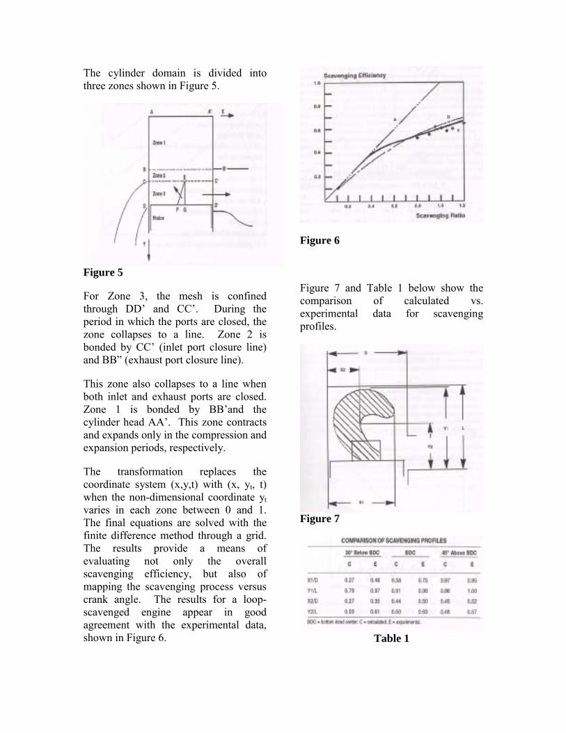
The cylinder domain is divided into three zones shown in Figure 5.
Figure 5
For Zone 3, the mesh is confined through DD� and CC�. During the period in which the ports are closed, the zone collapses to a line. Zone 2 is bonded by CC� (inlet port closure line) and BB� (exhaust port closure line).
This zone also collapses to a line when both inlet and exhaust ports are closed. Zone 1 is bonded by BB�and the cylinder head AA�. This zone contracts and expands only in the compression and expansion periods, respectively.
The transformation replaces the coordinate system (x,y,t) with (x, yt, t) when the non-dimensional coordinate yt varies in each zone between 0 and 1. The final equations are solved with the finite difference method through a grid. The results provide a means of evaluating not only the overall scavenging efficiency, but also of mapping the scavenging process versus crank angle. The results for a loop-scavenged engine appear in good agreement with the experimental data, shown in Figure 6.
Figure 6
Figure 7 and Table 1 below show the comparison of calculated vs. experimental data for scavenging profiles.
Figure 7
Table 1

Three-Dimensional Methods
KIVA is the most recent of a long series of fluid-dynamics codes devoted to the study of engine applications and developed at Los Alamos National Laboratory since the early 1970�s.
KIVA solves the transient 2-D and 3-D chemically reactive fluid flows with sprays. It is applicable to laminar or turbulent flows, subsonic or supersonic, and single-phase or two-phase flows. The gas phase solution procedure is based on a finite volume method called the Arbitrary Lagrangian-Eulerian (ALE) method. The grid is a single block structure. KIVA can simulate two-stroke engines, allowing connecting and disconnecting of port volumes with in-cylinder volume. This is performed automatically, also controlling the time-step when opening of the ports results in a sudden (sonic) acceleration of the flow. To move the piston from its top dead center position to bottom dead center position and back again, a special piston motion logic has been devised. The logic is called �snapper.� As shown in Figure 8, the lowest plane of active cylinder coincides with the piston crown and with the piston velocity.
Figure 8
All other vertices remain stationary. Periodically, however, a new plane of piston crown vertices replaces the old one and assumes its role of following the piston motion. The old plane of piston vertices is �snapped� back to its original position, which is now below the piston crown, and a simple remap onto the new mesh (redefining cells, vertex, and flags) is performed. When the piston is moving downward, the procedure is reversed. The experimental results derived from a loop-scavenged two-stroke engine show very good agreement with predicted velocity field and a coherent evaluation of two-stroke characteristic parameters.
(8)

EMISSIONS BASIC PRINCIPLES The main source of the generation of unburned hydrocarbon emissions in SI (spark ignition) engines is caused by the short-circuit of the fresh mixture through the exhaust port during the scavenging phase. The meaning of the short-circuit is that part of the incoming fresh mixture after the inlet in the cylinder is short-circuited directly through the exhaust port. Although the emissions of carbon monoxide (CO) and nitrogen oxides (NOx) depend mainly on the combustion characteristics, unburned hydrocarbon (HC) emissions in SI engines are caused by this short-circuit of fresh mixture through the exhaust port.(8) BASIC SOLUTION One of the methods used in production to reduce hydrocarbon and CO emissions is air injection into the exhaust system. Oxides of nitrogen will not necessarily be reduced; in fact they may be increased if sufficiently high exhaust temperature results from the combustion of the CO and hydrocarbons with the added air or if the injected air enters the cylinder during the overlap period, thereby leaning the mixture in the cylinder. To achieve a high degree of exhaust system oxidation of HC and CO, a high exhaust temperature coupled with sufficient O2 and residence time to complete the combustion is needed. If a flame is established, the heat generated by the combustion of the CO and hydrocarbons keeps the reaction going.(7) Because of its abundance, the carbon monoxide in the exhaust provides most
of the combustion-generated heat. The basic factors governing the combustion of CO and HC in the exhaust system are: composition of the reacting mixture, temperature and pressure of the mixture, and residence time of the mixture or time available for reaction.(7) General laboratory testing has shown that the minimum HC concentrations occurred at rich mixtures. When too much air was injected, especially at lean mixtures, excessive cooling of the exhaust increased HC concentrations to levels above those with no air. Thus, the normal oxidation process was apparently inhibited by this cooling. The effect of air injection on CO concentrations was somewhat different. Exhaust CO was uniformly low at most rich-air-fuel ratios. A small increase in CO occurred slightly richer than stoichiometric. At stoichiometric and leaner, CO was very low. The leanest air-fuel ratio for best emission reduction was 13.5:1. Normally, engine operation at such a rich mixture would reduce fuel economy by 10%. The very low emissions with rich mixtures and air injection arose from a �fire� in the exhaust system. For mixtures leaner than the small CO peak in Figure 9, non-luminous oxidation occurred and CO emission reduction was relatively poor.
Figure 9 (7)

OPTIMIZATION OF AIR INJECTION RATE At each air-fuel ratio there exists one minimum air injection rate that provides maximum emission reduction. Minimum air flow is desired in order to reduce pump power requirement, size and cost. Air injection is not highly effective in reducing CO emission unless a luminous burning flame occurs.(7) EXHAUST TEMPERATURE AND PRESSURE Exhaust system insulation is necessary to achieve high reaction rates in engines with well-cooled exhaust ports. Insulation also helps to reduce emissions during warm-up by accelerating the warm-up rate. At mixtures significantly leaner than stoichiometric (in the range of 16 to 17.5:1) air injection is not needed to supply O2; in fact it would only cool the exhaust to too low a temperature for any reaction to occur. On the other hand, at such lean mixtures only extremely good heat conservation can produce temperatures high enough for appreciable reaction. For lean mixtures, the following equation for the concentration of hydrocarbons leaving the exhaust system was derived:
whereWTK
VPOKCC ri
−= 2
3
22
0 exp
Co = conc. of HC leaving exhaust system Ci = conc. of HC leaving cylinders and entering exhaust system
Kr = specific reaction rate, ft3/lbm*mole/sec K3 = constant
O2 = oxygen concentration in exhaust gases, volume % P = exhaust pressure (psia) V = exhaust system volume available for reaction, ft3 T = absolute temperature, °R W = mass flow rate of air, lb/sec. Note the importance of the pressure term. Increasing exhaust back pressure promotes after-reaction. However, commercially, the possible back pressure increase is small. General laboratory results show that a decrease in exhaust temperatures from 1100°F to 1000°F decreases the reaction rate by a factor of 10 � Something to think about.(7) EXHAUST SYSTEM VOLUME-RESIDENCE TIME EFFECTS Reactor volume may be viewed as the volume of the exhaust system which is insulated and at the high temperature needed for reaction. General laboratory testing shows that if the exhaust temperature were at 1400°F (Ski-Doo specs show 1330°F), only twice the convention system volume is required for virtually complete elimination of the hydrocarbons. On the other hand, if the temperature were only 1200°F, eight times the volume would achieve only a 76% reduction. Increasing the exhaust system volume increases the residence time during which reactions can occur. This will be a benefit only if the added surface area does not result in excessive cooling. Thus, when large volume exhaust manifolds are used, they must be well insulated. In conclusion, increasing the residence time of the exhaust by

increasing volume improves both the CO and HC oxidation effectiveness of air injection and reduces the injected air flow requirement provided that good heat conservation is maintained. Note: this applies to both rich and lean fuel mixtures. The most effective reactors are those that run rich with air injection. Rich engine operation produces low NO and high CO and H2 emissions. Vehicle experience shows that combustion of the CO and H2 with the injection air generates temperatures high enough to oxidize virtually all the unburned hydrocarbons.(7) Table 2 below shows the stock exhaust emission values taken with the engine idling at 129°F.
HC CO CO2 O2 NOx 5690ppm 1.81% 3.7% 0 14.1%
Table 2
OUR DESIGN PROCESS
When Jay, Brian and I initially started the design process, we planned on quickly �throwing� together a pipe and then being able to focus the majority of our attention on decreasing harmful emissions. NOT EVEN CLOSE. First
and foremost, we realized the need to have more than just a general idea of two-stroke engine operation in order to understand exactly where these so-called emissions were coming from. During the process of engine research, we quickly found just how much of an effect the exhaust system has on optimal operation of the two-stroke engine: a huge one. This realization immediately altered our design project to something of much larger scale than we had originally anticipated. Now we had to first successfully design a high performance pipe for this two-stroke snowmobile (obviously no easy task in itself) with emissions still in mind of course, and then deal with the emissions issues. So� We decided to look for suitable two-stroke engine simulation software where we would be able to take engine and exhaust characteristic values of the Ski-Doo sled and plug them into the program, generating values we had already achieved on the Dyno (values of horsepower, rpm etc). This would give us a baseline where we would simply be able to change the dimensions of the exhaust (within the simulation program) and see how it affected our engine performance, therefore allowing us to optimize the design by changing values accordingly. Didn�t happen. Below is a table of the current engine values. Feature Dimensions/RatiosBore 69.5mm Stroke 61mm Total Displacement 462.8cc Con rod length 130mm Crankcase Compression ratio
1.55
Squish Clearance .58mm Wrist pin-to-crown 25 Wrist pin-to-skirt 25 Wrist pin offset 0

Fly wheel diameter 243mm No. of exhaust ports 1 Top corner radius 10mm Bottom corner radius 10 No. of transfer ports 5 Ave max. width 19mm Top corner radius 6.8mm Bottom corner radius 6.8mm Fuel type Gasoline Air : Fuel ratio 13.5 Table 3 – Note: Values are metric for compatibility w/ software We found a simulation program by Gordon Blair (see Proff. Mick Peterson for instruction manual) and it was disastrous. It is not user friendly, requires much more engine characteristic values than other simulation software on the market, is written to simulate a single cylinder GP motorcycle, and incorporates the use of a reed valve (which the sled does not have). Most of these details were not apparent by reading the available literature. We worked around the �single cylinder� issue by doubling the rpm�s, but when trying to deal with the reed valve, or lack thereof, we hit a wall. You can�t just set the reed valve values to zero or it throws the entire program off. Not only was it useless, more importantly, we wasted valuable time. At this point we�d already flushed $500 of the University�s money down the toilet on inapplicable software, so new software was out of the question. But if you want make an omlet, you gotta break a few eggs, right? The only thing left to do was establish the stock exhaust temperature gradient using thermocouples and Daqbook, then design the new exhaust empirically (hand calcs and 1,2,3,-Dimensional analysis as shown above and in lab notebook), fine-tuning with a trial-and-error process. We already had stock
horsepower, torque vs. rpm curves (Appendix A), as well as temperature profiles (Appendix C) so we could calculate lengths and diameters from earlier equations and estimate sizes based upon where we wanted to see improvements made.
GETTING STARTED
Because a long, gradual divergent cone creates a smaller pulse of longer duration, we manipulated the calculations to allow for a divergent cone that was longer and more gradual than the existing one. This alteration also strengthens the negative wave enough to help pull fresh mixture through the engine transfer ports. This is how we were able to reach maximum horsepower shortly after the track was engaged. As stated above, if the belly section is too short, positive waves have a shorter distance to travel, and return to the exhaust port sooner. This is good if the engine is running at a higher speed, bad if you want to ride on the street. Because a snowmobile operates at such high rpm�s, this is the type of design we went after. Our first test pipe had a belly length approximately 3� longer than the stock belly. We started longer because a pipe's midsection is where length or volume adjustments are made to compensate for less than "ideal" head pipe, first cone, final cone and stinger/silencer dimensions that can't be used due to the size and shape of the sled. The pipe's midsection or "belly" can be enlarged, shortened or lengthened to bring about the same results as most "ideal" designs. It�s much easier to change a length, cut and weld, than it is

to change multiple lengths and diameters. Our convergent (final) cone was made shorter and steeper than the stock exhaust to give less overrev, in turn preserving top-end. Top-end is crucial to successful snowmobile operation. A stinger similar to stock diameter was used to sustain sufficient back pressure to maintain the wave action of the pipe, and hopefully maintain the engine's performance. Because smaller stinger diameters deliver more peak horsepower, but also increase the likelihood of melted pistons (because of bottling up the exhaust heat), we opted to use an approximate stock diameter and adjust the belly length to increase performance. A larger stinger diameter was out of the question because it may boost bottom end, but only at the expense of peak power. Stinger length is also important to help low and midrange power. This is why we made ours longer than stock�it worked. Below in Table 4 and Figure 10 you can see the dimensions of our first prototype.
L1 L2
D1 D2 D2
7.13°
Head Pipe
Head Pipe Convergent Cone and stinger
Divergent Cone & Belly
Divergent Cone &Belly
L3 L4
D2
D3
8°
Figure(s) 10
D1 2.78� D2 2.39� D3 5.81� Du 1.25� L1 1.575� L2 6.89� L3 12.17� L4 13.54� L5 8.51� L6 15.00�
Table 4
MATERIAL SELECTION We employed carbon steel sheet metal, .0312� thick. The primary reason(s) for the selection of this material are it�s commonplace in the motorcycle industry, it�s ability to be easily welded and it is lighter than the stock exhaust. Stainless steel was found to be more brittle and therefore more susceptible to cracking over repeated seasons of use.
METHOD TO THE MADNESS The SRW Team in Italy was kind enough to email us their Excel file
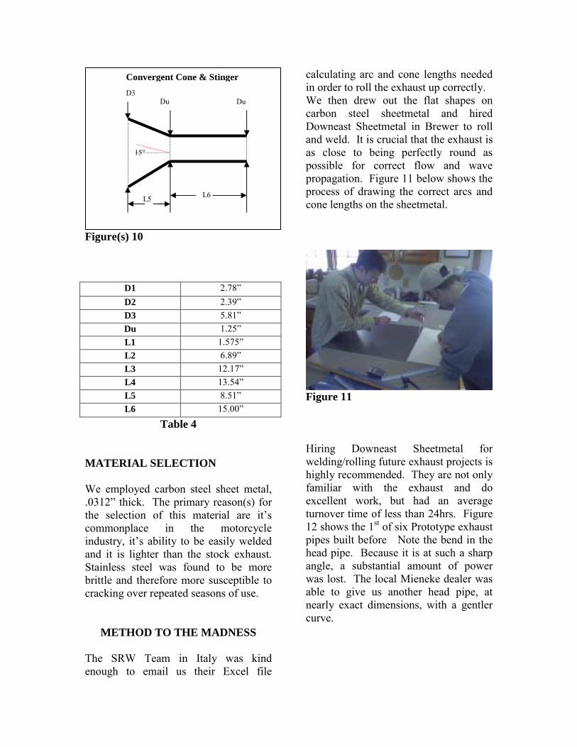
calculating arc and cone lengths needed in order to roll the exhaust up correctly. We then drew out the flat shapes on carbon steel sheetmetal and hired Downeast Sheetmetal in Brewer to roll and weld. It is crucial that the exhaust is as close to being perfectly round as possible for correct flow and wave propagation. Figure 11 below shows the process of drawing the correct arcs and cone lengths on the sheetmetal.
Figure 11 Hiring Downeast Sheetmetal for welding/rolling future exhaust projects is highly recommended. They are not only familiar with the exhaust and do excellent work, but had an average turnover time of less than 24hrs. Figure 12 shows the 1st of six Prototype exhaust pipes built before Note the bend in the head pipe. Because it is at such a sharp angle, a substantial amount of power was lost. The local Mieneke dealer was able to give us another head pipe, at nearly exact dimensions, with a gentler curve.
Convergent Cone & Stinger
L5 L6
D3 Du Du
15°

Figure 12 Shown here in Figure 13 is the Daqbook DBK19 Thermocouple card with type K & E thermocouples connected to it. (Instructions for connection and operation can be seen in Appendix B)
Figure 13 Figures 14 & 15 show the exhaust-end connections for the thermocouples, held in with screws, for the Dynojet testing procedure. This is the apparatus used to record both stock and new exhaust temperature profiles.
Stock Thermocouple Connections
Figure 14
Prototype Thermocouple Connections
Figure 15 When testing either of the exhausts, stock or new, it is important to note that a separate radiator should be hooked to the snowmobile cooling system. This enables sufficient engine cooling while allowing the engine and exhaust gases to heat to normal operating levels. We used a large radiator in a bucket of water or snow during Dynojet testing. Figures 16 and 17 show the set-up.

Figure 16 You can see that the external radiator is simply piped into the snowmobile�s cooling system.
Figure 17 After dynojet testing 6 pipes with belly lengths of 13.54�,11.54�, 9.54�, 8.54�, 7 1/8�,6 1/8�, we found that a 7 1/8� belly provided optimal results. When comparing this particular prototype (5th pipe) with the stock exhaust (Appendix A) we not only exceeded the maximum torque provided by the stock pipe, but also produced virtually identical peak horsepower. More importantly though, we sustained 10 horsepower more (at the track) from ~27mph to 52mph AND hit peak horsepower almost 1000rpm sooner, boosting low-end as well.
Note: All Dyno numbers provided in the Appendix are taken at the track. General experience shows an approximate loss of ½ the horsepower provided by the engine in the track.
Appendix A shows all significant test pipe horsepower/torque curves. Table 5 shows the pipe dimensions for optimal power and torque output (Prototype 5).
D1 2.78� D2 2.39� D3 5.81� Du 1.25� L1 1.575� L2 5.67� L3 12.17� L4 7 1/8� L5 8.51� L6 15.00�
Table 5
ANOTHER PITFALL Once we decided upon which prototype to use, we returned to Downeast Sheetmetal and asked them to �bend it up� so we could put it on the sled. Using a basic Cartesian (X-Y-Z) coordinate system, we provided them with guidelines, dimensions and locations for fabrication. Unfortunately, they soon told us that it was impossible to construct a divergent cone that would swing through the angle necessary to fit under the cowling � for them anyway. We knew there had to be a way to make the needed cone bend correctly, maintaining centerline length and end diameters. We referred back to the SRW race file and incorporated basic trigonometry with occasional estimation. We found the best way to do this was by constructing a cardboard model to be

used as a welding template, shown in Figures 18 and 19.
Figure 18
Figure 19
Once the cardboard model was complete, we made sure it would fit in the area under the cowling (Figure 20) and brought it back to Downeast Sheetmetal to be welded.
Figure 20 The result is shown in Figures 21, 22 and 23.
Figure 21

Figure 22
Figure 23
Now we had to find a way to bend the stinger because there is no company in the greater Bangor area that is able to do it. It�s difficult to find a material that will bend through such a tight angle without splitting or crimping, and local shops had no equipment for the job either.
FABRICATION PROBLEMS
Fortunately, our exhaust pipe design proved better than the Ski-doo pipe, but due to a lack of resources and materials, there was no way to fabricate it correctly. In order to arrive at a stinger that would bend through such a sharp angle, two common, plumbing sink pipes were
welded together (courtesy of Home Depot). Because of area and dimension restrictions the stinger was not welded in a direct line with the convergent cone. As stated above, in order to maintain good power, the convergent cone should exit in a straight line into the stinger. In order for the exhaust pipe to reach the muffler location, the head pipe and the belly were also lengthened by 2� and 1� respectively. Appendix A shows the drastic effects of these design changes upon performance. Note: For future groups picking up where we left off, be sure and use the same convergent and divergent cones and shorten the belly by one inch. The optimal head pipe and stinger dimensions are given in Table 5, so you only have to find away to make them bend correctly. PROPOSED IDEA FOR EMISSIONS
REDUCTION
In theory, if you add the right amount of air to the exhaust gases AND keep this mixture above a certain temperature (through good insulation), it will combust inside the exhaust pipe, burning off the majority of the harmful emissions. In theory. As said above, if too much air is added you will actually cool the exhaust, in turn increasing HC emissions. So if we were going to even come close to making this happen, we wouldn�t be able to just dump cold air anywhere in the exhaust flow. We decided to run 3/8� copper tubing (good heat transfer coefficient) down one side of the exhaust and back up the other (under the
insulating wrap), to then inject (pointing downstream) as close to the headers as possible. This would allow for the air to pre-heat before it was mixed with the hottest exhaust gases possible.
AIR PUMP Finding a suitable air pump is actually a fairly difficult task; the general market is quite limited. In order to withstand the pressure waves created by the exhaust during operation, a linear piston pump (positive displacement) is necessary. The difficulty comes in finding a variable displacement pump as the sled will obviously not be running at constant rpm and therefore, a constant displacement pump would only suffice for a very specific rpm value. The only pump we were able to find that could withstand exhaust pressures was rated for 18psi, 2.5ft3 and 12V. It is not variable displacement and so you can only hope for a small window for combustion (if at all). This air pump accounts for a 2-4% addition to volumetric flow. Either way, even if it doesn�t burn, your emission numbers will still decrease because of dilution. By the way, this is cheating. However, when the air pump was turned on during the dyno runs, the temperature at each point rose 100°F (see Appendix C ) immediately. This proves that the air actually ignited, helping to decrease our harmful emissions.
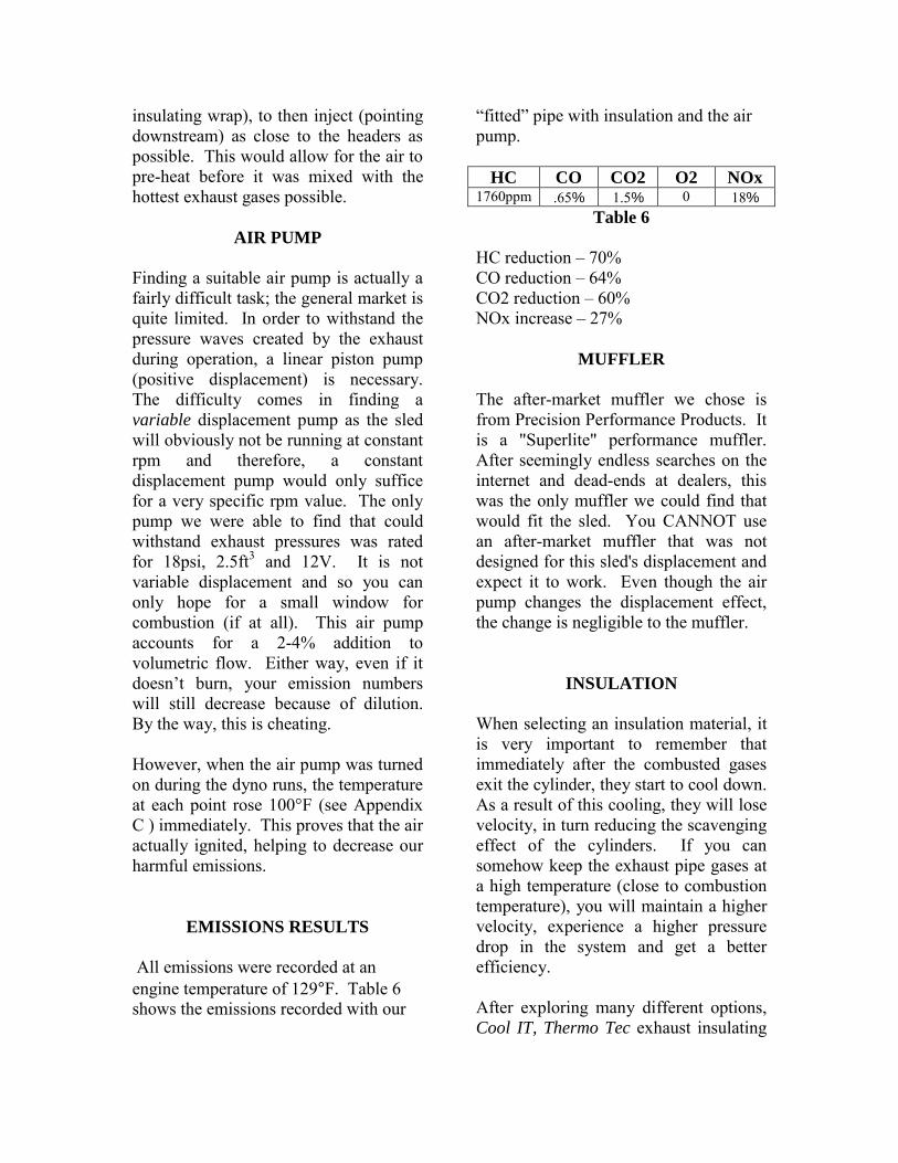
EMISSIONS RESULTS All emissions were recorded at an engine temperature of 129°F. Table 6 shows the emissions recorded with our
�fitted� pipe with insulation and the air pump.
HC CO CO2 O2 NOx 1760ppm .65% 1.5% 0 18%
Table 6 HC reduction � 70% CO reduction � 64% CO2 reduction � 60% NOx increase � 27%
MUFFLER The after-market muffler we chose is from Precision Performance Products. It is a "Superlite" performance muffler. After seemingly endless searches on the internet and dead-ends at dealers, this was the only muffler we could find that would fit the sled. You CANNOT use an after-market muffler that was not designed for this sled's displacement and expect it to work. Even though the air pump changes the displacement effect, the change is negligible to the muffler.
INSULATION When selecting an insulation material, it is very important to remember that immediately after the combusted gases exit the cylinder, they start to cool down. As a result of this cooling, they will lose velocity, in turn reducing the scavenging effect of the cylinders. If you can somehow keep the exhaust pipe gases at a high temperature (close to combustion temperature), you will maintain a higher velocity, experience a higher pressure drop in the system and get a better efficiency. After exploring many different options, Cool IT, Thermo Tec exhaust insulating

wrap appeared to be the best choice for insulation. Thermo Tec Claims: “The exhaust insulating wrap is an innovative way to create more horsepower and reduce underhood temperatures (by as much as 70%). Wrapping headers maintains hotter exhaust gases that exit the system faster through decreased density. Increased exhaust scavenging is produced, along with lower intake temperatures. It withstands continuous heat up to 2000F, and contains no asbestos. Thermo Tec exhaust wrap will not over insulate the system when properly installed due to a proprietary coating that conducts heat across the wrap’s surface. This coating controls heat build-up and dissipation. It is sold with a low profile 1/16” thickness”
CONCLUSIONS & RECOMMENDATIONS FOR
FUTURE WORK As we are sure you can deduce from the given information, two separate exhaust pipes were built: one for optimal power and another to actually fit on the snowmobile. Because of a lack of local resources, we were unable to fit the best pipe to the sled. Hopefully, future groups will find a way around this problem. The air pump increased volumetric flow by 4% on the optimal pipe design and approximately 2.5% to the �fitted� pipe, so the air should ignite using the optimal pipe dimensions as well. Use of an air pump that gets you closer to a stoichiometric reaction may also allow you to further reduce hydrocarbons. Beware of NOx though!!! As said earlier, nitrogen oxides may be increased if you boost the exhaust temperature from the combustion of CO and HC or if the added air enters the
cylinder during the overlap period when both the intake and exhaust are open, in turn leaning the mixture. The belly (of the pipe currently on the sled) should be shortened by exactly 1� while the convergent and divergent cones should not be change at all. Refer to Table 5 for all other dimensions. Temperature profiles and data were taken for both calculation purposes, as well as finding whether or not the injected air was ignited.

Appendix A
DynoJet Performance Results:
Horsepower & Torque Graphs for Stock Pipe & Exhaust Prototypes

Stock exhaust compared with 1st and 2nd Prototype
3rd Prototype compared to Stock

4th Prototype compared with Stock pipe (RPMs)
4th Prototype compared with Stock pipe (MPH)

5th Prototype compared with Stock pipe (RPMs)
5th Prototype compared with Stock pipe (MPH)

6th Prototype compared with Stock pipe (MPH)
6th Prototype compared with Stock pipe (RPMs)

Final Pipe With muffler
Final Pipe with muffler & insulation

Final pipe with muffler, insulation and air pump
Comparison of power for the stock pipe, ideal prototype and final pipe

Comparison of Torque for the stock pipe, ideal prototype and final pipe

Appendix B
Data Acquisition using Daqbook 100s with DBK-19 thermocouple cards and
specifications


DBK Thermocouple Card Specifications


Appendix C Temperature Profiles for Snowmobile
Exhaust
Figure 1 shows the temperature profile for the stock snowmobile exhaust. Point 1 is located at the header. Point 9 is located at the muffler. Point 7 is missing because the thermocouple was damaged.
Figure 1
Temperature Profile for Stock Exhaust Pipe
0.00E+00
5.00E+01
1.00E+02
1.50E+02
2.00E+02
2.50E+02
3.00E+02
3.50E+02
4.00E+02
4.50E+02
5.00E+02
0.00E+00 1.00E+00 2.00E+00 3.00E+00 4.00E+00 5.00E+00 6.00E+00 7.00E+00
Time (seconds)
Tem
pera
ture
(F)
Point 1Point 2Point 3Point 4Point 5Point 6Point 8Point 9
1
2
3 4 5 6
89
Thermocouple Locations

Figure 2 shows the temperature profile for the first prototype exhaust with a sharp 60 degree angle at the head pipe.
Figure 2
Temperature Profile for First Prototype
0.00E+00
5.00E+01
1.00E+02
1.50E+02
2.00E+02
2.50E+02
3.00E+02
3.50E+02
4.00E+02
4.50E+02
5.00E+02
0.00E+00 1.00E+00 2.00E+00 3.00E+00 4.00E+00 5.00E+00 6.00E+00 7.00E+00
Time (seconds)
Tem
pera
ture
(F)
Point 1Point 2Point 3Point 4Point 5Point 6Point 8Point 9

Figure 3 shows the temperature profile for the second prototype exhaust with a rounded 60 degree angle at the head pipe.
Figure 3
Temperature Profile for Second Prototype
0.00E+00
1.00E+02
2.00E+02
3.00E+02
4.00E+02
5.00E+02
6.00E+02
0.00E+00 1.00E+00 2.00E+00 3.00E+00 4.00E+00 5.00E+00 6.00E+00 7.00E+00
Time (seconds)
Tem
pera
ture
(F)
Point 1Point 2Point 3Point 4Point 5Point 6Point 8Point 9
Table 1 shows the temperatures of the final fitted pipe with and without the air pump operating. Temperatures were only taken at the two most important points, the head pipe and the muffler. The dramatic increase in temperature with the air pump operating shows the effects of burning more hydrocarbons before they are exhausted to the atmosphere.
Table 1
Without Air Pump With Air Pump
Head Pipe 499 F 601 F Muffler 277 F 389 F

Bibliography
(1) How 2-Stroke Engines Work - Marshall Bain (2) The Tuned Exhaust System - Adrian Teo, 1996 (3) Basic 2-Stroke tuning � Eric Gorr (4) Exhaust Pipe Theory � Stephen Jordan (5) Building Your Own Expansion Chambers � Skalman
Racing (6) How 2-Stroke Engines Work, & Why You should Care �
Eric Murray (7) Emissions From Combustion Engines & Their Control-
Patterson & Henein (8) Emissions From 2-Stroke Engines � Marco Nuti, 1998