advanced test equipment rentals - atecorp.com · advanced test equipment rentals ... level...
TRANSCRIPT

June 1999
THANK YOU FOR ORDERING A FIREBERD6000 COMMUNICATIONS ANALYZER!
50-16453-01, Rev. C
Revision T.x Software
Please Read This Information
Options
If you have ordered one or more of the FIREBERD 6000's internally installed options, each will appear as a separateline item on your packing slip. To verify that these options have been included in your order, please check the rearpanel of your FIREBERD -- a sticker that lists your instrument's installed options is attached on the lower left cornerof the unit.
Manuals
Your FIREBERD 6000 Communications Analyzer comes with the following documents:
Use This Manual:
To:
FIREBERD 6000 Reference Manual
Obtain a complete description of the FIREBERD, including procedures(50-12120-01, Rev. L)
for getting started with your new instrument.
FIREBERD 6000 Reference Manual
Incorporate the High Speed TTL Interface Module Upgrade, andAddendum (50-14956-01, Rev. F)
FIREBERD 6000 Rev. T .x software. This addendum is valid for Rev. L ofthe FIREBERD 6000 Reference Manual.
Thanks again for choosing a FIREBERD. If you need additional information about how your order was packed,please write or call:
Copyright ®1998 ITC©20400 Observation Drive, Germantown, Maryland 20876-4023 USAUSA 1-800-638-2049 • +1-301-353-1550 (MD) • FAX +1-301-353-0234
Canada 1-888-689-2165 • +1905-507-4117 a FAX +1-905-507-4126www.ttc.com
Advanced Test Equipment Rentalswww.atecorp.com 800-404-ATEC (2832)
®
Established 1981

FIREBERD 6000 REFERENCE MANUAL
June 1999
ADDENDUM50-14956-01 Rev. F
I NTRODUCTION
This addendum incorporates changes into the Revision L FIREBERD 6000 Reference Manual, 50-12120-01, for Revisions P, P2, R, R.1, S, and T FIREBERD 6000 software. Revision P2 provides inverse ARPcapability to the FIREBERD 6000 Frame Relay Option. Revision R provides functionality for the 2M/34MATM Data Interface Module (Model 31650). Revision R.1 includes Frame Relay capability for the HighSpeed Serial Interface Module (Model 42219A). Revision S includes BERT capability for the 34M InterfaceModule (Model 31812). Revision T includes support for the High Speed TTL Interface Module (Model31910), unit now recognizes leap years, and updates T1.403 loop codes to 1995 specifications.
FRONT MATTER
Make the following changes to the front matter of the reference manual.
Change the Software Level to T in the upper right corner, change the date in the middle of the page tothe date the changes are made to the manual; and change the revision level to Rev. T. Change theSoftware Revision level statement to "Software Revision T".
SECTION 2 INSTRUMENT DESCRIPTION
Make the following changes to Section 2, Instrument Description.
Pages 2-68 through 2-71, Table 2-2 Status-Select Auxiliary Functions:
Add the following note to Receiver Action On Synchronization Loss (AUX 03) after the CONTparagraph:This auxiliary function does not apply to results made available by the Frame Relay Option.
Add the following note to Single Transmit (AUX 04) after the disabled in self-loop mode paragraph:When the Frame Relay Option is enabled, one frame will be transmitted each time RESTART is pressed.
Add the following note to Out-of-Band Flow Control (AUX 08), In-Band Flow Control (AUX 09), andSync Loss Threshold (AUX 10): This auxiliary function is not available when Frame Relay is enabled.
Add the following note to Block Length (AUX 30): This auxiliary function is not applicable to FrameRelay operation.
Add the following note to Signal Delay (AUX 31): Start and stop parameters that reference patterns arenot valid when Frame Relay is enabled.
Page 2-105 replace the first step of the Frequency Deviation Stress Test with the following: Set GENCLK to SYNTH.

FIREBERD 600 0 REFERENCE MANUAL ADDENDUM
SECTION 4 REMOTE CONTROL
Make the following changes to Section 4, Remote Control.
Page 4-6, please replace the IEEE-488 Interface DIP switch settings with the following: SW4:16,SW5:8, SW6:4, SW7:2 and SW8:1.
Page 4-74, please replace the RESULT-HOLD[ONIOFF] remote control command with the following:RESULT HOLD. The onloff extensions are not required. The previous results in the buffer areoverwritten by the current results whenever this command is invoked.
Page 4-95, Figure 4-5 Line Summary Register Group:
Replace Figure 4-5 with the following:
Figure 1. Figure 4-5 Line Summary Register Group
Page 4-96, The Line Loss Register Subsection:
Replace the definition of Bit 5 with the following: "Rx Overrun. " This indicates the frame relay optionreceiver has overflowed since this register was last read.
Replace the definition of Bit 4 with the following: "Tx Underrun. " This indicates the frame relay optionreceiver has underflowed since this register was last read.
a
Page 2 of 24

FIREBERD 6000 REFERENCE MANUAL ADDENDUM
SECTION 5 OPTIONS AND ACCESSORIES
Make the following change to Section 5, Options and Accessories:
On page 5-11, replace the description of cable, Model 40601 with the following: Bantam plug (dual) toRJ48C (10').
APPENDIX F
Replace entire Appendix F with the attached pages.

FIREBERD 6000 REFERENCE MANUAL ADDENDUM
F1. OVERVIEW
Page 4 of 24
Frame CountFramed Octet CountErrored Frame CountAborted Frame CountFrames with the FECN Bit SetFrames with the BECN Bit SetFrames with the DE Bit SetAverage UtilizationMaximum UtilizationAverage ThroughputMaximum Throughput
Frame SizeThroughputTransmission Pattern (Constant or Bursty)
APPENDIX F FRAME RELAY
Frame relay is a packet-mode service with high throughput and low delay characteristics. Unlike otherpacket switching technologies, frame relay completely eliminates all processing at Layer 3 (Network Layer)of the OSI Reference Model and performs only a portion of the traditional Layer 2 (Data Link Layer). Sinceframe relay has no error correction capabilities, it must be implemented in relatively error-free networks toensure high throughput.
The Frame Relay option is supported in FIREBERD 6000 equipped with Rev. K software and higher. Theoption allows you to perform Physical Layer analysis of the network by verifying the circuit is able tosupport frame relay operation.
The Frame Relay option provides the ability to collect basic protocol statistics about the frame relay circuitunder test. These protocol statistics include:
These statistics can be collected on one specific DLCI or on the aggregate of all DLCIs.
With the Frame Relay option installed and the 12 FRAME RELAY Auxiliary Function enabled, theFIREBERD 6000 can turn up a frame relay link and then perform frame relay WAN protocol testing up to2048 kb/s (higher rates with data communication interfaces).
The Frame Relay option provides ICMP (Internet Control Message Protocol) Ping capabilities, enabling in-service connectivity testing and round trip delay measurements. In addition, InARP (Inverse AddressResolution Protocol) functionality is added to the Ping capability. This enhancement allows the user toanalyze the circuit and report the IP address of the device at the far end of the Permanent Virtual Circuit(PVC).
The Frame Relay option also allows the FIREBERD 6000 to generate frame relay loads with varying stressparameters. Frame relay parameters that can be varied include:

FIREBERD 6000 REFERENCE MANUAL ADDENDUM
The following interface modules are supported by the Frame Relay option.
Model: Description:
INT232
Internal RS-232 Interface40202
V.35/306 DTE/DCE Interface
40200
RS-449 (422/423) DTE/DCE Interface42522
V35/306/RS-449/X.21 DTE/DCE Interface41400
RS-449/530/MIL Interface30678/A
DDS DSOA/B Interface
41131/A/B
DDS Local Loop Interface41440A
T1/FT1 Interface40540
DS 1/T 1/D4/ESF/SLC-96 Interface
30608
CCITT G.703 64 kb/s Interface30609
CCITT G.704 2048 kb/s Interface41800
CCITT 2.048M/Nx64 kb/s Interface40204
Lab (TTL) Interface
42219A
High Speed Serial Interface (HSSI) (requires software Rev. R.1 or higher)
To monitor a link, the selected interface must be connected as a DTE or DCE (DIE only with the 42219Ainterface) with the transmitter disabled (select RX only, not TX/RX, from the top level menu). The linkbeing monitored can only be monitored in one direction (either DTE or DCE).
A special Y -cable (Part No. 43013-01) is required when using V35 connections. This Y -cable disables thetransmit functions during monitor mode and allows the user to select the direction in which frame relaytraffic is to be monitored.
F2.
I NSTALLING THE FRAME RELAY OPTION
The Frame Relay option is a factory-installed option. Have the Frame Relay option installed in theFIREBERD 6000 at the time of purchase, or have the Frame Relay option installed as a factory retrofit.Retrofitting a FIREBERD 6000 requires one or more of the following assemblies to be replaced orupgraded:
Data Generate & Receive boardEPROM card (Rev. K or higher software)Processor board
F3.
SELECTING THE FRAME RELAY OPTION
The following paragraphs describe the process for selecting the Frame Relay option and configuring the 12FRAME RELAY auxiliary function to test frame relay circuits.
Page 5 of 24

FIREBERD 6000 REFERENCE MANUAL ADDENDUM
F.3.1
Frame Relay Menu
RXDLCI - Results On DLCI menuTX - Frame Transmit menuLNKMGT - Link Management menu
F3.2
Results On DLCI Menu
Page 6 of 24
Press the MENU switch until the AUXILIARY LED illuminates. With the AUXILIARY FUNCTIONS menudisplayed, press the LIST softkey to view the available auxiliary functions. Press the FWD (forward) softkeyuntil the 12 FRAME RELAY auxiliary function appears. Then press the SELECT softkey to display theFrame Relay top level menu as shown in Figure F-1.
As an alternate way of enabling the Frame Relay option (once the AUXILIARY LED illuminates), press the1 and 2 keypad keys and press ENTER to select Auxiliary Function 12.
RESULTS ON DLCI: ALL
ALL NEXT HELP
NOTE
When the Frame Relay option is enabled, BER analysis, pattern selection, and LUP aredisabled. However, you can still perform other measurements (e.g., CRC errors, BPVs,Signal level, etc.).
12 FRAME RELAY
FWD RVRS SELECT
FRAME RELAY:
OFF
OFF TX/RX RX
FRAME RELAY:
RXDLCI TX LNKMGT
FRAME TRANSMIT: OFF
HEADER LOAD LENGTH
Figure F-1. Frame Relay Top Level Menus
LINK MGMT:
OFF
TYPE RATE FULL
Setting the 12 FRAME RELAY auxiliary function to ON backlights the AUX FUNC IN USE label anddisplays the following menu selections for frame relay testing:
Pressing the RXDLCI softkey displays the Results On DLCI menu, as shown in Figure F-2. The Results OnDLCI menu allows you to specify either all DLCIs, one specific DLCI (0 to 1023), or the next highest DLCIto be monitored.

FIREBERD 6000 REFERENCE MANUAL ADDENDUM
The Results On DLCI menu softkeys perform the following functions:
ALL - press the softkey to select all DLCIs to be monitored.
NEXT - the FIREBERD 6000 accumulates DLCIs from received frame headers and from the FullStatus Link Management messages supplied by the network and stores them in a table. This softkeyselects the next highest DLCI from that table to be monitored.
HELP - press the softkey to display the help information.
Keypad (0 to 9) - enter the specific DLCI (0 to 1023) to be monitored, then press ENTER. If you enteran invalid DLCI, the previously valid DLCI reappears.
F.3.3 Frame Transmit Menu
Pressing the TX softkey displays the Frame Transmit menu, as shown in Figure F-3. The Transmit Framemenu allows you to specify header data for the DLCI(s) being transmitted by the FIREBERD 6000 and thestatus of the bits in the address field. The Transmit Frame menu is controlled through the Frame Load menu.
The Frame Transmit menu softkeys perform the following functions:
HEADER Softkey
Press the HEADER softkey to display the Header menu, as shown in Figure F-4. The Header menu selectsthe DLCI (single or multiple) being transmitted and sets the value of the DE, C/R, FECN, and BECN bits.
Page 7 of 24

FIREBERD 6000 REFERENCE MANUAL ADDENDUM
Figure F-4. Header Menu
The Header menu softkeys perform the following functions
DLCI - press the softkey to display the TX DLCI menu. This allows single or multiple DLCIs to betransmitted across multiple frames. The TX DLCI menu softkeys perform the following functions:
NEXT - press the softkey to scroll through and display multiple transmit DLCIs. The softkey is onlyfunctional when more than one transmit DLCI is programmed.
ADD - press the softkey to add a new transmit DLCI (TX DLC I xx : ,
xxDLCI number with the keypad.
=
1 to 10). Enter the
REMOVE - press the softkey to delete the currently displayed transmit DLCI (TX DLCI xx : ,
xx= 1 to 10). TX DLCI 1 is the default TX DLCI and cannot be deleted.
CLRALL - press the softkey to clear all transmit DLCIs, except for TX DLCI 1. DLCI 1 defaults toDLC 1 number 25.
HELP - press the softkey to display the help information.
Keypad (0 to 9) - enter the specific DLCI (1 to 1023) to be transmitted to change the currentlydisplayed transmit DLCI, then press ENTER. If you enter an invalid DLCI, the previously valid DLCIreappears.
DE - press the softkey to toggle the bit value to its opposite condition (0 or 1).
Page 8 of 24

C/R - press the softkey to toggle the bit value to its opposite condition (0 or 1).
FECN - press the softkey to toggle the bit value to its opposite condition (0 or 1).
BECN - press the softkey to toggle the bit value to its opposite condition (0 or 1).
LOAD Softkey
Press the LOAD softkey to display the Frame Load menu, as shown in Figure F-5. The Frame Load menuallows you to specify the transmit channel loading type.
FIREBERD 6000 REFERENCE MANUAL ADDENDUM
The Frame Load menu softkeys perform the following functions:
NOTE
For lost frame analysis, test DLCIs individually. Mainly because, the FIREBERD 6000distributes the test frames equally across all configured transmit DLCIs. In addition,DLCIs often traverse the network over different physical paths causing transmitted framesto arrive out of sequence.
OFF - press the softkey to stop generating the frame load (except link management frames, if configured todo so).
BURST - allows you to specify the frame load burst transmit (TX) and idle (IDLE) times. Note that duringthe TX time, 100% utilization load is generated and 0% utilization is transmitted during the idle time. (Notfunctional with the 42219A interface).
Keypad (0 to 9) - enter the frame load burst transmit (TX) and idle (IDLE) times from 00.1 to 30.0seconds, then press ENTER. If you enter an invalid time, the previously valid time reappears.
HELP - press the softkey to display the help information.
Page 9 of 24

FIREBERD 6000 REFERENCE MANUAL ADDENDUM
Page 10 of 24
FIXED - allows you to specify a fixed information rate for transmission. The fixed rate is calculated over a1-second interval (e.g., "10" transmits 10,000 frame bits per second over the line whether it is a Tl rate, 56k,etc.)
NOTE
Flags are considered overhead and are not included in the load they. They are in additionto the load rate.
Keypad (0 to 9) - enter the frame load transmission rate from 1 to 10,000 kb/s, then press ENTER.The actual maximum load is dependent on the frame length. If you enter an invalid rate, the previouslyvalid rate reappears.
HELP - press the softkey to display the help information.
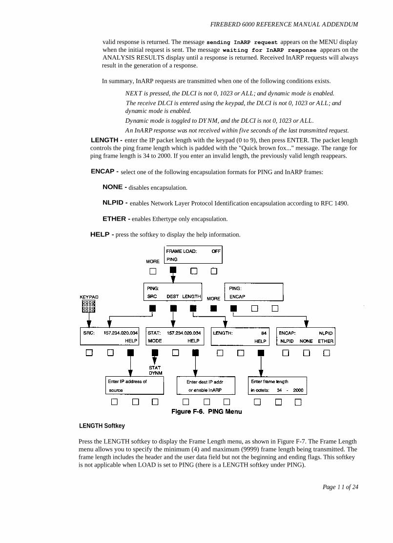
PING - allows you to specify source, destination, encapsulation method, and IP datagram length, as shownin Figure F-6. This function enables in-service connectivity testing and round trip delay measurements to beperformed between IP configured frame relay routers and the FIREBERD 6000 or between FIREBERD6000s. The FIREBERD 6000 can PING an IP router or another FIREBERD 6000. An IP router can alsoPING a FIREBERD 6000 (the FIREBERD 6000 supplies ICMP echo reply). Changing any ping parametercauses a test restart.
NOTE
PING and InARP frames are sent only on the DLCI selected from the Results on DLCIMenu (RXDLCI softkey).
The PING menu softkeys perform the following functions:
SRC - enter the IP source address of the ping-transmitting unit with the keypad (0 to 9), then pressENTER. The range for each address field is 000 to 255. If an invalid address is entered, the previousaddress reappears. This address is also used in response to received InARP requests.
DEST - enables automatic and manual selection of the IP destination address for the echo-reply unit.Manual selection is used when the IP address is known. When the IP source address is unknown, theInARP feature of Ping enables the user to generate and transmit a request to the far end device of anyPVC and obtain its IP address. It also enables the far end device to request the FIREBERD's IP address.The IP address recovered is used as the destination address for PING. When selected, the softkeyMODE displays.
MODE - controls automatic IP addressing. The options are STAT and DYNM for static (manual)address selection and dynamic (automatic) InARP selection, respectively. When pressed, this soft-key toggles between these modes. The active mode appears on the top line of the MENU display.
Static mode enables manual selection of the IP address. Using the keypad, select an IP address,ranging 000 to 255 for each address field. The echo-reply unit source address must match the ping-transmitting unit destination address. Press ENTER to implement the new address. If the address isoutside the range or invalid, the previous address is restored.
Dynamic mode enables the transmission of InARP requests. To send an InARP request, pressMODE until DYNM appears in the MENU display. Select the DLCI for transmission from theResults On DLCI Menu (RXDLCI softkey) as the InARP request will be transmitted on theRXDLCI (transmit and receive DLCIs are linked for InARP functionality), see Figure F-2.InARP requests are transmitted on one DLCI at a time and are not transmitted on DLCI 0 or 1023.If ALL is selected for the RXDLCI, the last configured receive DLCI is used. If a DLCI has notbeen configured, RXDLCI 25 is the default. Each time NEXT is pressed, a new InARP request istransmitted on the new DLCI. Once initiated, InARP requests are sent every five seconds until a
FIREBERD 6000 REFERENCE MANUAL ADDENDUM
valid response is returned. The message sending InARP request appears on the MENU displaywhen the initial request is sent. The message waiting for InARP response appears on theANALYSIS RESULTS display until a response is returned. Received InARP requests will alwaysresult in the generation of a response.
In summary, InARP requests are transmitted when one of the following conditions exists.
NEXT is pressed, the DLCI is not 0, 1023 or ALL; and dynamic mode is enabled.
The receive DLCI is entered using the keypad, the DLCI is not 0, 1023 or ALL; anddynamic mode is enabled.
Dynamic mode is toggled to DYNM, and the DLCI is not 0, 1023 or ALL.
An InARP response was not received within five seconds of the last transmitted request.
LENGTH - enter the IP packet length with the keypad (0 to 9), then press ENTER. The packet lengthcontrols the ping frame length which is padded with the "Quick brown fox..." message. The range forping frame length is 34 to 2000. If you enter an invalid length, the previously valid length reappears.
ENCAP - select one of the following encapsulation formats for PING and InARP frames:
NONE - disables encapsulation.
NLPID - enables Network Layer Protocol Identification encapsulation according to RFC 1490.
ETHER - enables Ethertype only encapsulation.
HELP - press the softkey to display the help information.
LENGTH Softkey
Press the LENGTH softkey to display the Frame Length menu, as shown in Figure F-7. The Frame Lengthmenu allows you to specify the minimum (4) and maximum (9999) frame length being transmitted. Theframe length includes the header and the user data field but not the beginning and ending flags. This softkeyis not applicable when LOAD is set to PING (there is a LENGTH softkey under PING).
Page 1 1 of 24

FIREBERD 6000 REFERENCE MANUAL ADDENDUM
F3.4
Link Management Menu
Page 1 2 of 24
FRAME TRANSMIT: OFF
HEADER LOAD LENGTH
E] E]
NOTE
NOTE
Frame length in
octets: 4 - 9999
0 0 0
Figure F-7. Frame Length Menu
The Frame Length menu softkeys perform the following functions:
MIN - press the softkey to move the cursor under the most significant digit for the minimum frame lengthfield (on the left). Enter the minimum information frame length (in octets from 4 to 9999) by using thekeypad (0 to 9), then press ENTER. If you enter an invalid frame length, the previously valid frame lengthreappears.
For lost frame analysis, the minimum frame length must be at least 16 bytes.
MAX - press the softkey to move the cursor under the most significant digit for the maximum frame lengthfield (on the right). Enter the maximum information frame length (in octets from 4 to 9999) by using thekeypad (0 to 9), then press ENTER. If you enter an invalid frame length, the previously valid frame lengthreappears.
HELP - press the softkey to display the help information.
If you set the MIN value greater than the MAX value or set MAX to a value less thanMIN, pressing ENTER automatically sets the MAX value equal to the MIN value setting.To transmit frames of equal length, set the MIN value equal to the MAX value.
Pressing the LNKMGT softkey displays the Link Management menu, as shown in Figure F-8. The LinkManagement menu allows you to specify the link management type, poll status rate, duration, and interface.

The Link Management menu softkeys perform the following functions:
TYPE - press the softkey to display the Link Management Type menu. The Link Management Type menuallows you to select the type of link management to be used. The Link Management Type menu softkeysperform the following functions:
OFF - no link management is selected (Unsupported).
617-D - selects the ANSI T1.617 Annex D link management.
LMI - selects the frame relay consortium local management interface.
Q933-A - selects ITU (CCITT) Q.933 Annex A link management.
RATE - press the softkey to display the Status Poll menu. The Status Poll menu displays the time intervalbetween "STATUS ENQUIRY" polls transmitted by the FIREBERD 6000 to the network. The Status Pollmenu softkeys perform the following functions:
UP - press the softkey to increment the status poll interval from 5 to 30 seconds in 5-second steps.
DOWN - press the softkey to decrement the status poll interval from 30 to 5 seconds in 5-second steps.
FULL - press the softkey to display the Full Status Poll menu. The displayed value indicates the intervalbetween full status enquiry polls (measured in the number of status polls). Setting this menu to 5 and theStatus Poll menu rate to 10, causes a full status poll to be transmitted every 50 seconds.
Keypad (0 to 9) - enter the full status enquiry poll interval from 1 to 255, then press ENTER. If youenter an invalid time, the previously valid time reappears.
HELP - press the softkey to display the help information.
Page 13 of 24
FIREBERD 6000 REFERENCE MANUAL ADDENDUM
Figure F-8. Link Management Menu

FIREBERD 6000 REFERENCE MANUAL ADDENDUM
INTF - press the softkey to display the Network Interface menu. The Network Interface menu allows you toselect the direction in relation to the network. The Network Interface menu softkeys perform the followingfunctions:
UNI-U - press the softkey to select the user (DTE) side of the user-network interface.
UNI-N - press the softkey to select the network (DCE) side of the user-network interface.
NNI - press the softkey to select bidirectional network-network interface.
F3.5
Frame Relay Status Indicators and Messages
The PATTERN SYNC LED indicates valid frame relay frames (on any DLCI) are being received. If no validframes are received for 31 seconds then a synchronization loss is declared.
When the Frame Relay option is enabled, the BER analysis capability of the FIREBERD 6000 is notavailable. This means that pattern-related results (e.g., Bit Errors, BER, etc.) are not available when theFrame Relay option is active.
The messages Receiver Overrun Error and Transmitter Underrun Error occur when theFrame Relay system is receiving more frame relay traffic than can be processed, or is transmitting moretraffic than can be processed, respectively. As a result, errored frames cannot be counted. To correct this,lower the rate at which the data is being transmitted to the FIREBERD 6000.
All other indicators and switches are based on the current interface selected.
F4.
AVAILABLE FRAME RELAY RESULTS
The following ERROR and PERFORMANCE category results are provided when the Frame Relay option isenabled.
F4.6
ERROR Category Results
The following test results appear in the ERROR Category.
TX PNG - number of ping packets/frames transmitted by the FIREBERD 6000. The result onlyappears when the transmit frame load is set to PING.
ECHO PNG - number of successful echo replies transmitted by the FIREBERD 6000. The destinationaddress within the arriving ping packet must match the source address of the unit transmitting the echoreply. The destination address of the unit transmitting an echo reply can be blank or incorrect, it isirrelevant. When the 12 FRAME RELAY auxiliary function is enabled, the result is incremented in anymode.
LOST PNG - number of ping packets that were not echoed back to the FIREBERD 6000; includingout of order echo reply packets and corrupted echo reply packets. The result is not used in delaycalculations. The result only appears when the transmit frame load is set to PING.
FRM CNT - a count of the total number of frame relay frames detected (including errored and abortedframes). This result can be calculated across all DLCIs or for one specific DLCI.
Page 14 of 24

FIREBERD 6000 REFERENCE MANUAL ADDENDUM
FRM OCTS - a count of the total number of octets received in valid frame relay frames. This result canbe calculated across all DLCIs or for one specific DLCI.
FRM RATE - the average number of frames per second received since the start of the test.
AVG FRM - the average frame size calculated as the number of FRM OCTS divided by the FRM CNTnumber. This result can be calculated across all DLCIs or for one specific DLCI.
FCS ERRS - a count of the valid frame relay frames which have FCS errors. This result is calculatedacross all DLCIs. The number of errored frames incrementing indicates that there is a Physical Layerimpairment on the monitored link.
ABRT FRM - a count of the aborted frame relay frames detected (excluding out of frame aborts). Thisresult is calculated across all DLCIs. An aborted frame indicates the frame has become all is and thatthe link is dead or the switch on the other end stopped a frame in the middle of its transmission.
SHRT FRM - a count of the valid frames that are less than 4 bytes long, excluding flags. This result iscalculated across all DLCIs. The incrementing of short frames indicates a network equipment fault.
FECN FRM - a count of valid frames with the Forward Explicit Congestion Notification (FECN) bitset (i.e., 1). This result can be calculated across all DLCIs or for one specific DLCI. This resultincrementing indicates that the network is detecting congestion along the PVC at the receiving DLCI.Reducing the transmission frame relay rate is recommended.
BECN FRM - a count of valid frames with the Backward Explicit Congestion Notification (BECN) bitset (i.e., 1). This result can be calculated across all DLCIs or for one specific DLCI. When this result isincrementing, it indicates that frames transmitted on the PVC, for which BECN is set, are either causingor encountering congestion. Reducing the transmitted frame load should help to alleviate the condition.
DE FRM - a count of valid frames with the DE bit set (i.e., 1). This result can be calculated across allDLCIs or for one specific DLCI. When this result is incrementing, it indicates that received frames arebeing marked as "discard eligible". This occurs because: 1) The far-end device is indicating that theframes can be discarded, or 2) The network is receiving frames from the far-end device at a rate thatexceeds the committed information rate (CIR).
LOST FRM - a count of FIREBERD 6000 test frames that appear to have been lost by the network,based on gaps in the test frames sequence number. This result increments to indicate that frames arebeing dropped from the network. Frames are dropped by the network when the frame is errored (has aninvalid FCS) or is discarded because of congestion or over-utilization. When generating frames on oneDLCI, set the receive DLCI to the corresponding transmit DLCI to guarantee an accurate result. Thisresult is not valid when the FIREBERD 6000 is transmitting on more than one DLCI.
LMI MSGS - the total number of LMI status or enquiry messages received since the start of the test ifLMI INTF is UNI-U or UNI-N, respectively. An incrementing count for this result indicates a"heartbeat".
LMI ENQS -the number of LMI status enquiry messages received if LMI INTF is NNI.
LMI STAT - the number of LMI status messages received if LMI INTF is NNI.
LMI ERRS - the total number of LMI errors detected. LMI errors indicate that the receive sequencenumber is not equal to the last transmitted send sequence number. This result incrementing indicatesthat the link management handshaking is not operating correctly.
Page 15 of 24

FIREBERD 6000 REFERENCE MANUAL ADDENDUM
Page 16 of 24
LMI TMOS - the number of LMI timeouts. Indicates nonreceipt of a STATUS message within a pollinginterval after a STATUS ENQUIRY has been sent. This result incrementing indicates that the link fromyour FIREBERD 6000 to the network switch is down, that the link from the switch to you is down, orthat the switch is down.
The LMI results are only available when the Link Management Type is set to LMI, 617-D,or Q933-A.
PVC STAT - the current status of the selected DLCI. This result is only available when one specificDLCI is analyzed. This is the status that the switch is reporting. The PVC STAT result can have thefollowing possible values.
Result Value:
Meaning:
NOTE
"" DLCI is undefinedINACTIVE
DLCI is inactiveNEW
DLCI was just addedDELETED
DLCI was just deletedRNR
DLCI status is RNRACTIVE
DLCI is activeNO STAT
DLCI is in use, but was not included in last status message
F.4.7
PERFORMANCE Category Results
The following test results appear in the PERFORMANCE Category:
MIN PNG - minimum round trip delay, in milliseconds, since the beginning of the test based on thetime difference between a transmitted ping and a successfully received echo reply. Resolution is 100 us.The result only appears when the transmit frame load is set to PING.
MAX PNG - maximum round trip delay, in milliseconds, since the beginning of the test based on thetime difference between a transmitted ping and a successfully received echo reply. Resolution is 100 us.The result only appears when the transmit frame load is set to PING.
AVG PNG - average round trip delay, in milliseconds, since the beginning of the test based on the timedifference between a transmitted ping and a successfully received echo reply. Resolution is 100 us. Theresult only appears when the transmit frame load is set to PING.
AVG%UTIL - the average percentage of link utilization on the received channel since the start of thetest calculated as the number of FRM OCTS divided by the total number of octets received. This resultcan be calculated across all DLCIs or for one specific DLCI.
MAX%UTIL - the maximum percentage of link utilization on the received channel in any one secondsince the start of the test. This result can be calculated across all DLCIs or for one specific DLCI.
AVG TPUT - the average received throughput since the start of the test, calculated as total receivedUser Data Field (UDF) bits divided by the total seconds. This result can be calculated across all DLCIsor for one specific DLCI. This result can be used to estimate the CIR.
MAX TPUT - the maximum received throughput during any one second since the start of the test. Thisresult can be calculated across all DLCIs or for one specific DLCI.

F.4.8
Error Print Results
The FCS ERRS and ABRT FRM results are able to generate error prints.
F4.9
Delta Print Results
The following results can appear in delta prints:
ABRT FRMAVG%UTILBECN FRMDE FRMFCS ERRSFECN FRMFRM CNTFRM OCTSLOST FRMMAX%UTIL
F4.10
Results Prints
When the Frame Relay option is selected, the standard results print additionally prints the following results:
ABRT FRMAVG TPUTAVG%UTILFCS ERRSFRM CNTFRM OCTSLOST FRM
All results are displayed for long result prints.
F4.11
Histogram Results
The following are results that can be selected to generate a histogram print:
ABRT FRMBECN FRMDE FRMFCS ERRSFECN FRMFRM CNTFRM OCTSLOST FRM
F5.
LINK LAYER ANALYSIS
FIREBERD 6000 REFERENCE MANUAL ADDENDUM
Link Layer analysis is performed in a monitoring or link terminating configuration. This allows statistics onthe frame relay to be collected. The Link Layer analysis capability enables you to:
Accumulate the following Link Layer statistics computed across the entire bandwidth, or for a
single DLCI that you specify:
Page 1 7 of 24

FIREBERD 6000 REFERENCE MANUAL ADDENDUM
F6.
LOAD GENERATION AND ANALYSIS
Page 1 8 of 24
When used in a link terminating configuration, the Frame Relay option can transmit FIREBERD 6000 testframes according to load parameters that you specify.
This ability to generate test frames meets or exceeds the following requirements.
Total Frame Octets ReceivedTotal Frames ReceivedAverage Frame SizeFrames with the FECN Bit SetFrames with the BECN Bit SetFrames with the DE Bit SetErrored FramesAborted FramesShort FramesAverage Throughput (kb/s)Maximum Throughput (kb/s)Average % UtilizationMaximum % Utilization
Generates fixed length frames with a total length of between 4 and 9999 octets; or
Generates random length frames within a minimum and maximum length, which you specify (4 to9999 octets) (flags are not included in the length specified).
Generates frames at a fixed utilization between 1 and 10,000 kb/s, in 1 kb/s increments with theload distributed over the full link capacity (flags are not included in the length specified).; or
Generates frames with a bursty utilization, at 100% utilization for 00.1 to 30.0 seconds, then at a
0% utilization (idle) for 00.1 to 30.0 seconds.
Generates frames for one or multiple DLCIs (1 to 10), allowing you to control the state of theFECN, BECN, DE, and/or C/R bits.
Generates frames of sufficient length to conform with RFC 1490, with the Network Layer Protocol
Identifier (NLPID) and Subnetwork Access Protocol (SNAP) header ID set to identify the frame asa FIREBERD 6000 test frame. The user data in generated frames consists of a sequential count(from 0 to 65536), and the remainder of the data is a fixed pattern. Generated frames that do nothave a length sufficient to conform with RFC 1490 will be a truncated form of the standard testframe. Note that the Frame Relay option supports AUX 04 (Single Transmit Mode).
Received FIREBERD 6000 test frames have their sequence number analyzed for lost frames
(LOST FRM), in addition to the standard Link Layer analysis described previously. Lost frameanalysis is only valid in single TX/RX analysis mode.
F7.
LMI ANALYSIS AND EMULATION
The Frame Relay option decodes Local Management Interface (LMI) messages to provide PVC and linkstatus information in the form of LMI results. LMI messages are available whether in monitoring orterminating configurations.
In terminating configurations, LMI emulation can be configured for the user or the network side of the UNI,or for the NNI. The LMI analysis/emulation capability meets or exceeds the following requirements:
FIREBERD 6000 REFERENCE MANUAL ADDENDUM
Supports either ANSI T1.617 Annex D, the Frame Relay Forum scheme (optional extensions arenot presently supported), or ITU Q.933 Annex A.
Provides a user-selectable heartbeat polling (from 5 to 30 seconds), in 5-second increments.
Provides a user-selectable full status polling interval (from 1 to 255 poll cycles).
Provides the following LMI-derived results:
LMI MSGSLMI ERRSLMI TMOSPVC STATLMI ENQS (NNI mode only)LMI STAT (NNI mode only)
F8.
REMOTE CONTROL COMMANDS
Remote control commands used to control the Frame Relay option are described in the followingparagraphs. The FIREBERD 6000 adheres to the IEEE-488.2 remote control syntax.
AUX:FRAME_RELAY OFFTurns off the Frame Relay option.
AUX:FRAME_RELAY ONTurns on the Frame Relay option.
AUX:FRAME_RELAY TX_RXPlaces the Frame Relay option in Transmit/Receive (Emulation) mode.
AUX:FRAME_RELAY RXPlaces the Frame Relay option in Receive-Only (Monitor) mode.
AUX:FRAME_RELAY?Requests the status of the Frame Relay option.
AUX:FRAME_RELAY.BURST_TIME xxxSets the burst time in tenths of a second (where xxx = 001 to 300).
AUX:FRAME_RELAY:BURSTTIME?Requests the current burst time selection.
AUX:FRAME_RELAY DLCI_MON xxxxSelects the DLCI to be monitored (where xxxx = All, NEXT, or 0 to 1023).
AUX:FRAME_RELAY.DLCI_MON?Requests the DLCI being monitored.
AUX:FRAME_RELAY FIXED-RATE xxxxxSets the fixed rate, in kb/s (where xxxxx = 1 to 10000).
AUX:FRAME_RELAYFIXED_RATE?Requests the fixed rate selection.
AUX:FRAME_RELAYHEADER:BECN [OFF I ON]Sets the BECN bit (where OFF = 0 and ON = 1).
AUX:FRAME_RELAYHEADER:BECN?Requests the BECN bit value.
AUX:FRAME_RELAY:HEADER:CR [OFF I ON]Sets the C/R bit (where OFF = 0 and ON = 1).
AUX:FRAME_RELAYHEADER:CR?Requests the C/R bit value.
Page 1 9 of 24

FIREBERD 6000 REFERENCE MANUAL ADDENDUM
Page 20 of 24
AUX:FRAME RELAY:HEADER:DE [OFF I ON]Sets the DE bit (where OFF = 0 and ON = 1).
AUX:FRAME_RELAY:HEADER:DE?Requests the DE bit value.
AUX:FRAME_RELAY HEADER:DLCI nn, xxxxSets the DLCI header (where nn = 1 to 10 and xxxx = 0 to 1023).
AUX:FRAME_RELAY:HEADER:DLCI? nnRequests the DLCI header number.
AUX:FRAME_RELAY.HEADER:DLCI_ADD xxxxAdds a new transmitted DLCI (where xxxx = 0 to 1022).
AUX:FRAME_RELAY:HEADER:DLCI_num?Requests number of DLCI entries.
AUX:FRAME RELAY HEADER:DLCI REMOVE nnRemoves DLCI entry (where nn = 1 to 10).
AUX:FRAME_RELAY:HEADER:FECN [OFF I ON]Sets the FECN bit (where OFF = 0 and ON = 1).
AUX:FRAME_RELAYHEADER:FECN?Requests the FECN bit value.
AUX:FRAME_RELAY:mLE_T1ME xxxSets the idle time, in tenths of a second (where xxx = 001 to 300).
AUX:FRAME_RELAY-IDLE-TIME?Requests the current idle time selection.
AUX:FRAME_RELAY.LNKMGT [OFF 1617-D I LMI I Q933-A]Sets the link management type (where OFF = none, 617-D = ANSI T1.617 Annex D,LMI = Frame Relay Forum, and Q933-A = Q.933 Recommendation).
AUX:FRAME_RELAYLNKMGT?Requests the frame relay link management type.
AUX:FRAME_RELAYLNKMGT:FULL xxxSets the number of full LMI status polls that are sent (where xxx = 001 to 255).
AUX:FRAME_RELAYLNKMGT:FULL?Requests the number of full LMI status polls that are to be sent.
AUX:FRAME RELAYLNKMGT:INTF [UNI-U I UNI-N I NNI]Sets the link management interface type (where UNI-U = User Network Interface - User Side,UNI-N = User Network Interface - Network Side, and NNI = Network-Network Interface).
AUX:FRAME_RELAYLNKMGT:INTF?Requests the link management user network interface type.
AUX:FRAME_RELAY:LNKMGT:POLL xxSets the frequency (how often) LMIs are sent, in seconds (where xx = 5 to 30, dividable by 5).
AUX:FRAME_RELAY:LNKMGT:POLL?Requests the LMI poll interval time.
AUX:FRAME_RELAY-MAX-LENGTH xxxxSets the maximum frame relay length (where xxxx = 4 to 9999).
AUX:FRAME_RELAYMAX_LENGTH?Requests the maximum frame relay length selection.
AUX:FRAME RELAY MIN LENGTH xxxxSets the minimum frame relay length (where xxxx = 4 to 9999).
AUX:FRAME_RELAY-MIN-LENGTH?Requests the minimum frame relay length selection.
AUX:FRAME RELAY:TX_LOAD [OFF I BURST I FIXED I PING]Sets the type of transmit load (where OFF = no transmission, BURST = transmission for the burst time,FIXED = the set rate (in kb/s) up to 10 Mb/s, and PING = enable PING function).
AUX:FRAME_RELAY-TX-LOAD?Requests the TX load selection.
AUX:FRAME_RELAY:TX_LOAD:PING DEST "xxx.xxx.xxx.xxx"Sets the IP destination address (where xxx = 000 to 255).

FIREBERD 6000 REFERENCE MANUAL ADDENDUM
Frame relay is a streamlined protocol since it does not provide for error correction. It provides higherperformance and greater efficiency, allowing greater throughput and bandwidth on demand. Frame relayaccomplishes this by statistically multiplexing many logical data conversations (called virtual circuits) overa single physical transmission link. This statistical multiplexing provides a more flexible and efficientutilization of available bandwidth.
Due to recent improvements in digital transmission technology, wide area networks have producedtransmission links with BERs (Bit Error Rates) of 1 in 100,000,000 bits. As a result of low BERs, Data LinkLayer (Layer 2 of the ISO Reference Model) protocols can forego the link-by-link error correctionalgorithms, leaving this function to be performed by higher layers of protocol when necessary. This allowsfor greater performance and efficiency without sacrificing data integrity.
Frame relay was designed with this approach in mind. Frame relay provides a FCS (Frame Check Sequence)for the purpose of detecting corrupted data bits, but does not provide any means for correcting errors.Corrupted frames are simply discarded as they are encountered.Due to the widespread use of higher layer protocols used to perform flow control, frame relay does notinclude explicit flow control procedures, since doing so would be redundant with those in higher layers.However, frame relay does provide a very simple congestion notification mechanism to allow a network toinform a user device (DTE) when the network has reached a congested state.
The frame relay frame is shown in Figure F-9 and is delimited by flags at the beginning (opening flag) andending of the frame (closing flag). All frame relay frames start and end with the following 8-bit flagsequence: one 0 bit followed by six consecutive 1 bits and one 0 bit.
Figure F-9. Frame Relay Frame Format
The frame relay frame is transmitted from left to right and the octets are transmitted from top to bottom andis described as follows:
DLCI - Data Link Connection Identifier Address field (the MSB is Bit 8 in Octet 2 and the LSB is Bit5 in Octet 3). The DLCI values available for use are determined by the service being provided.
C/R - Command/Response Indicator. The C/R bit, when implemented, is used (by the end user, not thenetwork) to indicate whether the frame is a command or a response. Frame relay does not make use ofthis bit.
FECN - Forward Explicit Congestion Notification. The FECN bit is set by the network to notify theuser that congestion avoidance procedures should be initiated, where applicable, for traffic in thedirection of the frame carrying the FECN notification. The FECN bit is set to 1 in the direction of the
Page 22 of 24

FIREBERD 6000 REFERENCE MANUAL ADDENDUM
congestion to notify the user that the network is congested. This bit is set to 1 to indicate to the receivingend-system that the frames it is receiving have encountered congested resources.
BECN - Backward Explicit Congestion Notification. The BECN bit is set by the network to notify theuser that congestion avoidance procedures should be initiated, where applicable, for traffic in theopposite direction of the frame carrying the BECN notification. The BECN bit is set to 1 in the oppositedirection of the congestion to notify the user that the network is congested. This bit is set to 1 to indicateto the receiving end-system that the frames it is transmitting have encountered congested resources.
EA - Address Field Extension Bit Indicator. The EA bit is the first bit of each octet (byte) of theaddress field. When the EA bit is set to 0, it indicates that another octet is following in the address field.When the EA bit is set to 1, it indicates that it is the last octet and that no other octet is following in theaddress field. The FIREBERD 6000 only supports 2 octet addresses.
DE - Discard Eligibility. The DE bit is set to 1 to indicate that this frame is eligible to be discardedinstead of other frames when congestion is encountered. The network may discard a frame that has theDE bit set to 1 if the frame is routed across a point where congestion is occurring. However, if at thepoint where congestion is occurring and all frames with the DE bit set to 1 have been dropped andcongestion still exists, the network will begin dropping frames that have their DE bit set to 0. The DE bitis typically set by the network when the user traffic has exceeded their negotiated parameters.
I nformation Field - User data. The information field contains the data that the user is transmitting.The maximum length of this field is determined by the service provider.
FCS - Frame Check Sequence. The FCS field is used to determine whether the address field andinformation field contain any errors. Frames with an invalid FCS are discarded by the network. The FCSis considered to be invalid when the FCS calculated on the received frame does not match the FCSwithin the frame.
Frame Abort - A frame with 7 or more consecutive 1 bits is a frame abort sequence. Upon receipt ofthe frame abort sequence, the network discards the frame. All received data following the Abort Frameis discarded, up until the next valid flag is received.
F10.
FRAME RELAY TESTING
You can use the Frame Relay option to:
Perform complete physical layer testing of the local loop (or between nodes).
Verify proper Link Management operation.
Route frames across the network on a specific DLCI.
Stress the network by transmitting frames (and monitoring at the receiving end).
Non-intrusively monitor frame relay traffic on live data (excluding HSSI).
Ping in-service routers and measure round trip delay.
Testing is considered to be intrusive (interrupting data) or non-intrusive (monitoring live data). Sinceintrusive testing is performed basically the same way as BER Physical Layer testing, only non-intrusivetesting is discussed in the following paragraphs.
Page 23 of 24

FIREBERD 6000 REFERENCE MANUAL ADDENDUM
F.10.13 In-Service Monitoring
Page 24 of 24
You can perform non-intrusive monitoring of live data by using the V.35 "Y" cable and theRS449/V.35/306/X.21 interface (Model 42522) or the V35/306 DTE/DCE interface (Model 40202).
NOTE
When performing tests with the V35 "Y" cable (Part No. 43013-01), the maximum datarate recommended is 2 Mb/s.
When monitoring a T1 circuit, you can also use a bridging cable, a DSX MON jack, or any availablemonitor access point. The following steps describe the procedure for performing in-service monitoring.
2.
3.
4.
5.
6.
7.
8.
9.
With the FIREBERD 6000 power turned OFF, insert the T1/FT1 interface in the vacant interfaceslot on the rear panel.
Turn ON the FIREBERD 6000 power.
Press the MENU switch until INTF SETUP illuminates. First set the T1/FT1 CONFIG and MODEparameters.
Press the MENU switch until the AUXILIARY LED illuminates.
Press the 1 and 2 keys on the keypad, then press ENTER to display the 12 FRAME RELAYauxiliary function. Be sure ON appears. If not, press the softkey below ON to enable the FrameRelay option.
Configure the link management for the frame relay circuit being monitored by pressing theLNKMGT softkey to display the selected link management. Be sure the displayed linkmanagement matches the link management for the frame relay circuit being monitored.
Adjust the link management interface to the opposite of what you are monitoring at the U interface.(i.e., select UNI-N when monitoring traffic from the DTE and select UNI-U when monitoringtraffic from the switch).
As a precaution, verify that no frames are being transmitted by pressing the LOAD softkey. Be surethat OFF is displayed for the FRAME LOAD menu. If it is not, press the OFF softkey. (This is donesince we are only monitoring data.)
Connect the bantam cable from the RX interface connector to the DSX MON jack to monitor dataon the circuit you desire.
Press the RESTART key to clear any result values and begin monitoring live data.
Copyright 1996 TTC®20400 Observation Drive, Germantown, Maryland 20876-4023 USAUSA 1-800-638-2049 • +1-301-353-1550 (MD) • FAX +1-301-353-0234
Canada 1-888-689-2165 • +1905-507-4117 o FAX +1-905-507-4126www.ttc.com
FIREBERD and TTC are registered trademarks of TTC. All other product names mentioned in this document are trademarks of their respective owners.Specifications, terms, and conditions are subject to change without notice.