advanced test equipment rentals - atecorp.com€¦ · site master can pinpoint the antenna problem...
TRANSCRIPT

Anritsu's handheld, battery operated Broadband Site Master is the most accurate and convenient tool available for fieldinstallation, verification, troubleshooting and repair of microwave cables and communication systems. With calibratedvector error correction and a convenient user interface, difficult test specifications become easy to verify, quality isimproved, and maintenance expenses are reduced.
The Broadband Site Master targets microwave site installers, point-to-point operators, point-to-multipoint operators, radiomanufacturers, private/public networks that support microwave links, and defense programs responsible for theinstallation and maintenance of microwave cables. The Broadband Site Master models test both waveguide and coaxialcables more conveniently than laboratory sized scalar analyzers or microwave test sets.
Enhanced Performance and FunctionalityThe Broadband Site Master offers the following improvements over the preceding model:
• Increased frequency range to cover 25 MHz to 20 GHz with a single connection
• Updated thin film transistor (TFT) color display that is easily viewable indirect sunlight
• Increased measurement speed so screen updates occur in real time
• Faster distance-to-fault (DTF) calculations allow real time updates
• Added GPS functionality enables data to be stored with latitude, longitude, andaltitude information
Cost Savings and Quality ImprovementMarket competition requires operators to reduce per site maintenance expenses. Site Master's Frequency DomainReflectometry (FDR) technique breaks away from the traditional fix-after-failure maintenance process by finding small,hard to identify problems before major failures occur.
Sixty to eighty percent of a typical cell site's problems are caused by problematic cables, connectors and antennas. Cablesinstalled in aircraft and on-board ships are difficult to troubleshoot and can cause extensive down time. When cables aredamaged, mis-positioned, or contaminated with moisture, Site Master identifies the problem quickly. Antenna degradationreduces the cell coverage pattern. Site Master can pinpoint the antenna problem from ground level in a few seconds soclimbing the antenna tower becomes unnecessary.
FDR TechniqueFrequency Domain Reflectometry (FDR) and Time DomainReflectometry (TDR) have similar acronyms, and both techniquesare used to test transmission lines. But that's where the similaritiesend. The TDR technique is not sensitive to RF problems. The TDRstimulus is a DC pulse, not RF. Thus, TDR is unable to detectsystem faults that often lead to system failures. Additionally, theFDR technique saves costly, time-consuming trouble shootingefforts by testing cable feedline and antenna systems at theirproper operating frequency. Deficient connectors, lightningarrestors, cables, jumpers, or antennas are replaced before callquality is compromised.
2
The Leading Handheld Broadband Microwave Transmission Line and Antenna Analyzer
The TDR pulse energy is not as useful for higher frequency
applications as the FDR approach implemented in Site Master.
Advanced Test Equipment Rentalswww.atecorp.com 800-404-ATEC (2832)
®
Established 1981

Site Master performs various RF measurements aimed at simplifying transmission line and antenna system analysis:Return Loss, SWR, Cable Loss, and Distance-to-Fault (DTF). A single soft key selection on the main menu activatesthe desired measurement mode.
Return Loss, SWR
Return Loss and SWR measurements ensure conformance tosystem performance specifications. The measurement can easily betoggled between either one of the two modes and can be performedwithout climbing the tower.
Cable LossCable Loss measurements determine the level of insertion loss withinthe cable feedline system. Insertion loss can be verified prior todeployment, when you have access to both ends of the cable, oron installed cables without access to the opposite end.
Distance-to-FaultAlthough a Return Loss test can tell users the magnitude of signalreflections, it cannot tell the precise location of a fault withinthe cable system. A Distance-to-Fault measurement providesthe clearest indication of trouble areas as it gives both the magnitudeof signal reflection and the location of the signal anomaly.
Vector Error Correction
Vector error correction within the S8x0 “D” Series improves the quality and convenience of measurements compared totraditional scalar techniques. Accuracy and repeatability are enhanced as errors such as test port match and source matchare removed.
Waveguide Dispersion and CalibrationVector error correction using FDR improves the quality of Distance-to-Fault data. Not only is the reflection magnitudemore accurate, but the waveguide dispersion correction for fault location (different frequencies propagate at differentspeeds) is more accurate and repeatable. Unlike scalar-based systems, the Broadband Site Master S8x0 “D” Series does notsuffer reflection magnitude errors and length inaccuracies in proportion to the relative lengths of the coaxial input cableand waveguide under test.
Coaxial ConnectionsSite Master supports frequently used coaxial connectors suchas K, N, and TNC.
3
Insightful and Convenient Measurements
Easy to use and easy to view measurement results
Adapt to a variety of coaxial connectors
A short connection on oneend and the measurementoccurs at the other end

4
Transmission Line and Antenna Analyzer - Anywhere, Anytime
Functionality and BenefitsFunctionality Benefits
Cable and Antenna AnalyzerQuickly finds small, hard to identify faults beforemajor failures occur.
Power Monitor (S8x0D/5)Performs accurate power measurements with moreresolution in higher insertion loss situations.
GPS Receiver (S8x0D/31) Built-in receiver for location information.
Unit Dimensions
25.4 x 17.8 x 6.1 cm
(Actual Size Shown) Function Keys
Four dedicated function keys
simplify measurement tasks.
Rugged and ReliableChassis Design
Ruggedized, lightweight,
compact, high-impact housing
is designed to withstand repeated
drops and rough handling.
Weather resistant seals and
rubber membrane keypad protect
unit from dirt and moisture.
TFT Color DisplayStandard TFT (640x480) color
display featuring variable
brightness control. Viewable
in direct sunlight.

5
External DC Power Port
RF Out/Reflection 50Ω
RF Detector
GPS Antenna
Save and Recall Setup
25 setups for fast repeatable testing.
Limits
Create simple pass/fail measurements
with a single limit line, upper
and/or lower mask limits.
Multilingual User Interface
Multilingual user interface features on-screen
menus and messages in six different languages:
Chinese, English, French, German, Japanese,
and Spanish.
Save and Recall Display
Up to 200 memory locations. Alphanumeric data
labeling and automatic time/date stamp
simplifies data management.
Markers
Six markers for more comprehensive
measurements.
Soft Keys
Intuitive softkey menu
and user interface.
RS-232 Interface
Transfer stored data to and from
a personal computer (PC) or download
to printer via a serial cable for further
analysis. Use PC to automatically
control and collect data in the field.

6
Optional Features
Power Monitor (S8x0D/5)When cable losses or physical distances are too much for a one-port measurement, use an external synthesizer as a sourceand Option 5 with the 5400 and 560 Series RF Detectors as receivers to perform thru-line insertion loss measurements. Inaddition, the detectors can be used to measure absolute power levels (dBm or mW) over the broadband frequency rangeof the detector.
GPS Receiver (S8x0D/31)Built-in GPS provides location information (latitude, longitude,altitude) and Universal Time (UT) information. Site Master can stampeach trace with location information to check if the measurements aretaken at the right location. Site Master stores the GPS locationinformation until the unit is turned off. This stored locationinformation can be used to stamp traces taken indoors at the same cellsite location. The GPS option is offered with a magnet mount antennawith a 15 foot (~ 5m) cable to mount on the car or other useful surface.
Built-in GPS provides time and locationinformation using the optional GPSAntenna (2000-1410)
Handheld Software Tools™
Powerful data management and analysis software isprovided with every Site Master unit offering easy touse utilities for managing, archiving, and furtheranalyzing cable and antenna performance. Simplyconnect the serial cable between the Site Master anda Windows®-based PC to transfer data, analyzemeasurements, and compare with previousmeasurements.
Use Power Monitor to perform absolute power
measurements with or without an external synthesizer
Connect Site Master to a PC via a serial cable totransfer data or further analyze results
7
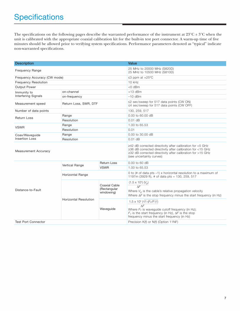
Specifications
The specifications on the following pages describe the warranted performance of the instrument at 23°C ± 3°C when theunit is calibrated with the appropriate coaxial calibration kit for the built-in test port connector. A warm-up time of fiveminutes should be allowed prior to verifying system specifications. Performance parameters denoted as “typical” indicatenon-warranted specifications.
Description Value
Frequency Range25 MHz to 20000 MHz (S820D)25 MHz to 10500 MHz (S810D)
Frequency Accuracy (CW mode) ≤3 ppm at +25ºC
Frequency Resolution 10 kHz
Output Power <0 dBm
Immunity to Interfering Signals
on-channel +13 dBm
on-frequency –10 dBm
Measurement speed Return Loss, SWR, DTF≤2 sec/sweep for 517 data points (CW ON)≤4 sec/sweep for 517 data points (CW OFF)
Number of data points 130, 259, 517
Return LossRange 0.00 to 60.00 dB
Resolution 0.01 dB
VSWRRange 1.00 to 65.53
Resolution 0.01
Coax/Waveguide Insertion Loss
Range 0.00 to 30.00 dB
Resolution 0.01 dB
Measurement Accuracy
≥42 dB corrected directivity after calibration for <5 GHz≥36 dB corrected directivity after calibration for <15 GHz≥32 dB corrected directivity after calibration for >15 GHz(see uncertainty curves)
Distance-to-Fault
Vertical RangeReturn Loss 0.00 to 60 dB
VSWR 1.00 to 65.53
Horizontal Range0 to (# of data pts –1) x horizontal resolution to a maximum of 1197m (3929 ft), # of data pts = 130, 259, 517
Horizontal Resolution
Coaxial Cable (Rectangular windowing)
(1.5 x 10⁸) (Vp)
∆F
Where Vp is the cable’s relative propagation velocity
Where ∆F is the stop frequency minus the start frequency (in Hz)
Waveguide
1.5 x 10⁸ (√1-(Fc/F1)2)
∆FWhere Fc is waveguide cutoff frequency (in Hz); F1 is the start frequency (in Hz), ∆F is the stop frequency minus the start frequency (in Hz)
Test Port Connector Precision K(f) or N(f) (Option 11NF)
8
Description Value
Language Support Chinese, English, French, German, Japanese, and Spanish
Internal Trace Memory Up to 200 traces
Setup Configurations 25
Custom Cable Configuration Memory 50 configurations
Display TFT color display with adjustable backlight
Ports
RF Out
Standard
Type k(f) test port, 50Ω+23 dBm (Peak), ±50 VDC, Maximum input without damage
Optional (S8x0D/11NF)
Type N(f) test port, 50Ω+23 dBm (Peak), ±50 VDC, Maximum input without damage
GPS In Reverse BNC(m), 50Ω For use with specified GPS antenna only
RF Detector Type N(m), 50Ω +20 dBm (Peak), Maximum input without damage
Serial Interface 9 pin D-sub RS-232 three wire serial
CEElectromagnetic Compatibility Meets European Community requirement EN61326-1:1998
Safety Meets European Community requirement EN61010-1:2001
Environmental (MIL-PRF- 28800FClass 2)
Temperature/Humidity
Operating –10ºC to 55ºC, humidity 85% or less
Non-operating–51ºC to +71ºC (recommend storing battery separately between 0ºC to +40ºC for any prolonged non-operating storage period)
MechanicalVibration Sine (5 to 55 Hz); Random (10 to 500 Hz)
Shock 30 G, 11 msec, half sine
Power SupplyExternal: DC input: +12 to +15 Volt DC, 3AInternal: NiMH battery: 10.8 volts, 1800 mAh
DimensionsSize (W x H x D) 25.4 cm x 17.8 cm x 6.1 cm (10.0 in x 7.0 in x 2.4 in)
Weight <2.28 kg (<5 lbs) including battery
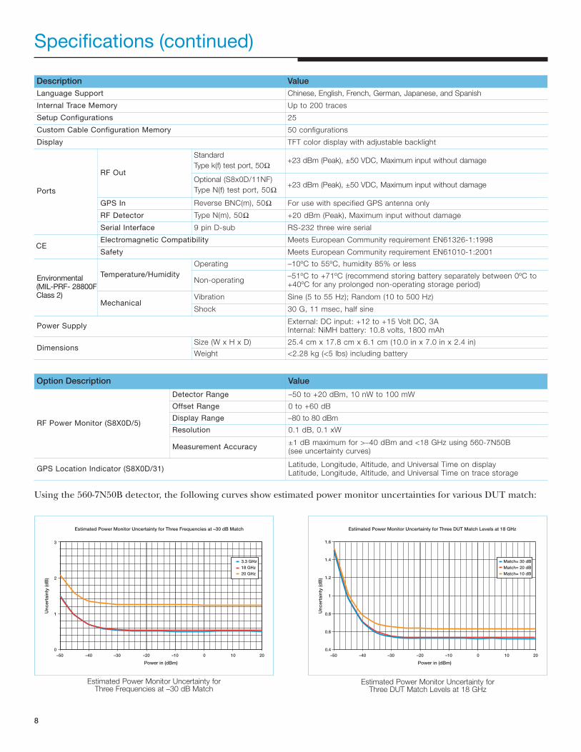
Specifications (continued)
Estimated Power Monitor Uncertainty for Three Frequencies at –30 dB Match
Power in (dBm)
Un
cert
ain
ty (d
B)
3.3 GHz
18 GHz
20 GHz
–50 –40 –30 –20 –10 0 10 20
2
3
1
0
Estimated Power Monitor Uncertainty for Three DUT Match Levels at 18 GHz
Power in (dBm)
Un
cert
ain
ty (d
B)
Match= 30 dB
Match= 20 dB
Match= 10 dB
–50 –40 –30 –20 –10 0 10 20
1
1.2
1.4
1.6
0.8
0.6
0.4
Using the 560-7N50B detector, the following curves show estimated power monitor uncertainties for various DUT match:
Option Description Value
RF Power Monitor (S8X0D/5)
Detector Range –50 to +20 dBm, 10 nW to 100 mW
Offset Range 0 to +60 dB
Display Range –80 to 80 dBm
Resolution 0.1 dB, 0.1 xW
Measurement Accuracy±1 dB maximum for >–40 dBm and <18 GHz using 560-7N50B (see uncertainty curves)
GPS Location Indicator (S8X0D/31)Latitude, Longitude, Altitude, and Universal Time on displayLatitude, Longitude, Altitude, and Universal Time on trace storage
Estimated Power Monitor Uncertainty for Three Frequencies at –30 dB Match
Estimated Power Monitor Uncertainty for Three DUT Match Levels at 18 GHz

Measurement Uncertainties
The following graphs provide measurement accuracy at 23°C ±3°C after vector error correction for the standardK and N connector types. The errors are worst case contributions of residual directivity, source match, frequencyresponse, network analyzer dynamic accuracy, and connector repeatability. In preparing these graphs, Fixed CW is ON.Calibration components 22K50 and 28K50 are used for K test port results. Calibration components 22N50 and 28N50-2 areused for the N test port results:
The reflection measurements of the 820D can be used to extract the insertion loss of cables or other devices when the farend of the device is terminated in a good reflector. The uncertainty in extracting the insertion loss is a function of basicmeasurement uncertainty and the base return loss of the device (often the cable's connector). The uncertainties areplotted versus the insertion loss to be measured as either the frequency or the base DUT’s return loss vary:
Reflection Magnitude Uncertainty (820D, k)
Mag
. U
ncert
ain
ty (d
B)
|S11| (dB)
<4 GHz
4-10 GHz
10-15 GHz
>15 GHz
10
1
0.1
–30 –25 –20 –15 –10 –5 0
Reflection Magnitude Uncertainty (820D, N)
Mag
. U
ncert
ain
ty (d
B)
|S11| (dB)
<4 GHz
4-10 GHz
10-15 GHz
>15 GHz
10
1
0.1
–30 –25 –20 –15 –10 –5 0
S820D Insertion Loss Uncertainty, DUT Match= –30dB
Un
cert
ain
ty (d
B)
Insertion Loss (dB)
10
1
0.1
0 1 2 3 4 5 6 7 8 9 10
<4 GHz
4-10 GHz
10-15 GHz
>15 GHz
Midband Insertion Loss Uncertainty vs. DUT Match
Un
cert
ain
ty (d
B)
Insertion Loss (dB)
10
1
0.1
0 1 2 3 4 5 6 7 8 9 10
–30 dB
–25 dB
–20 dB
9
Reflection Magnitude Uncertainty (S820D, K Connector)
S820D Insertion Loss Uncertainty, DUT Match = –30 dB S820D Insertion Loss Uncertainty vs. DUT Match, Frequency = 10 GHz
Reflection Magnitude Uncertainty (S820D, N Connector)

10
Ordering Information
Basic Models
Model Description
S810D Cable and Antenna Analyzer (25 MHz to 10.5 GHz)with built-in DTF, K(f) Test Port Connector
S820D Cable and Antenna Analyzer (25 MHz to 20 GHz)with built-in DTF, K(f) Test Port Connector
Options
Option Description
S8X0D/5 Power Monitor (Detector not included)
S8X0D/11NF Replaces standard K(f) Test Port Connector with N(f)
S8X0D/31 GPS Receiver (Antenna not included)
Standard Accessories• User's Guide
• Soft Carrying Case
• AC-DC Adapter
• Precision Adapter, Ruggedized K(m) to N(f)
• Automotive 12 Volt DC Adapter
• Handheld Software Tools CD ROM containing Fault Location (DTF),
Smith Chart and Software Data Management
• Serial Interface (Null Modem) Cable
• Rechargeable Battery, NiMH
DetectorsThe 5400 and 560 Series Detectors use zero-biased Schottky diodes.Measurement range is –55 dBm to +16 dBm using single cycle per sweep ACdetection, auto-zeroing with DC detection during the frequency sweep.Optional extender cables of over 3000 feet can be used with the S8x0D Series.Contact a local sales representative for special cables.
Maximum Input Power: +20 dBm
Standard Cable Length: 122 cm (4 ft.)
Dimensions: 7.6 x 2.9 x 2.2 cm (3 x 1-1/8 x 7/8 in.)
Weight: 170g (6 oz.)
Model Frequency Range Impedance Return Loss Input Connector Frequency Response
5400-71N50 0.001 to 3 GHz 50Ω 26 dB N(m)±0.2 dB, <1 GHz ±0.3 dB, <3 GHz
5400-71N75 0.001 to 3 GHz 75Ω26 dB, ≤2 GHz20 dB, ≤3 GHz
N(m)±0.2 dB, <1 GHz ±0.5 dB, <3 GHz
560-7A50 0.01 to 18 GHz 50Ω
15 dB, <0.04 GHz22 dB, <8 GHz17 dB, <18 GHz
GPC-7 ±0.5 dB, <3 GHz
560-7N50B 0.01 to 20 GHz 50Ω
15 dB, <0.04 GHz22 dB, <8 GHz17 dB, <18 GHz14 dB, <20 GHz
N(m)±0.5 dB, <18 GHz ±1.25 dB, <20 GHz
560-7S50B 0.01 to 20 GHz 50Ω
15 dB, <0.04 GHz 22 dB, <8 GHz 17 dB, <18 GHz 14 dB, <20 GHz
WSMA(m)±0.5 dB, <18 GHz ±2.0 dB, <20 GHz
560-7S50 –20.01 to 26.5 GHz 50Ω
16 dB, <0.04 GHz 22 dB, <8 GHz 17 dB, <18 GHz 14 dB, <26.5 GHz
WSMA(m)±0.5 dB, <18 GHz ±2.0 dB, <26.5 GHz
560-7K50 0.01 to 40 GHz 50Ω
13 dB, <0.04 GHz 22 dB, <8 GHz 17 dB, <8 GHz 16 dB, <26.5 GHz 15 dB, <32 GHz 13 dB, <40 GHz
K(m)
±0.5 dB, <18 GHz ±1.25 dB, <26.5 GHz ±2.2 dB, <32 GHz ±2.5 dB, <40 GHz
560-7VA50 0.01 to 50 GHz 50Ω
19 dB, <20 GHz 15 dB, <40 GHz 10 dB, <50 GHz
V(m)
±0.5 dB, <18 GHz ±1.25 dB, <26.5 GHz ±2.5 dB, <40 GHz ±3.0 dB, <50 GHz
5400-71N50 Detector

11
Waveguide Calibration Components
xx (in the following table) specifiesWaveguide Calibration components:
• 23 = 1/8 Offset Short
• 24 = 3/8 Offset Short
• 26 = Precision Load
Example: 23UA90, 24UA90, 26UA90, and 35UM90N
Precision Waveguide Calibration ComponentsÀ
Part Number Frequency Range Waveguide Type Compatible Flanges
xxUM40 3.30 to 4.90 GHz WR229, WG11A PDR40
xxUM48 3.95 to 5.85 GHz WR187,WG12 CAR48, PAR48, UAR48, PDR48
xxUM70 5.85 to 8.20 GHz WR137, WG14 CAR70, PAR70, UAR 70, PDR70
xxUM84 7.05 to 10.00 GHz WR112, WG15 CBR84, UBR84, PBR84, PDR84
xxUM100 8.20 to 12.40 GHz WR90, WG16 CBR100, UBR100, PBR100, PDR100
xxUM120 10.00 to 15.00 GHz WR75, WG17 CBR120, UBR120, PBR120, PDR120
xxUM140 12.40 to 18.00 GHz WR62, WG18 CBR140, UBR140, PBR140, PDR140
xxUM220 17.00 to 26.50 GHz WR42, WG20 CBR220, UBR220, PBR220, PDR220
xxUA187 3.95 to 5.85 GHz WR187, WG12CPR187F, CPR187G, UG-1352/U, UG-1353/U, UG-1728/U, UG-1729/U, UG-148/U, UG-149A/U
xxUA137 5.85 to 8.20 GHz WR137, WG14CPR137F, CPR137G, UG-1356/U, UG-1357/U, UG-1732/U, UG-1733/U, UG-343B/U, UG-344/U, UG-440B/U, UG-441/U
xxUA112 7.05 to 10.00 GHz WR112, WG15CPR112F, CPR112G, UG-1358/U, UG-1359/U, UG-1734/U, UG-1735/U, UG-52B/U, UG-51/U, UG-137B/U, UG-138/U
xxUA90 8.20 to 12.40 GHz WR90, WG16CPR90F, CPR90G, UG-1360/U, UG-1361/U, UG-1736/U, UG-1737/U, UG-40B/U, UG-39/U, UG-135/U, UG-136B/U
xxUA62 12.40 to 18.00 GHz WR62, WG18 UG-541A/U, UG-419/U, UG-1665/U, UG1666/U
xxUA42 17.00 to 26.50 GHz WR42, WG20 UG-596A/U, UG-595/U, UG-597/U, UG-598A/U
Precision Waveguide-to-Coaxial AdaptersÀ
Part Number Frequency Range Waveguide Type Compatible Flanges
35UM40N 3.30 to 4.90 GHz WR229, WG11A PDR40
35UM48N 3.95 to 5.85 GHz WR187,WG12 CAR48, PAR48, UAR48, PDR48
35UM70N 5.85 to 8.20 GHz WR137, WG14 CAR70, PAR70, UAR 70, PDR70
35UM84N 7.05 to 10.00 GHz WR112, WG15 CBR84, UBR84, PBR84, PDR84
35UM100N 8.20 to 12.40 GHz WR90, WG16 CBR100, UBR100, PBR100, PDR100
35UM120N 10.00 to 15.00 GHz WR75, WG17 CBR120, UBR120, PBR120, PDR120
35UM140N 12.40 to 18.00 GHz WR62, WG18 CBR140, UBR140, PBR140, PDR140
35UM220K 17.00 to 26.50 GHz WR42, WG20 CBR220, UBR220, PBR220, PDR220
35UA187N 3.95 to 5.85 GHz WR187, WG12CPR187F, CPR187G, UG-1352/U, UG-1353/U, UG-1728/U, UG-1729/U,UG-148/U, UG-149A/U
35UA137N 5.85 to 8.20 GHz WR137, WG14CPR137F, CPR137G, UG-1356/U, UG-1357/U, UG-1732/U, UG-1733/U, UG-343B/U, UG-344/U, UG-440B/U, UG-441/U
35UA112N 7.05 to 10.00 GHz WR112, WG15CPR112F, CPR112G, UG-1358/U, UG-1359/U, UG-1734/U, UG-1735/U, UG-52B/U, UG-51/U, UG-137B/U, UG-138/U
35UA90N 8.20 to 12.40 GHz WR90, WG16CPR90F, CPR90G, UG-1360/U, UG-1361/U, UG-1736/U, UG-1737/U, UG-40B/U, UG-39/U, UG-135/U, UG-136B/U
35UA62N 12.40 to 18.00 GHz WR62, WG18 UG-541A/U, UG-419/U, UG-1665/U, UG1666/U
35UA42K 17.00 to 26.50 GHz WR42, WG20 UG-596A/U, UG-595/U, UG-597/U, UG-598A/U
À Contact an Anritsu sales representative for availability of waveguide calibration components and waveguide-to-coaxial adapters not listed in the table.
Precision Waveguide-to-Coaxial Adapters

Standard Accessories
• 2300-347 Anritsu Handheld Software Tools
• D41955 Soft Carrying Case
• 633-27 Rechargeable NiMH Battery
• 2000-1029 Battery Charger (External)
• 40-115 AC/DC Adapter
• 806-62 Automotive Cigarette Lighter/12 Volt
DC Adapter
• 800-441 Serial Interface Cable
Optional Accessories
• 551-1691 USB to RS232 Adapter Cable
• 760-213 Transit Case for Microwave Site Master
• 806-16 Bantam Plug to Bantam Plug
• 800-109 Detector Extender Cable, 7.6m
• 806-116 Bantam Plug to BNC
• 806-117 Bantam “Y” Plug to RJ48
• 2000-1410 Magnet Mount GPS Antenna
with 15 ft. cable
Manuals
• 10680-00001 Site Master S810D/S820D User's Guide
• 10680-00002 Site Master S810D/S820D Programming Manual
• 10680-00003 Site Master S810D/S820D Maintenance Manual
Related Literature, Application Notes
• 11410-00214 Reflectometer Measurements - Revisited
• 11410-00206 Time Domain
• 11410-00270 What is Your Measurement Accuracy?
Printers• 2000-1214 HP DeskJet Printer, Model 450: Includes printer cable,
2000-1216 black print cartridge, and U.S. power cord.
Also includes 2000-753 serial-to-parallel Centronics converter cable
and 1091-310 Centronics-to DB25 adapter. Rechargeable battery is
optional and is not included.
• 2000-753 Null Modem Serial-to-Parallel Centronics Converter Cable
• 1091-310 Adapter 36-pin Centronics female-to-DB25 female
• 2000-1216 Black Print Cartridge
• 2000-663 Power Cable (Europe) for DeskJet Printer
• 2000-664 Power Cable (Australia) for DeskJet Printer
• 2000-666 Power Cable (Japan) for DeskJet Printer
• 2000-667 Power Cable (S. Africa) for DeskJet Printer
• 2000-1217 Rechargeable Battery for DeskJet Printer, Model 450
• 2000-1218 Power Cable (U.K.) for DeskJet Printer
Coaxial Calibration Components
K Connectors
• 22K50 Precision K(m) Short/Open, 40 GHz
• 22KF50 Precision K(f) Short/Open, 40 GHz
• 28K50 Precision Termination, DC to 40 GHz, 50Ω, K(m)
• 28KF50 Precision Termination, DC to 40 GHz, 50Ω, K(f)
• 15KKF50-1.5A Armored Test Port Cable,
1.5 meter K(m) to K(f) 20 GHz
• 15RKKF50-1.5A Ruggedized Armored Test Port Cable,
1.5 meter K(m) to K(f) 20 GHz
N-Type Connectors
• 22N50 Precision N(m) Short/Open, 18 GHz
• 22NF50 Precision N(f) Short/Open, 18 GHz
• 28N50-2 Precision Termination, DC to 18 GHz, 50Ω, N(m)
• 28NF50-2 Precision Termination, DC to 18 GHz, 50Ω, N(f)
• 15NNF50-1.5C Armored Test Port Cable, 1.5 meter N(m) to N(f) 18 GHz
• 42N50-20 5W Attenuator, N(m) to N(f), 18 GHz
TNC Connectors
• 1015-54 TNC Termination (f), 18 GHz
• 1015-55 TNC Termination (m), 18 GHz
• 1091-55 TNC Open (f), 18 GHz
• 1091-53 TNC Open (m), 18 GHz
• 1091-56 TNC Short (f), 18 GHz
• 1091-54 TNC Short (m), 18 GHz
Adapters
• 34RKNF50 Precision Adapter, Ruggedized K(m) to N(f)
• 34NN50A Precision N(m) to N(m) Adapter, 18 GHz
• 34NFNF50 Precision N(f) to N(f) Adapter, 18 GHz
• K220B Precision Adapter, K(m) to K(m), 40 GHz
• K222B Precision Adapter, K(f) to K(f), 40 GHz
• 1091-26 Adapter, N(m)-SMA(m), DC to 18 GHz, 50Ω
• 1091-27 Adapter, N(m)-SMA(f), DC to 18 GHz, 50Ω
• 1091-80 Adapter, N(f)-SMA(m), DC to 18 GHz, 50Ω
• 1091-81 Adapter, N(f)-SMA(f), DC to 18 GHz, 50Ω
• 513-62 Adapter, TNC(f) to N(f), 18 GHz, 50Ω
• 1091-315 Adapter, TNC(m) to N(f), 18 GHz, 50Ω
• 1091-324 Adapter, TNC(f) to N(m), 18 GHz, 50Ω
• 1091-325 Adapter, TNC(m) to N(m), 18 GHz, 50Ω
• 1091-317 Adapter, TNC(m) to SMA(f), 18 GHz, 50Ω
• 1091-318 Adapter, TNC(m) to SMA(m), 18 GHz, 50Ω
• 1091-323 Adapter, TNC(f) to TNC(f), 18 GHz, 50Ω
• 1091-326 Adapter, TNC(m) to TNC(m), 18 GHz, 50Ω
Discover What’s Possible®©Anritsu March 2005. All trademarks are registered trademarks of their respective companies. Data subject to change without notice. For most recent specifications visit www.us.anritsu.com.
PN: 11410-00359, Rev. A
SALES CENTERS:
United States (800) ANRITSU Europe 44 (0) 1582-433433 Microwave Measurements Division
Canada (800) ANRITSU Japan 81 (46) 223-1111 490 Jarvis Drive, Morgan Hill, CA 95037-2809
South America 55 (21) 2527-6922 Asia-Pacific (852) 2301-4980 http://www.us.anritsu.com
MS2712
SiteMaster SpectrumMaster CellMaster
S331D Site Master SiteMaster MS2712MS2711D Spectrum Master
SpectrumMaster MS2712MT8212A Cell Master CellMaster
Military photos provided by the U.S. Department of Defense.
D41955
633-27