advanced techniques for digital receivers_nivin r
DESCRIPTION
Implementation using digital building blocksmore towards RF side. IF sampling is considered as a reasonablyviable solution. Evolution of high speed ADCs enhancedigitization of the input RF itself without downconversion. Oversampling techniques Undersampling Digital ReceiversTRANSCRIPT

National Workshop on ‘Recent Trends in RF and MicrowaveTechniques and Measurements’
Nivin RNivin RNivin RNivin RSci./Eng. ‘SD’Sci./Eng. ‘SD’Sci./Eng. ‘SD’Sci./Eng. ‘SD’Radio Frequency Systems DivisionRadio Frequency Systems DivisionRadio Frequency Systems DivisionRadio Frequency Systems DivisionVikram Sarabhai Space CentreVikram Sarabhai Space CentreVikram Sarabhai Space CentreVikram Sarabhai Space CentreIndian Space Research OrganisationIndian Space Research OrganisationIndian Space Research OrganisationIndian Space Research Organisation

� Introduction
� Communication Receivers
� Digital Receiver Block Diagram
� Digital Down Conversion (DDC)
� Direct Digital Synthesis (DDS)
� Intermediate Frequency (IF) Sampling� Intermediate Frequency (IF) Sampling
� Over Sampling using Σ-∆ ADCs
� Digital Radio Frequency Memories
� Under Sampling Digital Receivers
� Direct Conversion Receiver
� Conclusion
July 20, 2012 Advanced Techniques for Digital Receivers 2/40

1. Crystal video2. Instantaneous frequency measurement3. Super heterodyne4. Homodyne5. Channelized5. Channelized6. Compressive (microscan)
July 20, 2012 Advanced Techniques for Digital Receivers 3/40

� A receiver is a device that collects propagating RFsignals using an antenna and then distributes thesignal to special conditioning circuits in order toisolate and measure a particular parameter of interest.
� The receiver processing requirements for varioussignals of interest depend on the receiver applicationsand the information required.
July 20, 2012 Advanced Techniques for Digital Receivers 4/40
Local Oscillator
Demodulator Audio AmplifierIF AmplifierFilterMixerRF Amplifier

1.1.1.1. Selectivity:Selectivity:Selectivity:Selectivity: The ability to isolate a particular signal
2.2.2.2. Instantaneous bandwidthInstantaneous bandwidthInstantaneous bandwidthInstantaneous bandwidth
3.3.3.3. Frequency resolutionFrequency resolutionFrequency resolutionFrequency resolution
4.4.4.4. Sensitivity:Sensitivity:Sensitivity:Sensitivity: Ability to detect a weak signal
5.5.5.5. Dynamic Range:Dynamic Range:Dynamic Range:Dynamic Range: Ratio of largest to smallest signal power 5.5.5.5. Dynamic Range:Dynamic Range:Dynamic Range:Dynamic Range: Ratio of largest to smallest signal power that may be processed
July 20, 2012 Advanced Techniques for Digital Receivers 5/40

� Advancements in ADC and the increase in digital signalprocessing speed.
� The input is down converted into an IF, which is thendigitized with high-speed ADCs with large number ofquantization levels.
� Digital Signal Processing is used to demodulate the� Digital Signal Processing is used to demodulate thesignal.
� MoreMoreMoreMore robustrobustrobustrobust becausebecausebecausebecause theretheretherethere isisisis nononono temperaturetemperaturetemperaturetemperature drifting,drifting,drifting,drifting,gaingaingaingain variation,variation,variation,variation, orororor dcdcdcdc levellevellevellevel shiftingshiftingshiftingshifting asasasas inininin analoganaloganaloganalog circuitscircuitscircuitscircuits....
July 20, 2012 Advanced Techniques for Digital Receivers 6/40

The critical building block of any digital receiver is theAnalog to Digital Conversion (ADC) process.
� In order to convert signals in a wideband receiver, theADC must operate at a very high sampling speed.
� To digitize signals with less quantization errors, the ADCmust also have a large number of bits.It is difficult to achieve both goals in an ADC at the same� It is difficult to achieve both goals in an ADC at the sametime.
� High speed ADC outputs must be processed by high-speed digital circuits.
� Parallel processing may solve the speed problem.� Design receivers with only RF amplifiers and band passfilters between the antenna and the ADC.
July 20, 2012 Advanced Techniques for Digital Receivers 7/40
� Fixed relative to the sample frequency, and will not change withtime or temperature.
� Coefficients for a digital filter-identical filter-implement thesame length filter with the same coefficients.
� Identical filters are particularly useful in quadrature samplingsystems.systems.
� The use of Field Programmable Gate Arrays (FPGAs) means thatwhile developing your system if, for example, the filtercharacteristics are not quite right, all that is required is toreconfigure the FPGA with a different filter. Dedicated hardwarewould most likely require component changes.
July 20, 2012 Advanced Techniques for Digital Receivers 8/40

Antenna
RF IF
Data
July 20, 2012 Advanced Techniques for Digital Receivers 9/40
Local
Oscillator
Data
Pre AmplifierPre AmplifierDown Down
ConverterConverterADCADC DSP/FPGADSP/FPGA
ReferenceReference
OscillatorOscillator
Frequency Frequency
SynthesizerSynthesizer

The output of the preamplifier stage must be down converted to afrequency compatible with the ADC technology.
�How many stages of down conversion should be employed inorder to obtain the IF signal appropriate for digitization?
� A single stage is preferable since image rejection is easier, filteringrequirements are lower, and circuit design is less complex.
� The drawback is that the total gain requirement must be divided betweenonly two gain stages (one at RF and the other at the output IF frequency),only two gain stages (one at RF and the other at the output IF frequency),thus running the risk of amplifier instability.
� A second problem with single down conversion is that if the large LOsignal is parasitically coupled into the input path, it will swamp thereceived signal.
� A two-stage down conversion design spreads the gain over threeamplification stages and the LO is more effectively isolated from thereceived signal.
� Three stages of down conversion would require more filtering in thesignal path, resulting in unnecessarily complex design.
July 20, 2012 Advanced Techniques for Digital Receivers 10/40
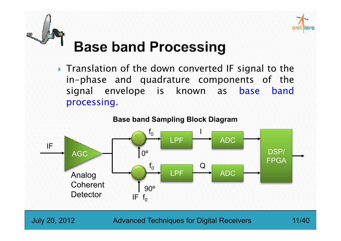
� Translation of the down converted IF signal to thein-phase and quadrature components of thesignal envelope is known as base bandprocessing.
Base band Sampling Block Diagram
July 20, 2012 Advanced Techniques for Digital Receivers 11/40
AGCIF
LPF
LPF
ADC
ADCAnalog
Coherent
Detector IF f0
f0 I
Q
0º
90º
DSP/
FPGAf0
Base band Sampling Block Diagram

� IF sampling, sometimes referred to as directanalog to digital conversion , is another methodof sampling that digitizes the I and Q samplesdirectly.
AGC
AMP
Sample &
HoldADC
AGC Filter
July 20, 2012 Advanced Techniques for Digital Receivers 12/40
DSP/
FPGAIF BPF

� Can yield an improvement in overall SNR by eliminating the analogcoherent detector stage.
� Since the I and Q samples are generated from the same circuitry,there are no phase and gain imbalances between them.
� Only one ADC is required and it must sample at greater than twicethe Nyquist rate.the Nyquist rate.
� The aperture time of the sampling process must be small withrespect to the period of the IF frequency.
� The sample rate must be high enough so that there is no significantdelay between I and Q.
� At the ADC output, an FIR filter is used to interpolate I or Q samplesto obtain time aligned I,Q pairs at the output data rate.
� The accuracy of the estimated I or Q samples is determined by thecomplexity and the coefficients of the FIR filter.
July 20, 2012 Advanced Techniques for Digital Receivers 13/40

� A fundamental part of many communications systems is DigitalDown Conversion (DDC).
� It is a technique that takes a band limited high sample ratedigitized signal, mixes the signal to a lower frequency andreduces the sample rate while retaining all the information.
� Digital receivers often have fast ADC converters to digitize theband limited RF or IF signal generating high data rates; but inmany cases, the signal of interest represents a small proportionmany cases, the signal of interest represents a small proportionof that bandwidth.
� To extract the band of interest at this high sample rate wouldrequire a prohibitively large filter.
� A DDC allows the frequency band of interest to be moved downthe spectrum so the sample rate can be reduced, filterrequirements and further processing on the signal of interestbecome more easily realizable.
July 20, 2012 Advanced Techniques for Digital Receivers 14/40

� The output from the Digital Down converter has retained all theinformation in our frequency band of interest but has moved itdown to base band and so allowed the sample frequency to begreatly reduced.
� This has the advantage of simplifying any further processing on thedata, together with the gains of possibly time shared functionswithin the FPGA due to the lower clock frequency, so allowing morewithin the FPGA due to the lower clock frequency, so allowing moreprocessing to be fitted into the FPGA.
� The lower effective clock frequency will reduce the powerrequirement for the FPGA.
July 20, 2012 Advanced Techniques for Digital Receivers 15/40

� Digital stability – not affected by temperature or manufacturingprocesses. With a DDC, if the system operates at all, it worksperfectly – there’s never any tuning or component tolerance toworry about.
� Controllability – all aspects of the DDC are controlled fromsoftware. The local oscillator can change frequency very rapidlyindeed – in many cases a frequency change can take place on thenext sample. Additionally, that frequency hop can be large – therenext sample. Additionally, that frequency hop can be large – thereis no settling time for the oscillator.
� Size - A single ADC can feed many DDCs, a boon for multi-carrierapplications. A single DDC can be implemented in part of an FPGAdevice, so multiple channels can be implemented or additionalcircuitry could also be added.
July 20, 2012 Advanced Techniques for Digital Receivers 16/40

� ADC speeds are limited - It is not possible today to digitisehigh-frequency carriers directly. There are techniques toextend the range of ADCs, but often it is simpler to useanalog circuits to bring the carrier down to an IF that digitalcircuits can then manage.
� ADC dynamic range is limited - In many communicationssystems, the signal’s amplitude can vary greatly. Fast ADCssystems, the signal’s amplitude can vary greatly. Fast ADCsoften only have 12 bits of resolution – giving an absolutemaximum dynamic range of 72dB. It is often better to useanalog circuits in conjunction with the ADC to implementAGC functions to ensure that this range is best used.
July 20, 2012 Advanced Techniques for Digital Receivers 17/40

Sampling of a signal at the Nyquist rate (sampling rate equalto twice the bandwidth of interest) has the advantage of a lowsampling rate.
� Disadvantages include the need for high-accuracy analog antialiasing circuits to filter the signal before sampling.
� The filter circuits serve to attenuate the high-frequency noise� The filter circuits serve to attenuate the high-frequency noiseand out-of-band components that alias into the signal band(anti aliasing filter).
� These antialiasing filters are vulnerable to noise andinterference that corrupt the signal of interest.
� Also, fine-line VLSI technology is better suited to fast digitalarchitectures rather than precise analog architectures, makingthe filter fabrication process difficult.
July 20, 2012 Advanced Techniques for Digital Receivers 18/40

July 20, 2012 Advanced Techniques for Digital Receivers 19/40

July 20, 2012 Advanced Techniques for Digital Receivers 20/40

� Digital Radio Frequency Memories (DRFMs) are deviceswhich use high-speed sampling and fast digital memoryfor storing and replicating radiating signals.
� They provide the ability to capture radiated emissionsand generate precise, coherent replicas, making themimportant in applications such as signal jamming,important in applications such as signal jamming,deception of covert communications, SIGINT operations,decoys, radar transmitters, simulations and testequipments.
July 20, 2012 Advanced Techniques for Digital Receivers 21/40

High
Analog Filters
BandPassFilter
LowPassFilter
AD CAD CAD CAD C
High
Speed
Dual
Ported
Memory
DAC
LowPassFilter
LO
July 20, 2012 Advanced Techniques for Digital Receivers 22/40
BandPassFilter

� A DRFM can be quite useful in any application whereradiated signals of interest are being collected, routed,and/or generated.
� Some applications include1. Radar signal reception, storage and analysis for1. Radar signal reception, storage and analysis for
ELINT applications (frequency measurements).2. Deception of covert communications (e.g., spread
spectrum frequency hoppers, PSK, FSK).3. SIGINT operations4. Decoy/SAR/ISAR target image synthesis5. Radar transmitter
July 20, 2012 Advanced Techniques for Digital Receivers 23/40

� An exciting newapplication for widebanddigital receivers is calledundersampling, harmonicsampling, bandpasssampling, or Super-sampling, or Super-Nyquist Sampling.
� The concept of discretetime and amplitudesampling of an analogsignal is shown in theFigure.
July 20, 2012 Advanced Techniques for Digital Receivers 24/40
Shannon:Shannon:Shannon:Shannon:� An Analog Signal with a Bandwidth of fa Must beSampled at a Rate of fs>2fa in Order to Avoid the Loss ofInformation.
� The signal bandwidth may extend from DC to fa(Baseband Sampling) or from f1 to f2, where fa = f2 - f1(Baseband Sampling) or from f1 to f2, where fa = f2 - f1(Undersampling, Bandpass Sampling, HarmonicSampling, Super-Nyquist)
NyquistNyquistNyquistNyquist::::� If fs<2fa, then a Phenomena Called Aliasing Will Occur.� Aliasing is used to advantage in undersamplingapplications.
July 20, 2012 Advanced Techniques for Digital Receivers 25/40

� In a receiver which uses direct IF-to-digital techniques (often calledundersampling, harmonic, bandpass,or IF sampling), the IF signal is applieddirectly to a wide bandwidth ADC.
� The ADC sampling rate is chosen to� The ADC sampling rate is chosen tobe at least 2∆f.
� The process of sampling the IFfrequency at the proper rate causesone of the aliased components of ∆fto appear in the dc to fs/2 Nyquistbandwidth of the ADC output.
� DSP techniques can now be used to process the digital base band signal.
July 20, 2012 Advanced Techniques for Digital Receivers 26/40

� This approach eliminates the detector and its associated noiseand distortion.
� There is also more flexibility in the DSP because the ADCsampling rate can be shifted to tune the exact position of the ∆fsignal within the baseband.
� The obvious problem with this approach is that the ADC must� The obvious problem with this approach is that the ADC mustnow be able to accurately digitize signals which are well outsidethe dc to fs/2 Nyquist bandwidth which most ADCs weredesigned to handle.
� Special techniques are available, however, which can extend thedynamic range of ADCs to include IF frequencies.
July 20, 2012 Advanced Techniques for Digital Receivers 27/40

� In broadband receiver applications, one ADC digitizesmultiple channels in the receive path.
� Individual channel selection and filtering is done in thedigital domain.
� Narrowband channel characteristics such as bandwidth,passband ripple, and adjacent channel rejection can bepassband ripple, and adjacent channel rejection can becontrolled with changes to digital parameters (i.e. filtercoefficients).
� Such flexibility is not possible when narrowband analogfilters are in the receive path.
July 20, 2012 Advanced Techniques for Digital Receivers 28/40

� ADCs are generally designed to process signals up toNyquist (fs/2) with a reasonable amount of dynamicperformance.
� However, even though the input bandwidth of asampling ADC is usually much greater than itssampling ADC is usually much greater than itsmaximum sampling rate, the SFDR and effective bit(ENOB) performance usually decreases dramaticallyfor full scale input signals much above fs/2.
� This implies that the selection criteria for ADCs usedin undersampling applications is SFDR or ENOB at theIF frequency, rather than sampling rate.
July 20, 2012 Advanced Techniques for Digital Receivers 29/40

� In the development of classical ADC quantization noisetheory, the assumption is usually made that thequantization error signal is uncorrelated with the ADCinput signal.
� If this is true, then the quantization noise appears asrandom noise spread uniformly over the Nyquistrandom noise spread uniformly over the Nyquistbandwidth, dc to fs/2, and it has an rms value equal toq/√12.
� If, however, the input signal is locked to an non-primeinteger sub multiple of fs, the quantization noise will nolonger appear as uniformly distributed random noise, butinstead will appear as harmonics of the fundamentalinput sinewave. This is especially true if the input is anexact even sub multiple of fs.
July 20, 2012 Advanced Techniques for Digital Receivers 30/40

� The bandpass sigma-delta architecture offers interestingpossibilities in digital receiver area.
� Traditional sigma-delta ADCs contain integrators, whichare lowpass filters. They have passbands which extendfrom DC, and the quantization noise is pushed up intothe higher frequencies.the higher frequencies.
� At present, all commercially available sigma-delta ADCsare of this type (although some which are intended foruse in audio or telecommunications contain bandpassfilters to eliminate any DC response).
July 20, 2012 Advanced Techniques for Digital Receivers 31/40

� In the future, it may be possible to have such bandpass sigma-delta ADCs with userprogrammable digital filter coefficients, sothat the passband of a receiver could be modified duringoperation in response to the characteristics of the signal (andthe interference!) being received.
� Such a function is very attractive, but difficult to implement,since it would involve loading, and storing, several hundreds oreven thousands of 16-22 bit filter coefficients, and wouldconsiderably increase the size, and cost, of the converter.considerably increase the size, and cost, of the converter.
� A feature which could be added comparatively easily to a sigma-delta ADC is a more complex digital filter with separatereference (I) and quadrature (Q) outputs. Such a feature would bemost valuable in many types of radio receivers.
� Technology exists today which should allow the bandpasssigma-delta architecture to achieve 16-bit resolution, SFDR of70 to 80dBc, and an effective throughput rate of 10 to 20MSPS(input sampling rate = 100MSPS, corresponding to anoversampling ratio of 5 to 10). This would allow 40MHz IF with a2MHz bandwidth to be digitized directly.
July 20, 2012 Advanced Techniques for Digital Receivers 32/40

� Superconductor analog-to-digital converters (ADCs) and ultrafast digital circuitry enable processing of microwave signalsentirely in the digital domain.
� A wide variety of continuous-time band pass delta-sigmamodulators using Josephson junction comparators exist.
� Featuring sampling frequencies up to 30 GHz, single-chipdigital receivers have been demonstrated by connecting a rapiddigital receivers have been demonstrated by connecting a rapidsingle flux quantum (RSFQ) digital circuitry with these ADCs.
� These receiver chips, cooled to 4 K by cryogen freerefrigerators, have been used with room-temperature digitalprocessors to demonstrate reception of microwave signals for XBand satellite communications and Link-16 data links.
� To date, the highest frequency of direct digitization is 21 GHz for satellite communication.
July 20, 2012 Advanced Techniques for Digital Receivers 33/40

� The goal of modern radio frequency (RF) receiver systems is to operatesimultaneously in multiple frequency bands and maximize spectrum utilizationwhile supporting diverse modalities, e.g. voice, data, video, and particularly incase of military systems, detection and ranging, and electroniccountermeasures.
� With the advent of software and cognitive radio concepts, there is a growingdesire to bring the flexibility and fidelity of digital processing to the RF domain.
� This, however, requires direct digitization of the received RF signal.
� Radio frequency receivers at the higher end of the spectrum have always had� Radio frequency receivers at the higher end of the spectrum have always hadone or more analog down converters; until recently, no analog-to-digitalconverter (ADC) was capable of directly converting microwave signals.
� A digital-RF receiver, featuring direct digitization followed by subsequentdigital processing, circumvents all the limitations of an analog RF receiverfront-end, enables scalability, agility, rapid reconfigurability, and supportsadvanced waveforms, such as those with fast frequency hopping.
July 20, 2012 Advanced Techniques for Digital Receivers 34/40

� One of the primary advantages of digital processing lies in theability to produce multiple copies without loss of power or fidelity.
� In a digital-RF receiver, multiple, independent chains of digitalsignal processing elements, performing a variety of functions suchas down-conversion, filtering, and demodulation, follow a fast ADC.
Multi-band digital-RF architecture uniquely incorporates RF� Multi-band digital-RF architecture uniquely incorporates RFswitching and distribution in the digital domain, providingprogrammable connectivity between a set of ADCs and a set ofdigital processors.
� Although this digital-RF architecture and all its elements aretechnology-independent, superconductor integrated circuit (IC)technology with Niobium (Nb) Josephson junctions (JJs), currentlyoffer the best solution.
July 20, 2012 Advanced Techniques for Digital Receivers 35/40
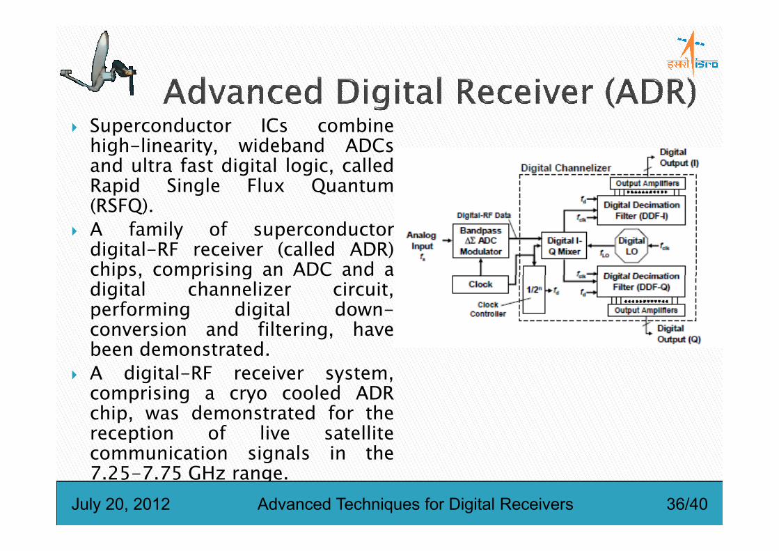
� Superconductor ICs combinehigh-linearity, wideband ADCsand ultra fast digital logic, calledRapid Single Flux Quantum(RSFQ).
� A family of superconductordigital-RF receiver (called ADR)chips, comprising an ADC and achips, comprising an ADC and adigital channelizer circuit,performing digital down-conversion and filtering, havebeen demonstrated.
� A digital-RF receiver system,comprising a cryo cooled ADRchip, was demonstrated for thereception of live satellitecommunication signals in the7.25-7.75 GHz range.
July 20, 2012 Advanced Techniques for Digital Receivers 36/40

� Superconductor ADCs combine comparators with ultra-fast switchingspeed and natural quantization of magnetic flux to enable fast andaccurate data conversion.
� There are various types of superconductor ADCs, including low passphase modulation-demodulation (PMD) and wideband flash ADCs, fordifferent applications.
� Most suited for maximizing signal-to-noise ratio (SNR) in a microwaveband is a band pass delta-sigma (BP∆Σ) modulator.band is a band pass delta-sigma (BP∆Σ) modulator.
� An ideal over sampled delta-sigma modulator of order n, using an m-bitquantizer sampled at fclk, produces a signal-to-noise dynamic rangegiven by
� Whereis the over sampling ratio.
( ) 122
212
12
2
3 +−
Π+
= n
nRm
nSNR
ffR clk ∆= 2/
July 20, 2012 Advanced Techniques for Digital Receivers 37/40

� The modular design methodology ensures that within itsinput-output and heat load capacity, the system can bereconfigured to perform a different function by changingthe chip module and by reprogramming FPGA-baseddigital signal processors.
� The latest (third) generation system (ADR-005), hosting a5×5 mm2 7.5-GHz bandpass ADC chip and an FPGA5×5 mm2 7.5-GHz bandpass ADC chip and an FPGAchannelizer, successfully repeated the over-the-airSATCOM demonstration performed previously using a 1-cm2 single-chip bandpass digital receiver with an on-chipsuperconductor channelizer.
� This system ran error-free for over 12 hours with andwithout a low-noise amplifier.
July 20, 2012 Advanced Techniques for Digital Receivers 38/40

� Implementation using digital building blocksmore towards RF side.
� IF sampling is considered as a reasonablyviable solution.
� Evolution of high speed ADCs enhancedigitization of the input RF itself without downconversion.
� Oversampling techniques� Undersampling Digital Receivers
July 20, 2012 Advanced Techniques for Digital Receivers 39/40

Comments?
July 20, 2012 Advanced Techniques for Digital Receivers 40/40