advanced renal biopsy device with bleeding control mechanism
TRANSCRIPT

UNIVERSITY OF MICHIGAN
Advanced Renal Biopsy Device with Bleeding Control Mechanism
Design Review #3
Team 22, Section 7 Shen Cheok
Andrew Cornieles Matthew Herring
Martin Perrin
11/5/2010
Sponsors
Dr. William Weitzel M.D., University of Michigan Health System Division of Nephrology Dr. Grant Kruger PhD., University of Michigan College of Engineering Department of Mechanical
Engineering
1
Executive Summary In diagnosis of disease, one of the most crucial tools is a tissue biopsy of the afflicted area. Specifically, a minimally invasive needle biopsy can provide a Nephrologist with a kidney tissue specimen containing cells that can be examined under microscope to aid in diagnosis of the kidney diseases. As with all medical procedures, there are risks to the biopsy procedure that the Nephrologist must weigh prior to performing a biopsy. One risk of the kidney biopsy is a bleed from the biopsy site. In practice, bleeding occurs in approximately one third of patients with normal clotting factors. The severity of the bleed dictates the course of treatment for the patient. Remedies for the bleed may range from attempting to pack the biopsy site with hemostatic agents to blood transfusions to nephrectomy and in rare cases the bleeding is so severe that death occurs. To improve patient and biopsy procedure safety, Dr. William Weitzel of the Nephrology department of the University of Michigan Health System has proposed that a biopsy needle be developed that is capable of stopping a bleed at the biopsy site. Furthermore, he has recommended that the use of a hemostatic agent be the method through which bleeding is controlled. The performance of our device was benchmarked against the current biopsy device used, call the BARD Monopty®. We will need a tissue sample volume of 9mm3and needle velocities of 0.9m/s. Additionally, our device must deliver a means of stopping a bleed for repeated biopsies without greatly altering current biopsy practice. The prototype will be an experimental device, to be used strictly in a lab setting. The purpose is not to build a device which is ready to be deployed into the field, but one that will help determine whether or not the approach of deploying hemostatic at the site of the biopsy is a reliable way to reduce bleeding. Using these engineering specifications and the requirement provided by Dr. Weitzel, various concepts were derived using a functional decomposition. These concepts were then analyzed using a Pugh chart to determine the best concept, which was then modified to become the alpha design. The final design uses a similar concept as the BARD Monopty® device, with an inner needle firing first, then an outer sheath firing and cutting and securing a piece of tissue in a cavity in the inner needle. A third stage has been added to deliver a hemostatic through a groove on the opposite side of the inner needle as the cavity, through which a liquid hemostatic will travel. The hemostatic will be deployed at the site of the biopsy. This device will enable the user to alter the amount of hemostatic that is delivered in order to collect as much data as possible regarding the effectiveness of the device. After manufacturing was finished, one sub-component of the device did not work as planed (the clips in the firing mechanism of the needles). Therefore, we were unable to test it using the laboratory setup that we had created as planned. However, we were able to prove that all other sub components of the device functioned properly. Additionally, we were able to get a large enough sample of tissue, and were able to prove that our needle design enabled hemostatic to flow to the hemostatic site. A thorough discussion of challenges with the project along with specific project recommendations are given to best present how further work on this project should be carried out. We thoroughly evaluated every aspect of the project to provide our best hind sight on how to make a vastly more successful product in subsequent design and manufacturing cycles.
2
TABLE OF CONTENTS Executive Summary ........................................................................................................................ 1 TABLE OF CONTENTS ................................................................................................................ 2 1.0 INTRODUCTION .................................................................................................................... 3 2.0 INFORMATION SOURCES.................................................................................................... 6 3.0 ENGINEERING SPECIFICATIONS ....................................................................................... 6 4.0 CONCEPT GENERATION...................................................................................................... 8
4.1 Concept 1 - Rotating Needles: ............................................................................................ 10 4.2 Concept 2 - Channel through inner needles: ....................................................................... 10 4.3 Concept 3 - Channel in needles: ......................................................................................... 11 4.4 Concept 4 - Cavity for solid hemostatic agent: ................................................................... 11 4.5 Concept 5 - Removable inner needle: ................................................................................. 12
5.0 CONCEPT SELECTION PROCESS ..................................................................................... 12 6.0 NEEDLE DESIGN ................................................................................................................. 13 7.0 ALPHA DESIGN.................................................................................................................... 15
7.1 Engineering and Parameter Analysis .................................................................................. 15 7.2 Final Design Description .................................................................................................... 21 7.3 Prototype Description ......................................................................................................... 28 7.4 Fabrication .......................................................................................................................... 29 7.5 Description of Validation .................................................................................................... 33
8.0 DISCUSSION ......................................................................................................................... 35 9.0 RECOMMENDATIONS ........................................................................................................ 39
9.1 Device Specific ................................................................................................................... 39 9.2 Project R&D ....................................................................................................................... 39
10.0 CONCLUSIONS................................................................................................................... 41 11.0 ACKNOWLEDGEMENTS .................................................................................................. 41 12.0 SOURCES............................................................................................................................. 42 APPENDIX A – Bill of Materials ................................................................................................ 43 APPENDIX B – Description of Engineering Changes ................................................................. 43 APPENDIX C – Design Analysis ................................................................................................. 44
C.1 Material Selections ............................................................................................................. 44 C.2 Material Selection Assignment (Environmental Performance) ......................................... 45
APPENDIX D – Engineering Drawings ....................................................................................... 48 APPENDIX E – QFD ................................................................................................................... 61 APPENDIX F – Concept Drawings .............................................................................................. 62 APPENDIX G – Calculation of Volume of Tissue Sample Collection Site ................................. 78 APPENDIX H – Calculation of Tissue Volume Displaced when Performing Biopsy ................. 79

3
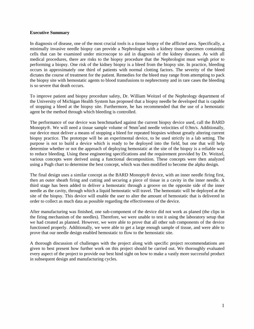
1.0 INTRODUCTION Nephrology, derived from the Greek word “nephros,” meaning kidney, is the study of kidneys. In the medical field, nephrology is a specialty within the field of internal medicine. This specialty focuses on diseases of the kidney and how to diagnose and treat those diseases. A biopsy is a common tool used in the diagnosis of disease. A biopsy is the collection of tissue cells from a site for the purpose of examination. In the case of renal disease, the percutaneous biopsy, or needle biopsy, is a common way to procure tissue cells from the kidney. In a renal biopsy, the cells are collected from the cortex of the kidney. As shown in Figure 1, the cortex has an extensive vascular structure and thus there is a potential for bleeding if some of these structures are cut during the biopsy procedure. The actual method of taking a biopsy today is to use ultrasonogaphy to guide the biopsy needle to the renal biopsy site while the patient lies in a prone position.
Figure 1: Anatomy of Kidney
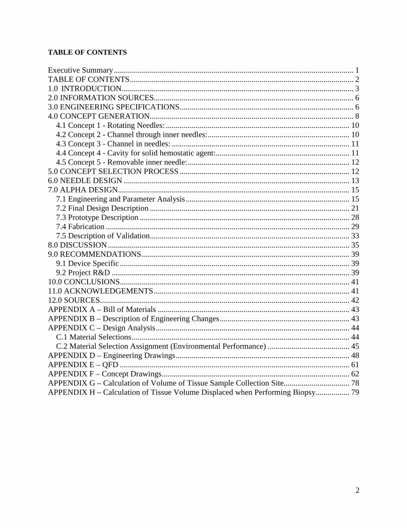
Unfortunately, approximately 30% of renal biopsies have bleeding complications. The treatment of these bleeds ranges from applying hemostatic agents, to blood transfusions, to even open surgery depending on the severity of the bleed. The complications can range from the patient developing hematomas, as shown in Figure 2, around the kidney, to hematuria, a nephrectomy, or in rare cases patient death. With this complication rate, doctors must weigh the risks of the procedure with the benefits of the information it may yield. Thus, it is desirable to look for a method to prevent bleeding at the biopsy site at the time of the procedure.
4
Figure 2: Renal Hematoma
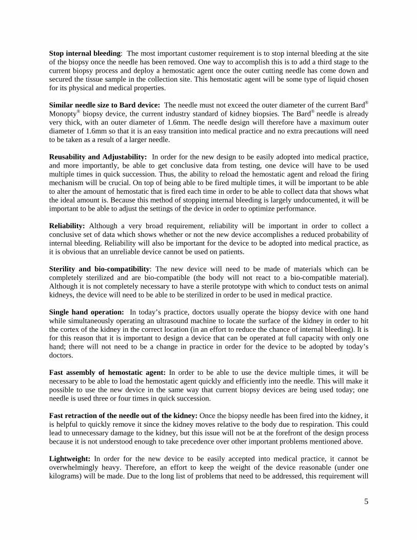
Dr. William Weitzel M.D. and Dr. Grant Kruger of the University of Michigan have sponsored this project’s effort to address bleeding complications resulting from the renal needle biopsy procedure. The goal of this design process is to develop a biopsy needle that can mitigate potential bleeding complications at the biopsy site without altering common medical practice. This project will develop a novel biopsy needle device for the kidney that adds a third stage to the standard biopsy process - deploying a hemostatic agent to control bleeding at the site of the biopsy. Through consultations with Dr. Weitzel and Dr. Kruger, the formation of a set of customer requirements upon which to base the design were established. These requirements are listed below as well as summarized in Table 1. In the table, each requirement has been weight ranked to differentiate the importance of each of the requirements. The weight is rated on a scale from one to ten, with ten being the most important. This device will be meant to be used in an experimental setting to determine if deploying a hemostatic is a useful way to prevent internal bleeding. Therefore the device will have much more adjustability for the user to find the ideal operating conditions.
Table 1: Customer Requirements ranked in order of importance Customer Requirement Weight Stopping internal bleeding 10 Similar needle size to Bard® device 9 Reusability and Adjustability 9 Reliability (testable prototype) 8 Sterility and bio-compatibility 7 Single hand operation 6 Fast assembly of hemostatic agent 5 Fast retraction of needle out of kidney 3 Lightweight 3 Low cost 2
5
Stop internal bleeding: The most important customer requirement is to stop internal bleeding at the site of the biopsy once the needle has been removed. One way to accomplish this is to add a third stage to the current biopsy process and deploy a hemostatic agent once the outer cutting needle has come down and secured the tissue sample in the collection site. This hemostatic agent will be some type of liquid chosen for its physical and medical properties. Similar needle size to Bard device: The needle must not exceed the outer diameter of the current Bard® Monopty® biopsy device, the current industry standard of kidney biopsies. The Bard® needle is already very thick, with an outer diameter of 1.6mm. The needle design will therefore have a maximum outer diameter of 1.6mm so that it is an easy transition into medical practice and no extra precautions will need to be taken as a result of a larger needle. Reusability and Adjustability: In order for the new design to be easily adopted into medical practice, and more importantly, be able to get conclusive data from testing, one device will have to be used multiple times in quick succession. Thus, the ability to reload the hemostatic agent and reload the firing mechanism will be crucial. On top of being able to be fired multiple times, it will be important to be able to alter the amount of hemostatic that is fired each time in order to be able to collect data that shows what the ideal amount is. Because this method of stopping internal bleeding is largely undocumented, it will be important to be able to adjust the settings of the device in order to optimize performance. Reliability: Although a very broad requirement, reliability will be important in order to collect a conclusive set of data which shows whether or not the new device accomplishes a reduced probability of internal bleeding. Reliability will also be important for the device to be adopted into medical practice, as it is obvious that an unreliable device cannot be used on patients. Sterility and bio-compatibility: The new device will need to be made of materials which can be completely sterilized and are bio-compatible (the body will not react to a bio-compatible material). Although it is not completely necessary to have a sterile prototype with which to conduct tests on animal kidneys, the device will need to be able to be sterilized in order to be used in medical practice. Single hand operation: In today’s practice, doctors usually operate the biopsy device with one hand while simultaneously operating an ultrasound machine to locate the surface of the kidney in order to hit the cortex of the kidney in the correct location (in an effort to reduce the chance of internal bleeding). It is for this reason that it is important to design a device that can be operated at full capacity with only one hand; there will not need to be a change in practice in order for the device to be adopted by today’s doctors. Fast assembly of hemostatic agent: In order to be able to use the device multiple times, it will be necessary to be able to load the hemostatic agent quickly and efficiently into the needle. This will make it possible to use the new device in the same way that current biopsy devices are being used today; one needle is used three or four times in quick succession. Fast retraction of the needle out of the kidney: Once the biopsy needle has been fired into the kidney, it is helpful to quickly remove it since the kidney moves relative to the body due to respiration. This could lead to unnecessary damage to the kidney, but this issue will not be at the forefront of the design process because it is not understood enough to take precedence over other important problems mentioned above. Lightweight: In order for the new device to be easily accepted into medical practice, it cannot be overwhelmingly heavy. Therefore, an effort to keep the weight of the device reasonable (under one kilograms) will be made. Due to the long list of problems that need to be addressed, this requirement will

6
be considered, but it is possible that the prototype will not meet it because of the difference between prototyping materials and production materials. Low cost: Although it will be difficult to estimate the precise cost of a new mass produced device, an effort will be made to avoid unnecessary expense and favor lower cost solutions. However, a more expensive solution which produces superior results for the above requirements will be chosen over a low cost solution with inferior performance. 2.0 INFORMATION SOURCES To design an advanced biopsy needle with bleeding control poses many unique challenges. These challenges fall into two major categories. The first category is technical challenges. Technical challenges arise from trying to achieve the engineering specifications. These challenges may be in conflict with each other so design optimization may be required. These challenges are often overcome by creative design and innovation and by also applying engineering practices to the problem at hand. The second category is device-patient interactions. These challenges prove much more difficult to describe as they often have many variables and are poorly understood. For example, to determine needle dynamics the fact that tissue is heterogeneous and visco-elastic must be considered. Optimal needle tip and cutter geometries must be considered. The amount of local force required to cut the tissue should be determined. How much needle bending occurs and how that relates to friction within the needle must be asked. Determining the proper hemostatic and volume of that hemostatic is unknown. As a consequence there are two options in addressing these questions. A series of experiments to estimate these values using arbitrary design elements can be performed. The second option is to recognize that the current device works for taking a biopsy. Taking the latter route and benchmarking the current device allows us to have a high level of confidence that the device will work. This allows the designing process to move forward and permits optimization of the device as there will be better data supporting the design changes. In terms of what hemostatic, it is dependent on how the patient bleeds and risks associated with each method of hemostasis. Here again studies can shed light for the subject on the initial design and then be included in subsequent design iterations. Thus, it was chosen to benchmark the current Bard device to develop the basic engineering specifications. To address what hemostatic to use Dr Weitzel voiced his concerns regarding types of hemostatic agents. In summary he asked to either use a solid, or a solid with a pro coagulant or the thickest flowable hemostatic. There are a myriad of hemostatic agents on the market today, and there are risks associated with them all. To address this problem we contacted Dr. Chris Sonnenday, an abdominal transplant surgeon at UMHS. He recommended that we use SURGIFLO or Gelfoam with topical thrombin to achieve hemostasis as they are both techniques used in the operating room at the hospital. A technical challenge that we have been investigating is the manufacturing of the prototype since the scale of the project is quite small. A variety of processes to achieve the desired design dimensions have been investigated. The expertise of Bob Coury, Roland Chen, and other faculty and staff at the university to obtain possible manufacturing methods of the needles for the project has been requested. 3.0 ENGINEERING SPECIFICATIONS The engineering specifications are imperative in helping to design the Alpha prototype. To determine engineering specifications in a well defined and quantitative manner, thorough literature research, interviews with couple of doctors, and experimental testing on the BARD device. Most of the engineering

7
specifications determined are benchmarked against the BARD device have been done. The engineering specifications are also mapped up from the customer requirements and can be seen in appendix D. The engineering specifications are needle dimensions/geometry, mass of device, friction between needle and tissue, needle stiffness, spring constant, volume of hemostatic agent needed, volume of tissue collecting site, and velocity of the outer needle. Needle Dimensions and Geometry: The needle geometry is rated the most important engineering specification in the QFD. It will determine the amount of force needed in cutting the kidney tissue, effectiveness in delivering the hemostatic agent, the injuries caused on the kidney and volume of tissue collected. Since it is rated the most important feature, most of the design focus is given to this feature. However, given the limited time to produce a prototype, the decision was to have the same outer needle geometry as the BARD needle. This decision is based on multiple experiments on kidney-like ballistics gel in the lab. Good shearing from the mechanism of the ballistics gel during experiment was observed. Also, from the customer requirements, designing a needle that has a larger needle diameter than the BARD device was unacceptable. The geometry and dimensions of the BARD needle are measured using a certified caliper. Friction between Needle and Tissue: Due to the complexity in determining the friction between needle and tissue and the variation of tissue between humans, the team has decided to get an overall tissue friction based on experimental result done by a masters’ student in Mechanical Engineering, Mainak Mitra. This number will help the team in determining the optimized force to fire the outer needle for cutting the kidney tissue. Needle Stiffness: Needle stiffness is another factor in determining the force required to fire the outer needle. It depends on the material property and is quantified in the Young’s Modulus. If a soft needle is inserted in the kidney, the deflection of the needle will injure the surrounding kidney tissue and prolong the time in performing biopsy. Based on this, the decision was to design the needle out of metal. A lower limit of 180GPa is desired in this case. The new needle will have the same second moment of inertia as the BARD device at its weakest point, the tissue collection site. Spring Constant: The spring constant determines the force actuated on the outer needle. The force actuated is proportional to the spring constant and to the distance of spring compressed. Depending on the amount of space available for the spring to be compressed, the spring constant could vary. However, it should not be too large or too small until it affects the dimensions of the handle. Volume of Hemostatic Agent: The hemostatic agent needed depends on the tissue displaced during the insertion of outer and inner needle in the kidney. Depending on how far the operator placed the first position of the inner needle, the volume of tissue displaced in the kidney would vary. Thus, it is better for a design of the mechanism that can manipulate the amount of hemostatic agent accordingly. It was determined that the function of the volume of hemostatic agent needed to be 2.14y where y is the distance travelled by the needle. This calculation can be found in the Appendix D. Volume of Tissue Collecting Site: The volume of the tissue collection site needs to be at least 9.012mm3. This result is based on the calculation done on the BARD device. The decision was to go not less than that value after speaking with Dr. Weitzel. A lower volume collecting site might cause the operator to perform the biopsy twice due to insufficient tissue samples collected and it is obviously not preferable. The calculation of this value can be found in the Appendix E. Velocity of the Outer Needle: The velocity profile of the outer needle was obtained after speaking with Mainak Mitra. The maximum velocity of the BARD device is 0.87m/s. This value will determine the tissue cutting mechanics. Again, the decision was to have the similar velocity profile to the BARD device

8
after looking at the satisfying results of the BARD device. Figure 3 shows the graphs which were used to get the velocity data.
Figure 3: Data used to find desired needle velocities
4.0 CONCEPT GENERATION In order to generate an Alpha concept, the decision was to make a functional decomposition chart to help identify the key functions and sub-functions that the biopsy device must accomplish. This exercise, along with thorough brainstorming was the main technique used to generate a variety of concepts ranging in all aspects of price, feasibility, and conventionality. The purpose of this section is to walk through the process in detail and describe some of the main concepts that were considered. Functional Decomposition – Figure 4 shows the result of the functional decomposition exercise. The functional decomposition was important because it helped identify the inputs that went into the biopsy device, the main functions of the device, as well as the key sub-functions.

9
Figure 4: Functional Decomposition Chart
From this figure, it is easy to see that the main functions of the biopsy device are to remove tissue from the kidney, and to deploy a hemostatic agent at the sight of the biopsy. While these two functions were obvious from the start of the project, the sub-functions and the inputs were not as trivial and are much easier to see after having gone through the process of the functional development. The inputs for the whole device are the patient (and specifically the kidney and the surrounding tissue), the actions of the doctor, the stored energy in the device, and the hemostatic agent. These inputs were identified in the problem definition portion of the project. While all of these inputs need to be considered for the hemostatic deployment function, the hemostatic agent input is not important for the tissue removal function of the device. The sub-functions are where the real brainstorming took place. For this part of the concept generation, the main functions were broken down into simpler functions that involved a portion of the desired inputs and outputs. The first sub-function of the tissue removal is a firing of the inner needle. This sub-function will get tissue into the main cavity of the needle (which a sub-function of the inner needle firing). The following sub-function of tissue removal is the outer needle firing, which will cut the tissue that is in the cavity and secure it in place when the needle is removed. During this, while this sub-function is happening, it is important that the doctor get some feedback that the outer needle had fired so that there is some confirmation that the tissue is secure in the needle cavity. The last sub-function of the tissue removal is the positioning and removal of the needle in and out of the kidney. This sub-function is important to insure that the biopsy has been taken in the correct location of the kidney (the cortex), and that the needle is removed quickly to lessen the risk of unnecessary tissue tearing. Deployment of the hemostatic agent also has a few sub-functions associated with it. In order for the hemostatic to be deployed at the site of the biopsy, the agent must be stored somewhere in the device. Therefore, a hemostatic storage function is necessary in the device. A sub-function of this sub-function is the load of the hemostatic agent into the storage area of the device. This is important in order for the device to be used multiple times in a single procedure. The other sub-function of hemostatic deployment

10
is a delivery mechanism for the hemostatic agent. In order to get the agent at the site of the biopsy, there must be some method of getting the agent out of the device and into the kidney. A helpful sub-function of this sub-function would be some sort of feedback that the hemostatic agent has been delivered. Using the information derived from the functional development, a few main concepts were derived. These concepts are illustrated and discussed in the following sections. Each concept was made to focus on some or all of the functions and sub-functions from the functional development; some with more success than others. All of the original concepts can be found in the appendix. 4.1 Concept 1 - Rotating Needles: The rotating needles concept is based on using a liquid hemostatic agent which is pre-loaded in the needle before the procedure begins. The entire needle assembly is inserted in the kidney, with the cavity for tissue already exposed. The doctor then releases the outer needle which cuts the tissue, then releases the hemostatic through a channel in the inner needle. Figure 5 below shows needle assembly, with the inner needle showed as dashed lines. The outer needle would rotate around the inner needle but would not translate relative to the inner needle.
Figure 5: Rotating Needle Concept
A major advantage of this method is that it allows for a more precise location of the biopsy, because the needles are staying in place during the entire process, so there will be no unexpected bleeding if the needles start in the cortex of the kidney. However, rotating needles would be a completely new concept for the medical community and would not be easily accepted into medical practice. Also, as is discussed in the following concept, a channel through the inner needle is very impractical. 4.2 Concept 2 - Channel through inner needles: This concept is based on using a liquid hemostatic and deploying it through a channel which goes through the inner needle. It uses the same cutting mechanics and needle motion as the Bard device, with similar spring loaded needles. The doctor places the needles just outside the cortex of the kidney, fires the needles to collect the tissue sample, and then deploys the hemostatic agent through the channel in the inner needle. The figure below shows the channel in the inner needle.
Figure 6: Channel through the inner needles
One of the advantages of this is that it does not alter the current medical practice at all. The procedure would be almost identical to what is currently being done. It would also be very easy to reload the needle for multiple uses. However, because of this channel to deploy the liquid hemostatic is there, the cavity for tissue must be shallower, and therefore longer to collect an adequate sample volume. It is also extremely difficult to manufacture a through hole in a needle of this diameter and length.

11
4.3 Concept 3 - Channel in needles: This concept is similar to concept 2 expect that instead of the channel being through the inner needle, it is simply ground into the inner needle and outer needle, so it looks more like a groove in both needles than a through hole in the inner needle. The figure below shows the channel at the bottom of the inner needle. This channel would be used to push a liquid hemostatic down the channel and into the biopsy sight once the outer needle has fired and cut the tissue sample from the kidney. In the figure below, the channels in the inner and outer needles are visible. In both this concept and concept 2, the hemostatic would be stored in the handheld section of the device.
Figure 7: Channel in Needles
One of the advantages of this design is that, as in concept 2, it does not alter medical practice and makes it easy to deploy liquid hemostatic at the site of the biopsy. This concept would also be much easier to machine than concept two while leaving the possibility of a large cavity size for the tissue. However, there are a few drawbacks: it is still difficult to machine a groove in the inner needle, and even more difficult to machine a groove on the inside of the outer needle. 4.4 Concept 4 - Cavity for solid hemostatic agent: This concept is based on using a solid hemostatic agent, which is preloaded in the needles prior to each use of the device. A channel in the inner needle makes way for a protrusion in the outer needle to push out the hemostatic once the inner needle has been fired, and the outer needle fires after. The figure below illustrates the concept, showing the two needle assembly on the left and a cross section of the outer needle on the right side.
Figure 8: Cavity for solid hemostatic agent
The main advantage of this design is that is uses a solid hemostatic, like GELFOAM, which can not only stop bleeding with a clotting agent, but also stop bleeding mechanically by simply clogging the hole that the biopsy leaves behind. However, machining the outer needle would be very difficult, and deploying the hemostatic before the cutting of the tissue would not work with certainty. Another disadvantage is that it would be very hard to reload the solid hemostatic in between each use, making the device unlikely to be easily integrated into current medical practice.
12
4.5 Concept 5 - Removable inner needle: The removable inner needle concept aims to provide use with the maximum space possible to deliver the hemostatic to the biopsy site. The uniqueness of this idea is to use the outer needle as the delivery pathway to the biopsy site. This concept most often takes the form of a gun bolt mechanism. In theory, the inner and outer needle would start in the loaded position. Then, the user would trigger the inner needle into the kidney, and the motion of the inner needle would trigger the outer needle to close into place just as the BARD device does. Next, the inner needle would rotate 180 degrees to keep the specimen in the biopsy device, and the inner needle would retract further back along the length of the device. As the needle retracted past a given point the hemostatic could be introduced into the “barrel” of the device through a “breach.” Depending on the type of hemostatic chosen the inner needle could then return down the “barrel” of the device to push a solid hemostatic into the outer needle as the outer needle retracts. The inner needle could remain out of the outer needle and a liquid hemostatic could be deployed down the “barrel”. Drawing this concept proves difficult as it is more sequence driven than packaging or geometry driven. It is best to think of this concept as that of a rifle; the inner needle as the bolt, the hemostatic entry point as the breach, and the outer needle as an “elongating and retracting” barrel. This concept focuses more on the design of the mechanism that moves the needles. It allows transition away from having to fabricate extremely small features and deliver a wide variety of hemostatics. The primary drawback of this is how to develop a mechanism that can reliably perform this task in less than 1 second. 5.0 CONCEPT SELECTION PROCESS In order to select the best process, a quantitative analysis was used to compare all of the concepts to each other. From this data, the best concept was selected and then slightly modified so that all of the design criteria were maximized. In the previous section, the main advantages and disadvantages were described for each of the main concepts. This section will discuss how those advantages and disadvantages factored into the selection process. Pugh chart: The method that was chosen to show the quantitative analysis that was performed to select the best concept was the Pugh chart. The Pugh chart, which is shown in Table 2, compares all the concepts to each other with respect to the selection criteria, which are the top seven costumer requirements. The weight of the selection criteria is the weight of the customer requirements divided by ten for more reasonable analysis. The rating that each concept received was a number from one to five, five being the best and one being the worst.

13
Table 2: Pugh Chart
From the Pugh chart above, it is clear that concept 3 is the best concept. This concept offers the best performance in all of the selection criteria. The criteria in which it out performs the other concepts the most is reliability (testable prototype), because it is the only concept that can be feasibly manufactured (although still difficult because of the small scale of the needle). This concept enables the deployment of a hemostatic, and the easy removal of tissue from the kidney. These are the two main functions from the functional decomposition. It also accomplishes all of the sub-functions, and does not alter current medical practice. After analyzing of the results from our Pugh chart, the advantages and disadvantages of all the concepts, it was obvious that concept 3 was the best concept for this project. Concept 3 also provides the best chance of accomplishing all of our engineering specifications, included needle volume, tissue cavity volume, needle velocities, and deployment of the hemostatic agent. The main difference between this concept and the others is that it allows the tissue cavity volume to be much greater, which is very important because it enables the doctor to get an adequate sample and greatly improves the reliability of the device (a major costumer requirement). The only changes to the concept were due to the fact that it did not score perfectly. Thus, some changes were made to it in the alpha prototype phase. The most important change is the removal of the channel in the outer needle. This change was made to make the device easier to manufacture and make it more reliable. Even with this change, concept 3 will still be very difficult to manufacture, which will be the major challenge moving forward. For more details on the device, please see the following section on the alpha prototype. 6.0 NEEDLE DESIGN After revising the engineering specifications thoroughly, The main needle design challenge is to come up with a way to deploy hemostatic agent in a confined inner needle geometry. Thus, the main focus is on the inner needle design. A design was needed that had an inner needle that will deliver the hemostatic agent and collect the tissue sample at the same time. The alpha design will have the same tissue collecting sample site size and similar needle tip geometry (cutting angle) as the Bard® Monopty® biopsy device. (Figure 9)

14
Figure 9: A zoom out picutre of the inner needle geometry.
It was decided to construct a channel underneath the inner needle in order to deliver the hemostatic agent during biopsy. (Figure 10) The semicircle channel functions as a smooth guide for the hemostatic agent from the handle to the kidney. It extends from the needle tip all the way down to the handle.
Figure 10: Hemostatic agent travel channel
The needle design collects tissue sample via trapping and cutting the tissue sample in the tissue collecting site. The kidney tissue will quickly extend or fill up the tissue collecting site in this step. The sharp edges of the outer needle will cut through the tissue that stays in the tissue collecting site. Finally, the hemostatic agent is deployed. The duration between needle firing should be fast enough to minimize the injury on the kidney. The hemostatic agent will quickly fill up the wound cavity and react with the blood expanding to stop bleeding at the biopsy site. The whole process will take about one to two seconds and is diagramed below.
Outer needle
Inner Needle
Channel and hemostatic agent travel direction

15
Figure 11: Inner needle was injected into the kidney
Figure 12: Outer needle is fired up and cut through the tissue that stays in the tissue collecting site.
Figure 13: Hemostatic agent is released and quickly reacts and fills up the wound in the kidney.
7.0 ALPHA DESIGN 7.1 Engineering and Parameter Analysis To develop a new biopsy needle capable of delivering a hemostatic to the biopsy site primarily concern is with areas of the mechanical engineering undergraduate curriculum. In the product design statics and mechanics of materials, dynamics, and fluid dynamics must be considered. Since the design is not predicated on the transfer of thermal energy, thermal sciences may largely be ignored. At this time the current alpha prototype is envisioned as spring loaded disposable device that has very few operation cycles to perform during its usable life. Depending on the outcome of the engineering analysis and
Kidney
Hemostatic agent
Kidney
Kidney

16
expected performance of the current alpha prototype the changes to the prototype may require the device to become an “investment” piece of hardware where material failure modes must be considered. Additionally, it is assumed that simple dynamics suffice to generate the proper response of the system. However, test and design modifications may require to better model the system and consider the system response to the applied forces. Statics Problems: Simple static analyses of parts experiencing large forces or that have attachment conditions will be performed. To accomplish this the use of free body diagrams to identify forces and then determine resultant forces at critical loading points was implemented. Stiffness of Beam Problems: In the course of designing the new biopsy needle geometry, the current stiffness of the BARD Monopty® biopsy device’s inner needle must be maintained. The fact that the force acts normal to the needle point surface as shown in Figure 14 was assumed.
Figure 14: Force Diagram
From the cross-section view above the second moment of areas Ix and Iy can be determined and Ixy can be neglected due to symmetry. Using Equation 1 the maximum stress σzz can be determined. Assuming simple bending, this equation reduces to Equation 2.
𝜎𝑧𝑧 = �𝑀𝑥𝐼𝑦+𝑀𝑦𝐼𝑥𝑦�𝑦−�𝑀𝑦𝐼𝑥+𝑀𝑥𝐼𝑥𝑦�𝑥�𝐼𝑥𝐼𝑦−𝐼𝑥𝑦2�
(Eq. 1)
𝜎𝑧 = 𝑀𝑦
𝐼 (Eq. 2)
The σzz determined from the Monopty® inner needle design for the load then can be used to back-calculate the necessary needle dimensions to maintain stiffness. The use of the parallel axis theorem can accomplish this. To limit the equations to generate a singular solution and not a matrix of solution the width and depth of the channel required to deliver the hemostatic must be determined.
Channel Design Flat Design
Figure 15: Potential Inner Needle Geometries
Point Traverse Load P
Needle Cross-section

17
The flat design may be approximated as a simple rectangular or trapezoidal cross-section for analysis. The channel design will be decomposed in to a rectangular section with two partial circular sections. This method of analysis may also be used if clips or other compliant mechanisms or attachments are used in the biopsy needle mechanism design. However these problems will likely reduce to simple beam bending and displacement problems that are based on energy inputs that create the proper motion. System Energy and Dynamics: To meet the benchmarked targets for needle velocities, simple rigid body dynamics and Newton’s Laws are applied. Where “m” is the mass of the needle and attached components and “a” is the acceleration required to meet the velocity requirements in the given firing/insertion distance of the inner and outer needles. The use of energy methods, K.E.=.5mv2, if energy is stored in the mechanism. At this time the effects of tissue interaction and friction in system are neglected by providing a performance factor to the calculated requirements (ie. force, acceleration, velocity). Fluid Dynamics: In the flow of a hemostatic to the biopsy site the appropriate steady state mass/volume flow rate of the incompressible fluid hemostatic agent must be determined. Once determined the required flow rate of the hemostatic agent can be used to determine the appropriate pressure to apply to the fluid flow. This is a function of backpressure, viscosity, and delivery path geometry. The flow rate will be determined at this time by the fact that the hemostatic agent must fill the volume of space being vacated during needle retraction. From this volume flow rate Bernoulli’s equation can be used to solve the necessary pressures that apply. Gravity is neglected in this analysis as the fluid is moving over a trivial distance. Bernoulli’s Equation (P = pressure, ρ = density, v = velocity of flow, γ = specific gravity)
𝐶𝑜𝑛𝑠𝑡𝑎𝑛𝑡 𝐴𝑙𝑜𝑛𝑔 𝑆𝑡𝑟𝑒𝑎𝑚𝑙𝑖𝑛𝑒 = 𝑃 + 12𝜌𝑣2 + 𝛾𝑧 (Eq. 3)
Volume Flow rate (Q= Vol. Flow Rate., A= Cross-sectional area, v = velocity of flow)
Q=A*v (Eq. 4) Pressure Drop (ΔP=Pressure Drop, λ= Friction co-efficient, ρ= density, w = flow velocity)
∆𝑃 = 𝜆 × 𝐿𝐷
× 𝜌2
× 𝑤2 (Eq. 5) While this analysis should provide appropriate data regarding the necessary design parameters of design, validation in an experimental test setup will yield the best drivers for design changes as effects of the biopsy process are not entirely understood at this time. Thus, the problem identification and design changes will have to be proposed following some initial testing. Manufacturing at this scale also proves to be very difficult so the dimensions required to theoretically succeed in this design exercise may prove too difficult to create in reality. Snap Fit/ Bending Problem Analysis: Snap fit mechanism is implemented in our design. The snap fit mechanism will enable us to eliminate the need for complex fixtures and to translate linear motion easily. In the design, a pair of clips is needed to release the compressed spring when activated by the push button. The amount of force needed, deflection of the clips and suitable materials for the clip are the parameters to be determined in this analysis. In the snap fit connection,

18
Figure 16: Snap fit with parameter
h=height of the clip b=base width of the clip L=length of the clip F=deflection force exerted on the clip E= Young’s Modulus of material To calculate the deflection of the clips, we first write the deflection of a beam equation, a,
𝑎 = 𝐹𝐿3
3𝐸𝐼 (Eq. 6)
then using the second moment area of a rectangular beam,
𝐼 = 𝑏ℎ3
12 (Eq. 7)
we write
𝐹 = 𝑎𝐸𝑏ℎ3
4𝐿3 (Eq. 8)
Then, plugging in different value of Young’s Modulus into the expression we were able to determine the different deflection force needed. The results obtained are shown below:
Table 3: Deflection Force Analysis Material Young’s Modulus (Mpa) Deflection Force (lbs) Aluminum 6064 69000 37.0 Delrin 2800 1.5
As seen in table, the deflection force needed for Delrin is about twenty times smaller than the force needed for Aluminum. A smaller value of force is preferable in our design because it will ensure the snap
F

19
fit mechanism will work and also minimize the energy needed to actuate the released mechanism of the spring. Inner Needle Cross Section in Electrical Discharge Machining (EDM) Analysis: The stiffness of the inner needle’s tissue collection site is one of the important factors that we need to determine. An electrical discharge machining is needed to make the channel for delivering the hemostatic agent and the tissue collection site. This machining process will highly affect the stiffness of the needle because the tissue collection site is very thin and it will have a channel on the opposite. (Figure 17)
Figure 17: Cross section view of the inner needle
To ensure the needle’s stiffness remains the same as the stiffness of the BARD device after making the channel underneath, we need to reduce the volume of the tissue collection site. The volume of the tissue collection site is determine by y, as shown in figure. The amount of volume reduce is calculated using the definition of second moment of area Iy below,
𝐼𝑦 = ∫𝑥𝑦 𝑑𝐴 (Eq. 9) Second moment of area is used here because it affects the stiffness of the needle. To determine the centroid of the cross section, we measured and get the geometry of the cross section and plug it into the definition of centroid,
𝐶 = ∑𝐶𝑖𝐴𝑖∑𝐴𝑖
(Eq. 10)
Then, using Mathematical to simulate both equations, we determined y to be 0.68mm.
Pressure of Hemostatic Deployment Analysis: We used Bernoulli equation to calculate the amount of pressure needed to deploy the hemostatic agent into the kidney. Since the prototype is designed to accommodate a huge variety of hemostatic agent, we will use a highly viscous hemostatic agent as the higher limit for the density of liquid in the equation. Several assumptions were made to simplify the calculation; the system is assumed to be in steady state, the liquid is incompressible and there is no turbulence flow in the system. The governing equation for the delivering the hemostatic agent is,
𝑃ℎ = (𝑃𝑏ρb+ vb
2
2 + vh2
2 )ρh (Eq. 11)
Ph : Pressure of Hemostatic Deployment Pb : Blood Pressure
channel for hemostatic agent
tissue collection site y

20
ρh : Hemostatic Density ρb : Blood Denisty vh : Velocity of deployment vb : Velocity of blood flow From the equation above, we can calculate the force needed, F to create that amount of pressure, Ph,
𝑭 = 𝑃ℎ A
(Eq. 12) where A is the area of the E&R plate. Spring Constant and Needle Velocity: Using the fact that the force exerted by the spring of the BARD device is able to cut through the kidney tissue, we obtained the spring constant from a master student, Mainak Mitra. From the spring constant K=810.4N/m we calculate the force, F exerted by the BARD device to be 17.8N from the equation,
𝐹 = 𝑘𝑥 (Eq. 13) where x is the needle displacement. Then, using the same equation and the displacement on our prototype, we determine the spring needed. Safety Factor of Clips: To calculate the safety factor, we used Solidworks Simulation to perform simple Finite Element Analysis on the clip to ensure they do not fail. By applying F=1.5lbs that we calculated earlier on the clips and making the end of the clips fixed, we obtained the stress concentration figure. (Figure 18)
Figure 18: Stress Concentration Plot on the clip
As seen in the figure, the maximum stress occurs at the end of the clips. The safety factor is calculated using equation,

21
𝑆𝐹 = 𝑦𝑖𝑒𝑙𝑑 𝑠𝑡𝑟𝑒𝑛𝑔𝑡ℎ
𝑚𝑎𝑥𝑖𝑚𝑢𝑚 𝑠𝑡𝑒𝑠𝑠= 99𝑀𝑝𝑎
45𝑀𝑝𝑎= 2.2 (Eq. 14)
The safety factor of 2.2 is sufficient enough to allow any unexpected loads, misuse, and emergency situations. 7.2 Final Design Description The final design, as shown in Figure 19, is designed with the engineering specification previously derived and with rapid machining in mind. In this section we will break down the device into major component sections with sub-parts’ general geometry and function discussed in detail.
Figure 19: Final design
Housing Components: The housing is comprised of four unique parts that enclose the mechanical function of the device. In short, the house is designed to enclose the mechanical parts of the device while leaving the user able to access the vital parts of the biopsy device. Starting at the top of the device, the Top Plate is the upper most part of the housing components as shown in Figure 20. The Top Plate is has three main geometric features. The plate has four drilled holes that allow assembly to the side housing components with ¼ -20 bolts. The next geometric feature is the large center hole. This milled hole is designed to allow the release button to protrude the the exterior of the device and allow the user to actuate the mechanism. To allow for machining simplicity the hole is square with properly radius corners to allow for using a single ¼ end mill bit and provide clearance to the release button. Finally, the exterior dimensions represent the maximum length and width of the mechanism housing.

22
Figure 20: Housing Components
The two most substantial components of the housing are the side housing components. The housing sides provide the most critical components of the housing design. The two sides of the housing comprise the two largest parts in the device and have the highest mass in the device. The side house contains the all of the moving components and provides stability to the device. It also guides and aligns all of the moving components and permits them to translate only in the desired vertical motion. The housing is also designed to be the stationary parts on which the springs will exert their reacting force when under compression. The exposed slots on the device permit the user to disengage the inner needle to be released so that the biopsy specimen can be examined. The housing is also vital in the performance of the compliant clips in our design. The housing sides have locations for the clips to engage with the two needle pistons and have attachment points for the clips required to retain the retraction plate. The two side plates also have ¼-20 taped holes for attachment to the Top Plate and the Bottom Plate. These eight bolting location should provide sufficient coupling between all of the housing components. If in the event this method of housing assembly is insufficient to maintain proper of internal alignment of the moving parts there is sufficient space within the side walls of the housing to allow up to four cross connecting bolts to improve the alignment of the device.

23
Figure 21: Housing system
The Bottom Plate makes up the final component of the housing system for the biopsy device. The plate similar to the Top Plate is designed to create a bottom surface for the device as well as provide a surface for the 3rd release spring to load on until released. The shape of the Bottom Plate can be seen below along with the guide hole for the inner and outer needles.
Figure 22: Housing base plate
Release Button: The release button, shown below, starts the firing process of the biopsy device by transferring force from the user to the compliant clips of the inner needle housing causing them to elastically deform allowing them to release from the housing surface. The design of the button is such that it can quickly be manufactured and modified in the event that difficulty is encountered in with achieving the desired performance of the compliant clips.

24
Figure 23: Release button
Inner Needle Piston Components with Compliant Clips: The Inner Needle Piston with clips is comprised of five parts of which four are unique pieces. For the device to function properly, the inner needle must be released from its nominal position and translate along the vertical axis to the biopsy position. Upon collection of the tissue specimen the needle must be retracted. After returning to the nominal position there must be a way to disengage the needle from the spring force and clips to collect the specimen. To accomplish these tasks, we developed the Inner Needle Piston with the geometry see below.
Figure 24: Piston components
First examining the Inner Needle Piston casing illustrated above, the casing has three critical functions. The upper surface of the casing is a point of contact between the 1st release spring and the housing. The upper portion of the casing has milled grooves to accept the compliant clips. The threaded 1/8th inch through holes provide the means of carrying the load between the clips and casing. The next feature of the casing is the ½ inch dia. bored hole from the bottom of the casing. This cavity creates space for the Inner Needle Piston carrier as illustrated above. The casing has the square channels to accommodate the arms

25
from the carrier. The casing’s remaining geometry is driven by stability, packaging constraints, and leaving surfaces that will interfere with the lower compliant clips causing them to release. The needle carrier featured above on the right may be developed as a single solid component or two simple components attached with a screw and it has two simple functions. The first function is to provide and attachment point for the inner needle. This is accomplished through a small bored hole for the inner needle and the utilization of a set screw to keep the needle in place. The second function is to provide the user a way to disengage the inner needle from the casing and reload the retraction plate after firing. Finally the clips that attach to the casing hold the spring in compression until being released by the user depressing the button. Outer Needle Piston Components with Compliant Clips: The Outer Needle Piston Components with clips is comprised of two main components. The outer needle casing, shown below, has very similar functions to the inner needle casing with a few key differences.
Figure 25: Individual Pistons
The casing is the interface between the needles and the hemostatic agent injection point. The housing accepts the hemostatic through a hole drilled in the side of the casing that cuts through the outer needle. The location of the port for the hemostatic is crucial to hopefully avoid leaks into the device through carefully controlled tolerances. The outer needle casing again provides stability and alignment to the needles and a place for the 2nd release spring to act against. Expel and Retraction Plate with clips: The E&R, show below, is designed as a single component that may be manufactured in numerous different ways. The E&R plate has two functions as the name implies.

26
Figure 26: Retraction Plate
The primary function of the plate is to expel the hemostatic from the storage syringe loaded in by the user. The secondary function of this plate is to simultaneously retract the outer and inner needle. This simultaneous retraction and expelling of the hemostatic is designed to control the rate and timing of the hemostatic injection with the retraction of the needles. The E&R plate shown below is guided by tracks in the side housing elements of the biopsy device. The device is initiated by the collision of the outer needle casing with the compliant clips. The compliant clips retaining the E&R plate are mounted to the housing through taped and drilled holes in the housing sides. Needles: The biopsy device has two needles. These needles are very similar to those found on the BARD Monopty device with one critical exception. The inner needle has a channel machined on the back of needle to provide a pathway for the hemostatic to reach the biopsy site. The channel depth was selected such that we would achieve minimal losses to stiffness of the inner needle at the biopsy site. The inner needle is shown below as to illustrate the location and relative size of the biopsy site and the hemostatic channel.
Figure 27: Needle design
Release Springs: The biopsy device has three springs that make the device operational. There are two springs of stiffness of 4.5lbs/inch that when released from their compressed positions extend 22mm causing the translation of the inner needle first and sequentially the outer needle. The third spring is considerably stiffer at approximately 27lbs/inch. This high stiffness is a consequence of having to achieve static equilibrium at the extended position of the return 3rd release spring.
27
Biopsy Device Operating Sequence:
1. To prime the device the user must first prime the needle channel by forcing hemostatic through it so displace the air in the channel reducing the risk of air emboli.
2. The user must ensure that the Inner Needle is securely in the firing position by visually examining that the needle carrier arm is in the front of the device.
3. The user then must place the desired hemostatic in the firing chamber in a syringe withdrawn to the desired length.
4. The user must then grip the device such that their digits are clear of the external and internal moving arms.
5. The user will then depress the Release Button. 6. The release button will translate downward the vertical axis of the device due to the force applied
from the user. 7. The release button will engage the first set of compliant clips and due to the force applied from
the user it will cause the clips to deflect due the bending moment caused by the force applied through the button.
8. Upon the clips deflecting sufficiently far enough to clear the clip-housing interface the compressed 1st release spring will elongate while applying force to the inner needle casing and thus the inner needle carrier and inner needle. This force will accelerate the needle as it translates down the vertical axis of the device a distance of 22mm.
9. At the completion of translation the inner needle casing will interfere with the second set of compliant clips to deform from the force applied by the inner needle casing.
10. As the second set of clips deflects sufficiently far to clear the housing, the 2nd release spring will elongate while applying for to the outer needle casing and thus the outer needle. This force from the 2nd release spring will accelerate the outer needle as it translates down the vertical axis of the device a distance of 22mm. The outer needle will cause tissue local to the biopsy collection site to experience sheer forces that will leads to the ultimate tensile failure of the tissue causing it to separate from the biopsy tissue.
11. At the completion of translation of the outer needle casing, the casing will interfere with the E&R plate clips causing them to deflect as the other compliant clips had.
12. After the proper deflection, the 3rd release spring will engage driving the E&R plate up the vertical axis of the device causing the 1st and 2nd release spring to compress and returning the inner and outer casing back to the nominal positions. It will simultaneously expel the hemostatic as the plate will depress the syringe plunger forcing the hemostatic into the needles.
13. To collect the biopsy specimen the user must rotate the inner needle carrier arm 90 degrees to disengage it from the inner needle casing and then depress the E&R plate so as to reload the mechanism while simultaneously providing access to the biopsy tissue.
Below is a graphic of the sequence described above.
28
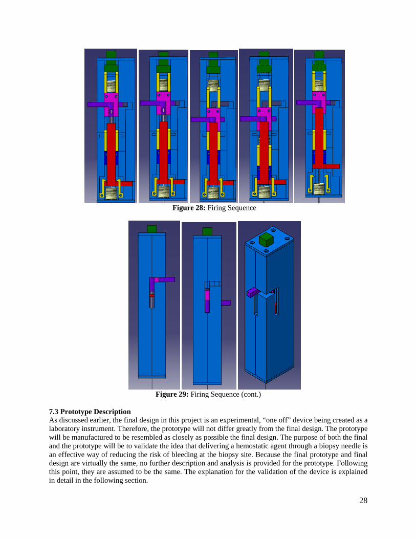
Figure 28: Firing Sequence
Figure 29: Firing Sequence (cont.)
7.3 Prototype Description As discussed earlier, the final design in this project is an experimental, “one off” device being created as a laboratory instrument. Therefore, the prototype will not differ greatly from the final design. The prototype will be manufactured to be resembled as closely as possible the final design. The purpose of both the final and the prototype will be to validate the idea that delivering a hemostatic agent through a biopsy needle is an effective way of reducing the risk of bleeding at the biopsy site. Because the final prototype and final design are virtually the same, no further description and analysis is provided for the prototype. Following this point, they are assumed to be the same. The explanation for the validation of the device is explained in detail in the following section.

29
7.4 Fabrication Machining and Materials: For the purposes of this prototype the materials that were used are 6061 Aluminum and Delrin. These two materials were chosen for ease of fabrication and appropriateness of design needs. Because this device is for experimental use the selected materials used in the prototype do not need to be used for a mass produced device. The two machining processes that were used are an electric discharge machining (EDM) process and a milling process. These two processes removed material from the stock acquired to create the individual parts. These two processes were chosen for the speed at which the parts can be fabricated. Also, they allow for the appropriate dimensioning necessary for each of the parts. Other options were looked at for machining but rapid prototyping and hard grinding were determined to have too many issues with the appropriate dimensioning and strength. All of the engineering drawings can be found in appendix D. Inner needle: The fabrication of the inner needle was done using a wire EDM process. Using this process a groove of 0.4mm in height was cut away down the length of the needle as shown in Figure 26. Specifically, this groove was cut from the tip of the inner needle up to the point where the outer needle sheathe is secured into its piston. This process was chosen because it provides the best option for fabricating the groove dimension needed for this mechanism’s design. A picture of the setup of on the EDM machine is shown in figure 30(a).
Figure 30 (a): EDM machine setup (b):Sheet metal tool and custom vice with needle
In order to create the channel, a piece of sheet metal with thickness 0.4mm was used as the “wire,” or the tool in the EDM machine. The needle as secured in a custom made vise, which enable the needle to be worked on without it bending or deforming in any way. This device was made by taking a piece of aluminum and milling a groove with a depth of 1mm for the needle to be placed in, and 2 matching smaller pieces to be placed on top of the needle and bolted down to secure the needle which the machining was happening. This device can be seen in figure 30(b). Needle sheathe: The fabrication of the outer needle sheathe was done using a simple cutting process. The length was determined by the total length from the needle sheath’s end to the retracted position of the needle sheath’s piston. Cutting from the non-cutting end was chosen so that only needle length needs to be addressed in the fabrication of this part thereby making sure no process needed to be carried out to re-fabricate the cutting end of the sheathe. Inner needle sled: The inner needle sled was created using aluminum stock. This stock was milled out to create the part shown on the right of Figure 24. The important tolerances for this part are the through-hole diameters.

30
Inner needle and Needle sheathe pistons: The inner needle and needle sheathe pistons were created using aluminum stock. The stock was milled out to create the parts shown on the left side of Figure 24. The dimensions of these pistons were set to allow for the springs to be able to move on the outside of them forcing the pistons Retraction plate: The retraction plate was made out of aluminum and was machined using the water jet machine. This enabled precise machining without much user input and a quick turnaround time. The water jet machine was very helpful in the later stages of manufacturing since it enabled us to work on other critical components while just one person was supervising it. This part was later broken into two pieces, the retraction plate bottom and retraction plate top for ease of machining. For details about this and all other changes made to the design during manufacturing, please see appendix E Removable firing clips: The removable firing clips were created in pairs using Delrin®. These pairs were created in large quantity to allow for multiple replacements during testing. Therefore, the pairs were cut from a long group of the clips. The Delrin® was cut into these groups using a milling process. The purpose of this choice is to allow for good compliance of the clips for our firing purposes. The reasoning behind creating many of them is both for ease of fabrication and for allowance of testing problems associated with clips failing. Device housing: The outer housing shown in Figure 21 was made from Aluminum. Because of time constraints, and the importance of precise machining of these parts, they were outsourced to First Cut, a CNC prototype company in Maple Plain, Minnesota. The dimensioning for this part was crucial to allow for the motion of the spring and the pistons within itself. The inside surface finish of these parts was also crucial to allow for the sliding of the parts within the device. Assembly Plan The assembly of the device was one of the simpler parts of the project. Figure 31 shows all of the parts of the device laid out on a table top, including all of the machined parts and all of the purchased parts. Table 4 is a key to the drawing, explain which part is associated to each number.

31
Figure 31: All parts of alpha prototype
Table 4: Key to Figure 31
Part Number Part Name 1 Right Housing 2 Top Plate 3 Retraction Spring 4 Outer Needle 5 Retraction Plate Bottom 6 Inner needle spring 7 Out Needle Sled 8 Retraction Plate Top 9 Inner Needle(through spring in this picture) 10 Inner Needle Piston 11 Inner Needle Sled 12 Firing Clips 13 Syringe Adapter 14 Left Housing 15 Bottom Plate 16 Button 17 Syringe 18 Outer Needle Spring 19 Arm
First, attach the firing clips in place in the housing and the inner and outer needle sleds, as they are in Figure 31. In order to assemble the device, one must start assembling with the retraction plate top, part 8. Place the outer needle spring on top of the outer needle sled, which should already have the outer needle

32
in it. Then take the retraction plate bottom and enclose the sled and the spring within the retraction plate top and bottom, with the syringe adapter hole in the outer needle sled facing the same way as the protrusion in the retraction plate bottom. Once this is done, place the inner needle in the inner needle piston, and insert the inner needle piston in the inner needle sled. Then press the inner needle through the whole in the retraction plate top, and through the hole in the outer needle sled. At this point, these parts should look as they do in figure 31. Place this entire unit in the matching slot in the left housing. Then slide the retraction-spring around the outer needle and carefully slide the bottom plate around the outer needle and secure the outer plate to the left housing with the appropriate screws. Put the button in the matching whole in the top plate, and secure the top plate to the left housing using the appropriate screws. Once this is complete, place the inner-needle-spring between the inner-needle-sled and the button, as shown in figure 32. At this point, the alpha prototype should look like figure 32, with the only step remaining being to simple place the right house on top of the left house and secure the top and bottom plates to the right housing. Once this is complete, the prototype is fully assembled and should look like figure 33.
Figure 32: Alpha prototype assembled but left open
Figure 33: Alpha prototype fully assembled

33
7.5 Description of Validation In order to test that our device has met all of our engineering specifications, a few steps were taken, first ensuring that the device actually works, and then ensuring that the performance is on par with the engineering specifications. The table below shows the tests that will be performed in order.
Table 5: List of validation tests conducted Step Test Purpose
1 Testing Setup Determine if testing setup properly simulates kidney 2 Fire device in air without hemostatic Determine if needles fire in order 3 Fire device in air with hemostatic Determine hemostatic is delivered through the needle 4 Fire device into ballistic gel Determine if device removes “tissue” and clogs a hole
The first step in our testing was to determine if we could achieve a manufactured bleed using our testing setup. The setup, shown in figure 34, allowed us to facilitate blood flow through a block of ballistics gel. The gel acted as a phantom kidney for our experiment, allowing us to pump water at pressure through manufactured cavities which acted as veins for our purposes. The testing setup was successful. We could achieve a manufactured bleed and this allowed us to perform multiple test without the need of bovine kidneys.
Figure 34: Testing Setup
The next step was to see if the needles fire in sequence, with the inner needle firing first, and then the outer needle firing. Because of the mechanics of the device, the only way for the outer needle to fire is for the inner needle to fire and release it, so if the outer needle fires when we fire the device, both needles

34
have fired in sequence that step is a success. Unfortunately, due to the non-compliance of the clips, the needles would not fire in succession without manually releasing each set of clips. While this was a partial failure it still succeeded in its operation with manual firing of its clips. The third step in this process was to see whether or not the device is able to deliver a hemostatic agent through the needle during the biopsy process. This was accomplished by loading the device with hemostatic and firing it as would be done in a biopsy procedure, but into the air instead of into a solid. This makes it easy to see whether or not some hemostatic is coming out, and because there was not any blood pressure at the tip of the needle, the device is less likely to fail than if it were fired into a solid. This was a successful test and a picture is shown below.
Figure 35: Delivering hemostatic
Next a stimulation of a biopsy needle accidentally hitting a vein or an artery during the procedure. A block of ballistic gel was fitted with a soft tube running through it. A pump which replicates blood flow (both in pressure and a beating stimulation) was hooked up to the tube so that there is essentially an artificial vein running through artificial tissue. The device was loaded and fired into the ballistic gel, puncturing the tube. The test determined if a piece of ballistic gel was lodged in the tissue cavity and removed from the block. This test was successful in that it achieved our goal of removing “tissue” at the site of the biopsy. A picture is shown below.
Figure 36: Capturing Tissue
If compliance was achieved with clips further tests would be possible. The fifth part of our validation process would have been undertaken. This fifth part would be to hook up a bovine kidney to the same pump used in step four. This will provide a transfused kidney that the device can be fired into. An ideal

35
result in this test would be to constituent tissue samples (in size) and have no bleeds. However, there is really no way of know whether or not bleeds would have resulted from the BARD device, so the results of this test will be slightly inclusive in that regard. The main goal of this test is to see whether or not the device functions properly when used on a real kidney (tissue removed, hemostatic delivered). 8.0 DISCUSSION Design Critiques and Recommendations In this section, we will organize a critique of our project into first some global comments on both the design and manufacturing of the prototype device. We will then critique the some of the major design concepts/systems and then we will discuss individual components and their respective design and manufacturing considerations. Finally, we will also critique our validation testing. Following each critique section, we will provide recommendations for improvements based upon each critique. Overall project recommendations will be address in following major section. Global Design Commentary: By examining our design requirements and engineering specifications our primary goal was to achieve Bard Monopty biopsy performance and then introducing a haemostatic agent at the biopsy site during retraction of the biopsy needles. Bard Monopty performance is defined by device size, biopsy sample size, needle velocity, needle size and stiffness, ease of use, status indicator, and reliability of operation. These performance characteristic along with the design goal of deploying a haemostatic agent at the biopsy site are a mixture of functional requirements and packaging requirements. Consequently, our final design required high tolerances parts to function in a minimal amount of space. For expediency and ease of manufacturing based upon available resources our components were given square or rectangular geometry. In a production device or a device with higher budget a circular device would be a more ideal choice. Global Manufacturing Commentary: Given the design requirements, we required very accurate and high tolerance parts for our design. Additionally, the size of the parts design made manufacturing very difficult. Given the budget, facilities, and time available for completion of this project, it proved very difficult to achieve the exact specifications of each unique part while remaining on our manufacturing schedule. We also developed a manufacturing method for our needle channel design using an EDM machine. This fabrication process required experimentation to determine the best methodology to achieve the desired feature on the needle. Spring-Compliant-Clip Concept/Systems Critique: The spring and compliant clip design we had is a valid method storing and releasing energy in a sequential manner. It is cheap and reliable method of firing the needles. This system can easily be disposed of or sterilized for future use. However, this system has its drawbacks. It requires that all of the parts fit well together and that every component is functioning as designed. It also does not allow for adjustability in the sense that new springs and housing clearances need modified to swap out for off the shelf springs. Designing clips that release as required also requires significant engineering and even some trial and error. Spring-Compliant-Clip Concept/Systems Recommendations: For truly global markets this is the most promising and cheapest method of achieving a biopsy and deploying a haemostatic. Springs are also extremely compact, which makes them ideal for a hand held hand powered device. We would recommend that after careful selection of a haemostatic and gaining knowledge about the interactions between the needle, tissue, and haemostatic that any type of power source be used for the device to establish a working prototype.

36
Haemostatic Delivery Concept/Systems Critique: The concept of delivering the haemostatic down a channel located on the back of the needle is a novel way to help control biopsy bleeds. Of the methods of delivering a haemostatic to the biopsy site while the inner needle is still present in the outer needle, we feel this has the most promise. We had difficulty achieving robust seals to deliver the haemostatic. Other methods of creating space for haemostatic deployment may be possible with clever mechanism design. Haemostatic Delivery Concept/Systems Recommendations: This concept of haemostatic delivery shows promise. However, a robust examination of the possibility of removing the inner needle after the sample is collected while the outer needle remains in place is required. Also new biopsy needle designs should merit further exploration as they may provide additional pathways for the haemostatic to flow. Given the development time of ME 450 deviations from the BARD design proved too risky to explore given other design challenges. Inner Needle with Channel Critique: The concept of delivering the haemostatic down a channel located on the back of the needle is a novel way to help control biopsy bleeds. It allows us to maintain most of the biopsy needle stiffness at the biopsy collection site and overall volume of the biopsy collection site. The major drawbacks to this method of delivery are the extremely small space allocated to the flow of a haemostatic or a working fluid to eject a solid haemostatic at the needle tip. Additionally manufacturing of this channel proved extremely difficult. Inner Needle with Channel Recommendations: To further refine this design, a true optimization of the needle channel size as compared to the stiffness of needle at the biopsy sample site and the size of the biopsy collected must be performed. Additional manufacturing methods must be examined to determine the optimum channel making technique that results in the best surface finish to facilitate flow. For EDMing of the channel a method must be developed to better control uniform channel depth straightness. Additional channels or varying channel depths or widths should be further examined. Retractions Concept/Systems Critique: Our spring loaded retraction concept shows a method of a controlled retraction of the needles and expelling a haemostatic as the needles exit the biopsy site. The major drawback is the very large force required to accomplish this. The retraction spring when compressed has exerted a force of approximate 40lbs. This force proves extremely hard to load to the spring and the vibrations from the violent retraction may have unforeseen consequences. Retraction Concept/Systems Recommendations: For a non-externally powered device, this spring is the only method of achieving a controlled needle retraction and deployment of haemostatic. In our device the retraction method reloads the device and that requires a very stiff spring. In the previous device the needles and haemostatic were retracted but the device had to be taken apart to reload it. This design is more likely to be successful in the clinical setting if a novel way of accessing the needles is achieved as well as a simpler method of reloading the device. Release Button Critique: The release button was designed to extend out from the housing of the device as to provide the user with adequate clearance to depress the button. The button has a traverse distance of 1/8th in. to release the clips to Trocar needle carrier. Our design made the button square for ease of manufacturing. However, the engagement surface at the bottom of the button was machined with the designed geometry to create a right angle at the clip engagement point. This design was flawed as the force from the user depressing the button caused a binding condition with the release clips instead of displacing the clips allowing them to release. Our manufacturing process did meet the necessary tolerances for the clip engagement portion of the button thus causing insufficient displacement of the clips to allow the clips to release.

37
Release Button Recommendations: Most critically, the button clip interference must be redesigned to cause the button release and not bind on the release clips. A simple way to avoid a binding condition would be to provide additional clearance for the deflection of the clip as the button engages as well as adding a chamfer, a mirror the chamfer used on the clip mirrored about an axis parallel to the interference surface, to the button interference surface to avoid creating a point load. Additionally, the protrusion length of could be reduced for increased aesthetics and reducing the devices overall length. A new button may also move to a rounded geometry as to reduce any sharp points on the button surface. A new button design may include a return feature such as a spring or an elastic region material that will return to its nominal shape after deformation. A newly manufactured button must be manufactured to the drawing’s specifications and most critically the interference condition at the clip button interface. Release Clip Critique: Our release clip design was based upon the idea that with adequate interference and applied force that the compliant clips would release each subsequent stage in the biopsy device. The clips were designed to be replaced in the device should they fail or fail to perform as expected. This idea was good as it will allow further trouble shooting of the device in the future. The material we used to manufacture the clips was also had a higher modulus of elasticity resulting in the thickness of the clips to be manually be reduced along with an un anticipated lack of force being applied by the releasing feature. We also questioned the reliability of the compliant clips and chose to use four clips to retain each stage prior to release. While this decision was based upon safety and reliability of retaining the loaded device, it also proved to provide additional points of failure in the release of the device. This along with imperfect manufacturing caused the clips not to perform to the desired design. Release Clip Recommendation: To improve clip performance, a future re-design should aim to improve the performance of each individual clip while attempting to reduce the overall number of clips as that reduced the number of failure points. To re-design these clips, one should consider the tensile force applied to each clip and the bending moment applied by the reaction force at the holding surface. The moment on the parts holding the clips should be calculated so as to ensure that the spring loaded parts so not bind in the slot. The interference face angle should be adjusted to reduce the likelihood of a binding condition so a slip condition occurs at the surface. Additionally the holding surface area of each clip should be minimized to as to facilitate ease of release. However, this minimization of surface area will cause the friction between the surfaces to rise because of increased normal forces applied by the spring that this relationship must be optimized. Needle Firing Springs Critique: The springs used to fire our needles provided adequate force and energy storing capability. Our springs were 33% stiffer than the previous teams. The major downfall of our spring selection was that we were unable to buy springs to our exact specifications. Consequently, we bought spring that we were forced to cut, stretch, and grind to achieve our desired performance. Due to fact the springs in compression were not always stable because of manufacturing and seating in the device the springs did not compress perfectly vertically. While we did not validate the needle velocity because of overall performance problems, we feel confident that if improved manufacturing methods were used friction would be reduced and the springs would perform to specification. Needle Firing Springs Recommendations: Ideally, custom cut and ground spring of the right stiffness and length and compression length could be purchased. Additionally, as a modification of the parts directly on either end of the spring could be either attached, perhaps via weld or screws, or at the very least have a seat ground for the spring. To improve stability of the spring in compression if improved manufacturing of the spring is insufficient, a small solid rod could be placed in the center of the spring attached to the holding surface to keep the spring aligned. Inner Needle (Trocar) Carrier Critique: Our square inner needle carrier had several good design aspects. First, the ability to swap in and out different clip designs or new clips if they break allows the
38
device to be usable beyond the life or design of each clip. The needle carrier also allow the needle sled to have a slip fit condition with the inner needle sled that required no physical attachment between the two as the inner needle sled cylinder fit within the cylindrical bore. As with the release button the interference and forces between the carrier and the subsequent release clips cause a bind to occur. Inner Needle (Trocar) Carrier Recommendations: Along with accurate machining of the final part within tolerances, the interference between the release clips must be redesigned to ensure the clips will release when the device is fired. The needle carrier should also have a seat specifically machined to ensure a proper alignment of the spring. Additionally this part needs to have the anterior arm bar path Inner Needle Sled Critique: The inner needle sled functioned as designed. It fit with the inner needle carrier and was able to hold the inner needle. The milled groove for the arm bar also performed as specified and it allowed us disengage the inner needle. Inner Needle Sled Recommendations: A redesign of this part should include a better attachment method to the arm bar. Currently, a slip fit is all that holds the needle. A magnet or a screw attachment is desirable. Additionally, the needle sled should attempt to increase the area of its base to increase stability for reloading the retraction spring. Outer Needle (Cannula) Needle and Needle Sled Critique: The outer needle was a direct design copy of that found on the BARD device. As such, it requires no further redesign. However the outer needle carrier block was a novel design. During validation testing we showed that it was possible to port a haemostatic into the block and pass it down the back side of the needle. The method of sealing the haemostatic in the block by creating a high tolerance fit between the inner and outer need was insufficient to direct the majority of the haemostatic flow to the base of the needle. Outer Needle (Cannula) Needle and Needle Sled Recommendations: The block concept is one viable method introducing the haemostatic to the channel. However, if this method is reused in future designs, a better sealing method must be used. Likely a piston with o-rings will be required to create a more robust seal. Additionally the needle groove must be further refined to reduce flow resistance. The current flow connect also largely obstructs the haemostatic deployment arm which should be redesigned to make a more accessible site to load the haemostatic. An alternative method of delivering the haemostatic would be to use a compressible tube between the inner needle and outer needle similar to the neck of a flexible straw. Retraction Plate and Spring Critique: The design of the retraction plate and spring shows promise. During validation we were unable to fully test its viability as the retaining clips lacked sufficient strength to retain the fully compressed retraction spring. The spring was of the correct stiffness to accomplish the desired retraction. In hindsight, the spring is not a feasible means of retraction in its current design. A secondary mechanism must be constructed to give the user sufficient force to re-compress the spring. Retraction Plate and Spring Recommendations: Retracting the needles is a necessary part design, as we must control the timing and location of the haemostatic deployment. In spring powered designs, a design consideration must weigh the decision between having a secondary mechanism to reload the device or to disengage the needles from the driver springs and retract the needle and deploy the haemostatic. In non-spring powered versions of this device, any number of methods may be employed to retract the needles and deploy the haemostatic. Validation Testing Critique: Our validation set-up provided a unique way to validate our biopsy device. It allowed use to validate the ability to biopsy a ballistics gel specimen and guarantee that a bleed

39
will occur when a biopsy is completed. It also avoids having to use a bovine kidney model. This test set-up also allows the user to tune the ballistic gel veins to simulate a wide variety of flow conditions. Validation Testing Recommendations: We recommend that this set-up be maintained. It provides a repeatable and reliable way to test biopsy devices. The biggest change is not so much on the device but on the tuning of device to best replicate human kidney biopsy bleeds. 9.0 RECOMMENDATIONS Our recommendations are broken down into two major sections: Those recommendations specific to our device not previously discussed in the previous section and those recommendations pertaining to the overall project goal of developing a biopsy device able to deliver a haemostatic at the biopsy site. The recommendations that are device specific are meant to be areas of improvement that should our device be a model for future designs, that these additions will help it arrive in the clinic sooner. We also felt it was important to discuss how a rigorous research and development process might go to yield a highly successful clinical device. This was done because both our device and the previous device have not resulted in highly usable devices. 9.1 Device Specific These recommendations are based upon the goals of our project. Therefore, they are not all inclusive to all future design attempts for a clinical device. Recommendations on the general project goal of to how to achieve a clinical grade device are located in the project section below. Improved User Feedback: Our device currently has only the arm bar on the needle sled to indicate that the device is loaded and has fired. Additional means of determining that all of the subcomponents and systems are fully ready and functional on the device should be developed to indicate to the user that the device is functioning as desired. Reloading Mechanism: Conceptually our device’s reloading mechanism worked. We did have a method for loading in new needles and reloading a variety of haemostatic agents. However, this area still requires some further refinement. The method of disengaging the needles was awkward and it was almost impossible to compress the retraction spring. An auxiliary device should be considered to reload the device and disengage the needle between each biopsy. 9.2 Project R&D This project is extremely complex. The following is a suggested list of experiments and research that could help improve future designs and optimize current design ideas. This overview level design of experiments assumes that time and budget are no object, but rather we wanted to focus on how an extensive R&D process could be carried out to design the ideal device. Each research topic/experiment would require further development and design. These experiments may also lead unforeseen new experiments. Conceivably, each experiment could be carried out in the course of a semester as part of any number of mechanical engineering curriculum classes. Biopsy Needle Geometry Experimentation: This exercise is designed to prove potential alternative biopsy collection methods. Alternative biopsy needle designs can be validated on bovine or chicken breast model. Validation will come from viability of sample collected for pathological analysis and forces required to obtain sample. Other considerations should include damage to surround tissue and needle size. During this experimentation, manufacturing considerations should be addressed as well as how haemostatic (execution not required) could be delivered given specific needle geometry. For example, in

40
our project we attempted to keep the BARD needle design. To deploy a haemostatic based on that design, we had two major choices: A channel or hole bored down the trocar needle or to remove the needle entirely and use the cannula as a pathway to deliver the haemostatic. All needles should be benchmarked against the BARD Monopty® device. Biopsy Bleed Characterization Research: To improve the phantom test set-up, an analysis of a potential range pressures and flow rates of bleeds should be conducted in concert with a nephrologists or surgeon. This refinement of data will allow the phantom test set-up to be scaled or tuned to more realistically represent bleeding characteristics. This characterization is crucial as it will later influence haemostatic selection research. Needle Size Selection Research: Examine, using bovine kidney model, the likelihood of biopsy bleed based upon needle size. For example, how much does the risk of a bleed increase based upon needle size. Given the tight space requirements, it is desirable to maximizing needle size without disproportionately increasing the risk of biopsy bleed or other medical complications (infection, damage to surrounding tissue, kidney damage from impulse force exerted on the kidney, healing time, etc.) not foreseen by increasing needle size. Haemostatic Selection Research: Using the phantom kidney set-up determine which haemostatic has the highest probability of causing haemostasis given a range of kidney pressures and needle track sizes. This testing should consider form of the haemostatic and “acceptable” combinations of haemostatics. This testing should be carried out with standard hollow needles. A method of capturing emboli that might form as a consequence of haemostatic deployment should be set up to allow a risk assessment of the haemostatic causing “floating” emboli. The focus should be on volume of haemostatic required normalized to characteristics of the needle track (length, diameter, volume). From the volume data, tables of injection rates can be compiled based upon diameter of needle and desired injection time using. Additionally, a threshold for maximum volume flow rate can be determined as the point where the working fluid would cause tissue damage (think like a water jet). Once establishing the necessary volume of haemostatic required to stop a bleed, it should be checked for biological and toxicity problems with consultation from a physician. Finally, standard electro-embolization or cauterization should be evaluated as a methodology of achieving haemostasis by examining the estimated time required. Again here, local tissue damage should be assessed as a consequence of this method of achieving haemostasis. All haemostatics need scored in a QFD diagram with other considerations such as price, availability, easy of storage, shelf life etc. Needle/Deployment Optimization Research: Based upon the four previous experiments, design and build a testing fixture capable of testing different combinations of feasible haemostatics and biopsy needle designs. This test set-up should focus evaluating and validating both the haemostatic deployment and the ability of the needle to collect a biopsy sample. Size of the mechanism and power resources should not be a factor. This experimentation should include both bovine and chicken breast models as well as the ballistic gel phantom. The results of this research should help future designers understand problems with delivering the haemostatic to and through the needles as well as experimentally determine/verify tissue-needle-haemostatic interactions. It will also serve as test platform for mechanism design. Device Design I: At this point, the design of the device should focus improving the testing fixture to allow for rapid reload and biopsy ability. Sterilization, environmental impact, and cost for markets should start to be considered. While the fixture was originally designed for data collection and idea validation, it should now be used as a test bench for different mechanism components given that design of how the biopsy is obtained and how the haemostatic is deployed should largely be resolved or at the very least optimized from the previous research. Packaging and weight at this point should not be a consideration. The goal of this phase is to validate individual level components and sub-systems.

41
Device Design II & III: In this final stage of device development, all of the sub-components and systems should have been validated. The goal of this project phase should be to package all of the working components and consider what a clinical version of the device might look like. Any modifications of previously tested sub-systems can be carried out on the test set-up. In the context of ME 450, a first prototype should be completed by DR3 so troubleshooting can occur before design expo. Device design iteration three should take knowledge gained from final product of first full design attempt and make any further modifications necessary to develop a clinical grade device. Any major design changes can quickly be validated on the test bench set-up from the needle optimization research or on the previous first attempt at a clinical device. These device iterations should result in a product capable of meeting market demands. 10.0 CONCLUSIONS Since bleeding is a common risk in the kidney biopsy procedure, Dr. Weitzel has requested our team to develop a novel experimental biopsy device that can control bleeding from the biopsy site. The design process for the biopsy needle is completed and an alpha prototype has been developed. This alpha prototype will enable the delivery of a liquid hemostatic agent down the needle of the biopsy device and will help lessen the chance of internal bleeding during the biopsy procedure. It is the opinion of this group that with the recommendations presented and design critiques realized a re-completed prototype would allow for successful operation of the advanced renal biopsy device.
11.0 ACKNOWLEDGEMENTS Our team would like to acknowledge the assistance and contributions of multiple people over the course of this project.
• Dr. William Weitzel of the UMHS, Sponsor, for his continued support over the course of this project. His involvement and assistance has been invaluable.
• Dr. Grant Kruger, Sponsor, for his direction and help in coordinating this effort over the course of this project.
• Prof. Sienko, for design review feedback • Dan Johnson – Course GSI • Bob Coury – ME Shop

42
12.0 SOURCES Patents: Gambale RA, Shah, CB, Weiser MF, Forcucci SJ, Forde S. Agent delivery systems. U.S. Patent No. 7,232,421 B1. June 19, 2007. Gambale RA. Tissue capturing and suturing device and method. U.S. Patent No. 7,220,266 B2. May 22, 2007. Haaga JR. Biopsy system with hemostatic insert. U.S. Patent No. 5,487,392. January 30, 1996. Haaga JR. Hemostatic sheath for a biopsy needle and method of use. Patent 4,838,280. June 13, 1989. Haaga JR. Medical biopsy needle. U.S. Patent No. 5,080,655. January 14, 1992. Krause WR. Biopsy and delivery device. U.S. Patent No. 7,169,114. December 9, 2004. Triplett DJ, Sheetz KW, Burnside EK. Safety needle with positive flush. U.S. Patent No. 7,097,637 B2. August 29, 2006. W.R. Weitzel WR, Kirkpatrick AE, Thompson DA, Addis T, Welch CM, Kruger GH, Wong P, Rao PS. Biopsy Device having Haemostatic Control U.S. Patent Provisional No. 61/200,787, December 3, 2008. Articles and Journals: Abbott KC, Musio FM, Chung EM, Lomis NN, Lane JD, Yuan CM. Transjugular renal biopsy in highrisk patients: an American case series. BMC Nephrol Jul 11;3:5, 2002. Cluzel P, Martinez F, Bellin MF, Michalik Y, Beaufils H, Jouanneau C, Lucidarme O, Deray G, Grenier PA. Transjugular versus percutaneous renal biopsy for the diagnosis of parenchymal disease: comparison of sampling effectiveness and complications. Radiology Jun; 215(3),689-93, 2000. Eiro M, Katoh T, Watanabe T. Risk factors for bleeding complications in percutaneous renal biopsy. Clin Exp Nephrol Mar;9(1), 40-5, 2005. Guralnick W, Berg L: Gelfoam in oral surgery. Oral Surg 1, 629-632, 1948. Hatfield MK, Beres RA, Sane SS, Zaleski GX. Percutaneous imaging-guided solid organ core needle biopsy: coaxial versus noncoaxial method. AJR Am J Roentgenol Feb;190(2), 413-7, 2008. Jenkins HP, Janda R, Clarke J: Clinical and experimental observations on the use of gelatin sponge or foam. Surg 20, 124-132, 1946. Stratta P, Canavese C, Marengo M, Mesiano P, Besso L, Quaglia M, Bergamo D, Monga G, Mazzucco G, Ciccone G. Risk management of renal biopsy: 1387 cases over 30 years in a single centre. Eur J Clin Invest. Dec, 37(12), 954-63, 2007.

43
APPENDIX A – Bill of Materials
APPENDIX B – Description of Engineering Changes Our device underwent no major design changes in terms of drastically new part geometry or material. Most of our design changes were a function of manufacturing processes to simplify machining and decrease machine time. Several parts have multiple drawings that are custom made for water jetting or milling. In the subsequent sections, I will outline the changes that occurred from the DR3 CAD model. Inner Corner Radii Added: Both halves of the outer housing had radii added to the internal corner to primarily to simplify machining. The housing halves were designed to be milled using a 3/8in. end mill for all major features and a 1/8th in. end mill for any smaller features. The top plate of the device had radii around the button hole for ease of machining using a 1/4in. end mill. Manual Clip Modification: The clip thickness was reduced by approximately 50% during trouble shooting of the device to increase compliance. This note was not a design change, but was mentioned in the discussion and recommendations part of the report Addition of Spring Seat: An end-milled recess was added to the Inner Needle Carrier part between the clips on the top of the part to aid in spring seating Upper Cannula Addition to Outer Needle Sled: A .75in segment was added to the top of the Outer needle sled to attempt to reduce undesired flow from the Outer Needle Sled. Additionally, epoxy was used to secure cannula portions to the outer needle sled. Needle guide holes added: Two needle guide holes of 1/8th in. were added to the center of the retraction plate to facilitate needles passing through them. This was an oversight from the DR Drawings Most of the design changes we implemented were subtle and for the sake of manufacturing. Further design changes based upon thorough analysis of the device are located in the Discussion and Recommendations sections of the report.

44
APPENDIX C – Design Analysis C.1 Material Selections In the design of our prototype we must consider the nature of the materials we use in the project. When choosing the appropriate materials for our device we consider the functions, objective and the constraints of the components. One of our major components is the housing. It will be used to hold the spring mechanism that fires the inner and outer needle and also to deploy hemostatic agents. The casing has to be strong enough to withstand the feedback force applied by the three compression springs during the firing sequences. From the engineering analysis of the springs, minimum yield strength of 100 ksi is sufficient enough for this purpose. Also, since one of the customer requirements for the device is light weight, a low density material is needed for this purpose. We set the density of the materials with a minimum value of 0.1 lb/in3. Besides, we also reduce the cost of the materials used by setting a maximum price of 50USD/lb. Inserting the parameters identified above into the CES software, we plot the yield strength vs. density graph (figure XX). There are many metals that fall into our specifications and we identify the top five materials choices are Copper-10% niobium composite, low alloy steel AISI 5046, Nickel-Mo-Cr alloy, Stainless steel Al 29-4C wrought, and Aluminum 6013.
Figure C1: The top five materials choices are circles that are black in color.
From the top five choices, we determined the aluminum 6013 is the best choice for the casing. The selection of an aluminum alloy that combines the desire strength to weight ratio will make the device light enough to operate easily. Also, aluminum alloy can be easily machined in our in house facilities compared to the other four materials. The features can increase the turnaround of prototype production. Also, aluminum will not create hazardous fume when machined unlike the stainless steel Al 29-4C wrought. Another major component in our device is the clips which are responsible for the release mechanism of the inner and outer needles. From the engineering analysis, the deflection forces applied on the clips has
Density (lb/in^3)0.05 0.055 0.06 0.065 0.07 0.075 0.08 0.085 0.09 0.095 0.1 0.105 0.11 0.115 0.12 0.125 0.13 0.135 0.14 0.145
Yiel
d st
reng
th (
elas
tic li
mit)
(ks
i)
1
10
100
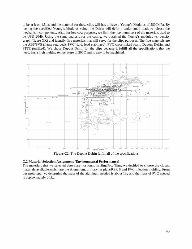
45
to be at least 1.5lbs and the material for these clips will has to have a Young’s Modulus of 2800MPa. By having the specified Young’s Modulus value, the Delrin will deform under small loads to release the mechanism components. Also, for low cost purposes, we limit the maximum cost of the materials used to be USD 20/lb. Using the same analysis for the casing, we obtained the Young’s modulus vs. density graph (figure XX) and identify five materials that will serve for the clips purposes. The five materials are the ABS/PVS (flame retarded), PVC(rigid, lead stabilized), PVC cross-linked foam, Dupont Delrin, and PTFE (unfilled). We chose Dupont Delrin for the clips because it fulfill all the specifications that we need, has a high melting temperature of 200C and is easy to be machined.
Figure C2: The Dupont Delrin fulfill all of the specifications
C.2 Material Selection Assignment (Environmental Performance) The materials that we selected above are not found in SimaPro. Thus, we decided to choose the closest materials available which are the Aluminum, primary, at plant/RER S and PVC injection molding. From our prototype, we determine the mass of the aluminum needed is about 1kg and the mass of PVC needed is approximately 0.1kg.
Density (lb/in^3)0.02 0.025 0.03 0.035 0.04 0.045 0.05 0.055 0.06 0.065 0.07 0.075 0.08 0.085 0.09 0.095 0.1 0.105
Youn
g's
mod
ulus
(10
^6
psi)
1e-5
1e-4
0.001
0.01
0.1
1
10
100

46
Figure C3: Total Mass of Raw materials, air emissions, water emissions, and solid waste for the two
materials indicated We calculate the total mass in grams of air emissions, use of raw materials, and (solid) waste from the SimaPro software for producing one unit of our device. From the figure, producing 1 kg of aluminum will emit more air, waste and solid waste compared to 0.1kg of PVC. However, aluminum required less raw materials for production compared to PVC.
Figure C4: Environmental effects of 1kg of aluminum vs 0.1kg of PVC
0
2000
4000
6000
8000
10000
12000
RAW AIR WATER WASTE
Mas
s (g)
1 kg Aluminum, primary, at plant/RER S 0.1 PVC injection moulding
Method: Eco-indicator 99 (I) V2.07 / Europe EI 99 I/I / CharacterisationComparing 1 kg 'Aluminium, primary, at plant/RER S' with 0.1 kg 'PVC injection moulding E';
Aluminium, primary, at plant/RER S PVC injection moulding E
Carcinogens Resp. organics Resp. inorganics
Climate change Radiation Ozone layer Ecotoxicity Acidification/ Eutrophicatio
Land use Minerals
%
12011511010510095908580757065605550454035302520151050

47
From the figure above, we conclude that producing aluminum is more hazardous and have a bigger impact on the environment. It will release or cause environmental problems that is about a factor of ten larger when compared to 0.1 kg of PVC.
Figure C5: Damage meta-categories caused by Aluminum and PVC
From the figure above, the most important damage meta-categories is from the resources. Human health might be affected in production but the amount is relatively negligible.
Figure C6: Single Score Comparisons in “point”
From the figure above, we concluded that the aluminum production has a higher EcoIndicator 99 “point value” on human health, ecosystem quality and resources. It will definitely have a bigger impact when the life cycle of the whole product is considered. C.3 Manufacturing Process Selection Assignment
Method: Eco-indicator 99 (I) V2.07 / Europe EI 99 I/I / NormalisationComparing 1 kg 'Aluminium, primary, at plant/RER S' with 0.1 kg 'PVC injection moulding E';
Aluminium, primary, at plant/RER S PVC injection moulding E
Human Health Ecosystem Quality Resources
0.02
0.0190.018
0.017
0.0160.015
0.0140.013
0.012
0.0110.01
0.0090.008
0.0070.006
0.005
0.0040.003
0.0020.001
0
Method: Eco-indicator 99 (I) V2.07 / Europe EI 99 I/I / Single scoreComparing 1 kg 'Aluminium, primary, at plant/RER S' with 0.1 kg 'PVC injection moulding E';
Human Health Ecosystem Quality Resources
Aluminium, primary, at plant/RER S PVC injection moulding E
Pt
4.64.44.2
43.83.63.43.2
32.82.62.42.2
21.81.61.41.2
10.80.60.40.2
0

48
In a real world, we approximate the production volume to be on the order of thousands. Our device will be used by faculty members from universities, medical agencies, and medical technicians from the United States and around the world. The aluminum 6013 that we selected using the CES software will be used in the casing and the two housings; the delrin will be used in the clips that release the spring mechanism. In order to mass produce our device, we will produce the aluminum by using the casting method. We think that this process is the best process in terms of time, effort and cost. By casting the aluminum we will come up with the finest finished surface and close tolerance for our device. For the delrin, we will use injection molding for mass production. The injection molding process is the best solution in producing those clips because this process is good in producing small plastic features. Since the clips would not tolerate any flaws in manufacturing, the injection molding process will create those clips efficiently and precisely. APPENDIX D – Engineering Drawings (All Dimensions in Inches) Bottom Plate:
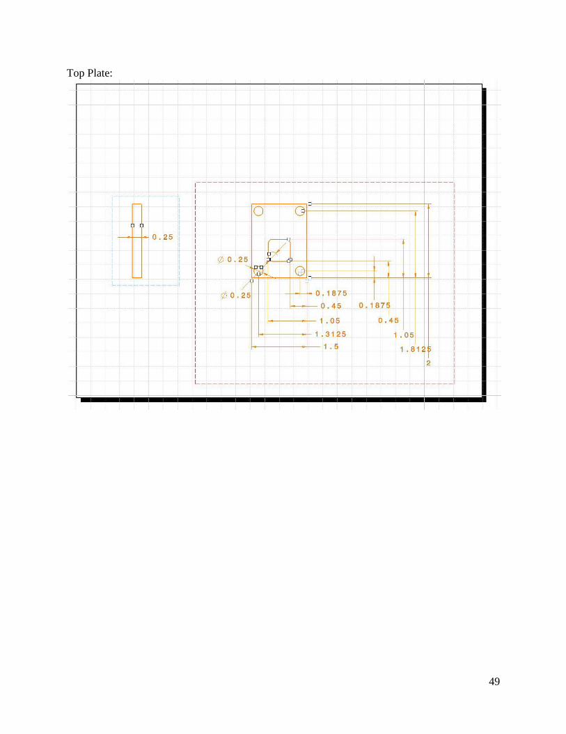
49
Top Plate:

50
Button:

51
Outer Needle Sled:

52
Sled Clips:

53
Retraction Clips:

54
Inner Needle Sled

55
Inner Needle:
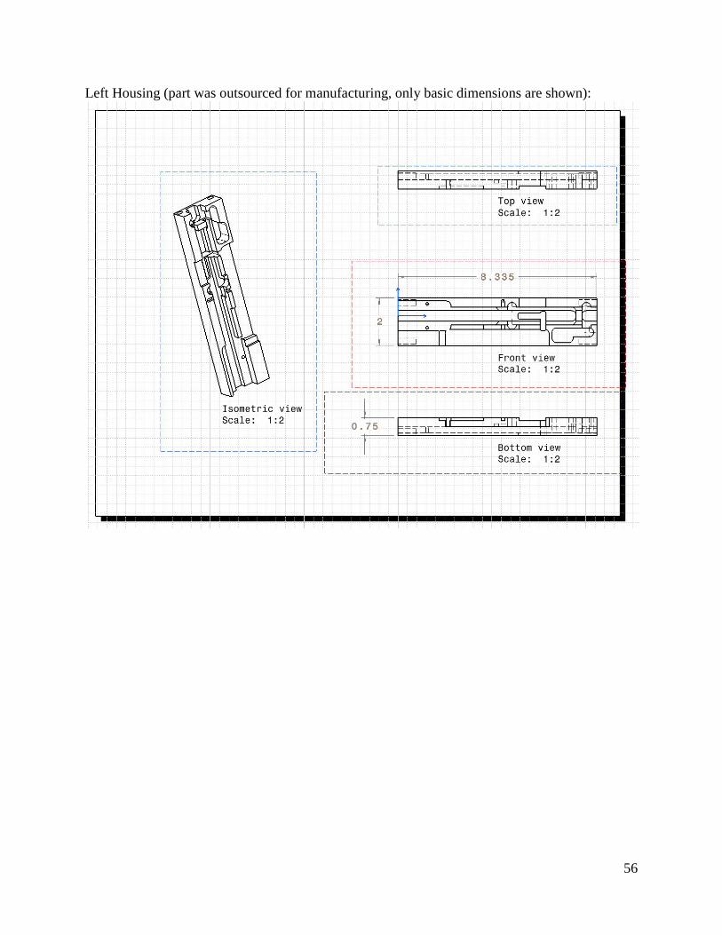
56
Left Housing (part was outsourced for manufacturing, only basic dimensions are shown):

57
Right Housing (part was outsourced for manufacturing, only basic dimensions are shown):

58
Inner Needle Piston:
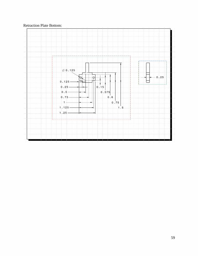
59
Retraction Plate Bottom:

60
Retraction Plate Top:

61
APPENDIX E – QFD

62
APPENDIX F – Concept Drawings

63

64

65
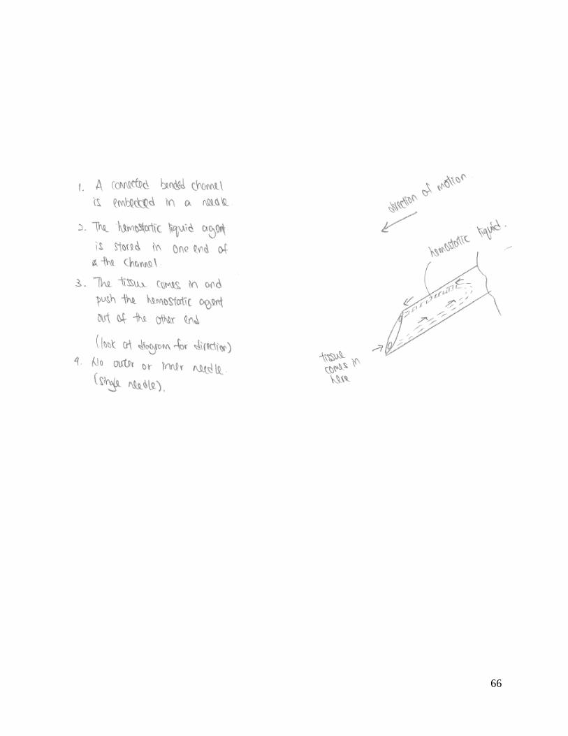
66
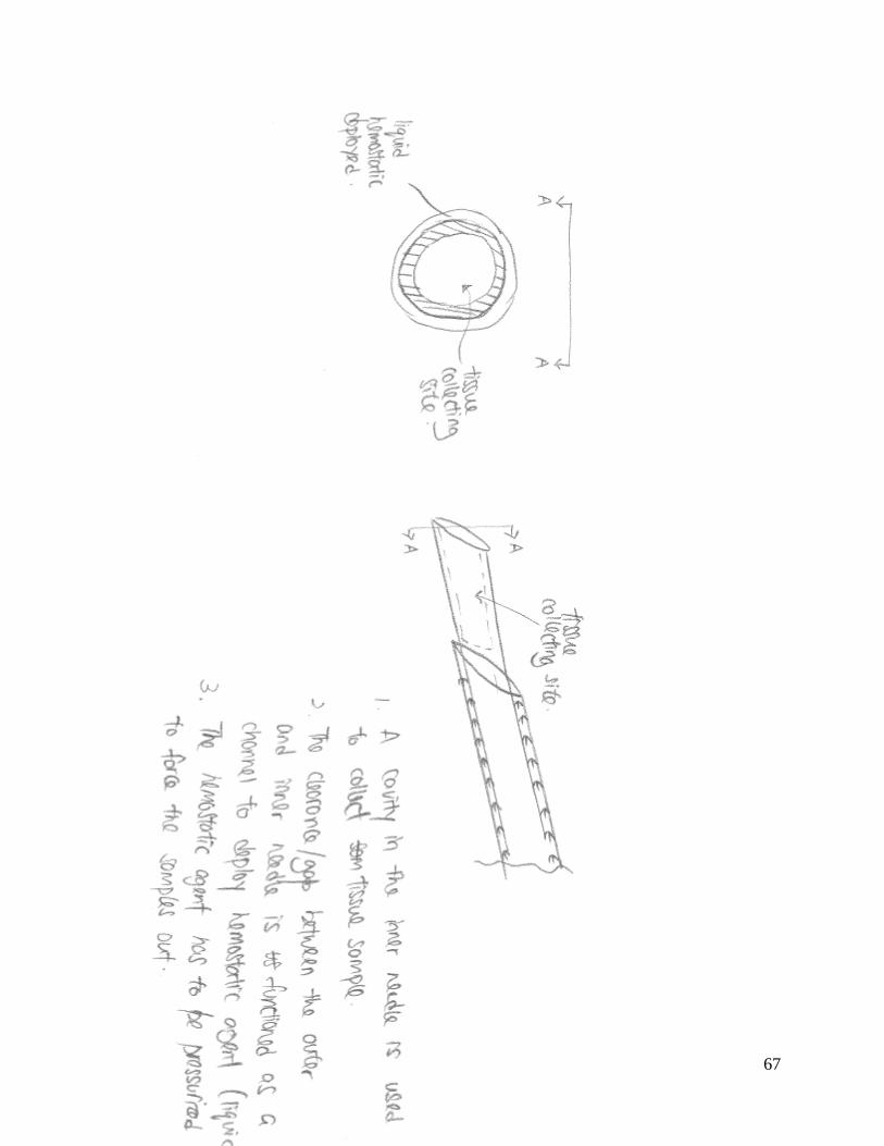
67

68

69

70

71
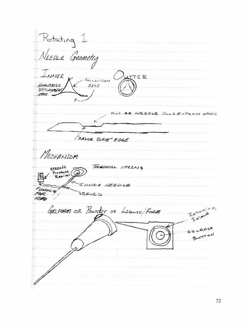
72

73

74

75
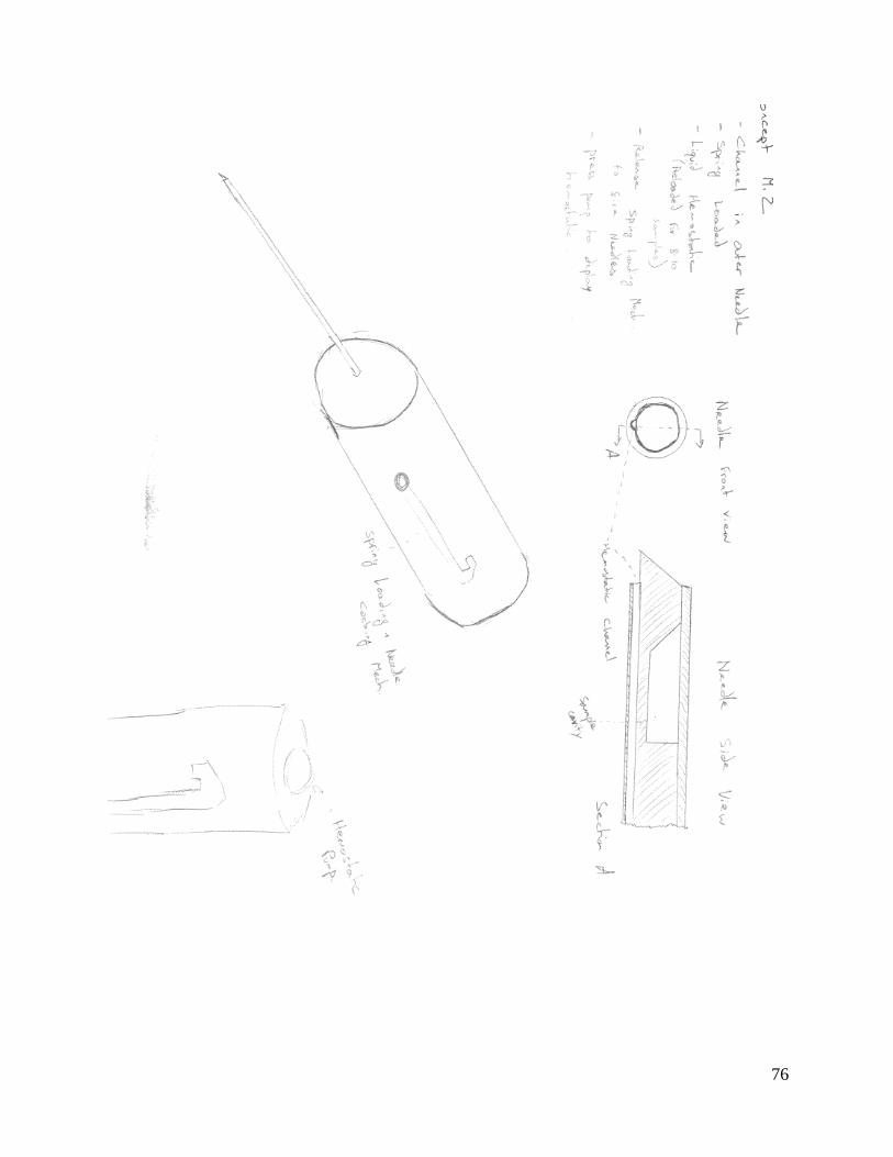
76
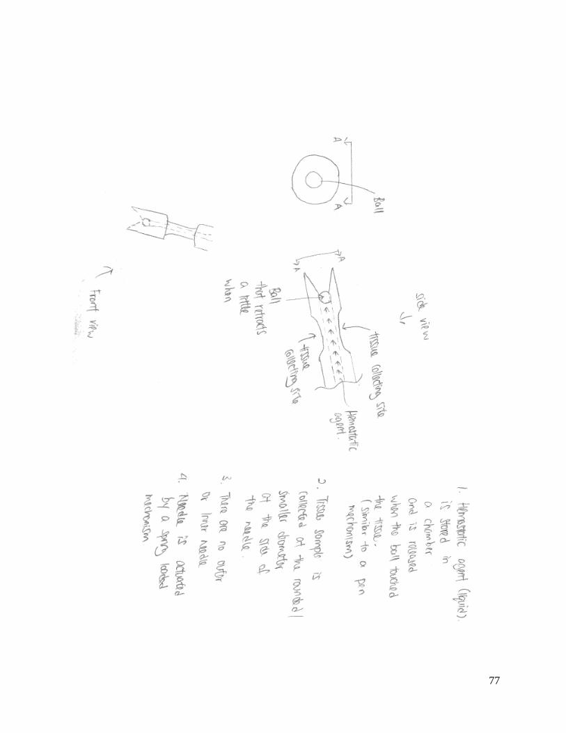
77

78
APPENDIX G – Calculation of Volume of Tissue Sample Collection Site

79
APPENDIX H – Calculation of Tissue Volume Displaced when Performing Biopsy