advanced ligo input optics design requirements reviereitze/adl/presentation.pdfadvanced ligo input...
TRANSCRIPT
LIGO R&DLIGO-G020229-00-D
Advanced LIGO Input Optics Design Requirements Review
Presentation Outline Design Requirements
» Introduction, Production Functions (Dave R., 5 minutes)» Design Requirements (Guido*, 55 minutes)
Conceptual Design» Introduction, Layout (David T., 10 minutes)» RF Modulation (Guido, 10 minutes)» Active Jitter Suppression (Guido, 10 minutes)» Mode Cleaner (David T., 10 minutes)» Faraday Isolation (Dave R., 10 minutes)» Mode Matching (Dave R., 10 minutes)

LIGO R&DLIGO-G020229-00-D
Input Optics Product Functions
RF modulation Input mode cleaning Additional active jitter suppression before
interferometer Laser power control to the interferometer Mode matching (interferometer and mode cleaner) Optical isolation and distribution of sensing beams for
other subsystems internal diagnostics

LIGO R&DLIGO-G020229-00-D
IO Schematic
R FM o d u la ti o n
M CM o d e M a tc h i n gTe le sc o p e
M o d e C le a n e r
M o d e M a tc h i n g Te le sc o p e
Fa ra d a y Iso l a to r
PSL
C O C
ISC
Ste e r in gM irro rs
IFO C o n t ro lto I SC
PSLIn te n si ty Sta b i liza t io nM C A SC
A c tu a ti o n
M C Le n g thA c tu a ti o n
M C Le n g th a n d A lig n m e n t Se n si n g Pd s
A c ti ve Ji tte rSu p p re ssi o n
Po w e rC o n tro l

LIGO R&DLIGO-G020229-00-D
Not Included in IO
Output (AS port) mode cleaner (AOS) Modulation drive (ISC) Suspension design for IO mirrors (SUS)
» Suspension fabrication for large MMT
MC length and alignment sensing and control (ISC) » should be active participation in design by IO group member
Electronics (CDS)» MC » active jitter suppression

ADVANCED LIGO
Primary Requirements from Adv. LIGO Systems Design:
Frequency Noise at IFO, MC, and PSL
Intensity Noise at IFO
Additional Primary Requirements calculated for
P = 125W
Sapphire mirrors
40ppm 50% losses on reflection
1% difference in Arm Cavity Intensities.
DC- and RF-Sensing
Include always safety factor of 10!
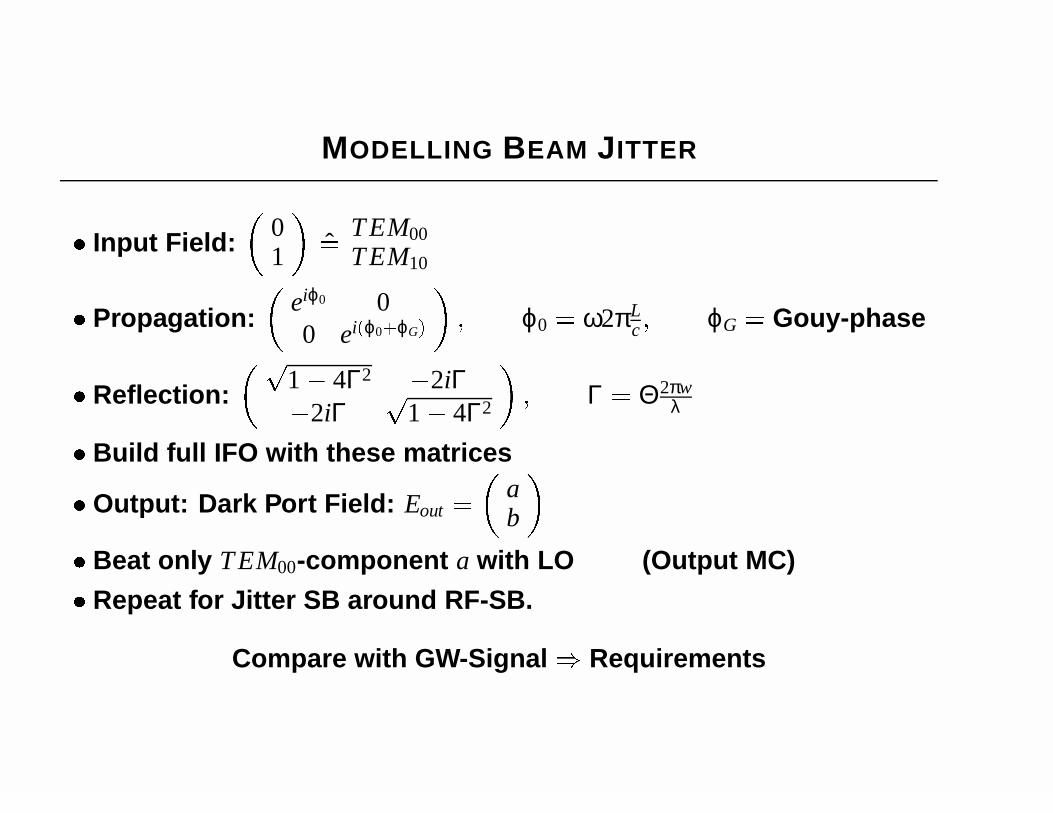
MODELLING BEAM JITTER
Input Field:
01
ˆ=
T EM00T EM10
Propagation:
eiϕ0 00 ei(ϕ0+ϕG)
; ϕ0 = ω2πLc ; ϕG = Gouy-phase
Reflection:
p
1 4Γ2 2iΓ
2iΓ
p
1 4Γ2
; Γ = Θ2πw
λ
Build full IFO with these matrices
Output: Dark Port Field: Eout =
ab
Beat only T EM00-component a with LO (Output MC)
Repeat for Jitter SB around RF-SB.
Compare with GW-Signal ) Requirements

BEAM JITTER
Beam Jitter requirement depend on Mirror Tilt:
∆ΘITM = ΘITM1 ΘITM2
DC-Sensing:
amax10 ( f ) =
s
2:5 105
f 2
2
+ (5 1010)[2 108rad]
∆ΘITM
1
p
Hz
RF-Sensing:
amax10 ( f ) =
s
4:5 105
f 2
2
+ (5:5 1010)[2 108rad]
∆ΘITM
1
p
Hz
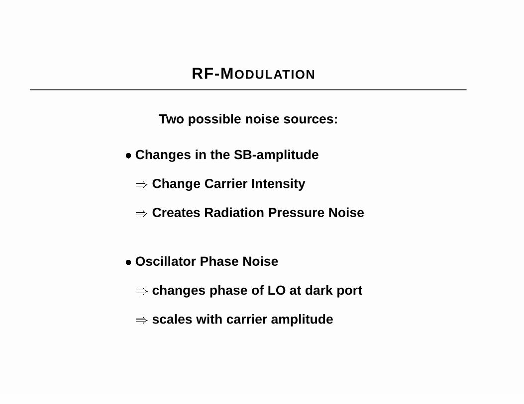
RF-MODULATION
Two possible noise sources:
Changes in the SB-amplitude
) Change Carrier Intensity
) Creates Radiation Pressure Noise
Oscillator Phase Noise
) changes phase of LO at dark port
) scales with carrier amplitude

RF-MODULATION
Changes in SB-Amplitude
DC-Sensing:
δm( f ) <
109
m0
p
Hz
f
[10Hz]RF-locking:
δm( f ) <
109
m0
p
Hz
f
[10Hz]f < 100Hz
δm( f ) <
108
m0
p
Hzf > 100Hz

OSCILLATOR PHASE NOISE
E = E0eiωctexp
im cos
Ωt +
δν2πf
sin(2πf t)
Dark Port:
Input Field:
Detuned Interferometer:
both RF-sidebands differentamplitude and phase
all noise sidebands differentamplitude and phase
Two contributions:
OPN-Sidebands beat with Carrieron PD.
Oscillator Phase Noise in LO atmixer.
No Noise Cancellation anymore !

RF-MODULATION
Requirements for 180 MHz:
ISSB(10Hz) < 92 dBc/Hz
ISSB(100Hz) < 140 dBc/Hz
ISSB(1 kHz) < 163 dBc/HzCritical Parameters:
Detuning in arm cavities and MI
Φ
< 107rad φ
< 104rad
Differential Losses in arm cavities
∆L < 15 ppmReason: Scales with Amplitude of Carrier at DP.
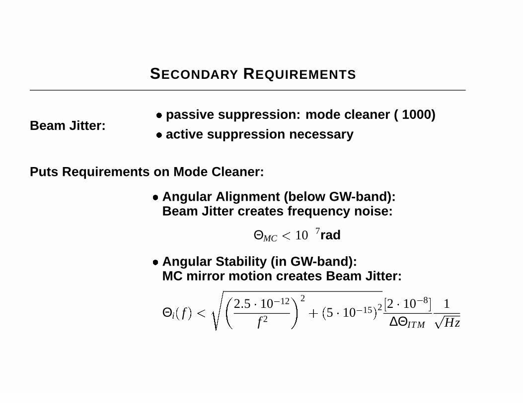
SECONDARY REQUIREMENTS
Beam Jitter:
passive suppression: mode cleaner ( 1000)
active suppression necessary
Puts Requirements on Mode Cleaner:
Angular Alignment (below GW-band):Beam Jitter creates frequency noise:
ΘMC < 107rad
Angular Stability (in GW-band):MC mirror motion creates Beam Jitter:
Θi( f ) <s
2:5 1012
f 2
2
+ (5 1015)2 [2 108]
∆ΘITM
1
p
Hz

ADDITIONAL REQUIREMENTS
Frequency Noise Requirement behind MClimited by radiation pressure noise
) 3 102 Hzp
HzHzf f < 1 kHz
) 3 105 Hzp
Hzf > 1 kHz
Oscillator Phase Noise and SB-Amplitudecouple if FSR 6= RF-frequency
) Difference between FSR & RF-frequency < 14Hz
) Otherwise Requirements start to change
MODE MATCHING
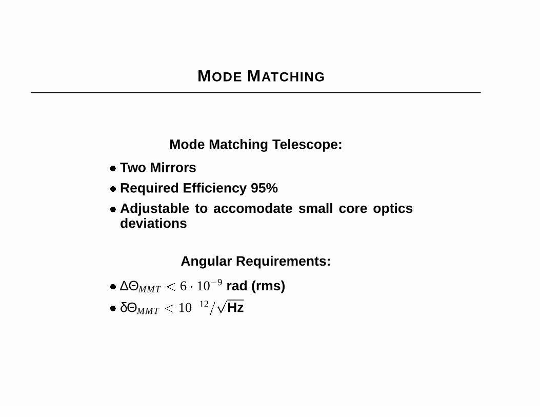
Mode Matching Telescope:
Two Mirrors
Required Efficiency 95%
Adjustable to accomodate small core opticsdeviations
Angular Requirements:
∆ΘMMT < 6 109 rad (rms)
δΘMMT < 1012=p
Hz
LASER INTERFEROMETER GRAVITATIONAL WAVE OBSERVATORY
LIGO-G020229-00-D
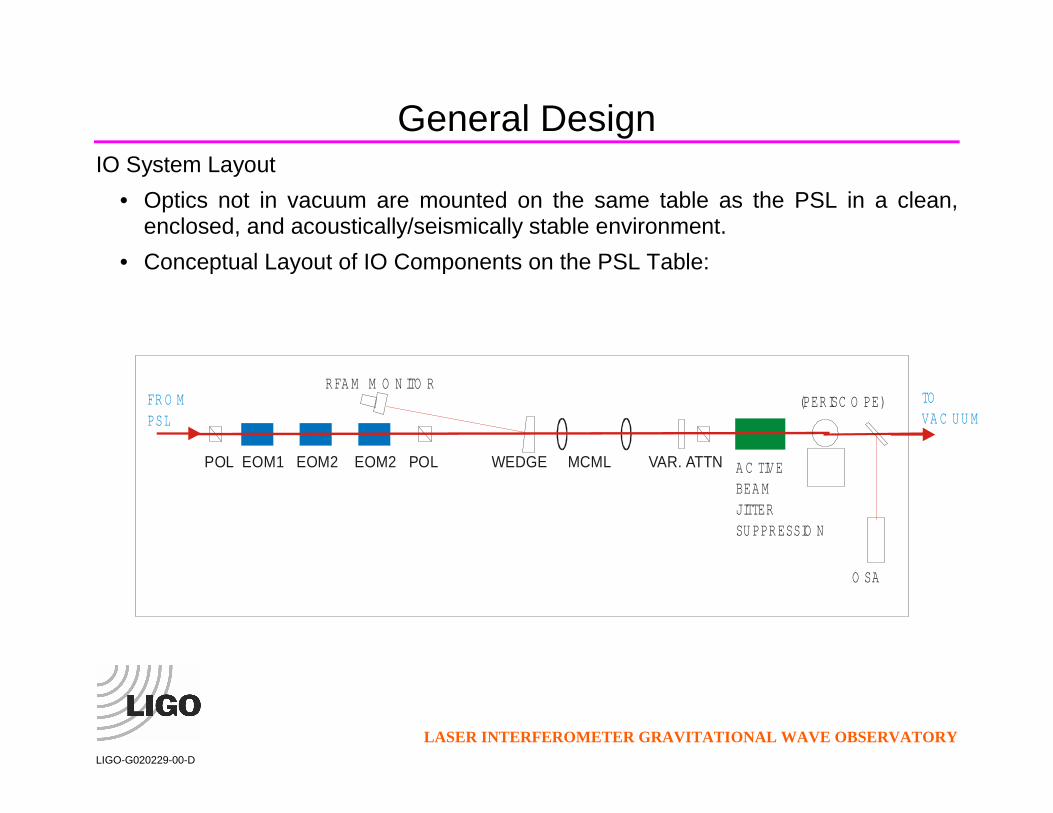
General Design IO System Layout
• Optics not in vacuum are mounted on the same table as the PSL in a clean, enclosed, and acoustically/seismically stable environment.
• Conceptual Layout of IO Components on the PSL Table:
POL EOM1 EOM2 EOM2 POL WEDGE MCML VAR. ATTN
(PER ISC O PE)
O SA
A C TIV EBEA M JITTERSU PPR ESSIO N
R FA M M O N ITO RFR O MPSL
TO VA C U U M

LASER INTERFEROMETER GRAVITATIONAL WAVE OBSERVATORY
LIGO-G020229-00-D
Possible Methods for Minimizing Frequency Noise from Acoustic Coupling to Mirror Mounts and Periscopes
• LIGO 1 suffered from coupling of acoustic noise in the PSL/IOO table
environment to mirror mounts. 1) enclose PSL components in separate vacuum (with suitable vibration isolation). 2) provide low-acoustic (anechoic) enclosure around PSL with all noise producing devices (fans, etc) outside this enclosure.
• PSL/IOO table of L1 was not stiff enough to constrain the (heavy) periscope frame first employed; eventually a lighter design was used. 1) move periscope into vacuum system (requires a HAM viewport at table level). 2) raise table to eliminate periscope.
• Both treatments are outside the scope of the IOO subsystem alone.

LASER INTERFEROMETER GRAVITATIONAL WAVE OBSERVATORY
LIGO-G020229-00-D
In-vacuum optics • With the exception of the Faraday isolator, all main IFO beam optics including
and following the mode cleaner will be suspended. • Diagnostic beam optics for IFO and MC control will be located on fixed mounts. • Output ports in the HAMs used as optical feedthroughs for sensing beams.

LASER INTERFEROMETER GRAVITATIONAL WAVE OBSERVATORY
LIGO-G020229-00-D
LASER INTERFEROMETER GRAVITATIONAL WAVE OBSERVATORY
LIGO-G020229-00-D

LASER INTERFEROMETER GRAVITATIONAL WAVE OBSERVATORY
LIGO-G020229-00-D
LASER INTERFEROMETER GRAVITATIONAL WAVE OBSERVATORY
LIGO-G020229-00-D
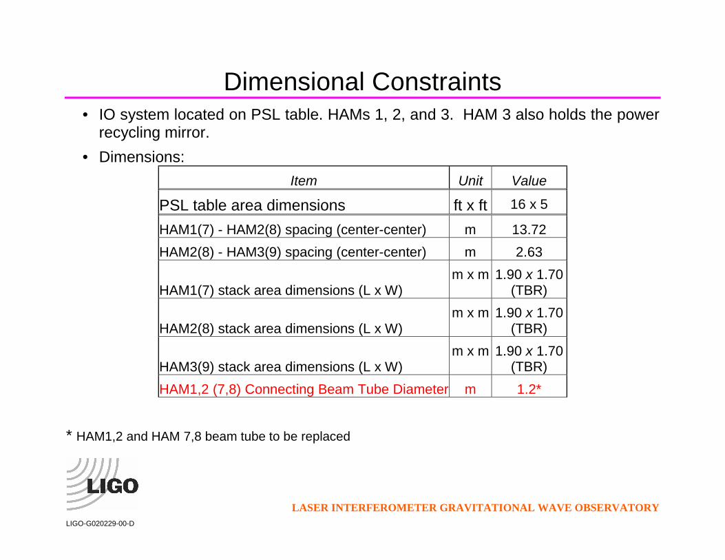
Dimensional Constraints • IO system located on PSL table. HAMs 1, 2, and 3. HAM 3 also holds the power
recycling mirror. • Dimensions:
Item Unit Value
PSL table area dimensions ft x ft 16 x 5
HAM1(7) - HAM2(8) spacing (center-center) m 13.72 HAM2(8) - HAM3(9) spacing (center-center) m 2.63
HAM1(7) stack area dimensions (L x W) m x m 1.90 x 1.70
(TBR)
HAM2(8) stack area dimensions (L x W) m x m 1.90 x 1.70
(TBR)
HAM3(9) stack area dimensions (L x W) m x m 1.90 x 1.70
(TBR) HAM1,2 (7,8) Connecting Beam Tube Diameter m 1.2*
* HAM1,2 and HAM 7,8 beam tube to be replaced

LASER INTERFEROMETER GRAVITATIONAL WAVE OBSERVATORY
LIGO-G020229-00-D
Dimensional Constraints, cont.
∆z (HAM1-HAM2, local coordinates, LHO) mm 8.49†
∆z (HAM2-HAM3, local coordinates, LHO) mm 1.59†
∆z (HAM7-HAM8, local coordinates, LHO) mm -8.49†
∆z (HAM8-HAM9, local coordinates, LHO) mm -1.59†
∆z (HAM1-HAM2, local coordinates, LLO) mm 4.28†
∆z (HAM2-HAM3, local coordinates, LLO) mm 0.80†
† The LHO x-axis slopes downward by 0.619 mrad; the y-axis slopes upward by 0.012 mrad. WHAM1 (7) is 8.5 mm higher (lower) than WHAM2 (8). At LLO the x-axis slopes downward by 0.312 mrad and the y-axis slopes downward by 0.612 mrad. LHAM1 is 4.3 mm higher than LHAM2.
• Suspensions must either be raised on platform or have adjustment capability so that the plane of the MC beam is level
• Capability for optical levers on all suspended mirrors required.

LASER INTERFEROMETER GRAVITATIONAL WAVE OBSERVATORY
LIGO-G020229-00-D
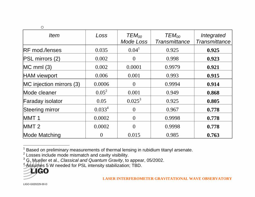
Overall IO Efficiency • Requirement: IO must deliver 76% of the PSL TEM00 light to the IFO • Includes all losses from reflection, transmission, and absorption in the IO optical
components, as well as light lost into uncompensated higher order modes through thermal lensing.
• Transmission of the components of the IO components: o Suspended components assumed to have coatings similar those achieved
in the LIGO I (~50 ppm loss) o Other optics assumed to have antireflection coatings that match the
standard commercial narrowband multilayer coatings (0.1%). o Out-of-vacuum optics assumed to have 200 ppm scatter. o Loss of TEM00 mode in the RF modulators and Faraday isolator are based
on conservative estimates of passive thermal lensing compensation using –dn/dT values for FK51 Schott glass.
LASER INTERFEROMETER GRAVITATIONAL WAVE OBSERVATORY
LIGO-G020229-00-D
o Item Loss TEM00
Mode Loss TEM00
Transmittance Integrated
Transmittance RF mod./lenses 0.035 0.041 0.925 0.925 PSL mirrors (2) 0.002 0 0.998 0.923 MC mml (3) 0.002 0.0001 0.9979 0.921 HAM viewport 0.006 0.001 0.993 0.915 MC injection mirrors (3) 0.0006 0 0.9994 0.914 Mode cleaner 0.052 0.001 0.949 0.868 Faraday isolator 0.05 0.0253 0.925 0.805 Steering mirror 0.0334 0 0.967 0.778 MMT 1 0.0002 0 0.9998 0.778 MMT 2 0.0002 0 0.9998 0.778 Mode Matching 0 0.015 0.985 0.763
1 Based on preliminary measurements of thermal lensing in rubidium titanyl arsenate. 2 Losses include mode mismatch and cavity visibility. 3 G. Mueller et al., Classical and Quantum Gravity, to appear, 05/2002. 4 Assumes 5 W needed for PSL intensity stabilization; TBD.

MODULATION
Material: RTP (back up RTA)
Properties RTA RTP LiNbO3Laser Damage Threshold 400 600 280b
[MW/cmˆ2, 10ns 1064nm] coatednx @ 1064nm 1.8 1.9a 2.23ny @ 1064nm 1.8 1.9a 2.23nz @ 1064nm 1.9 1.9a 2.16
αc @ 1064 nm [1/cm] 50ppm 50ppm 0.5%r33n3
z 273 272 306
Half Wave Voltage within 10% of LiNbO3
Thermal Lensing very smallTemperature Changes change Modulation Index:
δT 33µKp
Hz
1m2
f
[10Hz]
MODULATOR
Modulator Design:
Material: RTP
Temperatur stabilized
Alignment very critical(active stabilized if necessary)
Thermal Lensing very small(if needs compensation ) FK51)
Oscillator Phase Noise:At the edge of state of the art Oscillators
Very Critical !!

POINTING
Requirements:
MC reduces pointing by factor 1000
need active suppression (at least by 10..100)
Actuators:
PZT-mounted mirrors
RTP-prisms (will be studied)
Detection (under study):
wave front sensing at MC or IFO
Quad-Detector on HAM
fixed spacer cavity on HAM

POINTING-ACTUATOR
Assume Laser Pointing of
a10( f ) 2 106=p
Hz f = 10 Hz::10 kHz
Requirements: Actuator Range: δβ 7 1010 rad
Frequency Range: 10Hz..10kHz
Two Possible actuators: PZT-mounted mirrors:
– a PZT on each side of the mirror– required length change 10pm
RTP-prism: δn 108 ) δV = 1V
βα

POINTING-DETECTION
Reference for Pointing:
below GW-band: HAM-table is reference
in GW-band: Mode Cleaner is reference
Detection of Pointing:
below GW-band: Quad-Detector or fixed spacer cavity in front of MC
in GW-band: Wave front sensing
– below GW-band: aligns mode cleaner– above GW-band: suppresses pointing

POINTING-DETECTION
Concept:
RTP
MCWFS
QuadsorCavity (+WFS)
to FI
WFS @ MC
– DC-10 Hz:align MC
– > 10 Hz:align beamusing RTP
WFS @ FixedSpacer Cavityor Quad. Det.
– DC-10 Hz:align beamusing PZT

LASER INTERFEROMETER GRAVITATIONAL WAVE OBSERVATORY
LIGO-G020229-00-D
Mode Cleaner The suspended mode cleaner of the IO subsystem serves the following functions in stabilizing the laser light.
• In-band active frequency stabilization. • Rejection of laser output not in the TEM00 mode. (Beam Jitter suppression.) • Passive intensity and frequency stabilization above the cavity pole frequency.
LASER INTERFEROMETER GRAVITATIONAL WAVE OBSERVATORY
LIGO-G020229-00-D
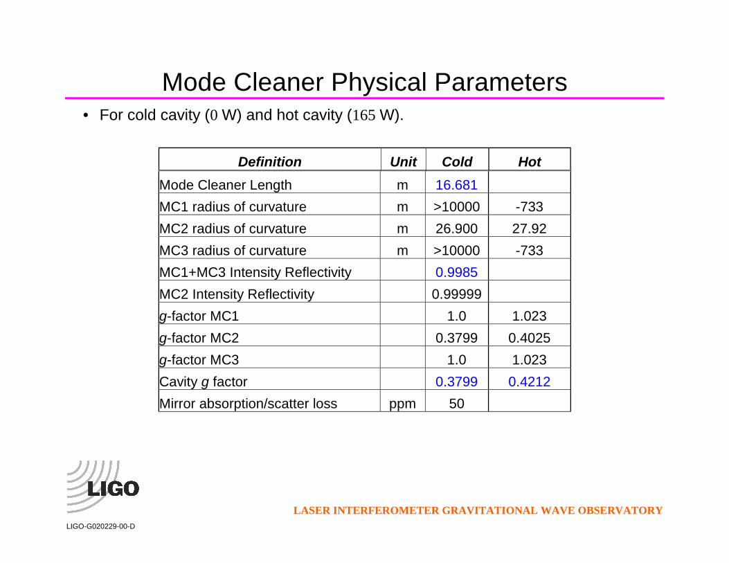
Mode Cleaner Physical Parameters • For cold cavity (0 W) and hot cavity (165 W).
Definition Unit Cold Hot Mode Cleaner Length m 16.681 MC1 radius of curvature m >10000 -733 MC2 radius of curvature m 26.900 27.92 MC3 radius of curvature m >10000 -733 MC1+MC3 Intensity Reflectivity 0.9985 MC2 Intensity Reflectivity 0.99999 g-factor MC1 1.0 1.023 g-factor MC2 0.3799 0.4025 g-factor MC3 1.0 1.023 Cavity g factor 0.3799 0.4212 Mirror absorption/scatter loss ppm 50

LASER INTERFEROMETER GRAVITATIONAL WAVE OBSERVATORY
LIGO-G020229-00-D
MC free spectral range Hz 8986045 MC finesse 2074 MC waist mm 2.102 2.114 Cavity Pole Frequency Hz 4544 Rayleigh range m 13.06 13.99 Input Power W 165 Stored MC Power kW 100 MC mirror mass kg 2.92 MC mirror diameter cm 15 MC mirror thickness cm 7.5 Static Radiation pressure N/m^2 0.00035

LASER INTERFEROMETER GRAVITATIONAL WAVE OBSERVATORY
LIGO-G020229-00-D
Physical Layout • Triangular cavity • Triple-pendulum suspensions • Fused silica mirrors • Changes from the LIGO I mode cleaner:
o slightly increased length (Mirrors occupy HAMs 1 and 3) o larger mass mirrors (Mirrors have 12-fold increase in mass)

LASER INTERFEROMETER GRAVITATIONAL WAVE OBSERVATORY
LIGO-G020229-00-D
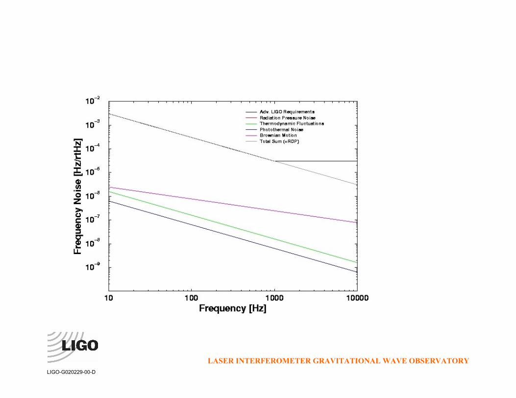
Frequency Noise • Frequency stability is limited by technical radiation pressure noise over the entire
frequency range. • This stability and the allowed frequency noise of the field going into the main
interferometer set the requirements on the frequency stabilization loop gains. • Expected frequency noise (+ individual contributions to the MC frequency noise)
LASER INTERFEROMETER GRAVITATIONAL WAVE OBSERVATORY
LIGO-G020229-00-D

LASER INTERFEROMETER GRAVITATIONAL WAVE OBSERVATORY
LIGO-G020229-00-D
Beam Jitter Stabilization • The mode cleaner acts as a spatial filter, providing passive stabilization of time-
dependent higher-order spatial modes. • Attenuation of higher-order modes (amplitude) for cold/hot cavity, assuming PSL
jitter spec of 2 x 10⁻⁶ /Hz1/2
Index (n+m)
Amplitude transmission
Suppression Factor
Output Jitter
Cold Hot Cold Hot Cold Hot 1 0.00096 0.00100 1040 1004 1.92E-09 1.99E-09 2 0.00078 0.00077 1281 1304 1.56E-09 1.53E-09 3 0.00185 0.00146 540 687 3.70E-09 2.91E-09 4 0.00162 0.00243 616 412 3.25E-09 4.86E-09 5 0.00077 0.00082 1299 1222 1.54E-09 1.64E-09 6 0.00101 0.00085 986 1174 2.03E-09 1.70E-09 7 0.01190 0.00332 84 302 2.38E-08 6.63E-09 8 0.00092 0.00128 1089 782 1.84E-09 2.56E-09 9 0.00079 0.00076 1259 1317 1.59E-09 1.52E-09 10 0.00216 0.00108 462 927 4.33E-09 2.16E-09

LASER INTERFEROMETER GRAVITATIONAL WAVE OBSERVATORY
LIGO-G020229-00-D
11 0.00145 0.00875 689 114 2.90E-09 1.75E-08 12 0.00076 0.00093 1311 1075 1.53E-09 1.86E-09 13 0.00108 0.00078 928 1281 2.16E-09 1.56E-09 14 0.00596 0.00170 168 587 1.19E-08 3.41E-09 15 0.00088 0.00193 1135 519 1.76E-09 3.86E-09

LASER INTERFEROMETER GRAVITATIONAL WAVE OBSERVATORY
LIGO-G020229-00-D
Thermal Distortion • Absorption ! changes in effective radii of curvatures. Change of sagitta δs:
aPsπκαδ
4=
• α, thermal expansion coefficient; κ heat conductivity; and Pa absorbed power. • Based on coating absorption coefficient of 1 ppm, fused silica mirror:
nms 3≈δ • Radii of flats -> -733 m; R of curved mirror changes from 26.9 m to 27.9 m • Substrate acts as thermal lens for input and output beams:
πκδ
4aP
Tns
∂∂=
• Using (fused silica) 1 ppm/cm, effective sagitta change of transmitted beam is: nms 1≈δ
• The induced focal length of about 1 km neither changes the beam quality nor affects the mode matching.

LASER INTERFEROMETER GRAVITATIONAL WAVE OBSERVATORY
LIGO-G020229-00-D
Alignment Procedure • Use fixtures for installation of the suspended mirrors • Fixed targets for initial beam alignment using the PSL laser (suspensions need to
accommodate these). • In-air and in-vacuum resonance measurements for fine beam alignment • Measure free spectral range for final length adjustment. • Will be tested at LASTI.
Mode Cleaner Mode Matching • Baseline system resembles closely LIGO I three-lens configuration.

LIGO R&DLIGO-G020229-00-D
Faraday Isolator I
Conventional FIs limited to ~20-30 dB isolation at high powers» depolarization from thermo-elastic deformation
Compensated crystal design approaches 45 dB isolation
» limited by polarizers
LIGO R&DLIGO-G020229-00-D
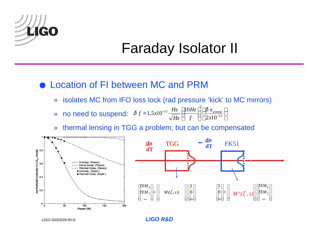
Faraday Isolator II
Location of FI between MC and PRM» isolates MC from IFO loss lock (rad pressure ‘kick’ to MC mirrors)
» no need to suspend:
» thermal lensing in TGG a problem; but can be compensated
=
...),(
...~
~
01
2
0
zMTEMTEM
ζ
dndT
=
......~
~
2
0
01
TEMTEM
M-1(ζ , z)
dndTTGG FK51
= −
−13
212
102101051
xx
fHz
HzHzxf seismicδδ .

LIGO R&DLIGO-G020229-00-D
Faraday Isolator III
Experiment: » highly absorbing TGG» 97.5% TEM00 mode at power levels of 150 W
FI Design Process» screen for low α TGG» build, test isolation unit» determine optimal FK51 length for best compensation» build, test integrated compensated FI

LIGO R&DLIGO-G020229-00-D
Mode Matching Telescope
Two mirror design» LIGO I uses three mirrors
– can compensate for waist size, position mismatch– requires (multiple) vacuum excursions
» MMT1 is small 3” optic (SOS)– could be MC sized optic if stack resonances are a problem
» MMT2 is PRM-sized optic (both size and suspension)
Third element is adaptive » no vacuum excursions
Detailed design needs final core optics configuration Pointing and alignment stability
» stacks,suspensions very quiet1; meets requirements1LIGO-T000053-01-D “Cavity Optics Suspension Subsystem Design Requirements Document, P. Willems, et al.
LIGO R&DLIGO-G020229-00-D
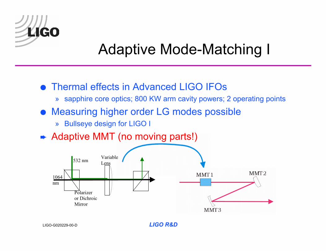
Adaptive Mode-Matching I
Thermal effects in Advanced LIGO IFOs» sapphire core optics; 800 KW arm cavity powers; 2 operating points
Measuring higher order LG modes possible» Bullseye design for LIGO I
Adaptive MMT (no moving parts!)
1064 nm
532 nm
Polarizer or Dichroic Mirror
Variable Lens

LIGO R&DLIGO-G020229-00-D
Adaptive Mode-Matching II• variable lens material: OG590 Schott glass
• transmittance @ 1064 nm: >0.9999 Pincident, 532 nm: <0.00001 Pincident
• scatter: 0.03 – 0.10 mm2 of cross sectional area for 100 mm3 volume• mounted directly to table
• heating laser: DPSS Nd:VO4, 532 nm (could use different λ)• 10 W • amplitude and pointing stability TBD• waist: 6 mm at glass
·lensing ·1064 waist: 2-3 mm· ∆OPD @ 532 nm: ~10-6 m/W; ∆OPD @ 1064 nm: ~ 0.2-0.3 x 10⁻⁶
m/W· effective focal length range for 1064 nm: + 9.4 m to infinity
LIGO R&DLIGO-G020229-00-D
Adaptive Mode-Matching III
Preliminary Design Plan» detailed MMT design using 2 mirrors + variable lens» thermal modal modeling
– optimal ratio of waist sizes» prototype table top demonstration
– characterization of effective mode matching range– characterization of modal distortions

Cost estimate (based on T. Frey work of summer 2001) IO Subsystem Management 225,150 IO Design 1,360,977 IO Fabrication 3,170,122 Modulation/jitter suppression 3 x 195,426 Mirror blanks 3 x 182,615 Mirror polishing 3 x 212,200 Mirror coatings 3 x 116,290 Metrology 3 x 14,700 Isolator 3 x 296,640 Tooling and installation 116,500 Total 4,756,250 This is for 4 subsystems (i.e., includes IO components for LASTI)