advanced learning packages - unesdoc …unesdoc.unesco.org/images/0014/001494/149493e.pdf ·...
TRANSCRIPT
SC/BES/MCS/2006/4 December 2006
Original: English
ADVANCED LEARNING PACKAGES:
MICROELECTRICITY EXPERIENCES
STUDENT WORKSHEETS
Prepared under UNESCO Contract No. .................................. Printed under UNESCO Contract No. .....................................
Prepared by: Ms B. Bell Worksheets created by: Ms M. Lycoudi and Mrs J. Ovens
Worksheets edited by: Prof. J. D. Bradley
IN COLLABORATION WITH:
The RADMASTE Centre University of the WitwatersrandJohannesburg, South Africa
Somerset Educational Somerset East South Africa

CONTENTS
FOREWORD 6 INTRODUCTION 7
PART I: STUDENT WORKSHEETS 8
CHAPTER 1 A. THE ELECTRIC CURRENT 9 ACTIVITY 1 GET TO KNOW YOUR MICROELECTRICITY KIT 10 ACTIVITY 2 LIGHTEN UP, PREDICT AND EXPLORE 13 ACTIVITY 3 CAR HEADLIGHTS 15 ACTIVITY 4 MAKING AN ELECTRIC CURRENT DETECTOR 17 ACTIVITY 5 THE CURRENT IN A SERIES CIRCUIT 19 ACTIVITY 6 LIGHT BULBS IN SERIES 21 ACTIVITY 7 LIGHT BULBS IN PARALLEL 23 ACTIVITY 8 CELLS AND MORE CELLS 25 ACTIVITY 9 FRUIT COCKTAIL 27 B. EFFECTS OF THE ELECTRIC CURRENT 29 ACTIVITY 10 SOME GOLDEN CHAINS! – ELECTROPLATING 30 ACTIVITY 11 COMING ATTRACTION 32 ACTIVITY 12 FIELDING 34 ACTIVITY 13 THE STRONGEST OF THEM ALL! 36
CHAPTER 2 CURRENT ELECTRICITY 38 ACTIVITY 1 RATES AND FLOWS 39 ACTIVITY 2 AMMETER – TO BE OR NOT TO BE 41 ACTIVITY 3 GO WITH THE FLOW 43 ACTIVITY 4 ONE, TWO, THREE, …. TROUBLE! 45 ACTIVITY 5 ONE AFTER THE OTHER CAUSING A GREAT BOTHER 47 ACTIVITY 6 FREE ELECTRONS ARE NOT SO FREE! 49 ACTIVITY 7 PARALLEL CELLS 57
2
ACTIVITY 8 FIRST CONTACT WITH THE LOOPS 59
CHAPTER 3
A. THE ELECTRIC CURRENT 61 ACTIVITY 1 THE MODELLING BUSINESS 62 ACTIVITY 2 WHAT GOES UP MUST FALL DOWN 64 ACTIVITY 3 THE CURRENT IN A SERIES CIRCUIT 66 ACTIVITY 4 THE REAL & THE IDEAL WORLD 68 ACTIVITY 5 THE INVESTIGATION 70 B. ELECTROMAGNETISM & ELECTROMAGNETIC INDUCTION 71 ACTIVITY 1 FANCY EFFECTS 72 ACTIVITY 2 THE SHAPE OF IT 74 ACTIVITY 3 SOLENOIDS AND ELECTROMAGNETS 76 ACTIVITY 4 FEDERAL BUREAU OF INVESTIGATIONS, FBI 78 ACTIVITY 5 ELECTRIC MOTOR 1 80 ACTIVITY 6 ELECTRIC MOTOR 2 82 ACTIVITY 7 CAN MAGNETISM PRODUCE ELECTRICITY? 84
CHAPTER 4
A. ELECTRIC CURRENT & ELECTRICAL RESISTANCE 86 ACTIVITY 1 ON, OFF – OFF, ON 87 ACTIVITY 2 LET THERE BE LIGHT! 89 ACTIVITY 3 WHAT IS ELECTRICAL POTENTIAL DIFFERENCE? 93 ACTIVITY 4 THE MAXIMUM POTENTIAL ENERGY OUTPUT OF A BATTERY 95 ACTIVITY 5 POTENTIAL DIFFERENCE ACROSS POINTS IN A SERIES
CIRCUIT 97 ACTIVITY 6 POTENTIAL DIFFERENCE ACROSS POINTS IN A PARALLEL CIRCUIT 98 ACTIVITY 7 OHM'S LAW 100 B. THE MAGNETIC EFFECT OF AN ELECTRIC CURRENT 102 ACTIVITY 1 PARALLELISMS 103

FOREWORD
All over the world, science educators declare that practical experiences are an essential part of learning science. However, in many countries these experiences are not provided in the majority of their primary and secondary schools. There are several reasons for this: cost, safety, waste disposal and teacher preparation. To help overcome these problems, microchemistry kits and workbooks were designed by the RADMASTE Centre. In cooperation with UNESCO and IUPAC, these have been brought to the attention of educators in more than 40 countries. This has led to pilot projects and wider implementation in many of these countries.
Another consequence has been the motivation to extend our work into other areas of science. We have begun with electricity and, with this workbook, now introduce microelectricity.
The microelectricity kits are designed to be easy to use, robust and versatile. They should therefore be useful in all countries, just like the traditional, larger equipment. So students now can do most of the same experiments as students were intended to do before, but more safely and at less cost.
The workbook is a different matter. Each country has its own school curriculum and its own way of delivering that curriculum. Indeed, each teacher is an individual, and in each classroom the story is a little different. This workbook therefore provides a starting point only. The worksheets were originally designed at the RADMASTE Centre, University of the Witwatersrand in South Africa to suit the South African curriculum. Using them, teachers and students in any country should be able to complete successfully a wide range of basic electricity experiments with the microelectricity kits.
We hope that this experience is enjoyable, and that the teachers will improve and modify the experiments in the light of their experience.
In modern laboratories around the world, science is increasingly done on the small scale. This is because it costs less, is safer and is less damaging to the environment. This workbook can help school science to quickly pick up this trend and make personal experiences accessible to all students.
Prof J D Bradley DIRECTOR: RADMASTE Centre
6
A UNESCO Associated Centre
INTRODUCTION
This is a new teaching and learning package prepared by the RADMASTE CENTRE of the University of the Witwatersrand (South Africa) in cooperation with UNESCO. These materials should mostly be used for teacher-training courses, the practical laboratory work of students and self-training of those who are working with provisional types of microscience kits. It should be very simple to adapt these materials to all different curricula: some proposed experiments can be kept, some of them can be revised. These are very easy materials for all types of modifications. These materials were called teaching and learning packages because, in all four chapters, there are a lot of different sections: some for teachers, some for students. In the countries where the project is going, the same publications can be prepared as two different ones after adapting them to the national curricula:
– one as a teaching and learning package - for the teachers; – the other one as a learning package, for the students only.
We are able to prepare and print these packages, mostly by using the extra-budgetary resources received by UNESCO and, especially, from the RADMASTE Centre and the Kenyan Centre for Science and Technology Innovations, both UNESCO Associated Centres.
These packages are not for sale; they are to be freely distributed through our existing and future partners. And the main role of this publication is to help understand better the facilities of the project on microscience experiments.
We hope that you will find it easy to use the materials within your national curricula, and if so, we shall be highly satisfied in the future.
Do take these packages as an example for your own self-financed training and thinking.
A. Pokrovsky Division of Mathematics, Physical and Chemical Sciences
UNESCO
PART I
8
STUDENT WORKSHEETS

CHAPTER 1
A. THE ELECTRIC CURRENT
ACTIVITY 1 - GET TO KNOW YOUR MICRO-ELECTRICITY KIT Nowadays everything is going “micro”, which of course means “small”. This micro fever, ranges from computers and Hi-Tech equipment to laboratory equipment. Micro-things become more and more affordable, they are easy to carry and easy to store. In schools all over the world, micro-equipment invades the classrooms and changes the way of teaching and learning. Work with your micro-electricity kit and you will find out why. What you need micro-electricity kit, an A4 sheet of white paper WHY DO WE USE ELECTRIC CIRCUITS? 1 We use electric circuits to transfer electrical energy to various electrical devices. These devices transform
the electrical energy into other forms of energy, which we find useful! a Make a list of five devices which you can find at home, or you see in the shops, which work with
electricity. b What are these devices used for? c What energy transformation/s take place in these devices?
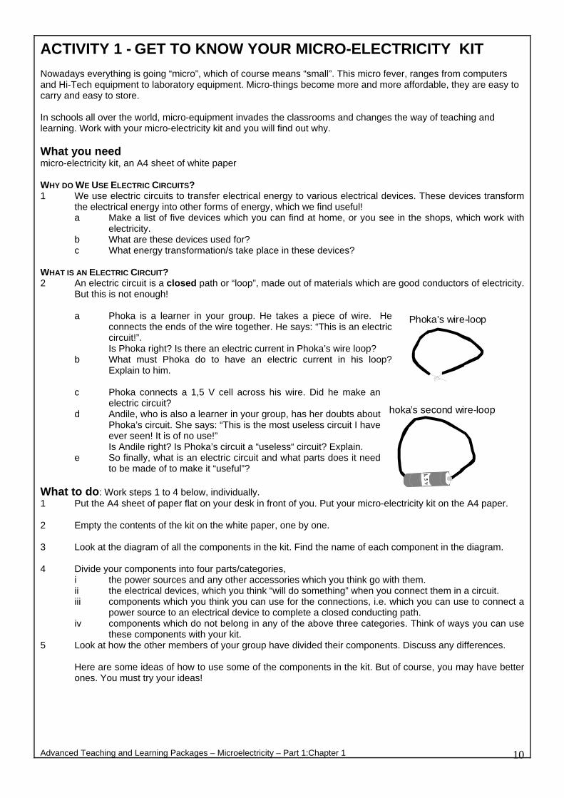
WHAT IS AN ELECTRIC CIRCUIT? 2 An electric circuit is a closed path or “loop”, made out of materials which are good conductors of electricity.
But this is not enough!
a Phoka is a learner in your group. He takes a piece of wire. He connects the ends of the wire together. He says: “This is an electric circuit!”. Is Phoka right? Is there an electric current in Phoka’s wire loop?
b What must Phoka do to have an electric current in his loop? Explain to him.
c Phoka connects a 1,5 V cell across his wire. Did he make an
electric circuit? d Andile, who is also a learner in your group, has her doubts about
Phoka’s circuit. She says: “This is the most useless circuit I have ever seen! It is of no use!”
P
Is Andile right? Is Phoka’s circuit a “useless“ circuit? Explain. e So finally, what is an electric circuit and what parts does it need
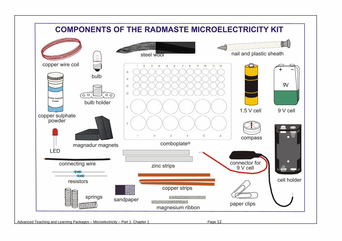
to be made of to make it “useful”? What to do: Work steps 1 to 4 below, individually. 1 Put the A4 sheet of paper flat on your desk in front of you. Put your micro-electricity kit on the A4 paper. 2 Empty the contents of the kit on the white paper, one by one. 3 Look at the diagram of all the components in the kit. Find the name of each component in the diagram. 4 Divide your components into four parts/categories,
i the power sources and any other accessories which you think go with them. ii the electrical devices, which you think “will do something” when you connect them in a circuit. iii components which you think you can use for the connections, i.e. which you can use to connect a
power source to an electrical device to complete a closed conducting path. iv components which do not belong in any of the above three categories. Think of ways you can use
these components with your kit. 5 Look at how the other members of your group have divided their components. Discuss any differences.
Here are some ideas of how to use some of the components in the kit. But of course, you may have better ones. You must try your ideas!
Advanced Teaching and Learning Packages – Microelectricity – Part 1:Chapter 1 10
Phoka’s wire-loop
hoka’s second wire-loop
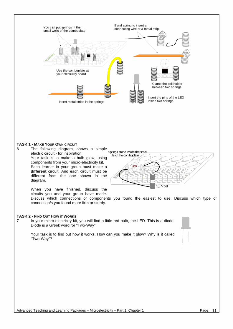
TASK 1 - MAKE YOUR OWN CIRCUIT 6 The following diagram, shows a simple
electric circuit - for inspiration! Your task is to make a bulb glow, using components from your micro-electricity kit.
we
Each learner in your group must make a different circuit. And each circuit must be different from the one shown in the diagram.
When you have finished, discuss the circuits you and your group have made. Discuss which connections or components you found the easiest to use. Discuss which type of connection/s you found more firm or sturdy.
TASK 2 - FIND OUT HOW IT WORKS 7 In your micro-electricity kit, you will find a little red bulb, the LED. This is a diode.
Diode is a Greek word for “Two-Way”.
Your task is to find out how it works. How can you make it glow? Why is it called “Two-Way”?
Advanced Teaching and Learning Packages – Microelectricity – Part 1: Chapter 1 Page 11
Springs stand inside the smalllls of the comboplate
1,5 V cell
You can put springs in thesmall wells of the comboplate
Use the comboplate asyour electricity board
Bend spring to insert aconnecting wire or a metal strip
Clamp the cell holderbetween two springs
Insert the pins of the LEDinside two springsInsert metal strips in the springs
Advanced Teaching and Learning Packages – Microelectricity – Part 1: Chapter 1 Page 12

ACTIVITY 2 - LIGHTEN UP, PREDICT AND EXPLORE What is electricity? What is an electric current? These are not easy questions, yet electricity is so much part of our lives. The more we learn about it, the more we learn to respect nature and the energy it provides us! In the past you made simple circuits and you learned how to light up a bulb. This Activity is nothing new, but hopefully it will challenge you to think, and refresh your memory ..... not bad for starters! What you need a micro-electricity kit PART A 1 The diagram alongside, shows what a bulb looks like
inside. 2 Predict which of the bulbs in the following figures will
light up. Work on your own. a Record your predictions in the table on the next page.
b Compare your predictions with those of other members of your group. Where you differ explain the reason
for your prediction. Make a group prediction and record it in the table on the next page. PART B 3 Test your group predictions using the micro-electricity kit equipment.
a Record your observations in the table on the next page. b Compare your observations with your predictions. Explain the results you observe. Add your
comments in the table on the next page.
Advanced Teaching and Learning Packages – Microelectricity – Part 1: Chapter 1 Page 13
filament
A B C
D
G
FE
J
IH
M
LK
N(1) (2)

4 To conclude, what is necessary to make a bulb light up?
TABLE
Bulb Your Prediction Group’s Prediction Observation Comments
A
B
C
D
E
F
G
H
I
J
K
L
M
N(1)
N(2)
Advanced Teaching and Learning Packages – Microelectricity – Part 1: Chapter 1 Page 14
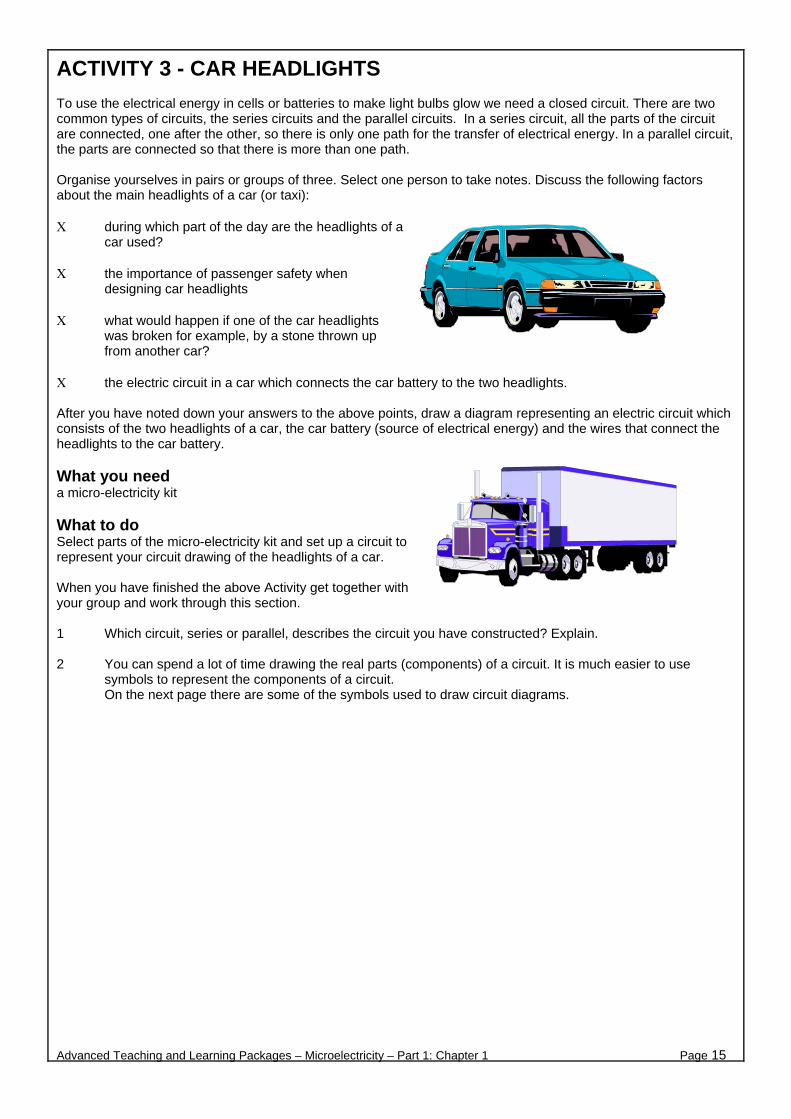
ACTIVITY 3 - CAR HEADLIGHTS To use the electrical energy in cells or batteries to make light bulbs glow we need a closed circuit. There are two common types of circuits, the series circuits and the parallel circuits. In a series circuit, all the parts of the circuit are connected, one after the other, so there is only one path for the transfer of electrical energy. In a parallel circuit, the parts are connected so that there is more than one path. Organise yourselves in pairs or groups of three. Select one person to take notes. Discuss the following factors about the main headlights of a car (or taxi): Χ during which part of the day are the headlights of a
car used? Χ the importance of passenger safety when
designing car headlights Χ what would happen if one of the car headlights
was broken for example, by a stone thrown up from another car?
Χ the electric circuit in a car which connects the car battery to the two headlights. After you have noted down your answers to the above points, draw a diagram representing an electric circuit which consists of the two headlights of a car, the car battery (source of electrical energy) and the wires that connect the headlights to the car battery. What you need a micro-electricity kit What to do Select parts of the micro-electricity kit and set up a circuit to represent your circuit drawing of the headlights of a car. When you have finished the above Activity get together with your group and work through this section. 1 Which circuit, series or parallel, describes the circuit you have constructed? Explain. 2 You can spend a lot of time drawing the real parts (components) of a circuit. It is much easier to use
symbols to represent the components of a circuit. On the next page there are some of the symbols used to draw circuit diagrams.
Advanced Teaching and Learning Packages – Microelectricity – Part 1: Chapter 1 Page 15
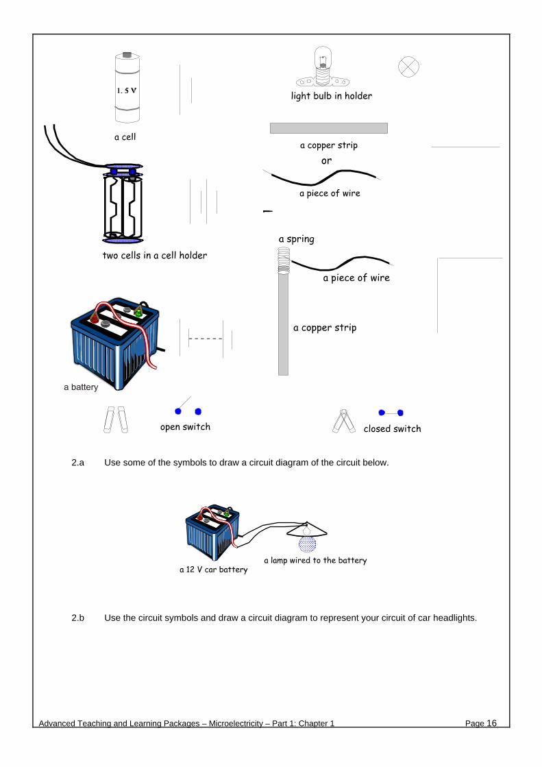
2.a Use some of the symbols to draw a circuit diagram of the circuit below.
2.b Use the circuit symbols and draw a circuit diagram to represent your circuit of car headlights.
Advanced Teaching and Learning Packages – Microelectricity – Part 1: Chapter 1 Page 16
ACTIVITY 4 - MAKING AN ELECTRIC CURRENT DETECTOR
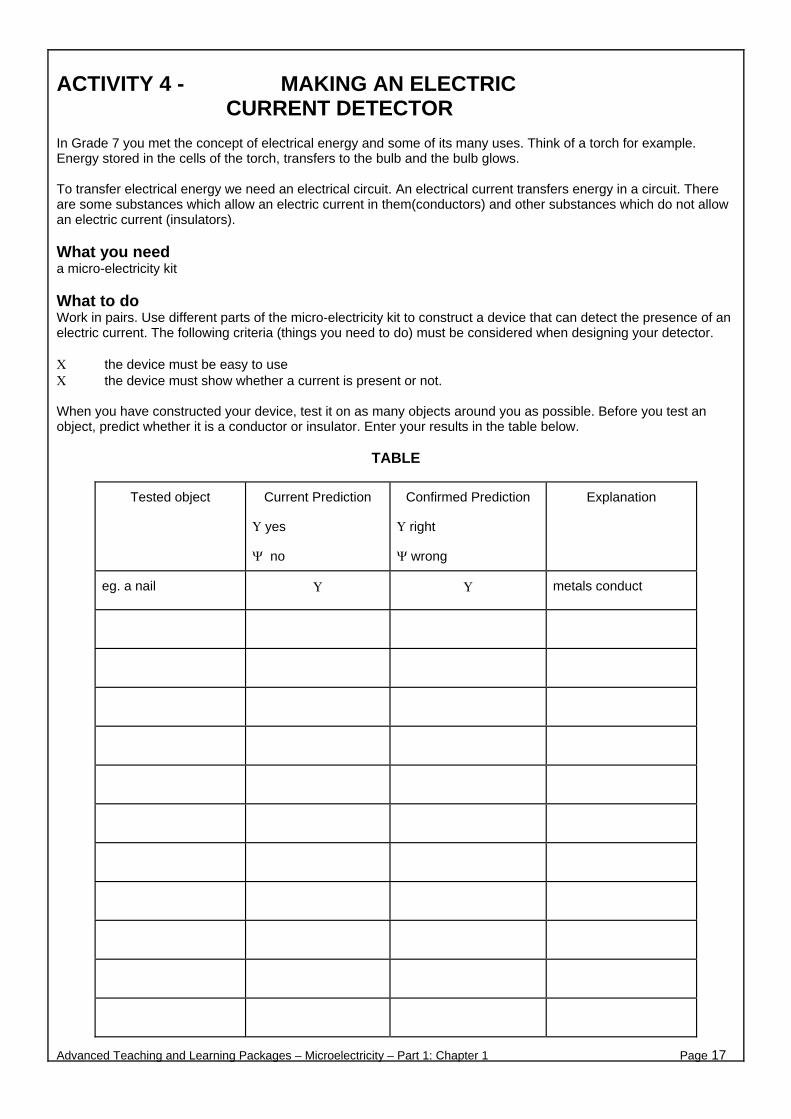
In Grade 7 you met the concept of electrical energy and some of its many uses. Think of a torch for example. Energy stored in the cells of the torch, transfers to the bulb and the bulb glows. To transfer electrical energy we need an electrical circuit. An electrical current transfers energy in a circuit. There are some substances which allow an electric current in them(conductors) and other substances which do not allow an electric current (insulators). What you need a micro-electricity kit What to do Work in pairs. Use different parts of the micro-electricity kit to construct a device that can detect the presence of an electric current. The following criteria (things you need to do) must be considered when designing your detector. Χ the device must be easy to use Χ the device must show whether a current is present or not. When you have constructed your device, test it on as many objects around you as possible. Before you test an object, predict whether it is a conductor or insulator. Enter your results in the table below.
TABLE
Tested object Current Prediction
Υ yes
Ψ no
Confirmed Prediction
Υ right
Ψ wrong
Explanation
eg. a nail Υ Υ metals conduct
Advanced Teaching and Learning Packages – Microelectricity – Part 1: Chapter 1 Page 17

What to discuss 1 Describe each part of your current detector and how it contributes to the working of the detector. 2 The objects that you tested today were all solids. Discuss whether some gases and liquids can conduct
electricity? If they do, could your detector be used to test these substances? Explain.
3 How do conductors and insulators make our day to day living easier and safer? Give at least four examples.
Advanced Teaching and Learning Packages – Microelectricity – Part 1: Chapter 1 Page 18

ACTIVITY 5 - THE CURRENT IN A SERIES CIRCUIT In a series circuit there is only one closed path for the current. The strength of the current is the same anywhere in the circuit. What you need a micro-electricity kit What to do Work in pairs or groups of three. Use the micro-electricity kit to construct the series circuits given in the figures below. Complete the given table. Remember to predict the brightness of the bulb before you close the switch.
Bulb’s position Brightness Prediction Bulb brightness
Before switch
After switch
Before battery
Advanced Teaching and Learning Packages – Microelectricity – Part 1: Chapter 1 Page 19
close the switch
position 1: before the switch
observe thebrightness ofthe bulb; writeobservation inthe table
close the switch position 3: before the battery observe the
brightness of thebulb; write observationin the table
close the switch position 2: after the switch
observe thebrightness of thebulb; write observationin the table
What to discuss 1 Thando is a Grade 8 learner. When he was asked by his teacher to describe the current in a series circuit
he said the following:
“The strength of the current before the light bulb is bigger. This is because the current goes through the light bulb and gets used up.”
Discuss Thando’s statement.
2 In your micro-electricity kit is a part called a resistor.
A resistor is a specially designed device to reduce the current in a circuit. Some parts of a circuit cannot work properly if they have large currents in them. If you ever get the chance, look inside a radio or TV. You will see many, many resistors.
Predict the brightness of the light bulb in your series circuit if you were to replace one of the copper strips with a resistor. Set up such a circuit and test your prediction. (You may need to add an LED to your series circuit.)
How accurate was your prediction? Discuss.
Advanced Teaching and Learning Packages – Microelectricity – Part 1: Chapter 1 Page 20
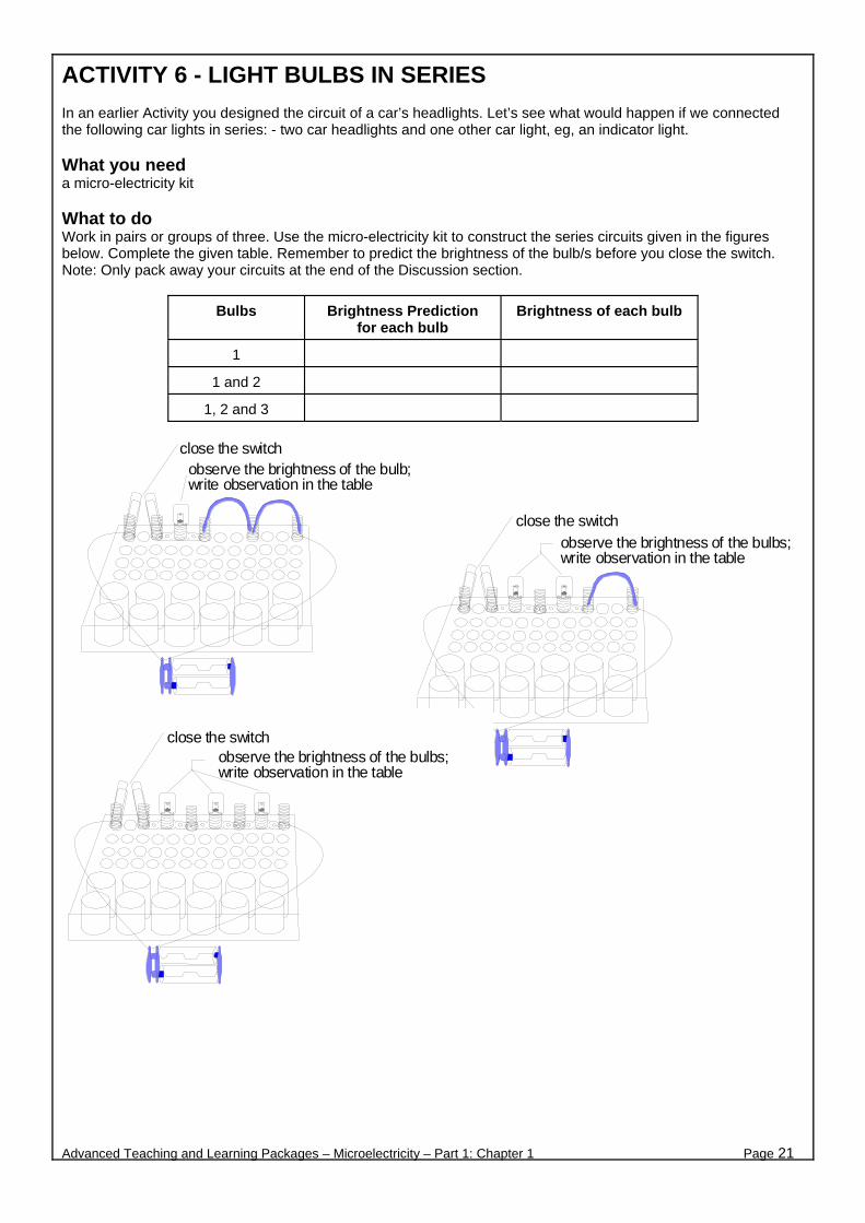
ACTIVITY 6 - LIGHT BULBS IN SERIES In an earlier Activity you designed the circuit of a car’s headlights. Let’s see what would happen if we connected the following car lights in series: - two car headlights and one other car light, eg, an indicator light. What you need a micro-electricity kit What to do Work in pairs or groups of three. Use the micro-electricity kit to construct the series circuits given in the figures below. Complete the given table. Remember to predict the brightness of the bulb/s before you close the switch. Note: Only pack away your circuits at the end of the Discussion section.
Bulbs Brightness Prediction for each bulb
Brightness of each bulb
1
1 and 2
1, 2 and 3
close the switch observe the brightness of the bulb;write observation in the table
Advanced Teaching and Learning Packages – Microelectricity – Part 1: Chapter 1 Page 21
close the switch observe the brightness of the bulbs;write observation in the table
close the switch observe the brightness of the bulbs;write observation in the table

What to discuss 1 Describe the changes of the brightness of the bulbs, in terms of electrical current, each time another bulb is
added in series. 2 In an earlier Activity you met an electrical device called a resistor.
a What similarities are there between the extra light bulbs added in series and the resistor.
We call the property of a substance that reduces current strength, resistance.
b Each light bulb has a certain resistance. Discuss, in terms of resistance, how the addition of each light bulb affects the current in a series circuit.
3 Predict what will happen if you unscrewed the first light bulb in the last series circuit you set up. Test your
prediction. Explain the result. 4 Let’s consider the possibility of connecting two car headlights and an indicator light in series. What
disadvantages and advantages would there be?
Advanced Teaching and Learning Packages – Microelectricity – Part 1: Chapter 1 Page 22

ACTIVITY 7 - LIGHT BULBS IN PARALLEL In an earlier Activity you met the circuit of car headlights. Car headlights are connected in parallel. Let’s look at the advantages of connecting the headlights in parallel. What you need a micro-electricity kit What to do Work in pairs or groups of three. 1 Use the micro-electricity kit to construct
the parallel circuit as shown on the right. 2 Predict whether the other bulbs will glow
if you unscrew one bulb. 3 Test your prediction. 4 Predict whether the other bulbs will glow
if you unscrew two bulbs. 5 Test your prediction. 6 Complete the given table.
Bulbs ‘Glow’ Prediction for each bulb ‘Glow’ of each bulb
Remove 1 bulb
Remove 2 bulbs What to discuss 1 How do light bulbs connected in parallel differ to light bulbs connected in series? 2 You are given some examples of some common circuits below:
Christmas tree lights, traffic lights (robots), torch, ceiling lights in the home, street lights; a Which circuits are parallel and which are series?
b Give the reasons for your choices. 3 COMPLETE THIS QUESTION ON YOUR OWN. After everyone has finished the questions compare
answers. If you disagree set up the circuits to check.
You are given some circuit diagrams. Chose the correct multiple choice answer for each.
a If the light bulb M suddenly “burns out”, what happens to light bulb N?
A It glows exactly as before B It glows brighter C It glows less bright D It does not glow
b Which bulb/s will glow with the same intensity (same brightness)? All
the bulbs are identical. A 1 and 2 B 2 and 3 C 1, 2 and 3 D 3 and 4
Advanced Teaching and Learning Packages – Microelectricity – Part 1: Chapter 1 Page 23
Copper or zinc stripsinserted in the springs
Close the switch
Remove one bulb, observeremove another bulb, observe
M
N
1 2 3
4

c Which bulb must be removed from the
circuit to make ALL the other bulbs go out? A 1 B 2 C 3 D 4
d Lebala, a Grade 8 learner connects three light bulbs called P, Q and R to two cells. Which circuit diagram corresponds exactly to the circuit she set up.
P
Advanced Teaching and Learning Packages – Microelectricity – Part 1: Chapter 1 Page 24
4
1
3
2
QR
R
Q
P
D
R
Q
P
A
R
Q
P
B
R
Q
P
C

ACTIVITY 8 - CELLS AND MORE CELLS Most torches work with two or even four cells connected together. Motor powered toys usually work with two cells. When we join two or more cells together, we get a battery of cells, or a battery. A cell is a portable source of electrical power. What is the difference between a cell and a battery? Let us discover some facts about cell connection. What you need a micro-electricity kit, prestik/plasticine, different kinds of torches if available (or other devices that work with batteries), multimeter 1 The diagram on the right, shows
several electrical devises, some of which are probably familiar to you. a Which of these devices have you used yourselves? b Which of these devises work with batteries? Discuss with your group.
2 Most of these devices need more than one 1,5 V cells to work. Is there any particular way to connect
several cells together, and how? What to do Form groups of 4 or 6 learners. Within your group work in pairs since you are going to use more cells than each kit provides. 1 Set up the circuit, as in the diagram on the right. 2 Connect the bare ends of the insulated wires to one cell.
Keep them in place with your fingers. Note and record the brightness of the bulb in the table on the next page.
a What potential difference (voltage) does a single
cell provide to your circuit? b Guess what should be the reading of a voltmeter connected across the bulb in your circuit? Record
your guess. tential difference across the bulb.
ble
o
ee
c Measure and record the pRecord your answers in thegiven on t
od ta
he next page. 3 Repeat ing tw
cells in
hr
step 2, this time connectseries.
4 Repeat step 2, this time connecting t
cells in series. First connect one cell,
then two cells,Prestik/plasticine to
then three cells keep cell in place
Advanced Teaching and Learning Packages – Microelectricity – Part 1: Chapter 1 Page 25
Portable radio
Personal Computer (P.C.) Lap top
calculator
Torch
Sewing machine
PhotographicCamera
Iron
Coffee machine
Side lamp
Bare ends ofinsulated wires
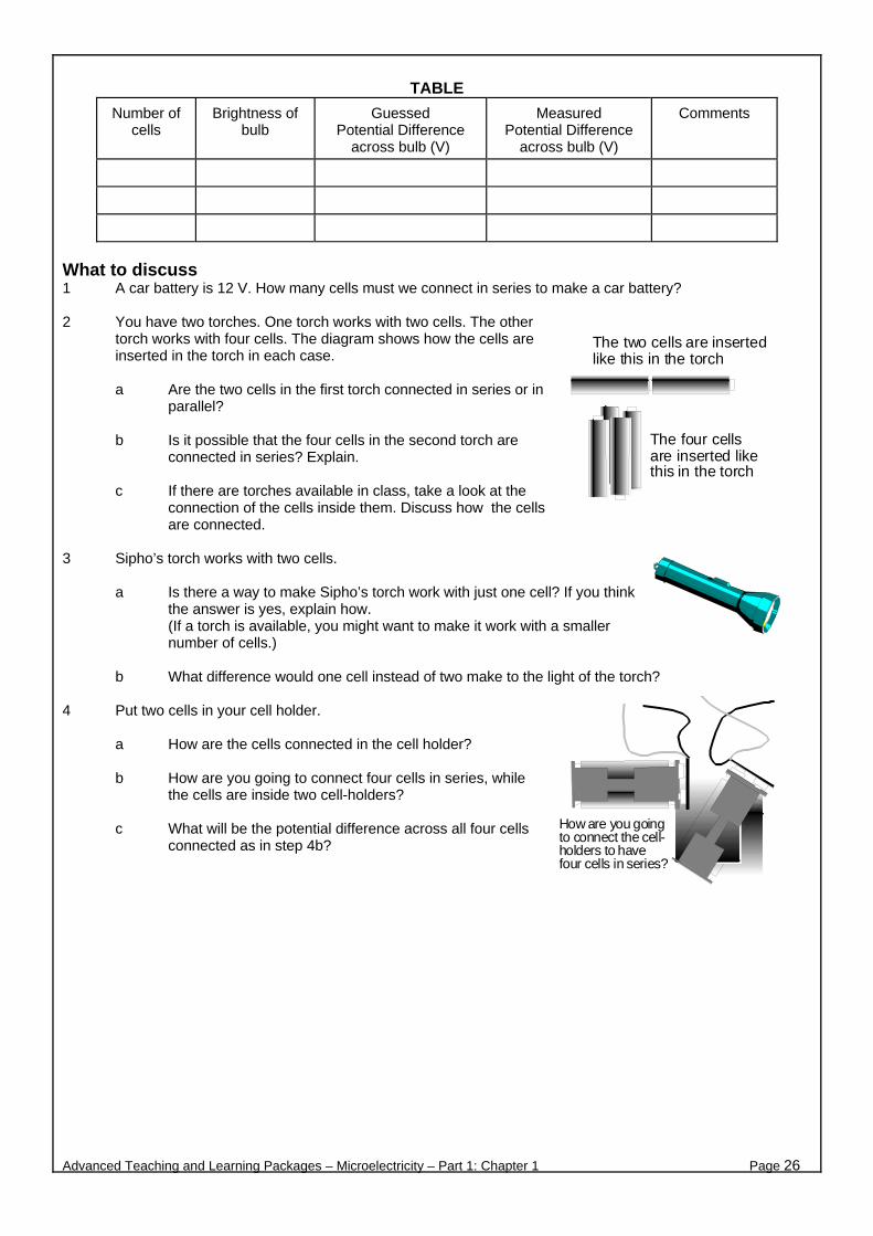
TABLE
Number of cells
Brightness of bulb
Guessed Potential Difference
across bulb (V)
Measured Potential Difference
across bulb (V)
Comments
What to discuss 1 A car battery is 12 V. How many cells must we connect in series to make a car battery?
2 You have two torches. One torch works with two cells. The other
torch works with four cells. The diagram shows how the cells are inserted in the torch in each case.
a Are the two cells in the first torch connected in series or in
parallel?
b Is it possible that the four cells in the second torch are connected in series? Explain.
c If there are torches available in class, take a look at the
connection of the cells inside them. Discuss how the cells are connected.
3 Sipho’s torch works with two cells.
a Is there a way to make Sipho’s torch work with just one cell? If you think the answer is yes, explain how. (If a torch is available, you might want to make it work with a smaller number of cells.)
b What difference would one cell instead of two make to the light of the torch?
4 Put two cells in your cell holder.
a How are the cells connected in the cell holder?
b How are you going to connect four cells in series, while the cells are inside two cell-holders?
c What will be the potential difference across all four cells
connected as in step 4b?
Advanced Teaching and Learning Packages – Microelectricity – Part 1: Chapter 1 Page 26
The two cells are insertedlike this in the torch
The four cellsare inserted likethis in the torch
How are you goingto connect the cell-holders to havefour cells in series?
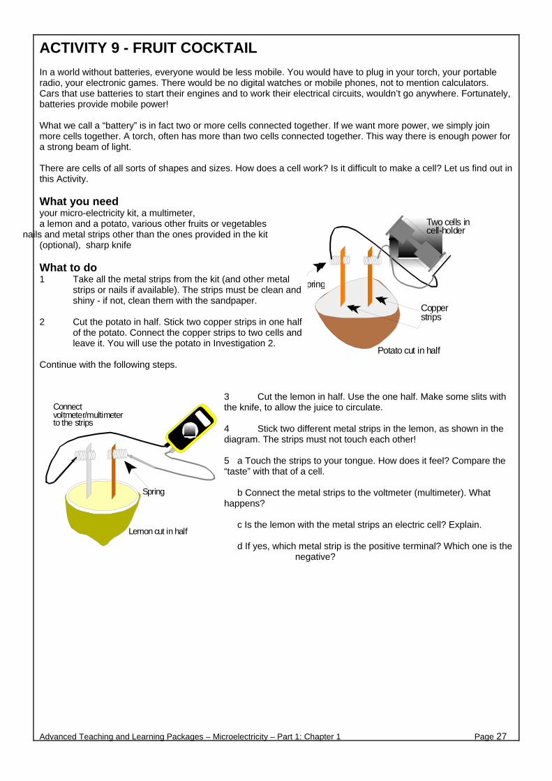
ACTIVITY 9 - FRUIT COCKTAIL In a world without batteries, everyone would be less mobile. You would have to plug in your torch, your portable radio, your electronic games. There would be no digital watches or mobile phones, not to mention calculators. Cars that use batteries to start their engines and to work their electrical circuits, wouldn’t go anywhere. Fortunately, batteries provide mobile power! What we call a “battery” is in fact two or more cells connected together. If we want more power, we simply join more cells together. A torch, often has more than two cells connected together. This way there is enough power for a strong beam of light. There are cells of all sorts of shapes and sizes. How does a cell work? Is it difficult to make a cell? Let us find out in this Activity. What you need your micro-electricity kit, a multimeter, a lemon and a potato, various other fruits or vegetables
nails and metal strips other than the ones provided in the kit (optional), sharp knife What to do 1 Take all the metal strips from the kit (and other metal
strips or nails if available). The strips must be clean and shiny - if not, clean them with the sandpaper.
2 Cut the potato in half. Stick two copper strips in one half
of the potato. Connect the copper strips to two cells and leave it. You will use the potato in Investigation 2.
Continue with the following steps.
3 Cut the lemon in half. Use the one half. Make some slits with the knife, to allow the juice to circulate. 4 Stick two different metal strips in the lemon, as shown in the diagram. The strips must not touch each other! 5 a Touch the strips to your tongue. How does it feel? Compare the “taste” with that of a cell. b Connect the metal strips to the voltmeter (multimeter). What happens? c Is the lemon with the metal strips an electric cell? Explain. d If yes, which metal strip is the positive terminal? Which one is the
negative?
Advanced Teaching and Learning Packages – Microelectricity – Part 1: Chapter 1 Page 27
Copperstrips
Potato cut in half
pring
Two cells incell-holder
Lemon cut in half
Connectvoltmeter/multimeterto the strips
Spring

INVESTIGATION No 1 6 Use different combinations of metal strips in the lemon. Also try strips of the same metal.
Use different fruits or vegetables. Each time connect the metal strips to the voltmeter. Record the reading.
7 Prepare a table to record: Χ the fruit or vegetable you use Χ the metals you use Χ the reading on the voltmeter Χ which metal strip is the positive terminal 8 a Which fruit and which combination of metal strips makes the strongest cell? Explain.
b Investigate how many of these cells must you connect in series to make the LED glow.
c Make a rough drawing, showing how you connect the cells to the LED. INVESTIGATION No 2 You need the potato with the two copper strips connected to a cell. 9 Look at the slits in the potato, where the copper strips are inserted. Note which strip is connected to the
positive, and which to the negative terminal of the cell. 10 Remove the copper strips from the potato to look inside the slits.
Compare the two slits. What do you see? 11 Maria wants to make a cell. She puts one magnesium and one copper strip in a lemon. Maria wants to
know which is the positive terminal of this cell.
Luckily you have a fresh potato and two copper strips. Help Maria to find out which is the positive terminal of her cell. Explain how you are going to do that!
12 Remember when you finish, to remove the strips from the fruits and to clean them!
Advanced Teaching and Learning Packages – Microelectricity – Part 1: Chapter 1 Page 28

B. EFFECTS OF THE ELECTRIC CURRENT
Advanced Teaching and Learning Packages – Microelectricity – Chapter 1 Page
29
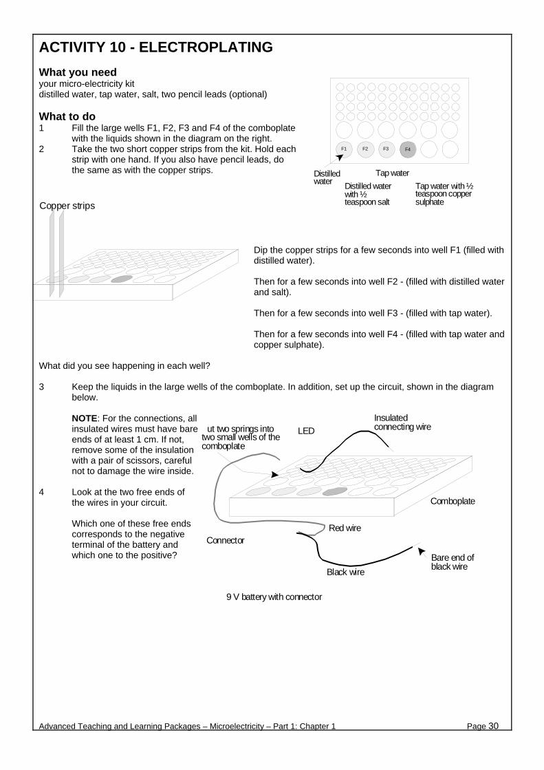
ACTIVITY 10 - ELECTROPLATING What you need your micro-electricity kit distilled water, tap water, salt, two pencil leads (optional) What to do 1 Fill the large wells F1, F2, F3 and F4 of the comboplate
with the liquids shown in the diagram on the right. 2 Take the two short copper strips from the kit. Hold each
strip with one hand. If you also have pencil leads, do the same as with the copper strips.
Dip the copper strips for a few seconds into well F1 (filled with distilled water). Then for a few seconds into well F2 - (filled with distilled water and salt). Then for a few seconds into well F3 - (filled with tap water). Then for a few seconds into well F4 - (filled with tap water and copper sulphate).
What did you see happening in each well? 3 Keep the liquids in the large wells of the comboplate. In addition, set up the circuit, shown in the diagram
below.
NOTE: For the connections, all insulated wires must have bare ends of at least 1 cm. If not, remove some of the insulation with a pair of scissors, careful not to damage the wire inside.
P
4 Look at the two free ends of
the wires in your circuit.
Which one of these free ends corresponds to the negative terminal of the battery and which one to the positive?
Advanced Teaching and Learning Packages – Microelectricity – Part 1: Chapter 1 Page 30
F1 F2 F3 F4
Tap water with ½teaspoon coppersulphate
Tap water
Distilled waterwith ½teaspoon salt
Distilledwater
Copper strips
LED
Connector
Comboplate
Red wire
9 V battery with connector
Black wire
Insulatedconnecting wireut two springs into
two small wells of thecomboplate
Bare end ofblack wire

5 Take the two copper strips
again. This time, touch the copper strips to the free bare ends of the wires. (You can use springs to attach the wires to the copper strips, as shown in the diagram.)
Repeat step 2. Record what you see happening in each well.
Write your observations in the table below.
TABLE
What did you see? Well
Solution
LED Does it glow?
Negative terminal Positive terminal
F1
F2
F3
F4
What to discuss 1 What is the difference between distilled water and tap water? 2 In which well/s did you not see any change? 3 What caused the changes you observed in the wells? 4 a Why do we have an LED connected to the circuit?
b In this Activity, which solutions (and in which wells) conduct an electric current? c Is distilled water an insulator or a conductor?
5 In this Activity, you observed the effect of an electric current as it passed through several materials.
a What kind of effect was that? Chose the best answer from the list below. Explain your answer to the others in your group. (i) a heating effect (ii) a magnetic effect (iii) a chemical effect (iv) other effect (specify)
b In this Activity, on which materials (the metal strips; the solutions) did the electric current have an
effect? 6 What would you do to make an ugly old key look like new with copper or another metal coating? What else
would you like to electroplate?
Advanced Teaching and Learning Packages – Microelectricity – Chapter 1 Page
31
LED
Copper stripsmust not touch

ACTIVITY 11 - COMING ATTRACTION What you need your micro-electricity kit What to do 1 Prepare a circuit, as shown in the
diagram on the right. Use a 3 V battery. Do not connect the bare ends of the insulated wires yet!
2 Put the magnetic compass at different
positions around the wires and the other components of the circuit. The diagram below gives some examples of where to put the compass.
At each new position of the compass, wait until the pointer stops shaking, and then touch the bare ends of the insulated wires. Complete the table below with your observations.
Position of magnetic compass Observations
On top of (black) negative wire
Under negative wire
Next to negative wire
On top of (red) positive wire
Under positive wire
Next to positive wire
On top of the bulb
Next to bulb
On top of the battery
Next to battery
Other (specify)
Advanced Teaching and Learning Packages – Microelectricity – Part 1: Chapter 1 Page 32
Straightinsulated wire
Put the compass at differentpositions around the circuit

3 Put the magnetic compass under the straight black insulated wire, as in the diagram on the right. Note that the straight black insulated wire is on top and parallel to the pointer of the compass. (You might have to turn the whole comboplate until you achieve this orientation.)
Connect the bare ends of the insulated wires and look at the pointer of the compass. Record what happens.
4 Now reverse the wires from the battery as in the diagram on the left. a Before you close the circuit, predict which one of the following will happen to the pointer. Explain your prediction to the others in the group. i the pointer will not deflect this time ii the pointer will deflect the same as in 3 iii the pointer will deflect in the opposite direction of that in 3 b Connect the bare ends of the insulated wires and
look at the pointer of the compass. Record what happens. Compare your observations with 3.
What to discuss 1 a In which positions around the circuit did the pointer of the magnetic compass deflect the most?
b In which positions did you not notice a deflection?
c When the circuit was incomplete, that is, when you did not touch the bare ends of the wires, did you see any deflection of the compass pointer at any position?
2 What would be the difference in your observations, if you were to use the 9 V battery instead of the 3V
battery? You may try it. 3 In general, what deflects a magnetic compass? 4 What causes the magnetic compass to deflect in this Activity? 5 In conclusion, as far as you saw in this Activity, what is the connection between an electric current and
magnetism? Discuss with your group and write it down. The spokesperson of your group will present it to the rest of the class.
Advanced Teaching and Learning Packages – Microelectricity – Part 1: Chapter 1 Page 33
Bare ends ofinsulated wires
Black
Red
This wire is on top ofthe compass and it isparallel to the pointer
Bare ends ofinsulated wires
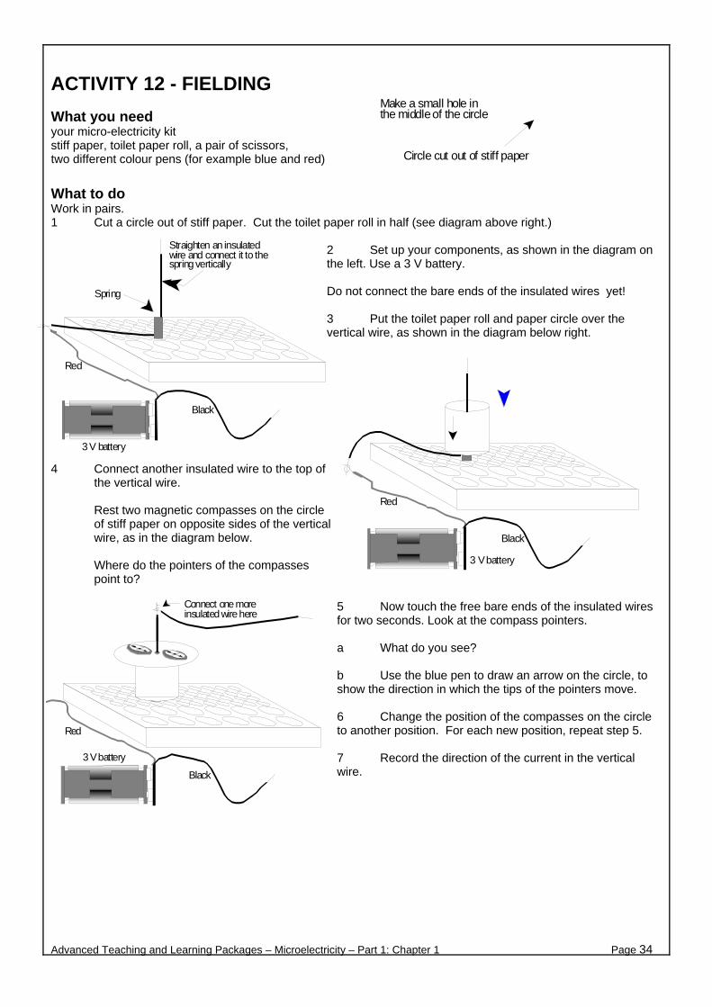
ACTIVITY 12 - FIELDING What you need your micro-electricity kit stiff paper, toilet paper roll, a pair of scissors, two different colour pens (for example blue and red)
What to do Work in pairs. 1 Cut a circle out of stiff paper. Cut the toilet paper roll in half (see diagram above right.)
2 Set up your components, as shown in the diagram on the left. Use a 3 V battery. Do not connect the bare ends of the insulated wires yet! 3 Put the toilet paper roll and paper circle over the vertical wire, as shown in the diagram below right.
4 Connect another insulated wire to the top of the vertical wire.
Rest two magnetic compasses on the circle of stiff paper on opposite sides of the vertical wire, as in the diagram below.
Where do the pointers of the compasses point to?
5 Now touch the free bare ends of the insulated wires for two seconds. Look at the compass pointers. a What do you see? b Use the blue pen to draw an arrow on the circle, to show the direction in which the tips of the pointers move. 6 Change the position of the compasses on the circle to another position. For each new position, repeat step 5. 7 Record the direction of the current in the vertical wire.
Advanced Teaching and Learning Packages – Microelectricity – Part 1: Chapter 1 Page 34
Circle cut out of stiff paper
Make a small hole inthe middle of the circle
Red
Black
3 V battery
Straighten an insulatedwire and connect it to thespring vertically
Spring
Red
Black
3 V battery
Red
Black
3 V battery
Connect one moreinsulated wire here
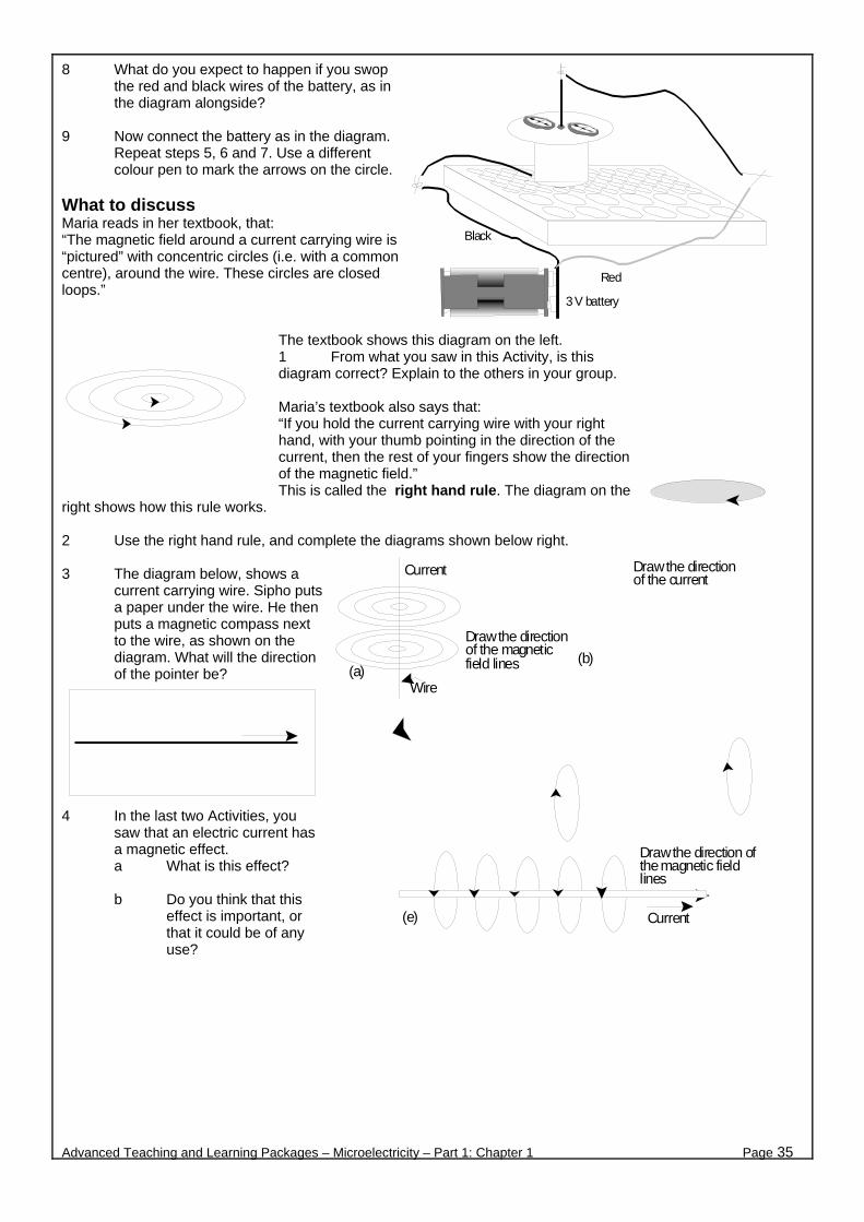
8 What do you expect to happen if you swop the red and black wires of the battery, as in the diagram alongside?
9 Now connect the battery as in the diagram.
Repeat steps 5, 6 and 7. Use a different colour pen to mark the arrows on the circle.
What to discuss Maria reads in her textbook, that: “The magnetic field around a current carrying wire is “pictured” with concentric circles (i.e. with a common centre), around the wire. These circles are closed loops.”
The textbook shows this diagram on the left. 1 From what you saw in this Activity, is this diagram correct? Explain to the others in your group. Maria’s textbook also says that: “If you hold the current carrying wire with your right hand, with your thumb pointing in the direction of the current, then the rest of your fingers show the direction of the magnetic field.” This is called the right hand rule. The diagram on the
right shows how this rule works. 2 Use the right hand rule, and complete the diagrams shown below right. 3 The diagram below, shows a
current carrying wire. Sipho puts a paper under the wire. He then puts a magnetic compass next to the wire, as shown on the diagram. What will the direction of the pointer be?
4 In the last two Activities, you saw that an electric current has a magnetic effect. a What is this effect?
b Do you think that this
effect is important, or that it could be of any use?
Advanced Teaching and Learning Packages – Microelectricity – Part 1: Chapter 1 Page 35
Red
Black
3 V battery
Current
Draw the directionof the magneticfield lines
Wire(a)
Draw the directionof the current
(b)
Current
Draw the direction ofthe magnetic fieldlines
(e)

ACTIVITY 13 - THE STRONGEST OF THEM ALL! What you need your micro-electricity kit, steel nail or steel paper clips, small steel pins or iron filings, prestik/plasticine What to do Note: In your micro-electricity kit you will find a coil of copper wire. This
copper wire is coated. You must remove the coating from both ends of the wire. You do this by rubbing the ends with the sand paper.
1 Prepare the set up shown in the diagram on
the right. Stand the coil vertically on the desk. Place the compass inside the coil. a Where does the pointer of the
compass point to?
b Connect the free end of the coil, to the right (as in diagram) spring. Where does the pointer of the compass point to this time?
c Disconnect the ends of the coil from the springs, and connect them the other way round. Where does the pointer of the compass point to this time?
2 In your micro-electricity kit, you have a
piece of plastic straw. Wind about half the length of the copper wire around the straw. Do not cut the rest of the copper wire!
Lie the straw on your desk. Note: The windings must be in the same direction!
3 Connect the ends of the copper wire to your circuit, as in the diagram on the left. a Bring the compass close to the straw at different positions. What happens? b Move one the end of the straw close to the pins. What happens?
Advanced Teaching and Learning Packages – Microelectricity – Part 1: Chapter 1 Page 36
Sand-paper theends of the copperwire
Coil of copper wire
Red
Black
Prestik or plasticine to keepthe coil vertical on the desk
Wind half the copper wirearound the straw
Do not cut therest of the wire
Bare ends ofcopper wire
Straw
Red
Black3V battery
Steel pins
Compass

4 Now, insert the iron nail inside
the straw, as shown in the diagram on the right. a Bring the compass
close to the straw. What happens?
b Move one end of the
straw close to the pins. What happens?
5 Disconnect the copper wire
from the springs. Wind some more wire around the straw. Repeat steps 3 and 4.
6 Replace the iron nail with the steel nail or straightened paper clips. Repeat steps 3 and 4. If you have steel paper clips, straighten up two of them and insert them in the straw. You may also try the same thing with some of the strips in your kit. Record your observations in a table. What to discuss
A coil of wire, like the copper wire wound around an empty straw, is called a solenoid. The word “solenoid” is a Greek word meaning “hollow pipe”. If you put an iron bar inside the solenoid, you have an electromagnet. 1 In this Activity, you inserted an iron nail inside your solenoid. The solenoid with the nail is an
electromagnet. a Do you think this name is suitable? Explain. b Does a solenoid connected to a battery produce a magnetic field around it? Explain. c In this Activity, how did you make a stronger electromagnet?
2 If you were to use the 9 V battery instead of the 3 V battery you used in this Activity, how do you think this
change would affect your electromagnet? 3 Sibongile reads in her text book : “An electromagnet is similar to a bar magnet.”
Sibongile asks: “Then where is the south and north pole of the electromagnet?” a Explain to Sibongile how to find the north and south pole of an electromagnet. b How can you change the north and south poles of your electromagnet?
4 Diagram A, shows the magnetic field lines
around a bar magnet. Their direction outside the magnet, is always due south. With the help of diagram A, find the north and south poles of the electromagnet shown in the diagram B. (Hint: Use the right hand rule).
5 In conclusion, which factors affect the strength
of your electromagnet?
Advanced Teaching and Learning Packages – Microelectricity – Part 1: Chapter 1 Page 37
Red
Black3V battery
Steel pins
CompassPut the iron nail inside the straw
Wind more copper wirearound the straw
Leave enough wirefor the connections
SouthNorth
CHAPTER 2
CURRENT ELECTRICITY
Advanced Teaching and Learning Packages – Microelectricity – Part 1: Chapter 2 Page 38
ACTIVITY 1 - RATES AND FLOWS INTRODUCTION We all know what we can do with electricity. Once we get electricity at home, we can’t live without it! But what is an electric current? ELECTRIC CURRENT - An electric current has to do with moving electric charges. But, this is not enough! When charges move in random directions we do not have a current. It is only when the charges move, overall, in the same direction, i.e. when the charge “flows”, that we can start thinking of current. We are nearly there! An electric current is how fast or how quickly the charge flows. MIND YOUR LANGUAGE! - We could say: “Current is the quickness of flow”, but we use the word “rate” instead which means the same, how fast. So, electric current is the “Flow Rate” of the electric charge.
“An electric current is not the movement of charge. An electric current is not the flow of charge. An electric current is the rate of flow of charge.”
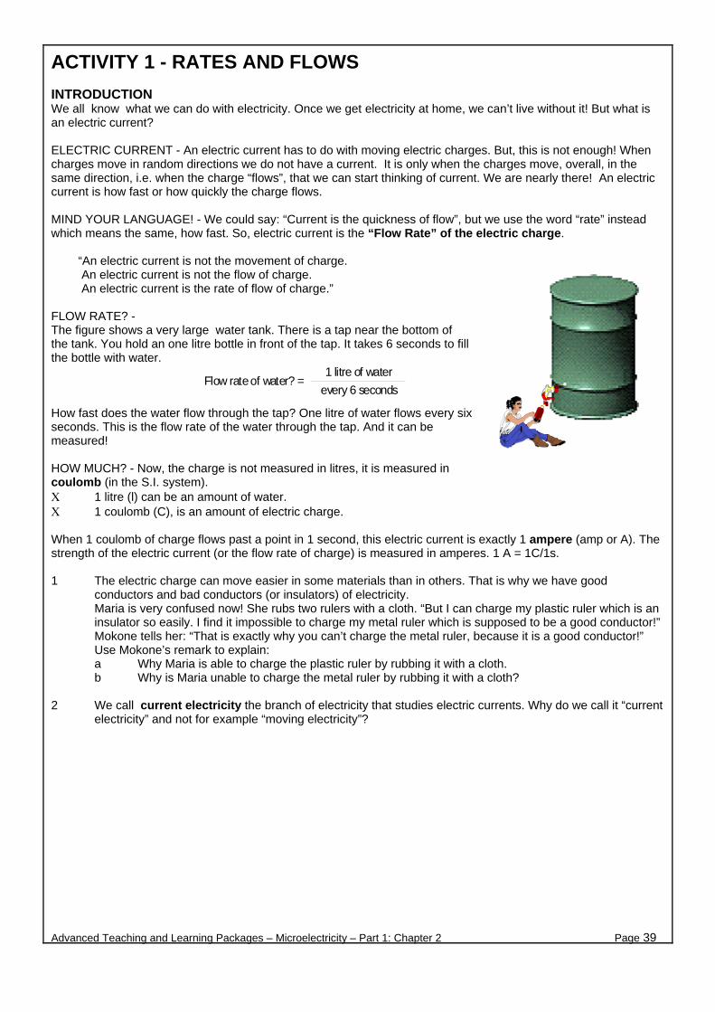
FLOW RATE? - The figure shows a very large water tank. There is a tap near the bottom of the tank. You hold an one litre bottle in front of the tap. It takes 6 seconds to fill the bottle with water. How fast does the water flow through the tap? One litre of water flows every six seconds. This is the flow rate of the water through the tap. And it can be measured! HOW MUCH? - Now, the charge is not measured in litres, it is measured in coulomb (in the S.I. system). Χ 1 litre (l) can be an amount of water. Χ 1 coulomb (C), is an amount of electric charge. When 1 coulomb of charge flows past a point in 1 second, this electric current is exactly 1 ampere (amp or A). The strength of the electric current (or the flow rate of charge) is measured in amperes. 1 A = 1C/1s. 1 The electric charge can move easier in some materials than in others. That is why we have good
conductors and bad conductors (or insulators) of electricity. Maria is very confused now! She rubs two rulers with a cloth. “But I can charge my plastic ruler which is an insulator so easily. I find it impossible to charge my metal ruler which is supposed to be a good conductor!” Mokone tells her: “That is exactly why you can’t charge the metal ruler, because it is a good conductor!” Use Mokone’s remark to explain: a Why Maria is able to charge the plastic ruler by rubbing it with a cloth. b Why is Maria unable to charge the metal ruler by rubbing it with a cloth?
2 We call current electricity the branch of electricity that studies electric currents. Why do we call it “current
electricity” and not for example “moving electricity”?
Advanced Teaching and Learning Packages – Microelectricity – Part 1: Chapter 2 Page 39
1 litre of water
every 6 secondsFlow rate of water? =

3 Look at the three pairs of diagrams below.
Diagram (a) - The people are waiting in the queue to submit an application form. There is only one employee to attend to them.
Diagram (b) - This is the same queue of people. This time there are three employees to attend to them.
Diagram (c) - The river flows in the valley. Diagram (d) - Along the river there is a waterfall.
Diagram (e) - A bulb is connected to a cell. The bulb glows.
Diagram (f) - The same bulb is connected to two cells. This time, the bulb glows brighter.
a What is common between the three pairs of diagrams? b What flows in each pair of diagrams? c In each pair of diagrams, explain what causes the flow to change.
4 Give two other examples of flowing things. Explain how to increase their flow. DESIGN AN INVESTIGATION 5 Sipho does not understand the concept of flow rate. Therefore, he cannot understand what current
is. Luckily you are here to help him!
LEARNING BY DOING! - To help Sipho, you can design an activity that models flow rates, like: Investigating salt running out of a hole at the bottom of a paper cup.
But first, you must design the activity. Your activity must be planned in such a way that:
C Sipho measures the flow rate of salt C Sipho predicts factors that could change the flow rate of salt C Sipho puts his predictions to test Before you start designing the activity, consider the different steps taken during an investigation. Use these steps to guide you. If the materials are available, at the end of the Activity you can do a role play of your activity for the other groups in class. One person from your group will be Sipho, the others will guide him and challenge him with questions.
Advanced Teaching and Learning Packages – Microelectricity – Part 1: Chapter 2 Page 40
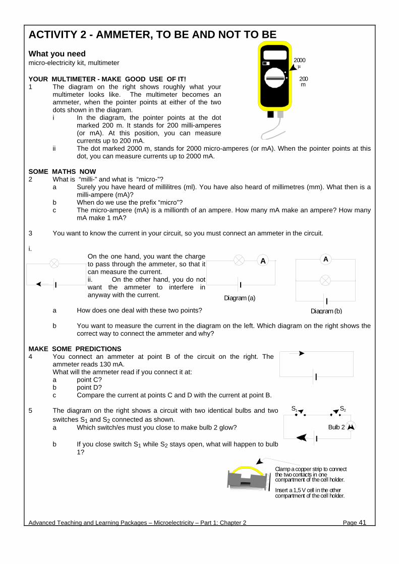
ACTIVITY 2 - AMMETER, TO BE AND NOT TO BE What you need micro-electricity kit, multimeter YOUR MULTIMETER - MAKE GOOD USE OF IT! 1 The diagram on the right shows roughly what your
multimeter looks like. The multimeter becomes an ammeter, when the pointer points at either of the two dots shown in the diagram. i In the diagram, the pointer points at the dot
marked 200 m. It stands for 200 milli-amperes (or mA). At this position, you can measure currents up to 200 mA.
ii The dot marked 2000 m, stands for 2000 micro-amperes (or mA). When the pointer points at this dot, you can measure currents up to 2000 mA.
SOME MATHS NOW 2 What is “milli-” and what is “micro-”?
a Surely you have heard of millilitres (ml). You have also heard of millimetres (mm). What then is a milli-ampere (mA)?
b When do we use the prefix “micro”? c The micro-ampere (mA) is a millionth of an ampere. How many mA make an ampere? How many
mA make 1 mA? 3 You want to know the current in your circuit, so you must connect an ammeter in the circuit. i.
On the one hand, you want the charge to pass through the ammeter, so that it can measure the current. ii. On the other hand, you do not want the ammeter to interfere in anyway with the current.
a How does one deal with these two points?
b You want to measure the current in the diagram on the left. Which diagram on the right shows the
correct way to connect the ammeter and why?
MAKE SOME PREDICTIONS 4 You connect an ammeter at point B of the circuit on the right. The
ammeter reads 130 mA. What will the ammeter read if you connect it at: a point C? b point D? c Compare the current at points C and D with the current at point B.
5 The diagram on the right shows a circuit with two identical bulbs and two
switches S1 and S2 connected as shown. a Which switch/es must you close to make bulb 2 glow?
b If you close switch S1 while S2 stays open, what will happen to bulb
1?
Advanced Teaching and Learning Packages – Microelectricity – Part 1: Chapter 2 Page 41
2000 µ
200 m
AA
Diagram (a)
Diagram (b)
S1 S2
Bulb 2
Clamp a copper strip to connectthe two contacts in onecompartment of the cell holder.
Insert a 1,5 V cell in the othercompartment of the cell holder.

TEST YOUR PREDICTIONS A USEFUL TIP: The cell holder is designed to hold two 1,5 V cells. If you want to use one cell only, you can still use the cell holder. The diagram on the right shows one way. Of course you may have better ideas.... 6 In question 4, you compared the current at points C and D with the current at point B. Test this prediction
using components from the micro-electricity kit. Use only one 1,5 V cell. 7 Use components from your micro-
electricity kit to prepare the circuit shown in the diagram on the right. a Use this circuit to test your
predictions in question 5. How will you simulate the action of the switches S1 and S2?
b Compare your observations with
your predictions. If there is conflict, explain.
c Remove one bulb (or just unscrew
it) from the circuit. What happens to the other bulb? Explain.
8 Work with the circuit you have just made, but use only one 1,5 V cell.
a Use the multimeter to measure the current: i on the left of bulb 1 ii between bulbs 1 and 2 iii on the right of bulb 2 In between measurements switch the ammeter off. Record your measurements in a table. When you finish, don’t forget to disconnect the cell. b Compare the three currents you have just measured. What is your conclusion?
9 The diagrams on the right, represent the circuits you set up in question 6 and in question 8 respectively.
Compare these two circuits. Compare what you have measured and observed. What conclusions can you draw from the information?
Advanced Teaching and Learning Packages – Microelectricity – Part 1: Chapter 2 Page 42
Two 1,5 V cells inthe cell-holder
A
B C D E
F
Copper or zinc stripsinserted in springs
Clamp a copper strip to connect the two contacts inone compartment of the cell holder.
Insert a 1,5 V cell in the other compartment of thecell holder.
To read current, setpointer at 200 mA
Multimeter
A
B C D E
F
Strip 3Strip 2Strip 1 Bulb 1 Bulb 2
I
Bulb
Cell
I’
Bulb 1
Cell
Bulb 2

ACTIVITY 3 - GO WITH THE FLOW Electrons were discovered in the 1890's. Rutherford’s “planetary” model of the atom was introduced around 1911. Does this mean that this was the beginning of electricity? Not at all! At least a century before that, people knew of the existence of two kinds of charge, positive and negative. Volta’s battery was made known in the year 1800. There were electric circuits before the discovery of the electron. But, scientists assumed that it was the positive charge that was flowing in the wires. Today we know a great deal about the structure of metals, so we know that it is the negative charge (the free electrons) that flows in the wires of an electric circuit. However, even today, when we draw an electric circuit, we represent the electric current as an arrow starting at the positive terminal of the cell. It looks as if the current in the circuit is the flow of positive charge. This is what we call the conventional electric current. In electricity, whenever we use the word “current” we mean the “conventional current”. Why do we still use the conventional current today? We know that this is not the real current. The real current is the flow of negative charge, which flows in the opposite direction. Does this “convention” affect our results? Let’s find out in this Activity! What you need Three A4 sheets of transparent material, like overhead transparencies, pens to write on the transparent sheets, sticky tape, cardboard, a pair of scissors, ruler, white paper to cover the desk, overhead projector (optional) What to do 1 Make a frame out of cardboard. Roughly follow the dimensions shown
in the diagram above right. A
2 Take an A4 transparent sheet. Draw positive charges in regular
positions, as shown in the diagram on the right. 3 Stick the frame over the sheet with the positive charges, as shown in
the diagram on the right. 4 Connect two A4 transparent sheets edge to edge, to make a long
sheet. Draw free electrons in random places, as shown in the diagram below.
5 Cover your desk with white paper.
Advanced Teaching and Learning Packages – Microelectricity – Part 1: Chapter 2 Page 43
Real current
I
Conventional current
4 sheet with positive charges
Negative charges - free electrons
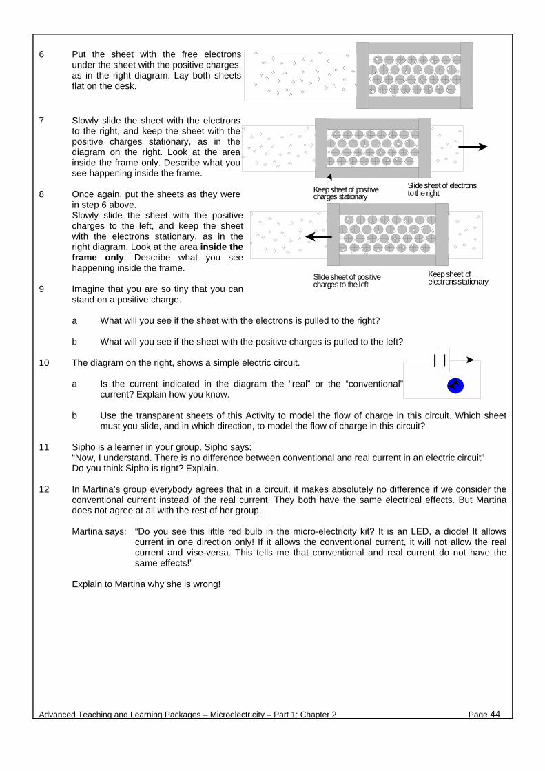
6 Put the sheet with the free electrons
under the sheet with the positive charges, as in the right diagram. Lay both sheets flat on the desk.
7 Slowly slide the sheet with the electrons to the right, and keep the sheet with the positive charges stationary, as in the diagram on the right. Look at the area inside the frame only. Describe what you see happening inside the frame.
8 Once again, put the sheets as they were
in step 6 above. Slowly slide the sheet with the positive charges to the left, and keep the sheet with the electrons stationary, as in the right diagram. Look at the area inside the frame only. Describe what you see happening inside the frame.
9 Imagine that you are so tiny that you can
stand on a positive charge.
a What will you see if the sheet with the electrons is pulled to the right?
b What will you see if the sheet with the positive charges is pulled to the left? 10 The diagram on the right, shows a simple electric circuit.
a Is the current indicated in the diagram the “real” or the “conventional” current? Explain how you know.
b Use the transparent sheets of this Activity to model the flow of charge in this circuit. Which sheet
must you slide, and in which direction, to model the flow of charge in this circuit? 11 Sipho is a learner in your group. Sipho says:
“Now, I understand. There is no difference between conventional and real current in an electric circuit” Do you think Sipho is right? Explain.
12 In Martina’s group everybody agrees that in a circuit, it makes absolutely no difference if we consider the
conventional current instead of the real current. They both have the same electrical effects. But Martina does not agree at all with the rest of her group.
Martina says: “Do you see this little red bulb in the micro-electricity kit? It is an LED, a diode! It allows
current in one direction only! If it allows the conventional current, it will not allow the real current and vise-versa. This tells me that conventional and real current do not have the same effects!”
Explain to Martina why she is wrong!
Advanced Teaching and Learning Packages – Microelectricity – Part 1: Chapter 2 Page 44
Slide sheet of electronsto the rightKeep sheet of positive
charges stationary
Keep sheet ofelectrons stationary
Slide sheet of positivecharges to the left

ACTIVITY 4 - ONE, TWO, THREE, ...... TROUBLE! What you needmicro-electricity kit, multimeter, graph paper What to do Work in groups of two or three. Work with one circuit per group and combine the components of your kits when necessary. HELP JOE, AND TEST YOUR KNOWLEDGE 1 Joe’s little sister asked him to put three lights in her doll-house. Joe is a beginner in electricity. He knows
that to get an electric current, he needs a closed conducting path and a source of power. Joe tries, using components from his micro-electricity kit. The diagram above shows how Joe connected his three bulbs with one 1,5 V cell.
Joe is absolutely sure that his circuit is correct. He double-checked all the connections, the bulbs are new, the cell is new. But the bulbs don’t glow! He tells you: “I don’t understand why I can’t get a current!”
Help Joe! Is there something wrong with the connections? Is there a current in Joe’s circuit? Does Joe need to change his circuit? Show him what to do, using components from your micro-electricity kit.
2 Joe is grateful. He manages to make his bulbs glow! Which one of the three diagrams below, shows the
changes Joe made? Explain why.
. 3 Joe’s sister is very pleased with the glowing bulbs in her doll-house. But now she wants a very bright light
for the lounge (of the doll-house)! “I want it VERY bright!”, she tells her brother. “Leave it to me, that’s easy to do”, says Joe.
The diagram on the right shows what Joe did this time. And guess what, Joe’s bulb does not glow! What did he do wrong this time?
Help Joe, once more. a Is there something wrong with the connections?
Are the batteries wrongly connected? Are the batteries connected in series or in parallel? Is there a current in Joe’s circuit? What has likely gone wrong?
b Draw a circuit diagram of Joe’s circuit.
Advanced Teaching and Learning Packages – Microelectricity – Part 1: Chapter 2 Page 45
1,5 V cell
Metal strips
Diag. 1 Diag. 2 Diag. 3
9 V batteries withconnectors
Connectingwires from thebatteries areclamped into aspring
Red wire
Black wire

SOMETHING FOR YOU TO THINK ABOUT Most electrical devices, like the resistors in your kit, can be represented by either of the symbols shown on the left. Representing components with symbols, saves time when drawing an electric circuit!
4 Consider the two diagrams (diagram A and B) on the right. In which diagram, (explain your answers) a is the electric current greater? b is the number of flowing charges greater? c is the potential difference across the resistors greater? d is the electric energy transferred to the resistors greater?
5 An electronics technician, measures the
electric current and the potential difference across an electrical device in a simple electric circuit. The diagram on the left shows this
circuit. Which of the diagrams on the right, show the correct use of the ammeter and voltmeter? Explain.
INVESTIGATE In the following investigation you will connect from one up to four cells in series. To connect the cells, use cell-holder/s. How will you do this? 6 Use components from the micro-electricity kit, to set up the components, shown in the next diagram.
Initially you will connect a single cell (see diagram) to complete the circuit. a Decide amongst your group, how and
where to connect the ammeter and the voltmeter. If you use a multimeter instead, take these measurements one at a time. Measure:
Χ the current in the circuit and Χ the potential difference across the resistor.
b Record your measurements in a table. Repeat steps a and b with two cells connected in series, then with three and finally with four cells.
7 Plot a graph of potential difference (V), versus the current (I), on graph paper. 8 Use your graph to explain or answer the following questions:
a What happens to the current in an electric circuit, when you connect more cells in series? How is this represented on your graph?
b What is the relationship between potential difference and current? (What do we call this type of relationship?)
c Use the graph to estimate the current, when the potential difference across the resistor is: (i) 3.5 V, (ii) 7 V, (iii) 9 V.
9 The diagram alongside shows a simple electric circuit. Assume that the bulb in the diagram is identical to
the bulbs of your micro-electricity kit. a How many cells are connected to this circuit? b Are the cells connected in series? Explain. c What is likely to happen to the bulb if you connect it to 20 cells in
series? Explain. d How many cells will make the bulb glow brightly?
Advanced Teaching and Learning Packages – Microelectricity – Part 1: Chapter 2 Page 46
Diag. A
Diag. B
A
V
V
A
AV
A
V
Diag. 1
Diag. 2
Diag. 3
Diag. 4
A VDiag. 5
Resistor
1,5 V electric cell
Insulated wireswith bare ends
Comboplate
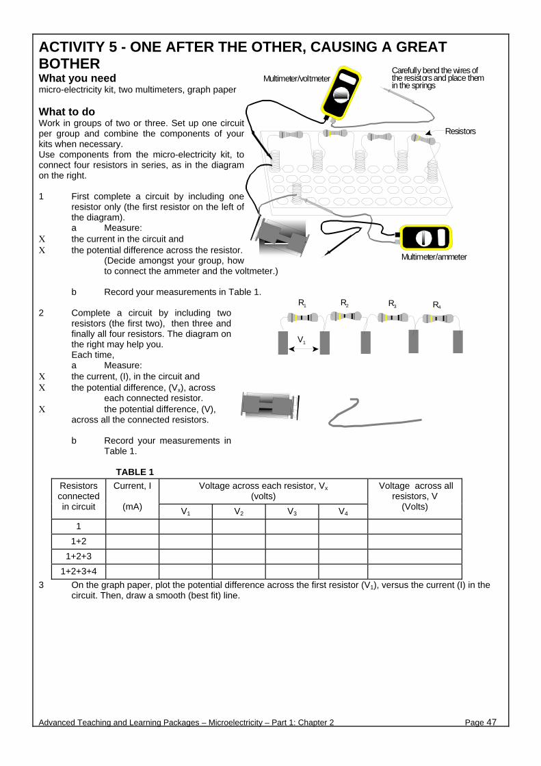
ACTIVITY 5 - ONE AFTER THE OTHER, CAUSING A GREAT BOTHER What you need micro-electricity kit, two multimeters, graph paper What to do Work in groups of two or three. Set up one circuit per group and combine the components of your kits when necessary. Use components from the micro-electricity kit, to connect four resistors in series, as in the diagram on the right.
1 First complete a circuit by including one
resistor only (the first resistor on the left of the diagram). a Measure:
Χ the current in the circuit and Χ the potential difference across the resistor.
(Decide amongst your group, how to connect the ammeter and the voltmeter.)
b Record your measurements in Table 1.
2 Complete a circuit by including two
resistors (the first two), then three and finally all four resistors. The diagram on the right may help you. Each time, a Measure:
Χ the current, (I), in the circuit and Χ the potential difference, (Vx), across
each connected resistor. Χ the potential difference, (V),
across all the connected resistors. b Record your measurements in
Table 1.
TABLE 1
Voltage across each resistor, Vx (volts)
Resistors connected in circuit
Current, I
(mA) V1 V2 V3 V4
Voltage across all resistors, V
(Volts)
1
1+2
1+2+3
1+2+3+4
3 On the graph paper, plot the potential difference across the first resistor (V1), versus the current (I) in the circuit. Then, draw a smooth (best fit) line.
Advanced Teaching and Learning Packages – Microelectricity – Part 1: Chapter 2 Page 47
Multimeter/voltmeter
Multimeter/ammeter
Carefully bend the wires ofthe resistors and place themin the springs
Resistors
R1 R4 R3 R2
V1
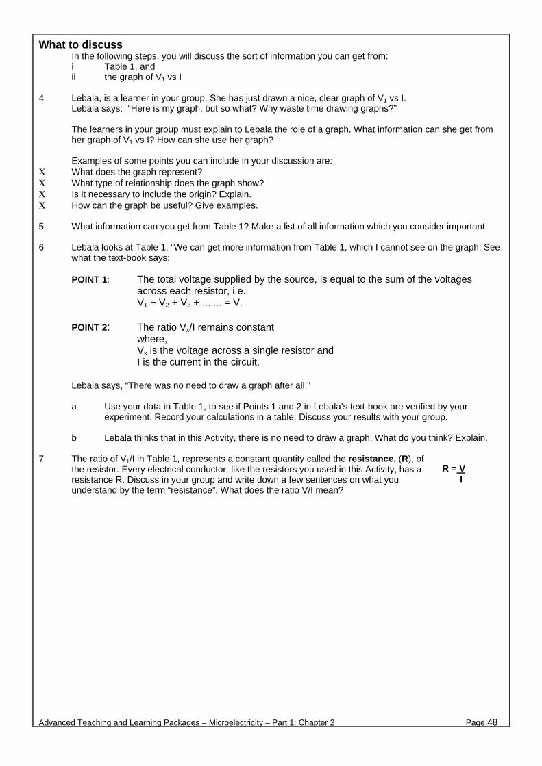
What to discuss In the following steps, you will discuss the sort of information you can get from: i Table 1, and ii the graph of V1 vs I
4 Lebala, is a learner in your group. She has just drawn a nice, clear graph of V1 vs I.
Lebala says: “Here is my graph, but so what? Why waste time drawing graphs?”
The learners in your group must explain to Lebala the role of a graph. What information can she get from her graph of V1 vs I? How can she use her graph?
Examples of some points you can include in your discussion are:
Χ What does the graph represent? Χ What type of relationship does the graph show? Χ Is it necessary to include the origin? Explain. Χ How can the graph be useful? Give examples. 5 What information can you get from Table 1? Make a list of all information which you consider important. 6 Lebala looks at Table 1. “We can get more information from Table 1, which I cannot see on the graph. See
what the text-book says:
POINT 1: The total voltage supplied by the source, is equal to the sum of the voltages across each resistor, i.e. V1 + V2 + V3 + ....... = V.
POINT 2: The ratio Vx/I remains constant
where, Vx is the voltage across a single resistor and I is the current in the circuit.
Lebala says, “There was no need to draw a graph after all!”
a Use your data in Table 1, to see if Points 1 and 2 in Lebala’s text-book are verified by your
experiment. Record your calculations in a table. Discuss your results with your group.
b Lebala thinks that in this Activity, there is no need to draw a graph. What do you think? Explain. 7 The ratio of V1/I in Table 1, represents a constant quantity called the resistance, (R), of
the resistor. Every electrical conductor, like the resistors you used in this Activity, has a resistance R. Discuss in your group and write down a few sentences on what you understand by the term “resistance”. What does the ratio V/I mean?
Advanced Teaching and Learning Packages – Microelectricity – Part 1: Chapter 2 Page 48
R = V I
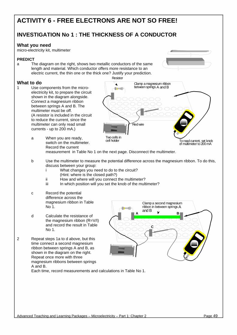
ACTIVITY 6 - FREE ELECTRONS ARE NOT SO FREE! INVESTIGATION No 1 : THE THICKNESS OF A CONDUCTOR What you need micro-electricity kit, multimeter PREDICT a The diagram on the right, shows two metallic conductors of the same
length and material. Which conductor offers more resistance to an electric current, the thin one or the thick one? Justify your prediction.
What to do 1 Use components from the micro-
electricity kit, to prepare the circuit shown in the diagram alongside. Connect a magnesium ribbon between springs A and B. The multimeter must be off. (A resistor is included in the circuit to reduce the current, since the multimeter can only read small currents - up to 200 mA.)
a When you are ready,
switch on the multimeter. Record the current measurement in Table No 1 on the next page. Disconnect the multimeter.
b Use the multimeter to measure the potential difference across the magnesium ribbon. To do this,
discuss between your group: i What changes you need to do to the circuit?
(Hint: where is the closed path?) ii How and where will you connect the multimeter? iii In which position will you set the knob of the multimeter?
c Record the potential
difference across the magnesium ribbon in Table No 1.
d Calculate the resistance of
the magnesium ribbon (R=V/I) and record the result in Table No 1.
2 Repeat steps 1a to d above, but this
time connect a second magnesium ribbon between springs A and B, as shown in the diagram on the right. Repeat once more with three magnesium ribbons between springs A and B. Each time, record measurements and calculations in Table No 1.
Advanced Teaching and Learning Packages – Microelectricity – Part 1: Chapter 2 Page 49
Red wire
Clamp a magnesium ribbonbetween springs A and B
Two cells incell holder To read current, set knob
of multimeter to 200 mA
Resistor
Clamp a second magnesiumribbon in between springs Aand B
A B
C

TABLE No 1
The Effect of the Thickness of a Conductor on its Resistance
No of magnesium ribbons
Current (mA)
P. D. across ribbon/s (V)
Resistance of ribbon/s (V/mA)
Resistance of ribbon/s
(V/A = ohms)
1
2
3
3 Joe did the same experiment, but instead of magnesium ribbons, he used the copper strips from his micro-
electricity kit. He measured the current with one, two, three copper strips on top of each other. The following table shows some of his measurements.
Number of copper strips
Current (mA) P.D. across copper strips
(V)
1 1010 0
2 1019 1
3 1014 0
Joe is worried. He cannot come to any conclusion. Luckily your group is about to help him! a Compare Joe’s current measurements with your current measurements in Table No 1. List at least
two important differences between the two sets of measurements. b Compare Joe’s and your measurements of the potential difference across the strips. What are your
comments? c Why are the connecting wires in a circuit mostly made out of copper?
4 a What happens to the resistance of a magnesium conductor when you increase its thickness?
b Do the results of this investigation confirm your prediction at the beginning of the Activity? Explain. 5 Imagine that you are a free electron in an electric circuit.
i Initially, the circuit is made up of a cell and some copper wire. ii Then, somebody connects a thin conductor in the circuit. iii After a while, the thin conductor is replaced by a thick conductor.
a Explain what changes you would experience as you move around the circuit, in each case. b In a few sentences, prepare a group report to explain the effect of the thickness of a conductor on
its resistance.
Advanced Teaching and Learning Packages – Microelectricity – Part 1: Chapter 2 Page 50
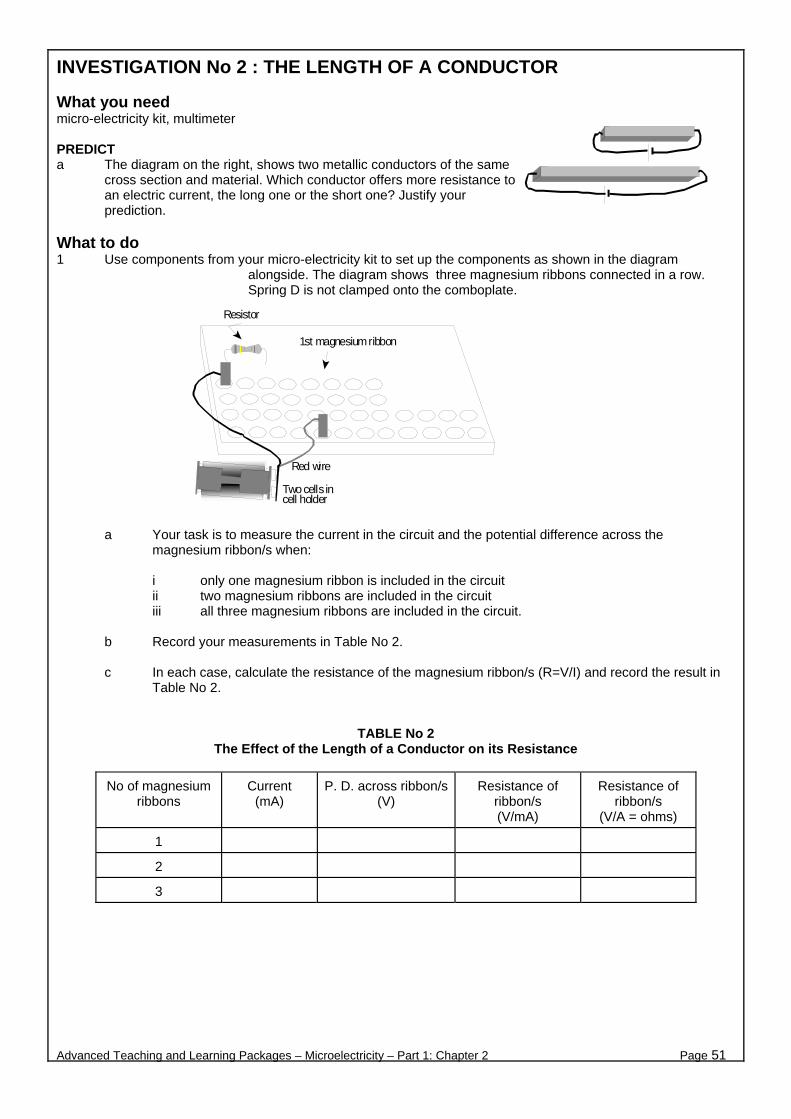
INVESTIGATION No 2 : THE LENGTH OF A CONDUCTOR What you need micro-electricity kit, multimeter PREDICT a The diagram on the right, shows two metallic conductors of the same
cross section and material. Which conductor offers more resistance to an electric current, the long one or the short one? Justify your prediction.
What to do 1 Use components from your micro-electricity kit to set up the components as shown in the diagram
alongside. The diagram shows three magnesium ribbons connected in a row. Spring D is not clamped onto the comboplate.
a Your task is to measure the current in the circuit and the potential difference across the magnesium ribbon/s when:
i only one magnesium ribbon is included in the circuit ii two magnesium ribbons are included in the circuit iii all three magnesium ribbons are included in the circuit.
b Record your measurements in Table No 2. c In each case, calculate the resistance of the magnesium ribbon/s (R=V/I) and record the result in
Table No 2.
TABLE No 2 The Effect of the Length of a Conductor on its Resistance
No of magnesium ribbons
Current (mA)
P. D. across ribbon/s (V)
Resistance of ribbon/s (V/mA)
Resistance of ribbon/s
(V/A = ohms)
1
2
3
Advanced Teaching and Learning Packages – Microelectricity – Part 1: Chapter 2 Page 51
Red wire
1st magnesium ribbon
Two cells incell holder
Resistor

What to discuss 2 a What happens to the resistance of a magnesium conductor when you increase its length?
b Do the results of this investigation confirm your prediction at the beginning of the Activity? Explain.
c In a few sentences, prepare a group report to explain the effect of the length of a conductor on its resistance.
3 What would you expect to observe in this investigation, if instead of magnesium ribbons you used the
copper strips from the kit?
Advanced Teaching and Learning Packages – Microelectricity – Part 1: Chapter 2 Page 52

INVESTIGATION No 3 : THE MATERIAL OF A CONDUCTOR What you need micro-electricity kit, multimeter PREDICT a The connecting wires of electric circuits are usually made out of copper wire. However, copper is a fairly
expensive metal. Why don’t we use zinc wires which would be more cheaper? b In this investigation, you will use roughly similar strips made out of magnesium, copper and zinc. Predict
which strip will have the greatest resistance, and list the three materials in order of increasing resistance. Justify your answer.
What to do 1 Use your micro-
electricity kit to set up the components as shown in the diagram alongside.
Connect each of the three metallic strips (one at a time) between springs A and B.
a For each strip, measure the current in the circuit and the potential difference across the strip. b Record your measurements in Table No 3 on the next page. c In each case, calculate the resistance of the strip (R=V/I) and record the result in Table No 3.
2 Now that you are experts in measuring resistance, why not measure the resistance of some more devices
from your micro-electricity kit (bulb, LED, resistors). In this case, bring the springs A and B closer, as in the following diagram.
a For each device, measure the current in the circuit and the potential difference across the device. b Record your measurements in Table No 3. c In each case, calculate the resistance of the device (R=V/I). Record the result in Table No 3.
Advanced Teaching and Learning Packages – Microelectricity – Part 1: Chapter 2 Page 53
Red wire
Clamp the metallic strips one at a timebetween springs A and B
Two cells incell holder
To read current, set knobof multimeter at 200 mA
Resistor
Red wire
Two cells incell holder
To read current, set knobof multimeter at 200 mA
Resistor
Multimeter
A B
CResistor 2
LED
Resistor 1
Light bulb inbulb holder
When connecting the LED,move the springs A and Bnext to each other A B
Golden stripe
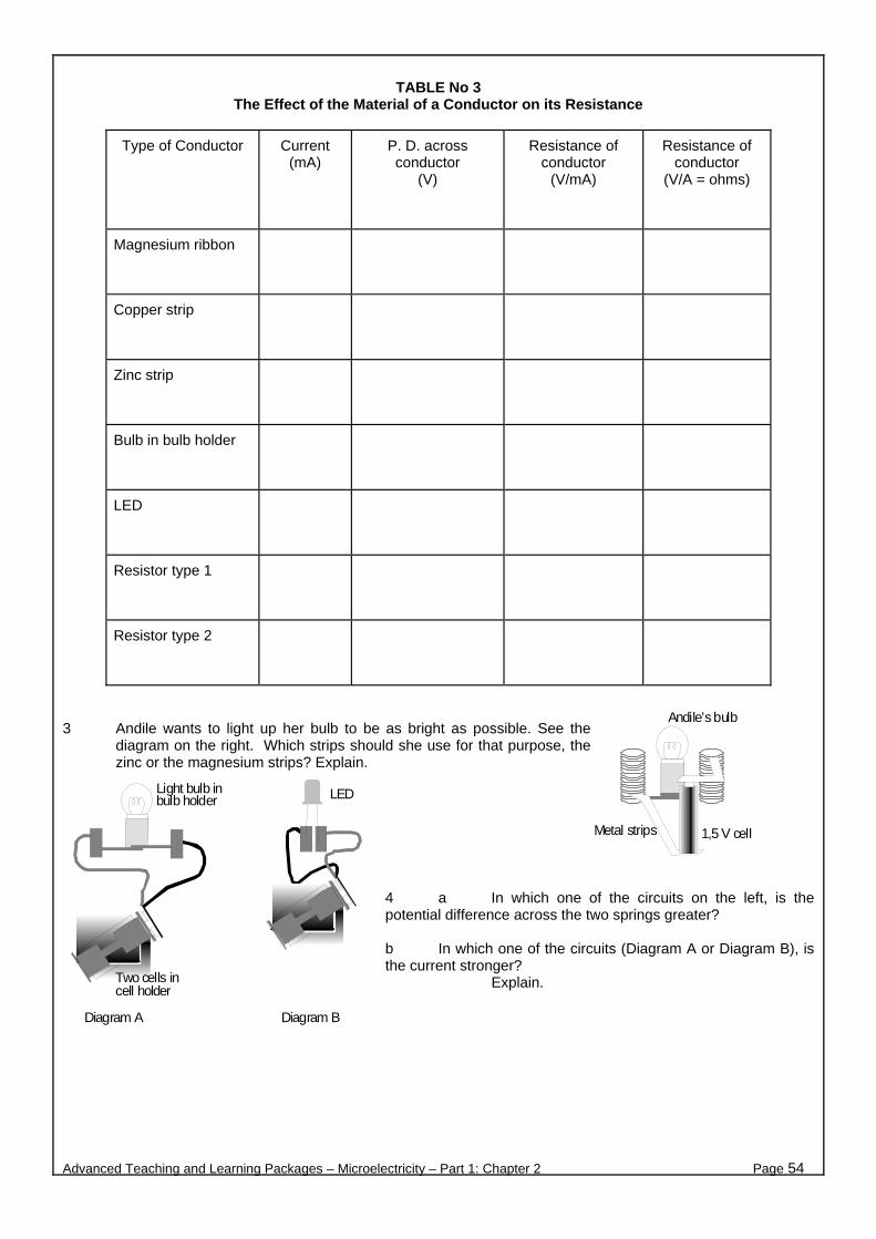
TABLE No 3
The Effect of the Material of a Conductor on its Resistance
Type of Conductor Current (mA)
P. D. across conductor
(V)
Resistance of conductor
(V/mA)
Resistance of conductor
(V/A = ohms)
Magnesium ribbon
Copper strip
Zinc strip
Bulb in bulb holder
LED
Resistor type 1
Resistor type 2
3 Andile wants to light up her bulb to be as bright as possible. See the
diagram on the right. Which strips should she use for that purpose, the zinc or the magnesium strips? Explain.
4 a In which one of the circuits on the left, is the potential difference across the two springs greater? b In which one of the circuits (Diagram A or Diagram B), is the current stronger? Explain.
Advanced Teaching and Learning Packages – Microelectricity – Part 1: Chapter 2 Page 54
Andile’s bulb
1,5 V cellMetal strips
LED
Two cells incell holder
Light bulb inbulb holder
Diagram A Diagram B

INVESTIGATION No 4 : THE TEMPERATURE OF A CONDUCTOR What you need micro-electricity kit, multimeter, hot water, a plastic lid from a coffee jar or similar dish, cold water or ice-blocks (optional) PREDICT a What happens to the particles of a material when its temperature rises? b Predict which metallic conductor offers more resistance to the flow of electric charge,
i) a conductor at 20 oC or ii) a conductor at 80 oC. Justify your answer.
In this investigation, you will calculate and compare the resistance of a conductor at two different temperatures. What to do 1 Use your micro-electricity kit to set
up the components as shown in the diagram on the right.
a Measure the current in the
circuit and the potential difference across the magnesium strips. Record your measurements in the Table No 4 on the following page.
Tc
b Calculate the resistance of the strips (R=V/I) and record the result in Table 4.
2 Fill the lid or shallow dish with hot water.
Immerse the magnesium ribbons in the hot water, see the following diagram.
While the ribbons are in the hot water, repeat steps 1a and 1b above.
Repeat this step with cold water if available.
Advanced Teaching and Learning Packages – Microelectricity – Part 1: Chapter 2 Page 55
Red wire
Clamp two magnesium ribbonstogether between two springs.
wo cells inell holder
Resistor
Multimeter
Connect springs C and Bwith a copper strip tocomplete the circuit whennecessary.
Dip the magnesiumribbons in the hotwater.
A B
C
Hot water

TABLE No 4
The Effect of the Temperature of a Conductor on its Resistance
Current (mA)
P. D. across ribbons
(V)
Resistance of ribbon/s (V/mA)
Resistance of ribbon/s
(V/A = ohms)
Conductor in cold water
Conductor at room temperature
Conductor in hot water
3 a Compare your results with your prediction. What happens to the resistance of the magnesium
ribbon as the temperature rises? b What do you expect to happen to the resistance of a material, if its temperature keeps on
dropping? Discuss between your group things like: Is it possible for the resistance of a material to become exactly zero? At which temperature would that be? Is there a minimum temperature in nature? Have you ever heard of superconducting materials, if so what?
Advanced Teaching and Learning Packages – Microelectricity – Part 1: Chapter 2 Page 56
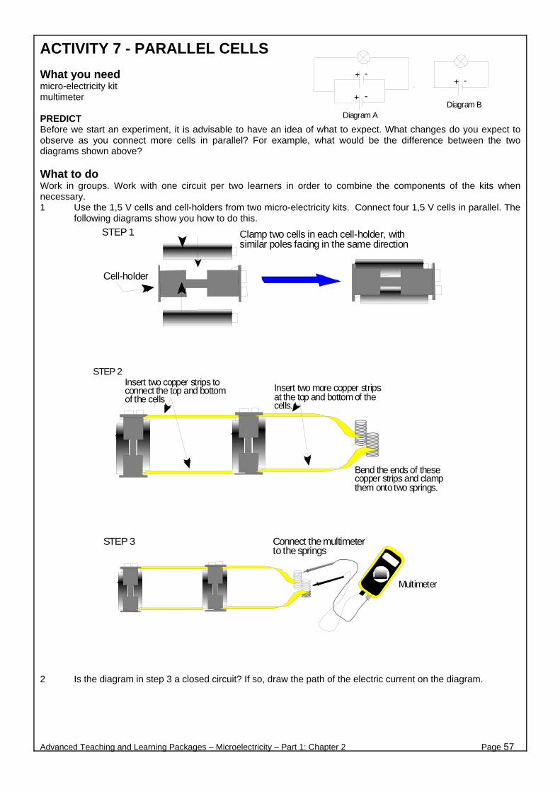
ACTIVITY 7 - PARALLEL CELLS What you need micro-electricity kit multimeter PREDICT Before we start an experiment, it is advisable to have an idea of what to expect. What changes do you expect to observe as you connect more cells in parallel? For example, what would be the difference between the two diagrams shown above? What to do Work in groups. Work with one circuit per two learners in order to combine the components of the kits when necessary. 1 Use the 1,5 V cells and cell-holders from two micro-electricity kits. Connect four 1,5 V cells in parallel. The
following diagrams show you how to do this.
2 Is the diagram in step 3 a closed circuit? If so, draw the path of the electric current on the diagram.
Advanced Teaching and Learning Packages – Microelectricity – Part 1: Chapter 2 Page 57
+ -
+ -
Diagram A
+ -
Diagram B
Clamp two cells in each cell-holder, withsimilar poles facing in the same direction
Cell-holder
STEP 1
Insert two copper strips toconnect the top and bottomof the cells
STEP 2
Insert two more copper stripsat the top and bottom of thecells.
Bend the ends of thesecopper strips and clampthem onto two springs.
STEP 3
Multimeter
Connect the multimeterto the springs
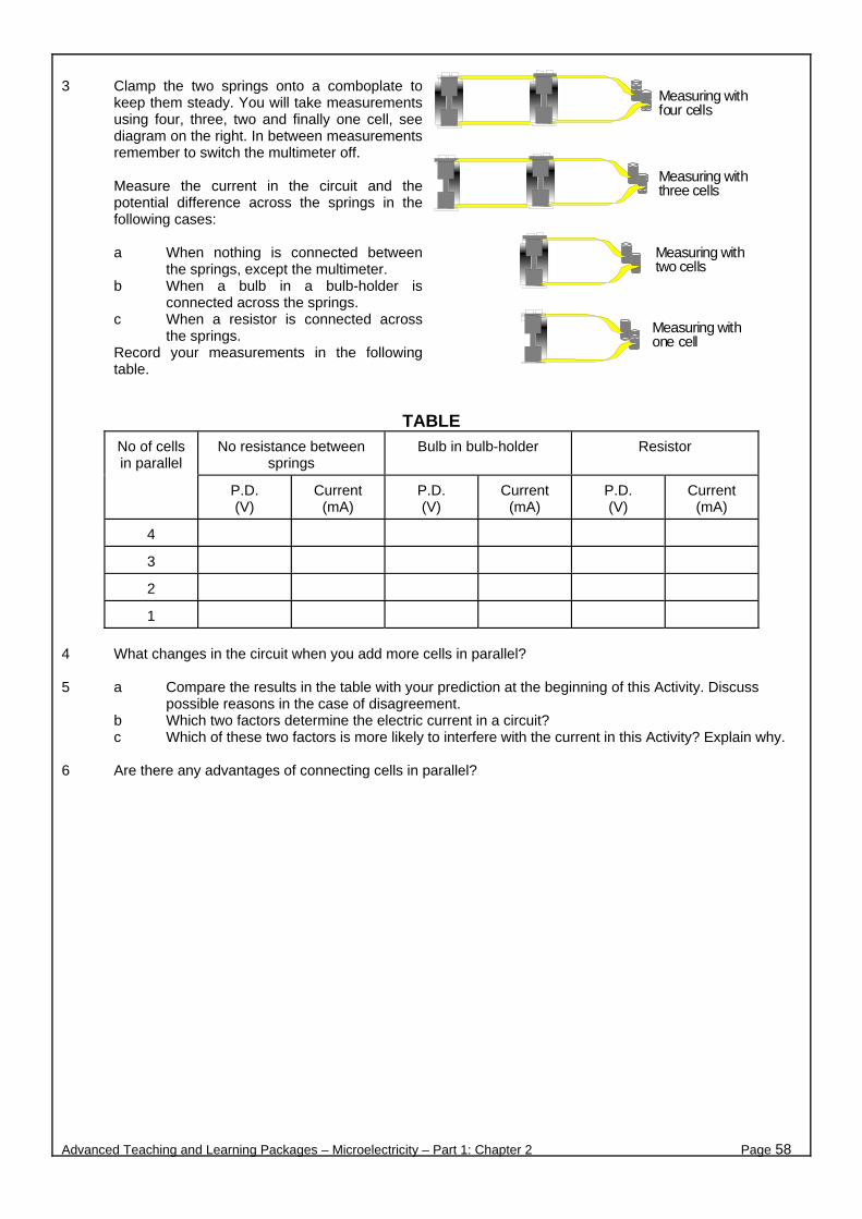
3 Clamp the two springs onto a comboplate to
keep them steady. You will take measurements using four, three, two and finally one cell, see diagram on the right. In between measurements remember to switch the multimeter off.
Measure the current in the circuit and the potential difference across the springs in the following cases:
a When nothing is connected between
the springs, except the multimeter. b When a bulb in a bulb-holder is
connected across the springs. c When a resistor is connected across
the springs. Record your measurements in the following table.
TABLE
No resistance between springs
Bulb in bulb-holder Resistor
No of cells in parallel
P.D. (V)
Current (mA)
P.D. (V)
Current (mA)
P.D. (V)
Current (mA)
4
3
2
1
4 What changes in the circuit when you add more cells in parallel? 5 a Compare the results in the table with your prediction at the beginning of this Activity. Discuss
possible reasons in the case of disagreement. b Which two factors determine the electric current in a circuit? c Which of these two factors is more likely to interfere with the current in this Activity? Explain why.
6 Are there any advantages of connecting cells in parallel?
Advanced Teaching and Learning Packages – Microelectricity – Part 1: Chapter 2 Page 58
Measuring withfour cells
Measuring withthree cells
Measuring withtwo cells
Measuring withone cell

ACTIVITY 8 - FIRST CONTACT WITH THE LOOPS What you Need micro-electricity kit, multimeter YOUR MULTIMETER AS A VOLTMETER 1 The diagram on the right roughly shows what your
multimeter looks like. The multimeter becomes a voltmeter, when the pointer points at any of the dots shown on the left hand side of the multimeter, as shown in the diagram. a What is the voltage provided by the power sources
of your micro-electricity kit? b Which dot in the diagram is nearest in value to these
kinds of voltages? 2 You want to know the potential difference across the bulb in the diagram on the left. How do you connect a
voltmeter? a Do you connect the voltmeter in the same loop with the bulb, so that the current can pass through the voltmeter? b Do you need to make a new loop? Will this cause the current in the circuit to branch (some current through the voltmeter)? c How do we deal with these two points? Remember a meter connected in a circuit must not interfere with the circuit.
d Which diagram on the right represents the correct connection of the voltmeter?
3 The following diagram shows two circuits made with components from the micro-electricity kit.
a Draw a circuit diagram for each of the circuits 1 and 2. b Discuss the role of the multimeter in each circuit.
Is it used as an ammeter or as a voltmeter? Explain.
c Discuss in your group, whether these circuits are series or parallel circuits. Explain.
d How many loops are there in each circuit? Hint: There is no loop without a power source!
e How many loops do you see in the diagram alongside? Indicate the loops in the diagram.
Advanced Teaching and Learning Packages – Microelectricity – Part 1: Chapter 2 Page 59
2000 m
200m
When the pointer is atany of these dots, themultimeter is avoltmeter
...V 20
200500
V
Bulb
Cell
I
VV
Diagram (a) Diagram (b)
V
Copper or zinc stripsinserted in the springsCircuit 2
Copper or zinc stripsinserted in springs
Bulb 3
Bulb 4
Bulb 1 Bulb 2

TO INVESTIGATE 4 Use components from your micro-electricity
kit to set up the circuit shown in the diagram alongside. Use a single 1,5 V cell.
a Investigate what happens to the total
current in the circuit, when you add more bulbs in parallel. (Take your measurements quickly!!! Remember to switch off the multimeter between measurements.) Take measurements of one, two and then three bulbs in parallel. Prepare a table to record your measurements and observations.
b Measure the potential difference across each bulb when three bulbs are connected in parallel.
Record measurements and observations.
When you finish your measurements, do not disconnect the three bulbs. 5 Replace the single cell with two cells in the cell holder. All bulbs should glow.
a Remove one bulb (or just unscrew it) from the circuit. What happens to the other bulbs?
b Repeat with the other bulbs. What happens? Explain why. 6 The diagram on the right shows a circuit with three identical bulbs and three
switches S1, S2 and S3 connected as shown.
a If switches S1, S2 are closed and S3 is open, which bulbs will glow? b If switches S1, S2 are open and S3 is closed, which bulbs will glow? c If switches S3 and S1 are closed and S2 is open, which bulbs will
glow? d In this circuit, is it possible to have only bulb 2 glowing? Explain.
7 List what have you discovered in this Activity, about:
a The current in a parallel circuit. b The potential difference across components in a parallel circuit.
COMPARE SERIES AND PARALLEL CIRCUITS 8 a What happens when you remove one bulb/component
i from a series circuit? ii from a parallel circuit? Explain.
b What happens to the current in a circuit, as you connect more bulbs/components
i in series? ii in parallel? Explain.
Advanced Teaching and Learning Packages – Microelectricity – Part 1: Chapter 2 Page 60
Clamp a copper strip to connect the twocontacts in one compartment of the cellholder.Insert a 1,5 V cell in the other compartmentof the cell holder.
Two 1,5 V cells inthe cell-holder
S1
CHAPTER 3
Advanced Teaching and Learning Packages – Microelectricity – Part 1: Chapter 3 Page 61
A. THE ELECTRIC CURRENT

ACTIVITY 1 - THE MODELLING BUSINESS In science we often use models, because we often deal with things which we cannot see or are difficult to describe and understand. For example, an atom is too small to see. When we want to visualise an atom, we use the planetary model. We say that the Sun represents the nucleus and the planets represent the electrons. The electrons orbit around the nucleus just as the planets orbit around the Sun. The electrons spin around themselves just as planets spin around themselves. The planetary model of the atom is useful to understand basic aspects of the atom. But the atom is not a planetary system, nor does it look like one. We can only use the planetary model as far as it can take us.
This is the case with all models. They can help us only up to a point. They are limited. We then have to drop them, or change them or look for other models. Remember, models can be very useful as long as we remember that they are not the real thing, otherwise, they can also be very misleading! In this Activity, you will discuss models that show analogies of the electric current and the various components in a simple circuit. You will identify analogies with an electric circuit and you will discuss the models’ advantages and limitations. What you need A bicycle - for the bicycle chain model a long piece of string (about 5 to 6 metres long) and two chairs - for the taut string model What to do THE MOST FAMOUS MODEL 1 Discuss between your group and write down at least three differences between an atom and our planetary
system (other than the size!) THE ELECTRIC CURRENT - OLD FAVOURITES 2 Read quickly through the four models below. Choose one of the models and discuss it thoroughly in your
group. MODEL A - THE WATER FLOW: A pump circulates water around the water-pipe. A paddlewheel works when the pump is working. The tap stops the movement of the water.
MODEL B - THE BICYCLE CHAIN: The cyclist turns the pedal. The chain moves. The wheel turns. If you choose this model, put the
bicycle upside-down on the desk and turn a pedal with your hand.
Advanced Teaching and Learning Packages – Microelectricity – Part 1: Chapter 3 Page 62
TapPump
Paddle-wheel
chain
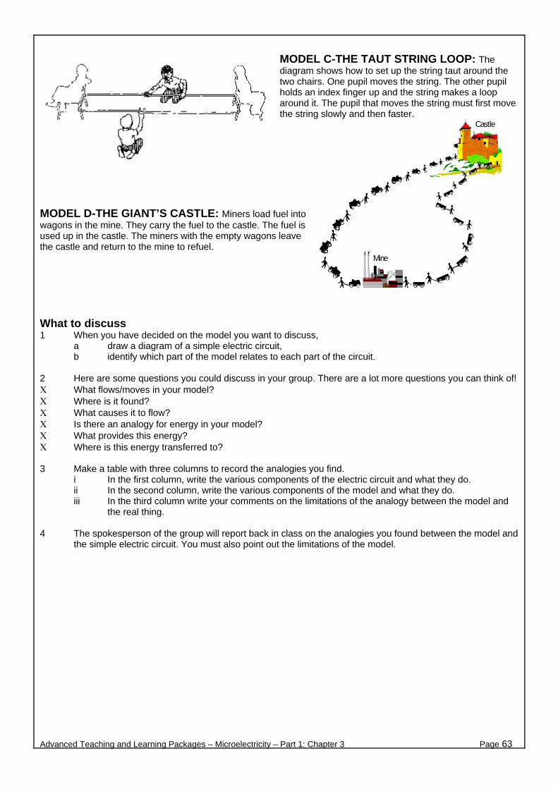
MODEL C-THE TAUT STRING LOOP: The diagram shows how to set up the string taut around the two chairs. One pupil moves the string. The other pupil holds an index finger up and the string makes a loop around it. The pupil that moves the string must first move the string slowly and then faster.
MODEL D-THE GIANT’S CASTLE: Miners load fuel into wagons in the mine. They carry the fuel to the castle. The fuel is used up in the castle. The miners with the empty wagons leave the castle and return to the mine to refuel. What to discuss 1 When you have decided on the model you want to discuss,
a draw a diagram of a simple electric circuit, b identify which part of the model relates to each part of the circuit.
2 Here are some questions you could discuss in your group. There are a lot more questions you can think of! Χ What flows/moves in your model? Χ Where is it found? Χ What causes it to flow? Χ Is there an analogy for energy in your model? Χ What provides this energy? Χ Where is this energy transferred to? 3 Make a table with three columns to record the analogies you find.
i In the first column, write the various components of the electric circuit and what they do. ii In the second column, write the various components of the model and what they do. iii In the third column write your comments on the limitations of the analogy between the model and
the real thing. 4 The spokesperson of the group will report back in class on the analogies you found between the model and
the simple electric circuit. You must also point out the limitations of the model.
Advanced Teaching and Learning Packages – Microelectricity – Part 1: Chapter 3 Page 63
Castle
Mine

ACTIVITY 2 - WHAT GOES UP MUST FALL DOWN Why do charges in wires not flow unless the wires are connected to a battery? For the same reason why when we throw a stone out of a window it falls downwards towards the ground! It is a matter of difference in potential energy. DIFFERENCES IN HEIGHT
Alex is a primary school boy, who is often up to mischief. This morning, he dropped a stone out of a third floor window. The roof of his mother’s car now has a great dent in it! “Mom, it was a small stone!” Alex said. “Yes, but a small stone from a big height causes lots of damage, it has lots of energy!”
Consider a stone of mass m on the ground. The stone has no potential energy in respect to the ground. You lift the stone from the ground up to a height h. To overcome the force of gravity you exert an upward force on the stone. That is, you do work on the stone, you transfer energy to the stone (remember, when you do work you transfer energy). The stone now has gravitational potential energy in respect to the ground. You know this because if you let the stone free, something happens. The stone starts moving - it falls, and when it hits the ground it can cause damage. DIFFERENCES IN ELECTRIC POTENTIAL Much the same way, if you want to move an electric charge from one point to another, you must apply a potential difference between these two points. This is what a power source does. In an electric circuit, we consider the movement of the positive charge, the conventional current. Consider the simple circuit shown in the diagram. For simplicity, we assume that cells, springs and connecting wires have no resistance. In the diagram, spring A is connected to the positive terminal, and spring B is connected to the negative terminal of the cells. The positive terminal is at high potential (3 V), the negative terminal is at low potential (0 V). The difference in potential between the positive and negative terminals is 3 V. Therefore, the difference in potential between points A and B (across the bulb) is also 3 V. Positive charge that moves from A to B, “falls” from 3 to 0 volts, i.e. moves from a higher to a lower potential. The charge loses its potential energy! This lost potential energy transfers to the bulb (so it’s not really lost!) And the bulb glows! A charge of one coulomb, can transfer one joule of energy to a device, for each volt of potential difference across the device. In the case of the diagram above, the potential difference across the device (the bulb) is 3 V, therefore, one coulomb of charge transfers 3 joules of energy to the bulb. We can say the same thing in different words: There is a potential difference of 3 V across the bulb, if each coulomb of charge loses 3 joules of electrical potential energy as it passes through the bulb. And because there are more ways to say the same thing, we use an equation to summarise it all!
Potential difference = Energy transferred / Charge
Advanced Teaching and Learning Packages – Microelectricity – Part 1: Chapter 3 Page 64
Two 1,5 V cells inthe cell-ho lder
A B
A B
VAB=3V
+ −
V= W Q

What you need Micro-electricity kit, two 2 litre plastic bottles, tap water, flexible pipe/tubing, about 1 m long, like a hose pipe. A silicon pipe would be the best, as it is transparent
THE SIPHON Alex loves his goldfish. He wants to clean the dirt from the gravel in their fish-tank. He decides to siphon the dirt out. Alex brings a bucket and a long flexible pipe, as he saw in a book. He puts one end of the pipe in the tank, the other end inside the bucket. He waits.... nothing happens. The bucket is still empty and the dirt still in the gravel!!!
What to do 1 Help Alex to clean the fish-tank. Show him what to do.
Use a flexible pipe and the two 2 litre plastic bottles to represent the fish-tank and bucket. See if you can get water flowing between the two bottles through the pipe. Record all observations. Under which conditions will water flow inside the pipe? In which direction? How can you make the water flow faster or slower? How would you explain to Alex in scientific terms, what is happening? Prepare to report back your conclusions.
THE CHARGE AND ITS FLOW 2 The diagram on the right, shows a bulb and a cell connected in four different ways. a In each case, predict if the bulb glows or not and why. Explain in terms of potential energy. b Use components from your micro-electricity kit to test your predictions. c Use your equipment to increase the flow of charge through the bulb. Explain in terms of energy, how this change affects the performance of the bulb. FIND THE ANALOGIES 3 In the diagram on the left, draw a line to connect each circuit diagram to the corresponding water flow diagram. In each case, give reasons why you think there is an analogy between each pair of diagrams.
COMPARE 4 There are many similarities in the way masses with gravitational potential energy, and electric charges with
electrical potential energy behave.
Use what you have discovered in this Activity, and what you already know, to compare masses falling in a gravitational field with charges “falling” in an electric field.
Think of analogies, similarities, and differences. You may use examples, like what you did with the bottles, or consider a falling stone, and compare it with the movement of charge in a simple electric circuit. Discuss between your group and record your conclusions in a table.
Advanced Teaching and Learning Packages – Microelectricity – Part 1: Chapter 3 Page 65
+
−
+
−
+
−
+
−
A
B
A B
B
BA
A
B
+
−
+
−
+
−
+
−+
−
BAFlexiblepipe
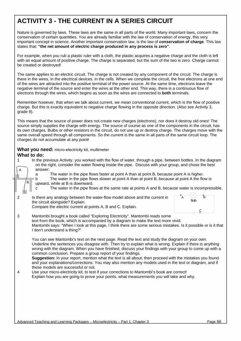
ACTIVITY 3 - THE CURRENT IN A SERIES CIRCUIT Nature is governed by laws. These laws are the same in all parts of the world. Many important laws, concern the conservation of certain quantities. You are already familiar with the law of conservation of energy, this very important concept in science. Another important conservation law, is the law of conservation of charge. This law states that: “the net amount of electric charge produced in any process is zero”. For example, when you rub a plastic ruler with a cloth, the plastic acquires a negative charge and the cloth is left with an equal amount of positive charge. The charge is separated, but the sum of the two is zero. Charge cannot be created or destroyed! The same applies to an electric circuit. The charge is not created by any component of the circuit. The charge is there in the wires, in the electrical devices, in the cells. When we complete the circuit, the free electrons at one end of the wires are attracted into the positive terminal of the power source. At the same time, electrons leave the negative terminal of the source and enter the wires at the other end. This way, there is a continuous flow of electrons through the wires, which begins as soon as the wires are connected to both terminals. Remember however, that when we talk about current, we mean conventional current, which is the flow of positive charge. But this is exactly equivalent to negative charge flowing in the opposite direction. (Also see Activity 3, grade 9). This means that the source of power does not create new charges (electrons), nor does it destroy old ones! The source simply supplies the charge with energy. The source of course as one of the components in the circuit, has its own charges. Bulbs or other resistors in the circuit, do not use up or destroy charge. The charges move with the same overall speed through all components. So the current is the same in all parts of the same circuit loop. The charges do not accumulate at any point! What you need: micro-electricity kit, multimeter What to do: 1 In the previous Activity, you worked with the flow of water, through a pipe, between bottles. In the diagram
on the right, consider the water flowing inside the pipe. Discuss with your group, and chose the best answer: a The water in the pipe flows faster at point A than at point B, because point A is higher. b The water in the pipe flows slower at point A than at point B, because at point A the flow is upward, while at B is downward. c The water in the pipe flows at the same rate at points A and B, because water is incompressible.
2 Is there any analogy between the water-flow model above and the current in the circuit alongside? Explain. Compare the electric current at points A, B and C. Explain.
3 Mantombi brought a book called “Exploring Electricity”. Mantombi reads some
text from the book, which is accompanied by a diagram to make the text more vivid. Mantombi says: “When I look at this page, I think there are some serious mistakes. Is it possible or is it that
I don’t understand a thing?”
You can see Mantombi’s text on the next page. Read the text and study the diagram on your own. Underline the sentences you disagree with. Then try to explain what is wrong. Explain if there is anything wrong with the diagram. When you have finished, discuss your findings with your group to come up with a common conclusion. Prepare a group report of your findings. Suggestion: In your report, mention what the text is all about, then proceed with the mistakes you found and your explanations/corrections. You may also mention any models used in the text or diagram, and if these models are successful or not.
4 Use your micro-electricity kit, to test if your corrections to Mantombi’s book are correct! Explain how you are going to prove your points, what measurements you will take and why.
Advanced Teaching and Learning Packages – Microelectricity – Part 1: Chapter 3 Page 66
A
B
BulbBA
C

THIS IS THE TEXT & DIAGRAM FROM MANTOMBI’S BOOK
Advanced Teaching and Learning Packages – Microelectricity – Part 1: Chapter 3 Page 67

ACTIVITY 4 - THE REAL & THE IDEAL WORLD In science we often simplify the way we see the world. This is a valuable technique but it is not so easy! We try to imagine what would happen in idealised cases. Galileo was the first to introduce this technique, when he analysed the laws governing the “falling bodies”. He ignored the air. He imagined that objects fall in a vacuum. He came to the conclusion that all falling objects dropped from the same height, land at the same time. But when we drop a marble and a feather from the same height, we see the marble landing first far ahead of the feather! This is the real world with air and friction!!! Look at the circuit diagram alongside. When we study what type of relationship exists between the current in the circuit and the potential difference across a resistor, we make all sorts of assumptions. We assume that all connecting wires have no resistance. We assume that the source of power has no resistance. We assume that the voltmeter and ammeter do not interfere with the circuit, as if they were not there. But all these happen in an ideal world, the world of simplification (and abstraction)! In electricity, the equipment we use is real. And connecting wires, meters, cells, .... they all interfere with the current in our circuit. The result? It reflects in our measurements! What sort of discrepancies can we expect between reality and theory? Let us take a look in this Activity. What you need micro-electricity kit, two multimeters What to do REFRESH UP YOUR MEMORY 1 We say (and we want) that meters for measuring
current and voltage, must not interfere with our circuit. a Comment on the resistance of a good
ammeter. b Comment on the resistance of a good
voltmeter. TEST YOUR AMMETER 2 In diagram 1, the ammeter reads 45 mA.
a How will you know if this is the correct reading of the current in the circuit? What can you do to test if the ammeter changes the current in the circuit?
b If you connect a second ammeter in the same circuit, what do you expect both ammeters to read?
c Try it with your equipment. What do both
ammeters actually read? What does this tell you?
TEST YOUR VOLTMETER 3 In diagram 2, the voltmeter reads 2,85 V across
the springs A and B. a What do you expect the voltmeter to read
across the springs A and C?
b Try this with your equipment. What does it read? What does this tell you about your voltmeter?
TEST YOUR CELLS 4 In the figure below, the voltmeter reads 2,80 V when nothing is connected between springs A and B.
a What should the voltmeter read when an LED is connected between springs A and B?
b Try this with your equipment. What does the voltmeter read? What does this tell you about the resistance and the current in your circuit?
Advanced Teaching and Learning Packages – Microelectricity – Part 1: Chapter 3 Page 68
A
V
LED
The ammeter reads 45 mA.
Diagram 1
LED
Voltmeter
B
A
C
Diagram 2
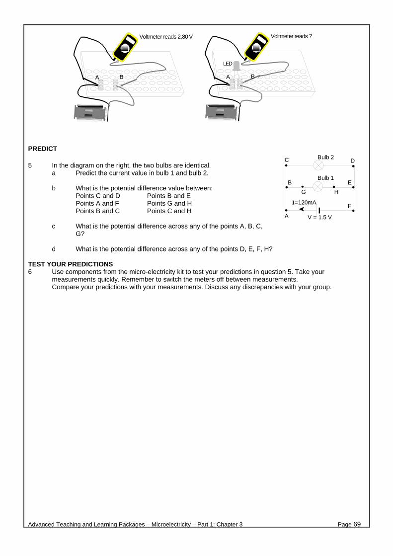
PREDICT 5 In the diagram on the right, the two bulbs are identical.
a Predict the current value in bulb 1 and bulb 2.
b What is the potential difference value between: Points C and D Points B and E Points A and F Points G and H Points B and C Points C and H
c What is the potential difference across any of the points A, B, C,
G?
d What is the potential difference across any of the points D, E, F, H? TEST YOUR PREDICTIONS 6 Use components from the micro-electricity kit to test your predictions in question 5. Take your
measurements quickly. Remember to switch the meters off between measurements. Compare your predictions with your measurements. Discuss any discrepancies with your group.
Advanced Teaching and Learning Packages – Microelectricity – Part 1: Chapter 3 Page 69
Voltmeter reads 2,80 V
BA
Voltmeter reads ?
BA
LED
I=120mA
Bulb 1
V = 1.5 V
B E
C
A
D
F
G H
Bulb 2
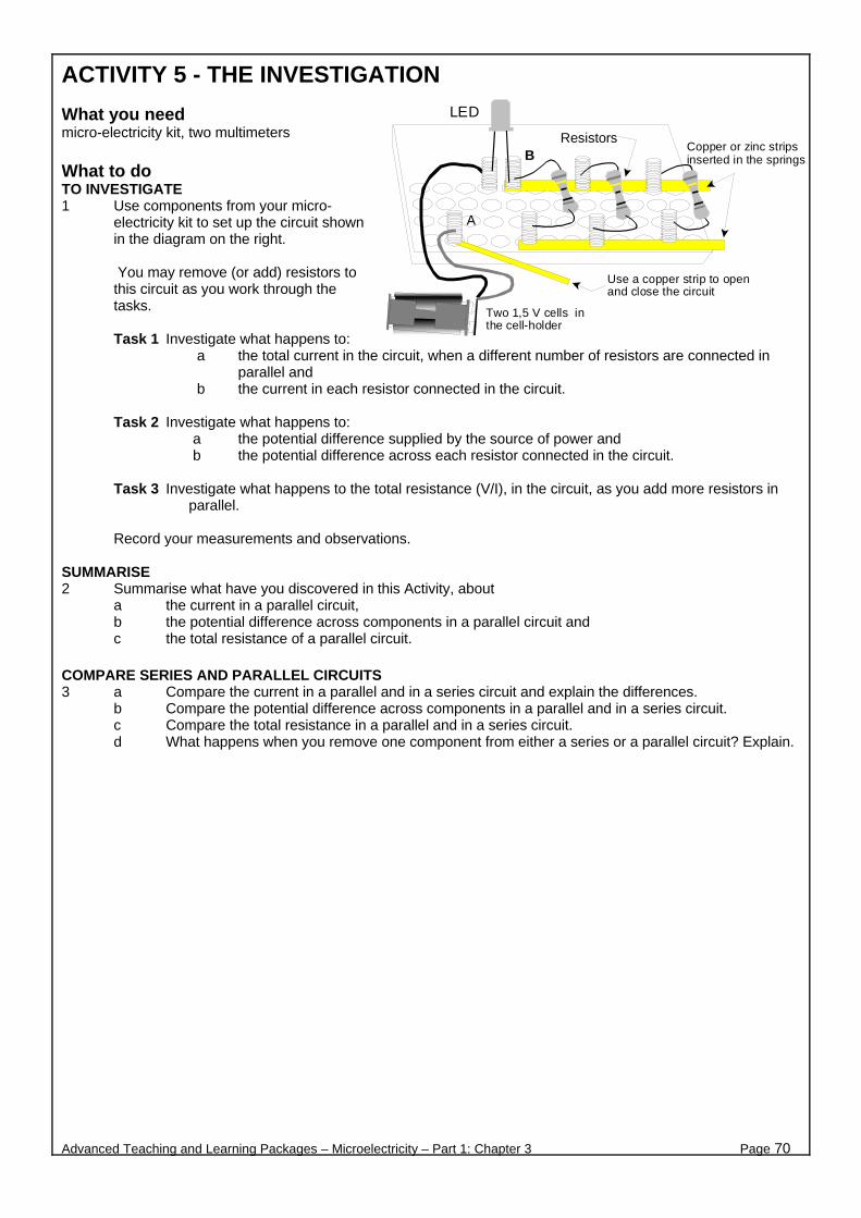
ACTIVITY 5 - THE INVESTIGATION What you need micro-electricity kit, two multimeters What to do TO INVESTIGATE 1 Use components from your micro-
electricity kit to set up the circuit shown in the diagram on the right.
You may remove (or add) resistors to this circuit as you work through the tasks.
Task 1 Investigate what happens to:
a the total current in the circuit, when a different number of resistors are connected in parallel and
b the current in each resistor connected in the circuit.
Task 2 Investigate what happens to: a the potential difference supplied by the source of power and b the potential difference across each resistor connected in the circuit.
Task 3 Investigate what happens to the total resistance (V/I), in the circuit, as you add more resistors in
parallel.
Record your measurements and observations. SUMMARISE 2 Summarise what have you discovered in this Activity, about
a the current in a parallel circuit, b the potential difference across components in a parallel circuit and c the total resistance of a parallel circuit.
COMPARE SERIES AND PARALLEL CIRCUITS 3 a Compare the current in a parallel and in a series circuit and explain the differences.
b Compare the potential difference across components in a parallel and in a series circuit. c Compare the total resistance in a parallel and in a series circuit. d What happens when you remove one component from either a series or a parallel circuit? Explain.
Advanced Teaching and Learning Packages – Microelectricity – Part 1: Chapter 3 Page 70
Copper or zinc stripsinserted in the springs
Two 1,5 V cells inthe cell-holder
LED
Resistors
Use a copper strip to openand close the circuit
A
B
B. ELECTROMAGNETISM & ELECTROMAGNETIC
INDUCTION
Advanced Teaching and Learning Packages – Microelectricity – Part 1: Chapter 3 Page 71

ACTIVITY 1 - FANCY EFFECTS In the recent centuries, electricity and magnetism were considered as two unrelated phenomena. During the 18th century, many natural philosophers tried to find a connection between electricity and magnetism. In 1820, Hans Christian Oersted uncovered a significant connection: A magnetic compass needle near an electric wire would deflect (move)! What you need micro-electricity kit OERSTED’S AND YOUR INVESTIGATION 1 What conclusion did Oersted draw from his observation?
Magnetic compass 2 The diagram above right shows a simple electric circuit.
a Work on your own. Which of the following do you expect to observe when the switch is closed? Write your predictions in the table below.
(i) A compass needle placed on either side of any of the wires will deflect. (ii) A compass needle will deflect if placed on top of the bulb. (iii) A compass needle will deflect near the wires but not near the cells or bulb. (iv) A compass needle will deflect at any location near the circuit. (v) A compass needle will deflect in opposite directions if placed on top or beneath the same wire. (vi) Other, explain.
b Discuss your predictions with the other members of your group. Come up with a group prediction,
and complete the table below. TABLE
Your prediction Group’s prediction Observation Comments
i
ii
iii
iv
v
vi
c Test your predictions using the micro-electricity equipment. Complete the table above.
Discuss with your group, and come up with a conclusion. 3 a In which positions does a compass needle deflect the most if placed at different locations near the
components of an electric circuit?
b What type of effect have you discovered in this investigation?
Advanced Teaching and Learning Packages – Microelectricity – Part 1: Chapter 3 Page 72
S
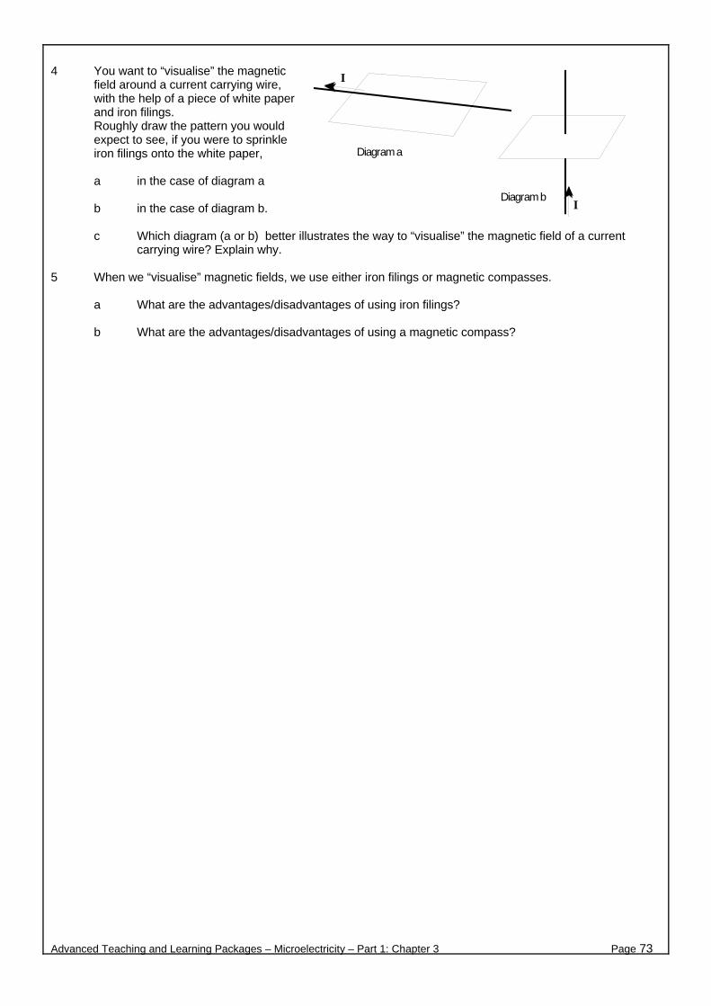
4 You want to “visualise” the magnetic
field around a current carrying wire, with the help of a piece of white paper and iron filings. Roughly draw the pattern you would expect to see, if you were to sprinkle iron filings onto the white paper,
a in the case of diagram a
b in the case of diagram b.
c Which diagram (a or b) better illustrates the way to “visualise” the magnetic field of a current
carrying wire? Explain why. 5 When we “visualise” magnetic fields, we use either iron filings or magnetic compasses.
a What are the advantages/disadvantages of using iron filings?
b What are the advantages/disadvantages of using a magnetic compass?
Advanced Teaching and Learning Packages – Microelectricity – Part 1: Chapter 3 Page 73
Diagram a
Diagram b
I
I

ACTIVITY 2 - THE SHAPE OF IT In this Activity, you will investigate the shape and the direction of the magnetic field lines, produced by an electric current. You will draw magnetic field lines for different directions of current. You will use the right hand rule to check the directions you found in your investigation and other examples. What you need micro-electricity kit, a cardboard roll (from a toilet paper cut in half),one circle of stiff paper, a pair of scissors, two different colour pens, prestik What to do 1 Set up your micro-electricity kit
components, as shown in the diagram alongside. Record the direction of the current in the straight vertical wire (upwards or downwards), when the circuit is closed.
2 Use one or two magnetic compasses
to help you draw the magnetic field lines around the vertical straight wire. Show the shape and the direction of the magnetic field lines, by drawing arrows on the stiff paper disk.
3 Reverse the current in the circuit.
Ia How will you do this? b Use a different colour pen to draw arrows on the same paper disk,
in order to show the shape and direction of the magnetic field lines for the new direction of the current.
4 In your own words, describe the shape and the direction of the magnetic
field lines around a straight current carrying conductor (wire in this case). 5 The figure on the right shows a trick which we use to “visualise” the
magnetic field around a current carrying conductor. It is called the right hand rule. a Describe this rule. b Use this rule to check the direction of the magnetic field lines you
found in steps 2 and 3. Are your results in agreement?
6 Use the right hand rule to determine the field around the current carrying conductors, shown on the left. The arrows indicate the direction of the current. 7 Follow the instructions in each of the diagrams.
Advanced Teaching and Learning Packages – Microelectricity – Part 1: Chapter 3 Page 74
Red
Black
2 cells in series
Place the circle of stiffpaper on top of thecardboard roll.
The roll should rest on thecomboplate, and the circleon the roll.
Connect one insulated wire here
The wire should passthrough the hole inthe middle of thecirrcle.
Vertical, straightinsulated wire
This wire isconnected to aspring inside theroll.
Circle cut out of stiff paper.
Cardboard roll
(d)
(a)
(b)
(c)

8 In the diagram on the right, explain why the
magnetic field at point A is stronger than at point B.
9 Look at the diagram on the right, and chose the correct answer. Explain your answer. a The magnetic field at point A is equal in
magnitude to the field at point B. b The magnetic field at point A is greater
than that at point B. c The magnetic field at point A is less
than that at point B. 10 Predict in which direction the compass
needle will deflect if you complete the circuit shown in the diagram on the right. Predict the direction of the compass needle if you reverse the direction of the current in the coil. Explain how you will do this. Set up the circuit to test your predictions.
Advanced Teaching and Learning Packages – Microelectricity – Part 1: Chapter 3 Page 75
Red
Black
Prestik or plasticine tokeep the coil vertical onthe desk
3V battery
Current
Draw the direction ofthe magnetic fieldlines
Wire
Current
Draw thedirection of thecurrent
(a)
(c)
(b)
(d)
Draw the direction ofthe magnetic fieldlines
(e)
Draw thedirection of thecurrent
Draw thedirection of thecurrent
AB
I
A
B
I
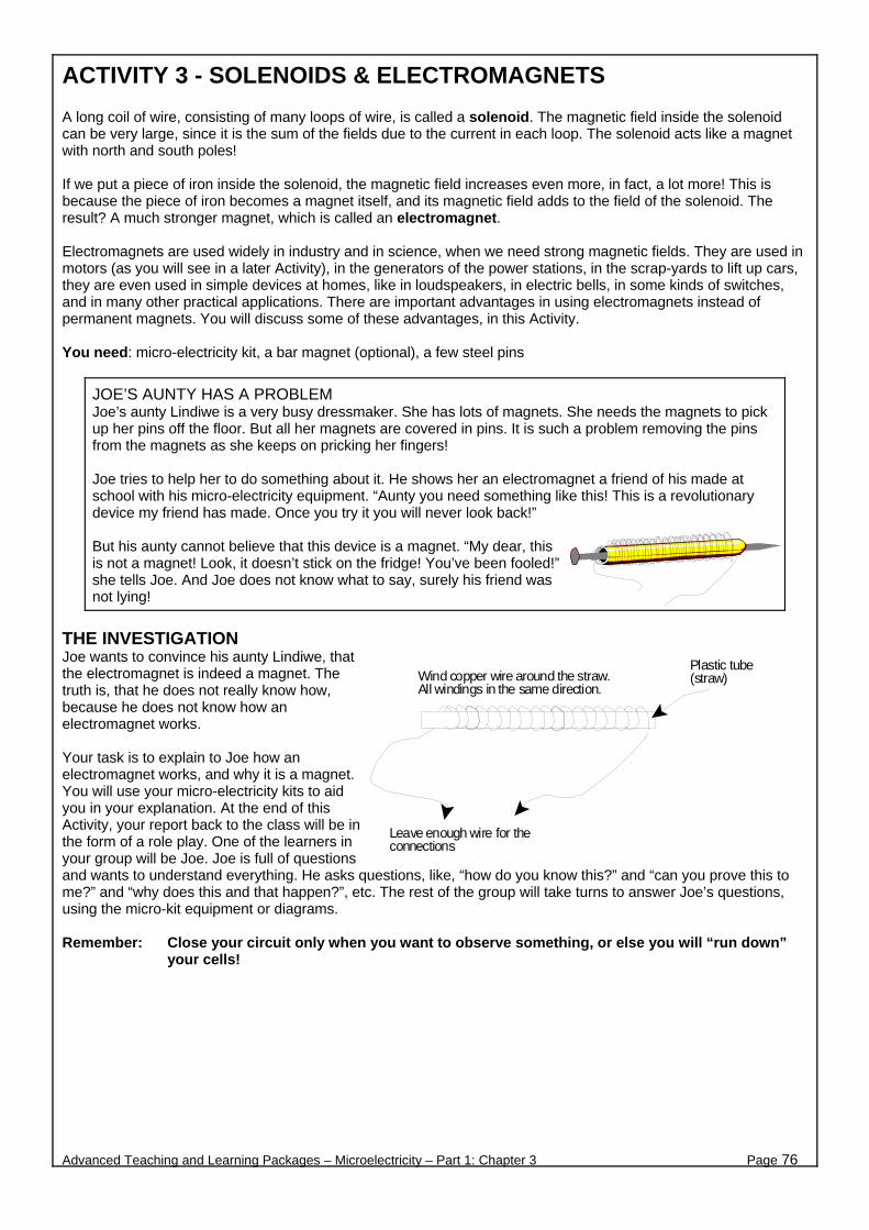
ACTIVITY 3 - SOLENOIDS & ELECTROMAGNETS A long coil of wire, consisting of many loops of wire, is called a solenoid. The magnetic field inside the solenoid can be very large, since it is the sum of the fields due to the current in each loop. The solenoid acts like a magnet with north and south poles! If we put a piece of iron inside the solenoid, the magnetic field increases even more, in fact, a lot more! This is because the piece of iron becomes a magnet itself, and its magnetic field adds to the field of the solenoid. The result? A much stronger magnet, which is called an electromagnet. Electromagnets are used widely in industry and in science, when we need strong magnetic fields. They are used in motors (as you will see in a later Activity), in the generators of the power stations, in the scrap-yards to lift up cars, they are even used in simple devices at homes, like in loudspeakers, in electric bells, in some kinds of switches, and in many other practical applications. There are important advantages in using electromagnets instead of permanent magnets. You will discuss some of these advantages, in this Activity. You need: micro-electricity kit, a bar magnet (optional), a few steel pins
JOE’S AUNTY HAS A PROBLEM Joe’s aunty Lindiwe is a very busy dressmaker. She has lots of magnets. She needs the magnets to pick up her pins off the floor. But all her magnets are covered in pins. It is such a problem removing the pins from the magnets as she keeps on pricking her fingers! Joe tries to help her to do something about it. He shows her an electromagnet a friend of his made at school with his micro-electricity equipment. “Aunty you need something like this! This is a revolutionary device my friend has made. Once you try it you will never look back!” But his aunty cannot believe that this device is a magnet. “My dear, this is not a magnet! Look, it doesn’t stick on the fridge! You’ve been fooled!” she tells Joe. And Joe does not know what to say, surely his friend was not lying!
THE INVESTIGATION Joe wants to convince his aunty Lindiwe, that the electromagnet is indeed a magnet. The truth is, that he does not really know how, because he does not know how an electromagnet works. Your task is to explain to Joe how an electromagnet works, and why it is a magnet. You will use your micro-electricity kits to aid you in your explanation. At the end of this Activity, your report back to the class will be in the form of a role play. One of the learners in your group will be Joe. Joe is full of questions and wants to understand everything. He asks questions, like, “how do you know this?” and “can you prove this to me?” and “why does this and that happen?”, etc. The rest of the group will take turns to answer Joe’s questions, using the micro-kit equipment or diagrams. Remember: Close your circuit only when you want to observe something, or else you will “run down”
your cells!
Advanced Teaching and Learning Packages – Microelectricity – Part 1: Chapter 3 Page 76
Wind copper wire around the straw.All windings in the same direction.
Leave enough wire for theconnections
Plastic tube(straw)
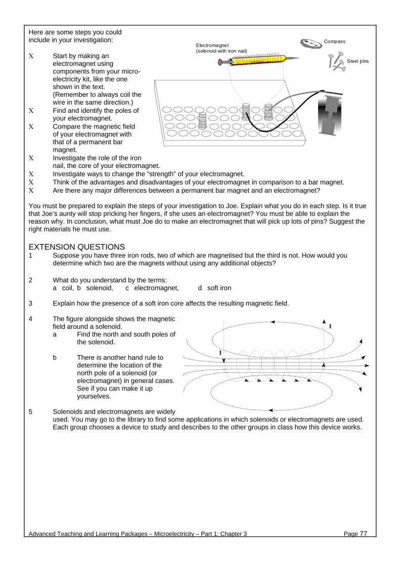
Here are some steps you could include in your investigation: Χ Start by making an
electromagnet using components from your micro-electricity kit, like the one shown in the text. (Remember to always coil the wire in the same direction.)
Χ Find and identify the poles of your electromagnet.
Χ Compare the magnetic field of your electromagnet with that of a permanent bar magnet.
Χ Investigate the role of the iron nail, the core of your electromagnet.
Χ Investigate ways to change the “strength” of your electromagnet. Χ Think of the advantages and disadvantages of your electromagnet in comparison to a bar magnet. Χ Are there any major differences between a permanent bar magnet and an electromagnet? You must be prepared to explain the steps of your investigation to Joe. Explain what you do in each step. Is it true that Joe’s aunty will stop pricking her fingers, if she uses an electromagnet? You must be able to explain the reason why. In conclusion, what must Joe do to make an electromagnet that will pick up lots of pins? Suggest the right materials he must use. EXTENSION QUESTIONS 1 Suppose you have three iron rods, two of which are magnetised but the third is not. How would you
determine which two are the magnets without using any additional objects? 2 What do you understand by the terms:
a coil, b solenoid, c electromagnet, d soft iron 3 Explain how the presence of a soft iron core affects the resulting magnetic field. 4 The figure alongside shows the magnetic
field around a solenoid. a Find the north and south poles of
the solenoid.
b There is another hand rule to determine the location of the north pole of a solenoid (or electromagnet) in general cases. See if you can make it up yourselves.
5 Solenoids and electromagnets are widely
used. You may go to the library to find some applications in which solenoids or electromagnets are used. Each group chooses a device to study and describes to the other groups in class how this device works.
Advanced Teaching and Learning Packages – Microelectricity – Part 1: Chapter 3 Page 77
Steel pins
CompassElectromagnet(solenoid with iron nail)
I
I
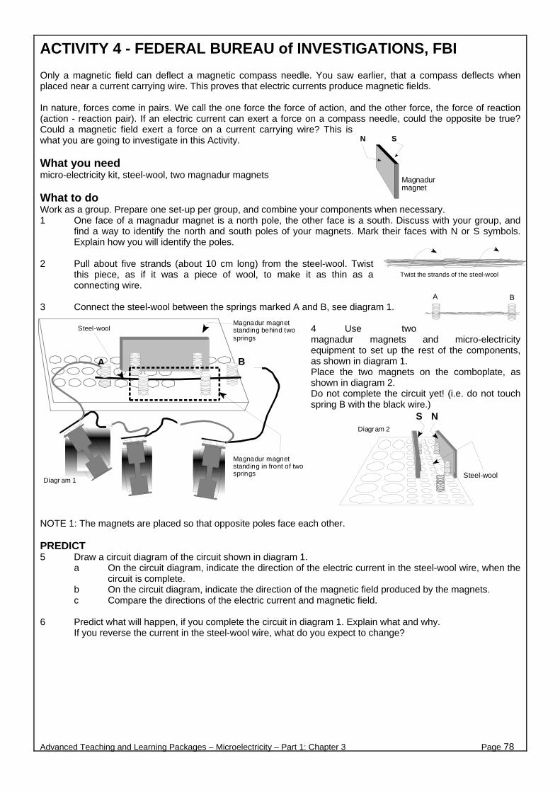
ACTIVITY 4 - FEDERAL BUREAU of INVESTIGATIONS, FBI
Only a magnetic field can deflect a magnetic compass needle. You saw earlier, that a compass deflects when placed near a current carrying wire. This proves that electric currents produce magnetic fields. In nature, forces come in pairs. We call the one force the force of action, and the other force, the force of reaction (action - reaction pair). If an electric current can exert a force on a compass needle, could the opposite be true? Could a magnetic field exert a force on a current carrying wire? This is what you are going to investigate in this Activity. What you need micro-electricity kit, steel-wool, two magnadur magnets What to do Work as a group. Prepare one set-up per group, and combine your components when necessary. 1 One face of a magnadur magnet is a north pole, the other face is a south. Discuss with your group, and
find a way to identify the north and south poles of your magnets. Mark their faces with N or S symbols. Explain how you will identify the poles.
2 Pull about five strands (about 10 cm long) from the steel-wool. Twist
this piece, as if it was a piece of wool, to make it as thin as a connecting wire.
3 Connect the steel-wool between the springs marked A and B, see diagram 1.
4 Use two magnadur magnets and micro-electricity equipment to set up the rest of the components, as shown in diagram 1. Place the two magnets on the comboplate, as shown in diagram 2. Do not complete the circuit yet! (i.e. do not touch spring B with the black wire.)
NOTE 1: The magnets are placed so that opposite poles face each other. PREDICT 5 Draw a circuit diagram of the circuit shown in diagram 1.
a On the circuit diagram, indicate the direction of the electric current in the steel-wool wire, when the circuit is complete.
b On the circuit diagram, indicate the direction of the magnetic field produced by the magnets. c Compare the directions of the electric current and magnetic field.
6 Predict what will happen, if you complete the circuit in diagram 1. Explain what and why.
If you reverse the current in the steel-wool wire, what do you expect to change?
Advanced Teaching and Learning Packages – Microelectricity – Part 1: Chapter 3 Page 78
N S
Magnadur magnet
A B
Twist the strands of the steel-wool
Magnadur magnetstanding behind twosprings
A B
Magnadur magnetstanding in front of twosprings
Steel-wool
Diagram 1
NS
Steel-wool
Diagram 2
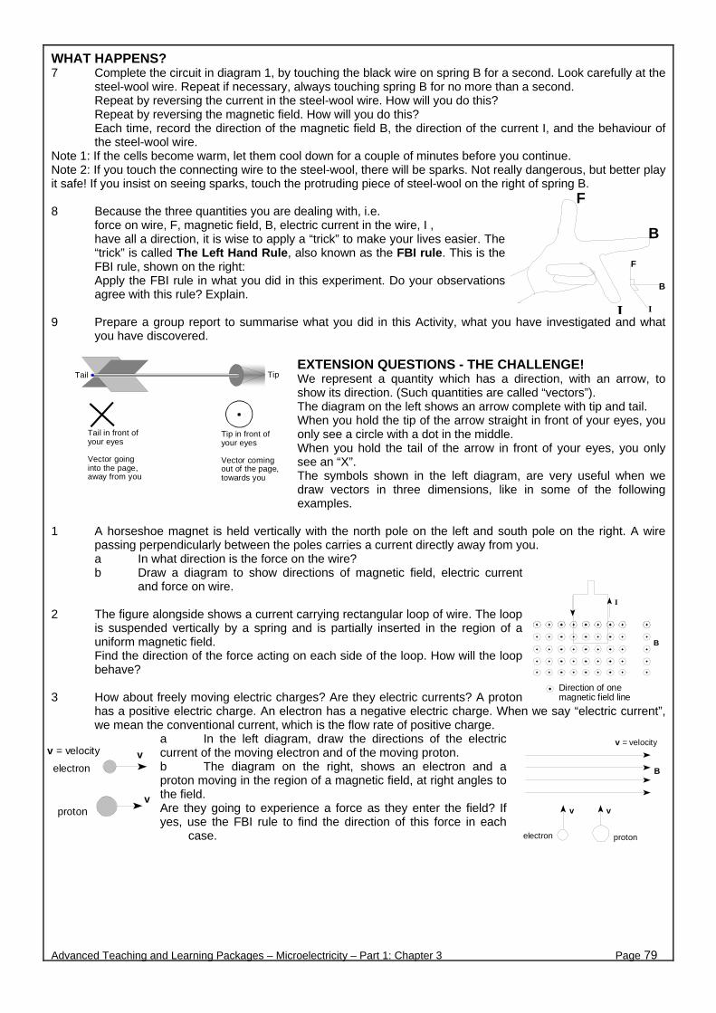
WHAT HAPPENS? 7 Complete the circuit in diagram 1, by touching the black wire on spring B for a second. Look carefully at the
steel-wool wire. Repeat if necessary, always touching spring B for no more than a second. Repeat by reversing the current in the steel-wool wire. How will you do this? Repeat by reversing the magnetic field. How will you do this? Each time, record the direction of the magnetic field B, the direction of the current I, and the behaviour of the steel-wool wire.
Note 1: If the cells become warm, let them cool down for a couple of minutes before you continue. Note 2: If you touch the connecting wire to the steel-wool, there will be sparks. Not really dangerous, but better play it safe! If you insist on seeing sparks, touch the protruding piece of steel-wool on the right of spring B. 8 Because the three quantities you are dealing with, i.e.
force on wire, F, magnetic field, B, electric current in the wire, I , have all a direction, it is wise to apply a “trick” to make your lives easier. The “trick” is called The Left Hand Rule, also known as the FBI rule. This is the FBI rule, shown on the right: Apply the FBI rule in what you did in this experiment. Do your observations agree with this rule? Explain.
9 Prepare a group report to summarise what you did in this Activity, what you have investigated and what
you have discovered. EXTENSION QUESTIONS - THE CHALLENGE! We represent a quantity which has a direction, with an arrow, to show its direction. (Such quantities are called “vectors”). The diagram on the left shows an arrow complete with tip and tail. When you hold the tip of the arrow straight in front of your eyes, you only see a circle with a dot in the middle. When you hold the tail of the arrow in front of your eyes, you only see an “X”. The symbols shown in the left diagram, are very useful when we draw vectors in three dimensions, like in some of the following examples.
1 A horseshoe magnet is held vertically with the north pole on the left and south pole on the right. A wire
passing perpendicularly between the poles carries a current directly away from you. a In what direction is the force on the wire? b Draw a diagram to show directions of magnetic field, electric current
and force on wire. 2 The figure alongside shows a current carrying rectangular loop of wire. The loop
is suspended vertically by a spring and is partially inserted in the region of a uniform magnetic field. Find the direction of the force acting on each side of the loop. How will the loop behave?
3 How about freely moving electric charges? Are they electric currents? A proton
has a positive electric charge. An electron has a negative electric charge. When we say “electric current”, we mean the conventional current, which is the flow rate of positive charge.
a In the left diagram, draw the directions of the electric current of the moving electron and of the moving proton. b The diagram on the right, shows an electron and a proton moving in the region of a magnetic field, at right angles to the field. Are they going to experience a force as they enter the field? If yes, use the FBI rule to find the direction of this force in each
case.
Advanced Teaching and Learning Packages – Microelectricity – Part 1: Chapter 3 Page 79
F
B
I
B
F
I
TipTail
Tail in front ofyour eyes
Vector goinginto the page,away from you
Tip in front ofyour eyes
Vector comingout of the page,towards you
B
I
Direction of onemagnetic field line
electron proton
vv
B
v = velocity
electron
protonv
vv = velocity

ACTIVITY 5 - ELECTRIC MOTOR 1 What you need micro-electricity kit, two magnadur magnets, sticky tape, a pair of scissors What to do 1 Use wire from the copper coil in
the micro-electricity kit. Use this wire to make a coil of about 10 to 15 windings. You may use the 9 V battery and wind the wire around it to make a coil. Leave about 5 cm of wire free from both ends of the coil.
2 Scrape the insulation from only the bottom half of both the ends of the wire. See diagrams. 3 The diagram below, shows how to set up the coil and the magnets on the comboplate. Connect the cell only when you are ready to test your motor.
The ends of the coil where you scrapped off the insulation, must touch the copper strips.
When your motor is ready and the cells connected, give the coil an initial push with your finger to get it started. If the coil does not turn, check that the contacts between copper strips and coil are good. You may have to scrape off some more insulation (always on the bottom half of the wire).
4 This is the complete motor. You must be prepared to identify the direction of the current in the coil and the polarity of the magnets. You must give the initial push in the right direction!
5 You must also be prepared to explain to the other learners in your group, why you only scrape the
insulation from the bottom half of the wire. What would happen if you were to scrape the insulation off all around the wire?
Advanced Teaching and Learning Packages – Microelectricity – Part 1: Chapter 3 Page 80
Scrape the insulation from thebottom half of the copper wire
Leave the insulation at the tophalf of the copper wire
Use sticky tape tokeep the coils in place
5 cm
Scrape the insulation off thebottom half of each end of thecopper wire
Leave the insulation at the tophalf of the copper wire
Copper wire magnified
Put two magnadurmagnets under the coil
B
Hang the coil on the copperstrips and give it a push
Copper strips bentinto this shape
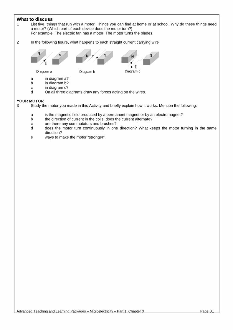
What to discuss 1 List five things that run with a motor. Things you can find at home or at school. Why do these things need
a motor? (Which part of each device does the motor turn?) For example: The electric fan has a motor. The motor turns the blades.
2 In the following figure, what happens to each straight current carrying wire
a in diagram a? b in diagram b? c in diagram c? d On all three diagrams draw any forces acting on the wires.
YOUR MOTOR 3 Study the motor you made in this Activity and briefly explain how it works. Mention the following:
a is the magnetic field produced by a permanent magnet or by an electromagnet? b the direction of current in the coils, does the current alternate? c are there any commutators and brushes? d does the motor turn continuously in one direction? What keeps the motor turning in the same
direction? e ways to make the motor “stronger”.
Advanced Teaching and Learning Packages – Microelectricity – Part 1: Chapter 3 Page 81
Diagram c
N S
Diagram b
N S
Diagram a
N S
II
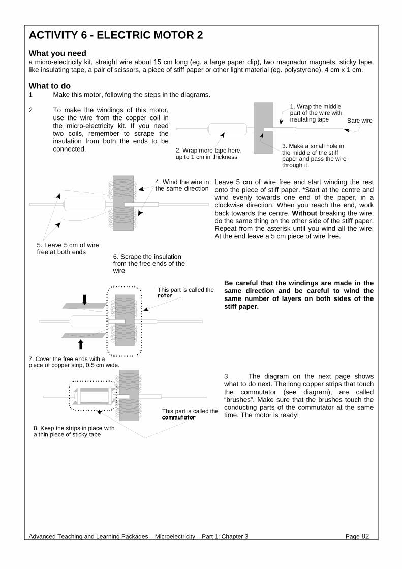
ACTIVITY 6 - ELECTRIC MOTOR 2 What you need a micro-electricity kit, straight wire about 15 cm long (eg. a large paper clip), two magnadur magnets, sticky tape, like insulating tape, a pair of scissors, a piece of stiff paper or other light material (eg. polystyrene), 4 cm x 1 cm. What to do 1 Make this motor, following the steps in the diagrams. 2 To make the windings of this motor,
use the wire from the copper coil in the micro-electricity kit. If you need two coils, remember to scrape the insulation from both the ends to be connected.
Leave 5 cm of wire free and start winding the rest onto the piece of stiff paper. *Start at the centre and wind evenly towards one end of the paper, in a clockwise direction. When you reach the end, work back towards the centre. Without breaking the wire, do the same thing on the other side of the stiff paper. Repeat from the asterisk until you wind all the wire. At the end leave a 5 cm piece of wire free.
Be careful that the windings are made in the same direction and be careful to wind the same number of layers on both sides of the stiff paper. 3 The diagram on the next page shows what to do next. The long copper strips that touch the commutator (see diagram), are called “brushes”. Make sure that the brushes touch the conducting parts of the commutator at the same time. The motor is ready!
Advanced Teaching and Learning Packages – Microelectricity – Part 1: Chapter 3 Page 82
1. Wrap the middlepart of the wire withinsulating tape
2. Wrap more tape here,up to 1 cm in thickness
3. Make a small hole inthe middle of the stiffpaper and pass the wirethrough it.
Bare wire
4. Wind the wire inthe same direction
5. Leave 5 cm of wirefree at both ends
6. Scrape the insulationfrom the free ends of thewire
7. Cover the free ends with apiece of copper strip, 0.5 cm wide.
8. Keep the strips in place witha thin piece of sticky tape
This part is called therotor
This part is called thecommutator

What to discuss YOUR OWN MOTORS 1 Compare the motors in Activities 5 and 6. Briefly explain how each one works. Mention the following:
a how the magnetic field is produced, by a permanent magnet or by an electromagnet? b the direction of current in the coils, does the current alternate? c are there any commutators and brushes? d does the motor turn continuously in one direction, and if so, what keeps the motor turning in the
same direction? e ways to make the motors “stronger”.
2 Explain the major difference in the way the two motors work. AND THERE IS MORE! There are more important and practical devices, which also take advantage of the force between a current and a magnetic field, other than the motors! Such devices are the galvanometers, the loudspeakers, the chart recorders, and many more! 3 The diagram shows the principle workings of a galvanometer, the basic
component of many meters (ammeters, voltmeters, ohmmeters.....)
a Use the hand rule to find the force acting on each side of the rectangular loop.
b Briefly explain how the pointer moves.
4 What energy transformations take place in an electric motor?
Advanced Teaching and Learning Packages – Microelectricity – Part 1: Chapter 3 Page 83
Put two magnadurmagnets under the coil
Hang the coil on thecopper strips
Copper strip bentinto this shape
Tape this end of the copperstrip on the table.The loose ends of the copperstrips touch the commutator.
Copper strips
Tape the copper stripon the comboplate
Spring attached tothe copper strip
Brushes

ACTIVITY 7 - CAN MAGNETISM PRODUCE ELECTRICITY? Electricity produces magnetism. An electric current produces a magnetic field. Is the opposite true? Can magnetism produce electricity? Can a magnetic field produce an electric current? What you need micro-electricity kit, multimeter, magnadur magnet (optional) C
To discuss before you start Rashay, Nicolas and Alex are all grade 10 learners. In their group they discuss the question: Can magnetism produce electricity?
Rashay all excited, says: “If electricity produces magnetism, then I am absolutely certain that magnetism can produce electricity. In nature, everything happens in pairs .... positive and negative, north and south, action and reaction.... you name it!”
Nicolas is even more excited. He says: “And what is even better, having a strong magnet at home, will produce all the electricity we need! No more electricity bills! Electrical energy for free with a magnet!”
Alex is not very excited! He says: “Nicolas, I wonder why nobody has thought of this before! We also know that we can’t get something out of nothing! Can a magnet, even a strong one, provide us with free energy? I find it hard to believe, it is against the laws of nature!”
So what do you think the answer is? Discuss the above comments with your group and add your own views. You can discuss this question again at the end of the Activity. What to do THE INVESTIGATION 1 Use a coil, an electromagnet (or a magnadur magnet), your multimeter, and any other component from
your micro-electricity kit which you might think would be of some use. Your task is to investigate if there is a way to produce (induce) an electric current in the coil. Hint: Compare what happens when:
< the electromagnet is stationary inside the coil < the electromagnet moves inside the coil < the coil moves along the length of the electromagnet
Explain how you will produce a magnetic field. Explain how you will know if a current is induced in the coil.
Something to consider in your group: If you manage to induce a current in the coil, do you expect this current to be large or small? On which scale would you set your multimeter? Try your plan out using your components.
2 If you do not have a multimeter, is there any other way to test if a current is induced in the coil? (using
equipment from your micro-electricity kit.) If you think yes, test this new way. 3 Summarise your conclusions and prepare a report back. In your report, mention ways (and test these ways
if possible), to increase the induced current in the coil. 4 It took more than 10 years after Oersted’s discovery, before two other scientists eventually succeeded to
induce an electric current this way. These scientists were the American Joseph Henry and the Englishman Michael Faraday. Working independently, they both found that it was possible to produce an electric current from a magnetic field. This phenomenon is called electromagnetic induction. Why do you think it took them so long?
Advanced Teaching and Learning Packages – Microelectricity – Part 1: Chapter 3 Page 84
Electromagnet
Multimeter
oil of copper wire
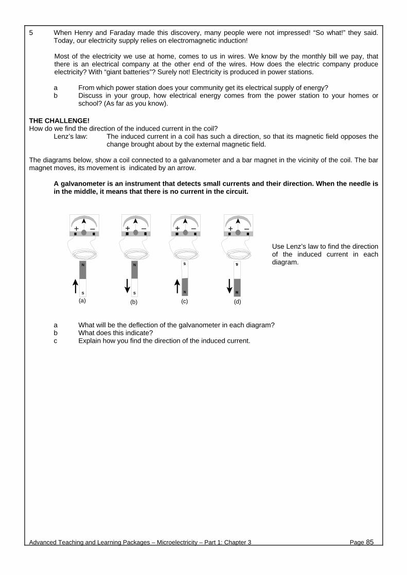
5 When Henry and Faraday made this discovery, many people were not impressed! “So what!” they said. Today, our electricity supply relies on electromagnetic induction!
Most of the electricity we use at home, comes to us in wires. We know by the monthly bill we pay, that there is an electrical company at the other end of the wires. How does the electric company produce electricity? With “giant batteries”? Surely not! Electricity is produced in power stations.
a From which power station does your community get its electrical supply of energy? b Discuss in your group, how electrical energy comes from the power station to your homes or
school? (As far as you know). THE CHALLENGE! How do we find the direction of the induced current in the coil?
Lenz’s law: The induced current in a coil has such a direction, so that its magnetic field opposes the change brought about by the external magnetic field.
The diagrams below, show a coil connected to a galvanometer and a bar magnet in the vicinity of the coil. The bar magnet moves, its movement is indicated by an arrow.
A galvanometer is an instrument that detects small currents and their direction. When the needle is in the middle, it means that there is no current in the circuit.
Use Lenz’s law to find the direction of the induced current in each diagram.
a What will be the deflection of the galvanometer in each diagram? b What does this indicate? c Explain how you find the direction of the induced current.
Advanced Teaching and Learning Packages – Microelectricity – Part 1: Chapter 3 Page 85
N
S
+ −
N
S
(a) (d)(c)(b)
+ − + − + −

CHAPTER 4
Advanced Teaching and Learning Packages – Microelectricity – Part 1: Chapter 3 Page 86
A. ELECTRIC CURRENT & ELECTRICAL RESISTANCE
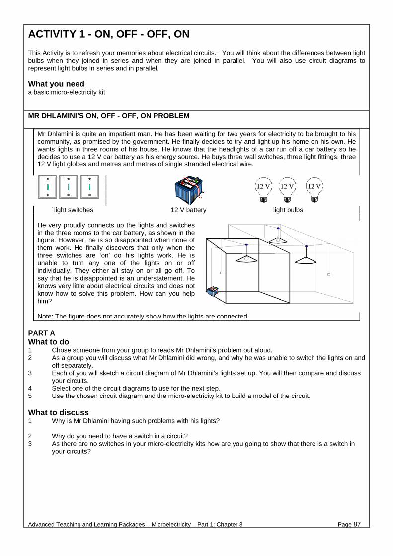
ACTIVITY 1 - ON, OFF - OFF, ON
This Activity is to refresh your memories about electrical circuits. You will think about the differences between light bulbs when they joined in series and when they are joined in parallel. You will also use circuit diagrams to represent light bulbs in series and in parallel. What you need a basic micro-electricity kit
MR DHLAMINI’S ON, OFF - OFF, ON PROBLEM
Mr Dhlamini is quite an impatient man. He has been waiting for two years for electricity to be brought to his community, as promised by the government. He finally decides to try and light up his home on his own. He wants lights in three rooms of his house. He knows that the headlights of a car run off a car battery so he decides to use a 12 V car battery as his energy source. He buys three wall switches, three light fittings, three 12 V light globes and metres and metres of single stranded electrical wire.
`light switches 12 V battery light bulbs He very proudly connects up the lights and switches in the three rooms to the car battery, as shown in the figure. However, he is so disappointed when none of them work. He finally discovers that only when the three switches are ‘on’ do his lights work. He is unable to turn any one of the lights on or off individually. They either all stay on or all go off. To say that he is disappointed is an understatement. He knows very little about electrical circuits and does not know how to solve this problem. How can you help him? Note: The figure does not accurately show how the lights are connected.
PART A What to do 1 Chose someone from your group to reads Mr Dhlamini’s problem out aloud. 2 As a group you will discuss what Mr Dhlamini did wrong, and why he was unable to switch the lights on and
off separately. 3 Each of you will sketch a circuit diagram of Mr Dhlamini’s lights set up. You will then compare and discuss
your circuits. 4 Select one of the circuit diagrams to use for the next step. 5 Use the chosen circuit diagram and the micro-electricity kit to build a model of the circuit. What to discuss 1 Why is Mr Dhlamini having such problems with his lights? 2 Why do you need to have a switch in a circuit? 3 As there are no switches in your micro-electricity kits how are you going to show that there is a switch in
your circuits?
Advanced Teaching and Learning Packages – Microelectricity – Part 1: Chapter 3 Page 87
12 V 12 V 12 V
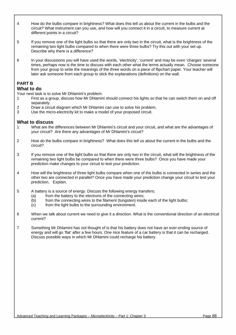
4 How do the bulbs compare in brightness? What does this tell us about the current in the bulbs and the
circuit? What instrument can you use, and how will you connect it in a circuit, to measure current at different points in a circuit?
5 If you remove one of the light bulbs so that there are only two in the circuit, what is the brightness of the
remaining two light bulbs compared to when there were three bulbs? Try this out with your set up. Describe why there is a difference?
6 In your discussions you will have used the words, ‘electricity’, ‘current’ and may be even ‘charges’ several
times, perhaps now is the time to discuss with each other what the terms actually mean. Choose someone from your group to write the meanings of the three words on a piece of flipchart paper. Your teacher will later ask someone from each group to stick the explanations (definitions) on the wall.
PART B What to do Your next task is to solve Mr Dhlamini’s problem. 1 First as a group, discuss how Mr Dhlamini should connect his lights so that he can switch them on and off
separately. 2 Draw a circuit diagram which Mr Dhlamini can use to solve his problem. 3 Use the micro-electricity kit to make a model of your proposed circuit. What to discuss 1 What are the differences between Mr Dhlamini’s circuit and your circuit, and what are the advantages of
your circuit? Are there any advantages of Mr Dhlamini’s circuit? 2 How do the bulbs compare in brightness? What does this tell us about the current in the bulbs and the
circuit? 3 If you remove one of the light bulbs so that there are only two in the circuit, what will the brightness of the
remaining two light bulbs be compared to when there were three bulbs? Once you have made your prediction make changes to your circuit to test your prediction.
4 How will the brightness of three light bulbs compare when one of the bulbs is connected in series and the
other two are connected in parallel? Once you have made your prediction change your circuit to test your prediction. Explain.
5 A battery is a source of energy. Discuss the following energy transfers;
(a) from the battery to the electrons of the connecting wires; (b) from the connecting wires to the filament (tungsten) inside each of the light bulbs; (c) from the light bulbs to the surrounding environment.
6 When we talk about current we need to give it a direction. What is the conventional direction of an electrical
current?
7 Something Mr Dhlamini has not thought of is that his battery does not have an ever-ending source of energy and will go ‘flat’ after a few hours. One nice feature of a car battery is that it can be recharged. Discuss possible ways in which Mr Dhlamini could recharge his battery.
Advanced Teaching and Learning Packages – Microelectricity – Part 1: Chapter 3 Page 88
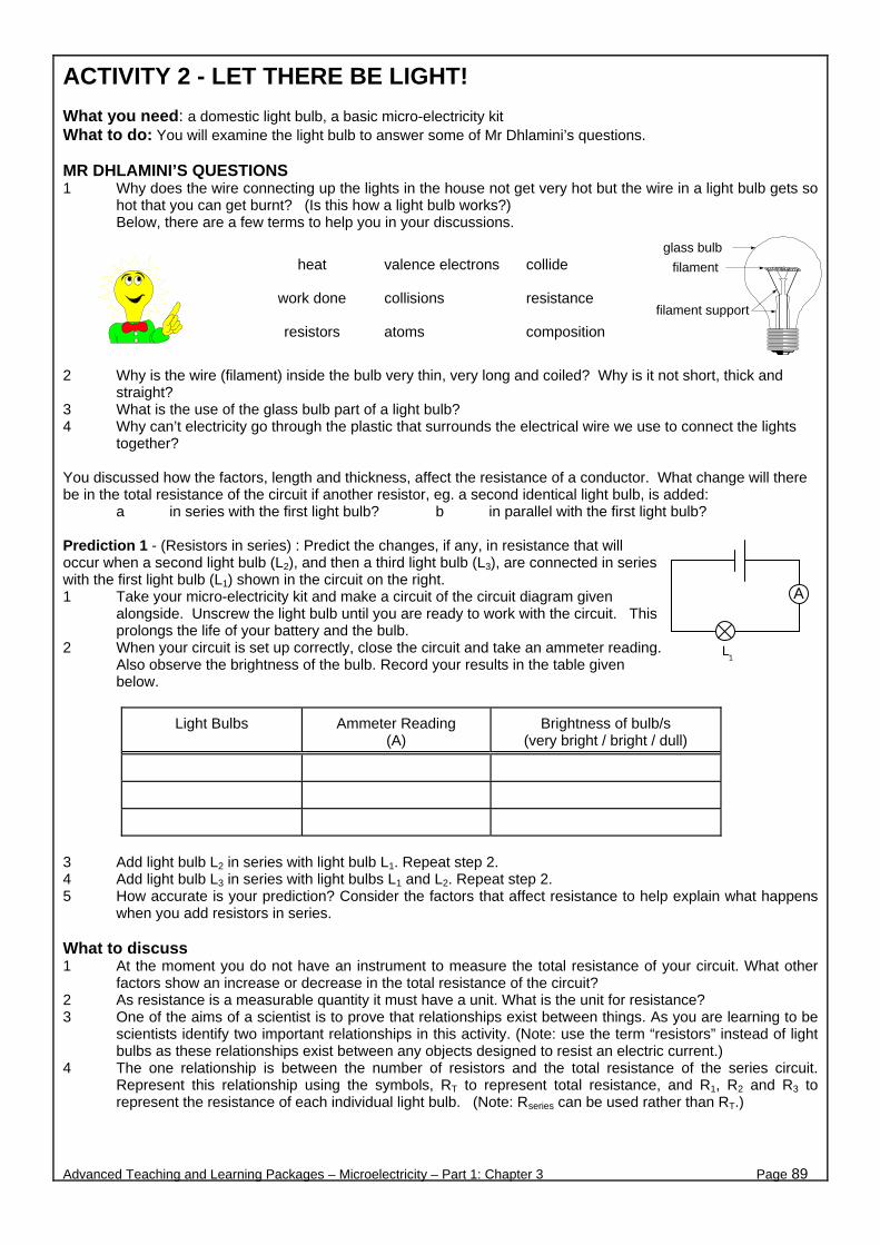
ACTIVITY 2 - LET THERE BE LIGHT! What you need: a domestic light bulb, a basic micro-electricity kit What to do: You will examine the light bulb to answer some of Mr Dhlamini’s questions. MR DHLAMINI’S QUESTIONS 1 Why does the wire connecting up the lights in the house not get very hot but the wire in a light bulb gets so
hot that you can get burnt? (Is this how a light bulb works?) Below, there are a few terms to help you in your discussions.
filament support
filament
glass bulb
2 Why is the wire (filament) inside the bulb very thin, very long and coiled? Why is it not short, thick and straight?
3 What is the use of the glass bulb part of a light bulb? 4 Why can’t electricity go through the plastic that surrounds the electrical wire we use to connect the lights
together? You discussed how the factors, length and thickness, affect the resistance of a conductor. What change will there be in the total resistance of the circuit if another resistor, eg. a second identical light bulb, is added:
a in series with the first light bulb? b in parallel with the first light bulb? Prediction 1 - (Resistors in series) : Predict the changes, if any, in resistance that will occur when a second light bulb (L2), and then a third light bulb (L3), are connected in series with the first light bulb (L1) shown in the circuit on the right. 1 Take your micro-electricity kit and make a circuit of the circuit diagram given
alongside. Unscrew the light bulb until you are ready to work with the circuit. This prolongs the life of your battery and the bulb.
2 When your circuit is set up correctly, close the circuit and take an ammeter reading. Also observe the brightness of the bulb. Record your results in the table given below.
Light Bulbs Ammeter Reading (A)
Brightness of bulb/s (very bright / bright / dull)
3 Add light bulb L2 in series with light bulb L1. Repeat step 2. 4 Add light bulb L3 in series with light bulbs L1 and L2. Repeat step 2. 5 How accurate is your prediction? Consider the factors that affect resistance to help explain what happens
when you add resistors in series. What to discuss 1 At the moment you do not have an instrument to measure the total resistance of your circuit. What other
factors show an increase or decrease in the total resistance of the circuit? 2 As resistance is a measurable quantity it must have a unit. What is the unit for resistance? 3 One of the aims of a scientist is to prove that relationships exist between things. As you are learning to be
scientists identify two important relationships in this activity. (Note: use the term “resistors” instead of light bulbs as these relationships exist between any objects designed to resist an electric current.)
4 The one relationship is between the number of resistors and the total resistance of the series circuit. Represent this relationship using the symbols, RT to represent total resistance, and R1, R2 and R3 to represent the resistance of each individual light bulb. (Note: Rseries can be used rather than RT.)
Advanced Teaching and Learning Packages – Microelectricity – Part 1: Chapter 3 Page 89
heat valence electrons collide
work done collisions resistance
resistors atoms composition
A
L1
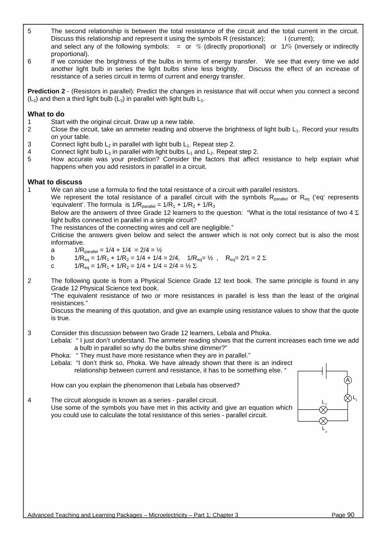
5 The second relationship is between the total resistance of the circuit and the total current in the circuit. Discuss this relationship and represent it using the symbols R (resistance); I (current); and select any of the following symbols: = or % (directly proportional) or 1/% (inversely or indirectly proportional).
6 If we consider the brightness of the bulbs in terms of energy transfer. We see that every time we add another light bulb in series the light bulbs shine less brightly. Discuss the effect of an increase of resistance of a series circuit in terms of current and energy transfer.
Prediction 2 - (Resistors in parallel): Predict the changes in resistance that will occur when you connect a second (L2) and then a third light bulb (L3) in parallel with light bulb L1. What to do 1 Start with the original circuit. Draw up a new table. 2 Close the circuit, take an ammeter reading and observe the brightness of light bulb L1. Record your results
on your table. 3 Connect light bulb L2 in parallel with light bulb L1. Repeat step 2. 4 Connect light bulb L3 in parallel with light bulbs L1 and L2. Repeat step 2. 5 How accurate was your prediction? Consider the factors that affect resistance to help explain what
happens when you add resistors in parallel in a circuit. What to discuss 1 We can also use a formula to find the total resistance of a circuit with parallel resistors.
We represent the total resistance of a parallel circuit with the symbols Rparallel or Req (‘eq’ represents ‘equivalent’. The formula is 1/Rparallel = 1/R1 + 1/R2 + 1/R3 Below are the answers of three Grade 12 learners to the question: “What is the total resistance of two 4 Σ light bulbs connected in parallel in a simple circuit? The resistances of the connecting wires and cell are negligible.” Criticise the answers given below and select the answer which is not only correct but is also the most informative. a 1/Rparallel = 1/4 + 1/4 = 2/4 = ½ b 1/Req = 1/R1 + 1/R2 = 1/4 + 1/4 = 2/4, 1/Req= ½ , Req= 2/1 = 2 Σ c 1/Req = 1/R1 + 1/R2 = 1/4 + 1/4 = 2/4 = ½ Σ
2 The following quote is from a Physical Science Grade 12 text book. The same principle is found in any
Grade 12 Physical Science text book. “The equivalent resistance of two or more resistances in parallel is less than the least of the original resistances.” Discuss the meaning of this quotation, and give an example using resistance values to show that the quote is true.
3 Consider this discussion between two Grade 12 learners, Lebala and Phoka.
Lebala: “ I just don’t understand. The ammeter reading shows that the current increases each time we add a bulb in parallel so why do the bulbs shine dimmer?”
Phoka: “ They must have more resistance when they are in parallel.” Lebala: “I don’t think so, Phoka. We have already shown that there is an indirect
relationship between current and resistance, it has to be something else. “ How can you explain the phenomenon that Lebala has observed?
4 The circuit alongside is known as a series - parallel circuit.
Use some of the symbols you have met in this activity and give an equation which you could use to calculate the total resistance of this series - parallel circuit.
Advanced Teaching and Learning Packages – Microelectricity – Part 1: Chapter 3 Page 90
L1
A
L2
L3

HOMEWORK One of the aims of this activity was to get you to understand the relationships between the total resistance of a circuit and the resistances of the light bulbs when they are connected differently. Here are a few problems for you to solve using the equations you derived in the activity. Note: the resistances of the connecting wires and the cell are negligible. 1 Give the resistance of the circuit on the right.
2 Calculate the resistance of each of the circuits given below.
(a) (b) (c) 3 When switches are closed or opened they cause changes to the circuit.
a Study each of the following circuits and predict whether the total circuit resistance increases / stays the same / decreases when switch S1 is closed.
b Calculate the total circuit resistance before and after the changes and see whether your results
support your predictions.
(i) (ii) (iii)
Advanced Teaching and Learning Packages – Microelectricity – Part 1: Chapter 3 Page 91
L2L1 L3
2 2 2
S1
2
2S
1
2
2
S2
3
3
3
2
4 4
2
2 2
S1
2
2

4 Understanding the indirect relationship between current and resistance is very important.
(a) Without the use of any equations, but using ratios, determine the readings on the ammeters in the circuits. The reading on A1 in each circuit is 4 A. Enter the values onto your sheet.
(i)
A2 = ____________ A3 = ____________
(ii)
A1
2 ohms2 ohmsA2
A4
4 ohms
A3
A2 = ____________ A3 = ____________ A4 = ____________
( iii)
A1
1ohm
3 ohmsA2
A3
A2 = ____________ A3 = ____________
Advanced Teaching and Learning Packages – Microelectricity – Part 1: Chapter 3 Page 92
A1
2 ohms
2 ohmsA2
A3
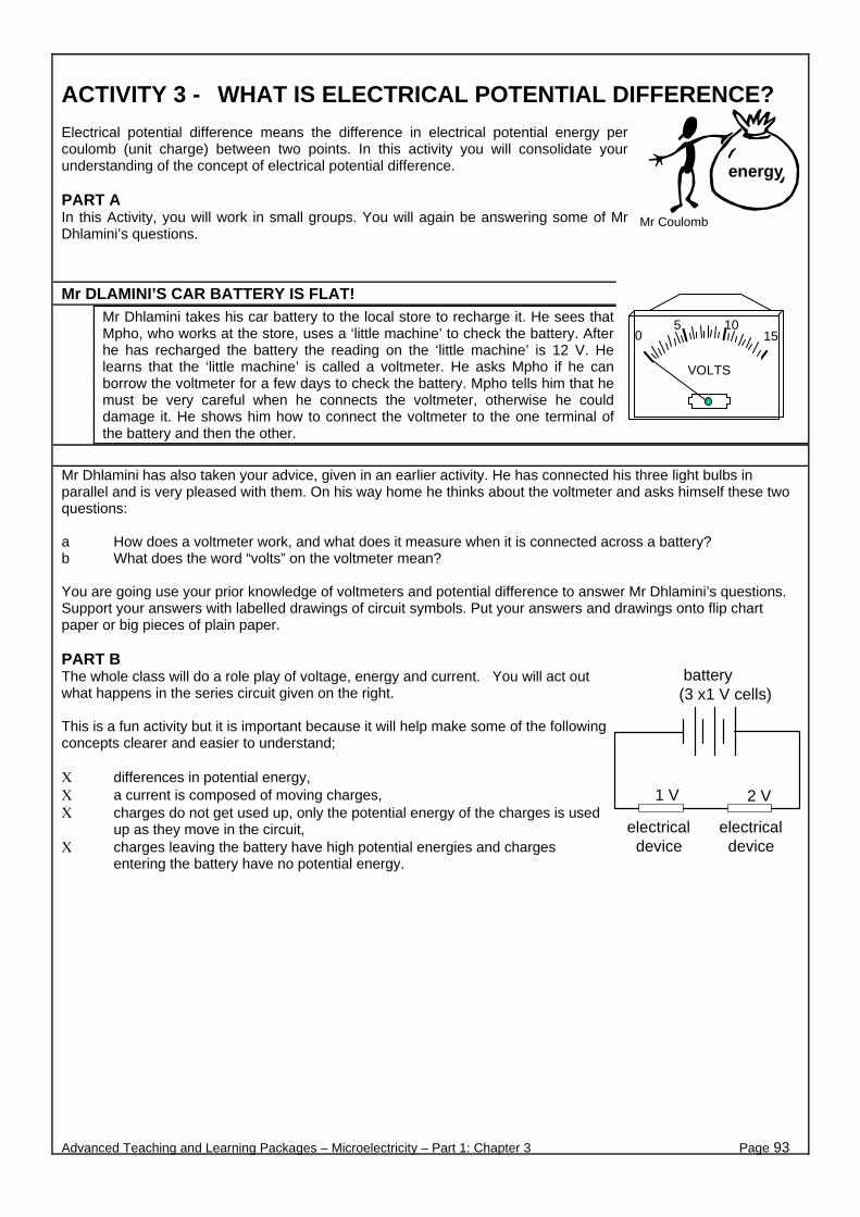
ACTIVITY 3 - WHAT IS ELECTRICAL POTENTIAL DIFFERENCE? Electrical potential difference means the difference in electrical potential energy per coulomb (unit charge) between two points. In this activity you will consolidate your understanding of the concept of electrical potential difference. PART A In this Activity, you will work in small groups. You will again be answering some of Mr Dhlamini’s questions.
Mr DLAMINI’S CAR BATTERY IS FLAT! Mr Dhlamini takes his car battery to the local store to recharge it. He sees that Mpho, who works at the store, uses a ‘little machine’ to check the battery. After he has recharged the battery the reading on the ‘little machine’ is 12 V. He learns that the ‘little machine’ is called a voltmeter. He asks Mpho if he can borrow the voltmeter for a few days to check the battery. Mpho tells him that he must be very careful when he connects the voltmeter, otherwise he could damage it. He shows him how to connect the voltmeter to the one terminal of the battery and then the other.
Mr Dhlamini has also taken your advice, given in an earlier activity. He has connected his three light bulbs in parallel and is very pleased with them. On his way home he thinks about the voltmeter and asks himself these two questions: a How does a voltmeter work, and what does it measure when it is connected across a battery? b What does the word “volts” on the voltmeter mean? You are going use your prior knowledge of voltmeters and potential difference to answer Mr Dhlamini’s questions. Support your answers with labelled drawings of circuit symbols. Put your answers and drawings onto flip chart paper or big pieces of plain paper. PART B The whole class will do a role play of voltage, energy and current. You will act out what happens in the series circuit given on the right. This is a fun activity but it is important because it will help make some of the following concepts clearer and easier to understand; Χ differences in potential energy, Χ a current is composed of moving charges, Χ charges do not get used up, only the potential energy of the charges is used
up as they move in the circuit, Χ charges leaving the battery have high potential energies and charges
entering the battery have no potential energy.
Advanced Teaching and Learning Packages – Microelectricity – Part 1: Chapter 3 Page 93
5 100 15
VOLTS
energy
Mr Coulomb
battery(3 x1 V cells)
electrical device
electrical device
1 V 2 V
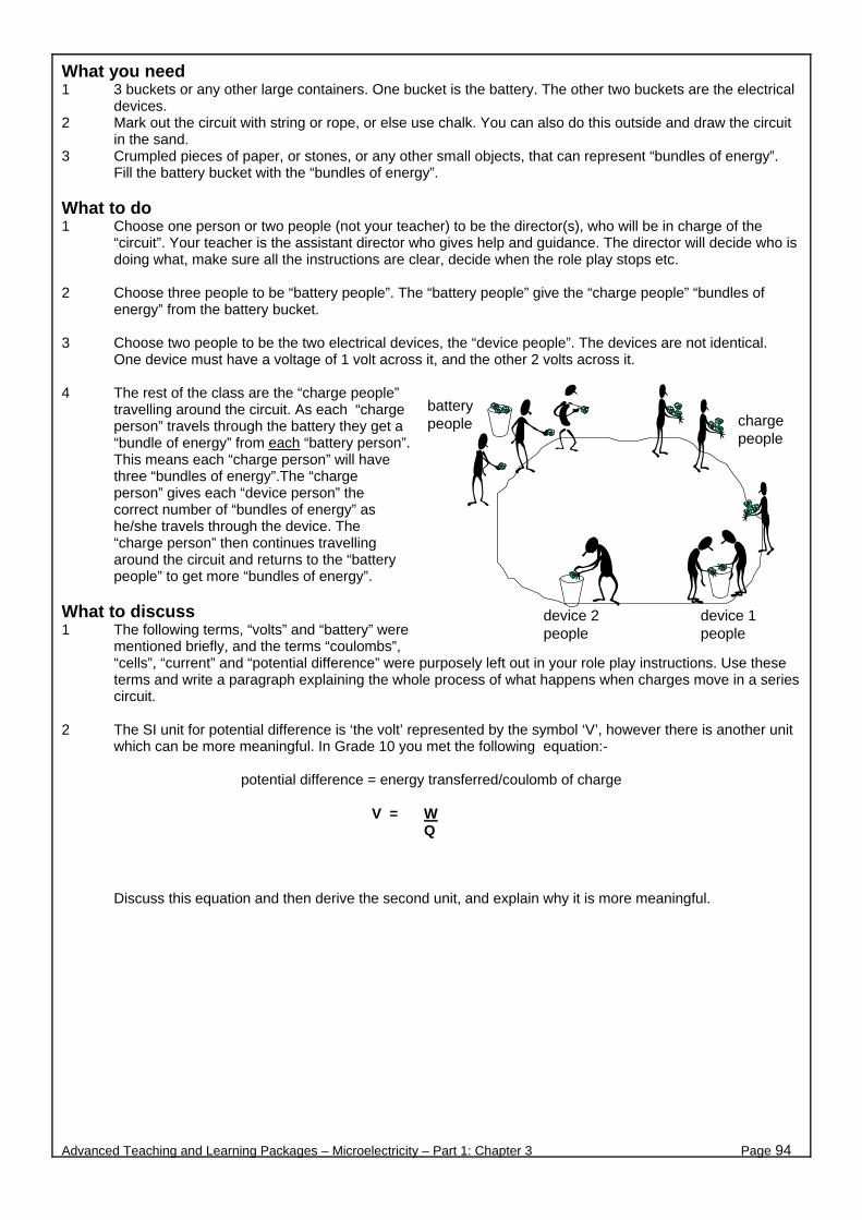
What you need 1 3 buckets or any other large containers. One bucket is the battery. The other two buckets are the electrical
devices. 2 Mark out the circuit with string or rope, or else use chalk. You can also do this outside and draw the circuit
in the sand. 3 Crumpled pieces of paper, or stones, or any other small objects, that can represent “bundles of energy”.
Fill the battery bucket with the “bundles of energy”. What to do 1 Choose one person or two people (not your teacher) to be the director(s), who will be in charge of the
“circuit”. Your teacher is the assistant director who gives help and guidance. The director will decide who is doing what, make sure all the instructions are clear, decide when the role play stops etc.
2 Choose three people to be “battery people”. The “battery people” give the “charge people” “bundles of
energy” from the battery bucket. 3 Choose two people to be the two electrical devices, the “device people”. The devices are not identical.
One device must have a voltage of 1 volt across it, and the other 2 volts across it. 4 The rest of the class are the “charge people”
travelling around the circuit. As each “charge person” travels through the battery they get a “bundle of energy” from each “battery person”. This means each “charge person” will have three “bundles of energy”.The “charge person” gives each “device person” the correct number of “bundles of energy” as he/she travels through the device. The “charge person” then continues travelling around the circuit and returns to the “battery people” to get more “bundles of energy”.
What to discuss 1 The following terms, “volts” and “battery” were
mentioned briefly, and the terms “coulombs”, “cells”, “current” and “potential difference” were purposely left out in your role play instructions. Use these terms and write a paragraph explaining the whole process of what happens when charges move in a series circuit.
2 The SI unit for potential difference is ‘the volt’ represented by the symbol ‘V’, however there is another unit
which can be more meaningful. In Grade 10 you met the following equation:-
potential difference = energy transferred/coulomb of charge
Discuss this equation and then derive the second unit, and explain why it is more meaningful.
Advanced Teaching and Learning Packages – Microelectricity – Part 1: Chapter 3 Page 94
V = W Q
battery people
device 1 people
device 2 people
charge people
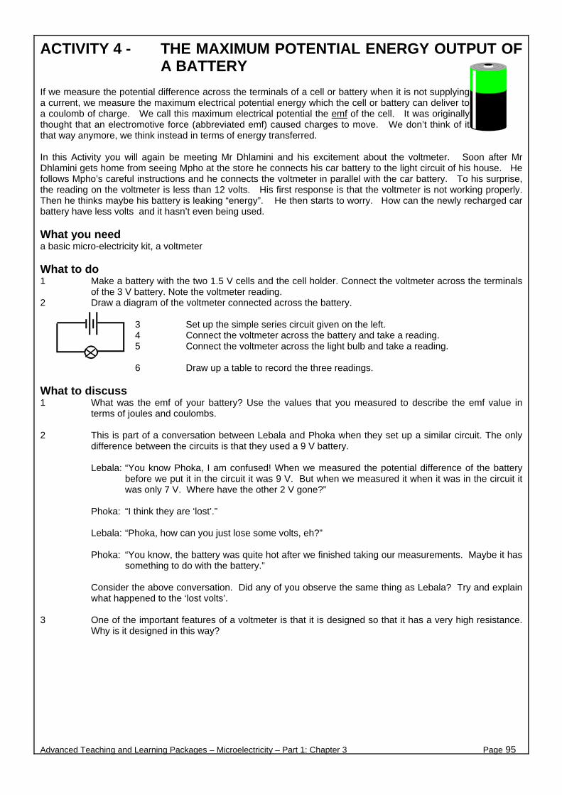
ACTIVITY 4 - THE MAXIMUM POTENTIAL ENERGY OUTPUT OF A BATTERY
If we measure the potential difference across the terminals of a cell or battery when it is not supplying a current, we measure the maximum electrical potential energy which the cell or battery can deliver to a coulomb of charge. We call this maximum electrical potential the emf of the cell. It was originally thought that an electromotive force (abbreviated emf) caused charges to move. We don’t think of it that way anymore, we think instead in terms of energy transferred. In this Activity you will again be meeting Mr Dhlamini and his excitement about the voltmeter. Soon after Mr Dhlamini gets home from seeing Mpho at the store he connects his car battery to the light circuit of his house. He follows Mpho’s careful instructions and he connects the voltmeter in parallel with the car battery. To his surprise, the reading on the voltmeter is less than 12 volts. His first response is that the voltmeter is not working properly. Then he thinks maybe his battery is leaking “energy”. He then starts to worry. How can the newly recharged car battery have less volts and it hasn’t even being used. What you need a basic micro-electricity kit, a voltmeter What to do 1 Make a battery with the two 1.5 V cells and the cell holder. Connect the voltmeter across the terminals
of the 3 V battery. Note the voltmeter reading. 2 Draw a diagram of the voltmeter connected across the battery.
3 Set up the simple series circuit given on the left. 4 Connect the voltmeter across the battery and take a reading. 5 Connect the voltmeter across the light bulb and take a reading. 6 Draw up a table to record the three readings.
What to discuss 1 What was the emf of your battery? Use the values that you measured to describe the emf value in
terms of joules and coulombs. 2 This is part of a conversation between Lebala and Phoka when they set up a similar circuit. The only
difference between the circuits is that they used a 9 V battery.
Lebala: “You know Phoka, I am confused! When we measured the potential difference of the battery before we put it in the circuit it was 9 V. But when we measured it when it was in the circuit it was only 7 V. Where have the other 2 V gone?”
Phoka: “I think they are ‘lost’.”
Lebala: “Phoka, how can you just lose some volts, eh?”
Phoka: “You know, the battery was quite hot after we finished taking our measurements. Maybe it has
something to do with the battery.”
Consider the above conversation. Did any of you observe the same thing as Lebala? Try and explain what happened to the ‘lost volts’.
3 One of the important features of a voltmeter is that it is designed so that it has a very high resistance.
Why is it designed in this way?
Advanced Teaching and Learning Packages – Microelectricity – Part 1: Chapter 3 Page 95
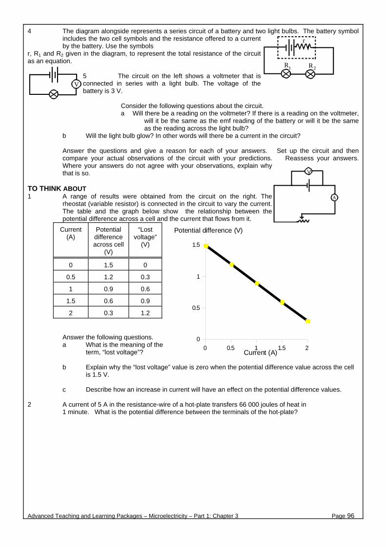
4 The diagram alongside represents a series circuit of a battery and two light bulbs. The battery symbol includes the two cell symbols and the resistance offered to a current by the battery. Use the symbols
r, R1 and R2 given in the diagram, to represent the total resistance of the circuit as an equation.
5 The circuit on the left shows a voltmeter that is connected in series with a light bulb. The voltage of the battery is 3 V.
Consider the following questions about the circuit. a Will there be a reading on the voltmeter? If there is a reading on the voltmeter,
will it be the same as the emf reading of the battery or will it be the same as the reading across the light bulb?
b Will the light bulb glow? In other words will there be a current in the circuit?
Answer the questions and give a reason for each of your answers. Set up the circuit and then compare your actual observations of the circuit with your predictions. Reassess your answers. Where your answers do not agree with your observations, explain why that is so.
TO THINK ABOUT 1 A range of results were obtained from the circuit on the right. The
rheostat (variable resistor) is connected in the circuit to vary the current. The table and the graph below show the relationship between the potential difference across a cell and the current that flows from it.
Current (A)
Potential difference across cell
(V)
“Lost voltage”
(V)
0 1.5 0
0.5 1.2 0.3
1 0.9 0.6
1.5 0.6 0.9
2 0.3 1.2
Answer the following questions. a What is the meaning of the
term, “lost voltage”?
b Explain why the “lost voltage” value is zero when the potential difference value across the cell is 1.5 V.
c Describe how an increase in current will have an effect on the potential difference values.
2 A current of 5 A in the resistance-wire of a hot-plate transfers 66 000 joules of heat in
1 minute. What is the potential difference between the terminals of the hot-plate?
Advanced Teaching and Learning Packages – Microelectricity – Part 1: Chapter 3 Page 96
r
R R1 2
V
V
A
0 0.5 1 1.5 20
0.5
1
1.5
Current (A)
Potential difference (V)
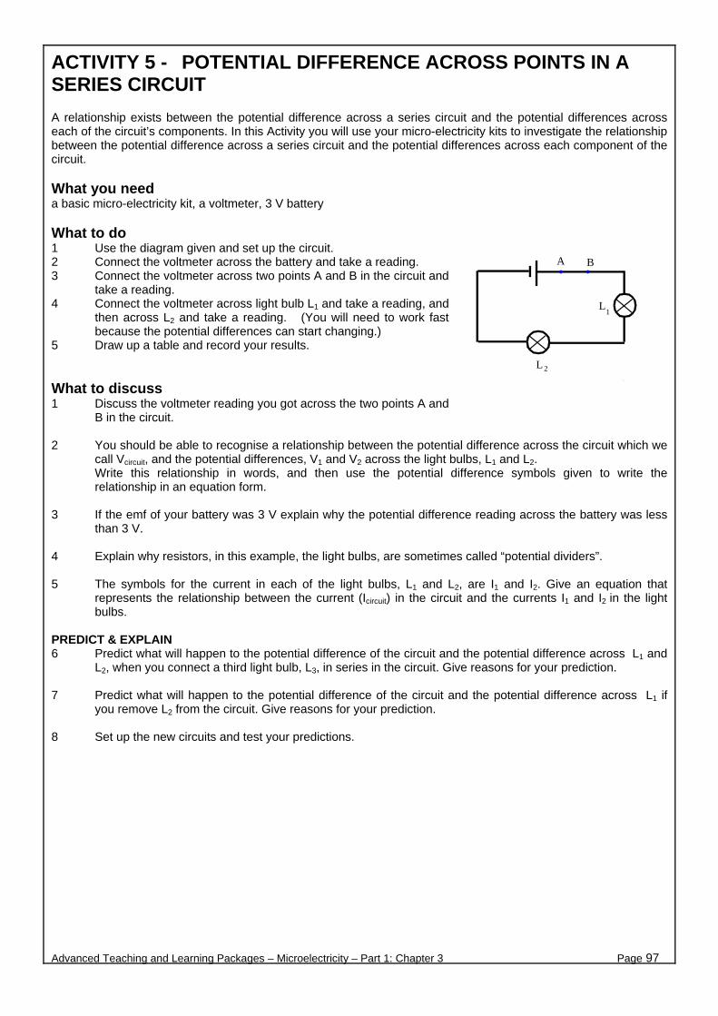
ACTIVITY 5 - POTENTIAL DIFFERENCE ACROSS POINTS IN A SERIES CIRCUIT A relationship exists between the potential difference across a series circuit and the potential differences across each of the circuit’s components. In this Activity you will use your micro-electricity kits to investigate the relationship between the potential difference across a series circuit and the potential differences across each component of the circuit. What you need a basic micro-electricity kit, a voltmeter, 3 V battery What to do 1 Use the diagram given and set up the circuit. 2 Connect the voltmeter across the battery and take a reading. 3 Connect the voltmeter across two points A and B in the circuit and
take a reading. 4 Connect the voltmeter across light bulb L1 and take a reading, and
then across L2 and take a reading. (You will need to work fast because the potential differences can start changing.)
5 Draw up a table and record your results. What to discuss 1 Discuss the voltmeter reading you got across the two points A and
B in the circuit. 2 You should be able to recognise a relationship between the potential difference across the circuit which we
call Vcircuit, and the potential differences, V1 and V2 across the light bulbs, L1 and L2. Write this relationship in words, and then use the potential difference symbols given to write the relationship in an equation form.
3 If the emf of your battery was 3 V explain why the potential difference reading across the battery was less
than 3 V. 4 Explain why resistors, in this example, the light bulbs, are sometimes called “potential dividers”. 5 The symbols for the current in each of the light bulbs, L1 and L2, are I1 and I2. Give an equation that
represents the relationship between the current (Icircuit) in the circuit and the currents I1 and I2 in the light bulbs.
PREDICT & EXPLAIN 6 Predict what will happen to the potential difference of the circuit and the potential difference across L1 and
L2, when you connect a third light bulb, L3, in series in the circuit. Give reasons for your prediction. 7 Predict what will happen to the potential difference of the circuit and the potential difference across L1 if
you remove L2 from the circuit. Give reasons for your prediction. 8 Set up the new circuits and test your predictions.
Advanced Teaching and Learning Packages – Microelectricity – Part 1: Chapter 3 Page 97
L2
L1
A B
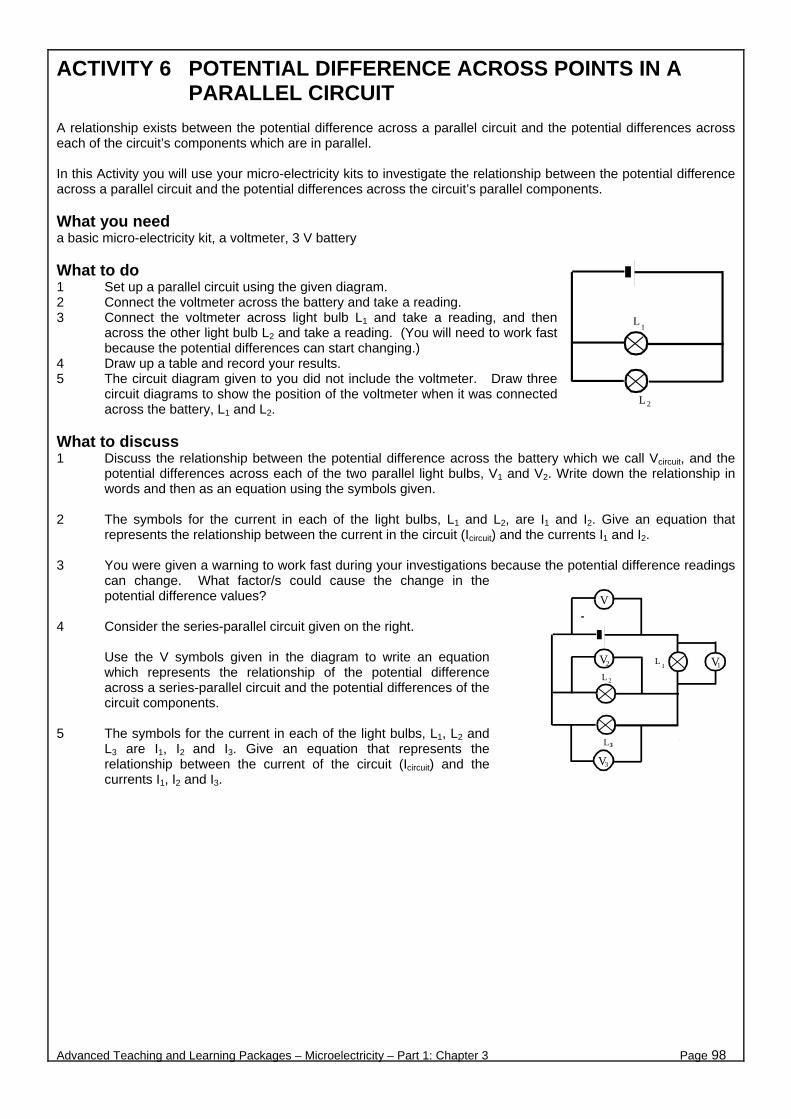
ACTIVITY 6 POTENTIAL DIFFERENCE ACROSS POINTS IN A PARALLEL CIRCUIT
A relationship exists between the potential difference across a parallel circuit and the potential differences across each of the circuit’s components which are in parallel. In this Activity you will use your micro-electricity kits to investigate the relationship between the potential difference across a parallel circuit and the potential differences across the circuit’s parallel components. What you need a basic micro-electricity kit, a voltmeter, 3 V battery What to do 1 Set up a parallel circuit using the given diagram. 2 Connect the voltmeter across the battery and take a reading. 3 Connect the voltmeter across light bulb L1 and take a reading, and then
across the other light bulb L2 and take a reading. (You will need to work fast because the potential differences can start changing.)
4 Draw up a table and record your results. 5 The circuit diagram given to you did not include the voltmeter. Draw three
circuit diagrams to show the position of the voltmeter when it was connected across the battery, L1 and L2.
What to discuss 1 Discuss the relationship between the potential difference across the battery which we call Vcircuit, and the
potential differences across each of the two parallel light bulbs, V1 and V2. Write down the relationship in words and then as an equation using the symbols given.
2 The symbols for the current in each of the light bulbs, L1 and L2, are I1 and I2. Give an equation that
represents the relationship between the current in the circuit (Icircuit) and the currents I1 and I2. 3 You were given a warning to work fast during your investigations because the potential difference readings
can change. What factor/s could cause the change in the potential difference values?
4 Consider the series-parallel circuit given on the right.
Use the V symbols given in the diagram to write an equation which represents the relationship of the potential difference across a series-parallel circuit and the potential differences of the circuit components.
5 The symbols for the current in each of the light bulbs, L1, L2 and
L3 are I1, I2 and I3. Give an equation that represents the relationship between the current of the circuit (Icircuit) and the currents I1, I2 and I3.
Advanced Teaching and Learning Packages – Microelectricity – Part 1: Chapter 3 Page 98
L2
L1
V
VL 2
L1
V
V
L3
12
3

HOMEWORK Here are some multiple choice questions which come from old matric exam papers. Choose a correct answer and then explain why you chose that answer. 1 The internal resistance of the source of emf in the following circuit is negligible:
V1 V2
A decrease decrease
B increase decrease
C decrease increase
D no change no change
2 Two identical light bulbs, P and Q, are connected in series to a battery of negligible internal resistance. V1 and V2 are identical voltmeters. If bulb P blows (because the filament breaks), how will the readings on V1 and V2 respectively change?
V1 V2
A increases becomes zero
B becomes zero increases
C becomes zero becomes zero
D remains the same
remains the same
3 In the circuit shown, the internal resistance of the battery is negligible. What will be the effect on the
voltmeter reading (V) and on the ammeter reading (A), if switch S is closed?
V A
A increases increases
B increases stays the same
C stays the same increases
D stays the same stays the same
Advanced Teaching and Learning Packages – Microelectricity – Part 1: Chapter 3 Page 99
V2V1
S
V V1 2
P Q
VA
S
R R1 2

ACTIVITY 7 - OHM’S LAW Many years ago a famous German physicist, Georg Simon Ohm (1787-1854), discovered the relationship between the current in a wire and the potential difference across the ends of the wire. When this relationship is expressed as a ratio, the ratio value is always the same. Because the ratio is constant it can be written as an equation. This constant is equal to the resistance (R) of the wire. This is known as Ohm’s law. To discuss before you start Work with the other members of your group to discuss the following: 1 How are we changing the current in this circuit? 2 Across which points is the potential difference being
measured? 3 Ohm’s Law applies to a given conductor only when the
temperature of the conductor remains constant. How can we keep the temperature of the resistor constant? Is it in fact necessary? Explain.
4 In this Activity, which is the independent variable, the current or the potential difference? Explain.
5 Plan a table in which to record your readings. What you need: a basic micro-electricity kit and2 multimeters. What to do 1 Set up the circuit using the micro-electricity kit as shown in the diagram.. 2 Join W to the positive terminal of your battery. 3 Join the negative terminal of the battery to the ammeter at V. 4 Move the free lead on the ammeter from X to Y to Z in turn. Read the potential difference across RA and
the current in RA each time.
5 Plot a graph which you can use to find the resistance (in ohms) of RA between W and X on the graph paper supplied.
6 Use the coloured bands on RA and the guidelines and the table next page to work out the resistance of RA. How does this compare with the resistance you measured from your graph?
7 Use the multimeter as an ohmmeter to measure the resistance of RA. How does this confirm with the
resistance you measured from the graph?
Advanced Teaching and Learning Packages – Microelectricity – Part 1: Chapter 3 Page 100
potential difference current
R = V I
resistance = potential difference current

HOW TO USE THE COLOURS ON YOUR RESISTOR TO WORK OUT ITS RESISTANCE (IN OHMS) Your resistor is likely to show FOUR bands which may or may not be of different colours. The first three bands tell you what the resistance of your resistor is in ohms. The fourth band tells you how accurate this resistance is. The GOLD or SILVER band tells us the accuracy to which the resistor was made. If the resistor has a gold band, the accuracy is 5%. If the resistor has (according to the colours on the first three bands) a resistance of 20 Σ, then, its resistance will vary from 19 Σ, to 21 Σ,. If the resistor’s colour code tells us that it has a resistance of 20 Σ with a silver band, its resistance will be in the range from 18 Σ to 22 Σ. The table below shows the numerical values for each of the colours.
0 black 5 green
1 brown 6 blue
2 red 7 violet
3 orange 8 grey
4 yellow 9 white
The colour of the FIRST band gives you a number which you can read from the table. The colour of the SECOND band gives you a colour which you can read from the table. The colour of the THIRD band tells you how many zeros (0's) there are after the first two numbers. Use the table to work out the resistance (in ohms) of the resistor in the diagram above. (It is 27 000 Σ.)
Advanced Teaching and Learning Packages – Microelectricity – Part 1: Chapter 3 Page 101
This is the FOURTH BAND.It is either silver or gold. Gold tells us that the accuracy is 5%.Silver tells us that the accuracy is 10 %
violet - the SECOND band
orange - the THIRD band
red - the FIRST band
Advanced Teaching and Learning Packages – Microelectricity – Part 1: Chapter 3 Page 102
B. THE MAGNETIC EFFECT OF AN
ELECTRIC CURRENT

ACTIVITY 1 - PARALLELISMS Since a magnetic field exerts a force on a current carrying wire, and a current carrying wire produces a magnetic field, why shouldn’t a current carrying wire exert a force on another current carrying wire? Only too logical! (as Ampere first pointed out.) This is what you are going to investigate in this Activity. You might even come up with a formula!!!
What you need micro-electricity kit, steel-wool PREDICT 1 The diagram on the right, shows two parallel current carrying wires. Each
current produces a magnetic field.
a On the diagram indicate the direction of the magnetic field lines produced by current I1.
b Indicate the direction of the field at point A, located on the wire
number 2.
c Use the left hand rule (the FBI rule), to find the direction of the force on the wire number 2, at point A.
d How will wires number 1 and 2 behave?
2 Based on your answers in question 1, predict how the wires will behave, if the current in wire number 2 is in
the opposite direction. TEST YOUR PREDICTION Test your predictions using your micro-electricity equipment. Work as a group, and combine your components when necessary. 1 Set up the micro-electricity equipment, as shown in Diagram 1. Pull two long strands from the steel-wool. If
possible, choose thick strands (the strands in the steel-wool have different thicknesses!) Connect the two strands between springs A and B. The strands must not touch each other, but they must be as close to each other as possible.
The steel-wool strands are your parallel current carrying conductors. a In which spring must you connect the black wire from the cells, so that the current in both steel-wool wires is in the same direction? Explain and indicate the direction of the current in diagram 1. b Complete the circuit in diagram 1, for no more than a second (by touching the correct spring). Look carefully at the steel-wool wires. Repeat if necessary. c Why must you complete the circuit for only a short time? Explain.
Advanced Teaching and Learning Packages – Microelectricity – Part 1: Chapter 3 Page 103
I1 I2
wire No 1 wire No 2
A
A B
Steel-wool
DIAGRAM 1

2 Change the set up of your equipment as in Diagram 2 alongside. Take the top strand of steel-wool and connect it between springs B and C. Once again, the strands must not touch each other, but they must be as close to each other as possible (connect them to the inner sides of the springs A and C).
a In which spring must you
connect the black wire from the cells, so that the current in the steel-wool wires is in the opposite direction? Explain and indicate the direction of the current in each wire, in Diagram 2.
b Complete the circuit in Diagram
2, for no more than a second. Look carefully at the steel-wool wires. Repeat if necessary.
3 Discuss your observations with your group. In each case, what happens to the two parallel current carrying
wires and why?
4 Discuss factors which you think would affect the force between two parallel current carrying wires. Explain how these factors would affect this force. Can you describe the relationship between these factors and put them in a mathematical form? When possible, test the effect of these related factors with your equipment.
5 Prepare a group report. In your report, explain what you did, what you discovered, your explanations and
comments for further investigations. EXTENSION QUESTION 6 The diagram on the right, shows two parallel current carrying wires.
Both currents are in the same direction. Current I1 is much larger than current I2. Draw the forces exerted on both wires. Compare these forces and explain whether these forces should be equal or unequal.
Advanced Teaching and Learning Packages – Microelectricity – Part 1: Chapter 3 Page 104
A B
Steel-wool
DIAGRAM 2
C
I1 I2
wire No 1 wire No 2