advanced internal cooling geometries double wall …€¢ work should directly impact materials...
TRANSCRIPT

Advanced Internal Cooling Geometries Double Wall SchemesGeometries ‐ Double Wall Schemes With and Without Effect of Rotation
Srinath V. Ekkad
Associate ProfessorAssociate Professor
Mechanical Engineering
Virginia Techg
Collaborators: Dr. Diganta Narzary, Justin Lamont, Preston Stoakes, and Dr. Mary Anne Alvin (NETL)

Programmatic Relevanceg• IGCC plants play a key role in the future of DOE’s Clean coal
initiative by facilitating pre‐combustion CO2 capture from syngas
• Gas turbines used in IGCC are subjected to high thermal loads and high temperatures along with residual particulate and vapor contaminants which could potentially alter the life of precision engineered vanes and blades in the hot gas path
• The proposed research aims to develop physics based modeling tools to develop and predict new cooling strategies for hot components and provide effective cooling h ith l l t ith di t i tschemes with low coolant usage with direct impact on
overall efficiency• Work should directly impact materials development and
i lcoatings also
Why Double Wall Cooling?Why Double Wall Cooling?• Double wall cooling uses a thin gap between two g g pwalls to enhance heat transfer from the surface of turbine blades
• Double wall cooling increases area for heat transfer between cooling fluid and metal
• Impingement jets and modified surfaces can be used to increase heat transfer on the outer wall
• Nothing new about this concept – has been around for several decades

Patents on Double Wall coolingPatents on Double Wall cooling
Patents by Bunker et al., Ishburg and Lee, Jackson et al., Liang, Melvin et al.

Other cooling options including double wall
• Network of orifices connected
g p g
by small passages to create impingement areas and outward film coolingoutward film cooling
• Cool air is force into double wall area through small
d hpassages and impinges on the outer wall
• Lamilloy© is a standardLamilloy© is a standard practice used By RR in North America (mature technology)

Another Existing DesignAnother Existing Design
• System of pedestals andSystem of pedestals and ribs used to increase turbulence and heat transfer
• Cooling gas exhausted through trailing edge of blade
d• Design does not use impingement cooling
Liang G, inventor; 2004 Oct. 26. Cooling system for a turbine blade having a double outer wall. United States Patent US 6,808,367.US 6,808,367.

Motivation & Objectives• Gas turbine blades need to be effectively cooled to increase
component life and reduce maintenance costs. The level of cooling is always off‐set by the amount of coolant used. Increased amount of coolant usage directly impacts the overall ffi i f th iefficiency of the engine.
• Usage of double wall cooling schemes can reduce overall coolant usage by pushing coolant closer to the inside of the wall exposed to hot gas path. Th h d h t t f t th l t th h th thi ll• The enhanced heat transfer to the coolant through the thin wall and also due to high performance schemes such as impingement will greatly benefit overall and thermal efficiency of the system.
• The focus is:• The focus is:– to develop an optimization methodology to determine the
most effective double wall/near wall scheme for turbine airfoil cooling. These cooling geometries will be optimized for the highest heat transfer enhancement with lowfor the highest heat transfer enhancement with low pressure drop with optimization software and CFD.
– to study the effect of rotation on double wall cooling geometries to ensure applicability to rotating blades
– to study the performance of the optimized geometry
Typical turbine blade internal convection cooling configuration (Han et. al. (1986).to study the performance of the optimized geometry
working with OEMs to compare cooling effectiveness of double wall geometries compared to current cooling schemes

Project SummaryProject Summary• Objective:
– Explore the use of double wall cooling in turbine blades, using p g gimpingement cooling and combining with other standard heat transfer enhancement techniques
– Develop design methodologies for optimized double wall cooling designs for industry usagecooling designs for industry usage
• Procedure:– Use CFD to explore the effectiveness of impingement cooling in
channel flowchannel flow– Use CFD to optimize design pattern of impingement holes in
channel flow– Experimentally determine performance of optimized– Experimentally determine performance of optimized
configuration in comparison to current standard designs– Also experimentally study effect of rotation on double wall
cooling designs with intention to optimize with rotational effectsg g p

Stationary Optimization Study
St t ith Si lifi d G tStart with a Simplified Geometry• The simplified geometry consists of mainThe simplified geometry consists of main channel with an impingement channel connected by an array of impingement jetsconnected by an array of impingement jets
• Main channel measures 1” x 1” for all test sectionssections
• Impingement channel dimensions and length f i i b hof test section varies between the cases

GeometryGeometry
• Impingement jet array isImpingement jet array is 2 x N, N varies in the optimization study
• Impingement channel confines the spent coolant to exit opening opposite inlet

ProcedureProcedure
• Optimize geometry using Computational FluidOptimize geometry using Computational Fluid Dynamics (CFD)– Independent parameters chosen based on studies– Independent parameters chosen based on studies found in literature
• Top designs from CFD optimization will be• Top designs from CFD optimization will be built for experiments
Test sections constructed from aluminum to– Test sections constructed from aluminum to include conduction effects
OptimizationOptimization
• Four parameters varied to determine effect ofFour parameters varied to determine effect of each on heat transfer and pumping power– Hole Diameter (D)– Hole Diameter (D)
– Jet‐to‐Jet Spacing Ratio (L/D)
Jet to Wall Spacing Ratio (H/D)– Jet‐to‐Wall Spacing Ratio (H/D)
– Number of rows of holes (N)
Ai fl i d i h N d D i i• Air flow rate varied with N and D to maintain a jet Reynolds Number of 10,000

OptimizationOptimization
• A total of 256 testA total of 256 test section designs were considered by choosing
Range
Parameter Min Maxfour design points for each parameter
Parameter Min Max
D1/32” 1/4”
(0.794 mm) (6.35 mm)
• Total length, LT, held constant when N is varied
L/D 2 5
H/D 0.5 4
N 5 11varied
in1/11 DLDLTT

OptimizationOptimization
• Test section designs ranked based on heatTest section designs ranked based on heat transfer coefficient along the impingement surface h and pumping power for fluid PPsurface, h, and pumping power for fluid, PP
• The two parameters are combined to form a performance Per parameter to easilyperformance, Per, parameter to easily compare the test section designs
hh
0,
0
PP PPhhPer
• All test sections compared to baseline design

ResultsResults
• Number of rows of holes N and Jet‐to‐WallNumber of rows of holes, N, and Jet to Wall spacing ratio, H/D, appear to have the largest affect on the performance parameteraffect on the performance parameter
• Jet‐to‐Jet spacing ratio, L/D, appears to have very little affect on the performancevery little affect on the performance parameter
Th 10 f i d i b il• The top 10 performing designs were built to validate CFD study

ResultsResults
Rank D (in) L/D H/D N Per
1 0.125 5 2 5 51.7
2 0.125 2 1 5 51.6
3 0 125 4 2 5 51 43 0.125 4 2 5 51.4
4 0.0625 2 1 5 50.2
5 0.25 2 2 5 50.2
6 0.125 2 2 5 49.9
7 0.25 3 2 5 49.3
8 0.125 3 2 5 48.9
9 0.0625 4 1 5 48.9
10 0.0625 3 1 5 48.8

Results for best designResults for best design
• Velocity contours showVelocity contours show higher velocity through last row of holes– Final jet is deflected by cross flow of exhaust gas
h l b
Contours of velocity at plane intersecting impingement jets
• Highest Nusselt number values occur under impingement jetsimpingement jets– Exhaust gas appears to exit in two streams inline
Contours of Nusselt Number on impingement surface
with impingement jets

Future WorkFuture Work• Experiments are being conducted to validate CFD simulations on initial test section
• Turbulators can be added to the impingement p gchannel to disrupt flow of exhaust gases– The flow disruption should allow for a more even pheat transfer distribution, as well as reduce jet deflection due to cross flow
– Pin fin turbulators will increase amount of conduction into the main channel and further i f i h fincrease area for convective heat transfer

Multiple Array Impingement for Low H/d double wallMultiple Array Impingement for Low H/d double wall cases
• Study effect of exhaustStudy effect of exhaust gas cross flow when jet‐to‐wall spacing ratio is below 1
• Initial CFD study base on jet‐to‐jet spacing ratio
d l d• Compared inline and staggered arrangement of jetsof jets
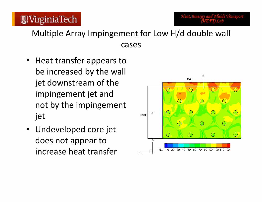
Multiple Array Impingement for Low H/d double wall p y p g /cases
• Heat transfer appears toHeat transfer appears to be increased by the wall jet downstream of the impingement jet and not by the impingement j tjet
• Undeveloped core jet does not appear todoes not appear to increase heat transfer

Multiple Array Impingement for Low H/d double wall cases
• Staggered arrangement 2Staggered arrangement of jets performed better at all jet‐to‐jet spacing 1.6
1.8
meter
ratios
• Higher jet‐to‐jet spacing 1.2
1.4
ance Param
ratio appears to increase performance of design 0 8
1
1.2
Performa
of design
• Future study will explore larger jet to jet
0.6
0.8
1.5 2.5 3.5 4.5
Staggered Inline
explore larger jet‐to‐jet spacing ratios
L/D

Rotational EffectsRotational Effects

A simplified geometry was tested to determine the effects of rotation on blade internal coolant channel flow
A typical coolant passage from turbine blade is modeled in this experiment with simple square
Leading Side (Suction)
experiment with simple square geometry.
Trailing Side (Pressure)
Typical turbine blade internal convection cooling configuration (Han et. al. (1986).

The rotating rig spins interchangeable test sections at desired speeds while low temperature air is injected
• Nitrogen Gas is vented into the air path before testing to chill components. This drops the temperature of the air before reaching the test section during a test.
• A camera is mounted to the test section to view the color change of the liquid crystals. One side is filmed at a time,change of the liquid crystals. One side is filmed at a time, so the motor rotation direction is reversed when filming either the leading or trailing side.

The effect of rib type in rotational two‐pass channels was explored using a transient liquid crystal technique
• Smooth wall, 90° Ribbed, and W‐shape ribbed walls were explored in the study.
• Each case was held at a • Re = 16 000 and a rotational speed
Smooth Wall
• Re = 16,000 and a rotational speed of 250 rpm
• (Rotation number=0.08). • Inlet density ratio = 0.10
90° Ribs
• Results are reported for the trailing side, leading Side, and stationary The sides are
W-shape Ribs
stationary. The sides are compared to the stationary case.
45°Pitch-to-rib height ratio (P/e)=8Blockage ratio (H/e) = 8Blockage ratio (H/e) 8
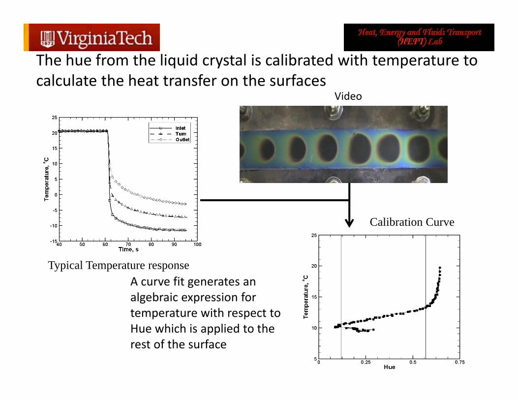
The hue from the liquid crystal is calibrated with temperature to calculate the heat transfer on the surfaces
Video
Calibration Curve
Typical Temperature response
Calibration Curve
A curve fit generates an algebraic expression for temperature with respect to H hi h i li d t thHue which is applied to the rest of the surface

A semi‐infinite model is used to determine the local
A transient liquid crystal technique is used to determine the heat transfer. For the given test section, the semi‐infinite solid model is valid if the experiment times does not exceed
convective heat transfer on the channel walls
g p25 minutes. Average test time is less than a minute. After calibrating the liquid crystal hue with temperature, wall temperatures for each pixel at each frame in the video is calculated.
Temperature is calculated at the surface (x=0) so the mathematical model used reduces to:
therfcthTtT i 2exp1),0(
k
erfckTT i
2exp1
T : is the averaged bulk temperature from the inlet and outletT∞ : is the averaged bulk temperature from the inlet and outletTi : is the initial wall temperatureT(0,t): is the wall temperatureα: is the thermal diffusivity of the acrylict: is the timet: is the time
We know all parameters, so we are able to solve for h numerically

The liquid crystal creates a continuous plot of heat transfer on q y pthe surface of the coolant channel
Smooth Wall 90° ribbed Wall W‐shape ribbed Wall
StationaryLeading Trailing
Nu / Nu∞
StationaryLeading Trailing
Nu / Nu∞
StationaryLeading Trailing
Nu / Nu∞
Smooth Wall 90 ribbed Wall W shape ribbed Wall
StationaryLeading Trailing StationaryLeading Trailing StationaryLeading Trailing
The W‐ribs create the highest heat transfer in the channel. The smooth wall channel has the lowest heat transfer.
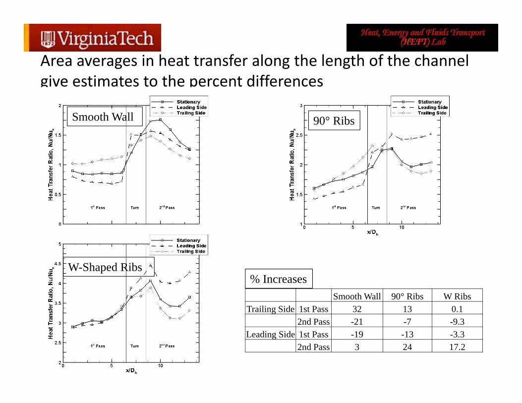
Area averages in heat transfer along the length of the channel give estimates to the percent differences
Smooth Wall 90° Ribs
% IncreasesW-Shaped Ribs
Smooth Wall 90° Ribs W RibsTrailing Side 1st Pass 32 13 0.1
2nd Pass -21 -7 -9.3
% Increases
Leading Side 1st Pass -19 -13 -3.32nd Pass 3 24 17.2

The rib types are directly compared for the stationary, trailing side, and leading sideyp y p y g g
Stationary Trailing Side
Leading SideStationary Trailing Side Leading Side
% IncreasesStationary Trailing Side Leading Side
1st Pass 90° Ribs 104 71 116W-Ribs 260 190 325
2nd Pass 90° Ribs 35 55 76W-Ribs 138 164 197

Jet Impingement cooling is an alternative to rib roughened walls to create high heat transfer
• Instead of a two pass channel, a radially outward channel with
Leading Side (Suction)
yimpingement is studied under rotation
• Current results show impingement
Trailing Side (Pressure)
p gchannel height‐to‐jet diameter ratio (H/d) = 2
• Pitch‐to‐jet diameter ratio
Typical turbine blade internal convection cooling configuration (Han et. al. (1986).
• (P/d) = 8
• Jet length‐to‐jet diameter ratio • (b/d)= 1
• Rotational speed =250 rpm

Preliminary stationary results for jet impingement cooling with crossflow effect
• Flow moves from right to left. There is one outlet for the air, so the later jets f l h ff ffeel the effects of crossflow.
• Crossflow bends the jets away from the wallaway from the wall, reducing the effectiveness.
• The effects of crossfloware present in the resultsare present in the results, as the average heat transfer reduces and the maximum heat transfer for each jet reduces as we get closer to the exit.

Preliminary rotational results for trailing and leading sides with crossflow effect
• In rotation, both the leading and trailing side results are less than the stationary results (this is expected due to previous studies by Parsons and Han (1998)(this is expected due to previous studies by Parsons and Han (1998).
• Also, the trailing side reduced more than the leading side. This is counter intuitive because radially outward flow for two‐pass channels show an increase in heat transfer for the trailing side due to the favorable effects of the Coriolis force.

Future studies on rib roughened and jet impingement cooling schemes under rotation
Rib Roughened Walls Jet Impingement
• Further explore the W-shaped Ribs with variations on flow orientation of ribs and angle of ribs
• Explore rotational effects when the impingement height is varied (H/d), when pitch is varied (P/d), effect of film coolant extraction vs. crossflowexit conditions, and Jet angle with respect to the impingement plate is varied.
Vs. • Capabilities of the Rotating Rig are in the process of being increased. Higher flow rates, lower temperatures and higher rotational speeds will be achievable.

ConclusionsConclusions• First year of project• Understanding various parametric effects on double wall cooling schemes
• Developed a new test rig for detailed measurements in• Developed a new test rig for detailed measurements in rotating frame for internal heat transfer
• Fundamental methodology of optimization achievedgy p• Focusing on more realistic geometries from here on• Working with industry to determine factors of evaluation and design methodology for new cooling geometries