advanced imaging for non-destructive control of pressure ... · advanced imaging for...
TRANSCRIPT
Advanced imaging for non-destructive control of pressure vessels
Henri WALASZEK
Pôle Equipement sous Pression et Ingénierie de l’Instrumentation (EPI)
33 344673324
www.cetim.fr [email protected]
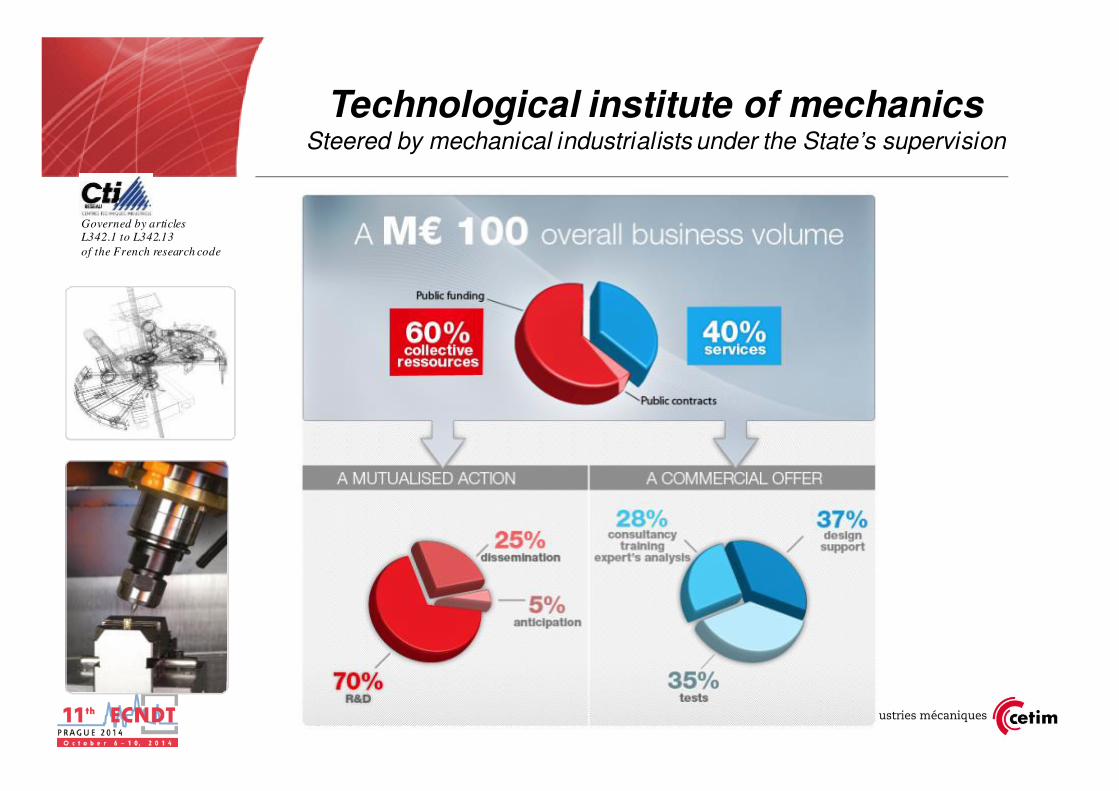
Governed by articles L342.1 to L342.13
of the French research code
Technological institute of mechanicsSteered by mechanical industrialists under the State’s supervision
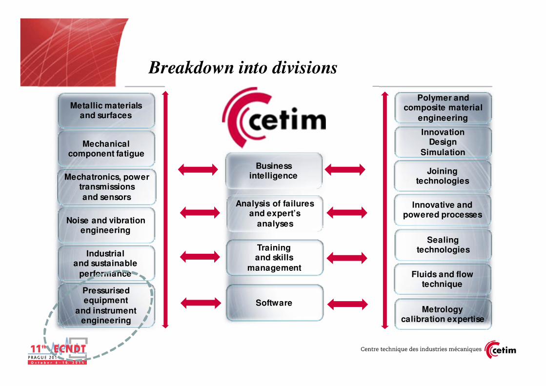
Industrialand sustainable
performance
Metallic materialsand surfaces
Noise and vibration engineering
Mechatronics, power transmissions
and sensors
Pressurisedequipment
and instrument engineering
Mechanicalcomponent fatigue
Analysis of failuresand expert’s
analyses
Training and skills
management
Software
Sealingtechnologies
Innovative and powered processes
Polymer and composite material
engineering
Fluids and flow technique
InnovationDesign
Simulation
Joiningtechnologies
Metrologycalibration expertise
Businessintelligence
Breakdown into divisions

Page 4
Applied research and services in NDTCETIM offer
o Detection of defects in metal and composites : welds, cracks, porosities, thickness, delamination..
o Caracterization of materials : grade, stresses (residual, pre-load), thermal and thermochemical treatments
o Qualification / requalification of pressure equipments (AT, UT…)
oAcoustic emission monitoring (defects, leaks…)
oSimulation of NDT with CIVA software
• Feasibility studies,
• Improvement of existing NDT solutions
• Development of new solutions
• Expertise, NDT services

Page 5Page 5
Some « traditional » NDT have limitations
Visual :•Lack of traceability•Dependance of operator
MPI, Dye penetrant:•Lack of traceability•Dependance of operator
•Use of polluants•Automatisation difficult
•Time of operation
X-ray testing:
•Ionizing radiation
exposure
•Time of operation
Conventional UT :•Lack of traceability•Local response
•Interpretation

� Thanks to technological evolutions
� Digital and data processing techniques are more powerfull
� Transposal of medical and military technology
� These technologies are implemented in NDT equipment and affordable
� Many NDT equipment integrate image display and processing
� Enable global view of the component being inspected
� Make easier result interpretation
� Traceability and data storage are enhanced
� Communication about NDT results is improved
� Simulation softwares are available and help to save time and efficiency
� Signal processing applications
Technological context
11/2012

Page 7Page 7
28 octobre 2009 – ITT09
Tofd ultrasonics as alternative to X-ray testing
Wall
thickn
ess
trans
mitte
r
rece
iver
1
2 2
12
3 4
3
4
TOFD Image
X-ray Image
Standardised method
Page 8
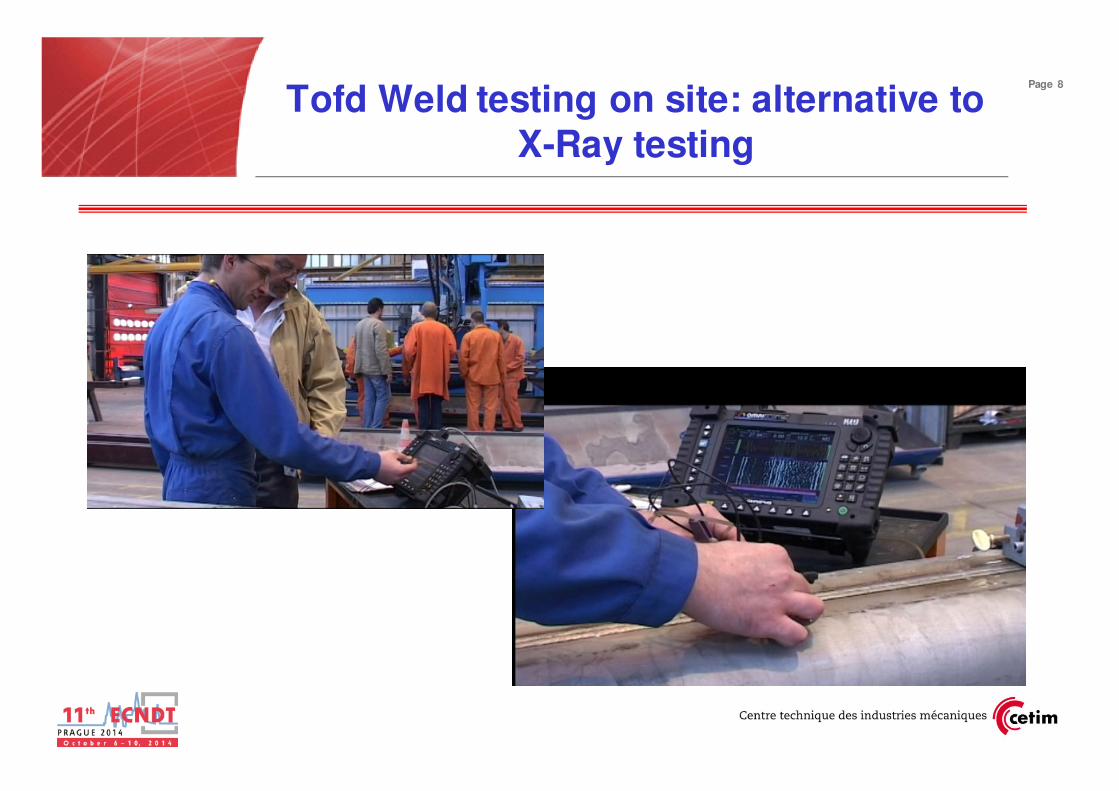
Tofd Weld testing on site: alternative to X-Ray testing
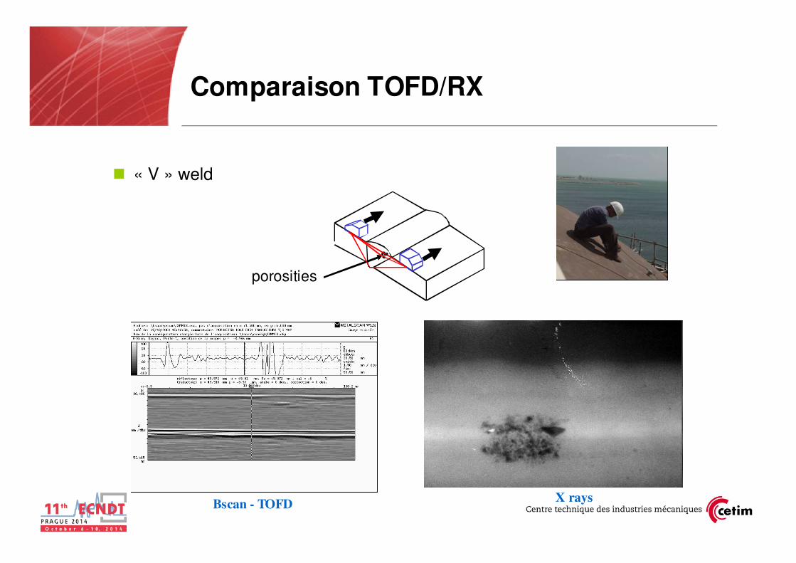
Comparaison TOFD/RX
� « V » weld
X rays
porosities
Bscan - TOFD

Page 10Page 10
28 octobre 2009 – ITT09
Tofd ultrasonics for fatigue crack growth imaging
Application to a transmission
shaft

11/2012
TOFD Corrosion assesment on Trans-Channel tunnel
pitting
Receiving probe
Transmitting probe
Incident beam Diffracted beam
Conventional ultrasonic probe
No reflection

11/2012
TOFD Corrosion assesment on Trans-Channel tunnel
� Advantages: quick imaging,
� traceability, portability
� Limitations: same as in conventional UT, size of the probe

� Advantages of TOFD ultrasonic technique� Fast mapping of the corrosion� Unsensitive to orientation of corroded area
� Reduce of time for inspection� Global view of the corrosion
� Large surface inspected
� Limits the risk of missing the maximum corrosion depth
� Limitations of TOFD ultrasonic technique� Data volume storage
� Skill of operators higher than with conventional UT
� Acoustic coupling, measurements difficult on rough surfaces
TOFD ultrasonics advantages
11/2012
Page 14Page 14
28 octobre 2009 – ITT09
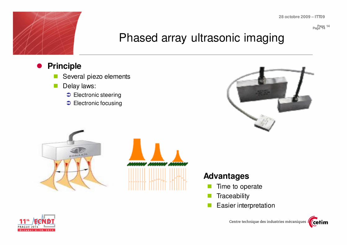
Phased array ultrasonic imaging
� Principle� Several piezo elements
� Delay laws:
� Electronic steering
� Electronic focusing
Advantages� Time to operate
� Traceability
� Easier interpretation

Page 15Page 15
28 octobre 2009 – ITT09
Xrays
Carbon steel
Thickness 35mm
Phased array ultrasonics as an alternative to X-rays

Page 16
Traditional thickness measurement on penstock pipe
Thickness measurement on site

Page 17
Now: thickness cartographies with PA
ultrasonic transducers
Phased array transducer on the pipe wall

Page 18
Phased array testing of cracks on shaft
� Shaft having length more than 1 meter and dia 180mm
� End acess only
� Potential cracks on filets
CIVA Simulation
Page 19
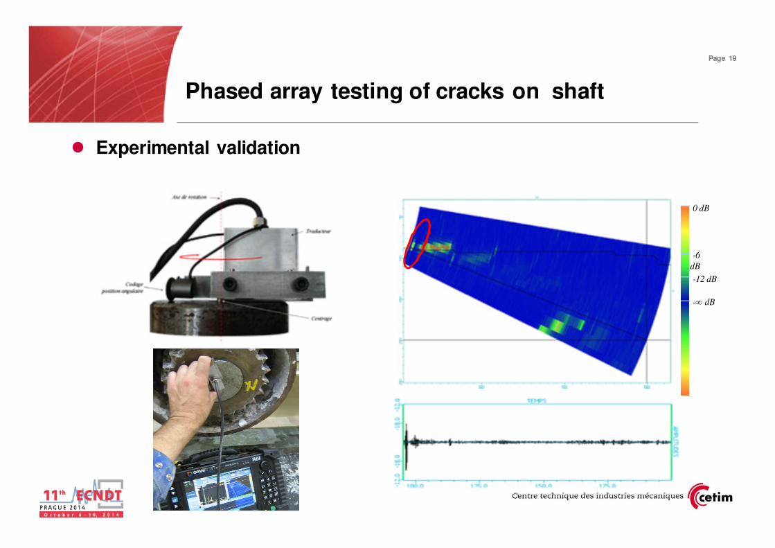
Phased array testing of cracks on shaft
� Experimental validation
0 dB
-∞ dB
-6
dB
-12 dB
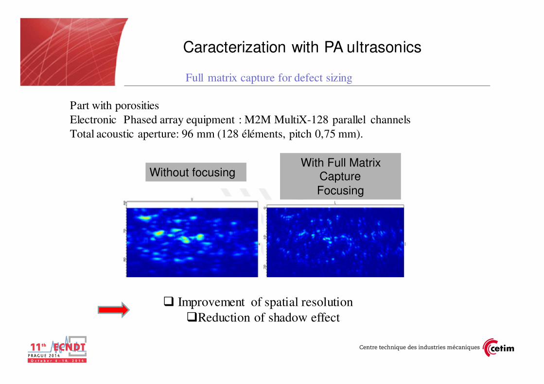
Part with porosities
Electronic Phased array equipment : M2M MultiX-128 parallel channels
Total acoustic aperture: 96 mm (128 éléments, pitch 0,75 mm).
Avec FMC
Full matrix capture for defect sizing
Caracterization with PA ultrasonics
Sans focalisation
� Improvement of spatial resolution
�Reduction of shadow effect
Without focusingWith Full Matrix
Capture
Focusing

Page 21
Transfer of studies on advanced ultrasonics:
� Training of operators on TOFD and Phased array
� Certification through COFREND
� Rédaction of guide CETIM / IS « alternativeà la radiographie iridium »

Applications on compositestructures
� 3D ultrasonic imaging
� Requirements
� Wide structure testing (tanks, double curvature panels,…)
� Alternative to tank immersion
� Prototype parts, limited series,…
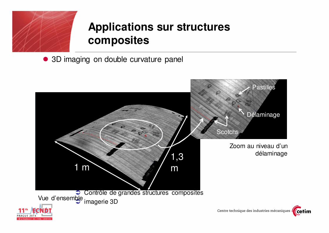
Applications sur structures composites
� 3D imaging on double curvature panel
� Contrôle de grandes structures composites
� imagerie 3D Vue d’ensemble
Zoom au niveau d’un délaminage
Pastilles
Scotchs
Délaminage
1 m1,3
m

Page 24
Ultrasonic waves
Halogen lamp
Flash lamps
Source
Active thermal infrared
Source:

Page 25Active thermal infrared on composite plates
� Testing of impact damaged composites
15J impact on opposite side/camera
Flash excitation on
camera side
Phase diagram

Other applications of active thermal
infrared on metallic materials
� Testing of welds (flaws open to the surface)
28 mm
18 mm
5 mm22 mm
Magnetic particle testing
Infrared thermography (induction)
Page 26

Page 27
� Drawbacks of active infrared thermography� Inspection depth is limited according to thermal diffusivity of the material
� A few millimeters for monolithic material, more for honeycomb
� Surface properties affect the inspection
� Interpretation of data requires knowledge of thermal behaviour of the material
� Advantages of active infrared thermography� Global, non intrusive, contact-less and eco-friendly inspection
� In some cases, IT could replace Penetrant Testing for example
� Applicable to many material and kind of defects� Composite, metallic� Delamination, disbonding, crack, water infiltration, …
� Wide range of excitation sources� Feasibility study is required to choose the best one
� Allows to determine the shape and the depth of the defect� Temporal or frequency analysis
Active infrared thermography
Page 28
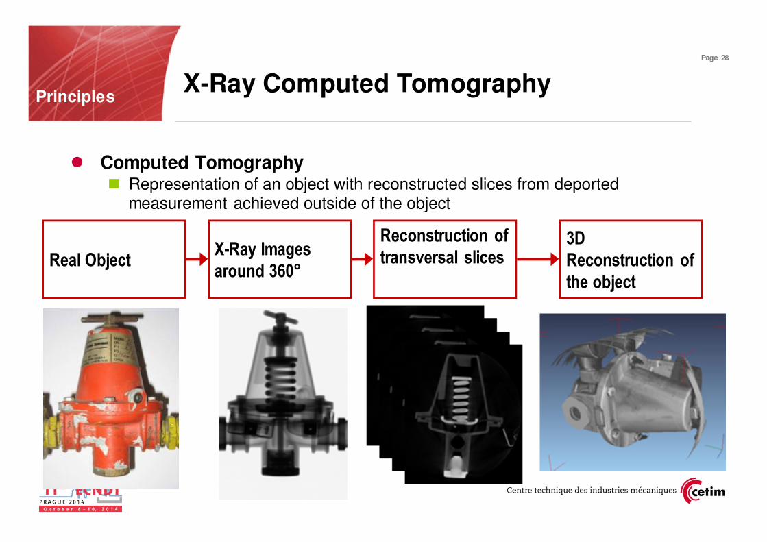
X-Ray Computed TomographyPrinciples
Real ObjectX-Ray Images
around 360°
Reconstruction of
transversal slices3D
Reconstruction of
the object
� Computed Tomography � Representation of an object with reconstructed slices from deported
measurement achieved outside of the object

Page 29
Computed tomographyEquipment characteristics
Medical applications
Type Nanofocus CT system
Microfocus CT system
Macrofocus CT systemMedical CT
systemCharacteristics
Energy max 180 keV 240 keV 150 to 600 keV 1 to 15 MeV 160 keV
Dmax object 120mm 200mm 1m >> 1m 1m
Resolution 0,5 to 10µm 1 to 50µm 0,1 to 0,5mm 0,5 to 1mm 0,1 to 0,5mm
Cost 250 – 500 k€ 250 – 500 k€ 250 – 800 M€ 0,8 – 1,5 M€* 1 – 3M€
NDT applications
Courtesy of VJ Technologies
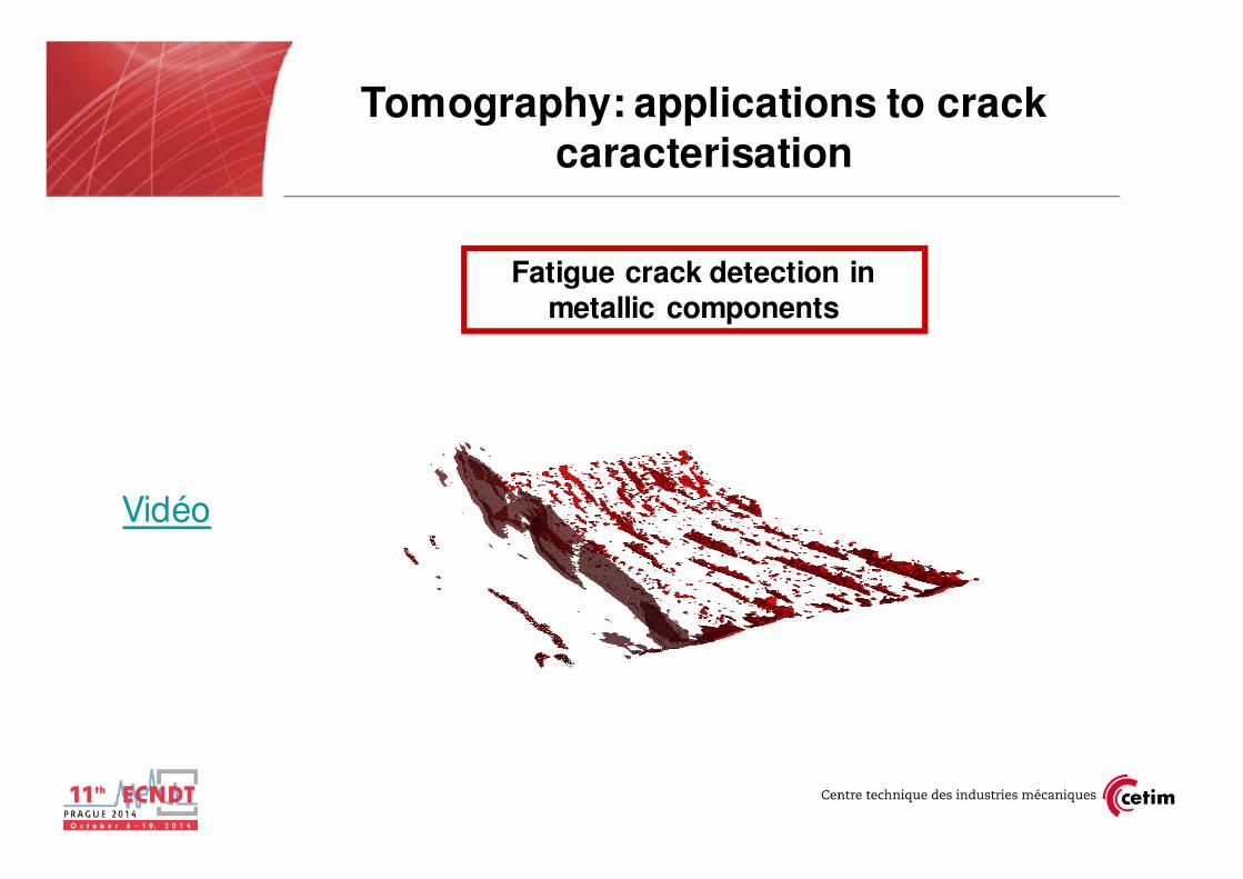
Tomography: applications to crack caracterisation
Fatigue crack detection in metallic components
Vidéo
Page 31
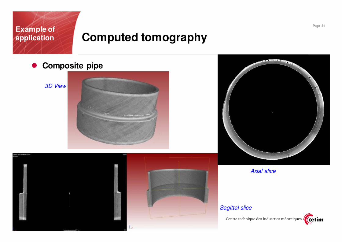
Computed tomographyExample of application
� Composite pipe
Sagittal slice
Axial slice
3D View

Page 32
� Drawbacks of X-ray Computed Tomography� Non-portable system� Final resolution depending on the object size
� Acquisition and reconstruction duration (from 0,25 to 12h)� Amount of data to analyse (from 2 to 20Go)
� Advantages of X-ray Computed Tomography� Non-sensitive to the defect orientation and material
� 3D defect reconstruction and location in the volume� Complex shape inspection
� Comparison with CAD or others scans
� Dimensional measurement
� R&D applications, expertise, retro-engineering
Computed Tomography

Page 33
Application of NDT methods to detection and sizing of delamination in an impact damaged
part
Testing of impact-damagedcomposite plates

Page 34
�In aircraft industry
� Many structural composite parts are dimensioned through impact tests
– Impact tests trials on standardized parts
� CETIM equipment: Impact machine dedicated to these tests
– Trials meeting standard AITM 1-0010 requirements
Testing of impact-damaged composite plates
Impact machine
available in CETIM
L = 150mm
l =
10
0m
m
Monolythic epoxyde resin –carbon fiber
Unidirectionals plies oriented 0°,+/- 45° or
90°
Total thickness 3,0mm

Page 35Testing of impact-damagedcomposite plates
NDT means
used
Thermal camera
Flash location for front side excitation
Flash location for back side
excitation
Sample under test
20cm 50cm
Active thermal infrared with flash excitation
X ray computed Tomograph
(CETIM/MONTUPET project Tomopic)
• Thermal infrared
• Computed X ray tomography

Page 36
� delamination signature evolution versus depth in the part
30J
Sample test
Impacted side Opposite side /impact
Testing of impact-damaged composite plates
X r
ay
com
pute
d
tom
ogra
phy
Act
ive
ther
mal
infr
are
d*
*- phase at different frequencies , front face flash

Page 37
� Non Destructive Inspection using imaging technique have many advantages� Global eyesight of the inspected component
� Easier interpretation � Improvement of traceability and storage of the data� Facilitates the communication between NDT provider and customer
� Imaging techniques may sometime represent an “clean” alternative to traditional
techniques� Ultrasonic TOFD and Phased array imaging /X-ray testing (Standardization?)� Increase of the sensitivity/conventional UT� Next future: imaging improvement with matrix transducers� In the future: Thermal infrared-metallic component /MPI and Dye penetrant?
� The signal processing is now integrated in advanced equipment (Saul/M2M…..)
� Ultrasonic inspection would benefit of the simulation:� Optimization of the part at conception stage
� Reduction of the need of prototype parts� 3D computed Tomography - internal view of the component
Conclusions & Perspectives

Page 38
Thank you for your attention
Do you have some questions?