advanced high strength steel application guidelines/media/files/autosteel/great designs in...
TRANSCRIPT

w w w . a u t o s t e e l . o r g
Advanced High Strength Steel Application Guidelines
Blake K. ZuidemaArcelor Mittal - USA Research & Development
w w w . a u t o s t e e l . o r g
PRESENTATION OVERVIEW
• History and purpose of this A/SP project• Summary of key results to date• Future Plans• Directions for obtaining current and future
results from the A/SP public website

w w w . a u t o s t e e l . o r g
HISTORY AND PURPOSE
Practical guidelines for forming AHSScomponents remain a key enabling technology:
• Product design guidelines to assure manufacturability• Selection of optimum stamping processes• Resolving formability issues• Controlling springback• Selecting die materials for optimum tool robustness

w w w . a u t o s t e e l . o r g
HISTORY AND PURPOSE
Several programs seek longer-term solutions:
• USAMP AMD 311 – Springback Compensation Project for Advanced Sheet Forming Materials
• USAMP AMD406 – Die Face Engineering for Advanced Sheet Forming Materials
• A/SP HSS Stamping Project
…..but interim solutions are needed today!

w w w . a u t o s t e e l . o r g
HISTORY AND PURPOSE
A/SP AHSS Applications Guidelines Project:• Initiated in 2005• Compiling case studies of AHSS components• Extracting lessons learned on:
– Part design for stamping feasibility– Suitability of chosen forming process– Managing springback– Dealing with die wear and robustness
w w w . a u t o s t e e l . o r g
PROJECT TEAM MEMBERS
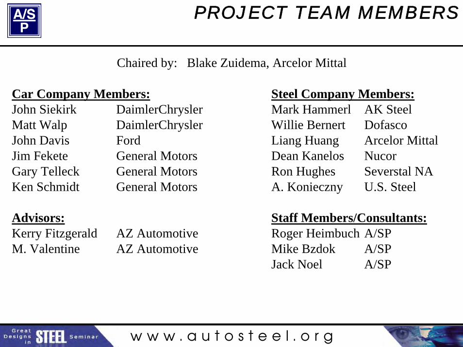
Chaired by: Blake Zuidema, Arcelor Mittal
Car Company Members:John Siekirk DaimlerChryslerMatt Walp DaimlerChryslerJohn Davis FordJim Fekete General MotorsGary Telleck General MotorsKen Schmidt General Motors
Advisors:Kerry Fitzgerald AZ AutomotiveM. Valentine AZ Automotive
Steel Company Members:Mark Hammerl AK SteelWillie Bernert DofascoLiang Huang Arcelor MittalDean Kanelos NucorRon Hughes Severstal NAA. Konieczny U.S. Steel
Staff Members/Consultants:Roger Heimbuch A/SPMike Bzdok A/SPJack Noel A/SP

w w w . a u t o s t e e l . o r g
KEY RESULTS
Elements Selected for Case Study Database• Part description
• Material description
• Press line constraints
• Stamping process design – process flow block diagram
• Detailed description of each die stage
• FEA formability analysis results
• Negotiated geometry concessions

w w w . a u t o s t e e l . o r g
KEY RESULTS
Elements Selected for Case Study Database• Springback compensation methodology
• Springback control history
• Springback model results and accuracy
• Press load predictions and press load prediction accuracy
• Final springback control measures
• Tolerancing requirements
• Fixturing and clamping methods
• Post-launch experience
• Lessons learned

w w w . a u t o s t e e l . o r g
KEY RESULTS
Current Case Study Library01-01-AHSSAG-GIDP590-Reinf Ctr Plr Otr-Final.pdf
2.0 mm gauge HDGI DP590 center body pillar outer reinforcement made by draw forming on a B-class tri-axis transfer press with lower press air cushion.
01-02-AHSSAG-GIDP600-Reinf Ctr Bdy Plr-Final.pdf1.65 mm gauge HDGI DP600 center body pillar reinforcement made by stretch drawing on a 3000 ton, 6-station transfer press.
01-03-AHSSAG-GADP600-Reinf A-Plr Rr Upr-Final.pdf1.70 mm gauge HDGA DP600 rear upper A-pillar reinforcement made double attached by draw forming on a six station press line with nitrogen cushion in the draw die. Mating part to that in Case Study 02-02-AHSSAG-GADP600-Reinf A-Plr Frt Upr-Final below.
02-01-AHSSAG-GIDP800-PLT U-Body RR SI Rail TIE-Final.pdf1.50 mm gauge HDGI DP800 rear side rail plate made double attached by draw forming on a double action lead draw C-class tri-axis six station transfer press.
02-02-AHSSAG-GADP600-Reinf A-Plr Frt Upr-Final.pdf1.70 mm gauge HDGA DP600 front upper A-pillar reinforcement made double attached by draw forming on a six station press line with die-applied cushion pressure in the draw die. Mating part to that in Case Study 01-03-AHSSAG-GADP600-Reinf A-Plr Rr Upr-Final above.

w w w . a u t o s t e e l . o r g
KEY RESULTS
Highlights of GIDP600-Reinf Ctr Bdy PlrProcess OverviewStation #1 Stretch Draw (Solid Upper)Station #2 IDLEStation #3 Direct Trim and PierceStation #4 Direct Trim, Pierce and Cam PierceStation #5 IDLEStation #6 Form, Trim & Restrike
Process Flow:
1332 mm
300 mm509 mm
A A
68°93°
Sta. #1 Sta. #2 Sta.#3 Sta.#4 Sta.#5 Sta.#6Sta. #1 Sta. #2 Sta.#3 Sta.#4 Sta.#5 Sta.#6
IDLE IDLE
Flow
Sta.#3 & Sta.#4 are on one common shoe
Note: Dies initially cut for two-piece LWB

w w w . a u t o s t e e l . o r g
KEY RESULTS
Formability Assessment
#2 Split
#1 Wrinkles& Splits
Draw bars required forlength of line condition
# 1 - Added depressions totake up wrinkles; opened and smoothed radii to eliminate splits
# 2 – Opened radii to eliminate splits
GIDP600-Reinf Ctr Bdy Plr
w w w . a u t o s t e e l . o r g
KEY RESULTS
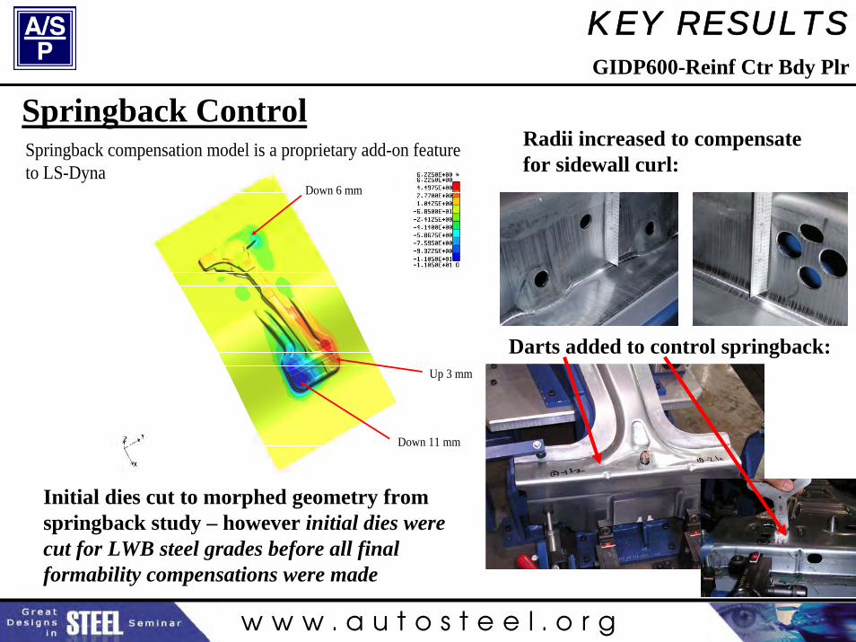
Springback ControlSpringback compensation model is a proprietary add-on feature to LS-Dyna
Down 6 mm
Down 11 mm
Up 3 mm
Radii increased to compensate for sidewall curl:
Darts added to control springback:
Initial dies cut to morphed geometry from springback study – however initial dies were cut for LWB steel grades before all final formability compensations were made
GIDP600-Reinf Ctr Bdy Plr

w w w . a u t o s t e e l . o r g
KEY RESULTS
Insights gained during production• Premature wear on the draw beads after a 1000 parts.
Substituted hard weld to correct the issue.• Binder is scored and has micro-fractures• Major Heat buildup in the draw die • Tool breakage issues due mainly to improper die construction• Ram tilt experienced during production
Draw die & line dies are all under one ram. The large amount of tonnage required in the draw die caused the ram tilt. Added nitrogen cylinders to the final operation to balance out the ram.
•Flexing flange die.Trim clearance was ok in static condition. Upper and lower trim steels strike when press is cycled. Picture shows 0.4 mm step worn into upper trim steel after 1500 hits. Caldie steelsinserted in place of existing trim steels.
GIDP600-Reinf Ctr Bdy Plr

w w w . a u t o s t e e l . o r g
KEY RESULTS
Major Lessons Learned• Springback compensation software is useful, but do not apply until
all formability problems are resolved.
• Keep B-pillar length-of-line constant, if possible, from rocker to roof to stiffen draw panel and minimize camber, twist.
• Restriking AHSS is acceptable to tighten radii or over bend to compensate springback, but not to move previously work hardened metal.
• Try to run draw stage in its own press to balance loads, avoid tilt.
• Sidewalls should be designed with open angles to facilitate overbending for springback compensation. Six degrees should be adequate for DP600.
GIDP600-Reinf Ctr Bdy Plr

w w w . a u t o s t e e l . o r g
KEY RESULTS
Major Lessons Learned• Higher DP600 strength required at least one tool material upgrade
for draw beads, trim steels.
• Higher DP600 strength requires overall upgrade in tool robustness.
• Both hard check fixture and white light scanning are recommended. The greater springback encountered in AHSS may be too large for the fixture to accurately measure, but hard check fixture still needed for instant feedback.
• Higher loads with DP600 caused die flexing during flanging. Consider upgrading flange die standards to higher stiffness to minimize flexing under larger flanging thrust loads.
GIDP600-Reinf Ctr Bdy Plr
w w w . a u t o s t e e l . o r g
KEY RESULTS
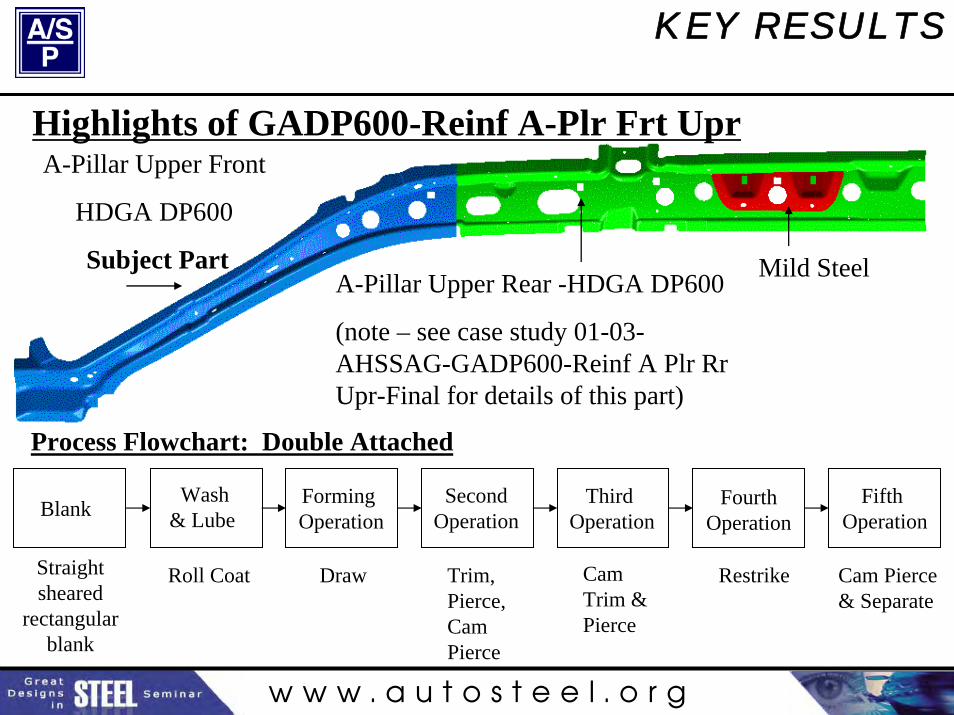
A-Pillar Upper Rear -HDGA DP600
(note – see case study 01-03-AHSSAG-GADP600-Reinf A Plr RrUpr-Final for details of this part)
A-Pillar Upper Front
HDGA DP600
Subject Part Mild Steel
Highlights of GADP600-Reinf A-Plr Frt Upr
Straight sheared
rectangular blank
Wash& Lube
FormingOperation
SecondOperation
Third Operation
Fourth Operation
Fifth OperationBlank
Roll Coat Draw Trim, Pierce, Cam Pierce
CamTrim &Pierce
Restrike Cam Pierce& Separate
Process Flowchart: Double Attached

w w w . a u t o s t e e l . o r g
KEY RESULTS
From this-----------------------------------------------to this
Geometry Concessions for Wrinkling
Autoform
GADP600-Reinf A-Plr Frt Upr

w w w . a u t o s t e e l . o r g
KEY RESULTS
Green 125N bead
Dark blue 25N bead
Blue 300N bead
Orange 50N bead
Red 250N bead
Purple 325N beadDraw Bead Layout
GADP600-Reinf A-Plr Frt Upr
w w w . a u t o s t e e l . o r g
KEY RESULTS
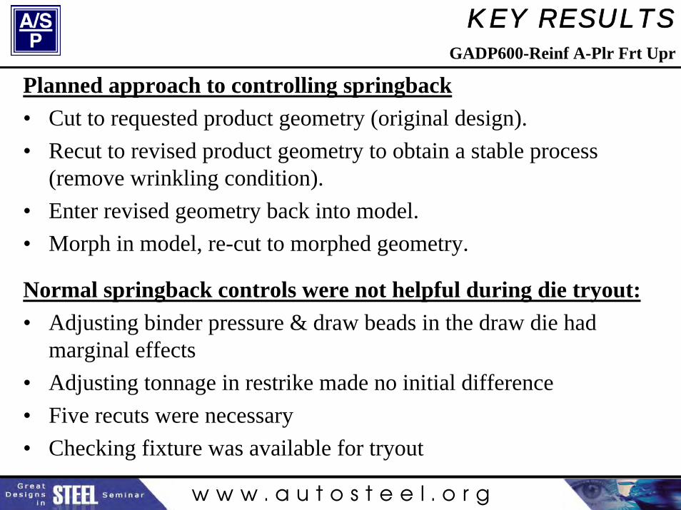
Planned approach to controlling springback• Cut to requested product geometry (original design).• Recut to revised product geometry to obtain a stable process
(remove wrinkling condition).• Enter revised geometry back into model.• Morph in model, re-cut to morphed geometry.
Normal springback controls were not helpful during die tryout:• Adjusting binder pressure & draw beads in the draw die had
marginal effects• Adjusting tonnage in restrike made no initial difference• Five recuts were necessary• Checking fixture was available for tryout
GADP600-Reinf A-Plr Frt Upr

w w w . a u t o s t e e l . o r g
KEY RESULTS
Unanticipated Formability Problems• Draw panel split, and restrike panel cracked, in
regions not predicted by FLD.
• Draw panel re-modeled with FLD adjusted to match actual failures, and process modified to eliminate splitting under new local failure criteria
Initial Autoform Result Autoform with Adjusted FLD
GADP600-Reinf A-Plr Frt Upr
w w w . a u t o s t e e l . o r g
KEY RESULTS
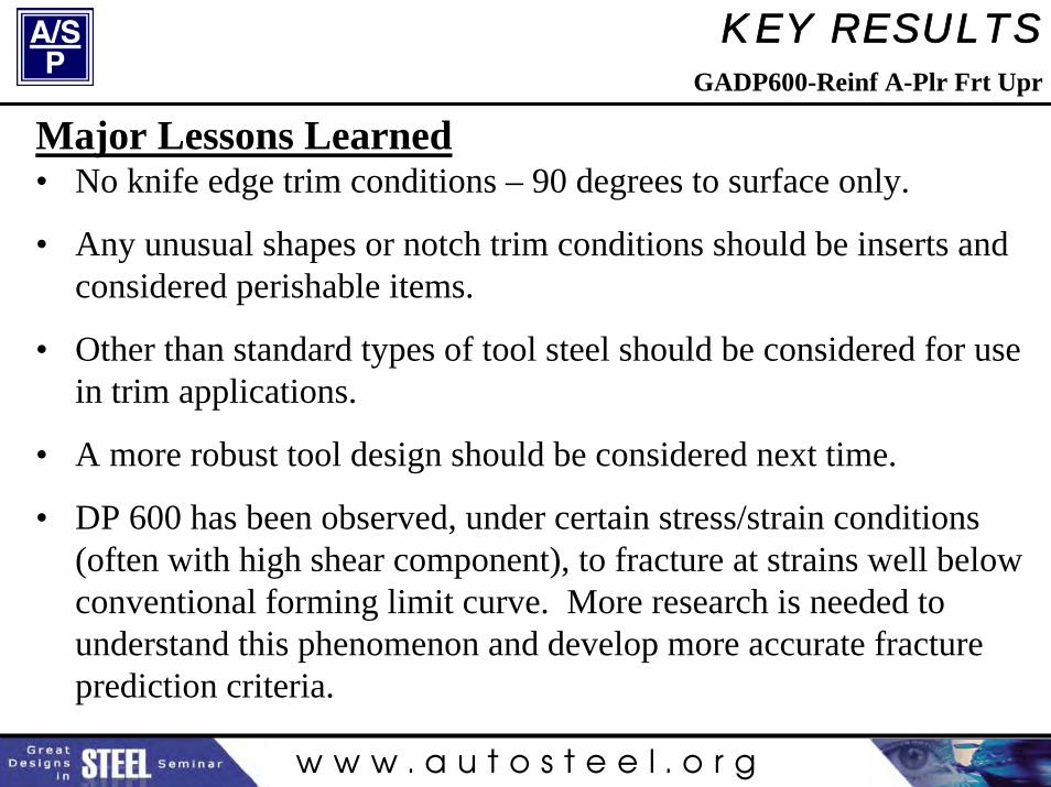
Major Lessons Learned• No knife edge trim conditions – 90 degrees to surface only.
• Any unusual shapes or notch trim conditions should be inserts and considered perishable items.
• Other than standard types of tool steel should be considered for use in trim applications.
• A more robust tool design should be considered next time.
• DP 600 has been observed, under certain stress/strain conditions(often with high shear component), to fracture at strains well below conventional forming limit curve. More research is needed to understand this phenomenon and develop more accurate fracture prediction criteria.
GADP600-Reinf A-Plr Frt Upr

w w w . a u t o s t e e l . o r g
FUTURE PLANS
Adding Additional Case Studies to Database• Compiling 3 to 6 additional case studies per quarter.
• Priority on most challenging components – rockers, pillars, rails.
• Gathering additional 780, 980 UTS cases.
• Expand to include multiple forming methods for an individual part.
• Continue until A/SP AHSS Formability project develops recommended practices for a full range of components
Additional participation from the local die development and tier 1 stamping community
would be warmly welcomed!

w w w . a u t o s t e e l . o r g
AHSS AG ON THE WEB
Current and future case studies can be downloaded from the A/SP public website at:
http://www.a-sp.org/publications.htm
Or for more information, please contact:
Blake Zuidema Mike BzdokArcelor Mittal A/SP(219) 399-2913 (248) [email protected] [email protected]