advanced flow engineering - catalograck
TRANSCRIPT

advanced FLOW engineeringInstruction Manual P/N: 42-24021 DFS780 PRO
Make: GM Model: 2500/3500 Year: 2017-2019 Engine: V8-6.6L (td) Duramax

Label Qty. Description Part Number
A 1 Fuel Manifold Assembly 05-60584
B 1 Filter, Fuel 44-FF019
C 1 Bracket, Frame; Carbon Steel 05-60795
D 4 Washer, M6 (Fiber) 03-50457
E 4 Washer, M6 03-50444
F 4 Locknut, Flanged: M6 03-50445
G 4 Bolt: M6 x 1.0 x 50mm 03-50443
H 3 Rivet, Nuts 03-50569
I 1 Screw, Hex Hd Cap: 3/8"-16 Flange 03-50046
J 3 Nut: 3/8"-16 Flange 05-40103
K 3 Washer, Flat: 3/8" AN 03-50230
L 12 Ties, Nylon Cable, 12" 05-60167
M 1 Connector, Add a harness & Fuse (Micro 2) 05-60691
N 3 Bolt: 3/8"-16 x 1" 03-50124
O 1 Fitting, 1/2" Push-On to -8 AN (Straight) 03-50549B
P 1 Clamp, Spring; 7/16" 05-60578
Q 1 Fitting, 1/2" Push-On to -8 AN (90°) 05-60683B
R 1 Harness, Power 05-60632
S 1 Harness, Relay 05-60551
T 1 Hose, Fuel Inlet/Outlet 05-60861
U 1 Hose, Fuel Return 05-60860
V 1 Nut, 3/8"-16 05-50568
W 1 Washer, Flat: 3/8" ID, 1.25 OD. 03-50488
X 2 Fitting: 3/8" NPT to -8 AN (Straight) 05-60685
• Please read the entire instruction manual before proceeding.• Ensure all components listed are present.• If you are missing any of the components, call customer support at 951-493-7100.• Ensure you have all necessary tools before proceeding.• Do not attempt to work on your vehicle when the engine is hot.• Disconnect the negative battery terminal before proceeding.• Retain factory parts for future use.
Page 2Warranty Information available at: https://afepower.com/contact#warranty

aFepower.comPage 3
T
Q
R
P
S
X
L
U
DE
F G I H
VWN
C
JK
B
A
M
O

Step 1: Mount the supplied fuel manifold assembly to the supplied carbon steel frame bracket using the supplied hardware and tighten:
•(4) M6 x1.0 x 50mm bolts •(4) M6 washers •(4) M6 fiber washers •(4) M6 flanged locknuts Note: The fiber washers go between the fuel manifold assembly and the carbon steel bracket.
Step 2: Install the two (2) supplied 3/8" NPT to -8 AN fittings to the fuel manifold using thread sealant. Note: Installing the fuel filter loosely will give you an idea of the overall assembly size when looking for a mounting location.
Step 3: Mount the fuel manifold assembly to the truck. When looking for a location to mount the assembly, please make sure you take into account the length of hose that was supplied as well as the orientation of the inlet and outlet ports.
Page 4
OUTLET INLET

Note: Be careful when drilling. Check behind where you are drilling for anything that might get damaged and move it before drilling.
Step 4: If you are using the supplied rivet nuts, you will need to drill three (3) 17/32" holes into sheet metal with a minimum thickness of 5/32" (0.156”). Otherwise, you will need to drill three (3) 3/8” holes into sheet metal with a minimum thickness of 3/16” (0.188”). Step 5: If installing the rivet nuts, use the supplied 3/8"-16 x 1-½" bolt, 3/8"-16 nut and 3/8" flat washer to make the installation tool (as shown below).
aFepower.comPage 5

Page 6
Step 6: Using the tool assembled in Step 5, attach the rivet nut to the drilled material by holding the bolt steady and turning the nut clockwise. This will force the rivet nut to collapse and tighten onto the drilled material.Step 7: Install the fuel manifold assembly and the carbon steel frame bracket to the frame using the supplied harware and tighten:
•(3) 3/8" - 16 x 1" bolts •(3) 3/8" AN washers •(3) 3/8"- 16 flanged nuts (if not using the rivet nuts)
Step 8: Install the supplied fuel filter and tighten.Step 9: Find the factory fuel supply lines. They are located on top of the factory fuel tank.
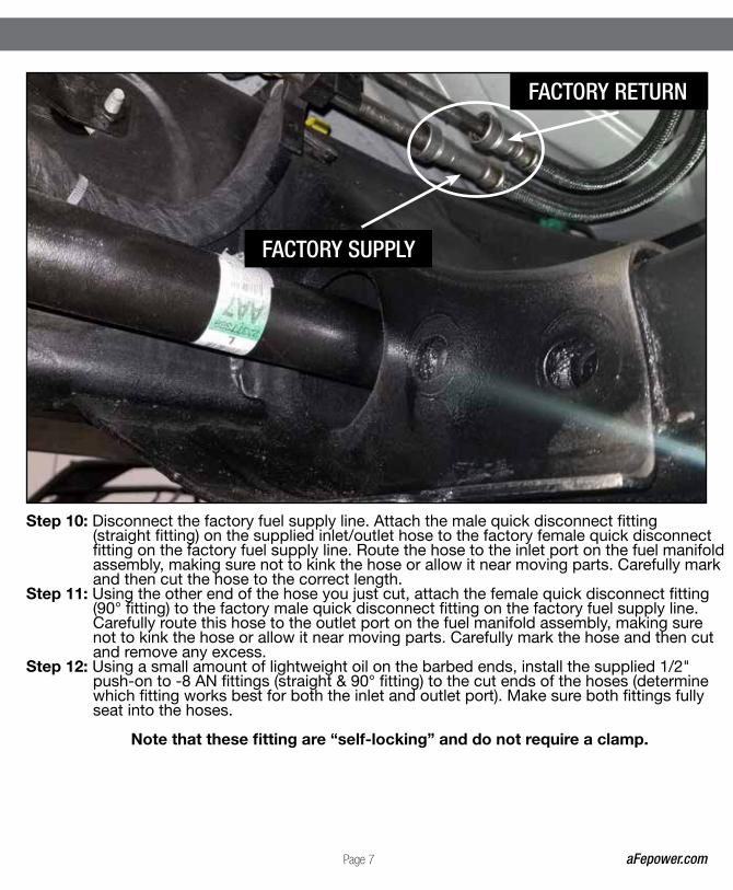
Step 10: Disconnect the factory fuel supply line. Attach the male quick disconnect fitting (straight fitting) on the supplied inlet/outlet hose to the factory female quick disconnect fitting on the factory fuel supply line. Route the hose to the inlet port on the fuel manifold assembly, making sure not to kink the hose or allow it near moving parts. Carefully mark and then cut the hose to the correct length.Step 11: Using the other end of the hose you just cut, attach the female quick disconnect fitting (90° fitting) to the factory male quick disconnect fitting on the factory fuel supply line. Carefully route this hose to the outlet port on the fuel manifold assembly, making sure not to kink the hose or allow it near moving parts. Carefully mark the hose and then cut and remove any excess.Step 12: Using a small amount of lightweight oil on the barbed ends, install the supplied 1/2" push-on to -8 AN fittings (straight & 90° fitting) to the cut ends of the hoses (determine which fitting works best for both the inlet and outlet port). Make sure both fittings fully seat into the hoses.
Note that these fitting are “self-locking” and do not require a clamp.
aFepower.comPage 7
FACTORY SUPPLY
FACTORY RETURN

Page 8
Step 13: Attach the fittings to the inlet & outlet ports of the fuel manifold assembly. Make sure all connections are tight.
OUTLET
INLET

aFepower.comPage 9
Step 14: Disconnect the factory fuel return line. Attach the supplied fuel return hose between the male and female factory fuel fittings. Push all connections together.
RETURN LINE

Step 15: Carefully route the ¼" hose to the fitting on the top of the fuel manifold assembly, making sure not to kink the hose or allow it near moving parts. Carefully mark and then cut the hose to the correct length. Using the supplied spring clamp, attach the hose to the nipple on the top of the air chamber on the fuel manifold assembly.
Page 10

aFepower.comPage 11
Step 16: Plug the Deutsch connector on the end of the supplied power harness into the mating connector on the fuel manifold assembly motor.Step 17: Route the power harness along the inside of the frame and into the engine compartment.Step 18: Organize the power harness and secure with the supplied nylon cable ties.Step 19: Connect the red wire ring terminal on the power harness to the positive side of the battery. Note: Check the fuse to make sure it is already installed in the connector.
Step 20: Connect the black wire ring terminal on the power harness to the negative side of the battery.Step 21: Plug the supplied relay harness into the Deutsch connector on the power harness.Step 22: Secure the relay harness using a supplied cable tie.Step 23: Remove the fuse box cover. Locate a 12-volt source inside the fuse box that only comes on with the key in the “run” position. Once a 12-volt source is located, remove the fuse from the fuse box. Locations for 12 volt fuse (under the dash fuse block): 2017: Location: #41

Page 12
Step 24: Attach the power wire from the relay harness to the add-a-harness fuse connector.Step 25: Insert the fuse removed in Step 23 into the open location on the add a harness fuse connector (not in line with the wire).Step 26: Insert the add a harness fuse connector (with installed fuses) into the 12-volt source location from Step 23.Step 27: Carefully route the power wire outside the fuse box and reinstall the cover (making sure, not to pinch the wire).Step 28: Organize the wire harnesses and secure with the remaining nylon cable ties.Step 30: Turn the key to the “Run” position and wait for 30 seconds. Start the engine.Step 31: Installation is now complete. Make sure that all fittings are tight and that fuel is not leaking from any of the connections made during installation.
NOTE: Place enclosed CARB EO sticker on or near the device on a smooth, clean surface. EO identification label is required to pass the smog test inspection.

Page 13
Page left blank intentionally

Page 14
Page left blank intentionally

aFepower.comPage 15
Page left blank intentionally

7
advanced FLOW engineering, inc.252 Granite Street Corona, CA 92879
TEL: 951.493.7100 • TECH: 951.493.7100 x23E-Mail:[email protected]
P/N: 06-81019