advanced energy systems: overview & electron … energy systems inc. 27 industrial blvd unit e....
TRANSCRIPT
Putting Accelerator Technology to WorkTJS – MEIC 3-15 - 1
Advanced Energy Systems Inc.27 Industrial Blvd Unit EMedford, NY 11763Phone: (631) 345-6264 x 112Fax: (631-345-0459E-mail: [email protected] SchultheissTom Schultheiss
Advanced Energy Systems:Overview & Electron Sources
JLAB – March 2015
Putting Accelerator Technology to WorkTJS – MEIC 3-15 - 2
Outline•
AES Overview
•
Integrated Engineering and Physics Services
•
Advanced Radiation Sources−
High-Current Electron Injectors−
Photocathode−
Thermionic−
High-Current Cryomodules−
High-Power RF Couplers and Windows
•
Turnkey Accelerators and Components–
SRF Cavity Projects–
Turnkey Beamlines
•
Contacts

Putting Accelerator Technology to WorkTJS – MEIC 3-15 - 3
Advanced Energy Systems (AES)
Mission StatementAES seeks to be the supplier of choice for advanced radiation sources based on high-brightness electron accelerator technology. AES teams with market leaders in the medical imaging, homeland security,
defense and other industries to provide systems for cancer and drug discovery, non-destructive evaluation and force protection. AES is committed to providing best value and AES reliability with unsurpassed after sale support.
Corporate Profile•
Privately held company incorporated in New York in September 1998 (formerly an operating group of Northrop Grumman)
•
Headquartered in Medford, NY with offices in Princeton, NJ and Newport News, VA
•
24 employees•
Annual sales of ~ $6M•
NC prototype machine shop including buffered chemical polishing (BCP) lab and e-beam welding capability
•
State-of-the-art engineering and physics design and analysis capability
•
ISO 9001-2008 with Design re-certified in July 2012
Laser ElectronAccelerator Facility
(BNL)
Princeton, NJ
MedfordNY

Putting Accelerator Technology to WorkTJS – MEIC 3-15 - 4
AES Evolution•
Formed within Grumman in 1975 to support the Tokamak Fusion Test Reactor (TFTR) project at the Princeton Plasma Physics Laboratory (PPPL)
•
Strategic Defense Initiative (SDI) involvement in Accelerator Technology began in 1984 with the Beam Experiments Aboard Rockets (BEAR) project
•
Relativistic Heavy Ion Collider (RHIC) superconducting magnet fabrication from 1992 to 1994
•
Monochromatic X-Ray Imaging System (MXIS) & Laser Electron Accelerator Facility (LEAF) are examples of AES transition to accelerator applications
•
Spun off by Northrop Grumman in September 1998
•
Over $400M in Sales between from 1975 to 1998FUSION
SDI
ACCELERATORTECHNOLOGY
CWDD1990
LEAF
1998
TFTR
1980
RHIC
1994
MAGNETS

Putting Accelerator Technology to WorkTJS – MEIC 3-15 - 5
Advanced Energy SystemsMission StatementMission StatementAES seeks to be the supplier of choice for advanced radiation sources based on high-brightness electron accelerator technology.
Product AreasProduct Areas•
Advanced Radiation Sources•
Free Electron Lasers (FEL)•
High-Power Microwaves (HPM)•
High-Power TeraHertz (THz) Sources•
Tunable, Monochromatic X-Ray Sources
•
Turnkey Accelerator Systems & Components•
Photocathode Injectors•
Superconducting RF (SRF) Accelerators•
Normal-Conducting Accelerators•
Beam & Optical Transport Systems•
Turnkey Beamlines
•
Integrated Engineering & Physics Services
MXISystems
MedfordMachine
ShopChemistry
Facility
JLABFELTHz
BeamlineSingle-Cell
SRF Cavities
Putting Accelerator Technology to WorkTJS – MEIC 3-15 - 6
AES Medford Machining and SRF Facilities
Putting Accelerator Technology to WorkTJS – MEIC 3-15 - 7
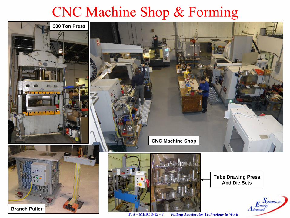
CNC Machine Shop & Forming
CNC Machine Shop
300 Ton Press
Branch Puller
Tube Drawing PressAnd Die Sets
Putting Accelerator Technology to WorkTJS – MEIC 3-15 - 8
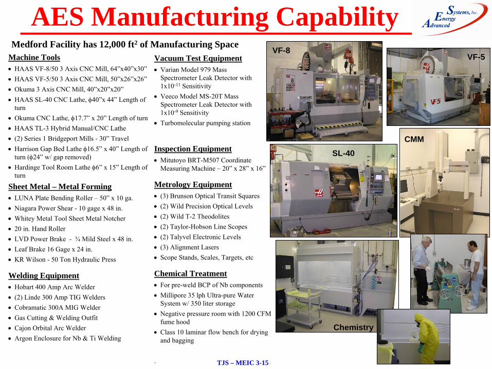
Machine Tools
HAAS VF-8/50 3 Axis CNC Mill, 64”x40”x30”
HAAS VF-5/50 3 Axis CNC Mill, 50”x26”x26”
Okuma 3 Axis CNC Mill, 40”x20”x20”
HAAS SL-40 CNC Lathe, 40”x 44”
Length of turn
Okuma CNC Lathe, 17.7”
x 20”
Length of turn
HAAS TL-3 Hybrid Manual/CNC Lathe
(2) Series 1 Bridgeport Mills -
30”
Travel
Harrison Gap Bed Lathe 16.5”
x 40”
Length of turn (24”
w/ gap removed)
Hardinge Tool Room Lathe 6”
x 15”
Length of turn
Sheet Metal – Metal Forming
LUNA Plate Bending Roller –
50”
x 10 ga.
Niagara Power Shear -
10 gage x 48 in.
Whitey Metal Tool Sheet Metal Notcher
20 in. Hand Roller
LVD Power Brake -
¾
Mild Steel x 48 in.
Leaf Brake 16 Gage x 24 in.
KR Wilson -
50 Ton Hydraulic Press
Welding Equipment
Hobart 400 Amp Arc Welder
(2) Linde 300 Amp TIG Welders
Cobramatic 300A MIG Welder
Gas Cutting & Welding Outfit
Cajon Orbital Arc Welder
Argon Enclosure for Nb & Ti Welding
Inspection Equipment
Mitutoyo BRT-M507 Coordinate Measuring Machine –
20”
x 28”
x 16”
Metrology Equipment
(3) Brunson Optical Transit Squares
(2) Wild Precision Optical Levels
(2) Wild T-2 Theodolites
(2) Taylor-Hobson Line Scopes
(2) Talyvel Electronic Levels
(3) Alignment Lasers
Scope Stands, Scales, Targets, etc
Chemical Treatment
For pre-weld BCP of Nb components
Millipore 35 lph Ultra-pure Water System w/ 350 liter storage
Negative pressure room with 1200 CFM fume hood
Class 10 laminar flow bench for drying and bagging
.
VF-8VF-5
SL-40CMM
Medford Facility has 12,000 ft2 of Manufacturing SpaceVacuum Test Equipment
Varian Model 979 Mass Spectrometer Leak Detector with 1x10-11
Sensitivity
Veeco Model MS-20T Mass Spectrometer Leak Detector with 1x10⁻⁹
Sensitivity
Turbomolecular pumping station
Chemistry
AES Manufacturing Capability
Putting Accelerator Technology to WorkTJS – MEIC 3-15 - 9
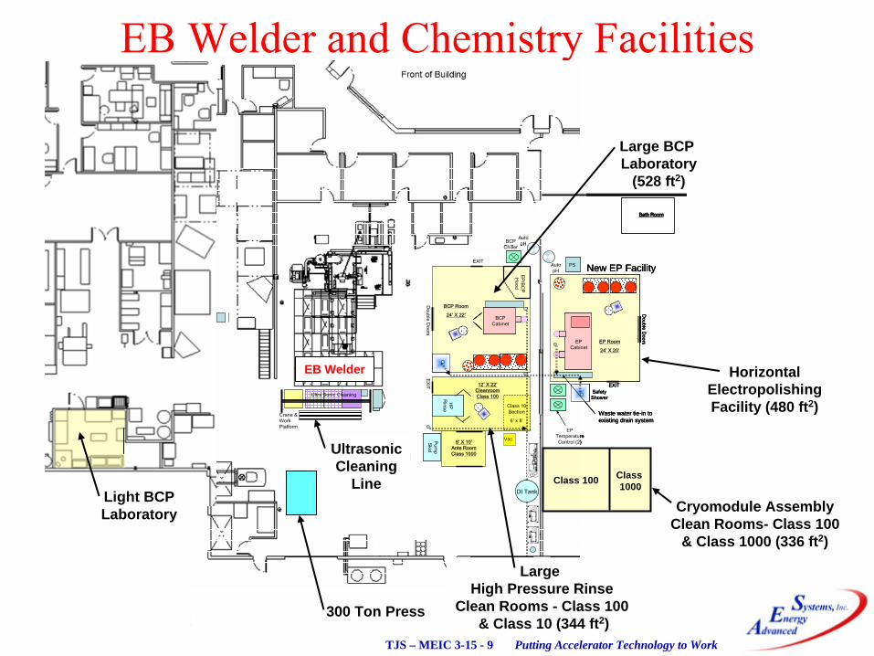
EB Welder and Chemistry Facilities
12’ X 22’Cleanroom Class 100
HP
Rinse
Auto pH
Vac.
Class 10 Section
6’ x 8’
BCP Room
24’ X 22’
Double D
oorsPum
p Skid
DI Tank
10,000 gal
Drywell
Crane & Work Platform
8’ X 10’Ante Room Class 1000
EXIT
EXIT
BCP Chiller
BCP Cabinet
EP/BCP
Hood
Ultra Sonic Cleaning
New EP Facility
Existing Processing
Area
EXIT
Double D
oors
Waste water tie-in to existing drain system
Auto pH
EP Temperature Control (2)
EP Cabinet
PS
Bath Room
EP Room
24’ X 20’
Safety Shower
12’ X 22’Cleanroom Class 100
HP
RinseH
P R
inse
Auto pH
Vac.Vac.
Class 10 Section
6’ x 8’
Class 10 Section
6’ x 8’
BCP Room
24’ X 22’
Double D
oorsPum
p Skid
Pump
Skid
DI TankDI Tank
10,000 gal
Drywell
10,000 gal
Drywell
Crane & Work Platform
8’ X 10’Ante Room Class 1000
EXIT
EXIT
BCP Chiller
BCP Cabinet
BCP Cabinet
BCP Cabinet
BCP Cabinet
EP/BCP
Hood
Ultra Sonic Cleaning
New EP Facility
Existing Processing
Area
EXIT
Double D
oors
Waste water tie-in to existing drain system
Auto pH
EP Temperature Control (2)
EP Cabinet
EP Cabinet
PSPS
Bath Room
EP Room
24’ X 20’
Safety Shower
Large BCP Laboratory
(528 ft2)
Large High Pressure Rinse
Clean Rooms - Class 100& Class 10 (344 ft2)
HorizontalElectropolishingFacility (480 ft2)
EB Welder
UltrasonicCleaning
Line
300 Ton Press
Light BCPLaboratory Cryomodule Assembly
Clean Rooms- Class 100& Class 1000 (336 ft2)
Class 100 Class 1000
Putting Accelerator Technology to WorkTJS – MEIC 3-15 - 10
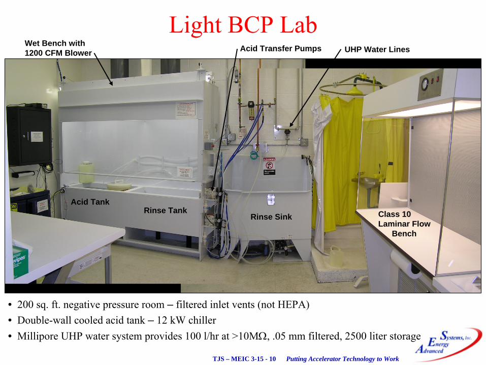
Light BCP Lab
• 200 sq. ft. negative pressure room – filtered inlet vents (not HEPA)• Double-wall cooled acid tank – 12 kW chiller• Millipore UHP water system provides 100 l/hr at >10M, .05
mm filtered, 2500 liter storage
Wet Bench with1200 CFM Blower
Acid TankRinse Tank
Rinse Sink Class 10Laminar Flow
Bench
UHP Water LinesAcid Transfer Pumps

Putting Accelerator Technology to WorkTJS – MEIC 3-15 - 11
EB Welder at AES (Shown Prior to Clean Room Instl)
PTR 150 kV, 100 mA5’ x 7’ x 10’ Chamber5-axis CNC control
Diffusion pump w/ cooled baffle using DC-705 oilCryo Meissner Coil – 200,000 l/s for water vapor
Putting Accelerator Technology to WorkTJS – MEIC 3-15 - 12
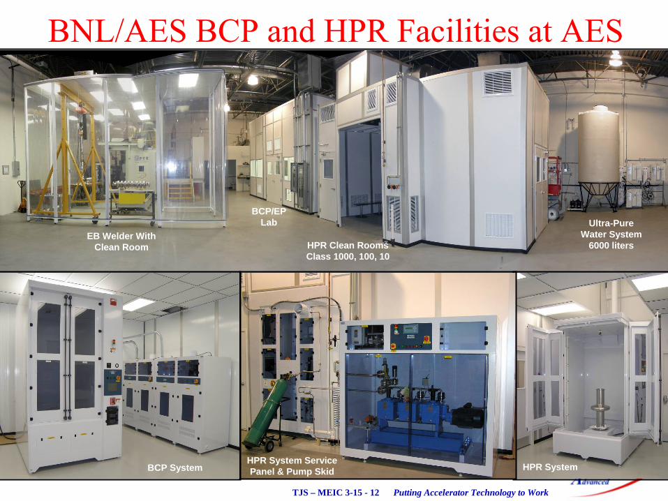
Installation of BCP and HPR Facilities at AES
EB Welder WithClean Room
BCP/EP Lab
HPR Clean RoomsClass 1000, 100, 10
Ultra-PureWater System
6000 liters
HPR SystemHPR System ServicePanel & Pump SkidBCP System
BNL/AES BCP and HPR Facilities at AES

Putting Accelerator Technology to WorkTJS – MEIC 3-15 - 13
Electropolishing Facility
•
Designed and Built under contract to Fermlab

Putting Accelerator Technology to WorkTJS – MEIC 3-15 - 14
AES Princeton RF & THz Test Facility
AES Princeton Office100 Forrestal RoadSuite EPrinceton, NJ 08540Princeton University Forrestal Campus
Putting Accelerator Technology to WorkTJS – MEIC 3-15 - 15
Outline•
AES Overview
•
Integrated Engineering and Physics Services
•
Advanced Radiation Sources−
High-Current Electron Injectors−
Photocathode−
Thermionic−
High-Current Cryomodules−
High-Power RF Couplers and Windows
•
Turnkey Accelerators and Components–
SRF Cavity Projects–
Turnkey Beamlines
•
Contacts
Putting Accelerator Technology to WorkTJS – MEIC 3-15 - 16
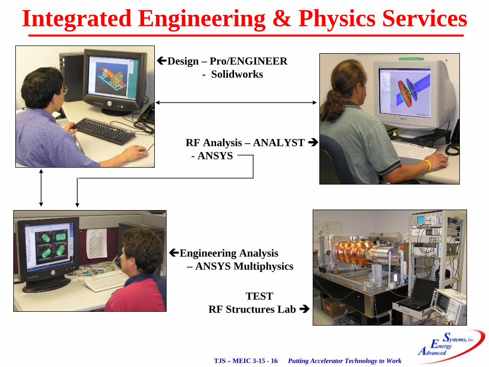
Design – Pro/ENGINEER- Solidworks
RF Analysis – ANALYST - ANSYS
Engineering Analysis – ANSYS Multiphysics
TESTRF Structures Lab
Integrated Engineering & Physics Services
Putting Accelerator Technology to WorkTJS – MEIC 3-15 - 17
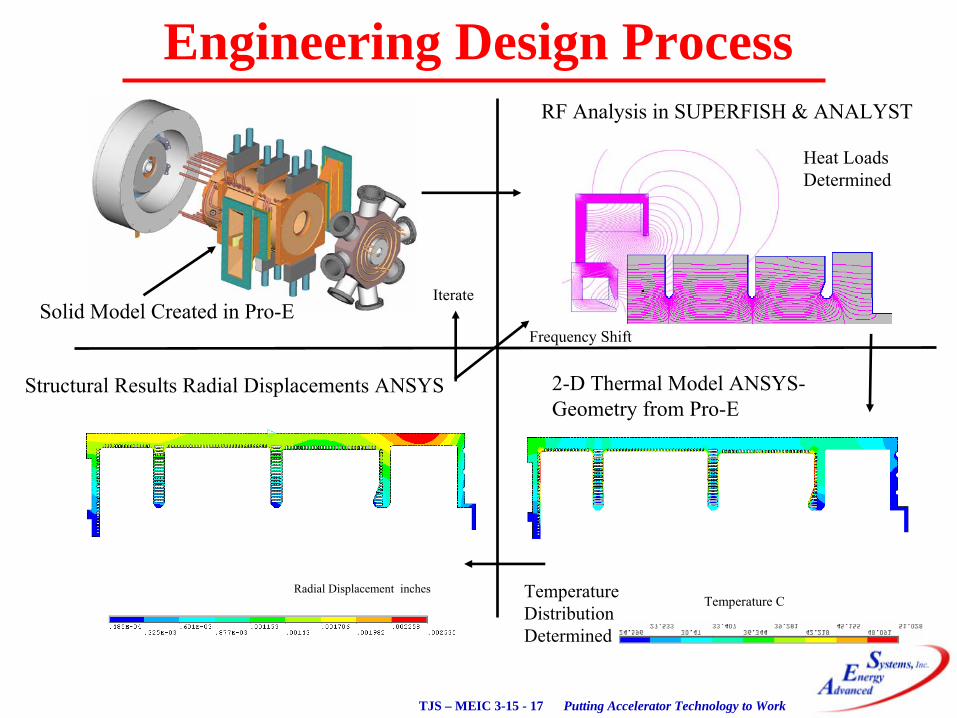
Engineering Design Process
Solid Model Created in Pro-E
Temperature CRadial Displacement inches
RF Analysis in SUPERFISH & ANALYST
2-D Thermal Model ANSYS-
Geometry from Pro-E
Structural Results Radial Displacements ANSYS
Heat Loads Determined
Temperature Distribution Determined
Frequency Shift
Iterate
Putting Accelerator Technology to WorkTJS – MEIC 3-15 - 18
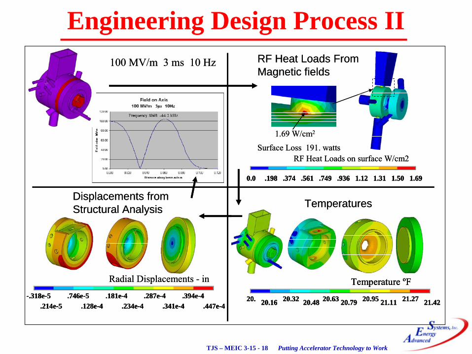
Engineering Design Process II 100 MV/m 3 ms 10 Hz
Surface Loss 191. watts
0.0 .198 .374 .561 .749 .936 1.12 1.31 1.50 1.69
RF Heat Loads on surface W/cm2
1.69 W/cm2
RF Heat Loads From Magnetic fields
20. 20.16 20.32 20.48 20.63 20.79 20.95 21.11 21.27 21.42
Temperature ºF
Temperatures
-.318e-5.214e-5
.746e-5.128e-4
.181e-4.234e-4
.287e-4.341e-4
.394e-4.447e-4
Radial Displacements - in
Displacements from Structural Analysis
100 MV/m 3 ms 10 Hz
Surface Loss 191. watts
0.0 .198 .374 .561 .749 .936 1.12 1.31 1.50 1.690.0 .198 .374 .561 .749 .936 1.12 1.31 1.50 1.69
RF Heat Loads on surface W/cm2
1.69 W/cm2
RF Heat Loads From Magnetic fields
20. 20.16 20.32 20.48 20.63 20.79 20.95 21.11 21.27 21.42
Temperature ºF
20. 20.16 20.32 20.48 20.63 20.79 20.95 21.11 21.27 21.42
Temperature ºF
Temperatures
-.318e-5.214e-5
.746e-5.128e-4
.181e-4.234e-4
.287e-4.341e-4
.394e-4.447e-4
-.318e-5.214e-5
.746e-5.128e-4
.181e-4.234e-4
.287e-4.341e-4
.394e-4.447e-4
Radial Displacements - in
Displacements from Structural Analysis

Putting Accelerator Technology to WorkTJS – MEIC 3-15 - 19
Shipboard Integration
FEL
10-4
10-3
10-2
10-1
100
101
102
1 1.5 2 2.5 3 3.5 4
Maritime AtmosphereMarine Aerosol, Horizontal Path
Wavelength (m)
Extinction
AbsorptionScattering
10-4
10-3
10-2
10-1
100
101
102
1 1.5 2 2.5 3 3.5 4
Maritime AtmosphereMarine Aerosol, Horizontal Path
Wavelength (m)
Extinction
AbsorptionScattering
Propagation
Accelerator
FELSIMMediator
Mission
IR Optics& BCS
Systems Engineering Analysis & Modeling

Putting Accelerator Technology to WorkTJS – MEIC 3-15 - 20
Outline•
AES Overview
•
Integrated Engineering and Physics Services
•
Advanced Radiation Sources−
High-Current Electron Injectors−
Photocathode−
Thermionic−
High-Current Cryomodules−
High-Power RF Couplers and Windows
•
Turnkey Accelerators and Components–
SRF Cavity Projects–
Turnkey Beamlines
•
Contacts
Putting Accelerator Technology to WorkTJS – MEIC 3-15 - 21
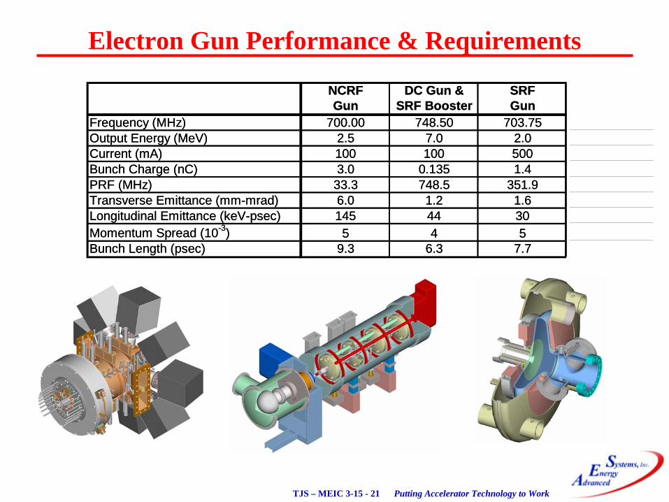
Electron Gun Performance & Requirements
NCRF DC Gun & SRFGun SRF Booster Gun
Frequency (MHz) 700.00 748.50 703.75Output Energy (MeV) 2.5 7.0 2.0Current (mA) 100 100 500Bunch Charge (nC) 3.0 0.135 1.4PRF (MHz) 33.3 748.5 351.9Transverse Emittance (mm-mrad) 6.0 1.2 1.6Longitudinal Emittance (keV-psec) 145 44 30Momentum Spread (10-3) 5 4 5Bunch Length (psec) 9.3 6.3 7.7

Putting Accelerator Technology to WorkTJS – MEIC 3-15 - 22
High-Current Electron Injector Options
DCGun
Spaceframe
HeliumVessel
ColdBox Cold
Box
Emittance Compensation
Solenoid
RF Feed
Cathode Backplate Cooling
750 MHzFundamental
SRF Cells
DC Gun & SRF Booster
Normal Conducting Gun
FocusingSolenoidMagnet
VacuumChamber
with Pumps
RidgeLoaded
Waveguide
Vacuum Pumps
BuckingSolenoidMagnet
Power CouplerPort
Helium Vessel
Quarter Wave Choke
Cathode Assembly
NiobiumCavityAssembly
SRF Gun
2245.5 MHz3rd
Harmonic SRF CellWith RF W/G Feed
(not shown)
Putting Accelerator Technology to WorkTJS – MEIC 3-15 - 23
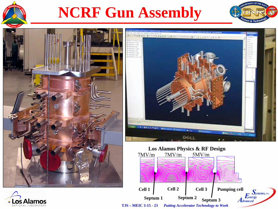
NCRF Gun Assembly
Septum 1 Septum 2
Cell 1 Cell 2 Cell 3 Pumping cell
Septum 3
7MV/m 7MV/m 5MV/mLos Alamos Physics & RF Design
Putting Accelerator Technology to WorkTJS – MEIC 3-15 - 24
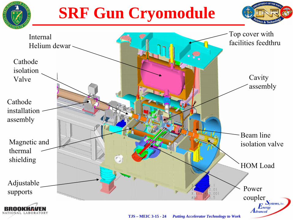
Cathode isolationValve
Cathode installationassembly
Beam lineisolation valve
Top cover withfacilities feedthru
Cavityassembly
InternalHelium dewar
Adjustable supports
Magnetic and thermalshielding
HOM Load
Powercoupler
SRF Gun Cryomodule
Putting Accelerator Technology to WorkTJS – MEIC 3-15 - 25
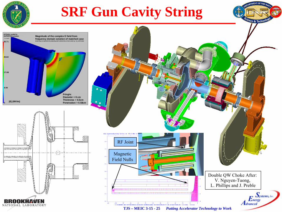
SRF Gun Cavity StringMagnitude of the complex E field fromfrequency domain solution of matched case(matching accomplished by adjusting wall conductivity so that cavity Q0 = QL with beam)
Pringle:Diameter = 6 cmThickness = 0.5cmPenetration = 0.58cm|E| (MV/m)
35.71
26.82
17.88
8.94
0
All fields scaled toSUPERFISH solution
RF Joint
MagneticField Nulls
Double QW Choke After: V. Nguyen-Tuong,
L. Phillips and J. Preble

Putting Accelerator Technology to WorkTJS – MEIC 3-15 - 26
Motivation for Gridded Thermionic Gun
•
Would like a thermionic electron gun for either high-performance or high-power applications where robustness, economics or footprint preclude a photocathode system.
•
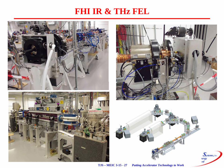
AES developed a CPI gridded thermionic electron gun integrated into a RF cavity for the Fritz Haber Institute as part of an IR and THz FEL–
H. P. Bluem, D. Dowell, A. M .M. Todd, L. M. Young, “High Brightness Thermionic Electron Gun Performance,”
WG1010, Proceedings of ERL2011, Tsukuba, Japan.
•
Budker
Institute of Nuclear Physics (BINP) developed a normal conducting thermionic-cathode injector–
“First test Results of RF Gun for the RacepTrack
Microtron
Recuperator of BINP SB RAS,”
Proc of RUPAC2012, tuppb049, St. Petersburg, Russia.
•
NRL proposed a gridded thermionic electron gun for high power FELs–
Physical Review Special Topics Accelerators and Beams 14, 020702 (2011)
•
“High Average Current Electron Gun for High Power Free Electron Lasers”
Spangle, et.al.
Putting Accelerator Technology to WorkTJS – MEIC 3-15 - 27
FHI IR & THz FEL
Putting Accelerator Technology to WorkTJS – MEIC 3-15 - 28
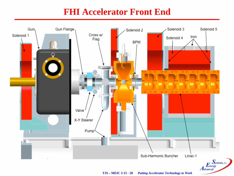
FHI Accelerator Front End
Putting Accelerator Technology to WorkTJS – MEIC 3-15 - 29
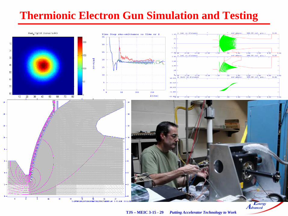
Thermionic Electron Gun Simulation and Testing
Putting Accelerator Technology to WorkTJS – MEIC 3-15 - 30
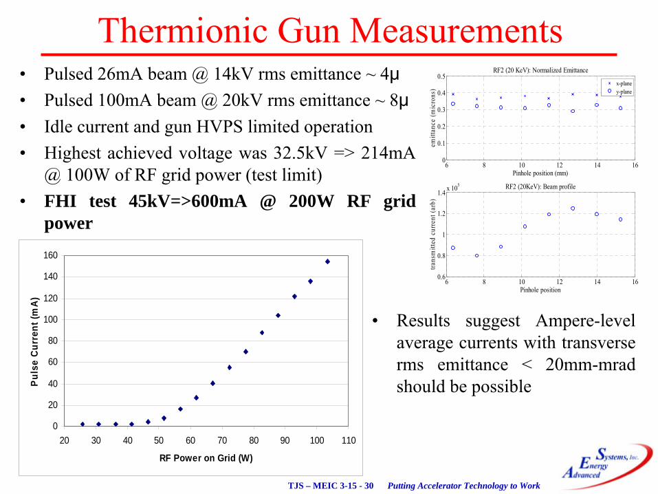
Thermionic Gun Measurements
6 8 10 12 14 160
0.1
0.2
0.3
0.4
0.5RF2 (20 KeV): Normalized Emittance
Pinhole position (mm)
emitt
ance
(mic
rons
)
x-planey-plane
6 8 10 12 14 160.6
0.8
1
1.2
1.4 x 10⁵ RF2 (20KeV): Beam profile
Pinhole position
trans
mitt
ed c
urre
nt (a
rb)
•
Pulsed 26mA beam @ 14kV rms
emittance ~ 4μ•
Pulsed 100mA beam @ 20kV rms
emittance ~ 8μ•
Idle current and gun HVPS limited operation•
Highest achieved voltage was 32.5kV => 214mA @ 100W of RF grid power (test limit)
•
FHI test 45kV=>600mA @ 200W RF grid power
•
Results suggest Ampere-level average currents with transverse rms
emittance < 20mm-mrad should be possible
0
20
40
60
80
100
120
140
160
20 30 40 50 60 70 80 90 100 110
RF Power on Grid (W)
Puls
e Cu
rren
t (m
A)

Putting Accelerator Technology to WorkTJS – MEIC 3-15 - 31
Normal Conducting Electron Guns
X-Band RF GunS-BandRF Gun
LEAF RF Gun
MXISystems RF Gun
Putting Accelerator Technology to WorkTJS – MEIC 3-15 - 32
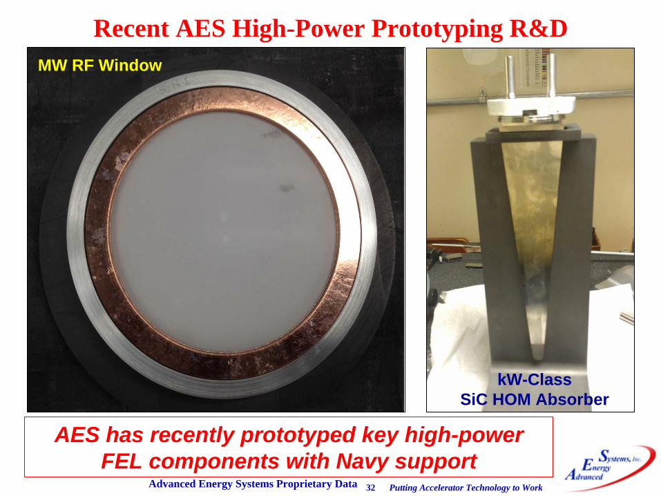
Recent AES High-Power Prototyping R&D
Advanced Energy Systems Proprietary Data
AES has recently prototyped key high-power FEL components with Navy support
MW RF Window
kW-Class SiC HOM Absorber

Putting Accelerator Technology to WorkTJS – MEIC 3-15 - 33
350 kW Power Coupler
Putting Accelerator Technology to WorkTJS – MEIC 3-15 - 34
Outline•
AES Overview
•
Integrated Engineering and Physics Services
•
Advanced Radiation Sources−
High-Current Electron Injectors−
Photocathode−
Thermionic−
High-Current Cryomodules−
High-Power RF Couplers and Windows
•
Turnkey Accelerators and Components–
SRF Cavity Projects–
Turnkey Beamlines
•
Contacts
Putting Accelerator Technology to WorkTJS – MEIC 3-15 - 35
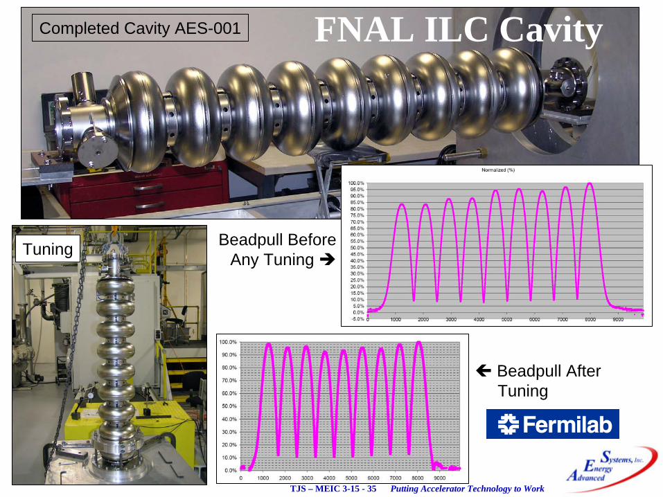
Completed Cavity AES-001
Tuning Beadpull BeforeAny Tuning
Beadpull AfterTuning
FNAL ILC Cavity
Putting Accelerator Technology to WorkTJS – MEIC 3-15 - 36
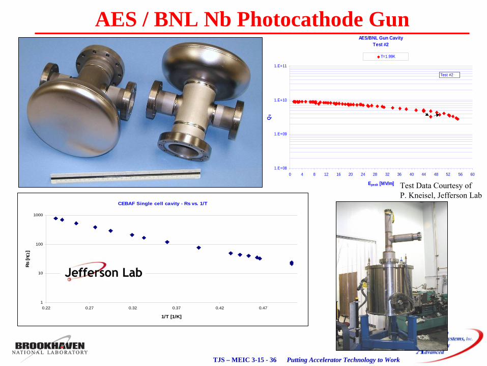
AES/BNL Gun CavityTest #2
1.E+08
1.E+09
1.E+10
1.E+11
0 4 8 12 16 20 24 28 32 36 40 44 48 52 56 60
Epeak [MV/m]
Q0
T=1.99K
Test #2
CEBAF Single cell cavity - Rs vs. 1/T
1
10
100
1000
0.22 0.27 0.32 0.37 0.42 0.47
1/T [1/K]
Rs [n
]
Test Data Courtesy of P. Kneisel, Jefferson Lab
AES / BNL Nb Photocathode Gun
Putting Accelerator Technology to WorkTJS – MEIC 3-15 - 37
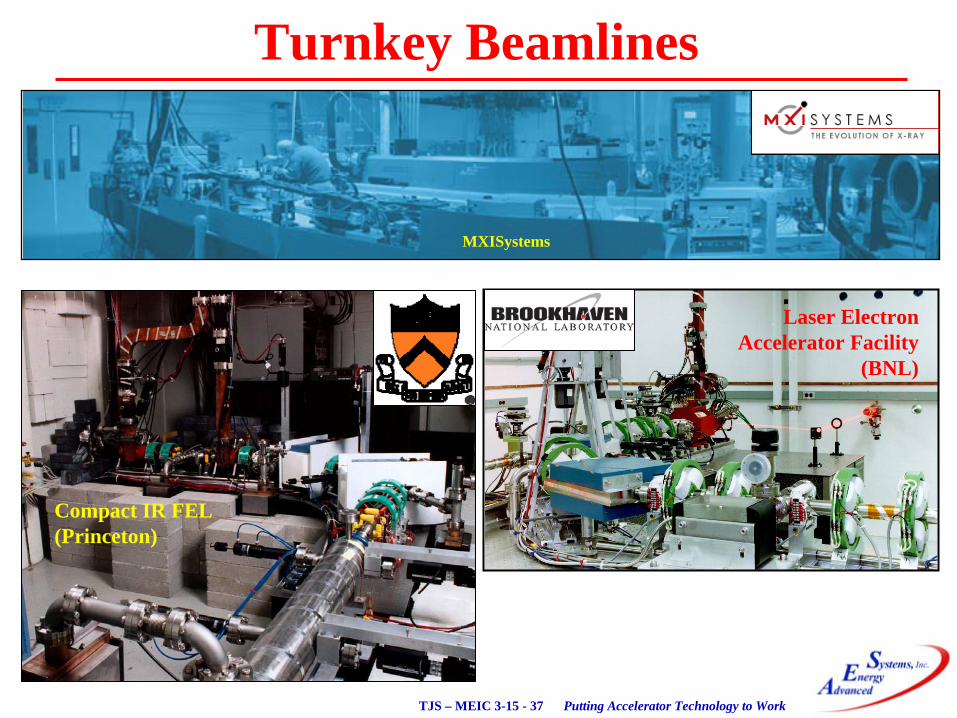
Turnkey Beamlines
MXISystems
Laser ElectronAccelerator Facility
(BNL)
Compact IR FEL(Princeton)
Putting Accelerator Technology to WorkTJS – MEIC 3-15 - 38
AES ContactsTom Schultheiss
Technical Specialist
(631) 345-6264 x [email protected]
http://www.aesys.net
Alan ToddC0-President and
Chief Scientist
(631) [email protected]
http://www.aesys.net
John RathkeCo-President and
Chief Engineer
(631) [email protected]
http://www.aesys.net
Hans BluemPrincipal Investigator and
Staff Scientist
(609) [email protected]
http://www.aesys.net