advanced collimators for future colliders or status of r&d...
TRANSCRIPT
Advanced Collimators for Future Collidersor
Status of R&D on Collimators for e+e- LCs & HL-LHC
12 November 2014CAS/USPAS Joint Accelerator School
Newport Beach, CAT. Markiewicz/SLAC
HEP Experimentalist• Planar Wire Chambers for Muon Beam at FNAL• UA1 Central Drift Chamber at CERN SppS Collider• SLD Central Drift Chamber (CDC) at SLAC
Sensitivity of CDC to HV trips and SLD Muon Backgrounds• Machine Instabilities [Marc Ross talks] affecting beam orbit or energy
causing burnt collimator coatings, muon production and massive synchrotron radiation flux in strongly focusing final quad system.
Design NLC/ILC collimation system for robustness and minimal wakes• Tapered, coated, robust spoilers & “consumable” spoilers• High power issues from disrupted beams after beam-beam interaction• Muon systems
Adapt “rotatable” concept to LHC High Energy/ High Power beamsExposed to gamut of R&D for next generation LHC collimation
• Development of robust low impedance collimators (A. Bertarelli talks)• Hollow Electron Beams developed at FNAL• Application of crystals to collimation
My Personal Path Into Collimation
Slide n° 2 / 70
LHC Collimation & Upgrade Specification Working Groups• R. Assmann, A. Bertarelli, S. Redaelli et al
US LHC Accelerator Research Program (LARP)• High Power Rotatable Collimator-TWM et al at SLAC• Hollow Electron Beam Collimation- G. Stancari et al at Fermilab
H8/UA9 Collaborations (Crystal Collimation at H8 & SPS/LHC)• Proton Collimation: W. Scandale, D. Mirarchi, et al.
SLAC T513 Crystal Collimation Experiment• Electron Collimation: U. Wienands et al
ILC & predecessor organizations (SLC, NLC, ..) at SLAC• Wakefield optimized spoilers for high intensity e- beams- P.Tenenbaum• Consumable solid and liquid metal collimators- J. Frisch et al• Muon Spoilers-L. Keller et al
Credits and Acknowledgements
Slide n° 3 / 70
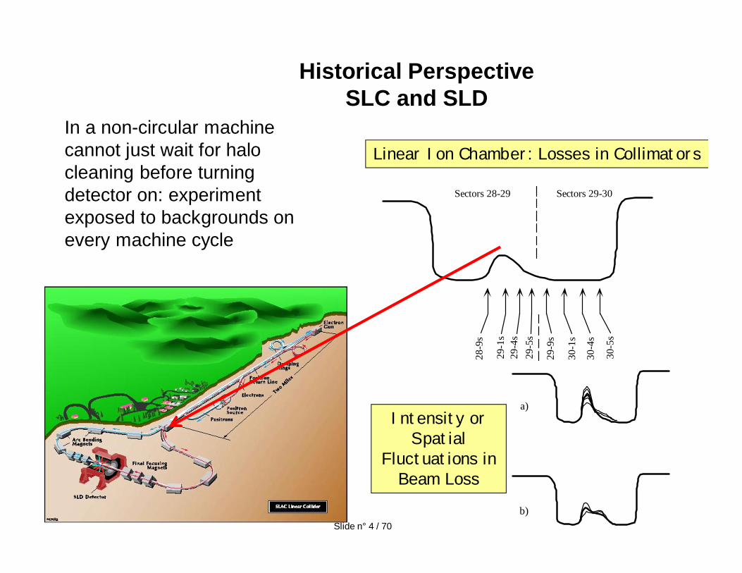
Historical PerspectiveSLC and SLD
Sectors 28-29 Sectors 29-30
28-9
s
29-1
s29
-4s
29-5
s
29-9
s
30-1
s
30-4
s
30-5
s
a)
b)
Linear Ion Chamber: Losses in Collimators
Intensity or Spatial
Fluctuations in Beam Loss
In a non-circular machine cannot just wait for halo cleaning before turning detector on: experiment exposed to backgrounds on every machine cycle
Slide n° 4 / 70
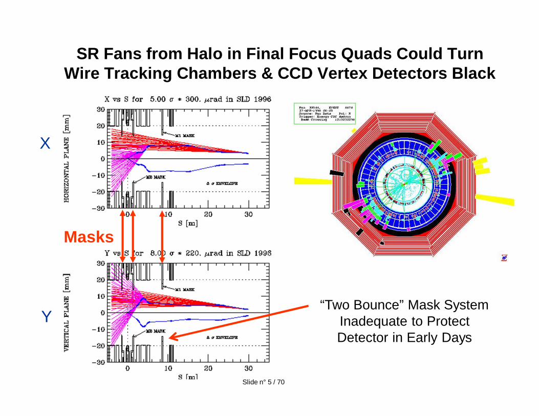
SR Fans from Halo in Final Focus Quads Could Turn Wire Tracking Chambers & CCD Vertex Detectors Black
“Two Bounce” Mask System Inadequate to Protect Detector in Early Days
X
Y
Masks
Slide n° 5 / 70
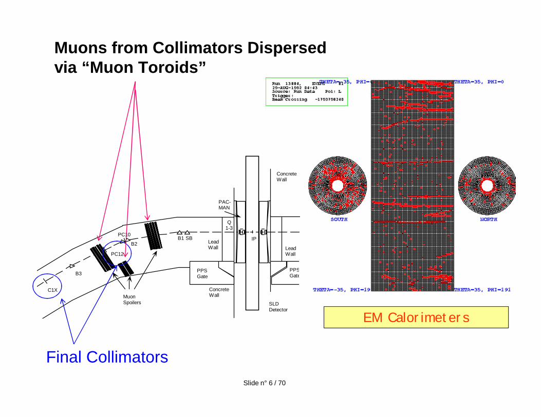
Muons from Collimators Dispersed via “Muon Toroids”
EM Calorimeters2
MuonSpoilers
LeadWall
C1X
B3
PC10
B2B1 SB
Q1-3
PC12
SLDDetector
ConcreteWall
IP
PAC-MAN
PPSGate
PPSGate
ConcreteWall
LeadWall
Slide n° 6 / 70
Final Collimators
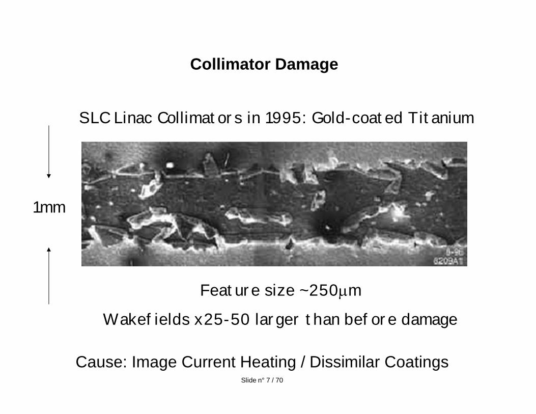
Collimator Damage
1mm
SLC Linac Collimators in 1995: Gold-coated Titanium
Feature size ~250 m
Wakefields x25-50 larger than before damage
Cause: Image Current Heating / Dissimilar Coatings Slide n° 7 / 70

Collimation Apertures must be set so “NO” halo can make SR that hits anything in detector• Exit aperture of calorimeter closest to beam sets this “depth”
Beam Intensity requires system of “Spoilers” and “Absorbers”• Two stage collimation, in LHC terminology
Indestructible spoilers require very large beta functions at the spoilers which leads to position on vibration tolerances equivalent to the final focusing doublet magnetsIf you don’t expect many beam faults may be a good idea to build a system where collimator can be damaged a few times and still function in exchange for much looser tolerances
• Investigation of “Consumable” and “Renewable” Spoilers for NLCLong interbunch spacing of ILC gives time to dump back part of bunch train and relaxes need for “renewable” design
Applying SLC Lessons Learned to NLC/ILC Designs
Slide n° 8 / 70
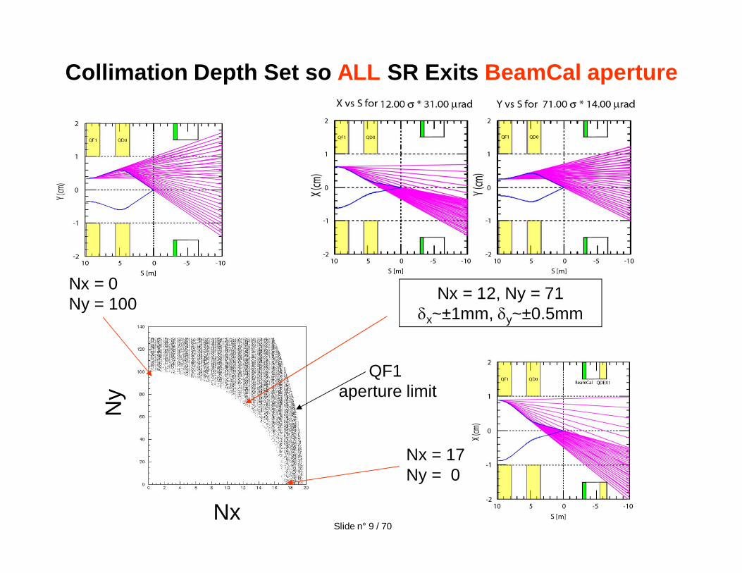
Collimation Depth Set so ALL SR Exits BeamCal aperture
Ny
Nx
Nx = 17Ny = 0
Nx = 0Ny = 100
QF1 aperture limit
Nx = 12, Ny = 71x~±1mm, y~±0.5mm
Slide n° 9 / 70
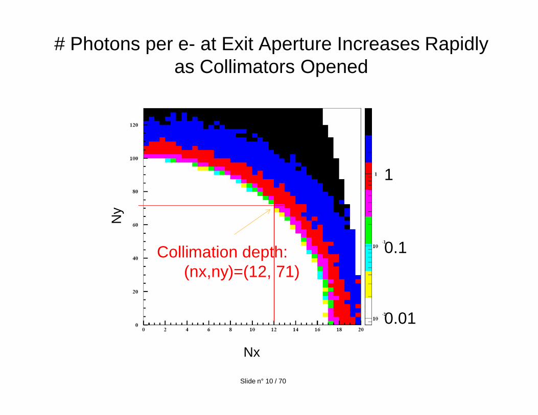
# Photons per e- at Exit Aperture Increases Rapidlyas Collimators Opened
Ny
Nx
Collimation depth: (nx,ny)=(12, 71)
0.01
0.1
1
Slide n° 10 / 70
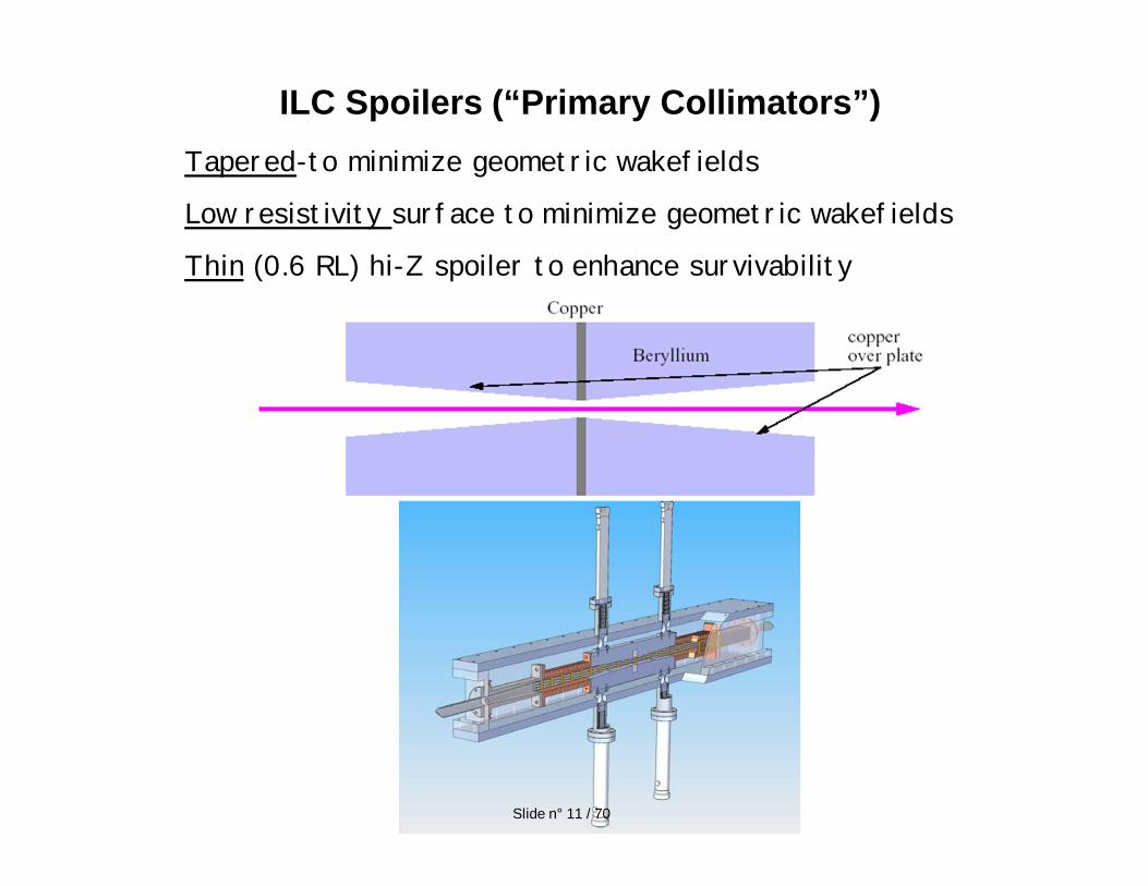
ILC Spoilers (“Primary Collimators”)Tapered-to minimize geometric wakefields
Low resistivity surface to minimize geometric wakefields
Thin (0.6 RL) hi-Z spoiler to enhance survivability
Slide n° 11 / 70
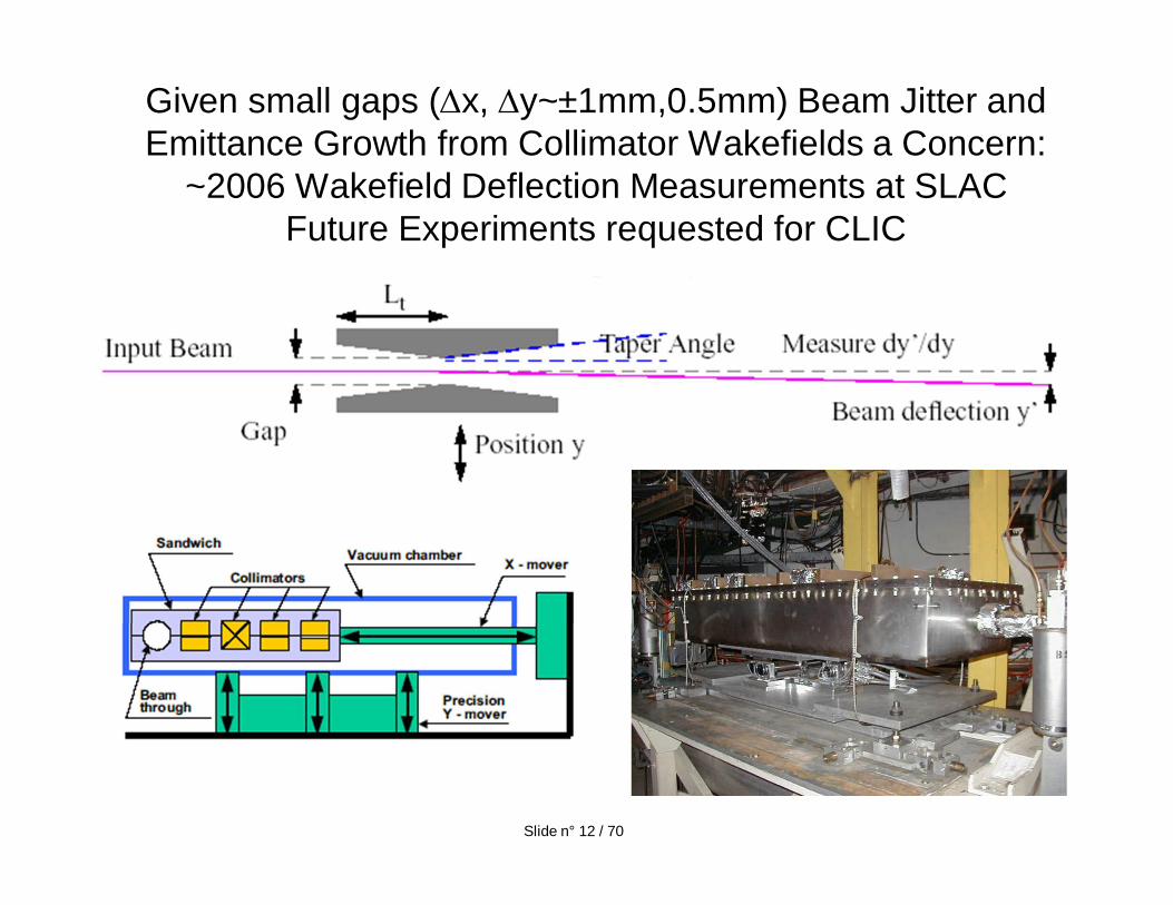
Given small gaps ( x, y~±1mm,0.5mm) Beam Jitter and Emittance Growth from Collimator Wakefields a Concern:
~2006 Wakefield Deflection Measurements at SLAC Future Experiments requested for CLIC
Slide n° 12 / 70
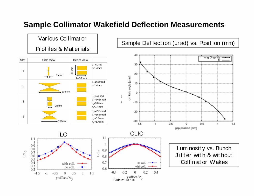
Sample Collimator Wakefield Deflection MeasurementsVarious Collimator
Profiles & Materials
=298mrad=168mrad
r1 =3.8mmr2 =1.4mm
4
1= /2 rad
2=168mradr1=3.8mmr2=1.4mm
3
168mradr=1.4mm2
= /2radr=1.4mm
1
Beam viewSide viewSlot
h=38 mm
38 m
m7 mm
208mm
28mm
159mm
ILC CLIC
Sample Deflection (urad) vs. Position (mm)
Luminosity vs. Bunch Jitter with & without
Collimator Wakes
Slide n° 13 / 70
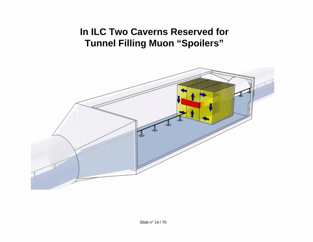
In ILC Two Caverns Reserved for Tunnel Filling Muon “Spoilers”
Slide n° 14 / 70
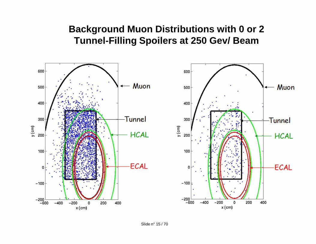
Background Muon Distributions with 0 or 2 Tunnel-Filling Spoilers at 250 Gev/ Beam
Slide n° 15 / 70
16
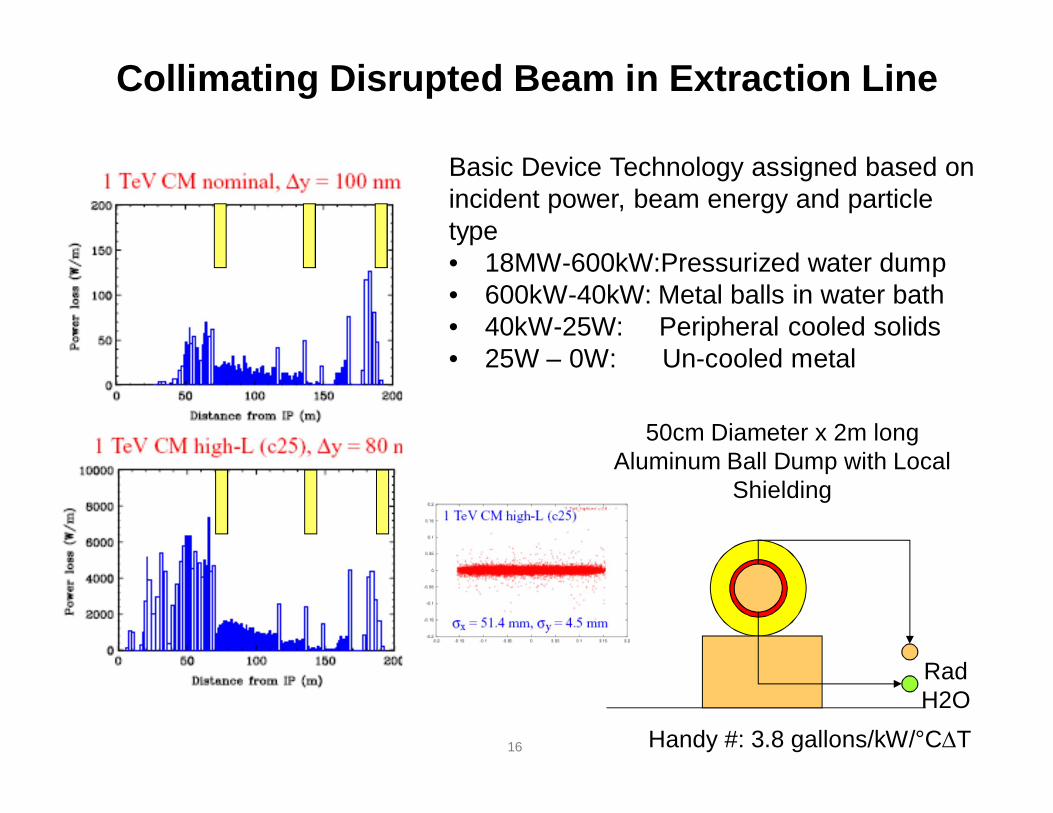
Collimating Disrupted Beam in Extraction Line
Basic Device Technology assigned based on incident power, beam energy and particle type• 18MW-600kW:Pressurized water dump• 600kW-40kW: Metal balls in water bath• 40kW-25W: Peripheral cooled solids• 25W – 0W: Un-cooled metal
50cm Diameter x 2m long Aluminum Ball Dump with Local
Shielding
RadH2O
Handy #: 3.8 gallons/kW/°C T
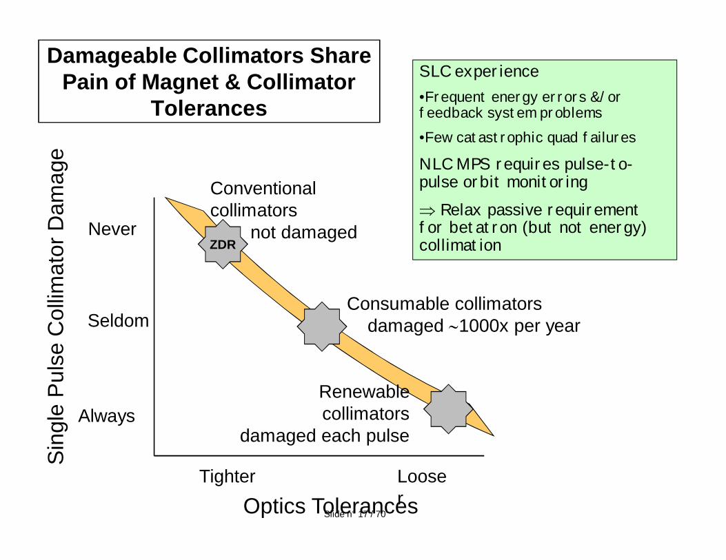
Damageable Collimators Share Pain of Magnet & Collimator
Tolerances
Tighter LooserOptics Tolerances
Never
Always
Seldom
Sin
gle
Pul
se C
ollim
ator
Dam
age
ZDR
Consumable collimatorsdamaged 1000x per year
Renewable collimators
damaged each pulse
Conventional collimators
not damaged
SLC experience•Frequent energy errors &/or feedback system problems •Few catastrophic quad failures
NLC MPS requires pulse-to-pulse orbit monitoring
Relax passive requirement for betatron (but not energy) collimation
Slide n° 17 / 70
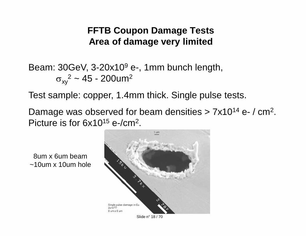
FFTB Coupon Damage TestsArea of damage very limited
Beam: 30GeV, 3-20x109 e-, 1mm bunch length, xy
2 ~ 45 - 200um2
Test sample: copper, 1.4mm thick. Single pulse tests.
Damage was observed for beam densities > 7x10¹⁴ e- / cm2. Picture is for 6x10¹⁵ e-/cm2.
8um x 6um beam~10um x 10um hole
Slide n° 18 / 70
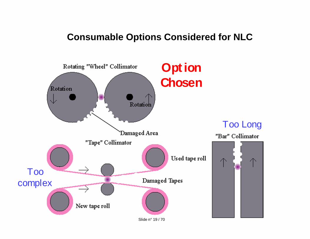
Consumable Options Considered for NLC
Too Long
Too complex
Option Chosen
Slide n° 19 / 70
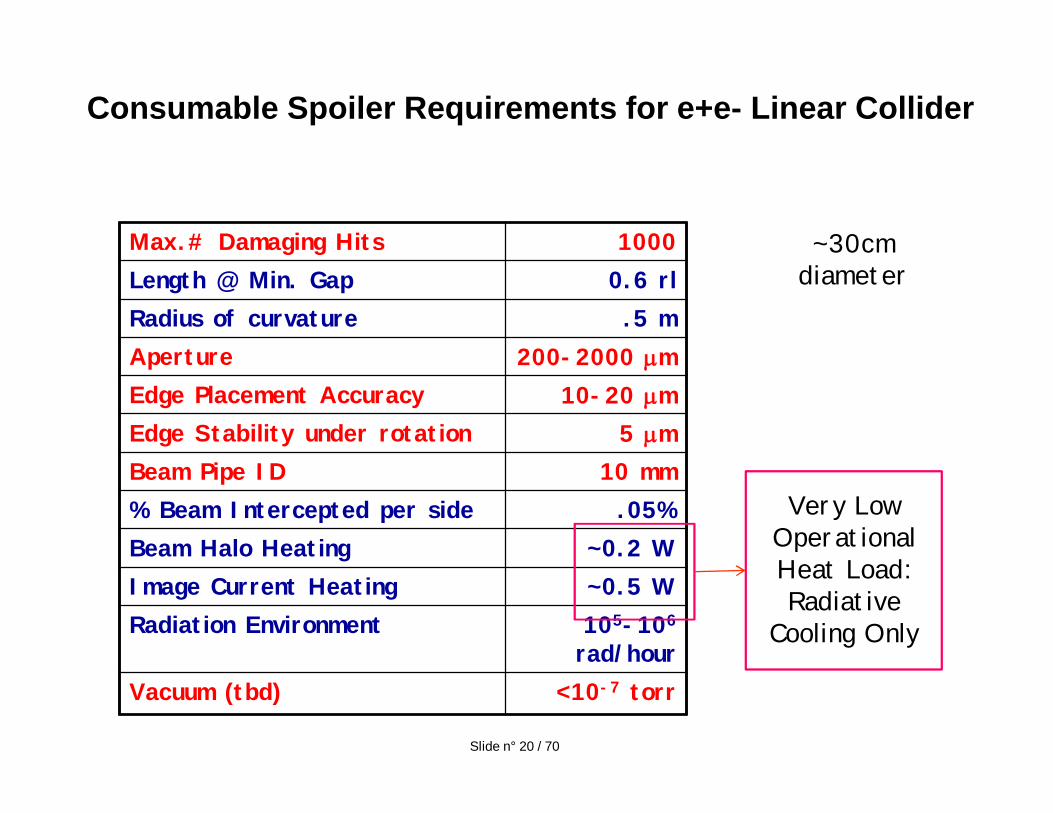
Consumable Spoiler Requirements for e+e- Linear Collider
Max.# Damaging Hits 1000Length @ Min. Gap 0.6 rlRadius of curvature .5 mAperture 200-2000 mEdge Placement Accuracy 10-20 mEdge Stability under rotation 5 mBeam Pipe ID 10 mm% Beam Intercepted per side .05%Beam Halo Heating ~0.2 WImage Current Heating ~0.5 WRadiation Environment 105-106
rad/hourVacuum (tbd) <10-7 torr
~30cm diameter
Very Low Operational Heat Load: Radiative
Cooling Only
Slide n° 20 / 70
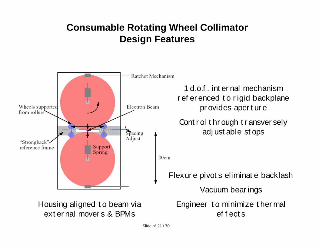
Consumable Rotating Wheel Collimator Design Features
1 d.o.f. internal mechanism referenced to rigid backplane
provides aperture
Control through transversely adjustable stops
Housing aligned to beam via external movers & BPMs
Flexure pivots eliminate backlash
Vacuum bearings
Engineer to minimize thermal effects
Slide n° 21 / 70
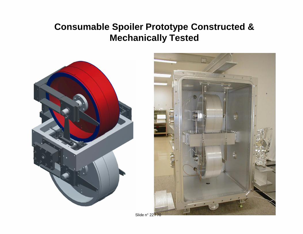
Consumable Spoiler Prototype Constructed & Mechanically Tested
Slide n° 22 / 70
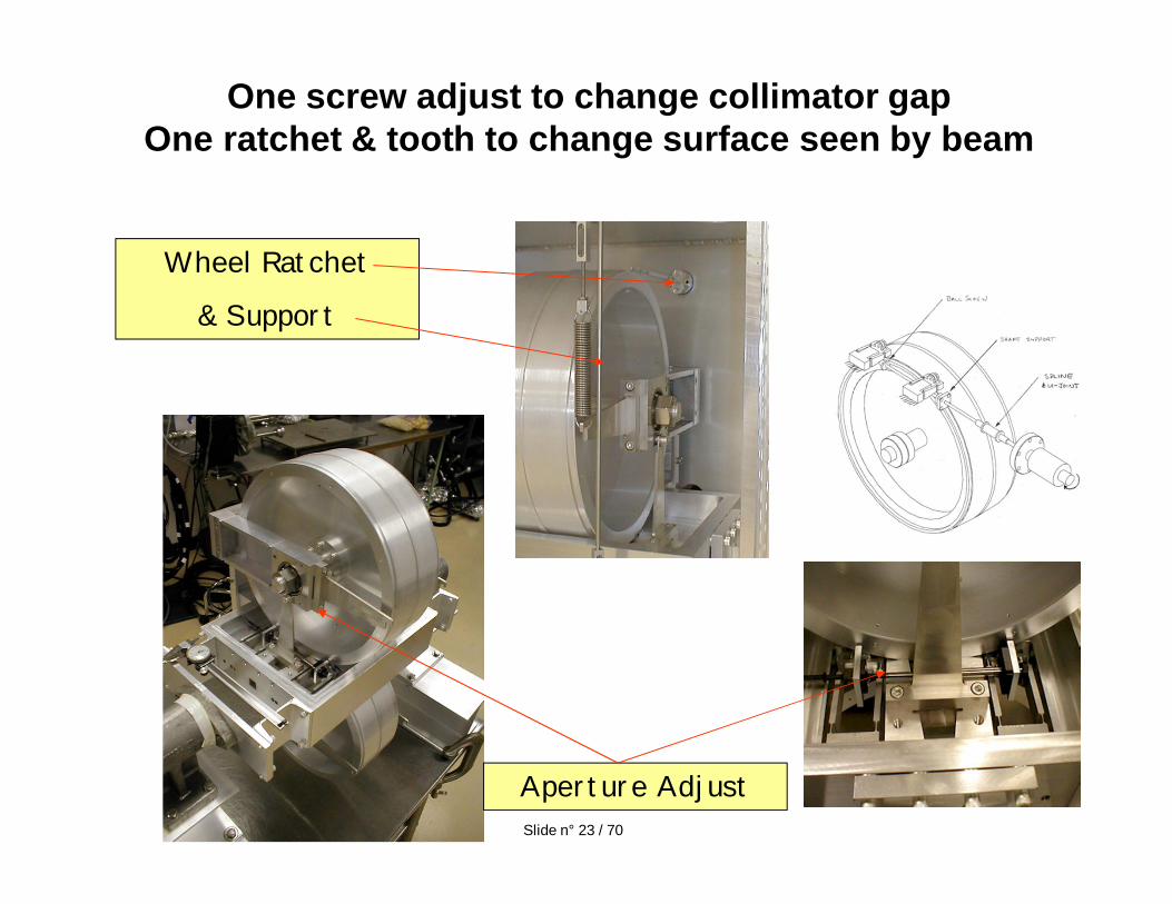
One screw adjust to change collimator gapOne ratchet & tooth to change surface seen by beam
Aperture Adjust
Wheel Ratchet
& Support
Slide n° 23 / 70
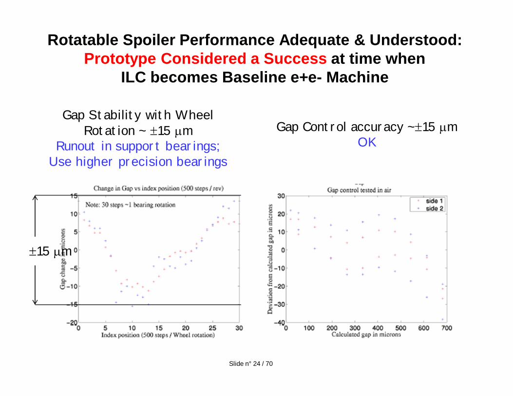
Rotatable Spoiler Performance Adequate & Understood: Prototype Considered a Success at time when
ILC becomes Baseline e+e- Machine
Gap Stability with Wheel Rotation ~ 15 m
Runout in support bearings; Use higher precision bearings
Gap Control accuracy ~ 15 mOK
Slide n° 24 / 70
15 m
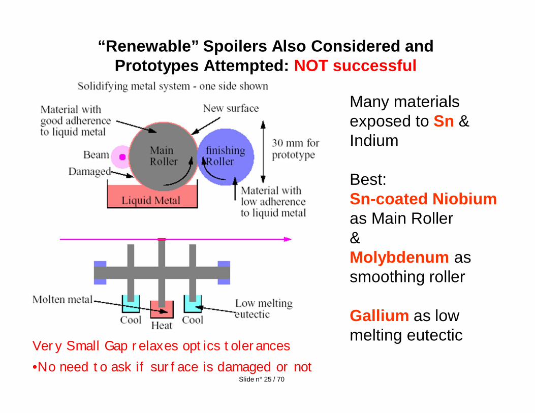
“Renewable” Spoilers Also Considered and Prototypes Attempted: NOT successful
Very Small Gap relaxes optics tolerances •No need to ask if surface is damaged or not
Many materials exposed to Sn & Indium
Best:Sn-coated Niobium as Main Roller&Molybdenum as smoothing roller
Gallium as low melting eutectic
Slide n° 25 / 70
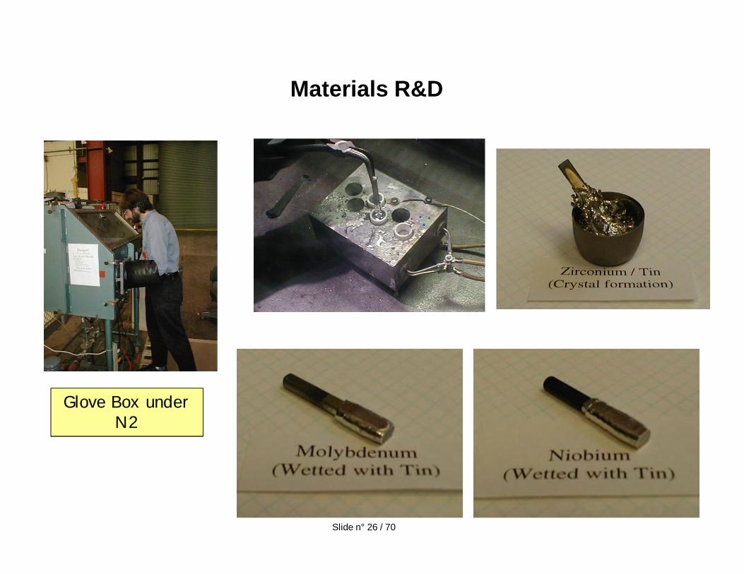
Materials R&D
Glove Box under N2
Slide n° 26 / 70
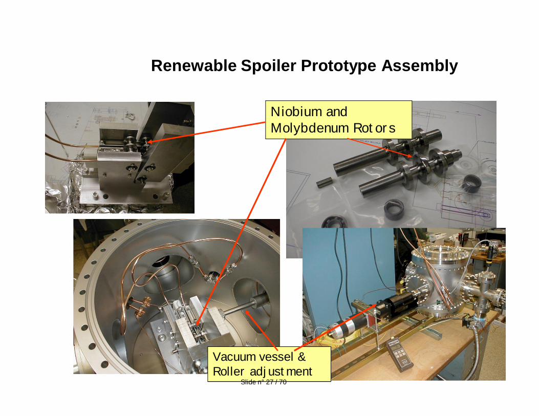
Renewable Spoiler Prototype Assembly
Niobium and Molybdenum Rotors
Vacuum vessel & Roller adjustment
Slide n° 27 / 70
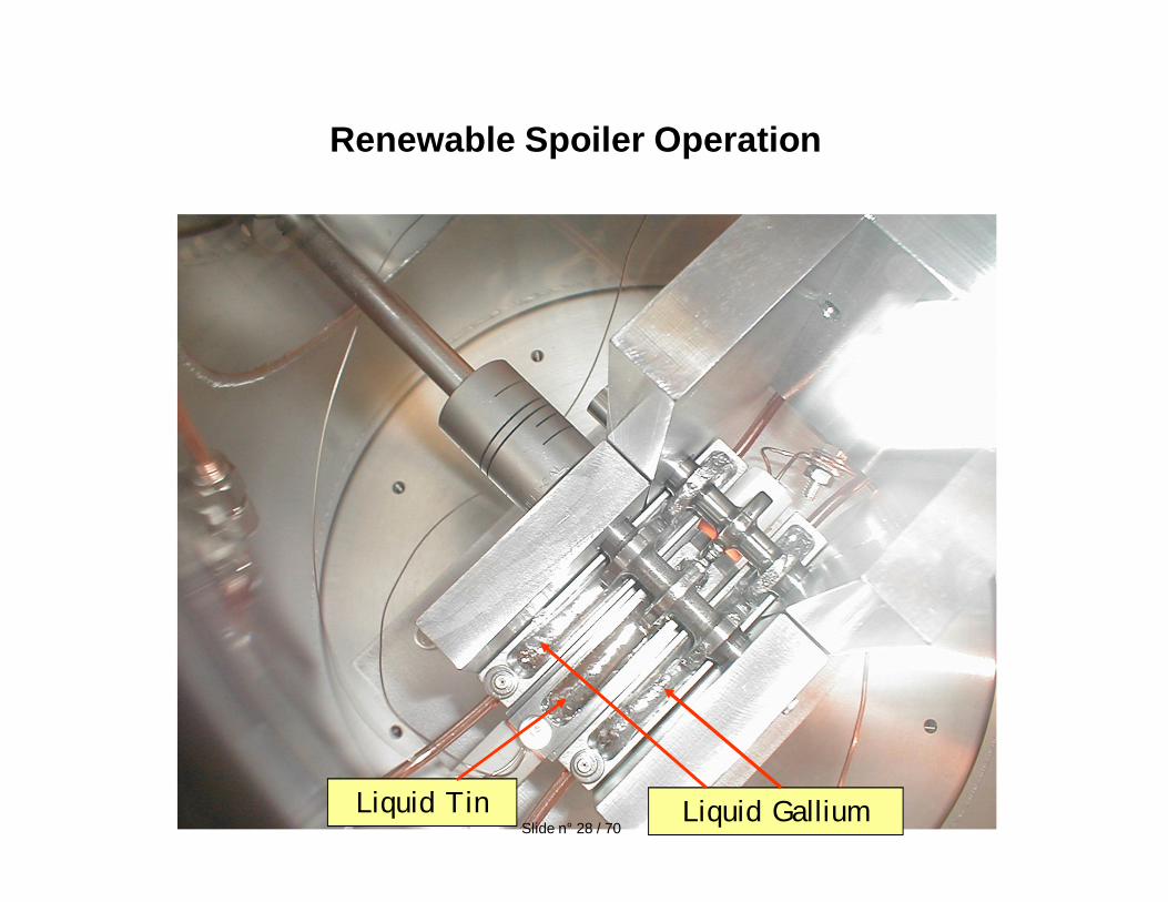
Renewable Spoiler Operation
Liquid Tin Liquid GalliumSlide n° 28 / 70
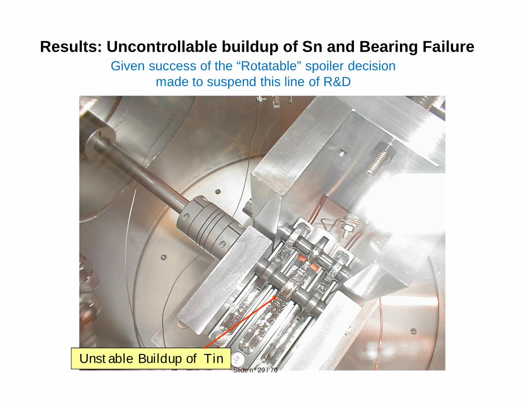
Results: Uncontrollable buildup of Sn and Bearing Failure
Unstable Buildup of Tin
Given success of the “Rotatable” spoiler decision made to suspend this line of R&D
Slide n° 29 / 70
Near term R&D for:• BPM equipped collimators• Secondary collimators based on the Mo-Gr material discussed by
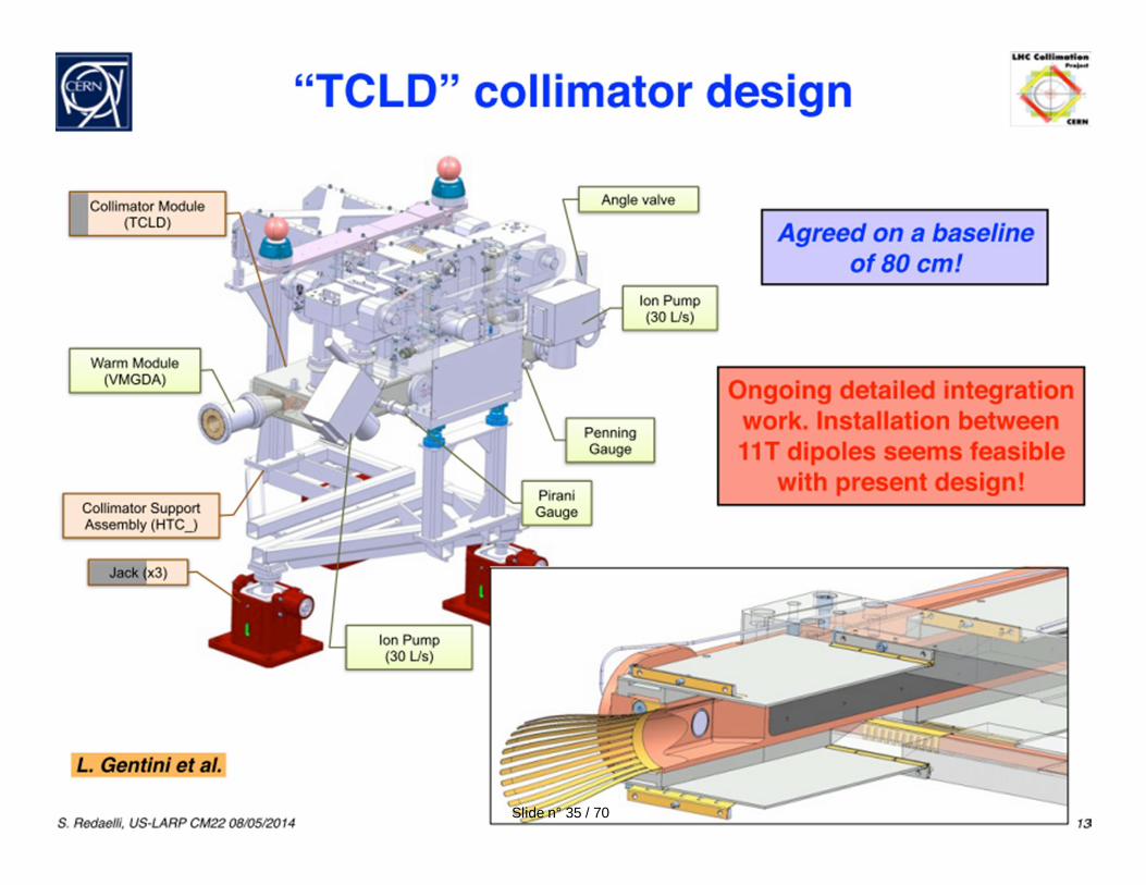
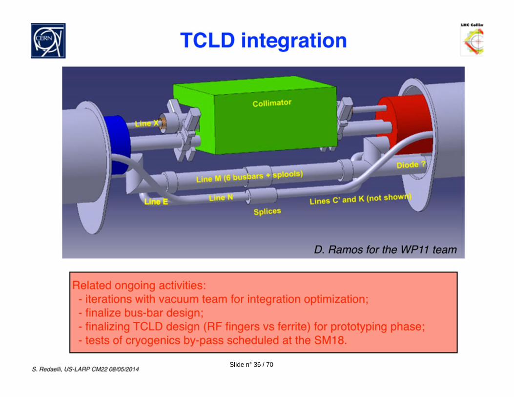
Alessandro Bertarelli• Collimators to be inserted in the cold areas of LHC after new shorter
11 Tesla Nb3Sn dipoles are inserted to make space
Next to Near Term R&D:• LARP “Rotatable” Collimator for LHC• Hollow Electron Lens Beam Scraper• Crystals as primary collimators
LHC Collimation R&D
Slide n° 30 / 70
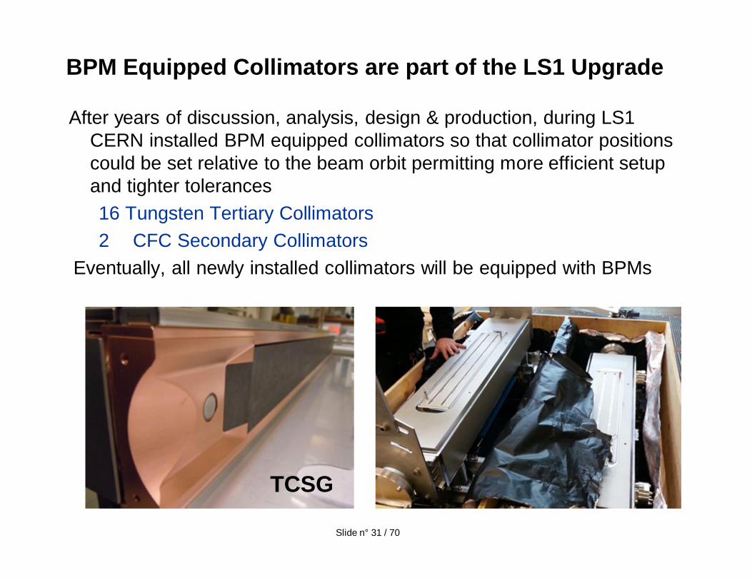
After years of discussion, analysis, design & production, during LS1 CERN installed BPM equipped collimators so that collimator positions could be set relative to the beam orbit permitting more efficient setup and tighter tolerances16 Tungsten Tertiary Collimators2 CFC Secondary Collimators
Eventually, all newly installed collimators will be equipped with BPMs
BPM Equipped Collimators are part of the LS1 Upgrade
TCSG
Slide n° 31 / 70
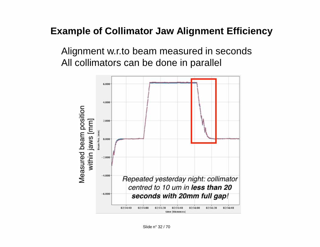
Example of Collimator Jaw Alignment Efficiency
Slide n° 32 / 70
Alignment w.r.to beam measured in secondsAll collimators can be done in parallel
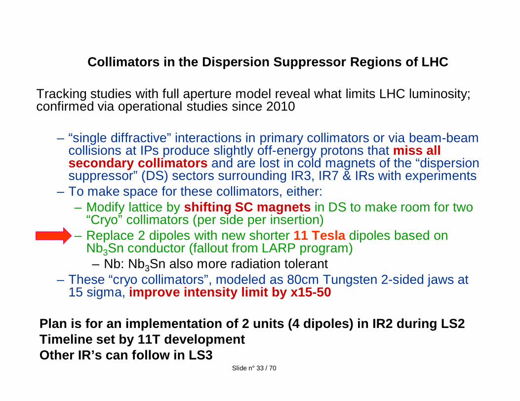
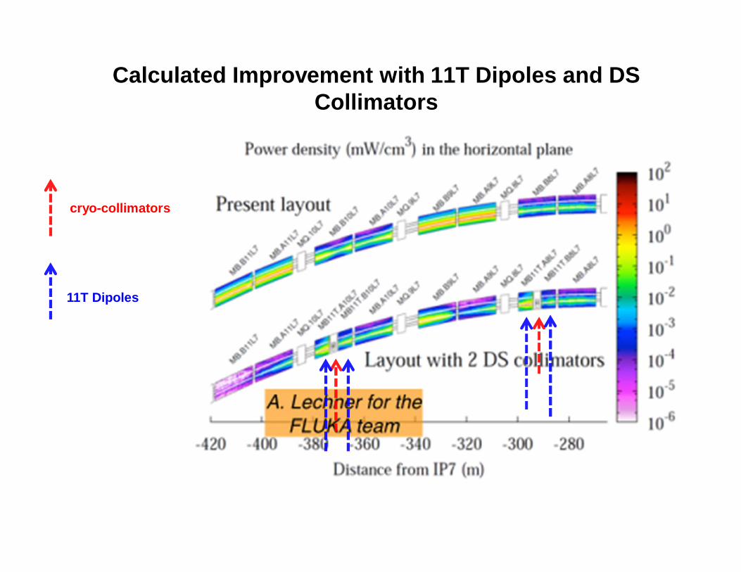
Collimators in the Dispersion Suppressor Regions of LHC
Tracking studies with full aperture model reveal what limits LHC luminosity; confirmed via operational studies since 2010
– “single diffractive” interactions in primary collimators or via beam-beam collisions at IPs produce slightly off-energy protons that miss all secondary collimators and are lost in cold magnets of the “dispersion suppressor” (DS) sectors surrounding IR3, IR7 & IRs with experiments
– To make space for these collimators, either:– Modify lattice by shifting SC magnets in DS to make room for two
“Cryo” collimators (per side per insertion)– Replace 2 dipoles with new shorter 11 Tesla dipoles based on
Nb3Sn conductor (fallout from LARP program)– Nb: Nb3Sn also more radiation tolerant
– These “cryo collimators”, modeled as 80cm Tungsten 2-sided jaws at 15 sigma, improve intensity limit by x15-50
Plan is for an implementation of 2 units (4 dipoles) in IR2 during LS2Timeline set by 11T developmentOther IR’s can follow in LS3
Slide n° 33 / 70
cryo-collimators
Calculated Improvement with 11T Dipoles and DS Collimators
11T Dipoles
Slide n° 35 / 70
Slide n° 36 / 70
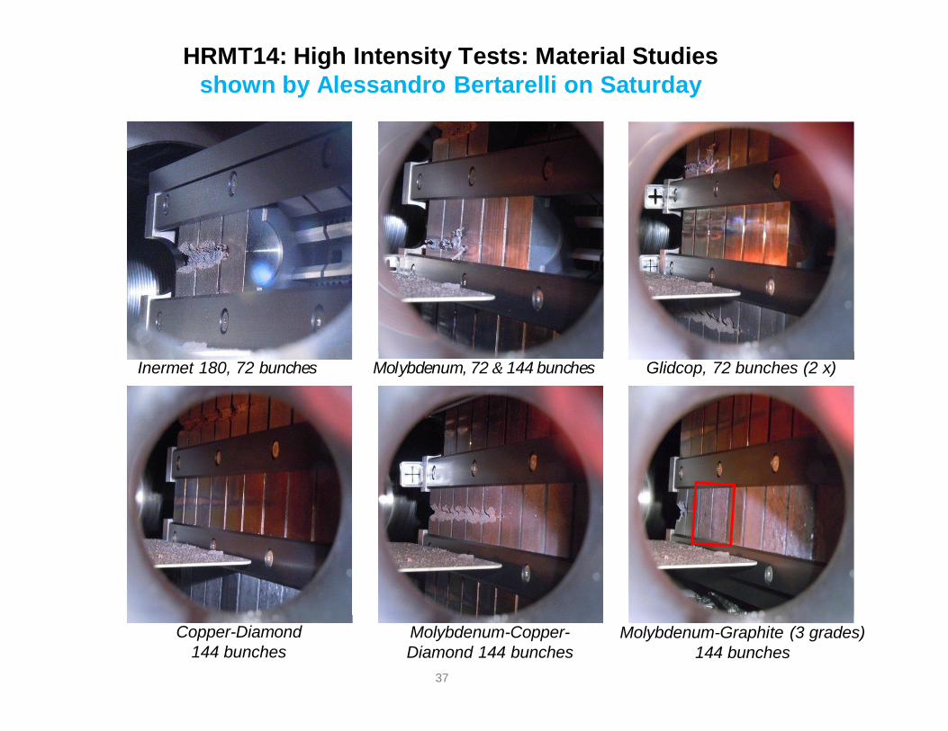
HRMT14: High Intensity Tests: Material Studiesshown by Alessandro Bertarelli on Saturday
Inermet 180, 72 bunches Molybdenum, 72 144 bunches Glidcop, 72 bunches (2 x)
Copper-Diamond144 bunches
Molybdenum-Copper-Diamond 144 bunches
Molybdenum-Graphite (3 grades) 144 bunches
37
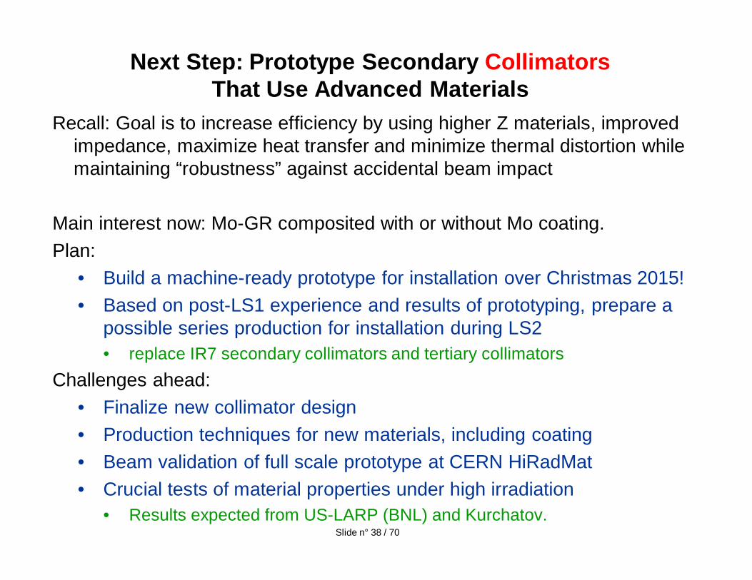
Recall: Goal is to increase efficiency by using higher Z materials, improved impedance, maximize heat transfer and minimize thermal distortion while maintaining “robustness” against accidental beam impact
Main interest now: Mo-GR composited with or without Mo coating.Plan:
• Build a machine-ready prototype for installation over Christmas 2015!• Based on post-LS1 experience and results of prototyping, prepare a
possible series production for installation during LS2• replace IR7 secondary collimators and tertiary collimators
Challenges ahead:• Finalize new collimator design• Production techniques for new materials, including coating• Beam validation of full scale prototype at CERN HiRadMat• Crucial tests of material properties under high irradiation
• Results expected from US-LARP (BNL) and Kurchatov.
Next Step: Prototype Secondary CollimatorsThat Use Advanced Materials
Slide n° 38 / 70
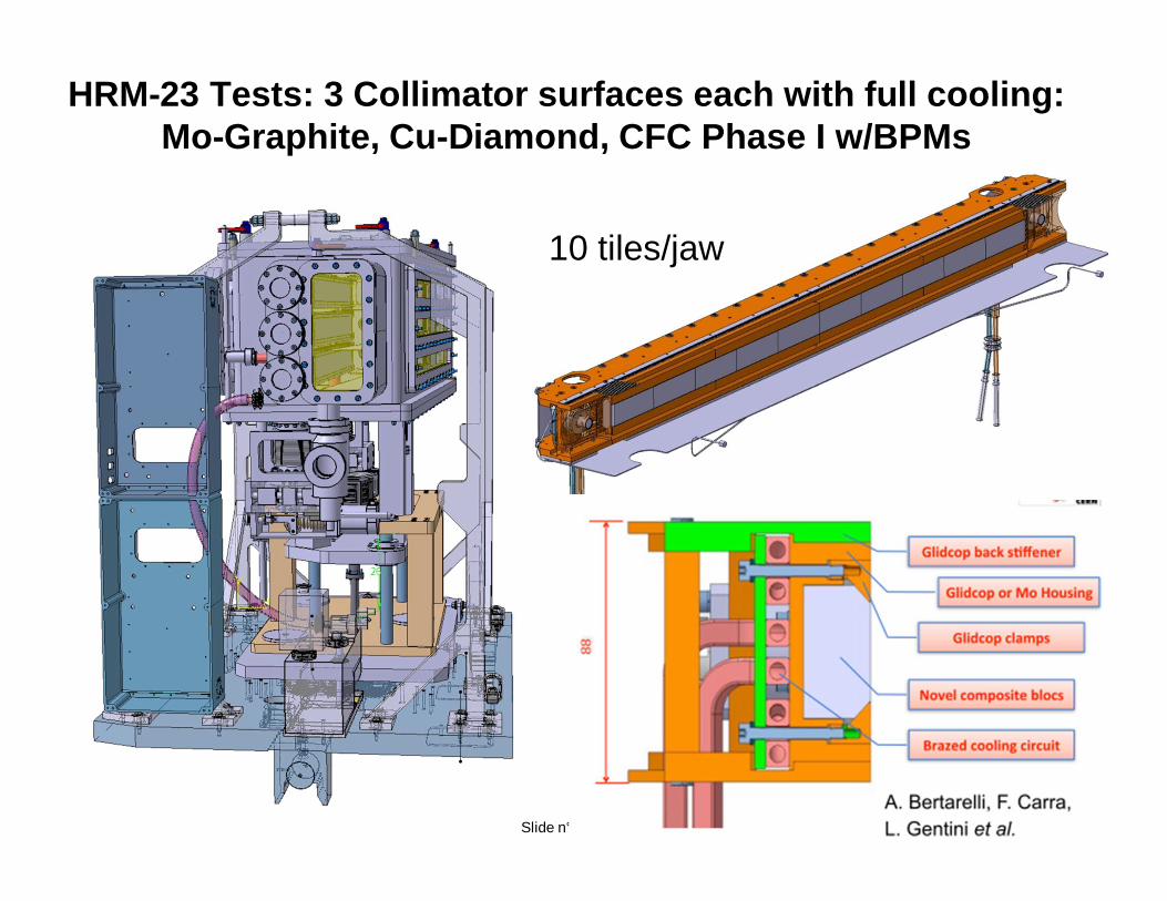
HRM-23 Tests: 3 Collimator surfaces each with full cooling: Mo-Graphite, Cu-Diamond, CFC Phase I w/BPMs
10 tiles/jaw
Slide n° 39 / 70
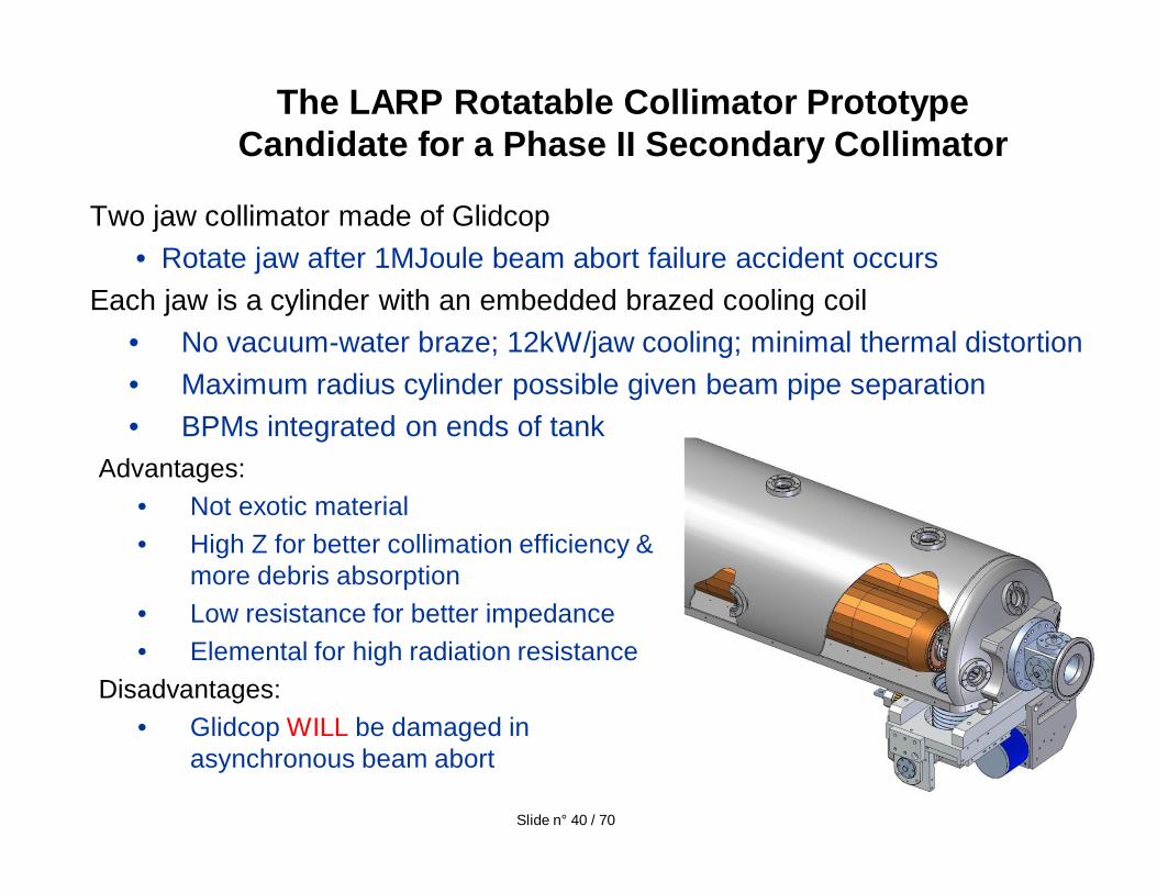
Two jaw collimator made of Glidcop• Rotate jaw after 1MJoule beam abort failure accident occurs
Each jaw is a cylinder with an embedded brazed cooling coil• No vacuum-water braze; 12kW/jaw cooling; minimal thermal distortion• Maximum radius cylinder possible given beam pipe separation• BPMs integrated on ends of tank
The LARP Rotatable Collimator PrototypeCandidate for a Phase II Secondary Collimator
Advantages:• Not exotic material• High Z for better collimation efficiency &
more debris absorption• Low resistance for better impedance• Elemental for high radiation resistance
Disadvantages:• Glidcop WILL be damaged in
asynchronous beam abort
Slide n° 40 / 70
Initial LHC Collimation Plan
Decision made in 2003 to install a collimation system based on CARBON jaws which would survive impact of 8 full LHC bunches (1 Mjoule) if abort kicker misfires with respect to abort gap (expected rate < 1x/year)– Called Phase I because, while “robust”
• Impedance might limit maximum luminosity to ~25% nominal• Halo “Cleaning efficiency” not adequate for nominal or ultimate luminosity• Radiation hardness not equal to that of metals
– Plug ready slots left behind each 1m secondary for a PHASE II device• SLAC approached in 2004 to adapt the “rotatable” NLC collimator design to
LHC & to produce a plug-compatible prototype that would fit between existing beam pipes– Metal (eventually choose Glidcop (Cu+0.15% Al))– When collimation surface damaged, rotate to expose fresh surface to beam– Challenges:
» Water cooled for 1 hour beam lifetime loss rates» 90kW beam loss; 12kW per jaw absorbed in Glidcop
» Maintain 25um jaw flatness during operation » Injection transients of 450kW for 10 sec -> 60kW per jaw absorbed
» Limit local and global damage during abort accident; vacuum; impedance…..Slide n° 41 / 70
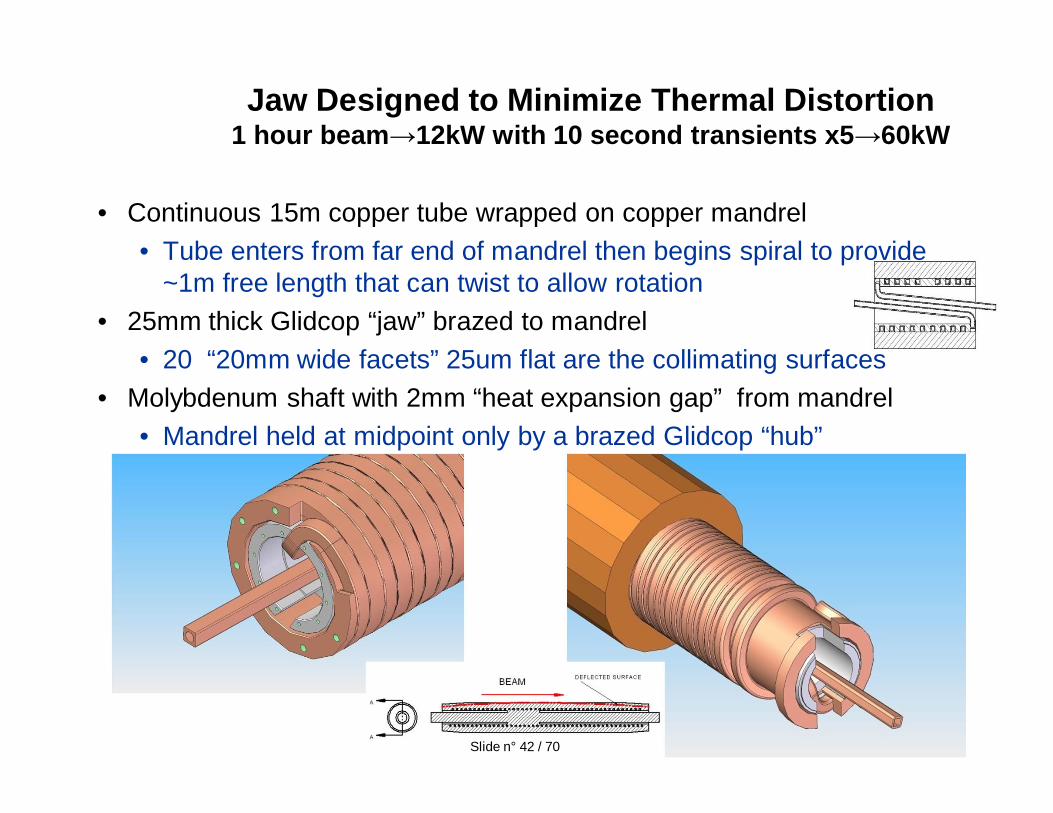
• Continuous 15m copper tube wrapped on copper mandrel• Tube enters from far end of mandrel then begins spiral to provide
~1m free length that can twist to allow rotation• 25mm thick Glidcop “jaw” brazed to mandrel
• 20 “20mm wide facets” 25um flat are the collimating surfaces• Molybdenum shaft with 2mm “heat expansion gap” from mandrel
• Mandrel held at midpoint only by a brazed Glidcop “hub”
Jaw Designed to Minimize Thermal Distortion1 hour beam 12kW with 10 second transients x5 60kW
Slide n° 42 / 70
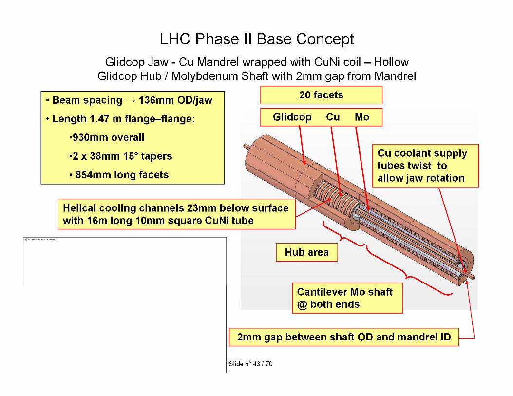
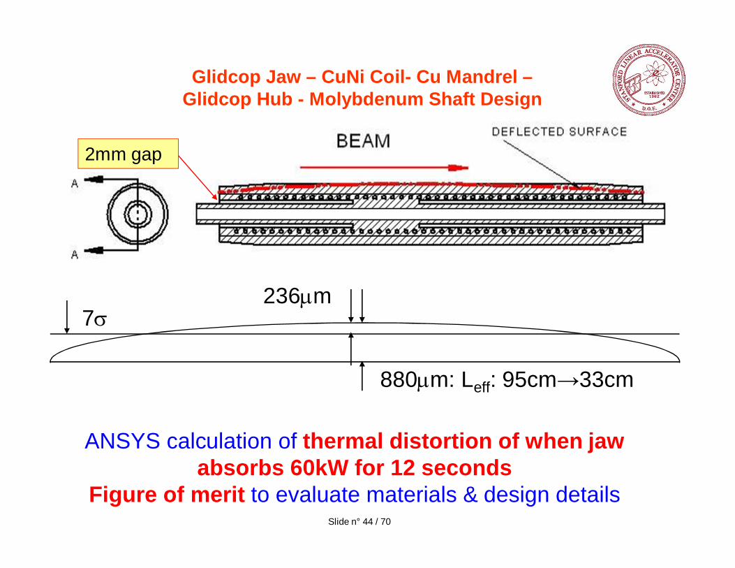
Glidcop Jaw – CuNi Coil- Cu Mandrel –Glidcop Hub - Molybdenum Shaft Design
236 m
880 m: Leff: 95cm 33cm
7
ANSYS calculation of thermal distortion of when jaw absorbs 60kW for 12 seconds
Figure of merit to evaluate materials & design details
2mm gap
Slide n° 44 / 70
ATLAS Forum - 07 November 2007 LHC Collimation - T. MarkiewiczSlide n° 45 / 68
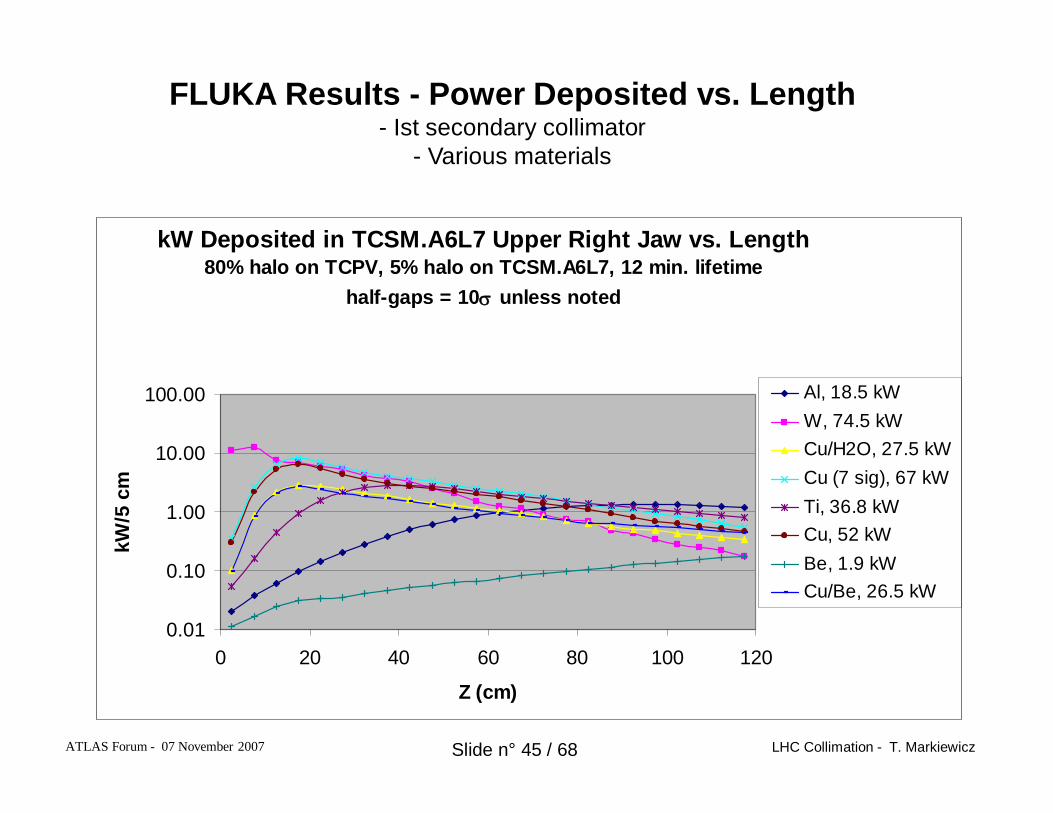
FLUKA Results - Power Deposited vs. Length- Ist secondary collimator
- Various materials
4 x 10¹¹ p/s lost
kW Deposited in TCSM.A6L7 Upper Right Jaw vs. Length80% halo on TCPV, 5% halo on TCSM.A6L7, 12 min. lifetime
half-gaps = 10 unless noted
0.01
0.10
1.00
10.00
100.00
0 20 40 60 80 100 120
Z (cm)
kW/5
cm
Al, 18.5 kWW, 74.5 kWCu/H2O, 27.5 kWCu (7 sig), 67 kWTi, 36.8 kWCu, 52 kWBe, 1.9 kWCu/Be, 26.5 kW
ATLAS Forum - 07 November 2007 LHC Collimation - T. MarkiewiczSlide n° 46 / 68
material
cooling arc (deg)
power (kW) per jaw
Tmax ( C)
defl (um) Tmax water side( C)
max flux (W/m^2)
power (kW)
Tmax ( C)
defl (um) Tmax water side( C)
max flux (W/m^2)
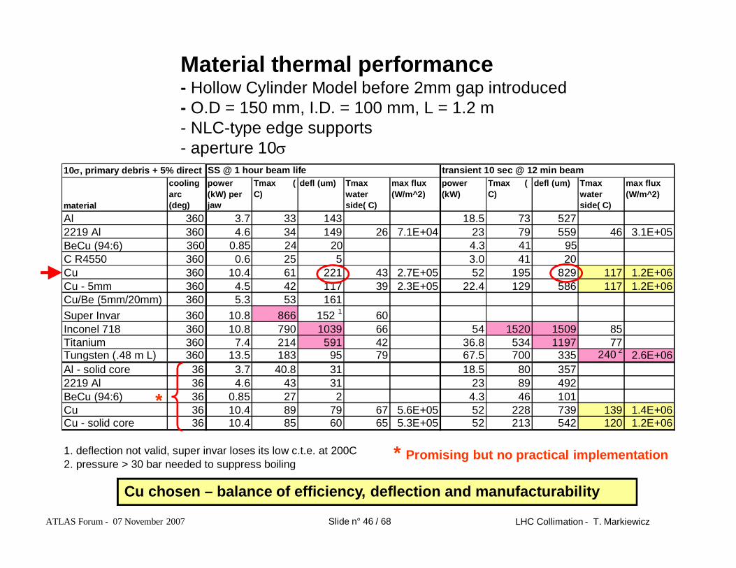
Al 360 3.7 33 143 18.5 73 5272219 Al 360 4.6 34 149 26 7.1E+04 23 79 559 46 3.1E+05BeCu (94:6) 360 0.85 24 20 4.3 41 95C R4550 360 0.6 25 5 3.0 41 20Cu 360 10.4 61 221 43 2.7E+05 52 195 829 117 1.2E+06Cu - 5mm 360 4.5 42 117 39 2.3E+05 22.4 129 586 117 1.2E+06Cu/Be (5mm/20mm) 360 5.3 53 161Super Invar 360 10.8 866 152 1 60Inconel 718 360 10.8 790 1039 66 54 1520 1509 85Titanium 360 7.4 214 591 42 36.8 534 1197 77Tungsten (.48 m L) 360 13.5 183 95 79 67.5 700 335 240 2 2.6E+06Al - solid core 36 3.7 40.8 31 18.5 80 3572219 Al 36 4.6 43 31 23 89 492BeCu (94:6) 36 0.85 27 2 4.3 46 101Cu 36 10.4 89 79 67 5.6E+05 52 228 739 139 1.4E+06Cu - solid core 36 10.4 85 60 65 5.3E+05 52 213 542 120 1.2E+06
1. deflection not valid, super invar loses its low c.t.e. at 200C2. pressure > 30 bar needed to suppress boiling
10 , primary debris + 5% direct hits
SS @ 1 hour beam life transient 10 sec @ 12 min beam
Material thermal performance- Hollow Cylinder Model before 2mm gap introduced- O.D = 150 mm, I.D. = 100 mm, L = 1.2 m- NLC-type edge supports- aperture 10
Cu chosen – balance of efficiency, deflection and manufacturability
*
* Promising but no practical implementation
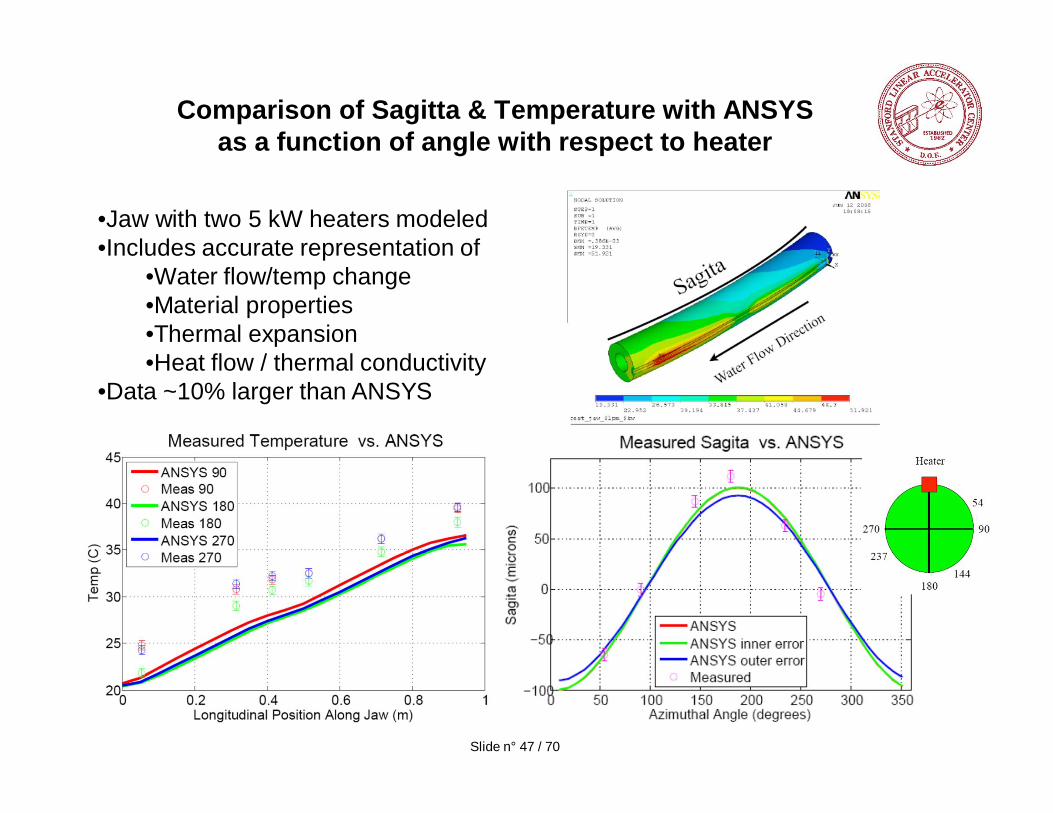
Comparison of Sagitta & Temperature with ANSYS as a function of angle with respect to heater
•Jaw with two 5 kW heaters modeled•Includes accurate representation of
•Water flow/temp change•Material properties•Thermal expansion•Heat flow / thermal conductivity
•Data ~10% larger than ANSYS
Slide n° 47 / 70
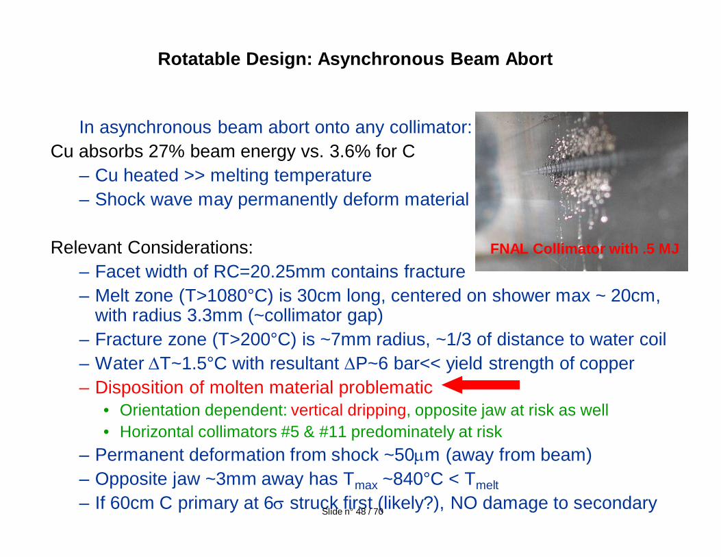
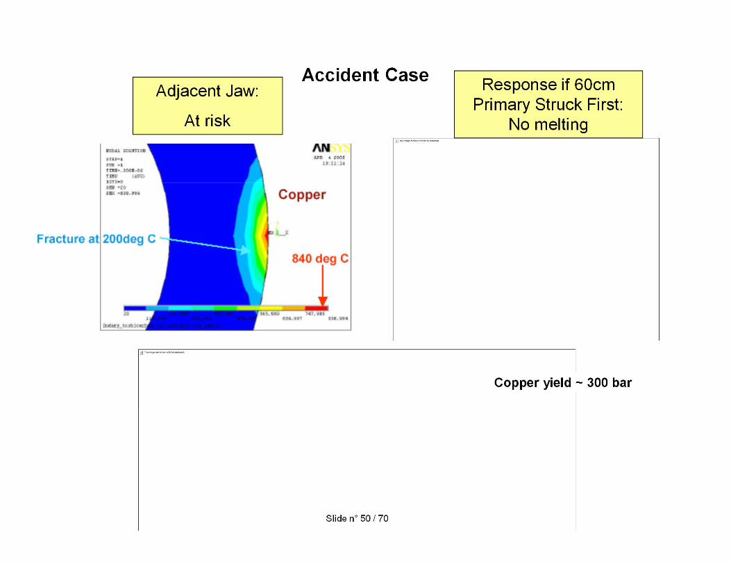
In asynchronous beam abort onto any collimator: Cu absorbs 27% beam energy vs. 3.6% for C
– Cu heated >> melting temperature – Shock wave may permanently deform material
Relevant Considerations:– Facet width of RC=20.25mm contains fracture– Melt zone (T>1080°C) is 30cm long, centered on shower max ~ 20cm,
with radius 3.3mm (~collimator gap)– Fracture zone (T>200°C) is ~7mm radius, ~1/3 of distance to water coil– Water T~1.5°C with resultant P~6 bar<< yield strength of copper– Disposition of molten material problematic
• Orientation dependent: vertical dripping, opposite jaw at risk as well• Horizontal collimators #5 & #11 predominately at risk
– Permanent deformation from shock ~50 m (away from beam)– Opposite jaw ~3mm away has Tmax ~840°C < Tmelt– If 60cm C primary at 6 struck first (likely?), NO damage to secondary
Rotatable Design: Asynchronous Beam Abort
FNAL Collimator with .5 MJ
Slide n° 48 / 70
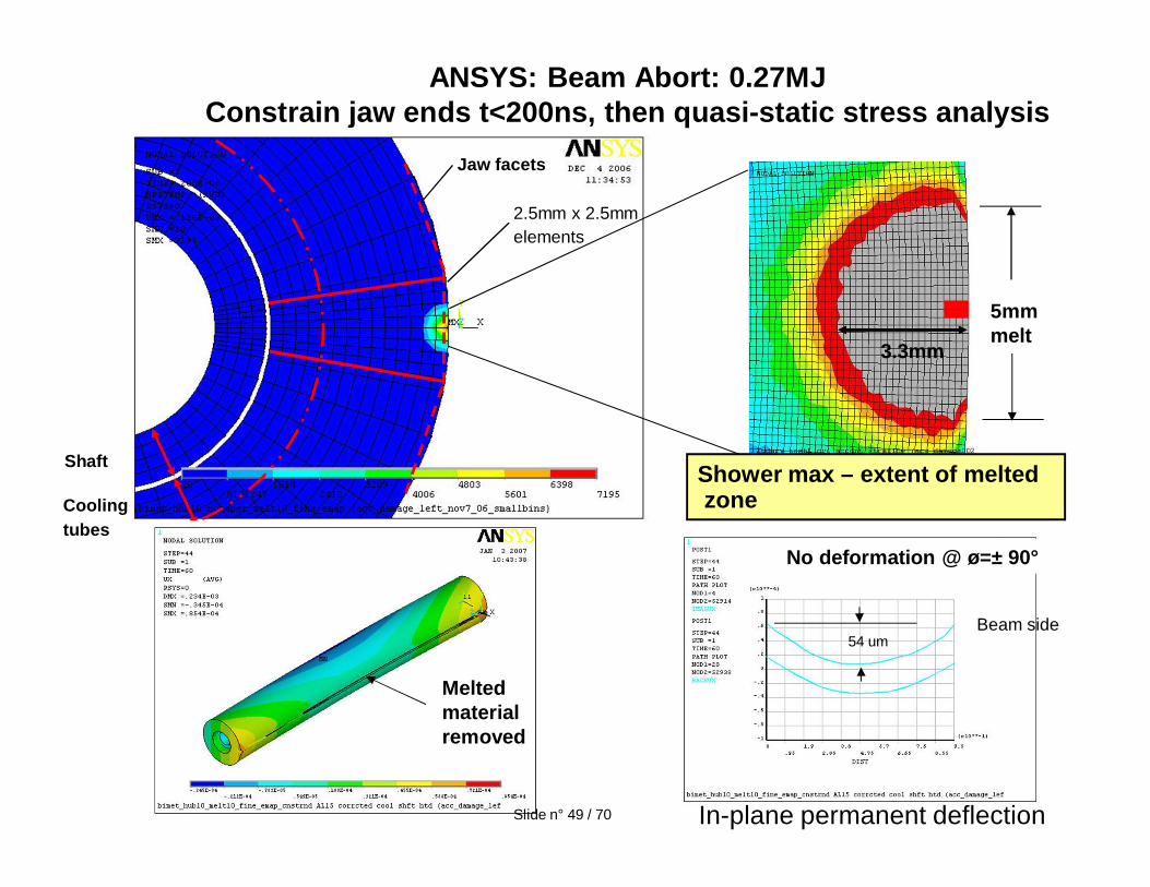
ANSYS: Beam Abort: 0.27MJConstrain jaw ends t<200ns, then quasi-static stress analysis
5mmmelt
2.5mm x 2.5mmelements
Shower max – extent of meltedzone
3.3mm
Coolingtubes
Shaft
Jaw facets
In-plane permanent deflection
54 umBeam side
Melted material removed
No deformation @ ø=± 90°
Slide n° 49 / 70
Accident CaseAdjacent Jaw:
At risk
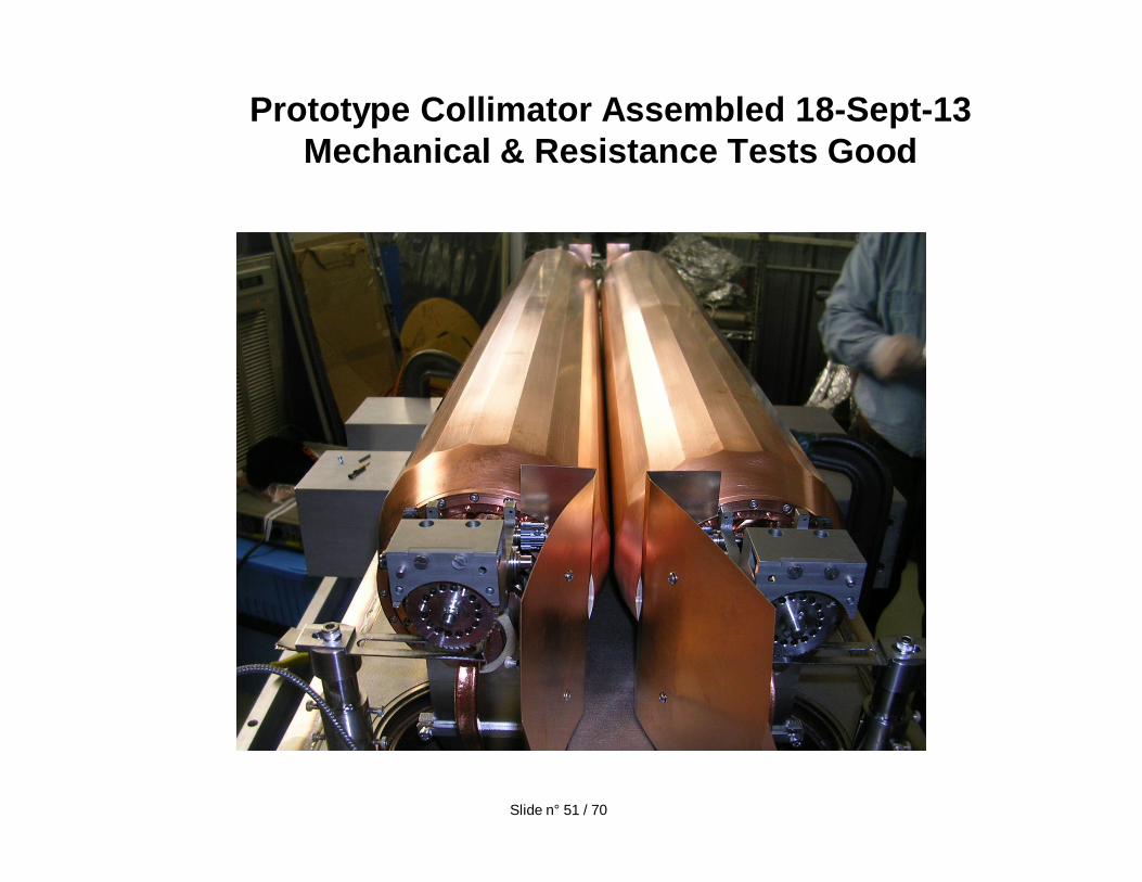
Prototype Collimator Assembled 18-Sept-13Mechanical & Resistance Tests Good
Slide n° 51 / 70
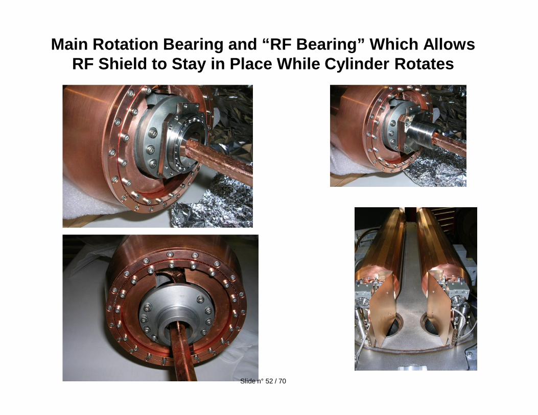
Main Rotation Bearing and “RF Bearing” Which Allows RF Shield to Stay in Place While Cylinder Rotates
Slide n° 52 / 70
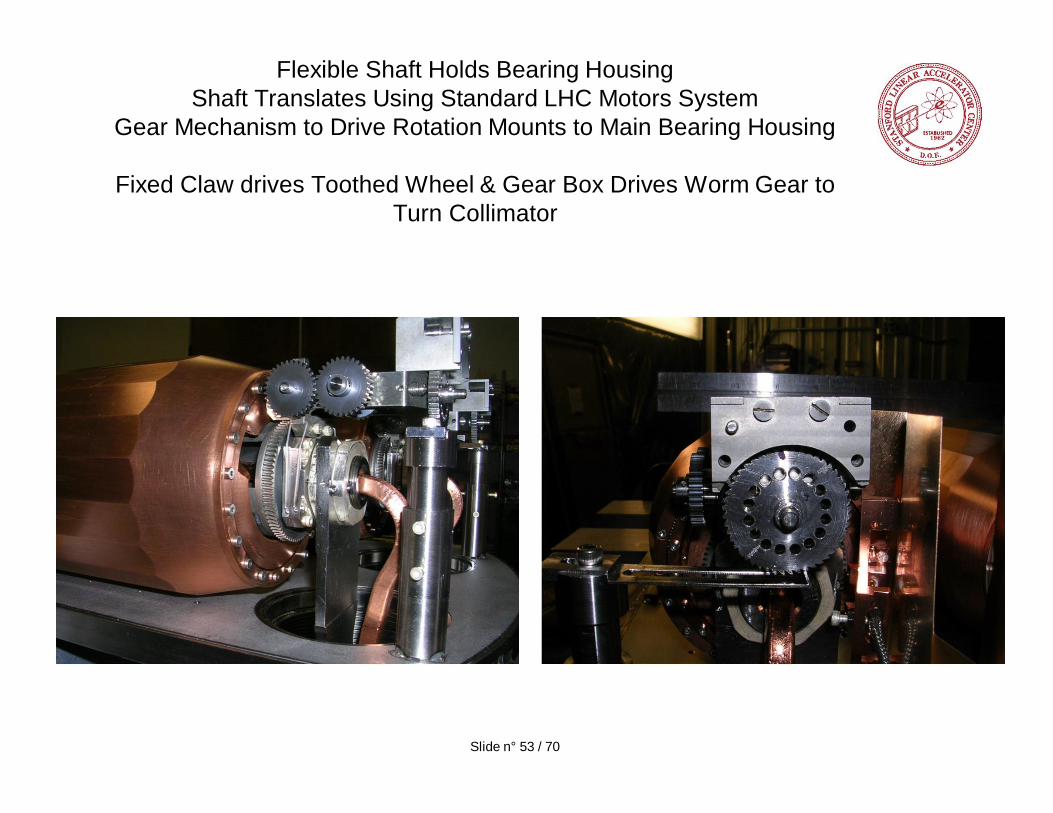
Flexible Shaft Holds Bearing HousingShaft Translates Using Standard LHC Motors System
Gear Mechanism to Drive Rotation Mounts to Main Bearing Housing
Fixed Claw drives Toothed Wheel & Gear Box Drives Worm Gear to Turn Collimator
Slide n° 53 / 70
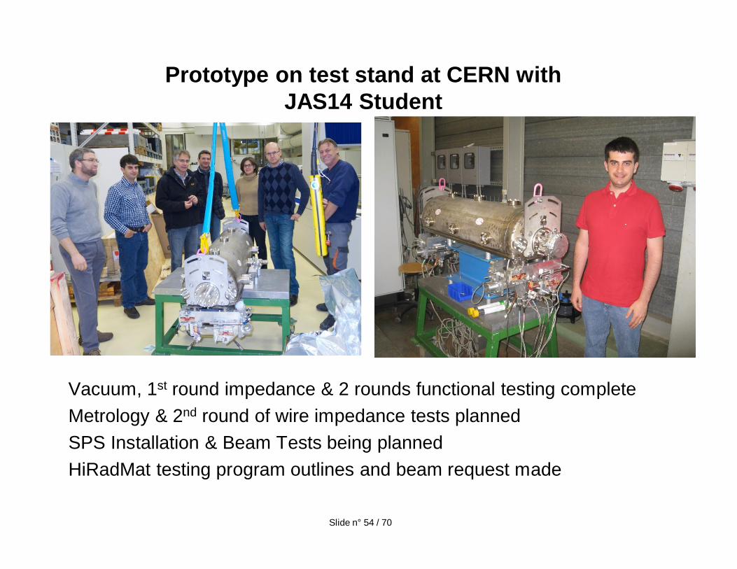
Vacuum, 1st round impedance & 2 rounds functional testing completeMetrology & 2nd round of wire impedance tests plannedSPS Installation & Beam Tests being plannedHiRadMat testing program outlines and beam request made
Prototype on test stand at CERN with JAS14 Student
Slide n° 54 / 70
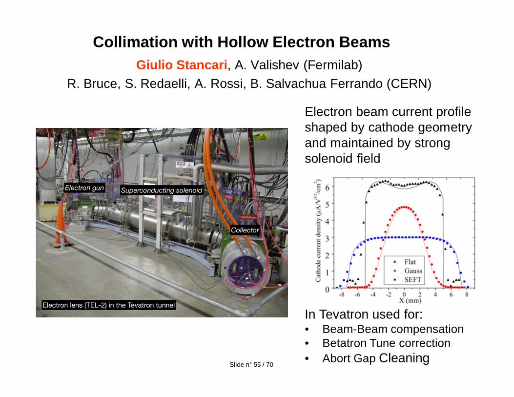
Giulio Stancari, A. Valishev (Fermilab)R. Bruce, S. Redaelli, A. Rossi, B. Salvachua Ferrando (CERN)
Collimation with Hollow Electron Beams
Electron beam current profile shaped by cathode geometry and maintained by strong solenoid eld
In Tevatron used for:• Beam-Beam compensation• Betatron Tune correction• Abort Gap Cleaning
Slide n° 55 / 70
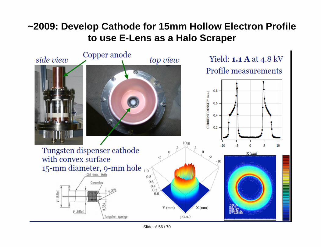
~2009: Develop Cathode for 15mm Hollow Electron Profile to use E-Lens as a Halo Scraper
Slide n° 56 / 70
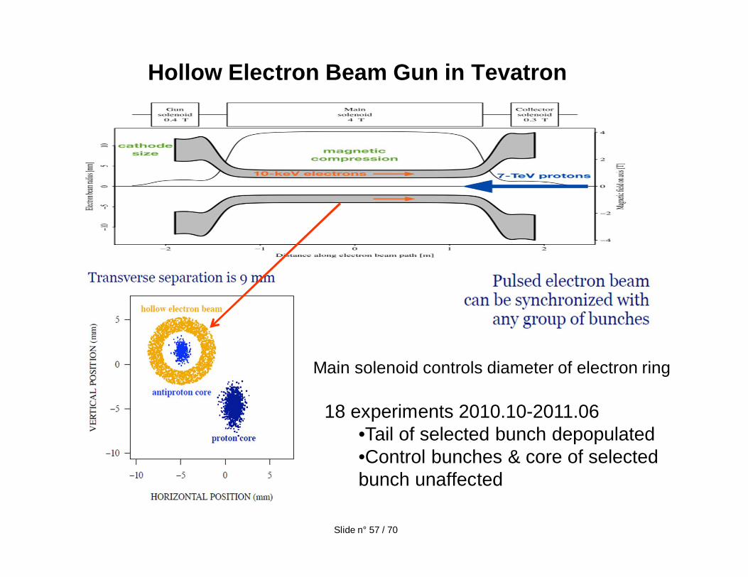
Hollow Electron Beam Gun in Tevatron
18 experiments 2010.10-2011.06•Tail of selected bunch depopulated•Control bunches & core of selected bunch unaffected
Slide n° 57 / 70
Main solenoid controls diameter of electron ring
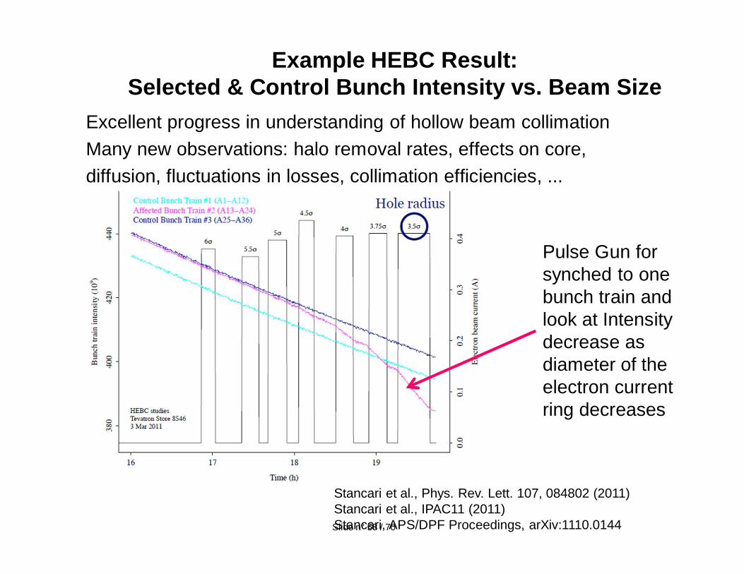
Excellent progress in understanding of hollow beam collimationMany new observations: halo removal rates, effects on core,diffusion, fluctuations in losses, collimation efficiencies, ...
Example HEBC Result: Selected & Control Bunch Intensity vs. Beam Size
Pulse Gun for synched to one bunch train and look at Intensity decrease as diameter of the electron current ring decreases
Stancari et al., Phys. Rev. Lett. 107, 084802 (2011)Stancari et al., IPAC11 (2011)Stancari, APS/DPF Proceedings, arXiv:1110.0144Slide n° 58 / 70
Slide n° 59 / 70
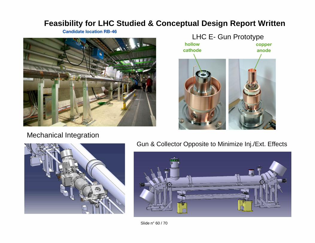
Feasibility for LHC Studied & Conceptual Design Report Written
Mechanical IntegrationGun & Collector Opposite to Minimize Inj./Ext. Effects
LHC E- Gun Prototype
Slide n° 60 / 70
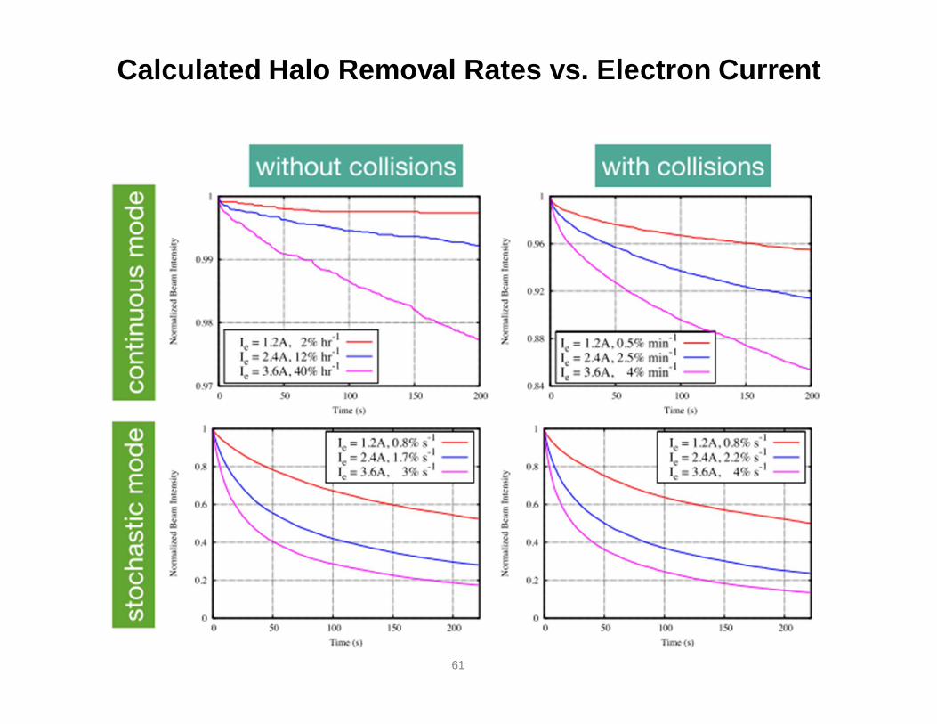
Calculated Halo Removal Rates vs. Electron Current
61
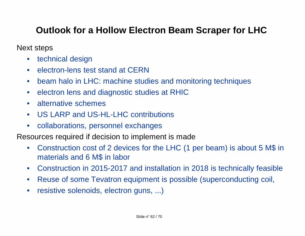
Next steps• technical design• electron-lens test stand at CERN• beam halo in LHC: machine studies and monitoring techniques• electron lens and diagnostic studies at RHIC• alternative schemes• US LARP and US-HL-LHC contributions• collaborations, personnel exchanges
Resources required if decision to implement is made• Construction cost of 2 devices for the LHC (1 per beam) is about 5 M$ in
materials and 6 M$ in labor• Construction in 2015-2017 and installation in 2018 is technically feasible• Reuse of some Tevatron equipment is possible (superconducting coil, • resistive solenoids, electron guns, ...)
Outlook for a Hollow Electron Beam Scraper for LHC
Slide n° 62 / 70
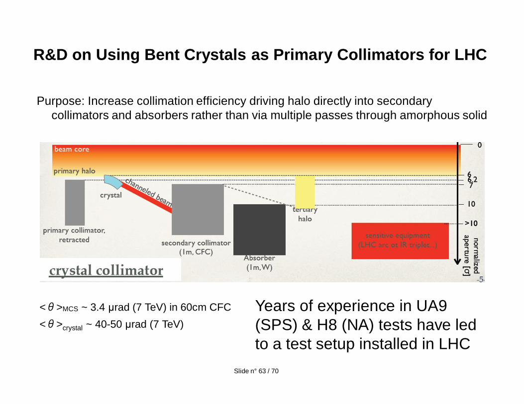
Purpose: Increase collimation efficiency driving halo directly into secondary collimators and absorbers rather than via multiple passes through amorphous solid
R&D on Using Bent Crystals as Primary Collimators for LHC
< >MCS ~ 3.4 rad (7 TeV) in 60cm CFC< >crystal ~ 40-50 rad (7 TeV)
Years of experience in UA9 (SPS) & H8 (NA) tests have led to a test setup installed in LHC
Slide n° 63 / 70
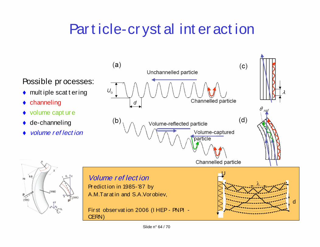
Particle-crystal interaction
Possible processes:multiple scatteringchannelingvolume capturede-channelingvolume reflection
d
UVolume reflectionPrediction in 1985-’87 byA.M.Taratin and S.A.Vorobiev,
First observation 2006 (IHEP - PNPI -CERN)
Slide n° 64 / 70
Rotation angle (µrad)
Ang
ular
pro
file
(µra
d)
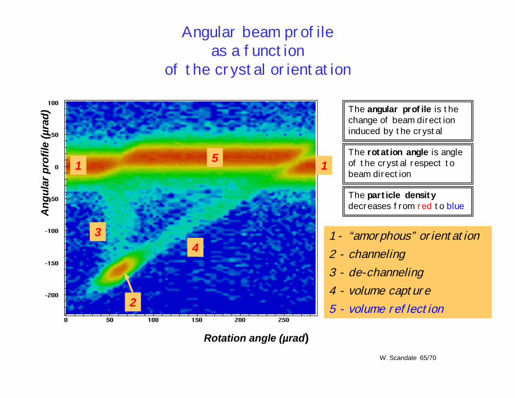
1 - “amorphous” orientation2 - channeling 3 - de-channeling4 - volume capture5 - volume reflection
Angular beam profileas a function
of the crystal orientation
1 1
34
2
5
The particle densitydecreases from red to blue
The angular profile is the change of beam direction induced by the crystal
The rotation angle is angle of the crystal respect to beam direction
W. Scandale 65/70
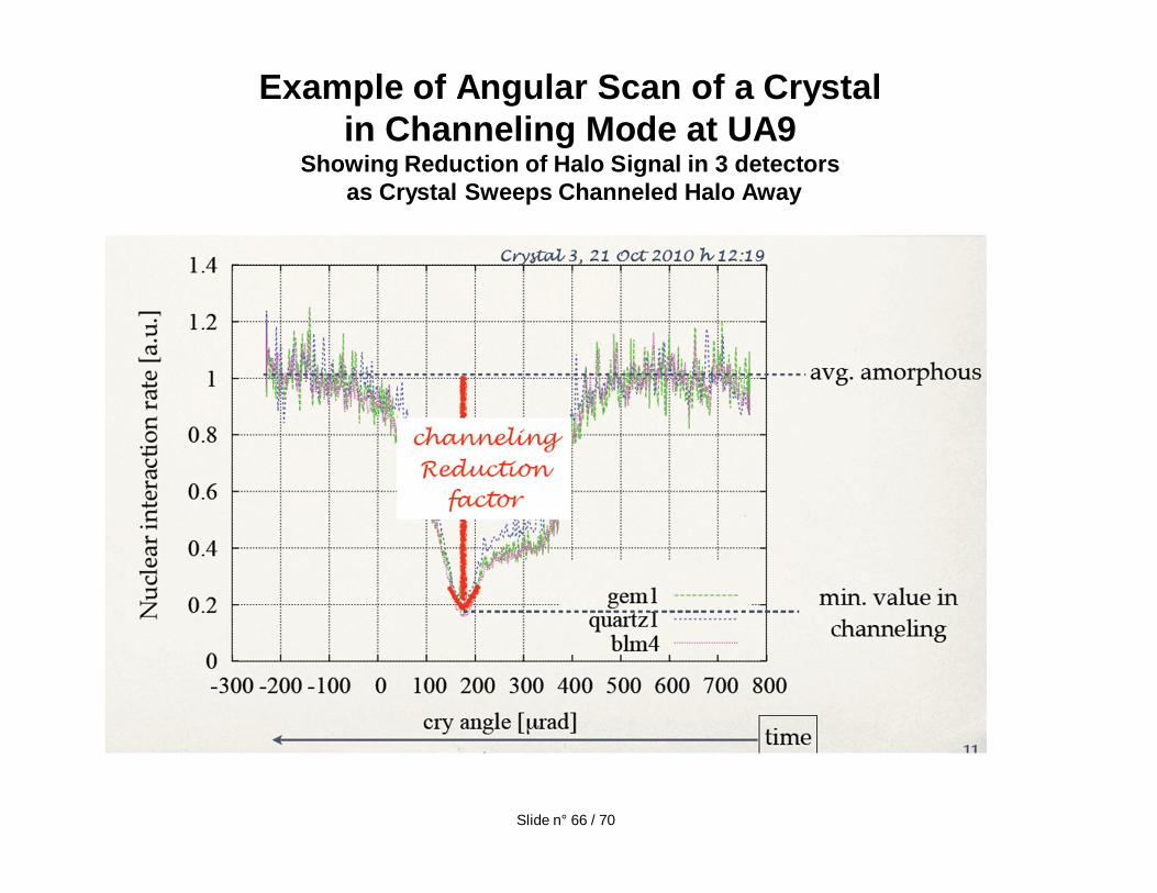
Example of Angular Scan of a Crystal in Channeling Mode at UA9
Showing Reduction of Halo Signal in 3 detectorsas Crystal Sweeps Channeled Halo Away
Slide n° 66 / 70
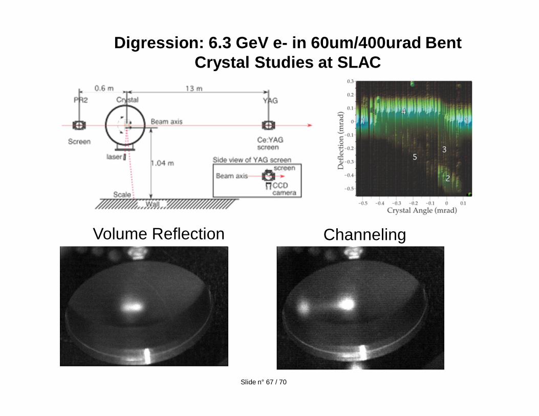
Digression: 6.3 GeV e- in 60um/400urad Bent Crystal Studies at SLAC
ChannelingVolume Reflection
Slide n° 67 / 70
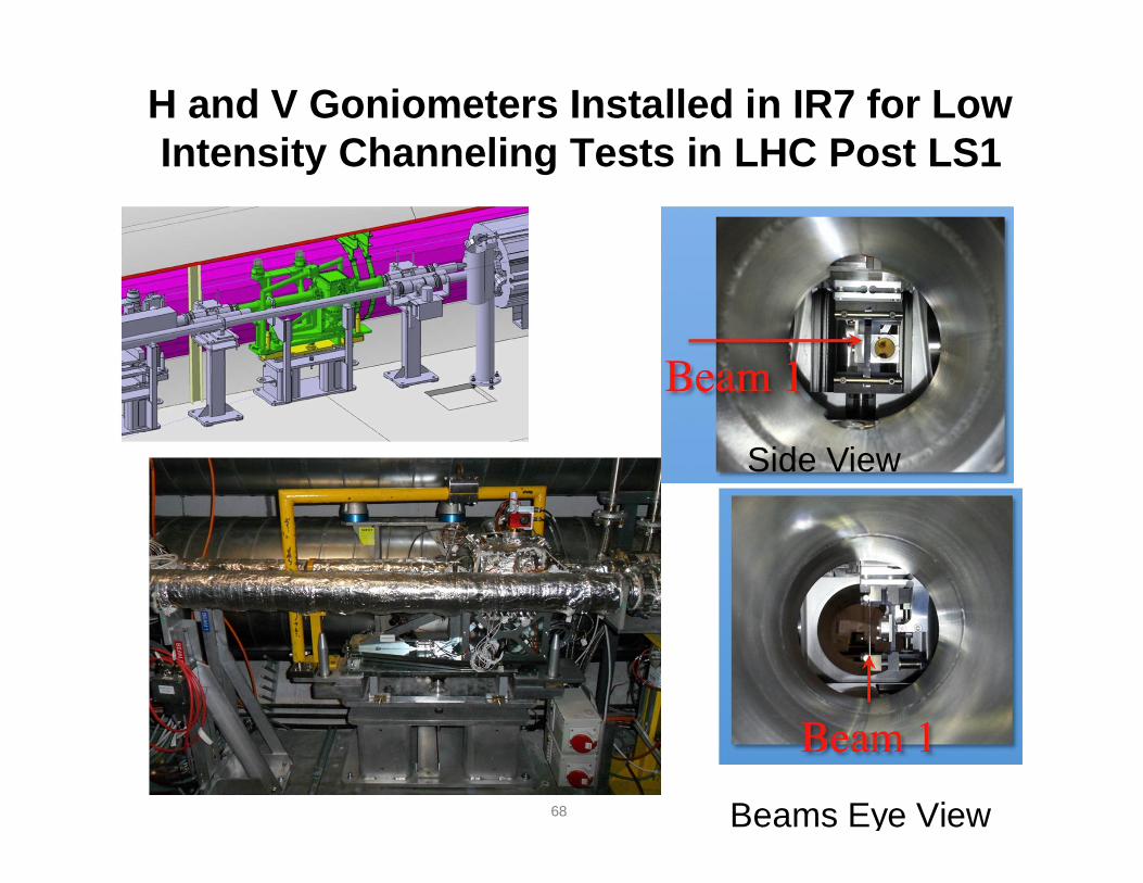
H and V Goniometers Installed in IR7 for Low Intensity Channeling Tests in LHC Post LS1
68 Beams Eye View
Side View
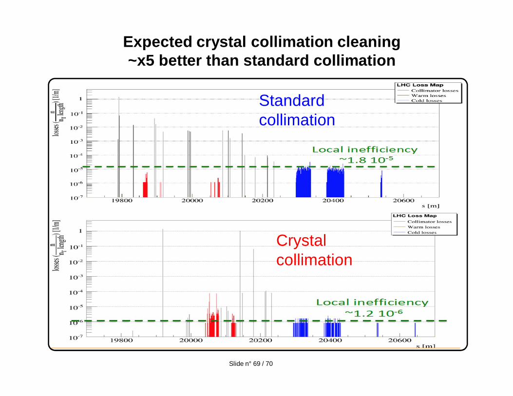
Expected crystal collimation cleaning ~x5 better than standard collimation
Standard collimation
Crystal collimation
Slide n° 69 / 70
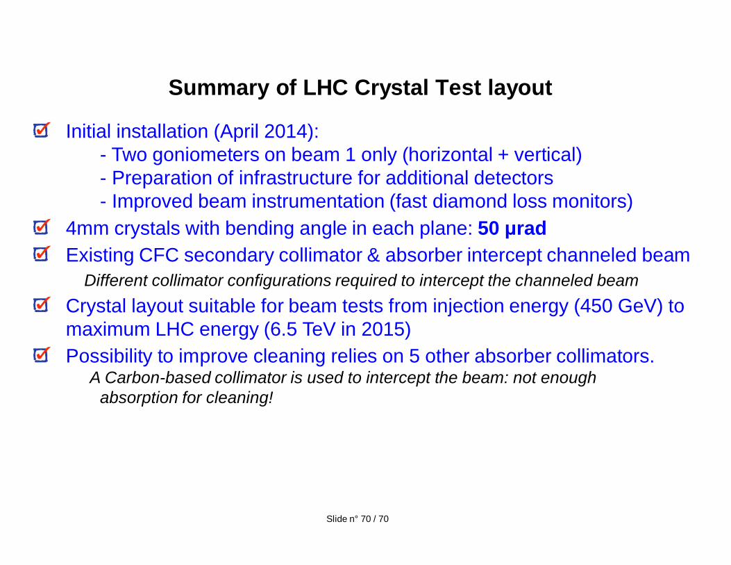
Summary of LHC Crystal Test layout
Initial installation (April 2014): - Two goniometers on beam 1 only (horizontal + vertical)- Preparation of infrastructure for additional detectors- Improved beam instrumentation (fast diamond loss monitors)
4mm crystals with bending angle in each plane: 50 radExisting CFC secondary collimator & absorber intercept channeled beam
Different collimator configurations required to intercept the channeled beamCrystal layout suitable for beam tests from injection energy (450 GeV) to maximum LHC energy (6.5 TeV in 2015) Possibility to improve cleaning relies on 5 other absorber collimators.
A Carbon-based collimator is used to intercept the beam: not enough absorption for cleaning!
Slide n° 70 / 70

The End
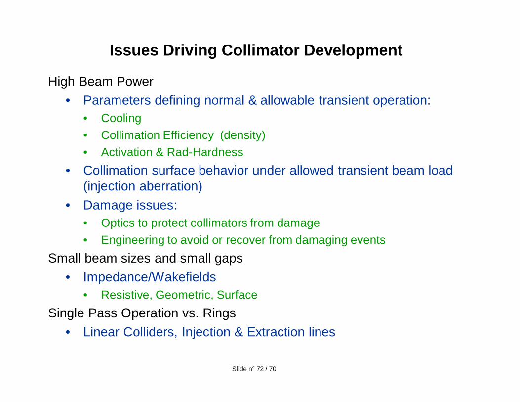
High Beam Power• Parameters defining normal & allowable transient operation:
• Cooling• Collimation Efficiency (density) • Activation & Rad-Hardness
• Collimation surface behavior under allowed transient beam load (injection aberration)
• Damage issues:• Optics to protect collimators from damage• Engineering to avoid or recover from damaging events
Small beam sizes and small gaps• Impedance/Wakefields
• Resistive, Geometric, SurfaceSingle Pass Operation vs. Rings
• Linear Colliders, Injection & Extraction lines
Issues Driving Collimator Development
Slide n° 72 / 70
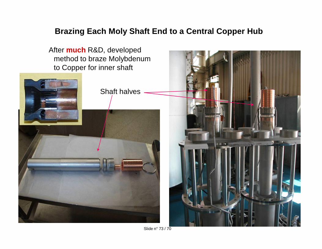
Brazing Each Moly Shaft End to a Central Copper Hub
After much R&D, developed method to braze Molybdenum to Copper for inner shaft
Shaft halves
Slide n° 73 / 70
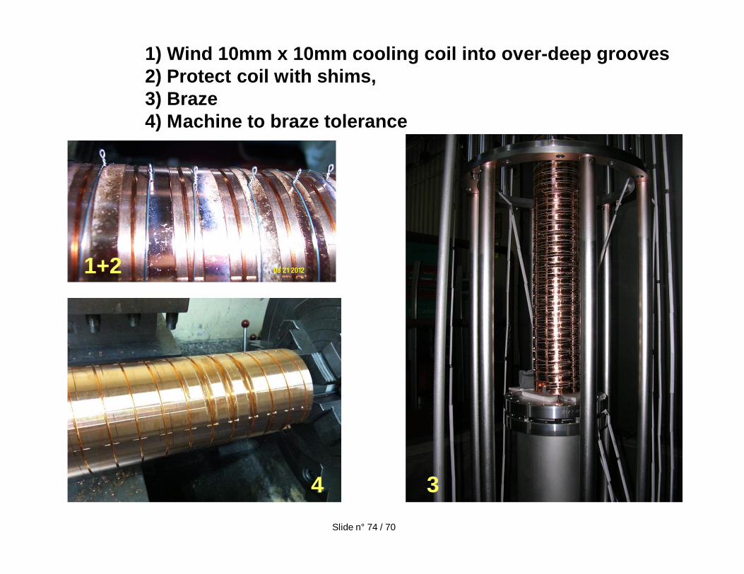
1) Wind 10mm x 10mm cooling coil into over-deep grooves2) Protect coil with shims, 3) Braze 4) Machine to braze tolerance
1+2
34Slide n° 74 / 70
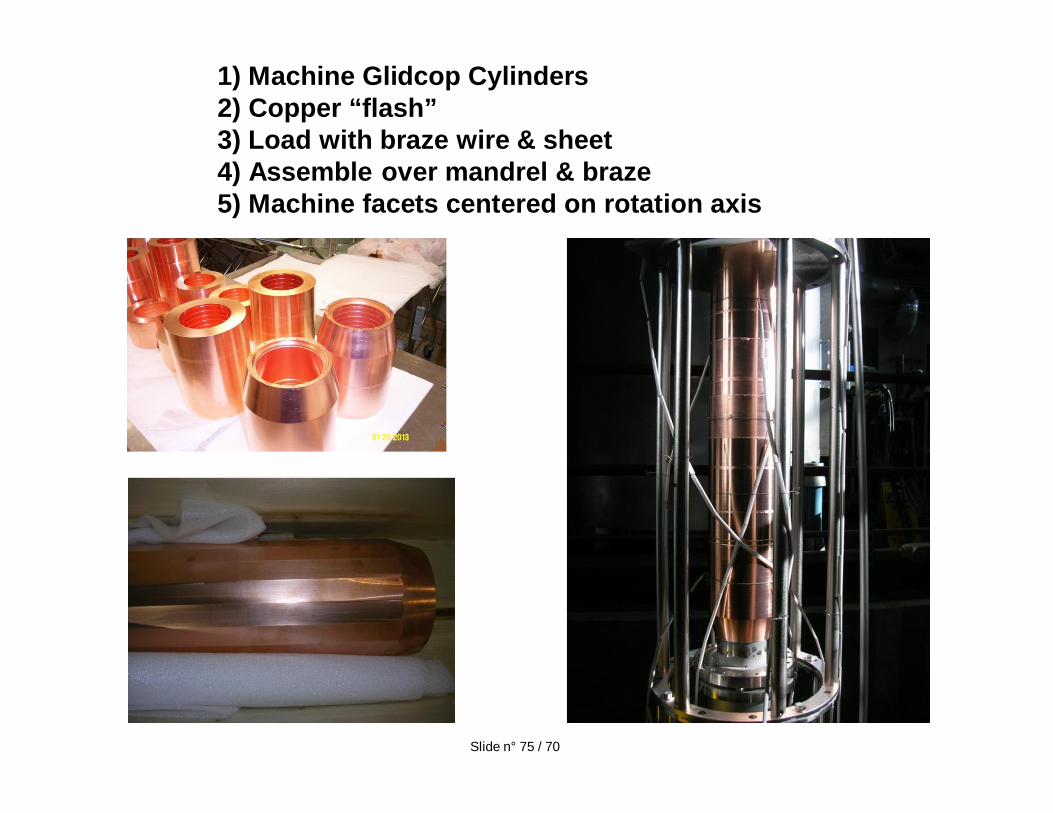
1) Machine Glidcop Cylinders2) Copper “flash”3) Load with braze wire & sheet4) Assemble over mandrel & braze5) Machine facets centered on rotation axis
Slide n° 75 / 70
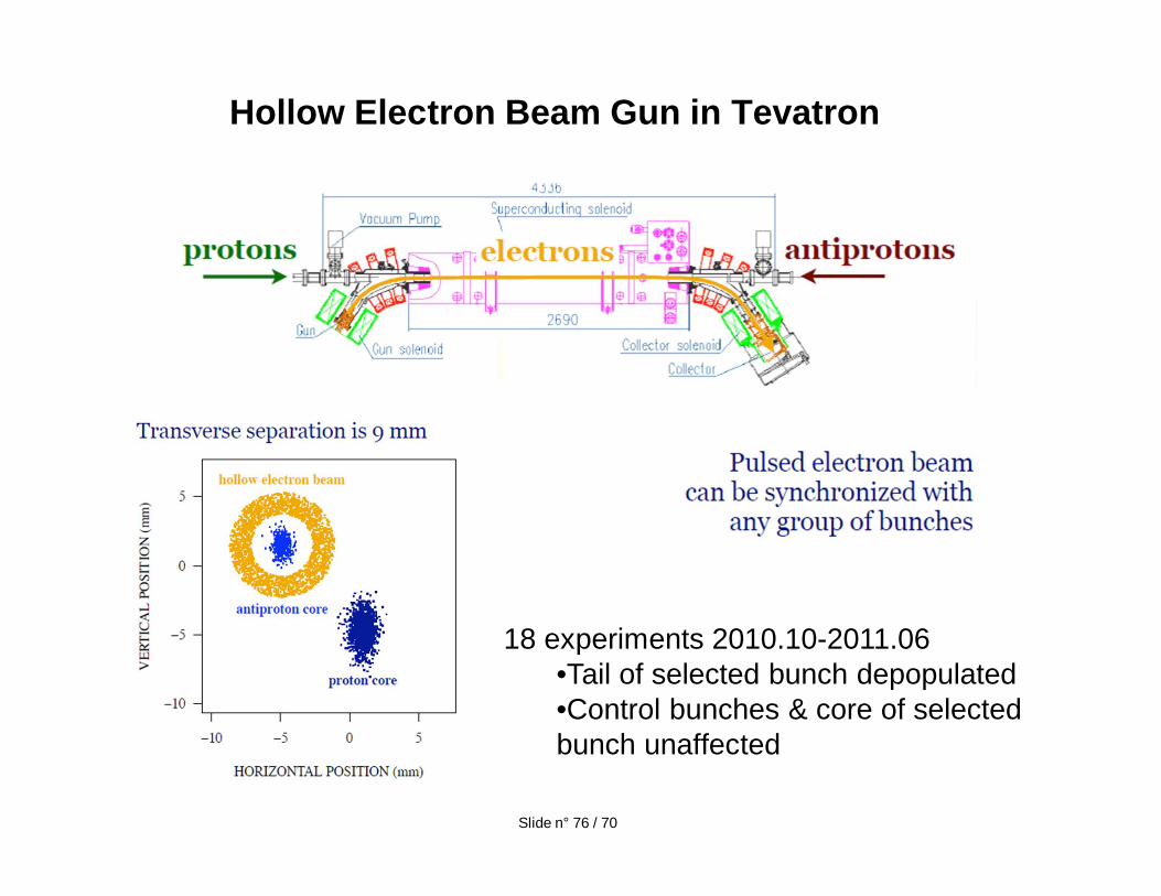
Hollow Electron Beam Gun in Tevatron
18 experiments 2010.10-2011.06•Tail of selected bunch depopulated•Control bunches & core of selected bunch unaffected
Slide n° 76 / 70