advanced coil selection with respect to performance at ...coil selection •step 3a: select coil...
TRANSCRIPT
Advanced Coil Selection
with Respect to Performance at Minimum Flow
ConditionsPresented by: Gene Nelson, PE
November 12, 2018

Good Judgment
comes from experience.

Good Judgment
comes from experience.
Experience
comes from poor judgment.
LEARNING OBJECTIVES
• Why coil selections at low flow conditions are important
• Basic science regarding coil performance
• How to select coils• How and When To Use Pumped Coils
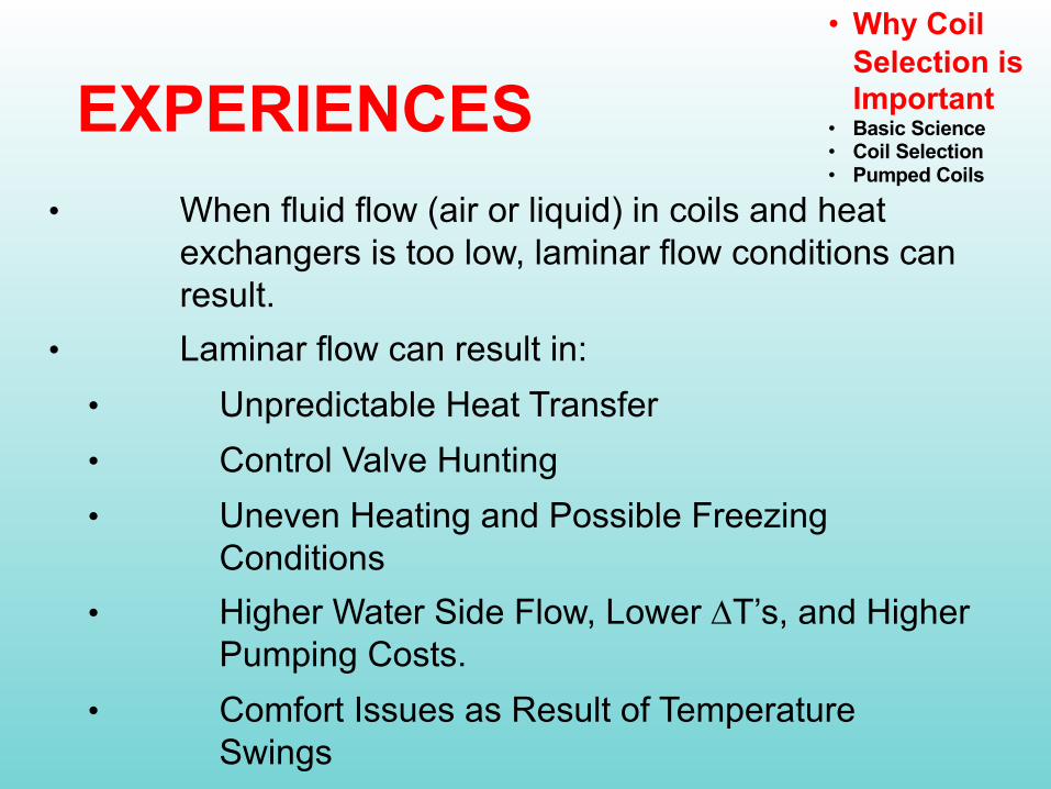
• When fluid flow (air or liquid) in coils and heat exchangers is too low, laminar flow conditions can result.
• Laminar flow can result in:• Unpredictable Heat Transfer• Control Valve Hunting• Uneven Heating and Possible Freezing
Conditions• Higher Water Side Flow, Lower DT’s, and Higher
Pumping Costs.• Comfort Issues as Result of Temperature
Swings
• Why Coil Selection is Important
• Basic Science• Coil Selection• Pumped Coils
EXPERIENCES

• Energy Conservation Measures have forced us to
• Oversize coils to lower airside and waterside pressure drops
• Use variable flow as much as possible
• Coils and heat exchangers operate at part load conditions over 99% of the time, up to 70% below 50%.
• Low loads usually occur in spring and fall and during unoccupied times
EXPERIENCES

HEATING PART LOAD HOURSFOR A SAMPLE 600,000 SF LABORATORY
Percent of Full Load
Percent of AnnualHours
0.0%
5.0%
10.0%
15.0%
20.0%
25.0%
30.0%
35.0%
40.0%
<10% 10-19% 20-29% 30-39% 40-49% 50-59% 60-69% 70-79% 80-89%
HEATING LOAD
60% of hours has a load of < 30%82% of hours has a load of < 50%
Average Load = 30%
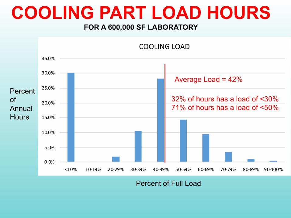
COOLING PART LOAD HOURSFOR A 600,000 SF LABORATORY
Percent of Full Load
Percent of AnnualHours
0.0%
5.0%
10.0%
15.0%
20.0%
25.0%
30.0%
35.0%
<10% 10-19% 20-29% 30-39% 40-49% 50-59% 60-69% 70-79% 80-89% 90-100%
COOLING LOAD
Average Load = 42%
32% of hours has a load of <30%71% of hours has a load of <50%
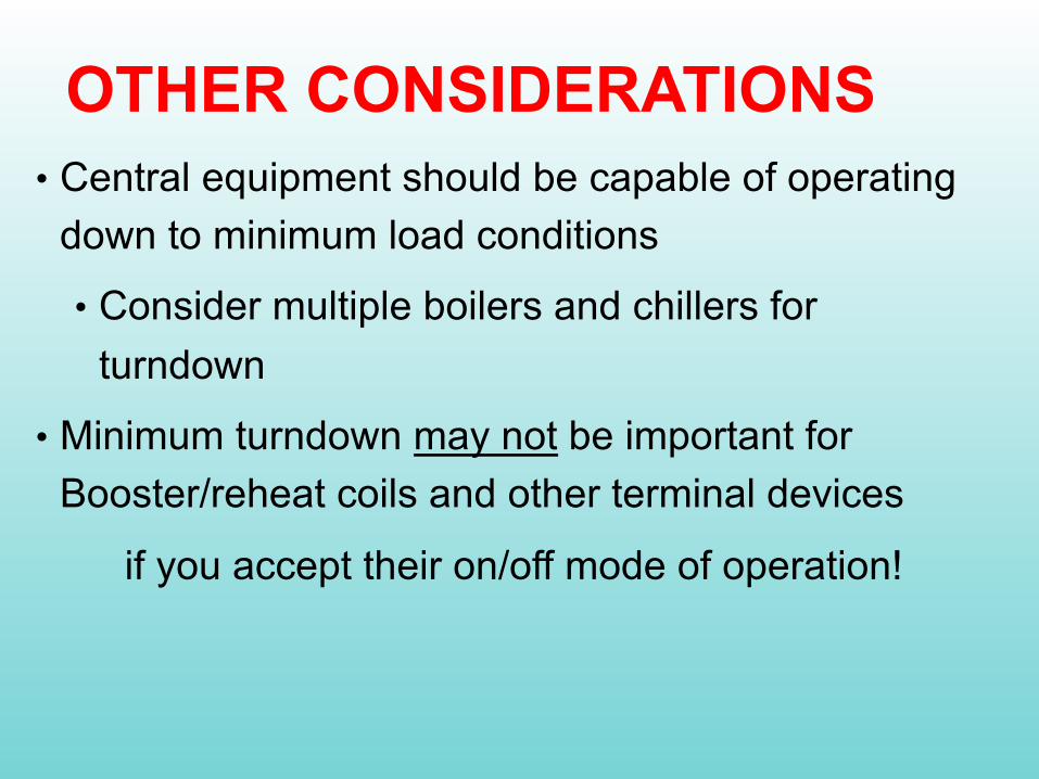
• Central equipment should be capable of operating down to minimum load conditions
• Consider multiple boilers and chillers for turndown
• Minimum turndown may not be important for Booster/reheat coils and other terminal devices
if you accept their on/off mode of operation!
OTHER CONSIDERATIONS

q = hc As (ts –th) Equation 2 from 2017 ASHRAE Handbook of Fundamentals, Chapter 4
where:
q = energy transfer (BTU/Hour)
hc = convective heat transfer coefficient
(BTU/Hr-SF-F)
As = heat transfer area (SF)
ts = surface temperature (oF)
th = fluid temperature (oF)
• Coil Selection is Important
• Basic Science• Coil Selection• Pumped Coils

Nu = hLc/k = f(ReLcPr) Where: Nu = Nusselt number
h = convective heat transfer coefficient Lc = characteristic lengthReLc = Reynolds number = ρVLc/u = VLc/vV = fluid velocityPr = Prandtl number = cpu/kcp = fluid specific heatu = fluid dynamic viscosityρ = fluid densityv = kinematic viscosity = u/ ρk = fluid conductivity

FLUID FLOW IN TUBES
8,000
Figure from 2017 ASHRAE Handbook of Fundamentals, Chapter 4
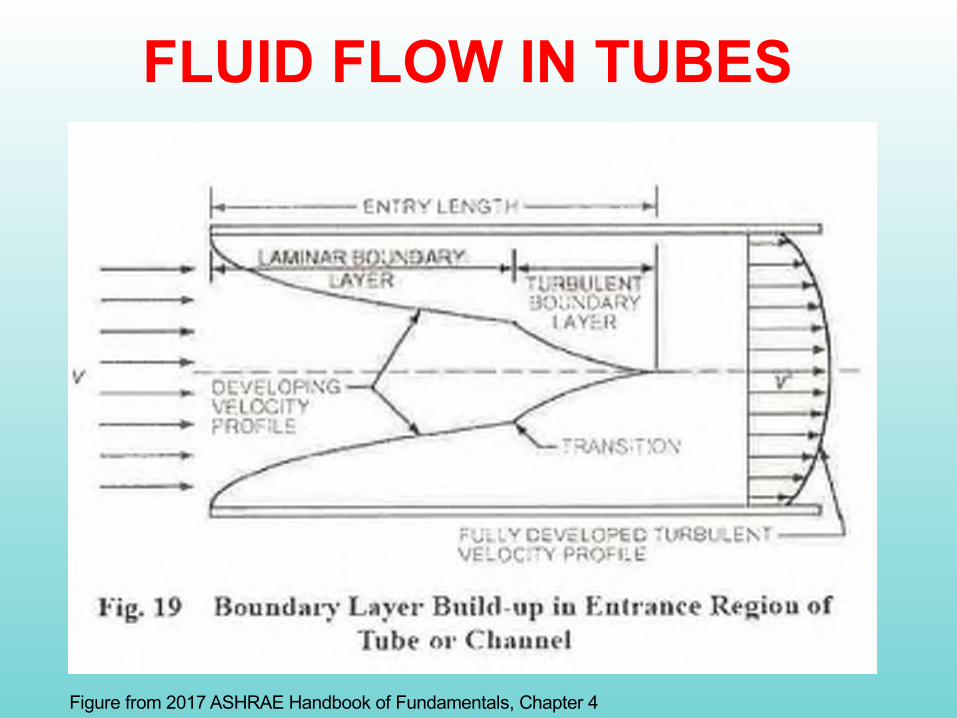
FLUID FLOW IN TUBES
Figure from 2017 ASHRAE Handbook of Fundamentals, Chapter 4
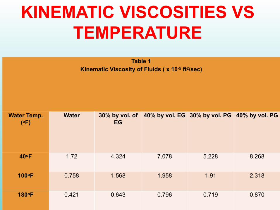
Table 1Kinematic Viscosity of Fluids ( x 10-5 ft2/sec)
Water Temp. (oF)
Water 30% by vol. of EG
40% by vol. EG 30% by vol. PG 40% by vol. PG
40oF 1.72 4.324 7.078 5.228 8.268
100oF 0.758 1.568 1.958 1.91 2.318
180oF 0.421 0.643 0.796 0.719 0.870
KINEMATIC VISCOSITIES VS TEMPERATURE
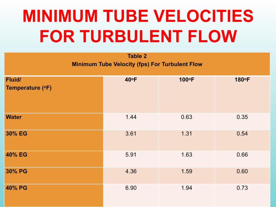
Table 2Minimum Tube Velocity (fps) For Turbulent Flow
Fluid/Temperature (oF)
40oF 100oF 180oF
Water 1.44 0.63 0.35
30% EG 3.61 1.31 0.54
40% EG 5.91 1.63 0.66
30% PG 4.36 1.59 0.60
40% PG 6.90 1.94 0.73
MINIMUM TUBE VELOCITIES FOR TURBULENT FLOW
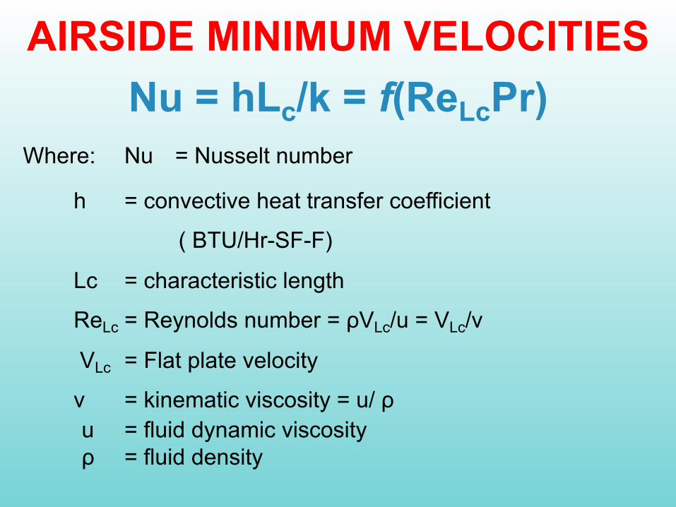
AIRSIDE MINIMUM VELOCITIESNu = hLc/k = f(ReLcPr)
Where: Nu = Nusselt number
h = convective heat transfer coefficient
( BTU/Hr-SF-F)
Lc = characteristic length
ReLc = Reynolds number = ρVLc/u = VLc/v
VLc = Flat plate velocity
v = kinematic viscosity = u/ ρu = fluid dynamic viscosityρ = fluid density
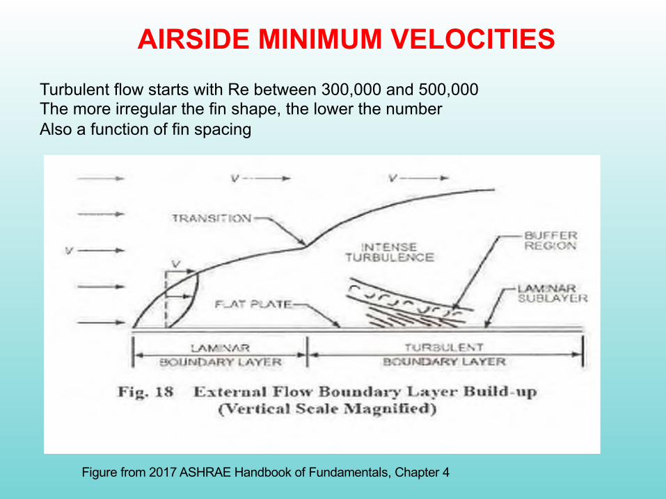
AIRSIDE MINIMUM VELOCITIESTurbulent flow starts with Re between 300,000 and 500,000The more irregular the fin shape, the lower the numberAlso a function of fin spacing
Figure from 2017 ASHRAE Handbook of Fundamentals, Chapter 4

Table 3Kinematic Viscosity of Air
(v) ft2/secat various temperatures
cold air (0oF at 80% RH) v = 1.264 x 10⁻⁴
medium air (60oF @ 80%RH)v = 1.607 x 10⁻⁴
warm air (100oF@ 40% RH)v = 1.826 x 10⁻⁴

Effective Coil Area Function of Face Velocity for
1 Row Booster Coil (4.5” depth)
0.0%
10.0%
20.0%
30.0%
40.0%
50.0%
60.0%
70.0%
80.0%
90.0%
0 10 20 30 40 50 60 70 80 90 100
% o
f Fin
Use
d
Average Temperature Across Coil
600 fpm
500 fpm
400 fpm
300 fpm
200 fpm
150 fpm
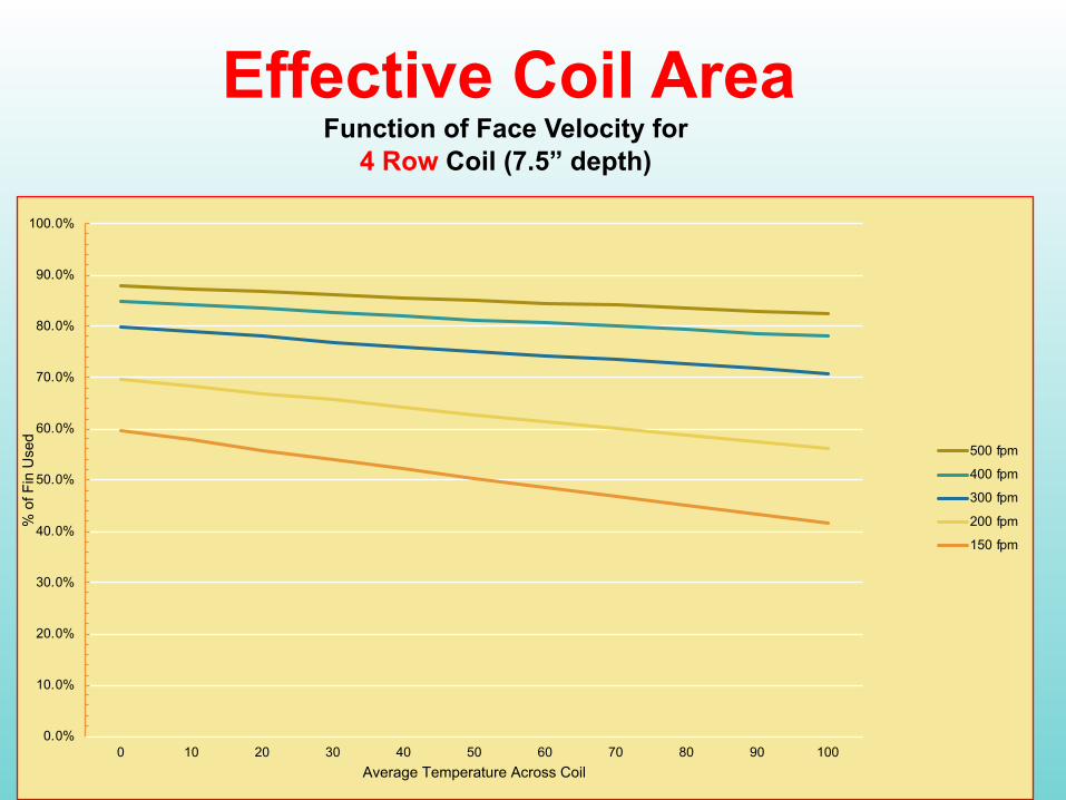
Effective Coil Area Function of Face Velocity for
4 Row Coil (7.5” depth)
0.0%
10.0%
20.0%
30.0%
40.0%
50.0%
60.0%
70.0%
80.0%
90.0%
100.0%
0 10 20 30 40 50 60 70 80 90 100
% o
f Fin
Use
d
Average Temperature Across Coil
500 fpm
400 fpm
300 fpm
200 fpm
150 fpm
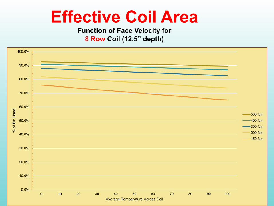
Effective Coil Area Function of Face Velocity for
8 Row Coil (12.5” depth)
0.0%
10.0%
20.0%
30.0%
40.0%
50.0%
60.0%
70.0%
80.0%
90.0%
100.0%
0 10 20 30 40 50 60 70 80 90 100
% o
f Fin
Use
d
Average Temperature Across Coil
500 fpm
400 fpm
300 fpm
200 fpm
150 fpm

CONCLUSIONS• Coil Selection is
Important • Basic Science• Coil Selection• Pumped Coils
COIL DEPTH 1 ROW 2 OR 3 ROWS 4 ROWS 6 ROWS 8 ROWS
COOLING N/R 300 300 250 200PREHEAT N/R 400 300 250 200REHEAT 300 200 200 200 200
• Coil depth is a factor• 1 row coils should only be used for small
booster coils and should not be used for cooling or preheat coils, especially for VAV systems
RECOMMENDED MINUMUM COIL FACE VELOCITIES (FPM)

What have we learnedso far?
• Minimum tube velocities are important• Function of fluid type and temperature• Flow will become laminar at some point as flows
decrease.• Based on load profiles, attempt to pick coils with
turbulent flow for most of the hours at part load conditions. (Down to as far as possible)
• With 6 fps, turndown is only 4:1 for cooling, up to 10:1 for heating
• Minimum face velocities are important• Function of air temperature and coil depth
• Coil Selection is Important
• Basic Science• Coil Selection• Pumped Coils

RECOMMENDED MINIMUM TUBE VELOCITIES
COOLING LOW TEMP HEATING STD TEMP HEATING40-45OF 90-140OF 160-200OF
WATER 1.5 - 2 1.0 - 1.5 0.4 - 0.6
30% EG/PG 4 - 5 1.5 - 2 0.6 - 1
40% EG/PG AVOID 2 - 3 0.8 - 1.5
RECOMMENDED MINIMUM TUBE VELOCITIES (FPS)
2016 ASHRAE Systems Handbook – Ch. 23 and 27 discuss coil selection.
Max. tube velocity = 6 fps for copper
ASME Std AG-1: 2 fps min.
AHRI Std 410: 1 fps min., Re min = 3700
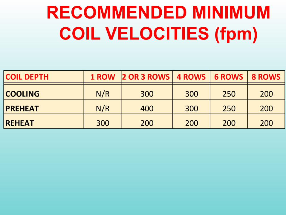
RECOMMENDED MINIMUM COIL VELOCITIES (fpm)
COIL DEPTH 1 ROW 2 OR 3 ROWS 4 ROWS 6 ROWS 8 ROWS
COOLING N/R 300 300 250 200PREHEAT N/R 400 300 250 200REHEAT 300 200 200 200 200
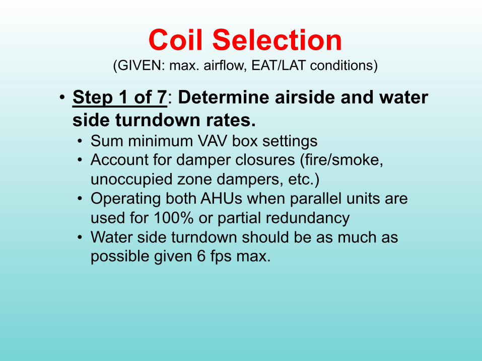
Coil Selection (GIVEN: max. airflow, EAT/LAT conditions)
• Step 1 of 7: Determine airside and water side turndown rates.• Sum minimum VAV box settings• Account for damper closures (fire/smoke,
unoccupied zone dampers, etc.)• Operating both AHUs when parallel units are
used for 100% or partial redundancy• Water side turndown should be as much as
possible given 6 fps max.

Coil Selection • Step 2: Determine number of coils and coil
sizes using maximum and minimum face velocities• Maximum face velocity for cooling coils should be
less than published coil carryover values (<550 fpm)
• No maximum face velocity for heating coils.• Practical limit is 900 fpm for AHU coils and 1500
for reheat coils• Determine minimum face velocity based on
system turndown.• Determine if multiple coils/AHUS are required or if
shutoff or face and bypass dampers are required to keep face velocity above minimum values.
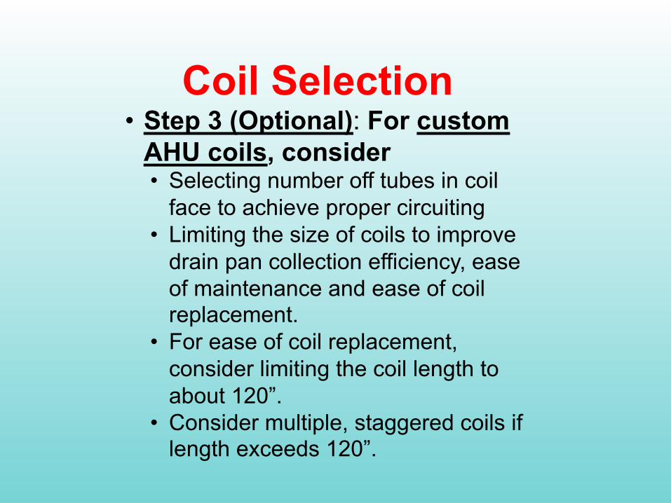
Coil Selection• Step 3 (Optional): For custom
AHU coils, consider • Selecting number off tubes in coil
face to achieve proper circuiting• Limiting the size of coils to improve
drain pan collection efficiency, ease of maintenance and ease of coil replacement.
• For ease of coil replacement, consider limiting the coil length to about 120”.
• Consider multiple, staggered coils if length exceeds 120”.

Coil Selection
• Step 3a: Select coil height based on number of tubes, tube size, and circuiting to achieve desired tube velocity• Number of tubes in coil face is a function of coil height• Tube sizes (3/8”, 1/2”, 5/8”)• Circuiting Options
• Full or 1 – All tubes in face have equal full.• Fraction circuiting (0.25, 0.33, 0.5, 0.75) – Multiple
tubes are circuited together to increase tube velocity• 1.5, 2 (double), and 3 (triple) circuiting – Flow is
divided to coil to reduce tube velocity

Coil Selection
• Number of coil tubes = coil height (in.) / 1.5” per tube
12” 8 tubes on 1.5” centers
• Total no. of tubes = tubes/coil ht. x no. of rows
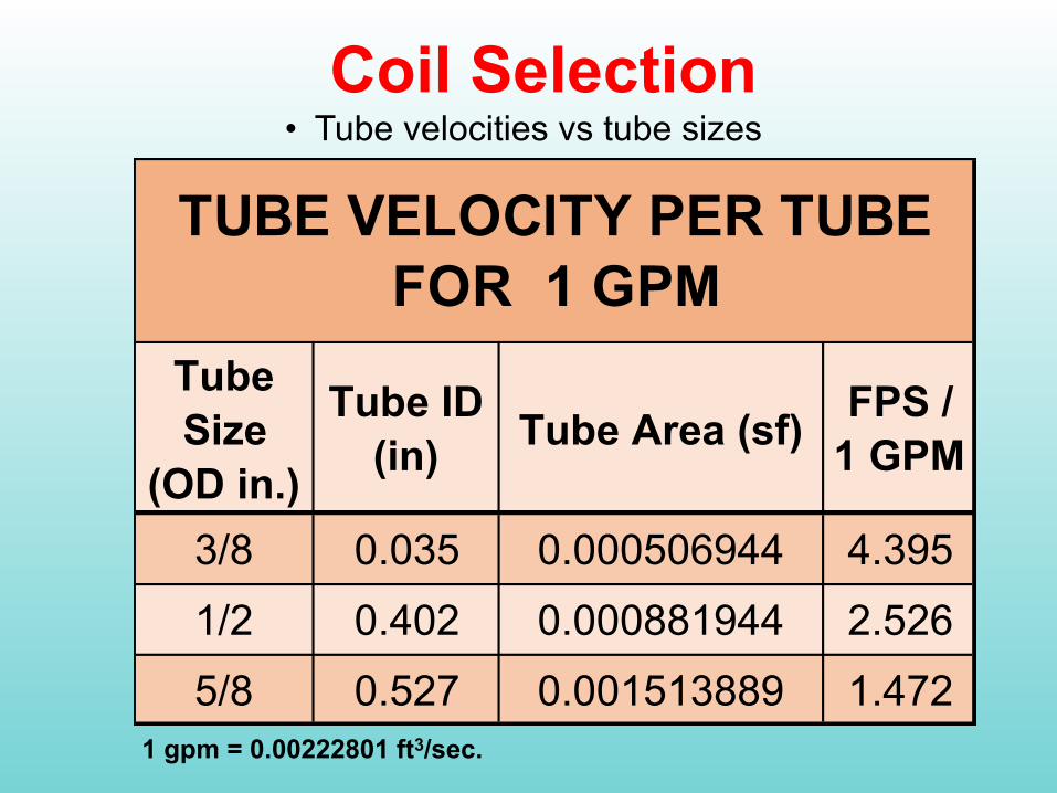
Coil Selection• Tube velocities vs tube sizes
Tube Size
(OD in.)
Tube ID (in) Tube Area (sf) FPS /
1 GPM
3/8 0.035 0.000506944 4.3951/2 0.402 0.000881944 2.5265/8 0.527 0.001513889 1.472
TUBE VELOCITY PER TUBE FOR 1 GPM
1 gpm = 0.00222801 ft3/sec.
Coil Selection
• Step 3b: Based on coil height and desired face area, determine
• Coil length (in) =Coil area sf x 144 / coil height (in)
Coil Selection
• Step 4: Based on coil height and initial guess at circuiting, determine
• Select tube size (diameter)• No. of circuits =
No. of tubes in coil height x circuiting number (percentage)
• Flow per circuit =Total coil flow / no. of circuits
• Estimated tube velocity =gpm/circuit x fps/gpm
• Repeat above steps to get desired tube velocity ( 6 fps max.)
Coil Selection
• Step 5: Start using coil selection software. Select tube and fin materials, and if any coatings are to be used.• Notes
• Booster coil software will preselect materials for you and limit coil sizes.
• Certain material options may be fixed by coil manufacturer
Coil Selection
• Step 5a: Enter air flow, EAT, and EWT conditions• Consider using adjusted EWTs when using pumped
coils
• Step 5b: Enter either LAT conditions, total MBH, or water flow, but not more than one• Best option is to enter water flow based on desired
temperature change• Consider using higher water flows when using
pumped coils to maintain minimum tube velocities

Coil Selection
• Step 5c: Enter first guess of coil selection• Coil type• Coil size• No. of rows (1 through 12)• Circuiting (quarter, third, half, three-quarter, full,
1.5, double, triple)• Tube diameter (3/8”, 1/2”, 5/8”)• Tube wall thickness (0.016” to 0.049”)

Coil Selection
• Step 5c: Enter first guess of coil selection• Fin Thickness (0.006” to 0.01”)• Fin material (aluminum, copper, SS)• Fin shape (flat, wave, enhanced wave)• Fin coatings for corrosion resistance (baked phenolic,
sprayed epoxy)• Casing material (Galvanized or SS)• Header connection sizes• LH or RH end connections
Coil Selection
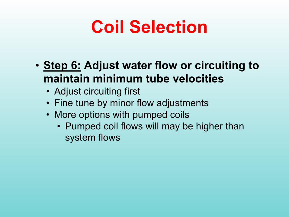
• Step 6: Adjust water flow or circuiting to maintain minimum tube velocities• Adjust circuiting first• Fine tune by minor flow adjustments• More options with pumped coils
• Pumped coil flows will may be higher than system flows
Coil Selection
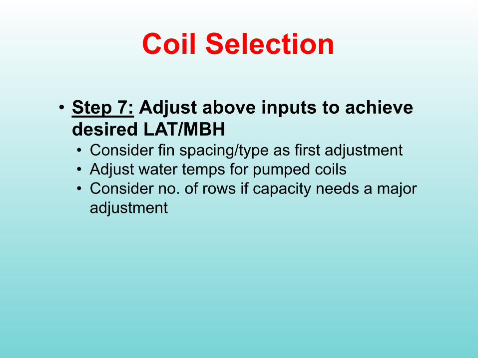
• Step 7: Adjust above inputs to achieve desired LAT/MBH• Consider fin spacing/type as first adjustment• Adjust water temps for pumped coils• Consider no. of rows if capacity needs a major
adjustment
Coil Selection Summary• Determine minimum flow conditions
• Use iterative process to achieve maximum desired capacity while maintaining turbulent flow at minimum flow conditions

Coil Selection Summary• Look at ways to reduce heat exchange areas at low
loads• Multiple heat exchangers, AHUs, etc.• Some coils (Especially 8 row cooling coils) can have
multiple headers to split the coil vertically. Each header with separate control valves can be sized for 50% flow thus improving the turndown.
• 1/3 + 2/3 or 2 @ 50% heat exchangers with separate control valves

Coil SelectionExample
Given:Air flow: 10,000 cfmEAT: 80oF DB/67oF WBDesired output: 52oF DB / 51.8oF WB (462.8 MBH)EWT: 42oFIdeal water △T: 14-16oF
Step 1:Air Turndown: 40% or 4,000 cfmIdeal 100% Flow: 57.9 - 66.1 gpm based on △T
Step 2:Coil size: 1 coil at 20 sf, 500 fpm @ 100% flow
200 fpm @ 40% flow)
• Coil Selection is Important
• Basic Science• Coil Selection• Pumped Coils
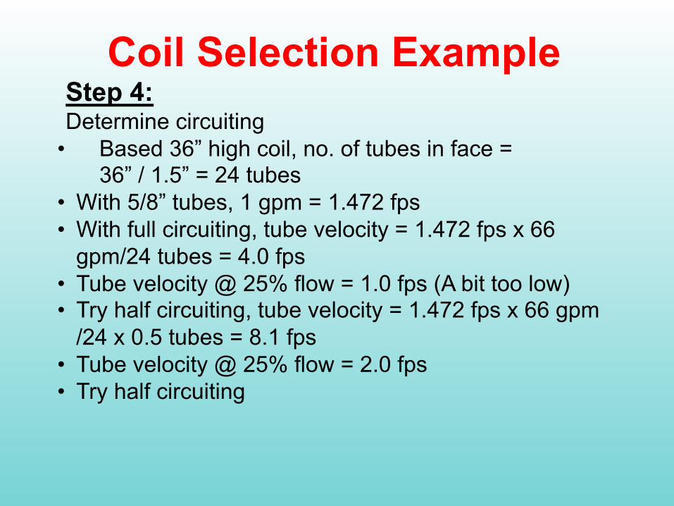
Coil Selection ExampleStep 4:Determine circuiting
• Based 36” high coil, no. of tubes in face = 36” / 1.5” = 24 tubes
• With 5/8” tubes, 1 gpm = 1.472 fps• With full circuiting, tube velocity = 1.472 fps x 66
gpm/24 tubes = 4.0 fps• Tube velocity @ 25% flow = 1.0 fps (A bit too low)• Try half circuiting, tube velocity = 1.472 fps x 66 gpm
/24 x 0.5 tubes = 8.1 fps• Tube velocity @ 25% flow = 2.0 fps • Try half circuiting

Coil Selection ExampleStep 5:Enter data:
• Airflow, EAT, EWT, water flow Input airflow, EAT, EWT, water flow
• COIL type, coil size• Select Materials
• 5/8” x 0.020” thick tubes• 6 rows, 10 fins/inch wave pattern• 0.006” fin thickness
• Circuiting: Half Circuited
Steps 6 & 7:• Run results and adjust inputs for desired tube
velocities and LATs at 100% and minimum airflow conditions
• Re-iterate as required
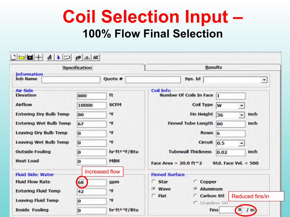
Coil Selection Input –100% Flow Final Selection
Increased flow
Reduced fins/in
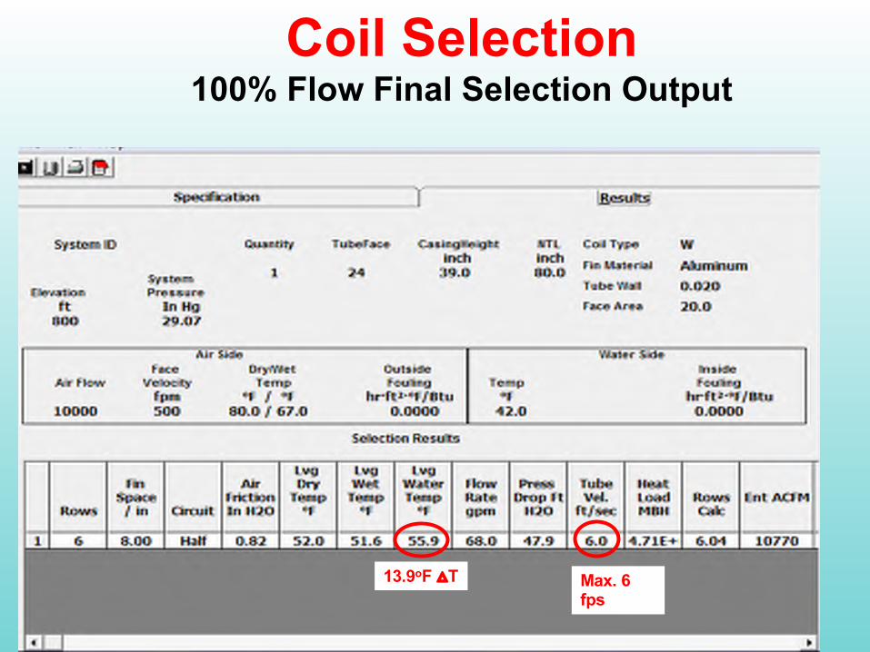
Coil Selection100% Flow Final Selection Output
13.9oF △T Max. 6 fps

Coil Selection40% Airflow and min. tube velocity
Final Selection Output
Min 1.5 fps18.5oF △T Load turndown = 33%
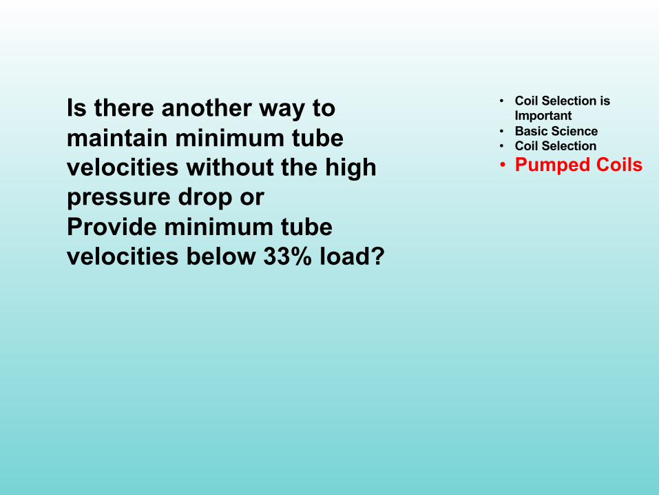
Is there another way to maintain minimum tube velocities without the high pressure drop orProvide minimum tube velocities below 33% load?
• Coil Selection is Important
• Basic Science• Coil Selection• Pumped Coils

Is there another way to maintain minimum tube velocities without the high pressure drop orProvide minimum tube velocities below 33% load?
YES! USING PUMPED COILS!
Coil pumps can be used to maintain minimum tube velocities, even when system flows vary.
• Coil Selection is Important
• Basic Science• Coil Selection• Pumped Coils
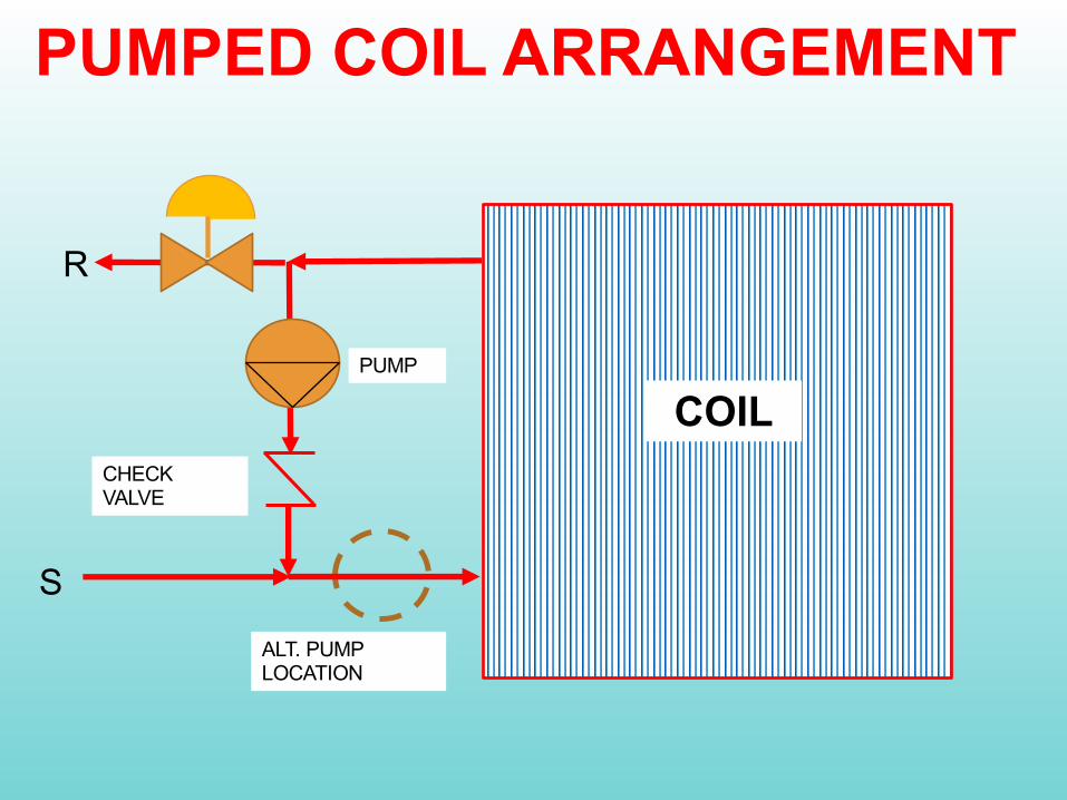
COILPUMP
ALT. PUMP LOCATION
CHECK VALVE
PUMPED COIL ARRANGEMENT
R
S
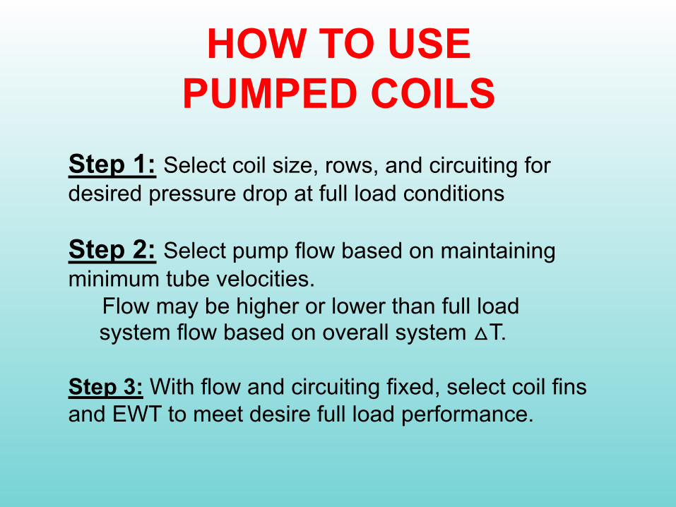
HOW TO USE PUMPED COILS
Step 1: Select coil size, rows, and circuiting for desired pressure drop at full load conditions
Step 2: Select pump flow based on maintaining minimum tube velocities.
Flow may be higher or lower than full load system flow based on overall system △T.
Step 3: With flow and circuiting fixed, select coil fins and EWT to meet desire full load performance.

HOW TO USE PUMPED COILS
Step 4: Use mixing equation to determine overall system flow, LWT, and △T.
Step 5: Select control valve based on system flow, not coil flow.

PUMPED COIL CONTROL
Q (BTUH) = U ● A ● LOG(△T/ △T)• U is fixed by maintaining tube velocity• Area is fixed by selecting coil size, tubing, and circuiting• Capacity is controlled by varying the LOG(△T/ △T) or
blending water temperatures up/down.

MIXING EQUATIONSYSTEM ENERGY = COIL
ENERGYQsys = GPMsys ● 500 ● (Tsys in - Tsys out)
Qcoil = GPMcoil ● 500 ● (Tcoil in - Tcoil out)
Tcoil out = Tsys out
GPMsys = GPMcoil (Tcoil in - Tcoil out)
(Tsys in - Tcoil out)

SAMPLE COIL SELECTION

SAMPLE COIL SELECTION @ 100% LOAD

SAMPLE COIL INPUTFOR 40% LOAD
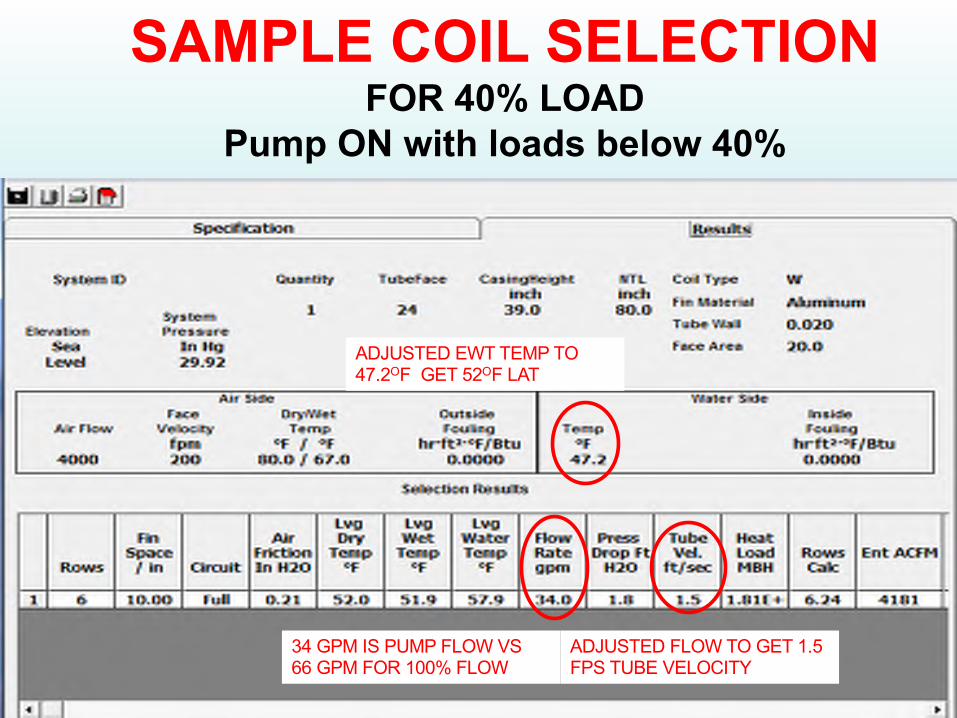
SAMPLE COIL SELECTION FOR 40% LOAD
Pump ON with loads below 40%
ADJUSTED FLOW TO GET 1.5 FPS TUBE VELOCITY
ADJUSTED EWT TEMP TO 47.2OF GET 52OF LAT
34 GPM IS PUMP FLOW VS66 GPM FOR 100% FLOW
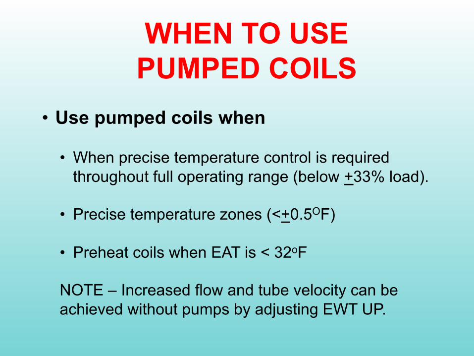
WHEN TO USE PUMPED COILS
• Use pumped coils when
• When precise temperature control is required throughout full operating range (below +33% load).
• Precise temperature zones (<+0.5OF)
• Preheat coils when EAT is < 32oF
NOTE – Increased flow and tube velocity can be achieved without pumps by adjusting EWT UP.
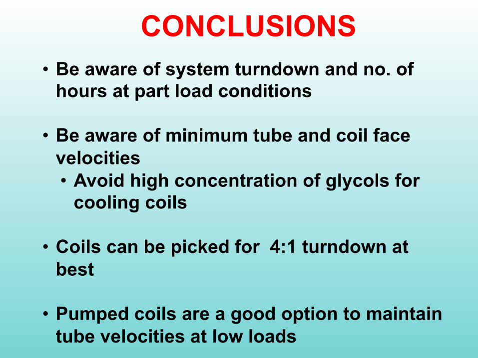
CONCLUSIONS• Be aware of system turndown and no. of
hours at part load conditions
• Be aware of minimum tube and coil face velocities• Avoid high concentration of glycols for
cooling coils
• Coils can be picked for 4:1 turndown at best
• Pumped coils are a good option to maintain tube velocities at low loads