advanced acoustic sensor technologies · zil m 60 brdm btr 80 bmp maz wheeled or tracked light or...
TRANSCRIPT
TTank-automotive & AArmaments COMCOMmand
Advanced Acoustic Sensor TechnologiesNDIA Symposium
Session III Advanced Technologies20 June 2001
Briefer: Jeffrey HeberleyTechnical Executive, FSAC, TACOM-ARDEC 1/n
Report Documentation Page
Report Date 20JUN2001
Report Type N/A
Dates Covered (from... to) -
Title and Subtitle Advanced Acoustic Sensor Technologies
Contract Number
Grant Number
Program Element Number
Author(s) Heberley, Jeffrey
Project Number
Task Number
Work Unit Number
Performing Organization Name(s) and Address(es) TACOM-ARDEC
Performing Organization Report Number
Sponsoring/Monitoring Agency Name(s) and Address(es) NDIA (National Defense Industrial Association 2111Wilson Blvd., Ste. 400 Arlington, VA 22201-3061
Sponsor/Monitor’s Acronym(s)
Sponsor/Monitor’s Report Number(s)
Distribution/Availability Statement Approved for public release, distribution unlimited
Supplementary Notes Proceedings from Armaments for the Army Transformation Conference, 18-20 June 2001 sponsored by NDIA
Abstract
Subject Terms
Report Classification unclassified
Classification of this page unclassified
Classification of Abstract unclassified
Limitation of Abstract UU
Number of Pages 36
OUTLINE• BACKGROUND
– WHY ACOUSTICS– TECHNOLOGY EXPLOITED– PRIOR ARDEC PROGRAMS
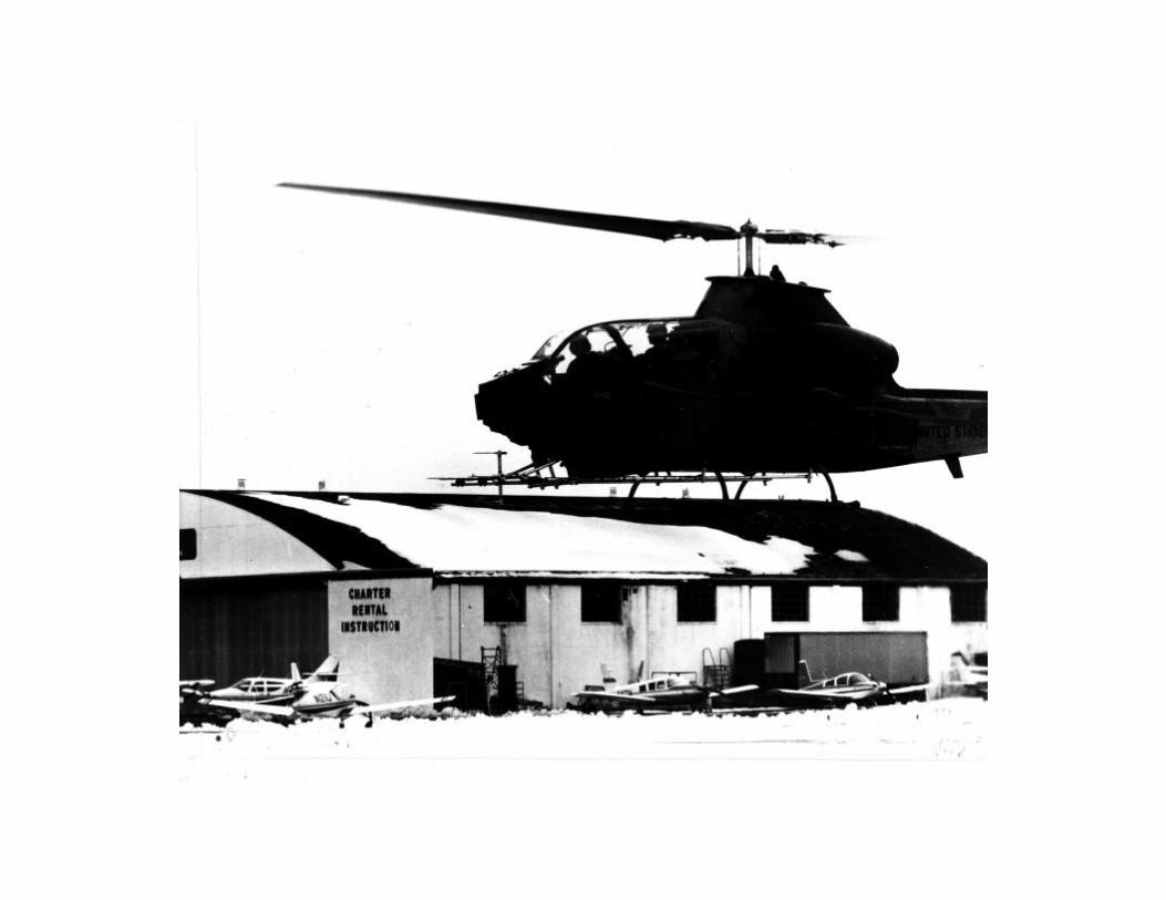
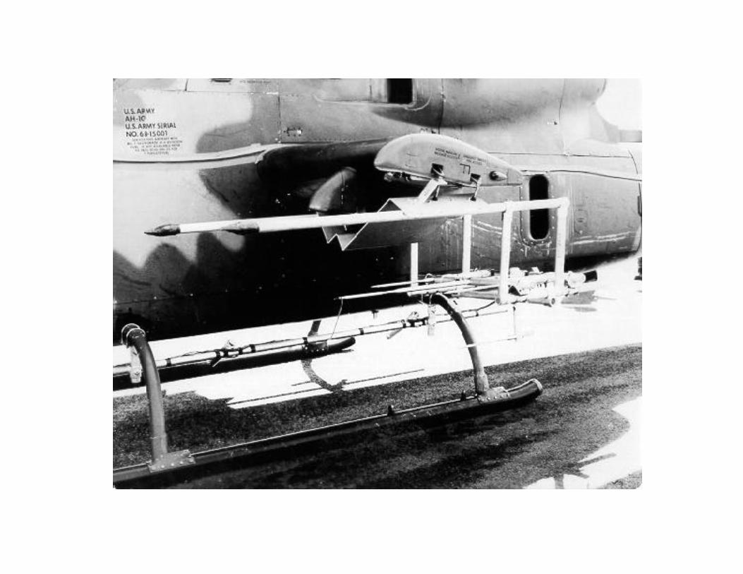
• PRIOR TECHNOLOGY/PROGRAMS– FAAD– HELO & BAT– COUNTER SNIPER– RFPI
• CURRENT TECHNOLOGY/PROGRAMS– NINOX– RAPTOR
• CLASSIFIER• TARGET COUNTER
– TECH BASE (6.2)• ACOUSTIC COUNTER BATTERY SYSTEM (ACBS)• ACOUSTIC/SEISMIC MODELING• NETWORKED DISTRIBUTED SENSORS

Army Benefits
• Passive• Day/Night/Adverse Weather• NLOS Threat Target Detection• NC-IFF, PHID (Avoids Fratricide)• Acquire Threats at Stand-off Ranges• Support Shoot-on-the-Move• Range to Target
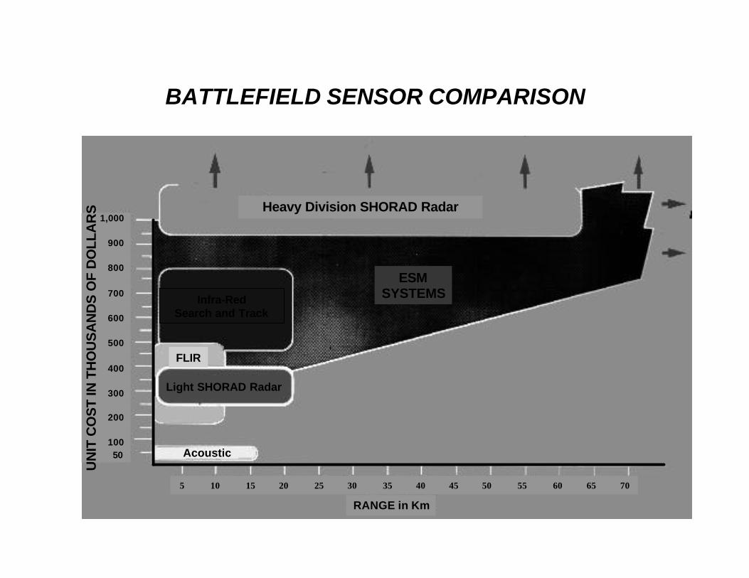
BATTLEFIELD SENSOR COMPARISON
ESMSYSTEMSInfra-Red
Search and Track
FLIR
Light SHORAD Radar
Acoustic
5 10 15 20 25 30 35 40 45 50 55 60 65 70
1,000
900
800
700
600
500
400
300
200
10050
UN
IT C
OS
T IN
TH
OU
SA
ND
S O
F D
OLL
AR
S Heavy Division SHORAD Radar
RANGE in Km

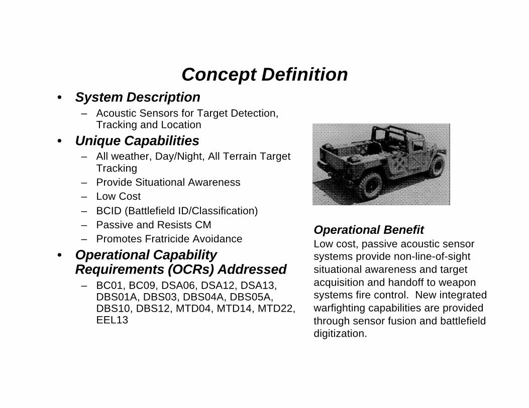
Concept Definition• System Description
– Acoustic Sensors for Target Detection,Tracking and Location
• Unique Capabilities– All weather, Day/Night, All Terrain Target
Tracking– Provide Situational Awareness– Low Cost– BCID (Battlefield ID/Classification)– Passive and Resists CM– Promotes Fratricide Avoidance
• Operational CapabilityRequirements (OCRs) Addressed
– BC01, BC09, DSA06, DSA12, DSA13,DBS01A, DBS03, DBS04A, DBS05A,DBS10, DBS12, MTD04, MTD14, MTD22,EEL13
Operational BenefitLow cost, passive acoustic sensorsystems provide non-line-of-sightsituational awareness and targetacquisition and handoff to weaponsystems fire control. New integratedwarfighting capabilities are provided through sensor fusion and battlefielddigitization.

BBN-12 Channel Acoustic HelmetBBN-12 Channel Acoustic HelmetHeading SensorHeading Sensor
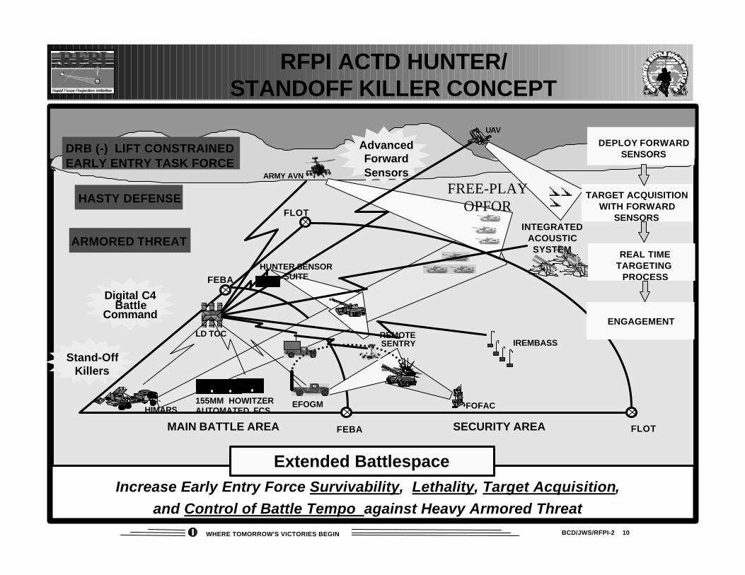
BCD/JWS/RFPI-2 10WHERE TOMORROW'S VICTORIES BEGIN
Increase Early Entry Force Survivability, Lethality, Target Acquisition,and Control of Battle Tempo against Heavy Armored Threat
RFPI ACTD HUNTER/STANDOFF KILLER CONCEPT
HIMARS155MM HOWITZERAUTOMATED FCS
Digital C4Battle
Command
FOFAC
FEBA
FLOT
FLOTFEBA
Extended Battlespace
Stand-OffKillers
AdvancedForwardSensors
MAIN BATTLE AREA SECURITY AREA
EFOGM
DEPLOY FORWARDSENSORS
TARGET ACQUISITIONWITH FORWARD
SENSORS
ENGAGEMENT
ARMY AVN
DRB (-) LIFT CONSTRAINEDEARLY ENTRY TASK FORCE
HASTY DEFENSE
ARMORED THREAT
UAV
IREMBASS
REAL TIMETARGETING
PROCESS
INTEGRATEDACOUSTICSYSTEM
FREE-PLAYOPFOR
LD TOC REMOTE SENTRY
HUNTER SENSORSUITE
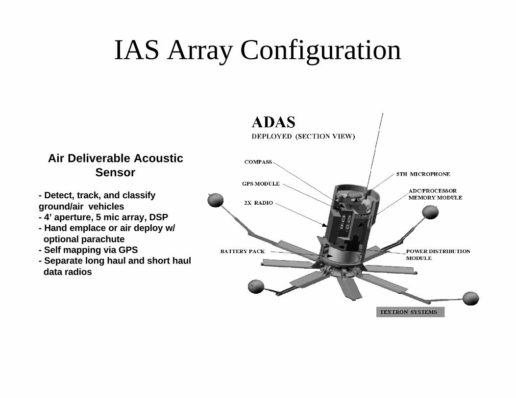
IAS Array Configuration
Air Deliverable AcousticSensor
- Detect, track, and classifyground/air vehicles- 4’ aperture, 5 mic array, DSP- Hand emplace or air deploy w/ optional parachute- Self mapping via GPS- Separate long haul and short haul data radios
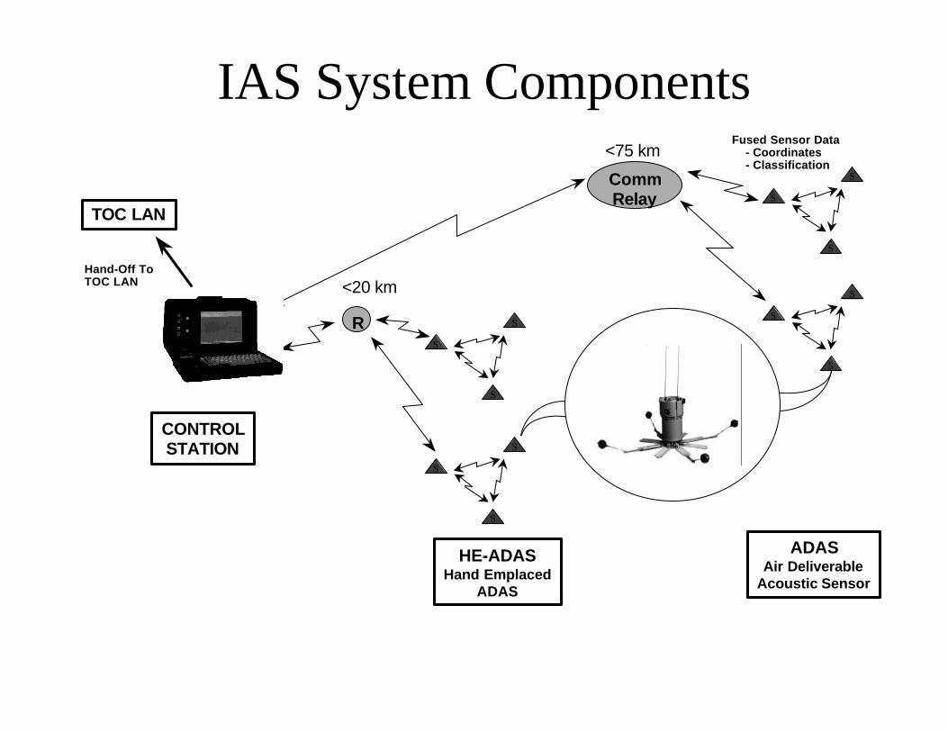
IAS System Components
CONTROLSTATION
TOC LAN
ADASAir Deliverable
Acoustic Sensor
HE-ADASHand Emplaced
ADAS
CommRelay
<75 km
S
S
S
S
S
S
S
S
S
<20 km
S
S
S
R
Hand-Off ToTOC LAN
Fused Sensor Data - Coordinates - Classification

Acoustic CRADA (TSD & ARDEC)ARDEC to develop improved air-acoustic signal processing techniques for IAS/ADAS
•Advanced detection & classification methods
•Field test facility support (ADAS units, site, drivers, etc.)
•GFE ADAS units for Operational Testing
•Textron to support & implement
•Tech support & consultation to above tasks
•Provide GDAS to ARDEC for Development Testing
•Implement ARDEC algo improvements in ADAS S/W
•Field test support (personnel, met, truth, etc.)

Compelling Australian Need
* Alice Springs
* Sydney
* Brisbane
* Melbourne
Adelaide * * Canberra
Perth *
Australian Army<25,000 Total
Ninox UGS
70 sites in the Northfunded in current program~$20-33M US
Eventual requirementmay exceed 1000 sites >$200M US
* Darwin
Pop. >150M
Pop. 0.7M
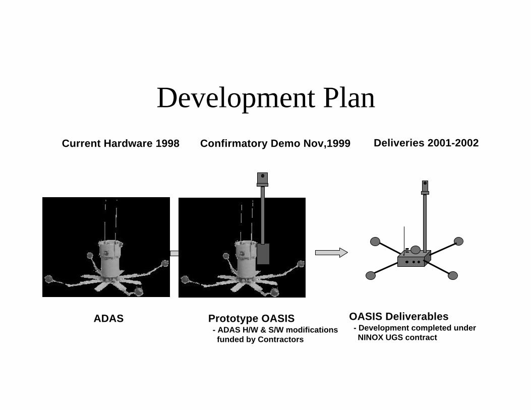
Development Plan
ADAS Prototype OASIS - ADAS H/W & S/W modifications funded by Contractors
Confirmatory Demo Nov,1999
OASIS Deliverables - Development completed under NINOX UGS contract
Current Hardware 1998 Deliveries 2001-2002

Some Key Features• Beamforming Acoustic Array (TSD)
• Long Range Discrimination & Tracking of Motor Vehicles
• Distributed Mini-Sensors (RACAL->Thompson->THALES)
• Seismic, Magnetic, & Passive Infrared• Personnel Detection & Back-Up for Acoustics
• Precision Cued Day/Night Electro-Optics (TENIX)
• Operator in the Loop Target Recognition
• Satellite Based Long Haul Communications• Operation in Remote Areas - Unlimited Range
• Advanced Integrated Control Station• Remote Situational Awareness

Terrain Commander
OASIS - Optical Acoustic SATCOM Integrated Sensor
- OASIS Day/Night Electro-Optics Head
- Rucksack
- Central Monitoring Facility (CMF)
- OASIS Base Unit w/ 5 Mic Beamforming Acoustic Sensor & Satellite Comms.
- CLASSIC 2000 Seismic, Magnetic, Passive Infrared, & Monitor
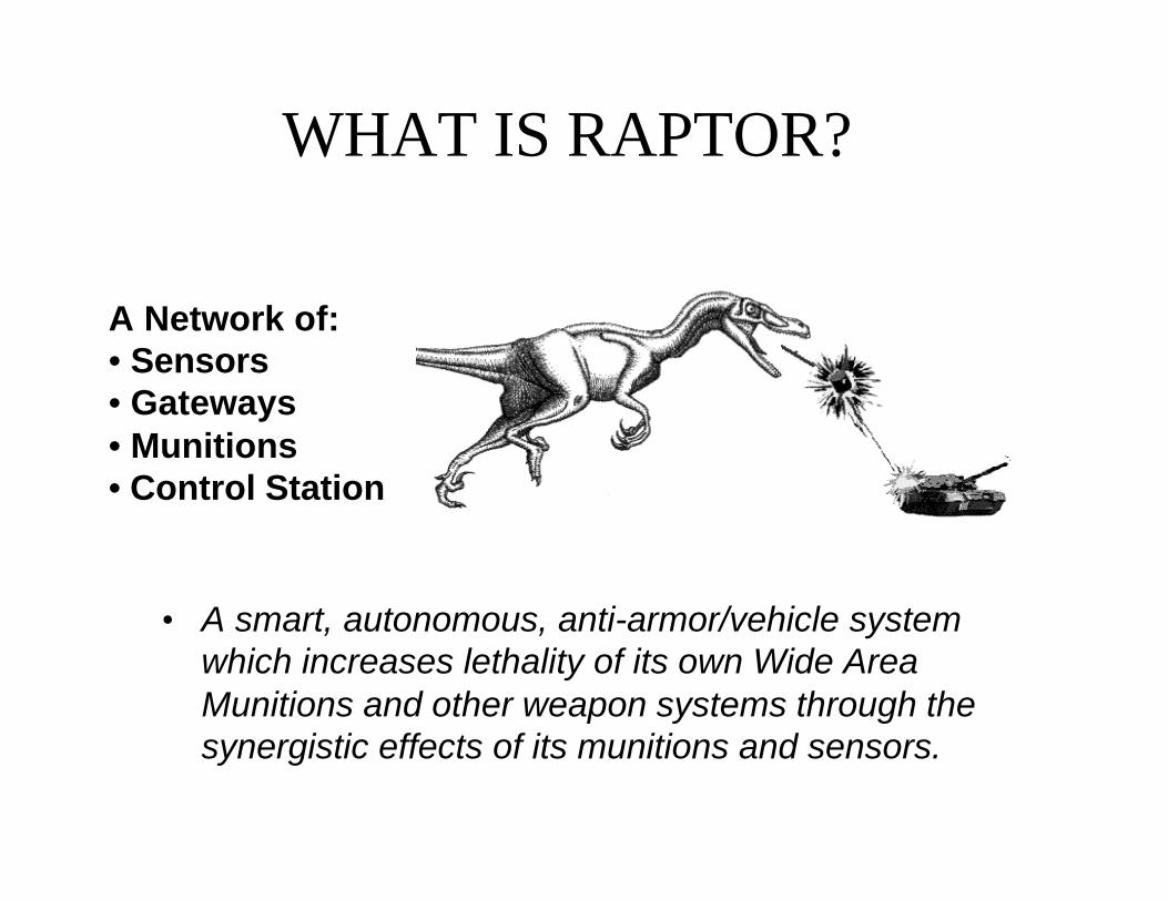
WHAT IS RAPTOR?
• A smart, autonomous, anti-armor/vehicle systemwhich increases lethality of its own Wide AreaMunitions and other weapon systems through thesynergistic effects of its munitions and sensors.
A Network of:• Sensors• Gateways• Munitions• Control Station

CORE RAPTOR
• Remote Employment⇒ Up to 50 Kilometers from Control
Station⇒ Delivered by Helicopter, Hand
Emplaced
• Extended Communications⇒ Multiple Ground and/or Aerial
Communication Relay
• Targets (detect, classify, track/locate,attack) – MUTIPLE TARGETS⇒ Heavy Wheeled and Tracked⇒ Light Wheeled and Tracked
An Early Operational Capabilityfor the Brigade Commander
X
III
•
GCS
Hornet PIP
30 - 50 km
ADAS
•
Gateway
A Force XXI System

Current UGS Functions/Features• Autonomous sensor networks
deployed in clusters• GPS, Compass, Radios• DSP hardware/software• Detection, Multiple Target
Tracking, Classification• Master/Slave Data Fusion• Early Warning for Munitions &
TOC• Target Info for Long Range
Shooters/Hunters
Committed to Excellence
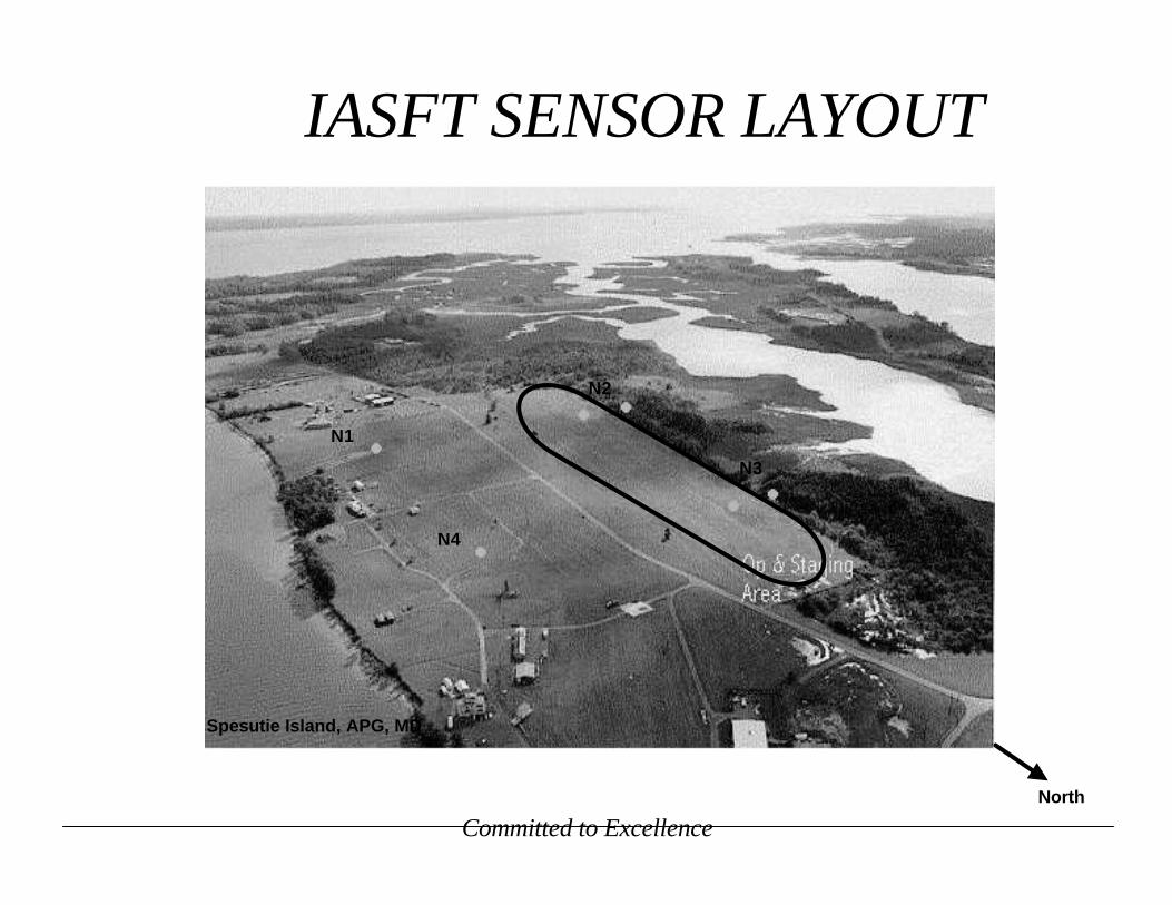
IASFT SENSOR LAYOUT
Spesutie Island, APG, MD
N1
N2
N3
N4
North
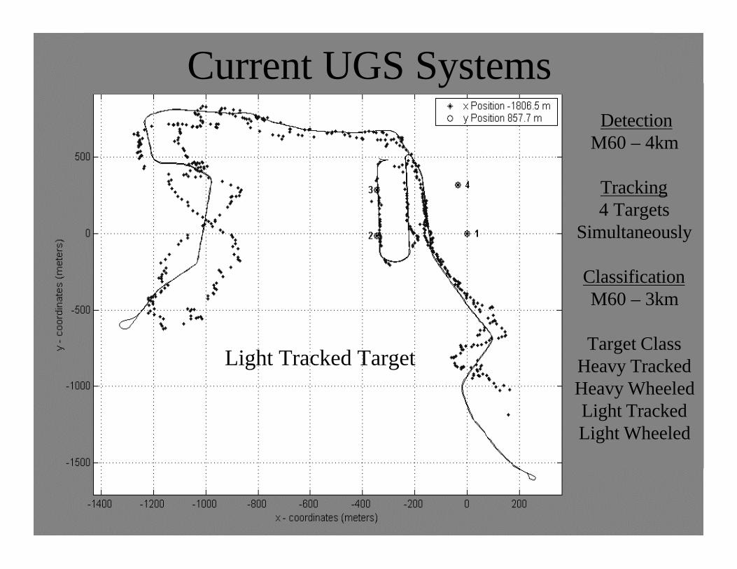
Current UGS Systems
Light Tracked Target
DetectionM60 – 4km
Tracking4 Targets
Simultaneously
ClassificationM60 – 3km
Target ClassHeavy TrackedHeavy WheeledLight TrackedLight Wheeled
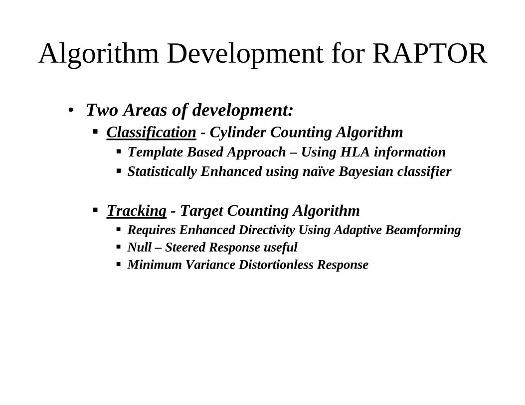
• Two Areas of development:§ Classification - Cylinder Counting Algorithm§ Template Based Approach – Using HLA information§ Statistically Enhanced using naïve Bayesian classifier
§ Tracking - Target Counting Algorithm§ Requires Enhanced Directivity Using Adaptive Beamforming§ Null – Steered Response useful§ Minimum Variance Distortionless Response
Algorithm Development for RAPTOR
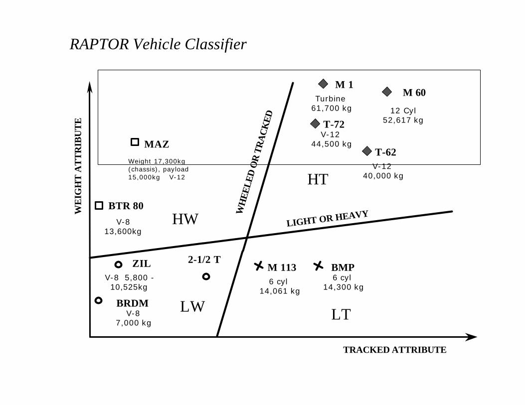
RAPTOR Vehicle Classifier
WE
IGH
T A
TT
RIB
UT
E
TRACKED ATTRIBUTE
T-72
T-62
ZIL
M 60
BRDM
BTR 80
BMP
MAZ
WH
EELE
D O
R T
RA
CK
ED
LIGHT OR HEAVY
LW
HW
LT
HT
M 1
2-1/2 TM 113
V-813,600kg
Weight 17,300kg(chassis), payload15,000kg V-12
V-8 5,800 -10,525kg
V-12 44,500 kg
V-12 40,000 kg
12 Cyl52,617 kg
6 cyl 14,061 kg
V-87,000 kg
6 cyl 14,300 kg
Turbine 61,700 kg
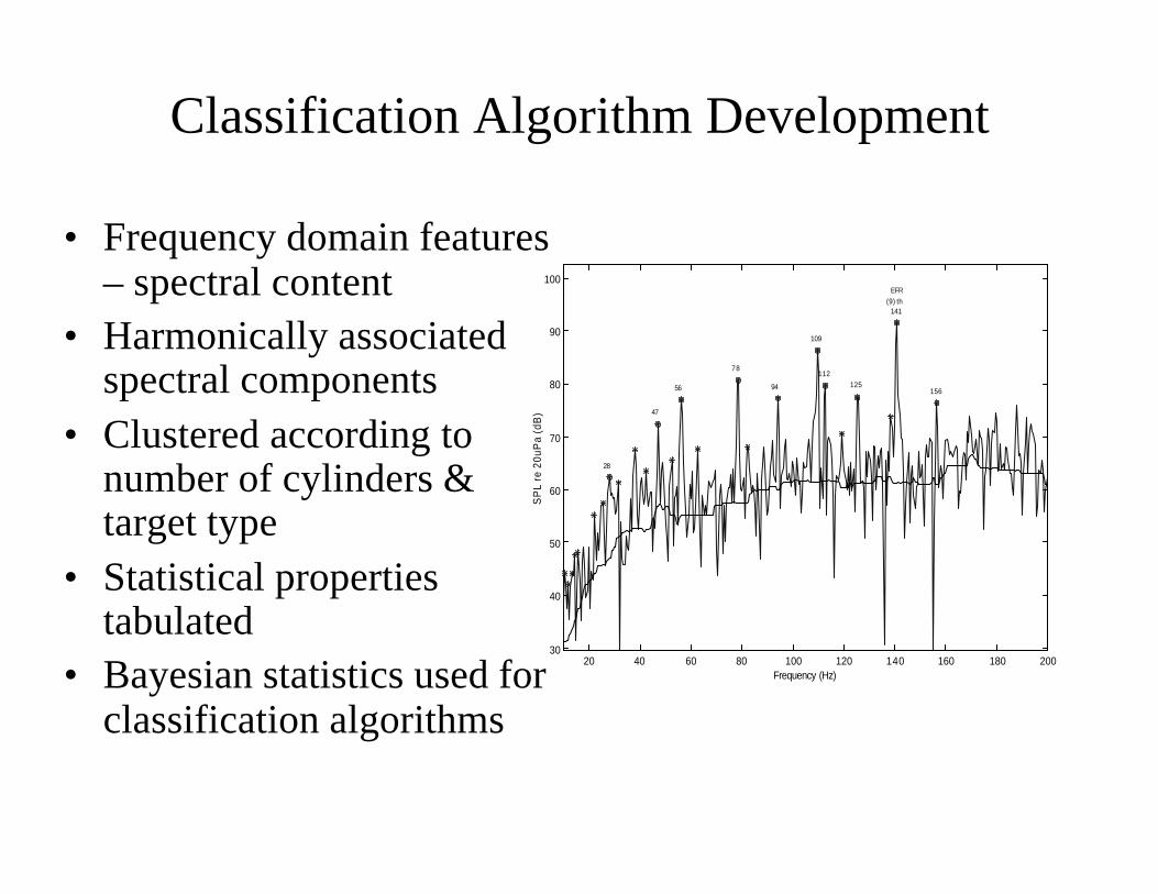
Classification Algorithm Development
20 40 60 80 100 120 140 160 180 20030
40
50
60
70
80
90
100
28
47
56
78
94
109
112125
141
156
EFR(9) th
Frequency (Hz)
SP
L re
20u
Pa
(dB
)
• Frequency domain features– spectral content
• Harmonically associatedspectral components
• Clustered according tonumber of cylinders &target type
• Statistical propertiestabulated
• Bayesian statistics used forclassification algorithms
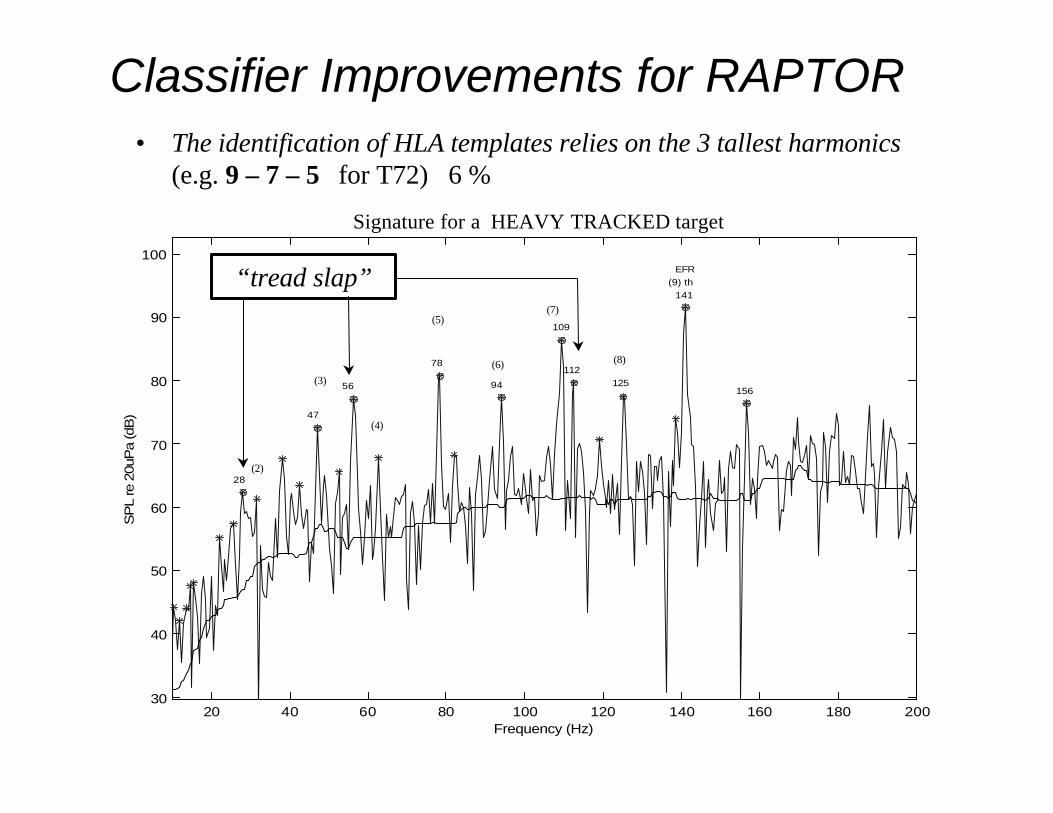
• The identification of HLA templates relies on the 3 tallest harmonics(e.g. 9 – 7 – 5 for T72) 6 %
20 40 60 80 100 120 140 160 180 20030
40
50
60
70
80
90
100
28
47
56
78
94
109
112125
141
156
EFR(9) th
Frequency (Hz)
SP
L re
20u
Pa
(dB
)
(8)
(7)
(6)
(5)
(4)
(3)
(2)
Signature for a HEAVY TRACKED target
Classifier Improvements for RAPTOR
“tread slap”

Cylinder Counting Algorithm
Load signaturefrom file
FFT
ObtainSpectrum
20 40 60 80 100 120 140 160 180 20030
40
50
60
70
80
90
100
2 8
47
56
78
94
1 0 9
112125
141
1 5 6
EFR(9) th
Frequency (Hz)
SP
L re
20u
Pa
(dB
)
Median Filter
Identify Peaks > 10dBCalculate
Noise Floor
Determine EFRPerform HLA
Tallest PeakGroup
HarmonicallyRelated Peaks
Retain 3Tallest Peaks
EstimateNumber ofCylinders
PerformTemplate
Match
TemplateDatabase
DatabaseCompare
Extract Features
CylinderAttribute
Discrimination Classification

Classification Algorithm Results
0
0.1
0.2
0.3
0.4
0.5
0.6
0.7
0.8
0.9
1
Training Set All Runs Runs not in Set
Cylinder Classification over all WAM data
92
85
79
89 89 91
86
92
83
99 99
6 8 12 Turbine
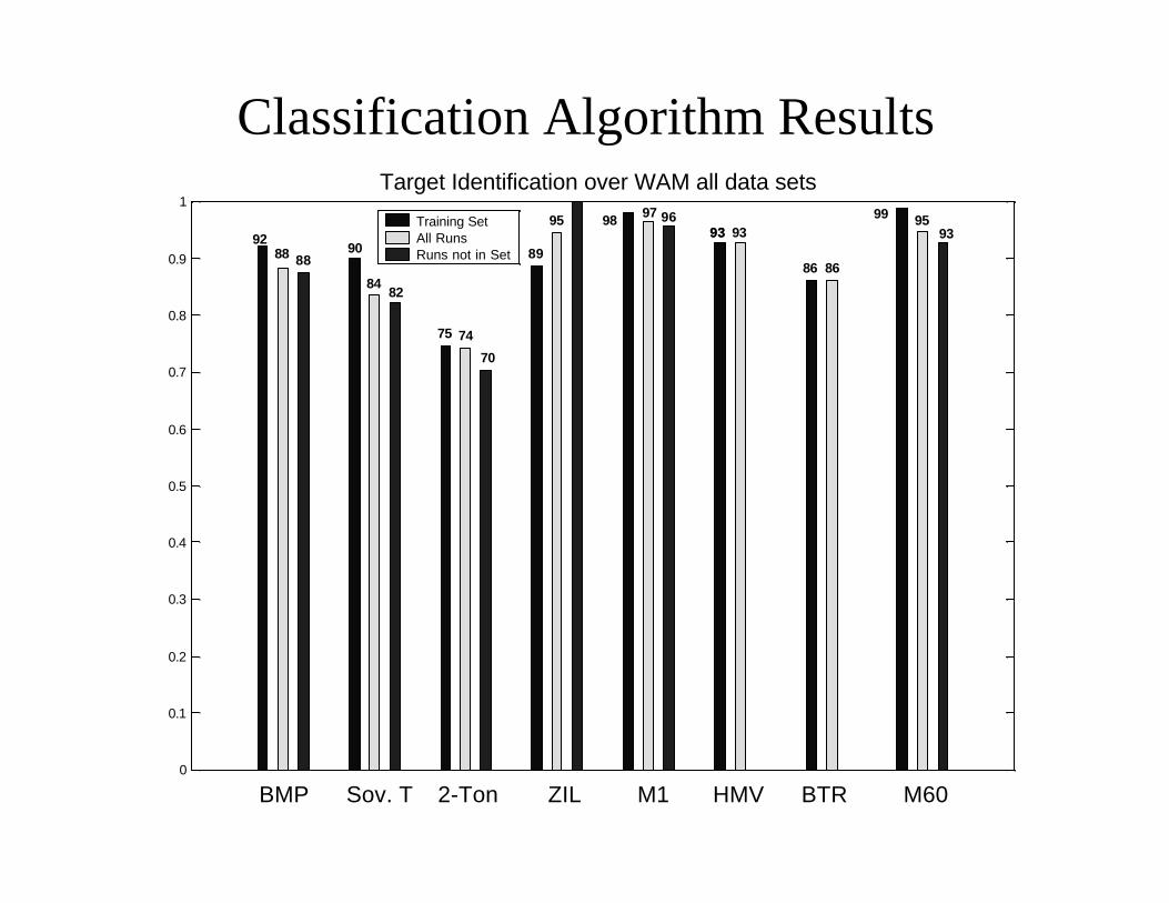
Classification Algorithm Results
0
0.1
0.2
0.3
0.4
0.5
0.6
0.7
0.8
0.9
1Target Identification over WAM all data sets
Training Set All Runs Runs not in Set
BMP Sov. T 2-Ton ZIL M1 HMV BTR M60
92 88 88
90
84 82
75 74
70
89
95 98 97 96 93 93 93
86 86
99 95 93
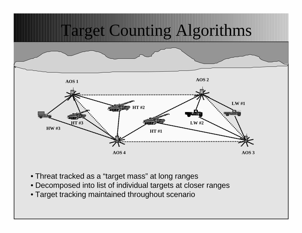
Target Counting Algorithms
• Threat tracked as a “target mass” at long ranges• Decomposed into list of individual targets at closer ranges• Target tracking maintained throughout scenario
LW #1
LW #2
HT #1
HT #2
HT #3HW #3
AOS 1 AOS 2
AOS 3AOS 4
• Preliminaries§ Requires superior bearing resolution§ MATLAB program to test beams for different
array geometries and apertures§ Try adaptive beamforming methods to check the
feasibility of assumptions made§ Nullsteering, Optimal Beamformer response is
determined as weights are obtained§ MVDR solution
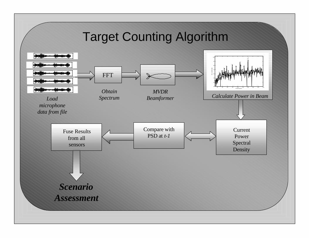
Target Counting Algorithm
Target Counting Algorithm
Loadmicrophone
data from file
FFT
ObtainSpectrum
20 40 60 80 100 120 140 160 180 20030
40
50
60
70
80
90
100
2 8
47
56
78
94
1 0 9
112125
141
1 5 6
EFR(9) th
Frequency (Hz)
SP
L re
20u
Pa
(dB
)
Calculate Power in BeamMVDR
Beamformer
CurrentPower
SpectralDensity
Compare withPSD at t-1
ScenarioAssessment
Fuse Resultsfrom allsensors
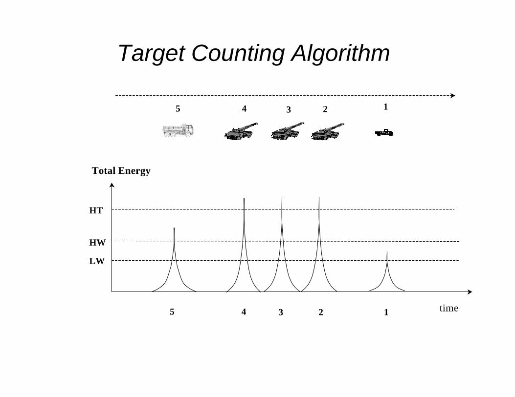
Target Counting Algorithm
12345
12345
time
LW
HW
HT
Total Energy
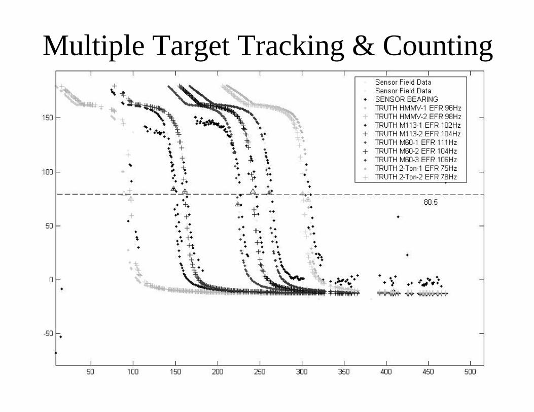
Multiple Target Tracking & Counting
Summary
• Algorithm Development usingMATLAB/SIMULINK
• Extensive Signature Databases w/ GroundTruth
• Sensor Hardware / MATLAB models– IAS Overwatch Sensor– Wide Area Munition (WAM)Sensor
• Currently working on– Target Classification– Multiple Target Tracking