advance scc-c operator s manual - abb group · advance scc-c sample gas cooler applications and ......
TRANSCRIPT

Advance SCC-C Sample Gas Cooler
Operator’s Manual 42/23-55-0 EN


42/23-55-0 EN Advance SCC-C Sample Gas Cooler Operator’s Manual 3
Contents
Page
Preface 4General Safety Information 5Safety Tips for Handling Electronic Measurement Devices 6
Chapter 1 Sample Gas Cooler Installation and Start-Up 7
Normal Operation 7Requirements for the Installation Site 7Sample Gas Cooler Unpacking 8Dimensional Drawing 9Sample Gas Cooler Installation 10Sample Gas and Condensate Pipe Connection 11Power Supply Wiring Connection 12Power Supply Activation, Lead Time 13
Chapter 2 Maintenance 14
Removing and Installing Heat Exchangers 14Replacing Peristaltic Pump Hoses 16Replacing Peristaltic Pump Pressure Rollers and Springs 18Clean Condenser Fins 20Troubleshooting 21
Chapter 3 Sample Gas Cooler Shutdown and Packing 22
Sample Gas Cooler Shutdown 22Sample Gas Cooler Packing 23
Appendix 24
Advance SCC-C Sample Gas Cooler Applications and Functions 24Description 25Operating Specifications 27
4 Advance SCC-C Sample Gas Cooler Operator’s Manual 42/23-55-0 EN
Preface
Contents of thisOperator’s Manual
This operator's manual contains all the information you need to install, commission,operate and maintain the Advance SCC-C sample gas cooler safely and inaccordance with the regulations.
This operator's manual contains information on all the function units of the samplegas cooler. It is possible that the sample gas cooler that you have been suppliedwith could differ from the model described here.
Title Document No.AdditionalDocuments Specification Sheet
"System Components for Sample Gas Conditioning" 10/23-5.20 EN
This publication can be ordered from your authorized ABB Automationrepresentative or from
ABB Automation Products GmbH, Marketing Communication,Fax: +49-69-79 30-45 66, E-mail: [email protected]
Further Details on theInternet
You can find further information on ABB Analytical products and services on theinternet: "http://www.abb.de/analytical".
Text FormatInformation
1, 2, 3, ... Indicates reference numbers in the figures.
Symbols in thisManual
Some symbols identify special information text:
Identifies specific information on operation of the sample gas cooler as wellas on the use of this manual.
Identifies safety information to be heeded during sample gas cooleroperation in order to avoid risks to the operator.
This operator’s manual is protected by copyright. The translation, duplication and distribution in any form,even in a revised edition or in extracts, in particular as a reprint, by photomechanical or electronic repro-duction or in the form of storage in data processing systems or data networks are prohibited without theconsent of the copyright holder and will be prosecuted under civil and criminal law.
42/23-55-0 EN Advance SCC-C Sample Gas Cooler Operator’s Manual 5
General Safety Information
Requirements forSafe Operation
In order to operate in a safe and efficient manner the sample gas cooler should beproperly handled and stored, correctly installed and started, properly operated andcorrectly maintained.
PersonnelQualifications
Only persons familiar with the installation, set-up, operation and maintenance ofcomparable equipment and certified as being capable of such work should workon the sample gas cooler.
Special Informationand Precautions
It is important to comply with:• The content of this operator's manual• The safety information affixed to the sample gas cooler• The applicable safety precautions for installing and operating electrical devices• Safety precautions for working with gases, acids, condensates, etc.
National Regulations The regulations, standards and guidelines cited in this operator's manual areapplicable in the Federal Republic of Germany. The applicable national regulationsshould be followed when the sample gas cooler is used in other countries.
Sample Gas CoolerSafety and SafeOperation
The sample gas cooler is designed and tested in accordance with DIN EN 61010Part 1/ IEC 1010-1, "Safety Provisions for Electrical Measuring, Control, Regulationand Laboratory Instruments" and has been shipped ready for safe operation.
To maintain this condition and to assure safe operation, read and follow the safetyinformation identified with the symbol in this manual. Failure to do so can putpersons at risk and can lead to sample gas cooler damage as well as damage toother systems and instruments.
AdditionalInformation
If the information in this operator's manual does not cover a particular situation,ABB Automation Service is prepared to supply additional information as needed.
Contact your local ABB Automation service representative or
ABB Automation Systems GmbH, P.O.Box 93 02 09, D-60457 Frankfurt, GermanyTel: +49-69-79 30-46 00, Fax: +49-69-79 30-46 01,E-mail: [email protected]

6 Advance SCC-C Sample Gas Cooler Operator’s Manual 42/23-55-0 EN
Safety Tips for Handling Electronic Measurement Devices
Protective LeadConnection
The protective lead should be attached to the protective lead connector beforeany other connection is made.
Risks of Loss ofProtective LeadContinuity
The sample gas cooler can be hazardous if the protective lead is interrupted insideor outside the sample gas cooler or if the protective lead is disconnected.
Proper OperatingVoltage
The sample gas cooler voltage must be set to match the line voltage before thepower supply is activated.
Risks Involved inOpening the Covers
Current-bearing components can be exposed when the covers or parts areremoved, even if this can be done without tools. Current can be present at someconnection points.
Risks Involved inWorking with an OpenSample Gas Cooler
The sample gas cooler must be disconnected from all power sources before anymaintenance work is performed. Work on a sample gas cooler that is open andconnected to power should only be performed by trained personnel who arefamiliar with the risks involved.
Charged Capacitors The sample gas cooler capacitors can retain their charge even when the unit isdisconnected from all power sources.
Use of Proper Fuses Only fuses of the specified type and rated current should be used asreplacements. Never use patched fuses. Do not short-circuit the fuseholdercontacts.
When Safe Operationcan no Longer beAssured
If it is apparent that safe operation is no longer possible, the sample gas coolershould be taken out of operation and secured against unauthorized use.
The possibility of safe operation is excluded:• If the sample gas cooler is visibly damaged• If the sample gas cooler is no longer operational• After prolonged storage under adverse conditions• After severe transport stresses

42/23-55-0 EN Advance SCC-C Sample Gas Cooler Operator’s Manual 7
Chapter 1 Sample Gas Cooler Installation and Start-Up
Normal Operation
Normal Operation The Advance SCC-C sample gas cooler is designed for cooling the sample gas, forseparating and removing the condensate.
The Advance SCC-C sample gas cooler must not be used in hazardous areas. Themodel of sample gas cooler featuring stainless-steel heat exchangers is suitable foruse with combustible sample gases.
Requirements for the Installation Site
Short Gas Paths The sample gas cooler should be installed as close as possible to the analysissystem.
Adequate AirCirculation
Ensure adequate natural air circulation around the sample gas cooler. Avoid heataccumulation.
Protection againstAdverseEnvironmentalConditions
The sample gas cooler should be protected from• cold,• radiated heat, e.g. from the sun, kilns or boilers,• temperature fluctuations,• strong air movement,• dust deposits and dust penetration,• corrosive atmosphere,• vibration.
Climatic Conditions Ambient temperature During operation: +10...+50 °CStorage and transport: –25...+60 °C
Relative humidity ≤ 75 % year-round average, ≤ 95 % on 30 days per year,occasional light condensation permissible
8 Advance SCC-C Sample Gas Cooler Operator’s Manual 42/23-55-0 EN
Sample Gas Cooler Unpacking
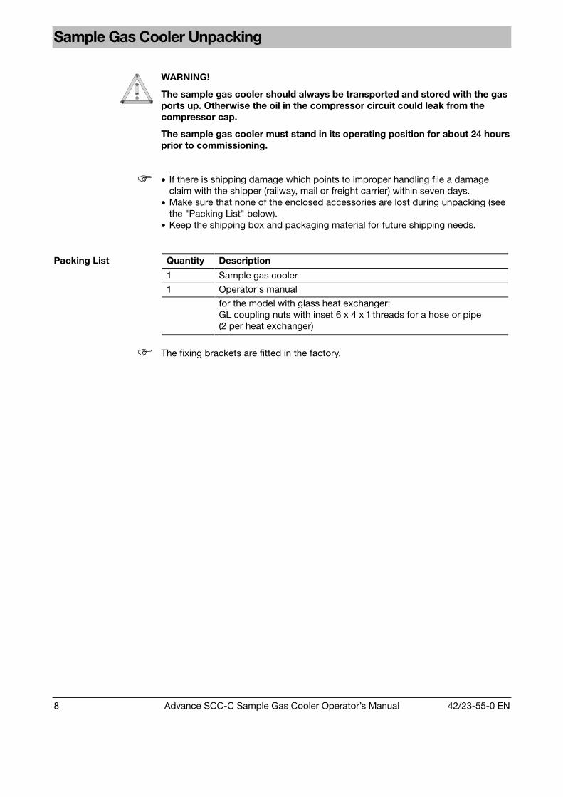
WARNING!
The sample gas cooler should always be transported and stored with the gasports up. Otherwise the oil in the compressor circuit could leak from thecompressor cap.
The sample gas cooler must stand in its operating position for about 24 hoursprior to commissioning.
• If there is shipping damage which points to improper handling file a damageclaim with the shipper (railway, mail or freight carrier) within seven days.
• Make sure that none of the enclosed accessories are lost during unpacking (seethe "Packing List" below).
• Keep the shipping box and packaging material for future shipping needs.
Quantity Description
1 Sample gas cooler
1 Operator's manual
Packing List
for the model with glass heat exchanger:GL coupling nuts with inset 6 x 4 x 1 threads for a hose or pipe(2 per heat exchanger)
The fixing brackets are fitted in the factory.

42/23-55-0 EN Advance SCC-C Sample Gas Cooler Operator’s Manual 9
Dimensional Drawing
Fig. 1
Dimensional Drawing
(Dimensions in mm)
13
266
220
301.
5
46
246
263
37.8
190.
5
1
2
3
4
1 Temperature Controller2 Condensate Outlet (in the Model with Peristaltic Pumps)3 Heat Exchanger Sample Gas Connections4 Passages for the (Fixed) Electrical Connections
You must take the additional space requirement into account• Adjacent to the instrument on the right-hand side for the cooling air inlet, and in
front of the instrument for the cooling air outlet (approx. 10 cm in each case),• in front of and underneath the instrument for connecting the condensate pipes
and• above the instrument for connecting the sample gas lines and the electrical
leads.
The fixing brackets are fitted in the factory, with about 2.5 cm projection to the rearwall.
Slope max. 5°.
10 Advance SCC-C Sample Gas Cooler Operator’s Manual 42/23-55-0 EN
Sample Gas Cooler Installation
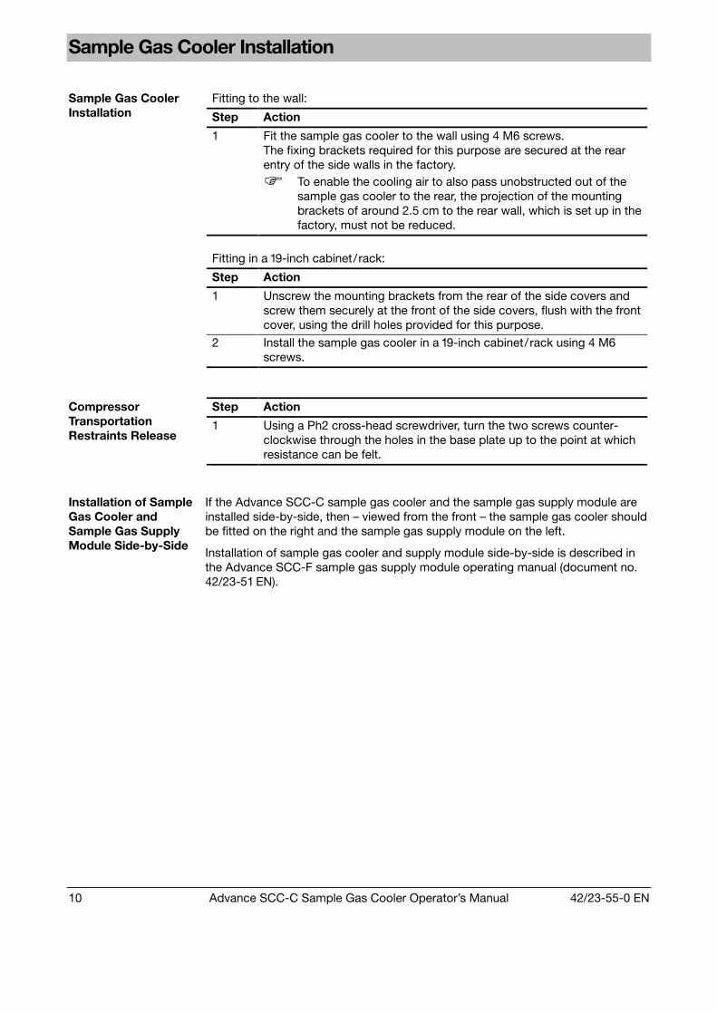
Fitting to the wall:
Step Action
Sample Gas CoolerInstallation
1 Fit the sample gas cooler to the wall using 4 M6 screws.The fixing brackets required for this purpose are secured at the rearentry of the side walls in the factory.
To enable the cooling air to also pass unobstructed out of thesample gas cooler to the rear, the projection of the mountingbrackets of around 2.5 cm to the rear wall, which is set up in thefactory, must not be reduced.
Fitting in a 19-inch cabinet/rack:
Step Action
1 Unscrew the mounting brackets from the rear of the side covers andscrew them securely at the front of the side covers, flush with the frontcover, using the drill holes provided for this purpose.
2 Install the sample gas cooler in a 19-inch cabinet/rack using 4 M6screws.
Step ActionCompressorTransportationRestraints Release
1 Using a Ph2 cross-head screwdriver, turn the two screws counter-clockwise through the holes in the base plate up to the point at whichresistance can be felt.
Installation of SampleGas Cooler andSample Gas SupplyModule Side-by-Side
If the Advance SCC-C sample gas cooler and the sample gas supply module areinstalled side-by-side, then – viewed from the front – the sample gas cooler shouldbe fitted on the right and the sample gas supply module on the left.
Installation of sample gas cooler and supply module side-by-side is described inthe Advance SCC-F sample gas supply module operating manual (document no.42/23-51 EN).

42/23-55-0 EN Advance SCC-C Sample Gas Cooler Operator’s Manual 11
Sample Gas and Condensate Pipe Connection
Condensate OutletHeat ExchangerMaterial
Sample Gas Inletsand Outlets Heat Exchanger Peristaltic Pump
Glass Hose/pipe thread6 x 4 x 1 mm
Pipe nipple14 x 12 x 1 mm
DN 4/6 mm
PVDF Pipe 6 x 1 mm G 3/8 inch DN 4/6 mm
Sample Gas andCondensate PipeConnection
Stainless steel Pipe 6 x 1 mm G 3/8 inch DN 4/6 mm
Sample Gas PipeConnection
Connect sample gas pipes to the sample gas inlets and outlets on the top side ofthe heat exchangers. The sample gas pipes should be made from material that issuited to the measuring task.
• The connections for sample gas inlet and outlet must be connected the rightway round. The connections are identified by arrows on the heat exchangers.
• Glass heat exchangers: Before fitting the GL coupling nuts you should checkthat the PTFE/silicone compression fittings are not damaged. The compressionfittings should be fitted with their white PTFE surface facing the glass.
• PVDF and stainless-steel heat exchangers: Screw suitably-sized pipe/hoseconnectors onto the pipe nipples.
• Make sure that the compression fittings and sealing rings are assembled in theright order
• When tightening the screw joints you should relieve the strain on the connectionpieces, for example by using a spanner to counteract the rotation. Failure toprotect the connection pieces in this way may result in them twisting and theseals consequently being impaired.
• It is important to observe the sample gas inlet conditions (see page 27,"Operating data").
Condensate PipeConnection
Connect the condensate pipe to the condensate outlet on the heat exchanger orperistaltic pump.
• Glass heat exchangers: Before fitting the GL coupling nuts you should checkthat the PTFE/silicone compression fittings are not damaged. The compressionfittings should be fitted with their white PTFE surface facing the glass.
• PVDF and stainless-steel heat exchangers: Screw in a suitably-sized pipe/hosescrew connection. Only use screw connections conforming to DIN 2999/1 with atapered R thread in conjunction with a suitable sealing tape/sealing fluid.
• Peristaltic pump:Connect the condensate pipe to the DN 4/6 mm pipe/hose screw connection.
• To avoid any restriction to the removal of condensate, the specified crosssections of removal pipes should not be reduced.
WARNING!
The condensate that accumulates is often acidic. Appropriate precautionsshould be taken when removing the condensate, and relevant regulations ondisposal should be complied with.
12 Advance SCC-C Sample Gas Cooler Operator’s Manual 42/23-55-0 EN
Power Supply Wiring Connection
WARNING!
Follow all applicable national safety regulations for the preparation andoperation of electrical devices as well as the following safety precautions.
The sample gas cooler voltage must be set to match the line voltage beforethe power supply is connected.
The protective lead should be attached to the protective lead connectorbefore any other connection is made.
The sample gas cooler can be hazardous if the protective lead is interruptedinside or outside the sample gas cooler or if the protective lead isdisconnected.
You should route the signal lines separately from the power supply lines.
The analog signal lines should be routed separately from the digital signal lines.
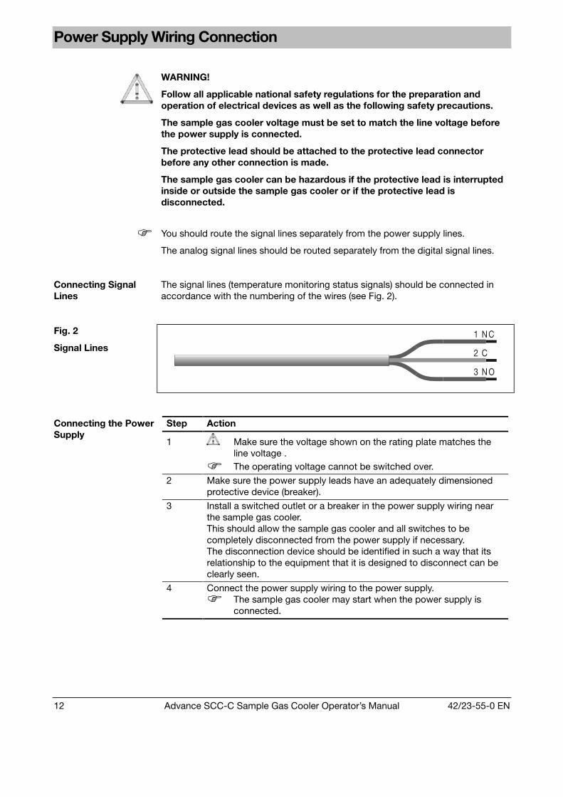
Connecting SignalLines
The signal lines (temperature monitoring status signals) should be connected inaccordance with the numbering of the wires (see Fig. 2).
Fig. 2
Signal Lines 2 C
3 N O
1 N C
Step Action
1 Make sure the voltage shown on the rating plate matches theline voltage .
The operating voltage cannot be switched over.
2 Make sure the power supply leads have an adequately dimensionedprotective device (breaker).
3 Install a switched outlet or a breaker in the power supply wiring nearthe sample gas cooler.This should allow the sample gas cooler and all switches to becompletely disconnected from the power supply if necessary.The disconnection device should be identified in such a way that itsrelationship to the equipment that it is designed to disconnect can beclearly seen.
Connecting the PowerSupply
4 Connect the power supply wiring to the power supply.
The sample gas cooler may start when the power supply isconnected.

42/23-55-0 EN Advance SCC-C Sample Gas Cooler Operator’s Manual 13
Power Supply Activation, Lead Time
WARNING!
Before activating the power supply check once again that the operatingvoltage setting matches the line voltage (see rating plate)
The sample gas flow should only be started after the lead time period.
Power SupplyActivation
Activate the power supply using the externally installed breaker or the switchedoutlet.
The peristaltic pumps start to run (counterclockwise).
Lead Time The lead time is approx. 15 minutes. This allows the sample gas outlet temperatureof +3 °C, which is set in the factory, to be reached.
Status Signal During the lead time the monitor will output the temperature exceeded statussignal.
Readiness At the end of the lead time period the sample gas cooler is ready for operation.
Sample Gas Supply The sample gas must not be switched on until the sample gas outlet temperaturelies within the limit values set in the factory, i.e. when it has fallen below +6 °C.
14 Advance SCC-C Sample Gas Cooler Operator’s Manual 42/23-55-0 EN
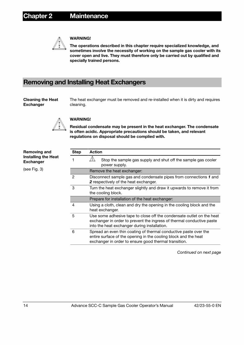
Chapter 2 Maintenance
WARNING!
The operations described in this chapter require specialized knowledge, andsometimes involve the necessity of working on the sample gas cooler with itscover open and live. They must therefore only be carried out by qualified andspecially trained persons.
Removing and Installing Heat Exchangers
Cleaning the HeatExchanger
The heat exchanger must be removed and re-installed when it is dirty and requirescleaning.
WARNING!
Residual condensate may be present in the heat exchanger. The condensateis often acidic. Appropriate precautions should be taken, and relevantregulations on disposal should be complied with.
Step Action
1 Stop the sample gas supply and shut off the sample gas coolerpower supply.
Remove the heat exchanger:
2 Disconnect sample gas and condensate pipes from connections 1 and2 respectively of the heat exchanger.
3 Turn the heat exchanger slightly and draw it upwards to remove it fromthe cooling block.
Prepare for installation of the heat exchanger:
4 Using a cloth, clean and dry the opening in the cooling block and theheat exchanger.
5 Use some adhesive tape to close off the condensate outlet on the heatexchanger in order to prevent the ingress of thermal conductive pasteinto the heat exchanger during installation.
Removing andInstalling the HeatExchanger
(see Fig. 3)
6 Spread an even thin coating of thermal conductive paste over theentire surface of the opening in the cooling block and the heatexchanger in order to ensure good thermal transition.
Continued on next page
42/23-55-0 EN Advance SCC-C Sample Gas Cooler Operator’s Manual 15
Removing and Installing Heat Exchangers, continued
Step Action
Install the heat exchanger:
7 Insert the heat exchanger in the opening in the cooling block and,turning it slightly, push it downwards right to the limit stop.
8 Remove the adhesive tape from the condensate outlet on the heatexchanger and remove any thermal conductive paste that has beensqueezed out.
9 Connect the sample gas and condensate pipes to connections 1 and2 respectively of the heat exchanger.
Note the following points when installing a glass heat exchanger:Before fitting the GL coupling nuts you should check that thePTFE/silicone compression fittings are not damaged. The com-pression fittings should be fitted with their PTFE surface facingthe glass. The GL coupling nuts should be hand-tightened.
10 Ensure that the temperature sensor 4 is inserted in the cooling blockall the way to the limit stop.
Start the sample gas cooler again:
11 Verify the integrity of the open gas path.
12 Switch power supply to sample gas cooler back on.
13 The sample gas flow should only be restarted after the lead timeperiod.
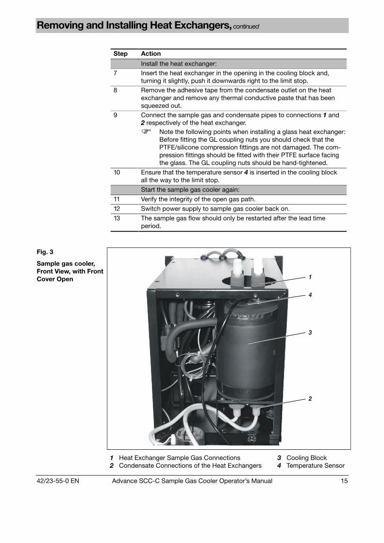
Fig. 3
Sample gas cooler,Front View, with FrontCover Open 1
4
3
2
1 Heat Exchanger Sample Gas Connections2 Condensate Connections of the Heat Exchangers
3 Cooling Block4 Temperature Sensor

16 Advance SCC-C Sample Gas Cooler Operator’s Manual 42/23-55-0 EN
Replacing Peristaltic Pump Hoses
When should theHoses be Replaced?
Depending on the operating cycle, the peristaltic pump hoses should be replacedat least every 5 months.
WARNING!
The hoses on the peristaltic pumps should never be lubricated.
The hoses can contain condensate residue. These materials can flow outwhen the hose connections are opened. Take appropriate measures whereneeded to collect residual condensates.
The condensate is often acidic. Appropriate precautions should be taken,and relevant regulations on disposal should be complied with.
Step Action
1 Stop the sample gas supply and shut off the sample gas coolerpower supply.
Remove the old hose:
2 Using the handles, press the moving belt 1 together and turn the S-clip 2 in a clockwise direction as far as its limit stop.
3 Remove the moving belt 1 from the pump head and pull the old hose 3by the hose connections 4 to release it from the moving belt's guides.
4 Press the pressure rollers 5 together and check the spring pressure; ifit is too weak, then the pressure springs and possibly rollers should bereplaced (see page 18).
Fit a new hose:
5 Insert a new hose 3 with hose connections in the guides on themoving belt 1.
6 Insert moving belt 1 with the new hose in the dovetail guide 6 in thepump head; using the handles, press the moving belt together while atthe same time turning the S-clip 2 counterclockwise until it engages.
Restart the sample gas cooler:
7 Check sample gas cooler seal integrity.
8 Switch on power supply to sample gas cooler.
Replacing PeristalticPump Hoses
(see Fig. 4)
9 The sample gas flow should only be restarted after the lead timeperiod.
Continued on next page
42/23-55-0 EN Advance SCC-C Sample Gas Cooler Operator’s Manual 17
Replacing Peristaltic Pump Hoses, continued
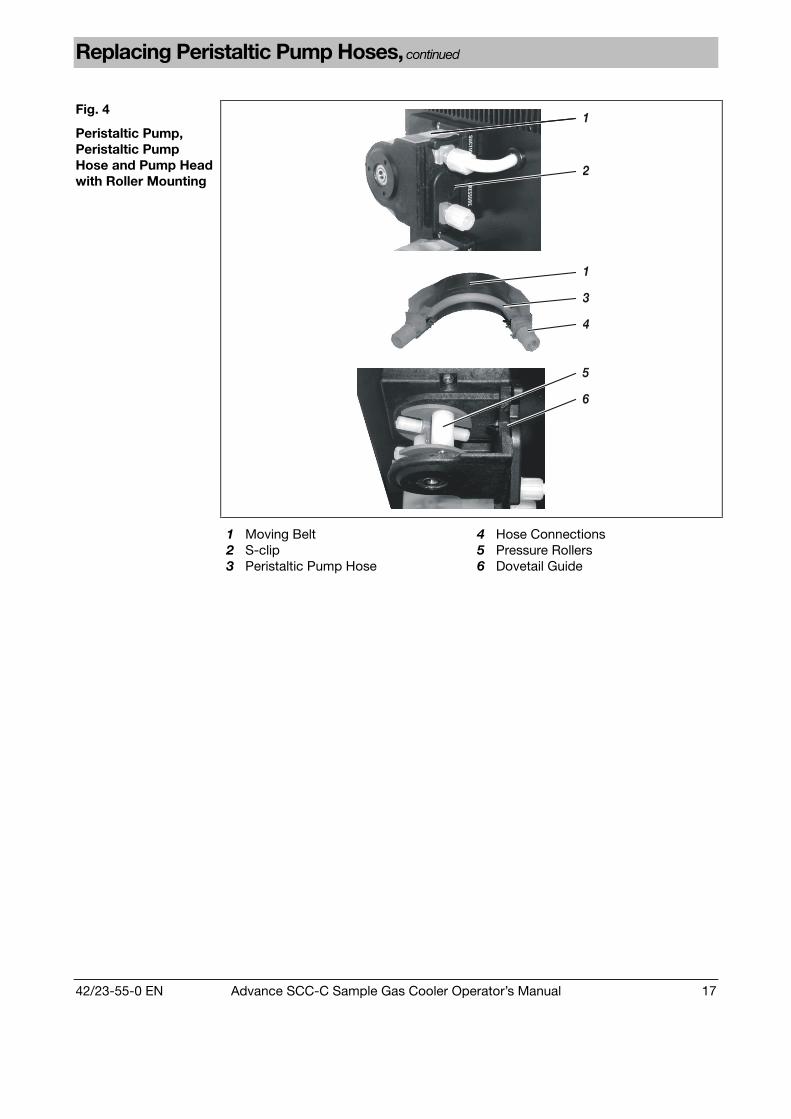
Fig. 4
Peristaltic Pump,Peristaltic PumpHose and Pump Headwith Roller Mounting
1
2
1
3
4
5
6
1 Moving Belt2 S-clip3 Peristaltic Pump Hose
4 Hose Connections5 Pressure Rollers6 Dovetail Guide

18 Advance SCC-C Sample Gas Cooler Operator’s Manual 42/23-55-0 EN
Replacing Peristaltic Pump Pressure Rollers and Springs
When do the PressureRollers and Springsneed to be Replaced?
The pressure rollers in the peristaltic pumps must be replaced when their surface isdamaged.
The pressure springs in the peristaltic pumps must be replaced when they arebroken.
Step Action
1 Stop the sample gas supply and shut off the sample gas coolerpower supply.
Remove the hose from the peristaltic pump:
2 Using the handles, press the moving belt 1 together and turn the S-clip 2 in a clockwise direction as far as its limit stop; then remove themoving belt and peristaltic pump hose from the pump head.
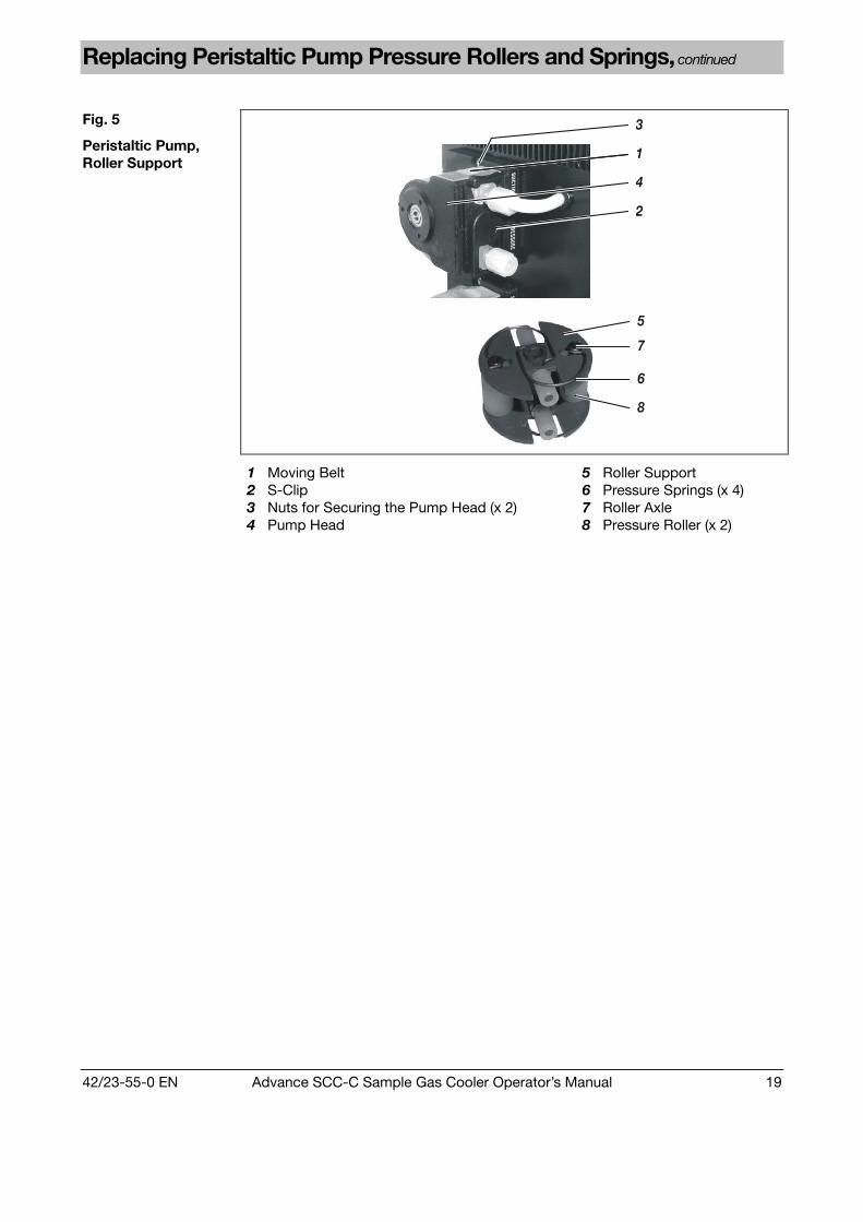
Dismantle the pump head:
3 Unscrew the two nuts 3 that secure the pump head (spanner size 5.5).
4 Pull the pump head 4 off the roller bearing axle, and remove the rollersupport 5 from the pump head.
Replace pressure rollers and springs:
5 Remove the pressure springs 6 from the hole in the roller support 5and from the retaining slot in the roller axle 7. Remove the roller axlefrom the roller support and pull the pressure roller 8 off the roller axle.
6 Push the new pressure roller 8 onto the roller axle 7 and secure withnew pressure springs 6 in the roller support 5.
Fit the pump head:
7 Insert the roller support 5 in the pump head 4, and push bothcomponents together onto the roller support axle. During this process,check to endure that the roller support axle and roller support fittogether properly.
8 Secure the pump head 4 with the two nuts 3.
It is expedient to open the front cover forwards: this enables thepump's baseplate with the fastening screws to be secured frominside.
Refit the peristaltic pump hose:
9 Insert moving belt 1 with the peristaltic pump hose in the pump head;using the handles, press the moving belt together while at the sametime turning the S-clip 2 counterclockwise until it engages.
Start the sample gas cooler again:
10 Verify the seal integrity of the sample gas cooler.
11 Switch power supply to sample gas cooler on.
Replacing PressureRollers and Springs
(see Fig. 5)
12 The sample gas flow should only be restarted after the lead timeperiod.
Continued on next page
42/23-55-0 EN Advance SCC-C Sample Gas Cooler Operator’s Manual 19
Replacing Peristaltic Pump Pressure Rollers and Springs, continued
Fig. 5
Peristaltic Pump,Roller Support
3
4
1
2
5
7
6
8
1 Moving Belt2 S-Clip3 Nuts for Securing the Pump Head (x 2)4 Pump Head
5 Roller Support6 Pressure Springs (x 4)7 Roller Axle8 Pressure Roller (x 2)

20 Advance SCC-C Sample Gas Cooler Operator’s Manual 42/23-55-0 EN
Clean Condenser Fins
When Should theCondenser Fins beCleaned?
Cooling performance is reduced by the accumulation of dust on the condenserfins.
For this reason the condenser fins should be inspected regularly and cleaned ifany dust deposits are visible.
Step Action
1 Stop the sample gas supply and shut off the sample gas coolerpower supply.
2 Undo the 4 fastening screws on the front cover and open it forwards(the front cover remains attached in the rebate of the base plate).
3 Undo the 8 fastening screws on the covering hood, release the cablelug of the protective leads from the quick terminal on the inside of thecovering hood, then lift the covering hood off.
4 Carefully blow compressed air onto the condenser fins 1.
5 Press the cable lug of the protective leads onto the quick terminal onthe inside of the covering hood, put the covering hood in place (takingcare not to trap any cables or hoses), and secure it in place with the 8screws.
6 Close front cover (taking care not to trap cables or hoses), and fastenit with the 4 screws.
7 Switch power supply to sample gas cooler on.
Cleaning theCondenser Fins
(see Fig. 6)
8 The sample gas flow should only be restarted after the lead timeperiod.
Fig. 6
Condenser
1
1 Condenser Fins
42/23-55-0 EN Advance SCC-C Sample Gas Cooler Operator’s Manual 21
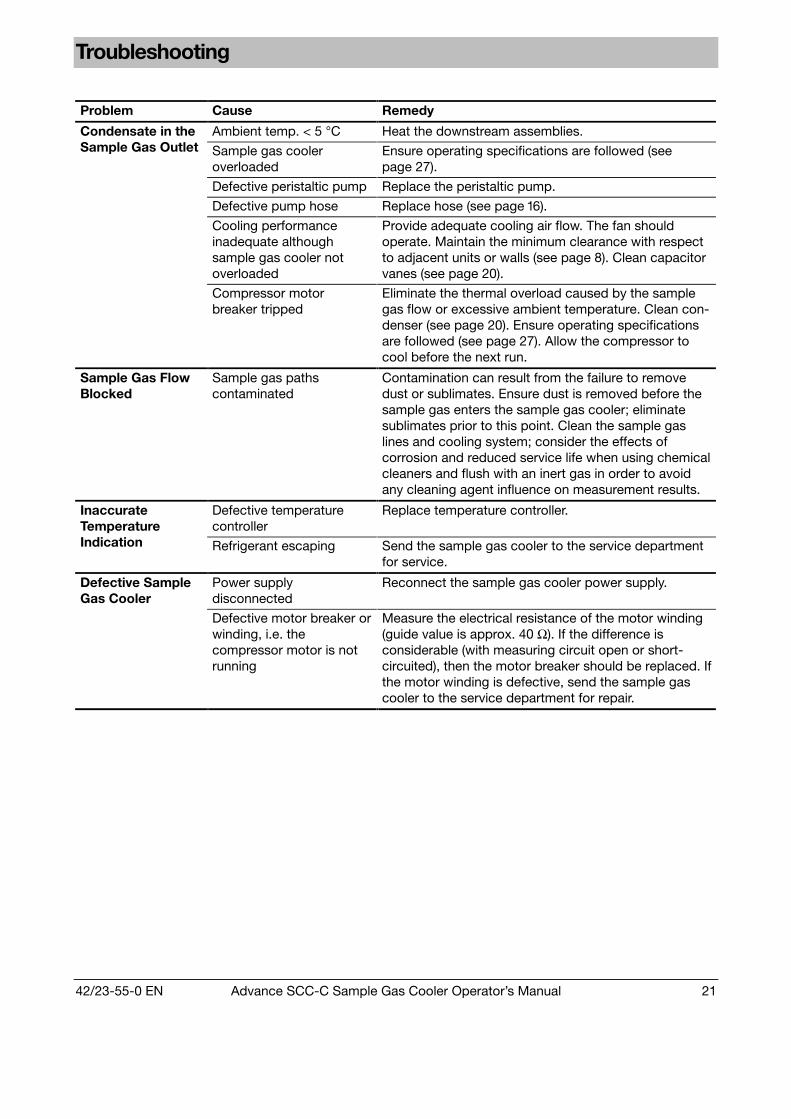
Troubleshooting
Problem Cause Remedy
Ambient temp. < 5 °C Heat the downstream assemblies.
Sample gas cooleroverloaded
Ensure operating specifications are followed (seepage 27).
Defective peristaltic pump Replace the peristaltic pump.
Defective pump hose Replace hose (see page 16).
Cooling performanceinadequate althoughsample gas cooler notoverloaded
Provide adequate cooling air flow. The fan shouldoperate. Maintain the minimum clearance with respectto adjacent units or walls (see page 8). Clean capacitorvanes (see page 20).
Condensate in theSample Gas Outlet
Compressor motorbreaker tripped
Eliminate the thermal overload caused by the samplegas flow or excessive ambient temperature. Clean con-denser (see page 20). Ensure operating specificationsare followed (see page 27). Allow the compressor tocool before the next run.
Sample Gas FlowBlocked
Sample gas pathscontaminated
Contamination can result from the failure to removedust or sublimates. Ensure dust is removed before thesample gas enters the sample gas cooler; eliminatesublimates prior to this point. Clean the sample gaslines and cooling system; consider the effects ofcorrosion and reduced service life when using chemicalcleaners and flush with an inert gas in order to avoidany cleaning agent influence on measurement results.
Defective temperaturecontroller
Replace temperature controller.InaccurateTemperatureIndication Refrigerant escaping Send the sample gas cooler to the service department
for service.
Power supplydisconnected
Reconnect the sample gas cooler power supply.Defective SampleGas Cooler
Defective motor breaker orwinding, i.e. thecompressor motor is notrunning
Measure the electrical resistance of the motor winding(guide value is approx. 40 Ω). If the difference isconsiderable (with measuring circuit open or short-circuited), then the motor breaker should be replaced. Ifthe motor winding is defective, send the sample gascooler to the service department for repair.

22 Advance SCC-C Sample Gas Cooler Operator’s Manual 42/23-55-0 EN
Chapter 3 Sample Gas Cooler Shutdown and Packing
Sample Gas Cooler Shutdown
Step Action
1 Disconnect the sample gas cooler power supply.
2 Shut off the sample gas supply to the sample gas cooler.
3 Loosen the sample gas and condensate lines from the sample gascooler ports.
The condensate that accumulates is often acidic. Neutralist thecondensate if necessary, and comply with relevant regulationson disposal.
4 Thoroughly purge the sample gas cooler gas paths with an inert gas.
5 Fully tighten the gas connections.
Sample Gas CoolerShutdown
6 Remove the electrical lines from the connectors.
If the sample gas cooler is returned to ABB Automation, e.g. for repair, pleaseindicate which gases have been supplied to the sample gas cooler.
This information is needed so that service personnel can take any safety pre-cautions required for harmful gases.
Make sure the sample gas cooler is free of residual moisture that can freeze if lowtemperatures are encountered during shipping and storage.
Ambient temperature for storage and transportation: –25...+60 °C
42/23-55-0 EN Advance SCC-C Sample Gas Cooler Operator’s Manual 23
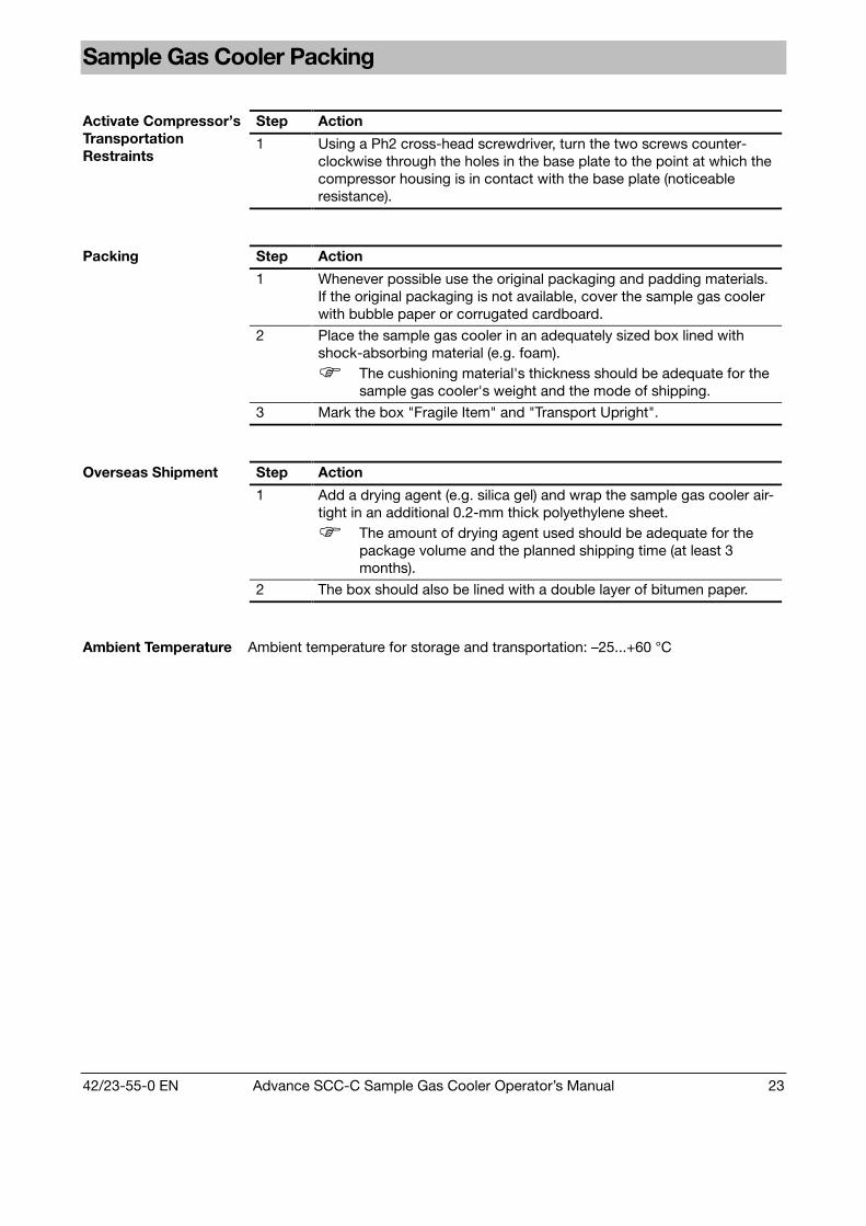
Sample Gas Cooler Packing
Step ActionActivate Compressor’sTransportationRestraints
1 Using a Ph2 cross-head screwdriver, turn the two screws counter-clockwise through the holes in the base plate to the point at which thecompressor housing is in contact with the base plate (noticeableresistance).
Step Action
1 Whenever possible use the original packaging and padding materials.If the original packaging is not available, cover the sample gas coolerwith bubble paper or corrugated cardboard.
2 Place the sample gas cooler in an adequately sized box lined withshock-absorbing material (e.g. foam).
The cushioning material's thickness should be adequate for thesample gas cooler's weight and the mode of shipping.
Packing
3 Mark the box "Fragile Item" and "Transport Upright".
Step Action
1 Add a drying agent (e.g. silica gel) and wrap the sample gas cooler air-tight in an additional 0.2-mm thick polyethylene sheet.
The amount of drying agent used should be adequate for thepackage volume and the planned shipping time (at least 3months).
Overseas Shipment
2 The box should also be lined with a double layer of bitumen paper.
Ambient Temperature Ambient temperature for storage and transportation: –25...+60 °C

24 Advance SCC-C Sample Gas Cooler Operator’s Manual 42/23-55-0 EN
Appendix
Advance SCC-C Sample Gas Cooler Applications and Functions
Sample Gas CoolerApplications
The Advance SCC-C sample gas cooler forms part of the sample gas conditioningsystem in an analysis system.
The moist sample gas is cooled in the sample gas cooler to such a degree that thetemperature does not fall below the dew point at any point further on in thesystem, and thus no condensate can penetrate the analyzer.
Sample Gas CoolerFunctions
The functions of the Advance SCC-C sample gas cooler are:• Cooling the sample gas,• Separating off the condensate and• Removing the condensate.
With some specific measuring tasks the dew point of the sample gas must be keptconstant in order to nullify the influence of the water vapor on the measurementresult. In these cases, turning on the test gas before the sample gas cooler has theeffect of keeping the water vapor percentage in calibration constant.
Use in conjunctionwith the AdvanceSCC-F Sample GasSupply Module
The Advance SCC-C sample gas cooler can be used in conjunction with theAdvance SCC-F sample gas supply module.
The functions of the Advance SCC-F sample gas supply module are:• Monitoring condensation at the sample gas coolers sample gas outlet,• Dosing reagent,• Sample gas feeding, and• Setting and monitoring the flow rate.
The functionality and operation of the Advance SCC-F sample gas supply moduleare described in the operating manual (document no. 42/23-51 EN).
Notes on ExplosionProtection
The Advance SCC-C sample gas cooler must not be used in hazardous areas.
In hazardous areas (zone 1) the CGEK 5-Ex sample gas cooler should be used.
The model of sample gas cooler featuring stainless-steel heat exchangers issuitable for use with combustible sample gases.

42/23-55-0 EN Advance SCC-C Sample Gas Cooler Operator’s Manual 25
Description
Principle The Advance SCC-C sample gas cooler contains 1 or 2 heat exchangers in whichthe sample gas is cooled down to around +3 °C.
Refrigerant Circuit
(see Fig. 7)
Depending on the operating conditions, the refrigerant compressor 1 compressesthe vaporous refrigerant from suction pressure of around 100 kPa (= 1.0 bar) to800–1700 kPa (= 8–17 bar).
In the downstream air-cooled refrigerant condenser 2 the vaporous refrigerant iscondensed by means of cooling. The liquid refrigerant flows through the refrigerantdrier 3 to the capillary pipe 4.
In the capillary tube 4 the pressure of the liquid refrigerant is reduced from itscondensation pressure 800–1700 kPa (= 8–17 bar) to a lower pressure (evaporationpressure) 100 kPa (= 1.0 bar), and the refrigerant passes into the evaporator 6.
In the heat exchanger 5, which is inset in a hole in the cooling block 7, energy isextracted from the sample gas; the sample gas is cooled, and the energy is fedinto the vaporous refrigerant at an evaporation pressure of 100 kPa (= 1.0 bar,approx. –10 °C). The vaporous refrigerant is sucked in once more by the refrigerantcompressor 1.
In order to keep the sample gas outlet temperature (dew point) constant, therefrigerant mass flow is regulated by the temperature-controlled valve 8 upstreamof the refrigerant compressor in accordance with the output required.
Fig. 7
Refrigerant Circuit1
2
3
4
56
7
8
°C9
1 Refrigerant Compressor2 Refrigerant Condenser3 Refrigerant Drier4 Capillary Tube5 Heat Exchanger6 Evaporator7 Cooling Block8 Valve9 Temperature Controller
Continued on next page
26 Advance SCC-C Sample Gas Cooler Operator’s Manual 42/23-55-0 EN
Description, continued
Condensate Removal
(see Fig. 7)
The condensate that accumulates comes out via the condensate nozzle on theheat exchanger 5.
The condensate is removed automatically by the peristaltic pump, which isincorporated as an optional extra.
Sample Gas OutletTemperatureMeasurement andDisplay
(see Fig. 7)
The measuring gas outlet temperature is measured using the Pt-100 temperaturesensor in the cooling block 7 of the sample gas cooler, and displayed in digitalform in °C on temperature controller 9. The sample gas outlet temperature is set inthe factory to +3 °C.
Sample Gas OutletTemperatureMonitoring
The temperature controller sends out a status signal if the temperature risesabove/falls below the respective limit values of +3 °C ± 3 °C as set up in thefactory. This signal is present at a floating change-over contact that is rated up to250 V AC/2 A.
Set Point Adjustment The set point for the sample gas outlet temperature can be set at the temperaturecontroller:
Press key P; the set point is displayed. Use arrow keys to adjust the set point.Press key P; the new set point is stored.
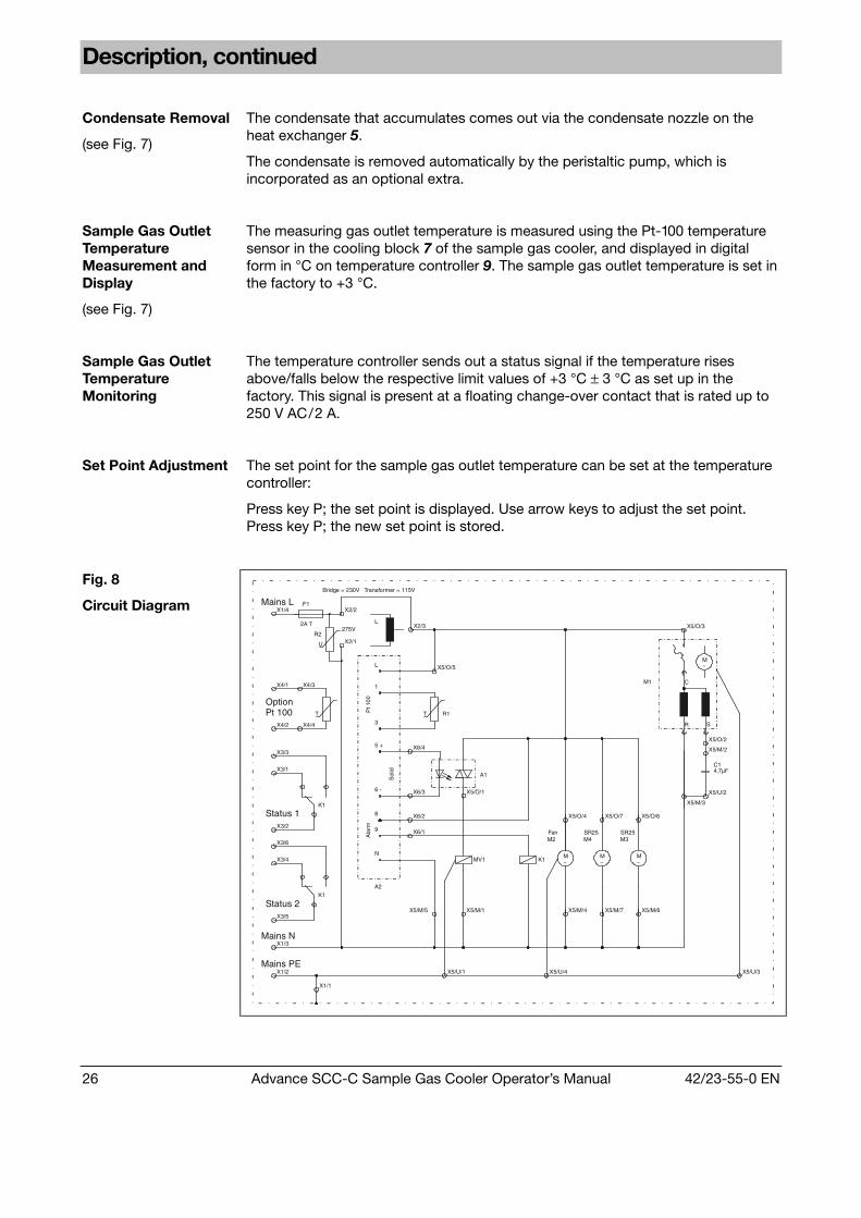
Fig. 8
Circuit Diagram
X5/O/2
X5/M/2
X5/U/2
4,7µFC1
X5/M/5 X5/M/1 X5/M/6X5/M/4 X5/M/7
X1/2
X1/3
X3/5
X1/1
X5/U/1 X5/U/4
Option
Pt 1
00
Status 2
Status 1
Pt 100X4/2
X3/1
X3/3
X3/2
X3/6
X3/4
K1A2
Ala
rm
N
9
8
X6/1
X6/2
K1
X4/4
Sol
id
6 - X6/3
5 +
3
X6/4
X4/1
X1/4F1
X2/1
X2/2
X4/3
2A T
1
L
LX2/3
X5/O/4
MV1 K1M~
M2
X5/O/1
A1
R1
X5/O/6
M~
SR25
M~
SR25
X5/O/7
M4 M3
X5/M/3
R S
X5/O/5
M1
M~
C
X5/O/3
X5/U/3
TT
U
275VR2
Mains PE
Mains N
Bridge = 230V Transformer = 115V
Mains L
Fan

42/23-55-0 EN Advance SCC-C Sample Gas Cooler Operator’s Manual 27
Operating Specifications
Sample Gas Pressure pabs
without withHeat ExchangerMaterial
peristaltic pump
Glass 50...200 kPa(0.5...2.0 bar)
50...150 kPa(0.5...1.5 bar)
PVDF 50...250 kPa(0.5...2.5 bar)
50...150 kPa(0.5...1.5 bar)
Sample Gas InletConditions
Sample Gas Pressure
Stainless Steel 0.05...1 MPa(0.5...10 bar)
Sample Gas Flow 1 x 250 l/h (WT250) or 1 x 125 l/h (WT125) or 2 x125 l/h, assuming sample gas pressure pabs =100 kPa (1 bar) and 25 °C
Sample Gas Inlet Temperature 140 °C
Sample Gas Inlet Dew Point 70 °C, max. 60 °C for WT250 where samplegas flow > 200 l/h
OperatingSpecifications
Sample Gas Outlet Temperature Factory-set to + 3 °C
Dew Point Stability ≤ ±0.3 °C per 10 °C temperature change,≤ ±0.3 °C per 10 l/h flow change
Overall Cooling Performance 40 W (at +10...+50 °C)
Lead Time Approx. 15 min
Heat Exchanger Pressure Loss Approx. 1 hPa (1 mbar)Approx. 4...8 hPa (4...8 mbar) for WT125
Heat ExchangerMaterial
WT125 WT250
Glass 40 ml 140 ml
PVDF 25 ml 100 ml
Heat Exchanger Total Volume
Stainless Steel 30 ml 100 ml
Gas Seal Integrity 5 x 10⁻⁶ hPa l/s
Ambient Conditions Ambient Temperature During operation: +10...+50 °CStorage and transport: –25...+60 °C
Relative Humidity ≤ 75 % year-round average, occasional lightcondensation permissible, ≤ 95 % on 30 daysper year

Subject to technical changesPrinted in the Fed. Rep. of Germany
42/23-55-0 EN 09.00