adsorptive removal of fluoride by micro-nanohierarchal web of activated carbon fibers
TRANSCRIPT

Adsorptive Removal of Fluoride by Micro-nanohierarchal Web of ActivatedCarbon Fibers
Amit Kumar Gupta, Dinesh Deva, Ashutosh Sharma, and Nishith Verma*
Department of Chemical Engineering and DST unit on Nanosciences,Indian Institute of Technology Kanpur, Kanpur, 208016, India
This study describes the development of aluminum impregnated hierarchal web of carbon fibers for the removalof dissolved fluoride in water. Micrometer-sized activated carbon fibers (ACF) were used as a substrate togrow carbon nanofibers (CNF) by chemical vapor deposition (CVD) using Ni as a catalyst. The hierarchalweb of micro-nanocarbon fibers (ACF/CNF) thus prepared was impregnated with aluminum (in its metallicstate) and then tested for the adsorption of fluoride ions over the concentration range of 1-50 ppm in waterunder both batch and flow conditions. The adsorbent web showed significant adsorption of fluoride ions. Inaddition, the total fluoride uptake was observed to be larger on aluminum impregnated ACF/CNF web thanon its parent material, the ACF alone impregnated with Al. Various analytical techniques including the scanningelectron microscopy (SEM), Raman spectroscopy, and the elemental analyzer were employed to characterizethe Al-impregnated ACF/CNF. The SEM images showed a complex 3D network of nanofibers uniformlydeposited with Al. This study is a step in developing a general platform suitable for producing potable waterthat also specifically addresses the problem of fluoride removal.
1. Introduction
According to World Health Organization norms, the upperlimit of fluoride concentration in drinking water is 1.5 mg/l.1
Excessive presence of fluoride (F) in potable water continuesto be a serious public health concern in many parts of the world,including India. Adsorption has shown considerable potentialin defluoridation of wastewater. The viability of such techniqueis greatly dependent on the development of suitable adsorptivematerials. In this respect, literature is replete with studies ondefluoridation, albeit using mostly alumina and oxides of a fewmetals as adsorbents.2-10 In most of these studies, performanceof the adsorbents has been evaluated under batch conditions,with temperature, pH, and dose of adsorbents being the primaryvariables.2-7 Few column studies have also been carried outwith a view to determining breakthrough curves and throughputvolume during dynamic (flow) conditions in packed beds.8-10
Traditional adsorbent like granular activated carbons (GAC)has also been tested for defluoridation, although without muchsuccess.11,12 The application of modified GAC in removal ofdissolved solutes has drawn interest.13-17 Although the modifiedGAC showed considerable potential in removing organicpollutants such as phenolic compounds, and to some extent,arsenic and manganese in wastewater, only partial success hasbeen reported on defluoridation. In one such study, equilibriumand kinetic studies were carried out on fluoride adsorption fromwater by zirconium ion impregnated coconut-fiber-derivedcarbon (ZICFC).18 In another study on defluoridation usingaluminum (Al)-impregnated activated carbon, the adsorption offluoride was shown to be strongly dependent on pH of thesolution and as a consequence the method required pre- andpost-treatment of the aqueous solution.19
On the basis of literature survey, it is fair to say that despiteseveral studies carried out on the adsorptive removal of fluorideions, the maximum removal efficiency reported is between60-90%. Removal in excess of 90% has also been reported,however, in acidic medium (pH < 4), thus requiring post-
treatment for preparing potable water at suitable pH. In additionto these limitations, there are several operational difficulties suchas plugging, fouling, and excessive pressure-drop, encounteredduring defluoridation using packed beds of granular adsorbentparticles, leading to periodic disruption of operation.
In this study, we have described the development of a micro-nanohierarchal web (MiNaHiWe) consisting of activated carbonfibers (ACF) and carbon nanofibers (CNF), impregnated withAl for the removal of fluoride ions over the concentration rangeof 1-50 ppm in wastewater. We chose impregnation byaluminum for this study because of the known strong affinityand selectivity toward fluoride ions of the adsorbents such asactivated alumina, zeolites, calcium aluminum silicate, and clay,all of which contain aluminum. The preparation steps primarilyinclude impregnation of the fibers with the aqueous solution ofaluminum nitrate, calcinations at high temperature to convertnitrate to oxide, and, subsequently, the reduction of oxide ofaluminum to its metallic state in a hydrogen atmosphere. Inthis work, we have focused on impregnation of the carbon webwith Al for fluoride removal. However, preparation of the webwith other appropriate methods of activation and impregnationhas the potential to develop MiNaHiWe into a multifunctionalplatform for catalytic and adsorptive purification of other gasand liquid mixtures.
The advantages of using the hierarchal mixture of micro- andnanofibers are as follows: (1) The active surface area is increaseddue to creation of nanopores. (2) As shown in the manuscript,metal impregnated web (Al-CNF) performs far superior to ACFalone or ACF impregnated with metal or CNF alone, and thusa multiscale structure is found to be the best. (3) CNF has to begrown on a support like metal oxides and has to be subsequentlyremoved and/or transferred to another porous substrate for use.The synthesis of hierarchical structure obviates the need for thesemultiple steps and directly provides a robust platform foradsorption applications such as making a filter. In our recentstudy we have successfully demonstrated the application of CNFgrown this way in removing NO by adsorption and catalyticreaction.20 Inspired by our study on the application of MiNa-HiWe of carbon in the gaseous phase reaction, we have carried
* To whom correspondence should be addressed. E-mail: [email protected]. Tel.: +91-512-2597704. Fax: +91-512-2590104.
Ind. Eng. Chem. Res. 2009, 48, 9697–9707 9697
10.1021/ie801688k CCC: $40.75 2009 American Chemical SocietyPublished on Web 04/28/2009

out the present study on the Al-impregnated CNF for theremoval of fluorides in the aqueous phase. We have alsocharacterized the adsorbents for their surface characteristicsusing the several state-of-the-art analytical techniques includingscanning electron microscopy (SEM), energy dispersive X-ray(EDX), and Raman spectroscopy.
The method described in this study for the synthesis ofAl-CNF is new and environmentally benign, without requiringany pre- or post-treatments. The design of the perforated tubularreactor used in this study for carrying out adsorption tests isalso new. The liquid-solid contact arrangement made in thetubular reactor not only ensures uniform flow of the solutionthrough the wrapped cloth, but also permits conduct of the testsunder both batch and continuous flow conditions. In addition,the possibility of channeling or nonwetting of the adsorbentsurfaces is minimal. We have used a similar type of arrangement(perforated tubular contactor) in our earlier studies on ACF forthe gas-phase reactions.21-24 The experimental results in thepresent study demonstrate larger uptake of the solute (fluorideions) and throughput volume of the fluoride laden water by theprepared adsorbents (Al-CNF) in comparison to those byalumina, GAC, modified GAC, and other commercial adsor-bents, as reported in open literature. For comparison, Al-ACFwas also prepared in this study. This study assumes significancefrom the perspective of developing suitable defluoridationtechnique for wastewater and the application of nanotechnologyin the context of environmental pollution control.
2. Experimental Details
2.1. Preparation of Al-ACF Samples. The starting sub-strate used was the phenolic-based activated carbon fibers(Kynol Inc., Japan). The specific surface area of the preparedACF samples was calculated by N2 adsorption. The adsorptionisotherms were measured by N2 adsorption at 77 K using BETsurface area analyzer (model: Autosorb 1C, Quantachrome, FL).The analysis showed typically 1200-1400 m2/g of BET area.To begin with, the as-received samples of fibers were leachedby dipping them in DI water for around 6 h to remove anyundesirable ions from the surface and to render the subsequentsteps (impregnation, etc.) effective. The ion analysis of the spentwater showed chlorides, nitrates, and phosphate ions in the rangeof 1-5 ppm.
All chemicals used in the study were of high purity grade(Merk). The aluminum nitrate solution of 0.4 M concentrationwas used for impregnation. The salt concentration in excess of0.4 M resulted in precipitation of aluminum nitrate crystals overACF surface. The X-ray diffraction (XRD) test confirmed theexistence of crystals at 0.5 M or larger concentration. Thesamples impregnated with relatively larger nitrate concentrationsolution also showed insignificant adsorption of fluoride ionsdue to the blocking of pores of ACF by the precipitated crystals.In our earlier studies on the application of metal impregnatedACF in the adsorptive or catalytic removal of the gaseousspecies, we observed the similar adverse effect because of theprecipitation of the crystals at relatively larger concentrationlevels.21
Figure 1 is the schematic of the experimental setup used inthe study. Impregnation was carried out in an inconel madetubular reactor (i.d. ) 2.5 cm, o.d. ) 2.8 cm, L ) 6 cm)mounted inside an inconel shell (i.d. ) 4.0 cm, L ) 10 cm)with provision made for the water inlet and outlet. One end ofthe tube was closed. The outer surface of the tube was perforatedwith holes of diameter 0.1 mm at center-to-center distances of0.4 cm. ACF was wrapped over the perforated section of the
tube. With the aid of a peristaltic pump, the solution in a glasscontainer was continuously recirculated to the inlet of the tube,as shown in the schematic. Valve A was kept closed and Bwas kept open. It was observed that this method (impregnationunder flow condition) resulted in uniform dispersion of thesolutes in ACF as compared to other traditional methods likeimpregnation by continuously stirring ACF in salt solution orleaving ACF in the solution under batch condition withoutstirring. Additionally, the total time of impregnation was alsoconsiderably reduced (less than 6 h) in the case of continuousrecycling, as against 12-14 h taken under the stagnantcondition.
After impregnation, the tube-shell assembly was taken outwithout removing the wrapped ACF for further processing ofthe sample. First, the sample was dried for 3 h at 50 °C in asmall nitrogen flow to remove surface moisture. Drying andthe subsequent treatment were carried out in a vertical quartztube as schematically described in Figure 2. After drying, thesample was calcined in an oxygen flow at 300 °C for 2 h toconvert nitrate into oxide. Following calcination, the samplewas cooled to room temperature. To convert oxide into thecorresponding metallic state, reduction was carried out in thehydrogen flow of 0.16 splm and at 350 °C for 1 h. The reducedsample (Al-ACF) is ready for testing. The stock solution of100 mg/L fluoride was prepared by dissolving 221 mg ofanhydrous NaF in 1 L of distilled water for the subsequentexperiments.
2.2. Preparation of CNF and Al-CNF. The method ofgrowing CNF on ACF is described in our recent study and isnot reproduced here for the sake of brevity.20 In brief, ACFwas impregnated with the nickel nitrate hexahydrate solutionprepared in acetone, subsequently calcined at high temperatureand then reduced in a hydrogen atmosphere to convert the saltof Ni to its metallic state, the procedure of impregnation to
Figure 1. Schematic of the experimental setup for the preparation ofimpregnated activated carbon fiber and adsorption studies.
Figure 2. Schematic of experimental setup for drying/calcination/reductionof impregnated ACF.
9698 Ind. Eng. Chem. Res., Vol. 48, No. 21, 2009
reduction being identically the same as that followed inpreparing Al-ACF. CNF was subsequently grown on theprepared Ni-ACF in a CVD reactor at the reaction temperatureof 1023 K using benzene as a source of carbon. The hierarchalweb of ACF/CNF was then sonicated in dilute nitric acid toremove Ni from the tips or the surfaces of the grown CNF.Some samples of CNF without sonication were also preparedfor the comparative study. The prepared CNF was reimpregnatedwith Al(NO3)3 and subsequently processed to prepare Al-CNF.
2.3. Batch (Equilibrium) and Column (Flow) Studies. Afixed amount of the adsorbent (either ACF, Al-ACF, CNF, orAl-CNF) was put in 150 mL of aqueous solution of sodiumfluoride. The temperature of the solution was maintainedconstant. The experimental arrangement was the same as in theprevious case (Figure 1). The solution was periodically collectedand analyzed for fluoride ions using METROHM ion chroma-tography (model: IC 861). The measurement was carried outuntil the concentration of the solution remained unchanged andadsorption equilibrium concentration was attained. The proce-dure was repeated for varying amounts of the sample, temper-ature, and initial fluoride concentration. It may be pointed outthat similar to the previous case (impregnation of ACF withAl), total time to reach equilibrium was considerably reducedby recirculation of the solution. However, the total amounts offluorides adsorbed, that is, equilibrium concentrations, werefound to be approximately the same (within a difference of(5%) in two cases (with and without flow).
The arrangement for the experimental setup used for conduct-ing dynamic (breakthrough) tests was the same as that forimpregnation and equilibrium studies, except that the valve Awas kept open and B was kept closed. The solution wascontinuously delivered at a constant flow rate with the aid of aperistaltic pump to the perforated tubular reactor wrapped withthe Al-ACF/Al-CNF sample. To begin with, DI water waspumped through the tube. At t ) 0+, a step change in the inletconcentration was induced by switching the inlet to the tube tothe fluoride solution of a certain concentration. Samples for theconcentration measurement were collected at the exit of the tubeover a certain time interval, until the exit concentration levelreached approximately that at the inlet to the tube. The entireprocedure was repeated for different amounts of the samples,pump speed (solution flow rate), and inlet fluoride concentration.
3. Batch (Equilibrium) Study
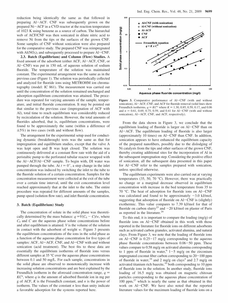
The concentration of solute in the solid phase was theoreti-cally determined by the mass balance: q )V(C0 - C)/w, whereC0 and C are the aqueous phase solute concentrations beforeand after equilibrium is attained. V is the volume of the solutionin contact with the adsorbent of weight w. Figure 3 presentsthe equilibrium concentrations of the ions in the solid phase asa function of the aqueous phase concentration for five types ofsamples: ACF, Al-ACF, CNF, and Al-CNF with and withoutsonication (acid treatment). The best fits to these data areessentially the equilibrium isotherms of fluoride ions versusdifferent samples at 35 °C over the aqueous phase concentrationsbetween 0.1 and 50 mg/L. For each sample, concentrations inthe solid phase are observed to monotonically increase withincreasing solution concentrations and are best explained by theFreundlich isotherm in the aforesaid concentration range, q )KCn, where q is the amount of adsorbed fluoride ion in mg perg of ACF, K is the Freundlich constant, and n is the power ofisotherm. The values of the constant n less than unity indicatea favorable adsorption for the systems reported here.
From the data shown in Figure 3, we conclude that theequilibrium loading of fluoride is larger on Al-CNF than onAl-ACF. The equilibrium loading of fluoride is also larger(approximately 10 times) on Al-CNF than CNF. In addition,sonication appears to have enhanced the equilibrium capacityof the prepared nanofibers, possibly due to the dislodging ofNi catalysts from the tips and other surfaces of the grown CNF,thereby creating additional sites for the incorporation of Al inthe subsequent impregnation step. Considering the positive effectof sonication, all the subsequent data presented in this paperfor Al-CNF refer to the samples prepared with sonication,unless specified otherwise.
The equilibrium experiments were also carried out at varyingtemperatures (35, 50, 70 °C). However, there was practicallyno change or a marginal decrease observed in equilibriumconcentration with increase in the bed temperature from 35 to70 °C. The heat of adsorption for fluoride ions on Al-CNFwas calculated and found to be approximately -3.0 kJ/mol,suggesting that adsorption of fluoride on Al-CNF is (slightly)exothermic. This value compares to 7.39 kJ/mol for that offluoride on carbon slurry25 and -20 kJ/mol on plaster of Parisas reported in the literature.26
To this end, it is important to compare the loading (mg/g) offluoride ions on Al-CNF obtained in this work with thosereported in the literature for fluoride ions on different adsorbentssuch as activated carbon granules, activated alumina, and naturalclays. From Figure 3, we note that the loading of fluoride ionson Al-CNF is 0.25-17 mg/g corresponding to the aqueousphase fluoride concentrations between 0.06-50 ppm. Thesevalues compare to 0.58 mg/g on activated alumina correspondingto 1 ppm of fluoride in water,6 1-5 mg/g on the zirconiumimpregnated coconut fiber carbon corresponding to 20-100 ppmof fluoride in water,18 and 2 mg/g on clays4 and 2.7 mg/g onactivated titanium rich bauxite,10 both corresponding to 10 ppmof fluoride ions in the solution. In another study, fluoride ionsloading of 16.5 mg/g was obtained on magnetic chitosanparticles corresponding to the aqueous phase concentration of100 ppm,27 which is nearly the same as that obtained in thiswork on Al-CNF. We have also noted that the reportedliterature values for the maximum loading of fluoride ions on a
Figure 3. Comparative performance of Al-CNF (with and withoutsonication), Al-ACF, CNF, and ACF for fluoride removal (solid lines showFreundlich isotherms, q ) KCn; where K ) 1.30, 0.85, 0.59, 0.17, and 0.06and n ) 0.61, 0.69, 0.75, 0.59, and 0.41 for Al-CNF (with and withoutsonication), Al-ACF, CNF, and ACF, respectively).
Ind. Eng. Chem. Res., Vol. 48, No. 21, 2009 9699

few inorganic sorbents is ∼1 mg/g or less corresponding to theaqueous phase concentration of 1 mg/L or less. From the datapresented in this section of the paper, we conclude that surfaceloading (equilibrium concentration) of fluoride ions on Al-CNFin this study is larger than those reported in literature, either on
carbon or alumina. We now turn our attention to the study onthe adsorption of fluoride ions by Al-CNF under dynamicconditions.
4. Breakthrough Characteristics
In the typical experiments performed to study breakthroughcharacteristics using the perforated tubular reactor wrapped withfresh (unsaturated) carbon fibers, the aqueous solution of fluorideat a predetermined concentration was fed at a constant flow rateto the reactor. One can make a reasonably good estimate of theeffective pore-diffusivity by fitting the experimental data withthe theoretical breakthrough curve. Such technique is commonlyused in estimating pore-diffusivity for the porous solids whosepore-size distribution may not be accurately determinedexperimentally.
From the many breakthrough data collected in this work, wepresent here only representative results. Figure 4 describes soluteconcentrations, Cexit measured at the exit of the packed columnof Al-CNF. The data are presented relative to the inletconcentration, Cin. As observed the exit concentration graduallyincreases, initially at a slow rate, until the outlet concentrationasymptotically reaches the inlet concentration. At this time, thepacked bed is saturated with fluoride ions and lacks capacityfor further adsorption. As also observed, breakthrough occursearlier for the relatively larger inlet concentration. It is alsopointed out that breakage of nanofibers and release of nanometalparticles were not observed during the experiment.
As regards the importance of interparticle mass transfercoefficient, we have earlier pointed out that the diameter ofcarbon fibers is small (ca. 1-10 µm). As a result, the fluid to
Figure 4. Breakthrough data for varying inlet fluoride concentration(WAl-CNF ) 3 g, Q ) 0.01 lpm, T ) 303 K).
Figure 5. SEM images of ACF (a) as-received, (b and c) post Al-reduction, and (d) EDX spectra of Al-ACF.
9700 Ind. Eng. Chem. Res., Vol. 48, No. 21, 2009
particle film mass transfer coefficient is significantly large inthe packed bed of fibers even at small liquid flow-rate.Theoretical calculations indeed showed a typically large valueof the liquid film mass transfer coefficient (of the order of 0.005m/s) under moderate or small particle Reynolds numbers in thepacked bed of Al-CNF. This is in contrast to the case ofadsorption in packed beds of larger particles, such as aluminapellets or charcoal beads. In these cases, the mass transfercoefficient may be small at small liquid flow-rates, since thesize of pellets or beads range from a few mm to cm. As a result,the mass transfer rate may be slow because it is controlled byinterparticle diffusion.
Figure 4 also describes theoretical curves obtained corre-sponding to the experimental conditions. The theoretical analysisis essentially based on three governing conservation equations:(a) species balance of the adsorbing component in the packedbed, (b) species balance of the component inside the pores ofthe fiber, and (c) surface adsorption and desorption rate withinthe pores. The analysis takes into account both inter- andintraphase diffusion resistances. In the present analysis, thegoverning equations (see appendix) are cast in the similar wayas in our previous studies on the application of ACF in controlof contaminants in gaseous phase.21-24 In the present case, thenumerical value of pore-diffusivities for fluoride ions wasadjusted at 5.5 × 10⁻¹⁰ m2/s to fit the data. One can calculatemolecular diffusivity of these ions in dilute solution byNearst-Haskell equation.28 On comparison it may be shownthat pore diffusivity of fluoride ions in the pores of carbon fibersis 1 order of magnitude smaller than molecular diffusivity (∼1.0× 10⁻⁹ m2/s). From the perspective of mass transfer rate, it isimportant to note that the characteristic time of intraparticle
diffusion in a pellet or fiber of diameter, df is proportional tothe square of the particle or fiber size, that is, df
2/Dpore, whereDpore is the effective pore diffusivity. Since CNF has small fibersize, characteristics time of pore-diffusion in fibers is muchsmaller than that in a pellet or bead. Thus, in the packed bedsof the former, separation is seldom controlled by intraparticlediffusion.
5. Surface Characterization
5.1. SEM/EDX Analysis. The morphology of Al-ACF andAl-CNF with and without sonication was examined by SEMand EDX analysis using the Supra 40 VP Field Emission SEMprocured from Zeiss. All images were captured with inlensdetector at accelerating voltage of 10 kV and filament current2.37 A at a working distance of 2-4 mm. The SEM imagesand EDX spectra of prepared samples were taken at a numberof locations on the samples. A representative image and thecorresponding EDX spectra of samples at different stages ofthe preparation are presented in Figures 5-8.
As observed from the SEM image of the as-received ACF,shown in Figure 5a, the surface of the carbon fibers is smooth,with the diameter in a narrow range of 10-20 µm. Onimpregnation with the salts of Al followed by reduction, thesurface of the fiber was uniformly dispersed with fine Alparticles, as observed in the SEM images taken at differentmagnifications (see Figures 5b and 5c). Agglomeration ofAl particles at a few locations may also be observed. Thecorresponding EDX spectra also confirmed the uniformdispersion of Al metal ions over the concentration range
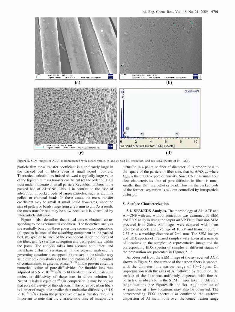
Figure 6. SEM images of ACF (a) impregnated with nickel nitrate, (b and c) post Ni- reduction, and (d) EDX spectra of Ni-ACF.
Ind. Eng. Chem. Res., Vol. 48, No. 21, 2009 9701
between 1.5 and 2.5% (wt/wt). One of such spectra is shownin Figure 5d.
The SEM image in Figure 6a shows the homogeneousdispersion of nickel nitrate on the surface of ACF followingthe impregnation and before the calcinations step. Figure 6panels b and c describe the SEM images of the ACF surface atdifferent magnifications after the reduction step. Fine nanosizedparticles may be observed to be uniformly dispersed on thesurface of the fiber. No sign of any deformation and loss ofintegrity or strength were found in the samples. The dispersedparticles on the surface of ACF were confirmed as nickelparticles using EDX spectra (see Figure 6d), with the concentra-tions obtained in the range, 3.0-3.5% (w/w).
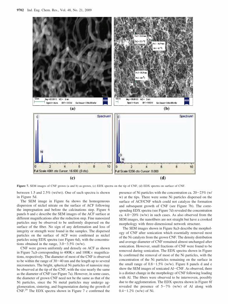
CNF were grown uniformly and densely on ACF as shownin Figure 7a,b corresponding to 400K× and 100K× magnifica-tions, respectively. The diameter of most of the CNF is observedto be within the range of 30-40 nm and the length up to severalmicrometers. The bright, spherical Ni particles of nanosize maybe observed at the tip of the CNF, with the size nearly the sameas the diameter of CNF (see Figure 7a). However, in some cases,the diameter of grown CNF need not be the same as that of theNi particles, since the Ni metal particles may undergo ag-glomeration, sintering, and fragmentation during the growth ofCNF.29 The EDX spectra shown in Figure 7 c confirmed the
presence of Ni particles with the concentration ca. 20-23% (w/w) at the tips. There were some Ni particles dispersed on thesurface of ACF/CNF which could not catalyze the formationand subsequent growth of CNF (see Figure 7b). The corre-sponding EDX spectra (see Figure 7d) revealed the concentrationca. 4.0-20% (w/w) in such cases. As also observed from theSEM images, the nanofibers are not straight but have a crookedmorphology with three-dimensional network structure.
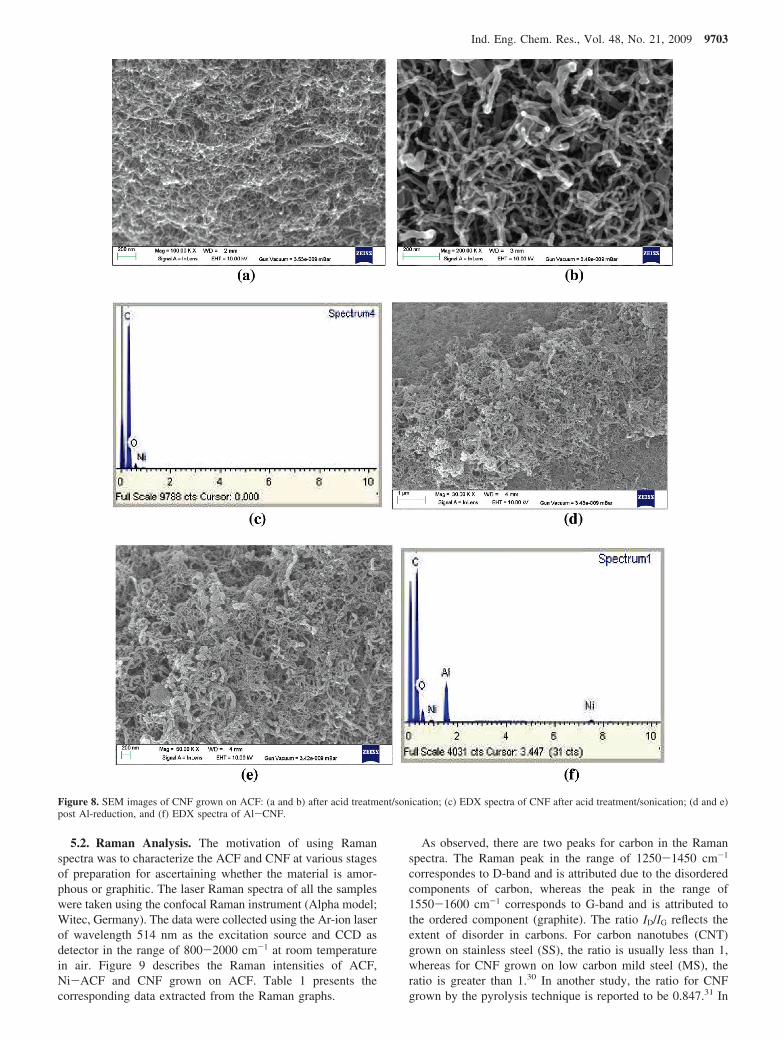
The SEM images shown in Figure 8a,b describe the morphol-ogy of CNF after sonication which essentially removed mostof the Ni catalysts from the grown CNF. The density distributionand average diameter of CNF remained almost unchanged aftersonication. However, small fractions of CNF were found to beremoved during sonication. The EDX spectra shown in Figure8c confirmed the removal of most of the Ni particles, with theconcentration of the Ni particles remaining on the surface inthe small range of 0.8-1.5% (w/w). Figure 8 panels d and eshow the SEM images of sonicated Al-CNF. As observed, thereis a distinct change in the morphology of CNF following loadingwith Al. The fibers were observed to be interwoven, possiblydue to the agglomeration. The EDX spectra shown in Figure 8frevealed the presence of 5-7% (w/w) of Al along with0.4-1.2% (w/w) of Ni.
Figure 7. SEM images of CNF grown (a and b) as-grown, (c) EDX spectra on the tip of CNF, (d) EDX spectra on surface of CNF.
9702 Ind. Eng. Chem. Res., Vol. 48, No. 21, 2009
5.2. Raman Analysis. The motivation of using Ramanspectra was to characterize the ACF and CNF at various stagesof preparation for ascertaining whether the material is amor-phous or graphitic. The laser Raman spectra of all the sampleswere taken using the confocal Raman instrument (Alpha model;Witec, Germany). The data were collected using the Ar-ion laserof wavelength 514 nm as the excitation source and CCD asdetector in the range of 800-2000 cm-1 at room temperaturein air. Figure 9 describes the Raman intensities of ACF,Ni-ACF and CNF grown on ACF. Table 1 presents thecorresponding data extracted from the Raman graphs.
As observed, there are two peaks for carbon in the Ramanspectra. The Raman peak in the range of 1250-1450 cm-1
correspondes to D-band and is attributed due to the disorderedcomponents of carbon, whereas the peak in the range of1550-1600 cm-1 corresponds to G-band and is attributed tothe ordered component (graphite). The ratio ID/IG reflects theextent of disorder in carbons. For carbon nanotubes (CNT)grown on stainless steel (SS), the ratio is usually less than 1,whereas for CNF grown on low carbon mild steel (MS), theratio is greater than 1.30 In another study, the ratio for CNFgrown by the pyrolysis technique is reported to be 0.847.31 In
Figure 8. SEM images of CNF grown on ACF: (a and b) after acid treatment/sonication; (c) EDX spectra of CNF after acid treatment/sonication; (d and e)post Al-reduction, and (f) EDX spectra of Al-CNF.
Ind. Eng. Chem. Res., Vol. 48, No. 21, 2009 9703

addition, the smaller is the ratio, the more highly ordered is thegraphitic structure. In the present analysis, the ID/IG ratio of ACFwas determined to be large, indicating the presence of disorderedgraphite components in the parent substrate material, that is,ACF. This disorder is observed to further increase during nickelimpregnation. As observed, CNF grown on ACF also retain theshort-range graphitic characteristics with an ID/IG ratio ) 2.89.
5.3. Elemental Analysis. Elemental analyzer was used toascertain change in the elemental compositions of ACF follow-ing impregnation with Ni for growing CNF. The compositionvariation, predominantly in carbon, was investigated by elemen-tal (CHN) analysis (Exeter Analytical Inc. made analyzer,model: CE 440). The data are presented in Table 2. As observed,the amount (percentage by weight) of carbon decreased in theNi-impregnated sample and that of nitrogen increased ascompared to ACF, due to the incorporation of nickel nitrate inACF. Following calcinations and reduction steps, the carboncontents expectedly increased, although marginally. The sig-
nificant increase in the carbon contents after CVD is obviousdue to the deposition of amorphous carbon on Ni-ACF.Subsequent decrease in the carbon contents after acid treatmentwas due to the removal of excess soot-carbon in the sonicationstep.
6. Total Uptake of Fluorides and Throughput Volume
The data discussed in this section pertain to the tests carriedout on Al-CNF packed in a tubular reactor, with the flow Qand inlet concentration of fluoride solution set at prescribedvalues (see Figure 1). Valve A was kept open and B was keptclosed. It is pointed out that breakthrough characteristics is atrue reflection of the performance of an adsorbent under dynamiccondition. In principle, steady-state conditions never exist duringadsorption, except at the final stage of the operation when theadsorbent is nearly saturated with adsorbate, denoting asymptoticattainment of equilibrium. At this instance, the aqueous phaseconcentration at the exit of the adsorber equals that at the inletto the adsorber. In such a process, two important parametersthat may be used to describe the relative effectiveness ofadsorbents are the throughput volume (total volume of feedsolution passed through the bed until the bed is saturated) andthe total uptake of the solute (fluoride in the present case) duringthat period. The former is calculated as Q∆t, where ∆t is thetime spent until saturation of the bed, whereas the latter isdetermined from the breakthrough curve (i.e., hatched areamarked in Figure 4 for the uppermost curve) by calculating theintegral along the curve between the two time limits, theincipience of adsorption test and the instance when the bed issaturated. Mathematically the uptake of the solute (mg) isdetermined as follows:
where T is the total time of adsorption until the bed is saturatedwith the solute in the influent stream.
Table 3 summarizes the numerical values of two parameters,throughput volume and total uptake of fluoride ions, experi-mentally obtained under various conditions of concentration,flow-rate, and the amount of Al-CNF. Here, only representativedata are presented for brevity. There are two salient observationsthat can be made.
One, the fluid-to-particle (film) mass transfer coefficient isnearly independent of the fluid or solution flow-rate suggestinginsignificant influence of the interparticle diffusion resistanceon the removal of solutes from the fluid phase, under theexperimental conditions used in the study. The numerical value(∼5 × 10⁻³ m/s) of km obtained in this study compares to 5.6× 10⁻⁵ m/s reported by Pant and Ghorai8 for the packed bed ofalumina particles (average size ) 2.5 mm), with the superficial
Figure 9. Raman spectrum of (a) ACF, (b) Ni-ACF, and (c) CNF grownon ACF.
Table 1. Laser Raman Spectra Parameters
peak shift (cm-1) area
no. sample D-band G-band D-band G-band ID/IG
1 ACF 1331 1591 626583 245667 2.552 Ni-ACF 1333 1596 24826 8833 2.813 CNF 1328 1591 117779 40635 2.89
Table 2. CHN Analysis of Carbon Samples at Various Stages ofPreparation
no. sample % C % H % N% residue
(mostly Ni and O)
1 ACF 94.91 1.24 0.85 7.182 Ni-impregnated 68.50 1.72 3.77 36.993 Ni-reduced 73.16 1.64 1.59 30.074 CNF (preacid treatment) 84.20 1.32 1.07 18.195 CNF (postacid treatment) 76.88 0.99 2.05 26.16
Table 3. Total Uptake of Fluoride during Adsorption on Al-CNFunder Flow (Continuous Condition (Fiber Diameter ) 4.6 ×10⁻⁷ m)
sampleno.
Cinlet
(mg/L)W(g)
Q(lpm)
VR × 103
(m/s)km × 103
(m/s)Q∆t(L)
uptake offluoride (mg)
1 5 3 0.01 0.05 5.0 4.1 10.42 15 3 0.01 0.05 6.0 3.0 21.13 30 3 0.01 0.05 7.5 2.4 27.74 5 3 0.03 0.15 14.5 4.3 11.45 5 2 0.03 0.15 11.6 3.5 7.76 5 1 0.03 0.15 9.7 1.8 3.77 15 2 0.03 0.15 11.6 3.1 14.58 15 2 0.02 0.10 7.6 3.0 14.49 15 2 0.01 0.05 7.5 3.0 14.5
uptake (mg) ) Q(CinT - ∫0
TCexitdt) (1)
9704 Ind. Eng. Chem. Res., Vol. 48, No. 21, 2009

velocity of the aqueous solution of fluoride ions at 0.003 m/s.Clearly, the small fiber size has caused significant improvementin the mass transfer coefficient.
Two, the effect of fluoride concentration in the influenthas larger effect on the uptake of the solute than on thethroughput volume. Comparing the data for these twoquantities in rows one and two in Table 3, total amount offluoride removed is approximately doubled with increase inthe inlet concentration from 5 to 15 ppm, whereas thethroughput volume decreased by approximately 25%. Theresults are consistent with the breakthrough profiles shownin Figure 4. Although total adsorption time increases by notmore than 25% with decrease in the influent concentration,total amount of solute removed varies significantly as thecurve tends to be more concave down at low concentrationthan at high concentration, resulting in relatively larger areaabove the breakthrough curve. Similar concentration effectsmay be observed from the data reported in rows one andthree of Table 3. With increase in the concentration from 5to 30 ppm, the uptake amount is approximately tripled,whereas the throughput volume is halved.
From the foregoing discussion, we conclude that thethroughput volume and solute uptake are two parameters thatmust be used in screening adsorbents and comparing therelative performance of adsorbents under varying experi-mental conditions. We also point out that in this regard, mostof the literature data on the removal of fluoride by adsorbentpertain to equilibrium conditions (under stirred condition ina batch reactor). The ions-loading in such condition may nottruly reflect the removal efficiency of an adsorbent. In factthe adsorptive performance of an adsorbent must be ascer-tained under dynamic conditions, taking into account theinfluence of various diffusion resistances and finite adsorptionand desorption rates. We close this section of the discussionby comparing our results to the limited published data onthe throughput volume and fluoride uptake in a packedcolumn of activated alumina beads.8,9 It is pointed out thatwe numerically determined the value of fluoride uptake fromthe breakthrough curves reported in the aforesaid studiesusing eq 1. Therefore, comparison may be made within theexperimental and numerical errors only.
As observed from Table 4, the throughput volume of thefluoride solution and uptake are 4.1 L and 10.4 mg correspond-ing to 3 g of Al-CNF used in this study, in comparison to 65L and 150 mg, respectively corresponding to 200 g of activatedalumina used by Pant and Ghorai.8 In another study the twoparameters are obtained to be 100 L and 267 mg on Mn oxidecoated alumina beads.9 In the latter study, the total amount ofthe adsorbent was 310 g, whereas the fluoride concentration inthe influent stream was 3.56 mg/L. Thus, the comparative datapresented in Table 4 is the obvious indicator of the superior
performance of Al-CNF in comparison to alumina whenadsorbents are used under dynamic (flow) conditions.
It is also important to note that (1) there are two types ofsites on the surface of the synthesized material, Al-CNF. Onthe vacant sites unoccupied by metals, the adsorption (phys-isorption) of fluoride is reversible, whereas on the sites occupiedby metal, the adsorption (chemisorption) of fluoride is irrevers-ible,32 (2) although it is sensible to compare the performanceof adsorbents using mg F/g adsorbent as metric, the comparisonmay also be made using mg F/m2 adsorbent.
In the present study, the BET surface area of parent material,ACF was determined to be 1200-1400 m2/g, which is signifi-cantly larger than that of the other commercial adsorbents suchas activated alumina (250 m2/g). The BET area of Al-CNF(due to N2 physisorption) was determined to be ∼850 m2/g,whereas the active metal sites area was measured by H2-reduction (due to chemisorption) and determined to be ∼0.26m2/g. At 5 mg/L of aqueous phase fluoride concentration, thesolid-phase fluoride concentration on Al-CNF was determinedto be ∼0.004 mg/m2, using the BET area as a basis, and ∼13.3mg/m2, using the metal active surface area as a basis. The formercompares favorably to ∼0.003 mg/m2 obtained for activatedalumina. We also determined the amount (∼7.8 mg Al/g ofAl-CNF) of aluminum impregnated on Al-CNF, using atomicabsorption spectroscopy (Varian AA-240). From this measure-ment, fluoride concentration on Al-CNF may also be calculatedas ∼0.44 mg F/mg Al at the aqueous phase fluoride concentra-tion of 5 mg/L.
7. Variation in the Solution pH
As shown below, pretreatment of the feedwater is not requiredwhile using the Al-CNF for treating the wastewater with pHbetween 5.0 and 8.0, which is also the typical pH range of thefluoride-rich potable water. However, under extreme conditionsof very high or very low pH, pretreatment may be required.We have not performed any experiments on the extreme pHranges to assess their effects (if any) on the web performanceand stability.
Figure 10 describes variation in pH values during fluorideremoval at different initial fluoride concentration and solutiontemperature. As observed, initial pH value is relatively lowerat larger fluoride concentration. The variation is in the rangebetween 6.0 and 6.75 corresponding to the initial fluorideconcentrations of 5 to 50 ppm. However, pH level thereafterremains approximately the same. Following the attainment ofequilibrium, approximately maximum 4% increase is observed.For example, pH level in the solution of 5 ppm of initial fluorideconcentration increases from 6.5 to approximately 6.75, whereasthat of 50 ppm-solution increases from 6 to 6.5 only. From theresults it may be inferred that the post-treatment (after defluo-
Table 4. Comparison of Reported Values of Throughput Volume of the Liquid and Total Uptake of Fluoride in a Tubular Packed BedAdsorber
no. parameters this study Pant and Ghorai8 Maliyekkal et al.9
1 adsorbent Al-CNF activated alumina Mg-coated alumina2 fiber or particle size (m) 1 × 10⁻⁷ 3.5 × 10⁻³ 0.8 × 10⁻³
3 column I.D. (m) 0.0198 0.0508 0.0284 solution flow rate (lpm) 0.01 0.03 0.02255 superficial liquid velocity (m/s) 5.0 × 10⁻³ 2.47 × 10⁻⁴ 6.09 × 10⁻⁴
6 km (m/s) 0.005 5.6 × 10⁻⁵ -7 amount of adsorbent (g) 3 200 310 (estimated)8 inlet fluoride concentration (mg/L) 5 5 3.569 throughput volume (L) 4.1 65 10010 uptake (mg) 10.4 150 26711 specific uptake (mg/g) 3.47 0.75 0.86
Ind. Eng. Chem. Res., Vol. 48, No. 21, 2009 9705
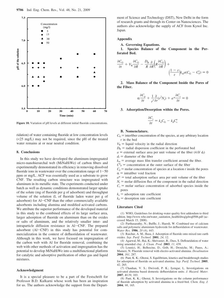
ridation) of water containing fluoride at low concentration levels(<25 mg/L) may not be required, since the pH of the treatedwater remains at or near neutral condition.
8. Conclusions
In this study we have developed the aluminum-impregnatedmicro-nanohierarchal web (MiNaHiWe) of carbon fibers andexperimentally demonstrated its efficiency in removing dissolvedfluoride ions in wastewater over the concentration range of 1-50ppm or mg/L. ACF was essentially used as a substrate to growCNF. The resulting carbon structure was impregnated withaluminum in its metallic state. The experiments conducted underbatch as well as dynamic conditions demonstrated larger uptakeof the solute (mg of fluoride per g of adsorbent) and throughputvolume of the solution (L of fluoride laden water per g ofadsorbent) for Al-CNF than the other commercially availableadsorbents including alumina and modified activated carbons.We attribute the superior performance of the developed materialin this study to the combined effects of its large surface area,larger adsorption of fluoride on aluminum than on the oxidesor salts of aluminum, and the relatively smaller inter- andintraparticle diffusion resistance in Al-CNF. The preparedadsorbent (Al-CNF) in this study has potential for com-mercialization in the context of defluoridation of wastewater.Although in this work, we have focused on impregnation ofthe carbon web with Al for fluoride removal, combining theweb with other methods of activation and impregnation has thepotential to develop MiNaHiWe into a multifunctional platformfor catalytic and adsorptive purification of other gas and liquidmixtures.
Acknowledgment
It is a special pleasure to be a part of the Festschrift forProfessor B.D. Kulkarni whose work has been an inspirationfor us. The authors acknowledge the support from the Depart-
ment of Science and Technology (DST), New Delhi in the formof research grants and through its Center on Nanosciences. Theauthors also acknowledge the supply of ACF from Kynol Inc.Japan.
Appendix
A. Governing Equations.1. Species Balance of the Component in the Per-
forated Bed.
2. Mass Balance of the Component Inside the Pores ofthe Fiber.
3. Adsorption/Desorption within the Pores.
B. Nomenclature.CG ) interfiber concentration of the species, at any arbitrary location
r in the bedVR ) liquid velocity in the radial directionDR ) radial dispersion coefficient in the perforated beda ) external surface area per unit volume of the fiber (4.0/ df)df ) diameter of the fiberkm ) average mass film transfer coefficient around the fiber.CS
F ) concentration at the outer surface of the fiberCp ) molar concentration of species at a location r inside the poresR ) intrafiber void fractiona* ) total adsorption surface area per unit volume of the fiberNr ) molar diffusion flux of the component in the radial directionCs ) molar surface concentration of adsorbed species inside the
poreska ) adsorption rate coefficientkd ) desorption rate coefficient
Literature Cited
(1) WHO, Guidelines for drinking-water quality first addendum to thirdedition. http://www.who.int/water_sanitation_health/dwq/gdwq0506.pdf (ac-cessed March 15, 2008).
(2) Parthasarathy, N.; Buffle, J.; Haerdi, W. Combined use of calciumsalts and polymeric aluminium hydroxide for defluoridation of wastewater.Water Res. 1986, 20 (4), 443.
(3) Raichur, A. M.; Basu, J. Adsorption of fluoride onto mixed rare earthoxides. Sep. Purif. Technol. 2001, 24, 12.
(4) Agarwal, M.; Rai, K.; Shrivastav, R.; Dass, S. Deflouridation of waterusing amended clay. J. Clean. Prod. 2003, 11, 439.
(5) Lounici, H.; Belhocine, D.; Grib, H.; Drouiche, M.; Pauss, A.;Mameri, N. Fluoride removal with electro-activated alumina. Desalination2004, 161, 287.
(6) Pant, K. K.; Ghorai, S. Equilibrium, kinetics and breakthrough studiesfor adsorption of fluoride on activated alumina. Sep. Purif. Technol. 2005,42, 265.
(7) Chauhan, V. S.; Dwivedi, P. K.; Iyengar, L. Investigations onactivated alumina based domestic defluoridation units. J. Hazard. Mater.2007, B139, 103.
(8) Pant, K. K.; Ghorai, S. Investigations on the column performanceof fluoride adsorption by activated alumina in a fixed-bed. Chem. Eng. J.2004, 98, 165.
Figure 10. Variation of pH levels at different initial fluoride concentrations.
∂CG
∂t+ VR
∂CG
∂R-
DR
R∂
∂R(R∂CG
∂R ) +
(1 - εε )kma(CG - CF
s ) ) 0
R∂Cp
∂t+ 1
r2
∂
∂r(r2Nr) + a*
∂Cs
∂t) 0
∂Cs
∂t) kaCG - kdCs
n
9706 Ind. Eng. Chem. Res., Vol. 48, No. 21, 2009

(9) Maliyekkal, S. M.; Sharma, A. K.; Philip, L. Manganese-oxide-coatedalumina: A promising sorbent for defluoridation of water. Water Res. 2006,40, 3497.
(10) Das, N.; Pattanaik, P.; Das, R. Defluoridation of drinking waterusing activated titanium rich bauxite. J. Colloid Interface Sci. 2005,292, 1.
(11) Gupta, V. K.; Ali, I.; Saini, V. K. Defluoridation of wastewatersusing waste carbon slurry. Water Res. 2007, 41, 3307.
(12) Fan, X.; Parker, D. J.; Smith, M. D. Adsorption kinetics of fluorideon low cost materials. Water Res. 2003, 37, 4929.
(13) Srivastava, V.; Mall, I. D.; Mishra, I. M. Adsorption of toxic metalions onto activated carbon study of sorption behaviour through characteriza-tion and kinetics. Chem. Eng. Process. 2008, 47, 1269.
(14) Cheng, W.; Dastgheib, S. A.; Karanfil, T. Adsorption of dissolvednatural organic matter by modified activated carbons. Water Res. 2005, 39,2281.
(15) Huang, H.; Lub, M.; Chen, J.; Lee, C. Catalytic decomposition ofhydrogen peroxide and 4-chlorophenol in the presence of modified activatedcarbons. Chemosphere 2003, 51, 935.
(16) Barkat, M.; Nibou, D.; Chegrouche, S.; Mellah, A. Kinetics andthermodynamics studies of chromium(VI) ions adsorption onto activatedcarbon from aqueous solutions. Chem. Eng. Process.: Process Intensif.2007.
(17) Mondal, P.; Majumder, C. B.; Mohanty, B. Effects of adsorbentdose, its particle size and initial arsenic concentration on the removalof arsenic, iron and manganese from simulated ground water by Fe3+
impregnated activated carbon. J. Hazard. Mater. 2008, 150, 695.(18) Sathish, R. S.; Raju, N. S. R.; Raju, G. S.; Rao, G. N.; Kumar,
K. A.; Janardhana, C. Equilibrium and kinetic studies for fluoride adsorptionfrom water on zirconium impregnated coconut shell carbon. Sep. Sci.Technol. 2007, 42 (4), 769.
(19) Ramos, R. L.; Ovalle-Turrubiarters, J.; Sanchez-Castillo, M. A.Adsorption of fluoride from aqueous solution on aluminum-impregnatedcarbon. Carbon 1999, 37, 609.
(20) Singhal, R.; Sharma, A.; Verma, N. Micro/nano hierarchal web ofactivated carbon fibers for catalytic gas adsorption and reaction. Ind. Eng.Chem. Res. 2008, 47 (10), 3700.
(21) Adapa, S.; Gaur, V.; Verma, N. Catalytic oxidation of NO byactivated carbon fiber (ACF). J. Chem. Eng. 2006, 116, 25.
(22) Gaur, V.; Sharma, A.; Verma, N. Synthesis and characterizationof activated carbon fiber for the control of BTX. Chem. Eng. Process. 2006,45, 1.
(23) Gaur, V.; Asthana, R.; Verma, N. Removal of SO2 by activatedcarbon fibers in presence of O2 and H2O. Carbon 2006, 44, 46.
(24) Gaur, V.; Sharma, A.; Verma, N. Catalytic oxidation of tolueneand m-xylene by activated carbon fiber impregnated with transition metals.Carbon 2005, 43, 3041.
(25) Gupta, V. K.; Ali, I.; Saini, V. K. Defluoridation of wastewatersusing waste carbon slurry. Water Res. 2007, 41, 3307.
(26) Gopal, V.; Elango, K. P. Equilibrium, kinetic and thermodynamicstudies of adsorption of fluoride onto plaster of Paris. J. Hazard. Mater.2007, 141 (1), 98.
(27) Ma, W.; Ya, F.; Han, M.; Wang, R. Characteristics of equilibrium,kinetics studies for adsorption of fluoride on magnetic-chitosan particle. J.Hazard. Mater. 2007, 141, 98.
(28) Cussler, E. L. Diffusion: Mass Transfer in Fluid System; CambridgeUniversity Press: New York, 1998.
(29) Chen, D.; Christensen, K. O.; Fernandez, E. O.; Yu, Z.; Tøtdal,B.; Latorre, N.; Monzon, A.; Holmen, A. Synthesis of carbon nanofibers:effects of Ni crystal size during methane decomposition. J. Catal. 2005,229, 82.
(30) Liu, Y.; Pan, C.; Wang, J. Raman spectra of carbon nanotubes andnanofibers prepared by ethanol flames. J. Mater. Sci. 2004, 39, 1091.
(31) Terrones, H.; Hayashi, T.; Munoz-Navia, M.; Terrone, M.; Kim,Y. A.; Grobert, N.; Kamalakaran, R.; Dorantes-Davila, J.; Escudero, R.;Dresselhaus, M. S.; Endo, M. Graphitic cones in palladium catalysed carbonnanofibers. Chem. Phys. Lett. 2001, 343, 241.
(32) Hubbard, A. T. Encyclopedia of Surface and Colloid Science; CRCPress: Boca Raton, FL, 2002; Vol. 3.
ReceiVed for reView November 5, 2008ReVised manuscript receiVed February 23, 2009
Accepted February 26, 2009
IE801688K
Ind. Eng. Chem. Res., Vol. 48, No. 21, 2009 9707