adsorption refrigeration
DESCRIPTION
Adsorption refrigeration—An efficient way to make good use ofwaste heat and solar energyTRANSCRIPT
ARTICLE IN PRESS
0360-1285/$ - se
doi:10.1016/j.pe
$A similar v
USA as a keyn�CorrespondE-mail addr
Progress in Energy and Combustion Science 32 (2006) 424–458
www.elsevier.com/locate/pecs
Adsorption refrigeration—An efficient way to make good use ofwaste heat and solar energy$
R.Z. Wang�, R.G. Oliveira
Institute of Refrigeration and Cryogenics, Shanghai Jiao Tong University, Huashan Rd., Shanghai 200030, China
Received 3 August 2005; accepted 24 January 2006
Abstract
This paper presents the achievements gained in solid sorption refrigeration prototypes since the end of the l970s, when
interest in sorption systems was renewed. The applications included are ice making and air conditioning. The latter
includes not only cooling and heating, but also dehumidification by desiccant systems. The prototypes presented were
designed to use waste heat or solar energy as the main heat source. The waste heat could be from diesel engines or from
power plants, in combined cooling, heating and power systems (CCHP). The current technology of adsorption solar-
powered icemakers allows a daily ice production of between 4 and 7 kgm�2 of solar collector, with a solar coefficient of
performance (COP) between 0.10 and 0.16. The silica gel–water chillers studied can be powered by hot water warmer than
55 1C. The COP is usually around 0.2–0.6, and in some commercially produced machines, it can be up to 0.7. The
utilization of such chillers in CCHP systems, hospitals, buildings and grain depots are discussed. Despite their advantages,
solid sorption systems still present some drawbacks such as low specific cooling power (SCP) and COP. Thus, some
techniques to overcome these problems are also contemplated, together with the perspectives for their broad
commercialisation. Among these techniques, a special attention was devoted to innovative adsorbent materials, to
advanced cycles and to heat pipes, which are suitable devices not only to improve the heat transfer but also can help to
avoid corrosion in the adsorbers. Recent experiments performed by the research group of the authors with machines that
employ composite adsorbent material and heat pipes showed that it is possible to achieve a SCP of 770Wkg�1 of salt and
COP of 0.39 at evaporation temperatures of �20 1C and generation temperature of 115 1C.
r 2006 Elsevier Ltd. All rights reserved.
Keywords: Adsorption; Refrigeration; Heat pump; Heat management
Contents
1. Introduction . . . . . . . . . . . . . . . . . . . . . . . . . . . . . . . . . . . . . . . . . . . . . . . . . . . . . . . . . . . . . . . . . . . . . 425
2. Solar-powered adsorption icemakers . . . . . . . . . . . . . . . . . . . . . . . . . . . . . . . . . . . . . . . . . . . . . . . . . . . . 426
3. Solar-powered adsorption air conditioners . . . . . . . . . . . . . . . . . . . . . . . . . . . . . . . . . . . . . . . . . . . . . . . . 431
e front matter r 2006 Elsevier Ltd. All rights reserved.
cs.2006.01.002
ersion of this paper was presented at the International Sorption Heat Pump Conference, June 22–24, 2005; Denver, CO,
ote lecture.
ing author. Tel./fax: +86 21 6293 3838X1954.
ess: [email protected] (R.Z. Wang).
ARTICLE IN PRESSR.Z. Wang, R.G. Oliveira / Progress in Energy and Combustion Science 32 (2006) 424–458 425
3.1. Open cycles: desiccant cooling . . . . . . . . . . . . . . . . . . . . . . . . . . . . . . . . . . . . . . . . . . . . . . . . . . . . 433
3.2. Solar-powered air conditioners in real applications. . . . . . . . . . . . . . . . . . . . . . . . . . . . . . . . . . . . . . 435
4. Exhaust gas-driven adsorption icemakers . . . . . . . . . . . . . . . . . . . . . . . . . . . . . . . . . . . . . . . . . . . . . . . . . 438
5. Exhaust gas-driven adsorption air conditioners . . . . . . . . . . . . . . . . . . . . . . . . . . . . . . . . . . . . . . . . . . . . 440
6. Commercially produced adsorption chillers and adsorption systems in CCHPs . . . . . . . . . . . . . . . . . . . . . . 442
7. Heat pipes in adsorption systems . . . . . . . . . . . . . . . . . . . . . . . . . . . . . . . . . . . . . . . . . . . . . . . . . . . . . . 443
8. Key issues for the development of adsorption systems . . . . . . . . . . . . . . . . . . . . . . . . . . . . . . . . . . . . . . . 448
8.1. Extended surfaces . . . . . . . . . . . . . . . . . . . . . . . . . . . . . . . . . . . . . . . . . . . . . . . . . . . . . . . . . . . . . 448
8.2. Coated adsorbers . . . . . . . . . . . . . . . . . . . . . . . . . . . . . . . . . . . . . . . . . . . . . . . . . . . . . . . . . . . . . 448
8.3. Consolidated and composite adsorbents . . . . . . . . . . . . . . . . . . . . . . . . . . . . . . . . . . . . . . . . . . . . . 449
8.4. Advanced cycles . . . . . . . . . . . . . . . . . . . . . . . . . . . . . . . . . . . . . . . . . . . . . . . . . . . . . . . . . . . . . . 451
9. Conclusions . . . . . . . . . . . . . . . . . . . . . . . . . . . . . . . . . . . . . . . . . . . . . . . . . . . . . . . . . . . . . . . . . . . . . 453
Acknowledgements . . . . . . . . . . . . . . . . . . . . . . . . . . . . . . . . . . . . . . . . . . . . . . . . . . . . . . . . . . . . . . . . 455
References . . . . . . . . . . . . . . . . . . . . . . . . . . . . . . . . . . . . . . . . . . . . . . . . . . . . . . . . . . . . . . . . . . . . . . 455
1. Introduction
The interest in adsorption systems first started toincrease due to the oil crisis in the 1970s, and thenlater, in the 1990s, because of ecological problemsrelated to the use of CFCs and HCFCs asrefrigerants. Such refrigerants, when released intothe atmosphere, deplete the ozone layer andcontribute to the greenhouse effect. Furthermore,with the increase in energy consumption worldwide,it is becoming even more urgent to find ways to usethe energy resources as efficiently as possible. Thus,machines that can recover waste heat at lowtemperature levels—such as adsorption machines—can be an interesting alternative for wiser energymanagement.
The conventional adsorption cycle has beenpresented extensively in the literature [1–3] and itmainly includes two phases:
(1)
Adsorbent cooling with adsorption process,which results in refrigerant evaporation insidethe evaporator and, thus, in the desired refrig-eration effect. At this phase, the sensible heatand the adsorption heat are consumed by acooling medium, which is usually water or air.(2)
Adsorbent heating with desorption process (alsocalled generation), which results in refrigerantcondensation at the condenser and heat releaseinto the environment. The heat necessary for thegeneration process can be supplied by a low-grade heat source, such as solar energy, wasteheat, etc.In comparison with mechanical vapour compres-sion systems, adsorption systems have the benefit of
saving energy, if powered by waste heat orsolar energy, simpler control, no vibration andlower operation costs. In comparison with liquidabsorption systems, adsorption systems can bepowered by a large range of heat source tempera-tures, starting at 50 1C and going up to 6001Cor even higher. Moreover, the latter system doesnot need a liquid pump or rectifier for therefrigerant, does not present corrosion problemsdue to the working pairs normally used, and it is lesssensitive to shocks and to the installation position.These last two features make it suitable forapplications in locomotives, busses, boats andspacecrafts.
Although adsorption systems offer all the benefitslisted above, they usually also have the drawbacksof low coefficient of performance (COP) and lowspecific cooling power (SCP). However, theseinconveniences can be overcome by enhancing ofthe heat and mass transfer properties in theadsorber, by increasing the adsorption propertiesof the working pairs and by better heat managementduring the adsorption cycle. Thus, most research onthis system is related to evaluation of adsorptionand physical-chemical properties of the workingpairs [4–24], development of predictive models oftheir behaviour in different working conditions[25–38], and the study of the different kinds ofcycles [39–56]. Based on the results of this type ofresearch, some prototypes were constructed andtheir performance was evaluated in laboratory, or inreal applications.
This paper presents the results obtained withthese prototypes and some adsorption machinesalready on the market, and shows the analyses oftheir advantages and their disadvantages.
ARTICLE IN PRESS
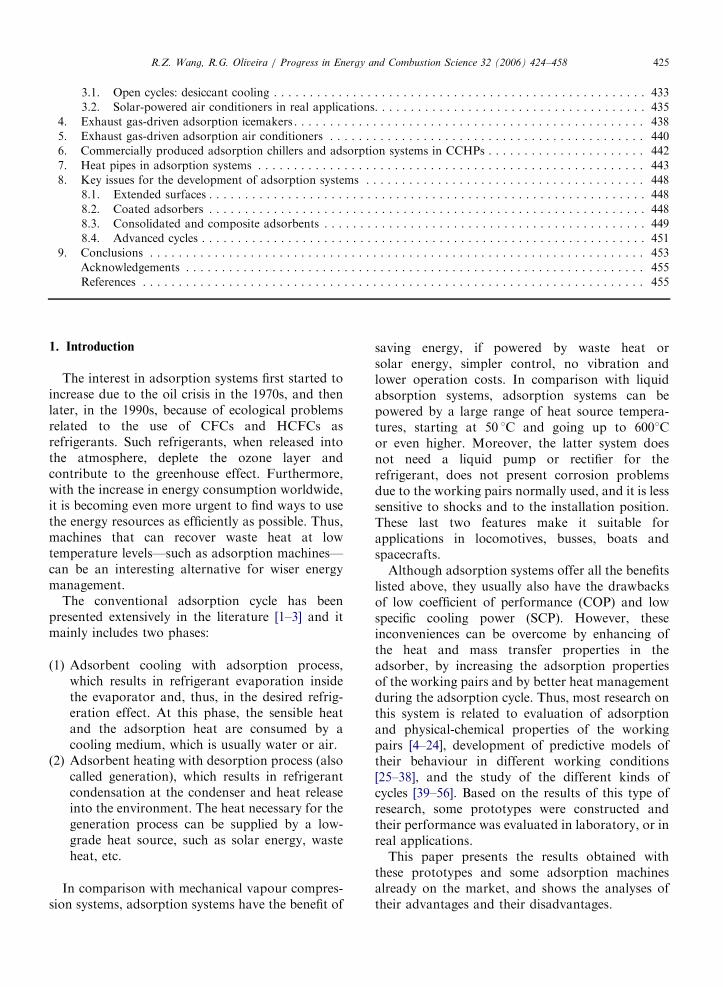
Fig. 1. Solar-powered cold box for vaccine preservation [60].
R.Z. Wang, R.G. Oliveira / Progress in Energy and Combustion Science 32 (2006) 424–458426
The prototypes in question were designed to usewaste heat or solar energy as the main heat source.The applications under examination are ice makingand air conditioning. Air conditioning systems arethose with closed cycles as well as those systemswith open cycles, such as in desiccant systems.
The alternatives already studied to increase theperformance of the machines are also presented;they mainly include the use of advanced typesorption cycles to improve the internal heatmanagement and heat transfer intensification withinthe adsorber, to improve the SCP.
2. Solar-powered adsorption icemakers
Sites with high insolation usually have a largedemand for cooling to preserve food, drugs andvaccines, and considerable research has been de-voted to develop machines that could employ solarenergy efficiently for such purposes. The develop-ment of sorption refrigeration systems powered bysolar energy emerged in the late 1970s, following thepioneering work of Tchernev [57], who studied abasic solid sorption cycle with the working pairzeolite–water. Since then, a number of studies havebeen carried out, both numerically and experimen-tally; but the costs of these systems still make themnon-competitive for commercialisation. Therefore,some research has focussed on cost reduction andon the increase of the efficiency of the machines, andpromising results have already been obtained.
Based on the results of a previous study [58], Ponsand Guilleminot [59] concluded that solid sorption
systems could be the basis for efficient solar-powered refrigerators, and they developed a proto-type with the pair activated carbon–methanol. Thismachine produced almost 6 kg of ice per m2 of solarpanel when the insolation was about 20MJday�1,with a solar COP of 0.12. This rate of ice productionremains one of the highest obtained by a solar-powered icemaker.
Critoph [60] mentioned a solar vaccine refrig-erator studied in his laboratory in the early 1990s[61]. Such machine, shown in Fig. 1, could maintainthe cold box at 0 1C during the daytime, after oneadsorption cycle, performed during the previousnight. According to this author, although the COPand ice production of this machine (which used thepair activated carbon–ammonia), was less thanthose produced by a machine with the pair activatedcarbon–methanol, the former is less sensitive tosmall leakages, which makes it more reliable forapplication in remote areas where maintenance isnot readily available.
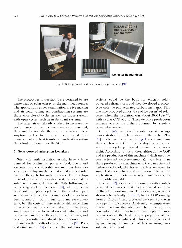
Li et al. [62] performed experiments with a solar-powered ice maker that had activated carbon–methanol as working pair. This icemaker, which isshown schematically in Fig. 2, had a COP rangingfrom 0.12 to 0.14, and produced between 5 and 6 kgof ice per m2 of collector. Analysing the temperaturegradient within the adsorbent bed, the authorsconcluded that in order to improve the performanceof this system, the heat transfer properties of theadsorber must be enhanced. This could be achievedby increasing the number of fins or using con-solidated adsorbent.
ARTICLE IN PRESS
Fig. 2. Scheme of the solar-powered adsorption icemaker: (1) adsorbent bed; (2) glass cover; (3) damper; (4) insulation; (5) pressure gauge;
(6) temperature gauges; (7) valves; (8) evaporator; (9) condenser; (10) refrigerant reservoir; (11) ice box [62].
R.Z. Wang, R.G. Oliveira / Progress in Energy and Combustion Science 32 (2006) 424–458 427
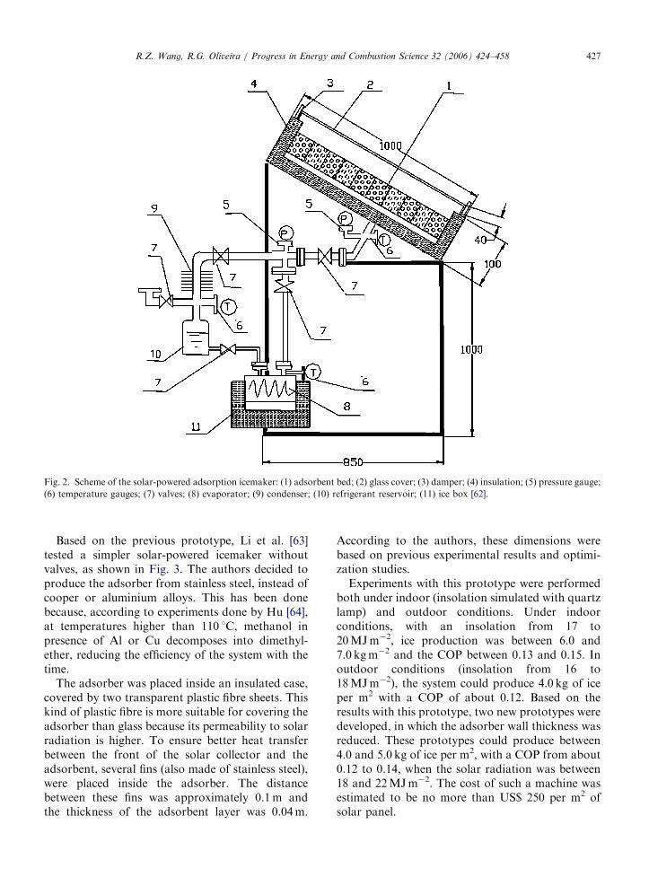
Based on the previous prototype, Li et al. [63]tested a simpler solar-powered icemaker withoutvalves, as shown in Fig. 3. The authors decided toproduce the adsorber from stainless steel, instead ofcooper or aluminium alloys. This has been donebecause, according to experiments done by Hu [64],at temperatures higher than 110 1C, methanol inpresence of Al or Cu decomposes into dimethyl-ether, reducing the efficiency of the system with thetime.
The adsorber was placed inside an insulated case,covered by two transparent plastic fibre sheets. Thiskind of plastic fibre is more suitable for covering theadsorber than glass because its permeability to solarradiation is higher. To ensure better heat transferbetween the front of the solar collector and theadsorbent, several fins (also made of stainless steel),were placed inside the adsorber. The distancebetween these fins was approximately 0.1m andthe thickness of the adsorbent layer was 0.04m.
According to the authors, these dimensions werebased on previous experimental results and optimi-zation studies.
Experiments with this prototype were performedboth under indoor (insolation simulated with quartzlamp) and outdoor conditions. Under indoorconditions, with an insolation from 17 to20MJm�2, ice production was between 6.0 and7.0 kgm�2 and the COP between 0.13 and 0.15. Inoutdoor conditions (insolation from 16 to18MJm�2), the system could produce 4.0 kg of iceper m2 with a COP of about 0.12. Based on theresults with this prototype, two new prototypes weredeveloped, in which the adsorber wall thickness wasreduced. These prototypes could produce between4.0 and 5.0 kg of ice per m2, with a COP from about0.12 to 0.14, when the solar radiation was between18 and 22MJm�2. The cost of such a machine wasestimated to be no more than US$ 250 per m2 ofsolar panel.
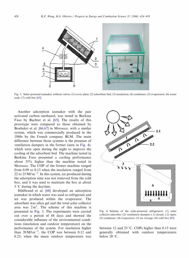
ARTICLE IN PRESS
Fig. 4. Scheme of the solar-powered refrigerator: (1) solar
collector/adsorber; (2) ventilation dampers (.1) closed, (.2) open;
(3) condenser; (4) evaporator; (5) ice storage; (6) cold box [65].
Fig. 3. Solar-powered icemaker without valves: (1) cover plate; (2) adsorbent bed; (3) insulation; (4) condenser; (5) evaporator; (6) water
tank; (7) cold box [63].
R.Z. Wang, R.G. Oliveira / Progress in Energy and Combustion Science 32 (2006) 424–458428
Another adsorption icemaker with the pairactivated carbon–methanol, was tested in BurkinaFaso by Buchter et al. [65]. The results of thisprototype were compared to those obtained byBoubakri et al. [66,67] in Morocco, with a similarsystem, which was commercially produced in the1980s by the French company BLM. The maindifference between those systems is the presence ofventilation dampers in the former (seen in Fig. 4),which were open during the night to improve thecooling of the adsorbent bed. The machine tested inBurkina Faso presented a cooling performanceabout 35% higher than the machine tested inMorocco. The COP of the former machine rangedfrom 0.09 to 0.13 when the insolation ranged from22 to 25MJm�2. In this system, ice produced duringthe adsorption time was not removed from the coldbox, and it was used to maintain the box at about5 1C during the daytime.
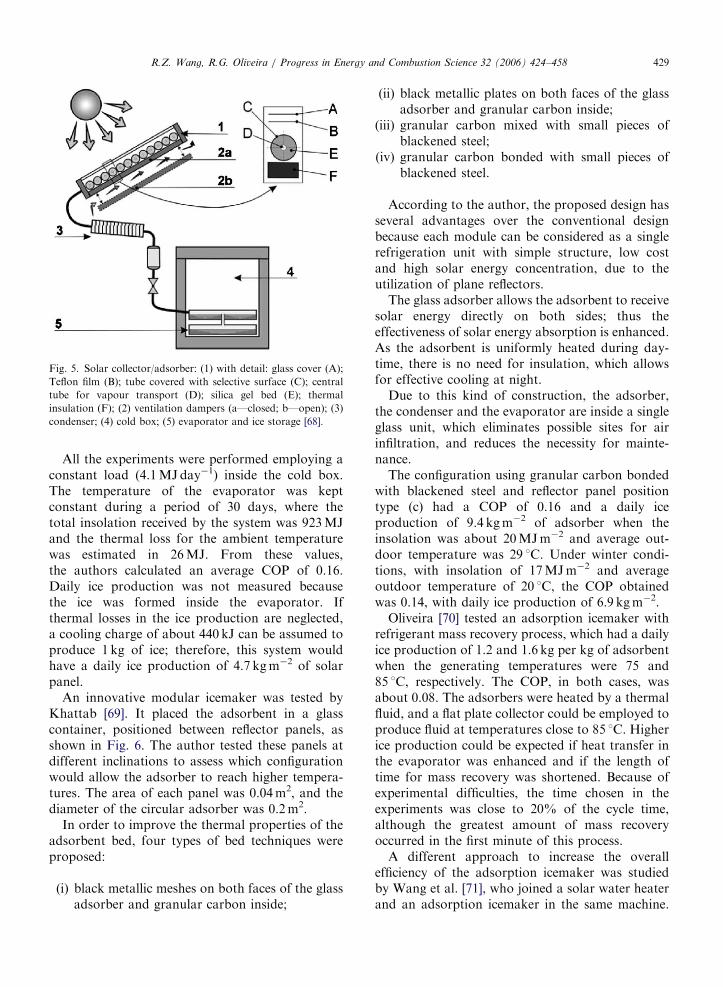
Hildbrand et al. [68] developed an adsorptionicemaker in which water was used as refrigerant andice was produced within the evaporator. Theadsorbent was silica gel and the total solar collectorarea was 2m2. The scheme of this machine ispresented in Fig. 5. The experiments were carriedout over a period of 68 days and showed theconsiderable influence of the environmental condi-tions (insolation and outdoor temperature) on theperformance of the system. For insolation higherthan 20MJm�2, the COP was between 0.12 and0.23; when the mean outdoor temperature was
between 12 and 25 1C. COPs higher than 0.15 weregenerally obtained with outdoor temperaturesbelow 20 1C.
ARTICLE IN PRESS
Fig. 5. Solar collector/adsorber: (1) with detail: glass cover (A);
Teflon film (B); tube covered with selective surface (C); central
tube for vapour transport (D); silica gel bed (E); thermal
insulation (F); (2) ventilation dampers (a—closed; b—open); (3)
condenser; (4) cold box; (5) evaporator and ice storage [68].
R.Z. Wang, R.G. Oliveira / Progress in Energy and Combustion Science 32 (2006) 424–458 429
All the experiments were performed employing aconstant load (4.1MJday�1) inside the cold box.The temperature of the evaporator was keptconstant during a period of 30 days, where thetotal insolation received by the system was 923MJand the thermal loss for the ambient temperaturewas estimated in 26MJ. From these values,the authors calculated an average COP of 0.16.Daily ice production was not measured becausethe ice was formed inside the evaporator. Ifthermal losses in the ice production are neglected,a cooling charge of about 440 kJ can be assumed toproduce 1 kg of ice; therefore, this system wouldhave a daily ice production of 4.7 kgm�2 of solarpanel.
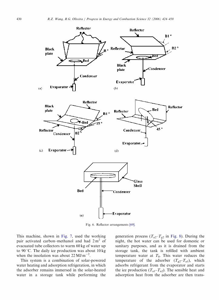
An innovative modular icemaker was tested byKhattab [69]. It placed the adsorbent in a glasscontainer, positioned between reflector panels, asshown in Fig. 6. The author tested these panels atdifferent inclinations to assess which configurationwould allow the adsorber to reach higher tempera-tures. The area of each panel was 0.04m2, and thediameter of the circular adsorber was 0.2m2.
In order to improve the thermal properties of theadsorbent bed, four types of bed techniques wereproposed:
(i)
black metallic meshes on both faces of the glassadsorber and granular carbon inside;(ii)
black metallic plates on both faces of the glassadsorber and granular carbon inside;(iii)
granular carbon mixed with small pieces ofblackened steel;(iv)
granular carbon bonded with small pieces ofblackened steel.According to the author, the proposed design hasseveral advantages over the conventional designbecause each module can be considered as a singlerefrigeration unit with simple structure, low costand high solar energy concentration, due to theutilization of plane reflectors.
The glass adsorber allows the adsorbent to receivesolar energy directly on both sides; thus theeffectiveness of solar energy absorption is enhanced.As the adsorbent is uniformly heated during day-time, there is no need for insulation, which allowsfor effective cooling at night.
Due to this kind of construction, the adsorber,the condenser and the evaporator are inside a singleglass unit, which eliminates possible sites for airinfiltration, and reduces the necessity for mainte-nance.
The configuration using granular carbon bondedwith blackened steel and reflector panel positiontype (c) had a COP of 0.16 and a daily iceproduction of 9.4 kgm�2 of adsorber when theinsolation was about 20MJm�2 and average out-door temperature was 29 1C. Under winter condi-tions, with insolation of 17MJm�2 and averageoutdoor temperature of 20 1C, the COP obtainedwas 0.14, with daily ice production of 6.9 kgm�2.
Oliveira [70] tested an adsorption icemaker withrefrigerant mass recovery process, which had a dailyice production of 1.2 and 1.6 kg per kg of adsorbentwhen the generating temperatures were 75 and85 1C, respectively. The COP, in both cases, wasabout 0.08. The adsorbers were heated by a thermalfluid, and a flat plate collector could be employed toproduce fluid at temperatures close to 85 1C. Higherice production could be expected if heat transfer inthe evaporator was enhanced and if the length oftime for mass recovery was shortened. Because ofexperimental difficulties, the time chosen in theexperiments was close to 20% of the cycle time,although the greatest amount of mass recoveryoccurred in the first minute of this process.
A different approach to increase the overallefficiency of the adsorption icemaker was studiedby Wang et al. [71], who joined a solar water heaterand an adsorption icemaker in the same machine.
ARTICLE IN PRESS
Fig. 6. Reflector arrangements [69].
R.Z. Wang, R.G. Oliveira / Progress in Energy and Combustion Science 32 (2006) 424–458430
This machine, shown in Fig. 7, used the workingpair activated carbon–methanol and had 2m2 ofevacuated tube collectors to warm 60 kg of water upto 90 1C. The daily ice production was about 10 kgwhen the insolation was about 22MJm�2.
This system is a combination of solar-poweredwater heating and adsorption refrigeration, in whichthe adsorber remains immersed in the solar-heatedwater in a storage tank while performing the
generation process (Ta2–Tg2 in Fig. 8). During thenight, the hot water can be used for domestic orsanitary purposes, and as it is drained from thestorage tank, the tank is refilled with ambienttemperature water at T0. This water reduces thetemperature of the adsorber (Tg2–Ta1), whichadsorbs refrigerant from the evaporator and startsthe ice production (Ta1–Ta2). The sensible heat andadsorption heat from the adsorber are then trans-
ARTICLE IN PRESS
Fig. 7. Scheme of the solar-powered water heater and refrig-
erator: (1) solar collector; (2) water pipe; (3) adsorber; (4)
condenser; (5) evaporator; (6) refrigerator (with cold storage); (7)
hot water storage tank [71].
Fig. 8. Clapeyron diagram for combined water heating and
sorption refrigeration system with heat recovery.
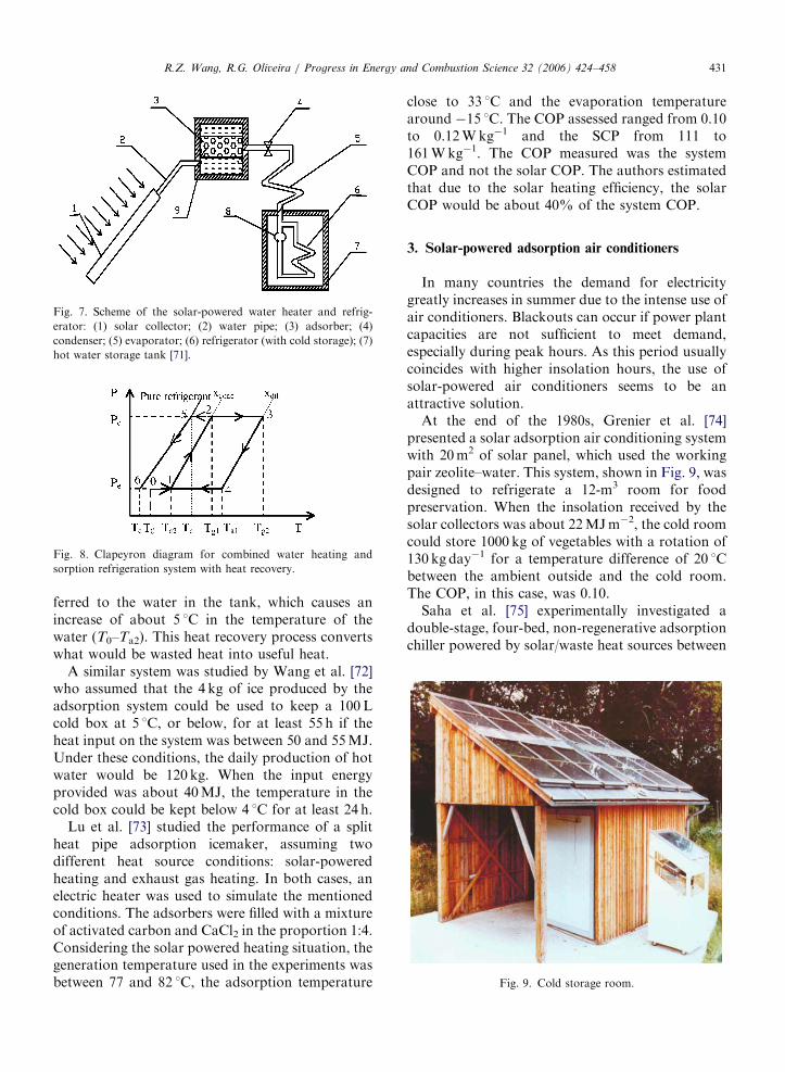
Fig. 9. Cold storage room.
R.Z. Wang, R.G. Oliveira / Progress in Energy and Combustion Science 32 (2006) 424–458 431
ferred to the water in the tank, which causes anincrease of about 5 1C in the temperature of thewater (T0–Ta2). This heat recovery process convertswhat would be wasted heat into useful heat.
A similar system was studied by Wang et al. [72]who assumed that the 4 kg of ice produced by theadsorption system could be used to keep a 100Lcold box at 5 1C, or below, for at least 55 h if theheat input on the system was between 50 and 55MJ.Under these conditions, the daily production of hotwater would be 120 kg. When the input energyprovided was about 40MJ, the temperature in thecold box could be kept below 4 1C for at least 24 h.
Lu et al. [73] studied the performance of a splitheat pipe adsorption icemaker, assuming twodifferent heat source conditions: solar-poweredheating and exhaust gas heating. In both cases, anelectric heater was used to simulate the mentionedconditions. The adsorbers were filled with a mixtureof activated carbon and CaCl2 in the proportion 1:4.Considering the solar powered heating situation, thegeneration temperature used in the experiments wasbetween 77 and 82 1C, the adsorption temperature
close to 33 1C and the evaporation temperaturearound �15 1C. The COP assessed ranged from 0.10to 0.12Wkg�1 and the SCP from 111 to161Wkg�1. The COP measured was the systemCOP and not the solar COP. The authors estimatedthat due to the solar heating efficiency, the solarCOP would be about 40% of the system COP.
3. Solar-powered adsorption air conditioners
In many countries the demand for electricitygreatly increases in summer due to the intense use ofair conditioners. Blackouts can occur if power plantcapacities are not sufficient to meet demand,especially during peak hours. As this period usuallycoincides with higher insolation hours, the use ofsolar-powered air conditioners seems to be anattractive solution.
At the end of the 1980s, Grenier et al. [74]presented a solar adsorption air conditioning systemwith 20m2 of solar panel, which used the workingpair zeolite–water. This system, shown in Fig. 9, wasdesigned to refrigerate a 12-m3 room for foodpreservation. When the insolation received by thesolar collectors was about 22MJm�2, the cold roomcould store 1000 kg of vegetables with a rotation of130 kg day�1 for a temperature difference of 20 1Cbetween the ambient outside and the cold room.The COP, in this case, was 0.10.
Saha et al. [75] experimentally investigated adouble-stage, four-bed, non-regenerative adsorptionchiller powered by solar/waste heat sources between
ARTICLE IN PRESS
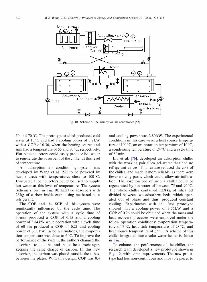
Fig. 10. Scheme of the adsorption air conditioner [52].
R.Z. Wang, R.G. Oliveira / Progress in Energy and Combustion Science 32 (2006) 424–458432
50 and 70 1C. The prototype studied produced coldwater at 10 1C and had a cooling power of 3.2 kWwith a COP of 0.36, when the heating source andsink had a temperature of 55 and 30 1C, respectively.Flat plate collectors could easily produce hot waterto regenerate the adsorbent of the chiller at this levelof temperature.
An adsorption air conditioning system wasdeveloped by Wang et al. [52] to be powered byheat sources with temperatures close to 100 1C.Evacuated tube collectors could be used to supplyhot water at this level of temperature. The system(scheme shown in Fig. 10) had two adsorbers with26 kg of carbon inside each, using methanol as arefrigerant.
The COP and the SCP of this system weresignificantly influenced by the cycle time. Theoperation of the system with a cycle time of30min produced a COP of 0.15 and a coolingpower of 3.84 kW while operation with a cycle timeof 60min produced a COP of 0.21 and coolingpower of 3.03 kW. In both situations, the evapora-tion temperature was close to 6 1C. To improve theperformance of the system, the authors changed theadsorbers to a tube and plate heat exchanger,keeping the same charge of carbon. In this newadsorber, the carbon was placed outside the tubes,between the plates. With this design, COP was 0.4
and cooling power was 3.80 kW. The experimentalconditions in this case were: a heat source tempera-ture of 100 1C, an evaporation temperature of 10 1C,a condensing temperature of 24 1C and a cycle timeof 50min.
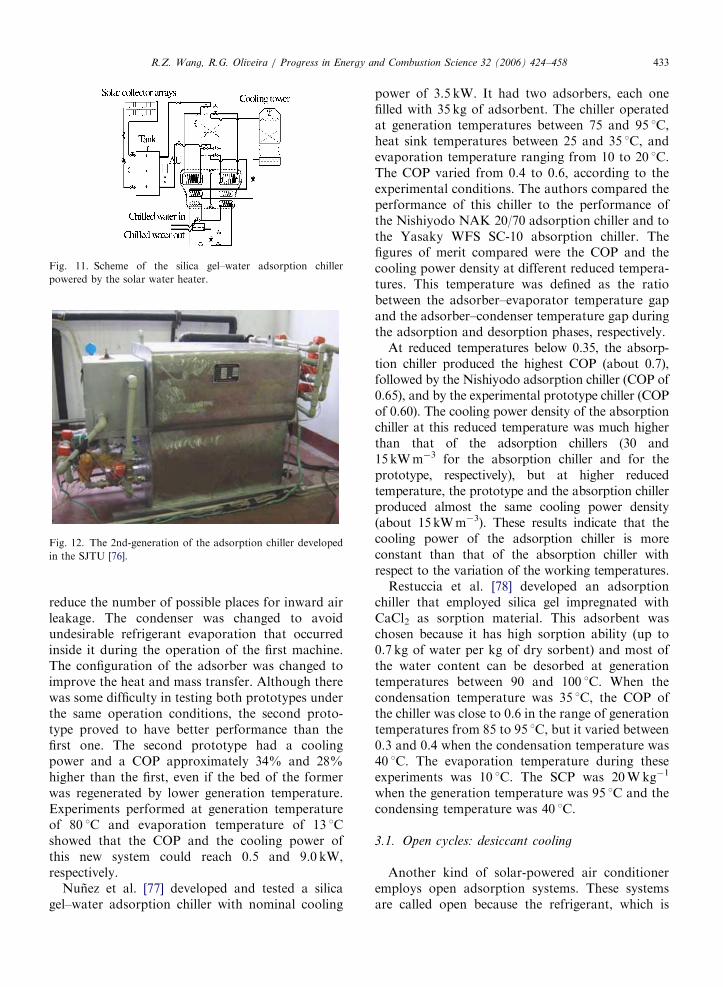
Liu et al. [76], developed an adsorption chillerwith the working pair silica gel–water that had norefrigerant valves. This feature reduced the cost ofthe chiller, and made it more reliable, as there werefewer moving parts, which could allow air infiltra-tion. The sorption bed of such a chiller could beregenerated by hot water of between 75 and 90 1C.The whole chiller contained 52.8 kg of silica geldivided between two adsorbent beds, which oper-ated out of phase and thus, produced constantcooling. Experiments with the first prototypeshowed that a cooling power of 3.56 kW and aCOP of 0.26 could be obtained when the mass andheat recovery processes were employed under thefollow operation conditions: evaporation tempera-ture of 7 1C, heat sink temperature of 28 1C, andheat source temperature of 85 1C. A scheme of thischiller integrated into a solar water heater is shownin Fig. 11.
To enhance the performance of the chiller, theresearch team developed a new prototype shown inFig. 12, with some improvements. The new proto-type had less non-continuous and movable pieces to
ARTICLE IN PRESS
Fig. 11. Scheme of the silica gel–water adsorption chiller
powered by the solar water heater.
Fig. 12. The 2nd-generation of the adsorption chiller developed
in the SJTU [76].
R.Z. Wang, R.G. Oliveira / Progress in Energy and Combustion Science 32 (2006) 424–458 433
reduce the number of possible places for inward airleakage. The condenser was changed to avoidundesirable refrigerant evaporation that occurredinside it during the operation of the first machine.The configuration of the adsorber was changed toimprove the heat and mass transfer. Although therewas some difficulty in testing both prototypes underthe same operation conditions, the second proto-type proved to have better performance than thefirst one. The second prototype had a coolingpower and a COP approximately 34% and 28%higher than the first, even if the bed of the formerwas regenerated by lower generation temperature.Experiments performed at generation temperatureof 80 1C and evaporation temperature of 13 1Cshowed that the COP and the cooling power ofthis new system could reach 0.5 and 9.0 kW,respectively.
Nunez et al. [77] developed and tested a silicagel–water adsorption chiller with nominal cooling
power of 3.5 kW. It had two adsorbers, each onefilled with 35 kg of adsorbent. The chiller operatedat generation temperatures between 75 and 95 1C,heat sink temperatures between 25 and 35 1C, andevaporation temperature ranging from 10 to 20 1C.The COP varied from 0.4 to 0.6, according to theexperimental conditions. The authors compared theperformance of this chiller to the performance ofthe Nishiyodo NAK 20/70 adsorption chiller and tothe Yasaky WFS SC-10 absorption chiller. Thefigures of merit compared were the COP and thecooling power density at different reduced tempera-tures. This temperature was defined as the ratiobetween the adsorber–evaporator temperature gapand the adsorber–condenser temperature gap duringthe adsorption and desorption phases, respectively.
At reduced temperatures below 0.35, the absorp-tion chiller produced the highest COP (about 0.7),followed by the Nishiyodo adsorption chiller (COP of0.65), and by the experimental prototype chiller (COPof 0.60). The cooling power density of the absorptionchiller at this reduced temperature was much higherthan that of the adsorption chillers (30 and15kWm�3 for the absorption chiller and for theprototype, respectively), but at higher reducedtemperature, the prototype and the absorption chillerproduced almost the same cooling power density(about 15kWm�3). These results indicate that thecooling power of the adsorption chiller is moreconstant than that of the absorption chiller withrespect to the variation of the working temperatures.
Restuccia et al. [78] developed an adsorptionchiller that employed silica gel impregnated withCaCl2 as sorption material. This adsorbent waschosen because it has high sorption ability (up to0.7 kg of water per kg of dry sorbent) and most ofthe water content can be desorbed at generationtemperatures between 90 and 100 1C. When thecondensation temperature was 35 1C, the COP ofthe chiller was close to 0.6 in the range of generationtemperatures from 85 to 95 1C, but it varied between0.3 and 0.4 when the condensation temperature was40 1C. The evaporation temperature during theseexperiments was 10 1C. The SCP was 20Wkg�1
when the generation temperature was 95 1C and thecondensing temperature was 40 1C.
3.1. Open cycles: desiccant cooling
Another kind of solar-powered air conditioneremploys open adsorption systems. These systemsare called open because the refrigerant, which is
ARTICLE IN PRESS
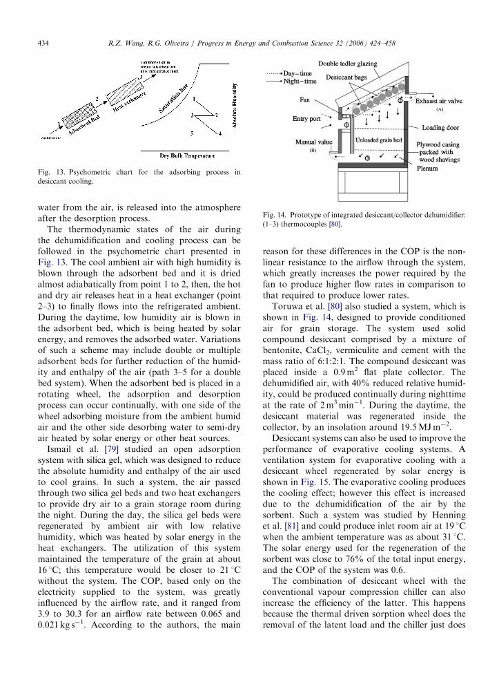
Fig. 13. Psychometric chart for the adsorbing process in
desiccant cooling.
Fig. 14. Prototype of integrated desiccant/collector dehumidifier:
(1–3) thermocouples [80].
R.Z. Wang, R.G. Oliveira / Progress in Energy and Combustion Science 32 (2006) 424–458434
water from the air, is released into the atmosphereafter the desorption process.
The thermodynamic states of the air duringthe dehumidification and cooling process can befollowed in the psychometric chart presented inFig. 13. The cool ambient air with high humidity isblown through the adsorbent bed and it is driedalmost adiabatically from point 1 to 2, then, the hotand dry air releases heat in a heat exchanger (point2–3) to finally flows into the refrigerated ambient.During the daytime, low humidity air is blown inthe adsorbent bed, which is being heated by solarenergy, and removes the adsorbed water. Variationsof such a scheme may include double or multipleadsorbent beds for further reduction of the humid-ity and enthalpy of the air (path 3–5 for a doublebed system). When the adsorbent bed is placed in arotating wheel, the adsorption and desorptionprocess can occur continually, with one side of thewheel adsorbing moisture from the ambient humidair and the other side desorbing water to semi-dryair heated by solar energy or other heat sources.
Ismail et al. [79] studied an open adsorptionsystem with silica gel, which was designed to reducethe absolute humidity and enthalpy of the air usedto cool grains. In such a system, the air passedthrough two silica gel beds and two heat exchangersto provide dry air to a grain storage room duringthe night. During the day, the silica gel beds wereregenerated by ambient air with low relativehumidity, which was heated by solar energy in theheat exchangers. The utilization of this systemmaintained the temperature of the grain at about16 1C; this temperature would be closer to 21 1Cwithout the system. The COP, based only on theelectricity supplied to the system, was greatlyinfluenced by the airflow rate, and it ranged from3.9 to 30.3 for an airflow rate between 0.065 and0.021 kg s�1. According to the authors, the main
reason for these differences in the COP is the non-linear resistance to the airflow through the system,which greatly increases the power required by thefan to produce higher flow rates in comparison tothat required to produce lower rates.
Toruwa et al. [80] also studied a system, which isshown in Fig. 14, designed to provide conditionedair for grain storage. The system used solidcompound desiccant comprised by a mixture ofbentonite, CaCl2, vermiculite and cement with themass ratio of 6:1:2:1. The compound desiccant wasplaced inside a 0.9m2 flat plate collector. Thedehumidified air, with 40% reduced relative humid-ity, could be produced continually during nighttimeat the rate of 2m3min�1. During the daytime, thedesiccant material was regenerated inside thecollector, by an insolation around 19.5MJm�2.
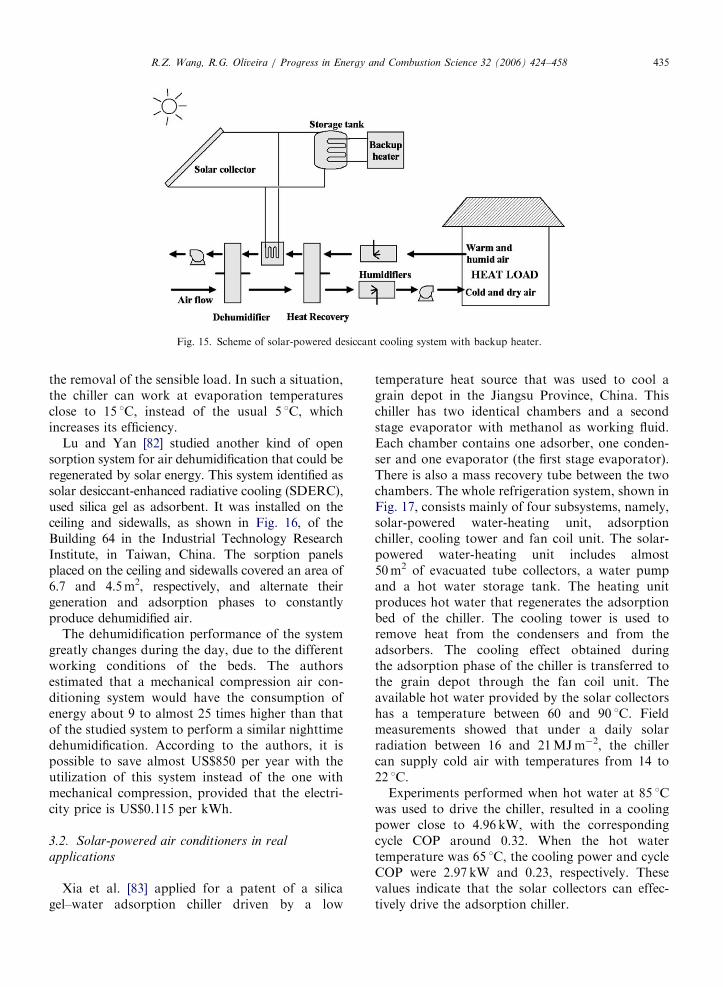
Desiccant systems can also be used to improve theperformance of evaporative cooling systems. Aventilation system for evaporative cooling with adesiccant wheel regenerated by solar energy isshown in Fig. 15. The evaporative cooling producesthe cooling effect; however this effect is increaseddue to the dehumidification of the air by thesorbent. Such a system was studied by Henninget al. [81] and could produce inlet room air at 19 1Cwhen the ambient temperature was as about 31 1C.The solar energy used for the regeneration of thesorbent was close to 76% of the total input energy,and the COP of the system was 0.6.
The combination of desiccant wheel with theconventional vapour compression chiller can alsoincrease the efficiency of the latter. This happensbecause the thermal driven sorption wheel does theremoval of the latent load and the chiller just does
ARTICLE IN PRESS
Fig. 15. Scheme of solar-powered desiccant cooling system with backup heater.
R.Z. Wang, R.G. Oliveira / Progress in Energy and Combustion Science 32 (2006) 424–458 435
the removal of the sensible load. In such a situation,the chiller can work at evaporation temperaturesclose to 15 1C, instead of the usual 5 1C, whichincreases its efficiency.
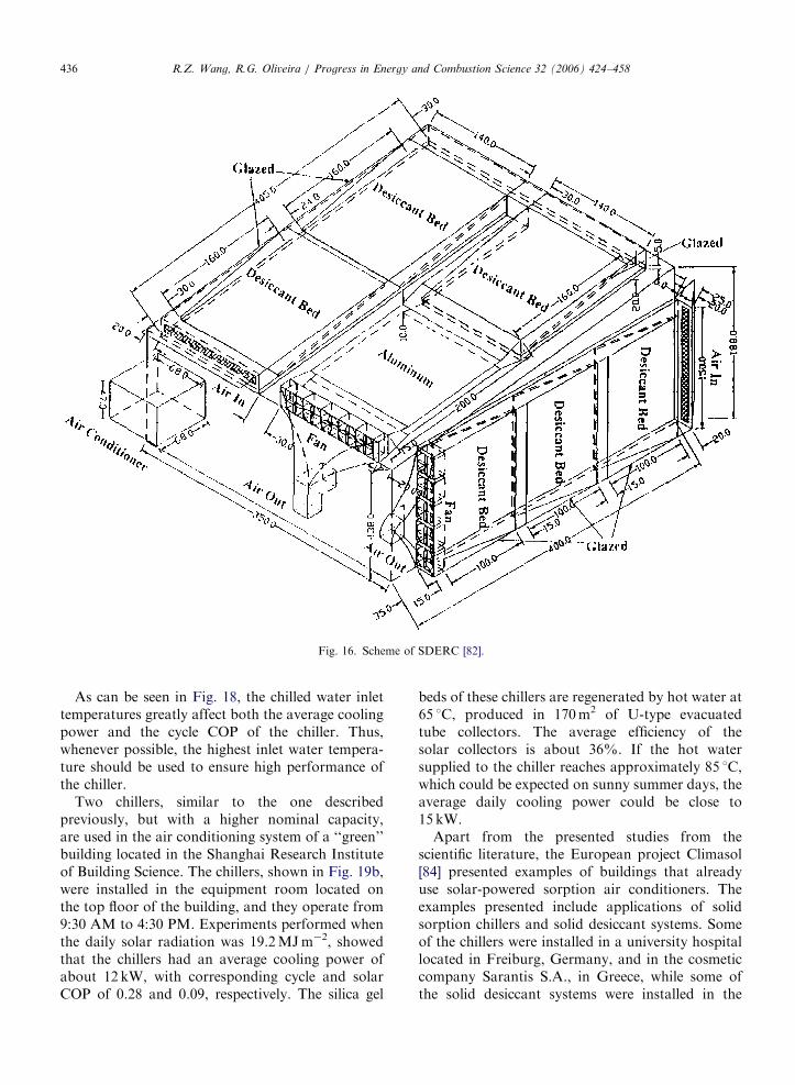
Lu and Yan [82] studied another kind of opensorption system for air dehumidification that could beregenerated by solar energy. This system identified assolar desiccant-enhanced radiative cooling (SDERC),used silica gel as adsorbent. It was installed on theceiling and sidewalls, as shown in Fig. 16, of theBuilding 64 in the Industrial Technology ResearchInstitute, in Taiwan, China. The sorption panelsplaced on the ceiling and sidewalls covered an area of6.7 and 4.5m2, respectively, and alternate theirgeneration and adsorption phases to constantlyproduce dehumidified air.
The dehumidification performance of the systemgreatly changes during the day, due to the differentworking conditions of the beds. The authorsestimated that a mechanical compression air con-ditioning system would have the consumption ofenergy about 9 to almost 25 times higher than thatof the studied system to perform a similar nighttimedehumidification. According to the authors, it ispossible to save almost US$850 per year with theutilization of this system instead of the one withmechanical compression, provided that the electri-city price is US$0.115 per kWh.
3.2. Solar-powered air conditioners in real
applications
Xia et al. [83] applied for a patent of a silicagel–water adsorption chiller driven by a low
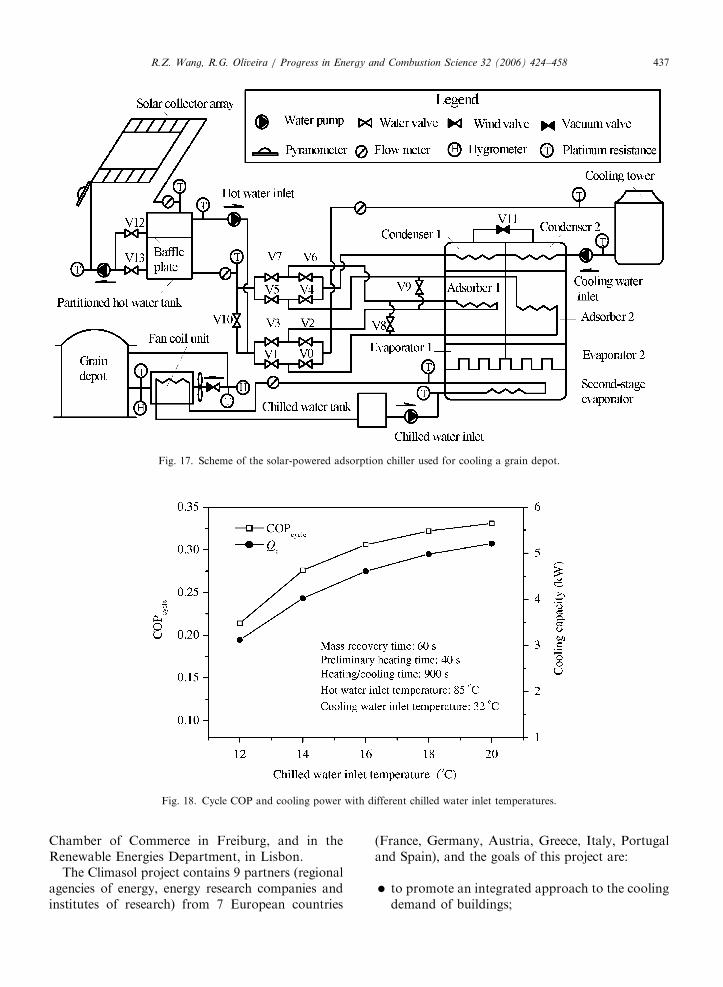
temperature heat source that was used to cool agrain depot in the Jiangsu Province, China. Thischiller has two identical chambers and a secondstage evaporator with methanol as working fluid.Each chamber contains one adsorber, one conden-ser and one evaporator (the first stage evaporator).There is also a mass recovery tube between the twochambers. The whole refrigeration system, shown inFig. 17, consists mainly of four subsystems, namely,solar-powered water-heating unit, adsorptionchiller, cooling tower and fan coil unit. The solar-powered water-heating unit includes almost50m2 of evacuated tube collectors, a water pumpand a hot water storage tank. The heating unitproduces hot water that regenerates the adsorptionbed of the chiller. The cooling tower is used toremove heat from the condensers and from theadsorbers. The cooling effect obtained duringthe adsorption phase of the chiller is transferred tothe grain depot through the fan coil unit. Theavailable hot water provided by the solar collectorshas a temperature between 60 and 90 1C. Fieldmeasurements showed that under a daily solarradiation between 16 and 21MJm�2, the chillercan supply cold air with temperatures from 14 to22 1C.
Experiments performed when hot water at 85 1Cwas used to drive the chiller, resulted in a coolingpower close to 4.96 kW, with the correspondingcycle COP around 0.32. When the hot watertemperature was 65 1C, the cooling power and cycleCOP were 2.97 kW and 0.23, respectively. Thesevalues indicate that the solar collectors can effec-tively drive the adsorption chiller.
ARTICLE IN PRESS
Fig. 16. Scheme of SDERC [82].
R.Z. Wang, R.G. Oliveira / Progress in Energy and Combustion Science 32 (2006) 424–458436
As can be seen in Fig. 18, the chilled water inlettemperatures greatly affect both the average coolingpower and the cycle COP of the chiller. Thus,whenever possible, the highest inlet water tempera-ture should be used to ensure high performance ofthe chiller.
Two chillers, similar to the one describedpreviously, but with a higher nominal capacity,are used in the air conditioning system of a ‘‘green’’building located in the Shanghai Research Instituteof Building Science. The chillers, shown in Fig. 19b,were installed in the equipment room located onthe top floor of the building, and they operate from9:30 AM to 4:30 PM. Experiments performed whenthe daily solar radiation was 19.2MJm�2, showedthat the chillers had an average cooling power ofabout 12 kW, with corresponding cycle and solarCOP of 0.28 and 0.09, respectively. The silica gel
beds of these chillers are regenerated by hot water at65 1C, produced in 170m2 of U-type evacuatedtube collectors. The average efficiency of thesolar collectors is about 36%. If the hot watersupplied to the chiller reaches approximately 85 1C,which could be expected on sunny summer days, theaverage daily cooling power could be close to15 kW.
Apart from the presented studies from thescientific literature, the European project Climasol[84] presented examples of buildings that alreadyuse solar-powered sorption air conditioners. Theexamples presented include applications of solidsorption chillers and solid desiccant systems. Someof the chillers were installed in a university hospitallocated in Freiburg, Germany, and in the cosmeticcompany Sarantis S.A., in Greece, while some ofthe solid desiccant systems were installed in the
ARTICLE IN PRESS
Fig. 17. Scheme of the solar-powered adsorption chiller used for cooling a grain depot.
Fig. 18. Cycle COP and cooling power with different chilled water inlet temperatures.
R.Z. Wang, R.G. Oliveira / Progress in Energy and Combustion Science 32 (2006) 424–458 437
Chamber of Commerce in Freiburg, and in theRenewable Energies Department, in Lisbon.
The Climasol project contains 9 partners (regionalagencies of energy, energy research companies andinstitutes of research) from 7 European countries
(France, Germany, Austria, Greece, Italy, Portugaland Spain), and the goals of this project are:
�
to promote an integrated approach to the coolingdemand of buildings;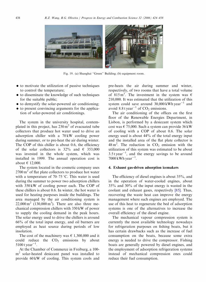
ARTICLE IN PRESS
Fig. 19. (a) Shanghai ‘‘Green’’ Building; (b) equipment room.
R.Z. Wang, R.G. Oliveira / Progress in Energy and Combustion Science 32 (2006) 424–458438
�
to motivate the utilization of passive techniquesto control the temperature; � to disseminate the knowledge of such techniquesfor the suitable public;
� to demystify the solar-powered air conditioning; � to present convincing arguments for the applica-tion of solar-powered air conditionings.
The system in the university hospital, contem-plated in this project, has 230m2 of evacuated tubecollectors that produce hot water used to drive anadsorption chiller with a 70 kW cooling powerduring summer, or to pre-heat the air during winter.The COP of this chiller is about 0.6, the efficiencyof the solar collectors is 32% and h 353,000was invested in the whole system, which wasinstalled in 1999. The annual operation cost isabout h 12,000.
The system located in the cosmetic company uses2700m2 of flat plate collectors to produce hot waterwith a temperature of 70–75 1C. This water is usedduring the summer to power two adsorption chillerswith 350 kW of cooling power each. The COP ofthese chillers is about 0.6. In winter, the hot water isused for heating purposes inside the buildings. Thearea managed by the air conditioning system is22,000m2 (130,000m3). There are also three me-chanical compression chillers with 350 kW of powerto supply the cooling demand in the peak hours.The solar energy used to drive the chillers is around66% of the total input energy, and oil burners areemployed as heat source during periods of lowinsolation.
The cost of the machinery was h 1,300,000 and itcould reduce the CO2 emissions by about5100 t year�1.
At the Chamber of Commerce in Freiburg, a 100-m2 solar-heated desiccant panel was installed toprovide 60 kW of cooling. This system cools and
pre-heats the air during summer and winter,respectively, of two rooms that have a total volumeof 815m3. The investment in the system was h
210,000. It was estimated that the utilization of thissystem could save around 30,000 kWhyear�1 andavoid 8.8 t year�1 of CO2 emissions.
The air conditioning of the offices on the firstfloor of the Renewable Energies Department, inLisbon, is performed by a desiccant system whichcost was h 75,000. Such a system can provide 36 kWof cooling with a COP of about 0.6. The solarenergy used is about 44% of the total energy inputand the installed area of the flat plate collector is48m2. The reduction in CO2 emission with theutilization of this system was estimated to be about3.5 t year�1, and the energy savings to be around7000 kWhyear�1.
4. Exhaust gas-driven adsorption icemakers
The efficiency of diesel engines is about 35%, andin the operation of water-cooled engines, about35% and 30% of the input energy is wasted in thecoolant and exhaust gases, respectively [85]. Thus,recovering the waste heat can improve the energymanagement where such engines are employed. Theuse of this heat to regenerate the bed of adsorptionsystems is one of the alternatives to increase theoverall efficiency of the diesel engine.
The mechanical vapour compression system iscurrently the most available technology nowadaysfor refrigeration purposes on fishing boats, but ithas certain drawbacks such as the increase of fuelconsumption on the boats, because some extraenergy is needed to drive the compressor. Fishingboats are generally powered by diesel engines, andthe employment of adsorption refrigeration systemsinstead of mechanical compression ones couldreduce their fuel consumption.

ARTICLE IN PRESS
Fig. 20. Consolidated carbon block.
R.Z. Wang, R.G. Oliveira / Progress in Energy and Combustion Science 32 (2006) 424–458 439
Wang et al. [86] developed an adsorption system inwhich the sorption beds could be regenerated byexhaust gases of diesel engines. This system wasdesigned for ice production, and the working pairemployed was activated carbon and methanol. Theexhaust gases holding a temperature of about 500 1Cheated water in a heat exchanger and the water wasused to heat the adsorbent at the generation phase.The temperature of the hot water was adjusted toalways be lower than 120 1C, because methanol, whenin contact with activated carbon, is not stable attemperatures higher than this. The authors usedsolidified adsorbent, which is shown in Fig. 20,instead of granular one because of the difference inthe heat transfer coefficient of these two materials (99and 25Wm�2K�1, respectively). Although the heattransfer performance of the solidified adsorbent wassuperior to that of the granular one, the mass transferwas inferior due to its low permeability. The authorsstressed the importance of refrigerant flow channelsinside the adsorbent to ensure that the rates ofdesorption and adsorption would not be influencedby the low permeability.
The experiments with this prototype were per-formed with and without refrigerant mass recovery.The mass recovery proved to increase the iceproduction by 11%. With a cycle time of 72minand an evaporation temperature of �11 1C, the SCPwas 16.8Wkg�1 and the COP was 0.12.
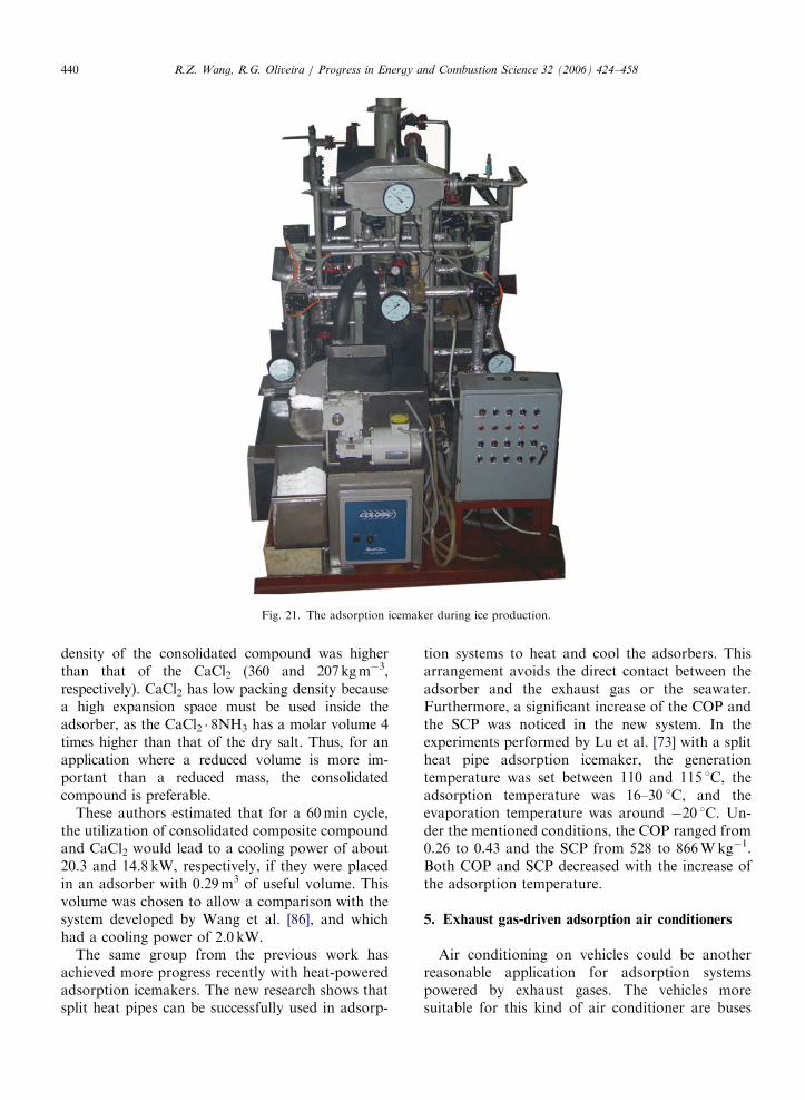
The consolidated carbon block was also used in aprototype developed by Wang and Wang [87]. Theexperiments with this machine employed heat andmass recovery processes to increase the SCP and theCOP. An oil burner simulated the heat from theexhaust gases of a diesel engine. The systemachieved a SCP of 27Wkg�1 with a COP of 0.18,which resulted in a flake ice production from 18 to20 kg h�1 at �7 1C. The Fig. 21 shows a picture ofthe prototype producing flake ice.
Tamainot-Telto and Critoph [88] developed anadsorption system with consolidated carbon blocks,
and utilized ammonia as refrigerant. This systempresented a SCP of 35Wkg�1 and a COP of 0.10when the evaporation temperature was �17 1C, thecondensing temperature was 25 1C and the genera-tion temperature was 105 1C. Assuming that thiscarbon had a density of 713 kgm�3, this systemcould have a cooling power density close to24.9 kWm�3. The authors mention that the utiliza-tion of higher generation temperature and heatrecovery process could lead to higher SCP andCOP.
Wang et al. [89] compared the performance of anadsorption system using different working pairs toidentify the most suitable pair for adsorption icemaking on fishing boats. The pairs compared were:(1) activated carbon and methanol; (2) CaCl2 andammonia; (3) compound adsorbent (80% CaCl2plus 20% activated carbon) and ammonia. The pairactivated carbon–methanol was that from Wanget al. [86]. In the experiment with the pair CaCl2 andammonia, the authors measured the adsorbed massof refrigerant at an evaporation temperature of�15 1C for different expansion ratios (void volumeper filled volume of dry salt) and calculated theexpected cooling capacity. The expansion ratio thatproduced the higher cooling capacity was 2:1. Thecooling capacity was about 889 kJ kg�1, and thecooling density was 185MJm�3. The value obtainedfor the cooling density includes not only the volumeoccupied by the dry salt but also, the void volumenecessary for its expansion.
The compound adsorbent was tested in granularand consolidated form. The granular form pre-sented attenuation in the adsorption performance.Based on the results of their experiments, theauthors mentioned that a moderate agglomerationof the salt during the adsorption process is desirableto keep the adsorption properties stable on succes-sive adsorption cycles, and this agglomeration wasnot observed with the granular compound.
To promote the desired agglomeration, the authorsmixed the compound with cement and produced aconsolidated adsorbent. This compound presentedstable adsorption performance after several adsorp-tion phases and higher packing density. It couldproduce a cooling capacity of about 660kJ kg�1, anda cooling density of 254MJm�3, when the evapora-tion temperature was �15 1C. Although the coolingcapacity obtained with the consolidated compoundwas smaller than that obtained with CaCl2, thecooling density was about 38% higher. The increasein the cooling density happened because the packing
ARTICLE IN PRESS
Fig. 21. The adsorption icemaker during ice production.
R.Z. Wang, R.G. Oliveira / Progress in Energy and Combustion Science 32 (2006) 424–458440
density of the consolidated compound was higherthan that of the CaCl2 (360 and 207kgm�3,respectively). CaCl2 has low packing density becausea high expansion space must be used inside theadsorber, as the CaCl2 � 8NH3 has a molar volume 4times higher than that of the dry salt. Thus, for anapplication where a reduced volume is more im-portant than a reduced mass, the consolidatedcompound is preferable.
These authors estimated that for a 60min cycle,the utilization of consolidated composite compoundand CaCl2 would lead to a cooling power of about20.3 and 14.8 kW, respectively, if they were placedin an adsorber with 0.29m3 of useful volume. Thisvolume was chosen to allow a comparison with thesystem developed by Wang et al. [86], and whichhad a cooling power of 2.0 kW.
The same group from the previous work hasachieved more progress recently with heat-poweredadsorption icemakers. The new research shows thatsplit heat pipes can be successfully used in adsorp-
tion systems to heat and cool the adsorbers. Thisarrangement avoids the direct contact between theadsorber and the exhaust gas or the seawater.Furthermore, a significant increase of the COP andthe SCP was noticed in the new system. In theexperiments performed by Lu et al. [73] with a splitheat pipe adsorption icemaker, the generationtemperature was set between 110 and 115 1C, theadsorption temperature was 16–30 1C, and theevaporation temperature was around �20 1C. Un-der the mentioned conditions, the COP ranged from0.26 to 0.43 and the SCP from 528 to 866Wkg�1.Both COP and SCP decreased with the increase ofthe adsorption temperature.
5. Exhaust gas-driven adsorption air conditioners
Air conditioning on vehicles could be anotherreasonable application for adsorption systemspowered by exhaust gases. The vehicles moresuitable for this kind of air conditioner are buses
ARTICLE IN PRESS
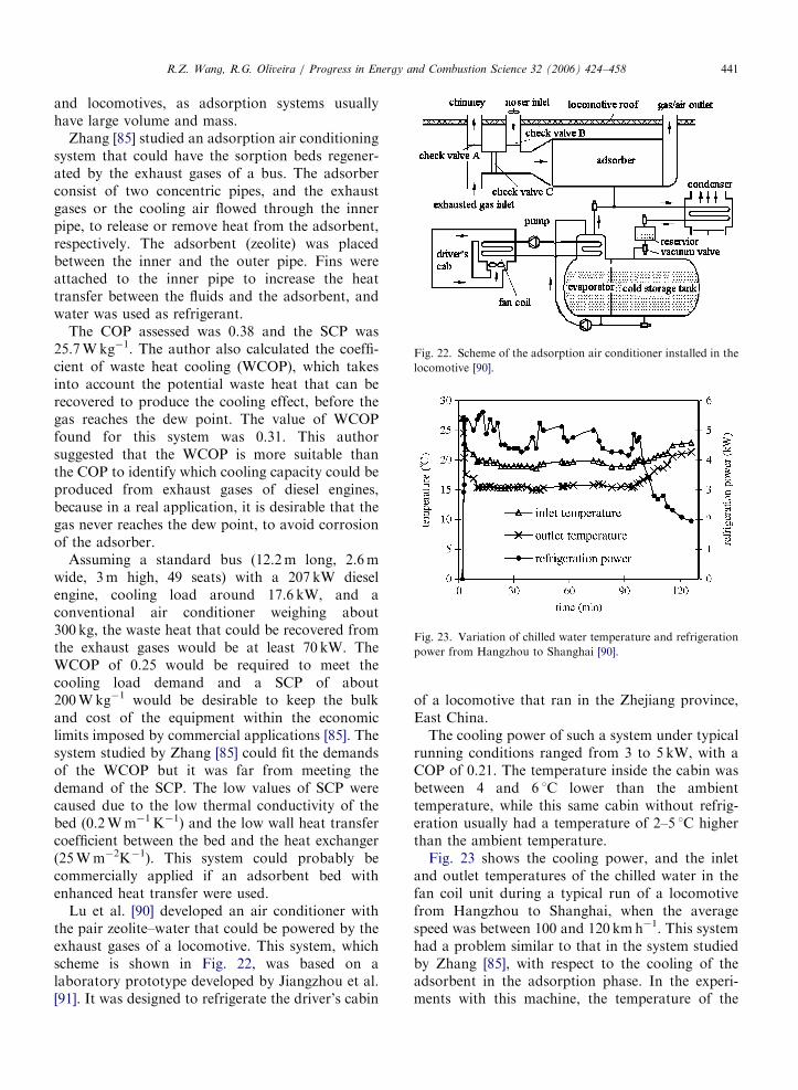
Fig. 22. Scheme of the adsorption air conditioner installed in the
locomotive [90].
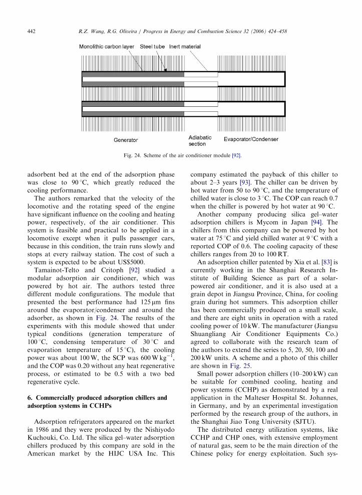
Fig. 23. Variation of chilled water temperature and refrigeration
power from Hangzhou to Shanghai [90].
R.Z. Wang, R.G. Oliveira / Progress in Energy and Combustion Science 32 (2006) 424–458 441
and locomotives, as adsorption systems usuallyhave large volume and mass.
Zhang [85] studied an adsorption air conditioningsystem that could have the sorption beds regener-ated by the exhaust gases of a bus. The adsorberconsist of two concentric pipes, and the exhaustgases or the cooling air flowed through the innerpipe, to release or remove heat from the adsorbent,respectively. The adsorbent (zeolite) was placedbetween the inner and the outer pipe. Fins wereattached to the inner pipe to increase the heattransfer between the fluids and the adsorbent, andwater was used as refrigerant.
The COP assessed was 0.38 and the SCP was25.7Wkg�1. The author also calculated the coeffi-cient of waste heat cooling (WCOP), which takesinto account the potential waste heat that can berecovered to produce the cooling effect, before thegas reaches the dew point. The value of WCOPfound for this system was 0.31. This authorsuggested that the WCOP is more suitable thanthe COP to identify which cooling capacity could beproduced from exhaust gases of diesel engines,because in a real application, it is desirable that thegas never reaches the dew point, to avoid corrosionof the adsorber.
Assuming a standard bus (12.2m long, 2.6mwide, 3m high, 49 seats) with a 207 kW dieselengine, cooling load around 17.6 kW, and aconventional air conditioner weighing about300 kg, the waste heat that could be recovered fromthe exhaust gases would be at least 70 kW. TheWCOP of 0.25 would be required to meet thecooling load demand and a SCP of about200Wkg�1 would be desirable to keep the bulkand cost of the equipment within the economiclimits imposed by commercial applications [85]. Thesystem studied by Zhang [85] could fit the demandsof the WCOP but it was far from meeting thedemand of the SCP. The low values of SCP werecaused due to the low thermal conductivity of thebed (0.2Wm�1K�1) and the low wall heat transfercoefficient between the bed and the heat exchanger(25Wm�2K�1). This system could probably becommercially applied if an adsorbent bed withenhanced heat transfer were used.
Lu et al. [90] developed an air conditioner withthe pair zeolite–water that could be powered by theexhaust gases of a locomotive. This system, whichscheme is shown in Fig. 22, was based on alaboratory prototype developed by Jiangzhou et al.[91]. It was designed to refrigerate the driver’s cabin
of a locomotive that ran in the Zhejiang province,East China.
The cooling power of such a system under typicalrunning conditions ranged from 3 to 5 kW, with aCOP of 0.21. The temperature inside the cabin wasbetween 4 and 6 1C lower than the ambienttemperature, while this same cabin without refrig-eration usually had a temperature of 2–5 1C higherthan the ambient temperature.
Fig. 23 shows the cooling power, and the inletand outlet temperatures of the chilled water in thefan coil unit during a typical run of a locomotivefrom Hangzhou to Shanghai, when the averagespeed was between 100 and 120 kmh�1. This systemhad a problem similar to that in the system studiedby Zhang [85], with respect to the cooling of theadsorbent in the adsorption phase. In the experi-ments with this machine, the temperature of the
ARTICLE IN PRESS
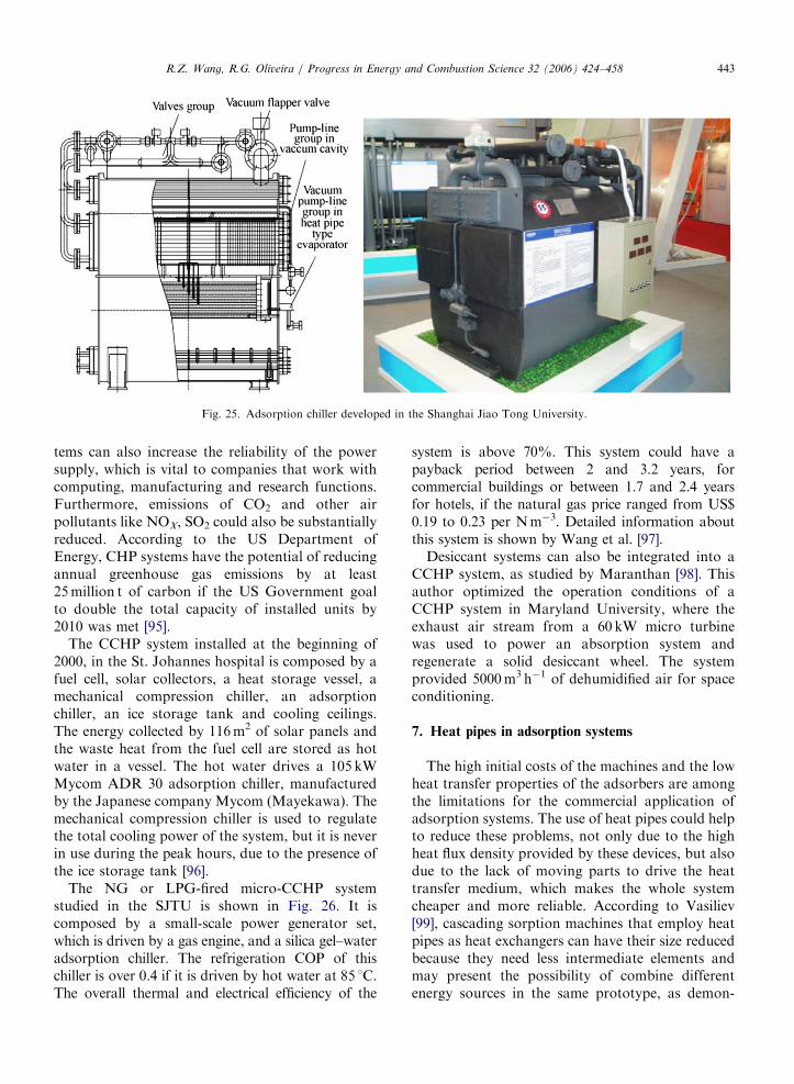
Fig. 24. Scheme of the air conditioner module [92].
R.Z. Wang, R.G. Oliveira / Progress in Energy and Combustion Science 32 (2006) 424–458442
adsorbent bed at the end of the adsorption phasewas close to 90 1C, which greatly reduced thecooling performance.
The authors remarked that the velocity of thelocomotive and the rotating speed of the enginehave significant influence on the cooling and heatingpower, respectively, of the air conditioner. Thissystem is feasible and practical to be applied in alocomotive except when it pulls passenger cars,because in this condition, the train runs slowly andstops at every railway station. The cost of such asystem is expected to be about US$5000.
Tamainot-Telto and Critoph [92] studied amodular adsorption air conditioner, which waspowered by hot air. The authors tested threedifferent module configurations. The module thatpresented the best performance had 125 mm finsaround the evaporator/condenser and around theadsorber, as shown in Fig. 24. The results of theexperiments with this module showed that undertypical conditions (generation temperature of100 1C, condensing temperature of 30 1C andevaporation temperature of 15 1C), the coolingpower was about 100W, the SCP was 600Wkg�1,and the COP was 0.20 without any heat regenerativeprocess, or estimated to be 0.5 with a two bedregenerative cycle.
6. Commercially produced adsorption chillers and
adsorption systems in CCHPs
Adsorption refrigerators appeared on the marketin 1986 and they were produced by the NishiyodoKuchouki, Co. Ltd. The silica gel–water adsorptionchillers produced by this company are sold in theAmerican market by the HIJC USA Inc. This
company estimated the payback of this chiller toabout 2–3 years [93]. The chiller can be driven byhot water from 50 to 90 1C, and the temperature ofchilled water is close to 3 1C. The COP can reach 0.7when the chiller is powered by hot water at 90 1C.
Another company producing silica gel–wateradsorption chillers is Mycom in Japan [94]. Thechillers from this company can be powered by hotwater at 75 1C and yield chilled water at 9 1C with areported COP of 0.6. The cooling capacity of thesechillers ranges from 20 to 100RT.
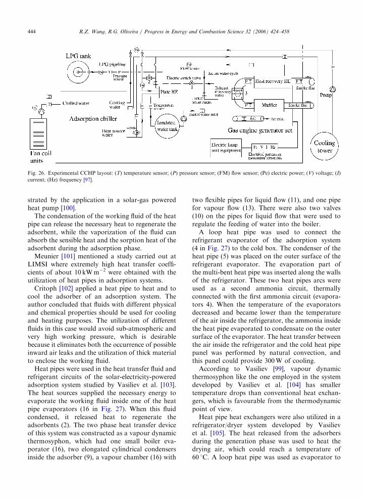
An adsorption chiller patented by Xia et al. [83] iscurrently working in the Shanghai Research In-stitute of Building Science as part of a solar-powered air conditioner, and it is also used at agrain depot in Jiangsu Province, China, for coolinggrain during hot summers. This adsorption chillerhas been commercially produced on a small scale,and there are eight units in operation with a ratedcooling power of 10 kW. The manufacturer (JiangsuShuangliang Air Conditioner Equipments Co.)agreed to collaborate with the research team ofthe authors to extend the series to 5, 20, 50, 100 and200 kW units. A scheme and a photo of this chillerare shown in Fig. 25.
Small power adsorption chillers (10–200 kW) canbe suitable for combined cooling, heating andpower systems (CCHP) as demonstrated by a realapplication in the Malteser Hospital St. Johannes,in Germany, and by an experimental investigationperformed by the research group of the authors, inthe Shanghai Jiao Tong University (SJTU).
The distributed energy utilization systems, likeCCHP and CHP ones, with extensive employmentof natural gas, seem to be the main direction of theChinese policy for energy exploitation. Such sys-
ARTICLE IN PRESS
Fig. 25. Adsorption chiller developed in the Shanghai Jiao Tong University.
R.Z. Wang, R.G. Oliveira / Progress in Energy and Combustion Science 32 (2006) 424–458 443
tems can also increase the reliability of the powersupply, which is vital to companies that work withcomputing, manufacturing and research functions.Furthermore, emissions of CO2 and other airpollutants like NOX, SO2 could also be substantiallyreduced. According to the US Department ofEnergy, CHP systems have the potential of reducingannual greenhouse gas emissions by at least25million t of carbon if the US Government goalto double the total capacity of installed units by2010 was met [95].
The CCHP system installed at the beginning of2000, in the St. Johannes hospital is composed by afuel cell, solar collectors, a heat storage vessel, amechanical compression chiller, an adsorptionchiller, an ice storage tank and cooling ceilings.The energy collected by 116m2 of solar panels andthe waste heat from the fuel cell are stored as hotwater in a vessel. The hot water drives a 105 kWMycom ADR 30 adsorption chiller, manufacturedby the Japanese company Mycom (Mayekawa). Themechanical compression chiller is used to regulatethe total cooling power of the system, but it is neverin use during the peak hours, due to the presence ofthe ice storage tank [96].
The NG or LPG-fired micro-CCHP systemstudied in the SJTU is shown in Fig. 26. It iscomposed by a small-scale power generator set,which is driven by a gas engine, and a silica gel–wateradsorption chiller. The refrigeration COP of thischiller is over 0.4 if it is driven by hot water at 85 1C.The overall thermal and electrical efficiency of the
system is above 70%. This system could have apayback period between 2 and 3.2 years, forcommercial buildings or between 1.7 and 2.4 yearsfor hotels, if the natural gas price ranged from US$0.19 to 0.23 per Nm�3. Detailed information aboutthis system is shown by Wang et al. [97].
Desiccant systems can also be integrated into aCCHP system, as studied by Maranthan [98]. Thisauthor optimized the operation conditions of aCCHP system in Maryland University, where theexhaust air stream from a 60 kW micro turbinewas used to power an absorption system andregenerate a solid desiccant wheel. The systemprovided 5000m3 h�1 of dehumidified air for spaceconditioning.
7. Heat pipes in adsorption systems
The high initial costs of the machines and the lowheat transfer properties of the adsorbers are amongthe limitations for the commercial application ofadsorption systems. The use of heat pipes could helpto reduce these problems, not only due to the highheat flux density provided by these devices, but alsodue to the lack of moving parts to drive the heattransfer medium, which makes the whole systemcheaper and more reliable. According to Vasiliev[99], cascading sorption machines that employ heatpipes as heat exchangers can have their size reducedbecause they need less intermediate elements andmay present the possibility of combine differentenergy sources in the same prototype, as demon-
ARTICLE IN PRESS
Fig. 26. Experimental CCHP layout: (T) temperature sensor; (P) pressure sensor; (FM) flow sensor; (Pe) electric power; (V) voltage; (I)
current; (Hz) frequency [97].
R.Z. Wang, R.G. Oliveira / Progress in Energy and Combustion Science 32 (2006) 424–458444
strated by the application in a solar-gas poweredheat pump [100].
The condensation of the working fluid of the heatpipe can release the necessary heat to regenerate theadsorbent, while the vaporization of the fluid canabsorb the sensible heat and the sorption heat of theadsorbent during the adsorption phase.
Meunier [101] mentioned a study carried out atLIMSI where extremely high heat transfer coeffi-cients of about 10 kWm�2 were obtained with theutilization of heat pipes in adsorption systems.
Critoph [102] applied a heat pipe to heat and tocool the adsorber of an adsorption system. Theauthor concluded that fluids with different physicaland chemical properties should be used for coolingand heating purposes. The utilization of differentfluids in this case would avoid sub-atmospheric andvery high working pressure, which is desirablebecause it eliminates both the occurrence of possibleinward air leaks and the utilization of thick materialto enclose the working fluid.
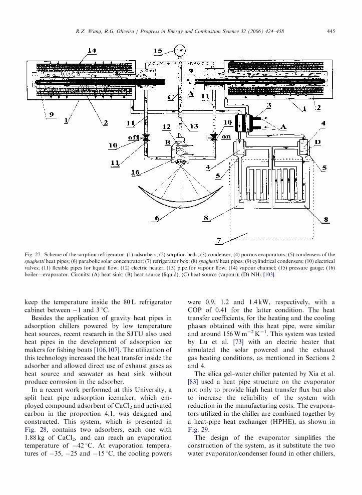
Heat pipes were used in the heat transfer fluid andrefrigerant circuits of the solar-electricity-poweredadsorption system studied by Vasiliev et al. [103].The heat sources supplied the necessary energy toevaporate the working fluid inside one of the heatpipe evaporators (16 in Fig. 27). When this fluidcondensed, it released heat to regenerate theadsorbents (2). The two phase heat transfer deviceof this system was constructed as a vapour dynamicthermosyphon, which had one small boiler eva-porator (16), two elongated cylindrical condensersinside the adsorber (9), a vapour chamber (16) with
two flexible pipes for liquid flow (11), and one pipefor vapour flow (13). There were also two valves(10) on the pipes for liquid flow that were used toregulate the feeding of water into the boiler.
A loop heat pipe was used to connect therefrigerant evaporator of the adsorption system(4 in Fig. 27) to the cold box. The condenser of theheat pipe (5) was placed on the outer surface of therefrigerant evaporator. The evaporation part ofthe multi-bent heat pipe was inserted along the wallsof the refrigerator. These two heat pipes arcs wereused as a second ammonia circuit, thermallyconnected with the first ammonia circuit (evapora-tors 4). When the temperature of the evaporatorsdecreased and became lower than the temperatureof the air inside the refrigerator, the ammonia insidethe heat pipe evaporated to condensate on the outersurface of the evaporator. The heat transfer betweenthe air inside the refrigerator and the cold heat pipepanel was performed by natural convection, andthis panel could provide 300W of cooling.
According to Vasiliev [99], vapour dynamicthermosyphon like the one employed in the systemdeveloped by Vasiliev et al. [104] has smallertemperature drops than conventional heat exchan-gers, which is favourable from the thermodynamicpoint of view.
Heat pipe heat exchangers were also utilized in arefrigerator/dryer system developed by Vasilievet al. [105]. The heat released from the adsorbersduring the generation phase was used to heat thedrying air, which could reach a temperature of60 1C. A loop heat pipe was used as evaporator to
ARTICLE IN PRESS
Fig. 27. Scheme of the sorption refrigerator: (1) adsorbers; (2) sorption beds; (3) condenser; (4) porous evaporators; (5) condensers of the
spaghetti heat pipes; (6) parabolic solar concentrator; (7) refrigerator box; (8) spaghetti heat pipes; (9) cylindrical condensers; (10) electrical
valves; (11) flexible pipes for liquid flow; (12) electric heater; (13) pipe for vapour flow; (14) vapour channel; (15) pressure gauge; (16)
boiler—evaporator. Circuits: (A) heat sink; (B) heat source (liquid); (C) heat source (vapour); (D) NH3 [103].
R.Z. Wang, R.G. Oliveira / Progress in Energy and Combustion Science 32 (2006) 424–458 445
keep the temperature inside the 80L refrigeratorcabinet between �1 and 3 1C.
Besides the application of gravity heat pipes inadsorption chillers powered by low temperatureheat sources, recent research in the SJTU also usedheat pipes in the development of adsorption icemakers for fishing boats [106,107]. The utilization ofthis technology increased the heat transfer inside theadsorber and allowed direct use of exhaust gases asheat source and seawater as heat sink withoutproduce corrosion in the adsorber.
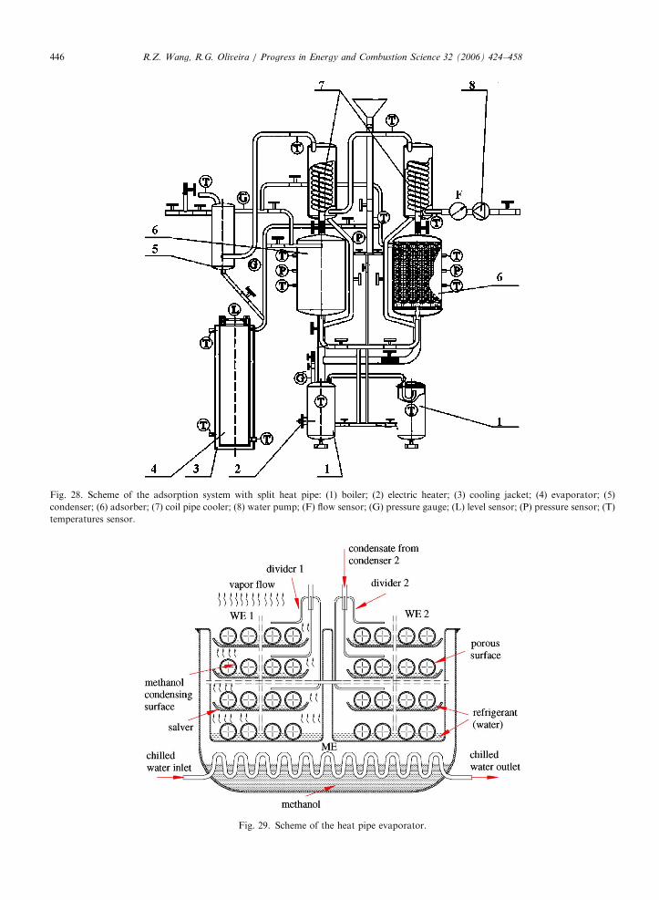
In a recent work performed at this University, asplit heat pipe adsorption icemaker, which em-ployed compound adsorbent of CaCl2 and activatedcarbon in the proportion 4:1, was designed andconstructed. This system, which is presented inFig. 28, contains two adsorbers, each one with1.88 kg of CaCl2, and can reach an evaporationtemperature of �42 1C. At evaporation tempera-tures of �35, �25 and �15 1C, the cooling powers
were 0.9, 1.2 and 1.4 kW, respectively, with aCOP of 0.41 for the latter condition. The heattransfer coefficients, for the heating and the coolingphases obtained with this heat pipe, were similarand around 156Wm�2K�1. This system was testedby Lu et al. [73] with an electric heater thatsimulated the solar powered and the exhaustgas heating conditions, as mentioned in Sections 2and 4.
The silica gel–water chiller patented by Xia et al.[83] used a heat pipe structure on the evaporatornot only to provide high heat transfer flux but alsoto increase the reliability of the system withreduction in the manufacturing costs. The evapora-tors utilized in the chiller are combined together bya heat-pipe heat exchanger (HPHE), as shown inFig. 29.
The design of the evaporator simplifies theconstruction of the system, as it substitute the twowater evaporator/condenser found in other chillers,
ARTICLE IN PRESS
Fig. 28. Scheme of the adsorption system with split heat pipe: (1) boiler; (2) electric heater; (3) cooling jacket; (4) evaporator; (5)
condenser; (6) adsorber; (7) coil pipe cooler; (8) water pump; (F) flow sensor; (G) pressure gauge; (L) level sensor; (P) pressure sensor; (T)
temperatures sensor.
Fig. 29. Scheme of the heat pipe evaporator.
R.Z. Wang, R.G. Oliveira / Progress in Energy and Combustion Science 32 (2006) 424–458446
ARTICLE IN PRESS
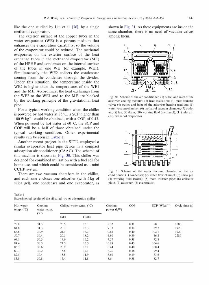
Fig. 30. Scheme of the air conditioner: (1) outlet and inlet of the
adsorber cooling medium; (2) heat insulation; (3) mass transfer
valve; (4) outlet and inlet of the adsorber heating medium; (5)
water vacuum chamber; (6) methanol vacuum chamber; (7) outlet
air; (8) fan; (9) drain; (10) working fluid (methanol); (11) inlet air;
(12) methanol evaporator.
Fig. 31. Scheme of the water vacuum chamber of the air
conditioner: (1) condenser; (2) water flow channel; (3) silica gel;
(4) working fluid (water); (5) mass transfer pipe; (6) collector
plate; (7) adsorber; (8) evaporator.
R.Z. Wang, R.G. Oliveira / Progress in Energy and Combustion Science 32 (2006) 424–458 447
like the one studied by Liu et al. [76], by a singlemethanol evaporator.
The exterior surface of the copper tubes in thewater evaporator (WE) is a porous medium thatenhances the evaporation capability, so the volumeof the evaporator could be reduced. The methanolevaporates on the exterior surface of the heatexchange tubes in the methanol evaporator (ME)of the HPHE and condenses on the internal surfaceof the tubes in one WE (for example, WE1).Simultaneously, the WE2 collects the condensatecoming from the condenser through the divider.Under this situation, the temperature inside theWE2 is higher than the temperatures of the WE1and the ME. Accordingly, the heat exchanges fromthe WE2 to the WE1 and to the ME are blockedby the working principle of the gravitational heatpipe.
For a typical working condition when the chilleris powered by hot water at 85 1C, a SCP higher than100Wkg�1 could be obtained, with a COP of 0.43.When powered by hot water at 60 1C, the SCP andCOP will be a half of those obtained under thetypical working condition. Other experimentalresults can be seen in Table 1.
Another recent project in the SJTU employed asimilar evaporator heat pipe device in a compactadsorption air conditioner (CAAC). The schema ofthis machine is shown in Fig. 30. This chiller wasdesigned for combined utilization with a fuel cell forhome use, and which could be considered as a miniCCHP system.
There are two vacuum chambers in the chiller,and each one encloses one adsorber (with 5 kg ofsilica gel), one condenser and one evaporator, as
Table 1
Experimental results of the silica gel–water adsorption chiller
Hot water
temp. (1C)
Cooling
water temp.
(1C)
Chilled water temp. (1C) C
p
Inlet Outlet
78.8 31.3 20.5 16
81.8 31.3 20.7 16.3
86.8 30.9 21.1 16.3 1
59.7 30.4 20.5 18.2
69.1 30.3 19.6 16.2
84.4 30.5 21.5 16.5 1
85.3 30.6 20.9 16.1 1
80.3 30.2 15.8 12.1
82.5 30.4 15.8 11.9
83.8 30.8 15.4 11.8
shown in Fig. 31. As these equipments are inside thesame chamber, there is no need of vacuum valvesamong them.
ooling
ower (kW)
COP SCP (Wkg�1) Cycle time (s)
8.32 0.31 80 1680
9.33 0.34 89.7 1920
0.62 0.40 102.1 1920
4.80 0.39 46.2 2280
7.57 0.38 72.8
0.88 0.43 104.6
0.44 0.40 100.4
8.26 0.38 79.4
8.69 0.39 83.6
8.6 0.38 82.7
ARTICLE IN PRESSR.Z. Wang, R.G. Oliveira / Progress in Energy and Combustion Science 32 (2006) 424–458448
When the adsorber is heated, the water is desorbedand vapour flows to the condenser. The condensedwater is moved by gravity to the evaporator, which islocated below the former device. During the adsorp-tion phase, as the adsorber is cooled, its pressuredecreases and water vapour from the evaporatorflows back to the adsorbers.
A methanol vacuum chamber, comprised by anevaporator and a condenser, surrounds the watervacuum chambers. The function of the methanolchamber is to transfer heat from the indoor air to theWE. The methanol condenser and the WE areintegrated into a single part called ‘‘separator’’. Whenthe indoor air flows through the ME, the methanolevaporates and condenses on the surface of the WE.The condensate returns to the ME by gravity.
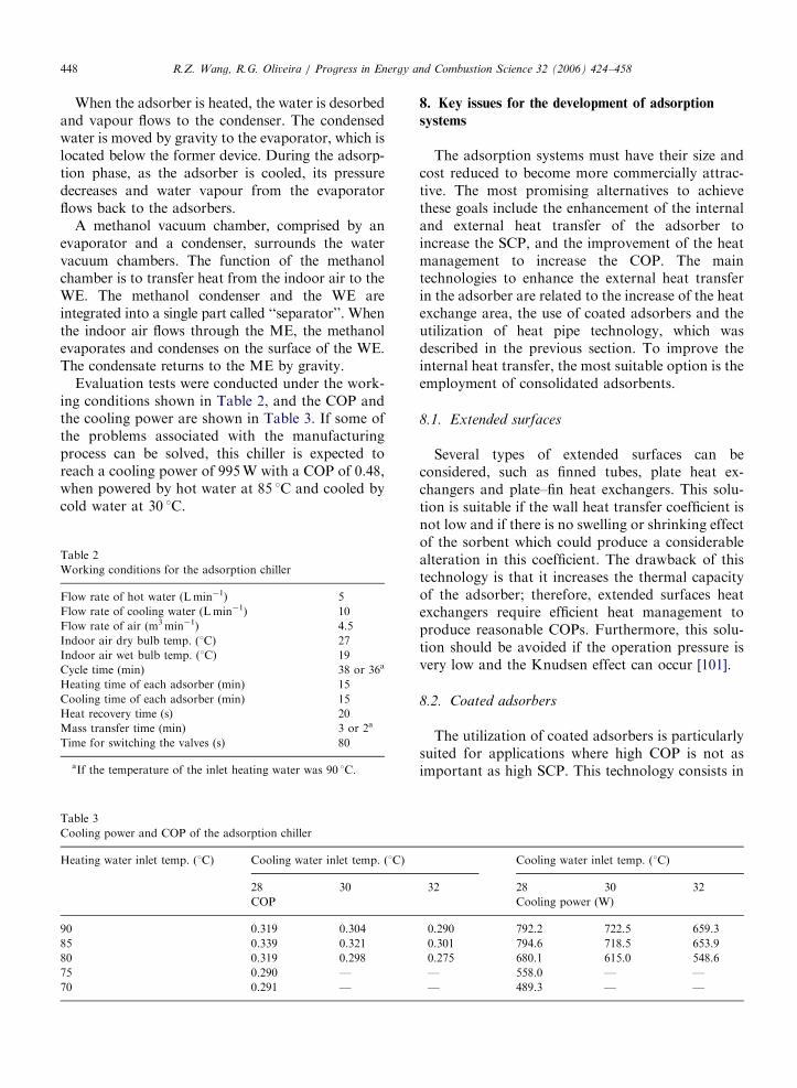
Evaluation tests were conducted under the work-ing conditions shown in Table 2, and the COP andthe cooling power are shown in Table 3. If some ofthe problems associated with the manufacturingprocess can be solved, this chiller is expected toreach a cooling power of 995W with a COP of 0.48,when powered by hot water at 85 1C and cooled bycold water at 30 1C.
Table 3
Cooling power and COP of the adsorption chiller
Heating water inlet temp. (1C) Cooling water inlet temp. (1C)
28 30
COP
90 0.319 0.304
85 0.339 0.321
80 0.319 0.298
75 0.290 —
70 0.291 —
Table 2
Working conditions for the adsorption chiller
Flow rate of hot water (Lmin�1) 5
Flow rate of cooling water (Lmin�1) 10
Flow rate of air (m3min�1) 4.5
Indoor air dry bulb temp. (1C) 27
Indoor air wet bulb temp. (1C) 19
Cycle time (min) 38 or 36a
Heating time of each adsorber (min) 15
Cooling time of each adsorber (min) 15
Heat recovery time (s) 20
Mass transfer time (min) 3 or 2a
Time for switching the valves (s) 80
aIf the temperature of the inlet heating water was 90 1C.
8. Key issues for the development of adsorption
systems
The adsorption systems must have their size andcost reduced to become more commercially attrac-tive. The most promising alternatives to achievethese goals include the enhancement of the internaland external heat transfer of the adsorber toincrease the SCP, and the improvement of the heatmanagement to increase the COP. The maintechnologies to enhance the external heat transferin the adsorber are related to the increase of the heatexchange area, the use of coated adsorbers and theutilization of heat pipe technology, which wasdescribed in the previous section. To improve theinternal heat transfer, the most suitable option is theemployment of consolidated adsorbents.
8.1. Extended surfaces
Several types of extended surfaces can beconsidered, such as finned tubes, plate heat ex-changers and plate–fin heat exchangers. This solu-tion is suitable if the wall heat transfer coefficient isnot low and if there is no swelling or shrinking effectof the sorbent which could produce a considerablealteration in this coefficient. The drawback of thistechnology is that it increases the thermal capacityof the adsorber; therefore, extended surfaces heatexchangers require efficient heat management toproduce reasonable COPs. Furthermore, this solu-tion should be avoided if the operation pressure isvery low and the Knudsen effect can occur [101].
8.2. Coated adsorbers
The utilization of coated adsorbers is particularlysuited for applications where high COP is not asimportant as high SCP. This technology consists in
Cooling water inlet temp. (1C)
32 28 30 32
Cooling power (W)
0.290 792.2 722.5 659.3
0.301 794.6 718.5 653.9
0.275 680.1 615.0 548.6
— 558.0 — —
— 489.3 — —
ARTICLE IN PRESSR.Z. Wang, R.G. Oliveira / Progress in Energy and Combustion Science 32 (2006) 424–458 449
the increase of the wall heat transfer coefficient bythe effective decrease of the contact thermalresistance between the heat exchange surface andthe adsorbent. Dunne [108] developed coated tubeswhere zeolite crystals monolayers grew on the tubemetal surfaces. The heating rate of this adsorber ishigher than 1500Wkg�1 of sorbent. Bou et al. [109]developed a coated heat exchanger where theadsorbent bed was inserted in an expanded graphiteplate. With this technique, the contact between theheat transfer fluid and the adsorbent is not as closeas in the previous coated tube, but the ratio betweenthe mass of adsorbent and the mass of inert materialis much higher, since the thickness of the adsorbentbed can reach a few millimetres.
The main disadvantage of using coated adsorberis the very high ratio between the inert mass and theadsorbent mass, which spoils the COP. In order toovercome this drawback, a very effective heatmanagement is required. Restuccia and Cacciola[35] compared by simulation the performances oftwo heat pumps in which one of them had anadsorber with coated surface and in the other one,the adsorber was filled with pelleted zeolite. Thecoated surface adsorber had a thin layer (1mm) ofzeolite, which was synthesized outside the tubes of atube and shell heat exchanger. The system withpelleted zeolite was from a previous study per-formed by Benthem et al. [29].
The system with coated tube had a cooling powerabout 3.6 times higher than that obtained with thesystem that employed pelleted zeolite. Due to theutilization of heat recovery process in both systems,the COP of the former was only 2% lower than theCOP of the latter.
8.3. Consolidated and composite adsorbents
Consolidated adsorbent with high thermal con-ductivity can be considered as the most promisingalternative to enhance the heat transfer within theadsorber. Poyelle et al. [36] used a consolidatedcomposite compound made from zeolite and ex-panded graphite with enhanced heat transferproperties in their experiments and achieved aSCP four times higher than that obtained usingzeolite pellets.
Guilleminot et al. [6] studied a consolidatedcomposite compound made from a mixture ofzeolite and metallic foam. The compound producedfrom zeolite and copper foam had a thermalconductivity of 8.0Wm�1K�1, which was 22 times
higher than that of consolidated zeolite. Theauthors stressed the importance of the metallicfoam material used in the compound, as the thermalconductivity obtained with the compound manu-factured from zeolite and nickel foam was only1.7Wm�1K�1.
Tamainot-Telto and Critoph [88] studied theperformance of a consolidated compound of acti-vated carbon and organic binder in an adsorptionsystem for ice making. They concluded that thesystem with the consolidated compound had a SCP90% higher than that of the system with granularcarbon.
A different approach was tested by Aidoun andTernan [17], Aidoun and Ternan [19], Dellero et al.[11], Dellero and Touzain [12], Vasiliev et al. [104]and Vasiliev et al. [105]. These authors used carbonfibers as adsorbent to obtain higher thermalconductivity and permeability in the sorbent bed.Vasiliev et al. [105] compared the performance of aheat pump using a carbon fiber called Busofit toanother heat pump which had this material im-pregnated with CaCl2. The cooling power of thelatter was 10% higher assuming that both systemshad an evaporation temperature of 20 1C. Accord-ing to Vasiliev et al. [104], the use of such a kind offiber with metallic salts promotes a thin filmdistribution of the salt through the whole volumeof the sorbent bed, which is beneficial to theadsorption process. These authors studied a heatpump with two adsorbers in which one was filledwith Busofit impregnated with BaCl2 and the otherwas filled with Busofit impregnated with NiCl2. Thissystem has a claimed coefficient of amplification(COA) of 1.43 with a temperature lift close to100 1C.
Dellero et al. [11] compared the adsorptionperformance of carbon fibers connected to metallicsalts by simple mixture, by impregnation and byintercalation. The results obtained by the latter twomethods were far superior to those obtained bysimple mixture. According to these authors, thecompounds made by impregnation or intercalationhave not only faster reaction rates, but also providecomplete reaction by avoiding the agglomerationphenomenon. The authors stressed that althoughboth methods present good adsorption perfor-mance, in the impregnation method, the salts startto adhere less to the fibers after few reactions whilein the intercalation method, the quantity of salt ishard controlled and the preparation time is verylong. The importance of the length of the fibers in
ARTICLE IN PRESSR.Z. Wang, R.G. Oliveira / Progress in Energy and Combustion Science 32 (2006) 424–458450
the heat transfer process inside the adsorbers wasconfirmed by the experiments performed by Delleroand Touzain [12]. These authors compared fibers 30and 3 cm long impregnated with MnCl2 and foundthat the reaction was completed within 15min withthe shorter fibers while it took about 60min with thelonger ones. The short fibers could remain posi-tioned in the radial direction, which was the samedirection of the heat transfer, while the long fiberstended to wind round the adsorber centre. Thedirection of the short fibers normal to the heattransfer could explain the fast reaction ratesobserved with this compound.
Aidoun and Ternan [17] impregnated carbonfibers with CoCl2 and obtained power densities, ina heat pump using ammonia as refrigerant, around280 kWm�3 that last for about 30min when thedecomposition pressure was set to 1000 kPa. Theauthors noted that when the sorbent reachedtemperatures close to 300 1C, the adsorption per-formance was deteriorated with consequent reduc-tion of the power density. In another work [19], thesame authors with similar sorbent obtained a powerdensity of about 235 kWm�3 during the synthesisphase, when the evaporator pressure was kept in therange between 700 and 950 kPa.
Fig. 32. Consolidated composite adsorbent made from CaCl2and activated carbon.
Fig. 33. Consolidated composite adsorbent from CaCl2 and expand
Wang et al. [21] developed a consolidatedcompound, which is shown in Fig. 32, made froma mixture of CaCl2 and activated carbon. Experi-ments performed by these authors showed that theutilization of this compound could lead to a coolingdensity 35% higher than that obtained by the use ofpowder CaCl2.
In recent work, Wang et al. [22] studied aconsolidated compound, made from CaCl2 andexpanded graphite. This compound presented athermal conductivity of more than 32 times higherthan that of powder CaCl2. An adsorption systemusing this compound could have a cooling densityof about 330MJm�3 at �10 1C, which is about45% higher than that obtained with powder CaCl2.Fig. 33 shows the consolidated compound beforeand after the adsorption of ammonia.
Eun et al. [13], studied the thermal and masstransfer properties of a compound made from silicagel and expanded graphite. Composite blocks with20–30% of graphite mass, and under a compressionpressure between 4 and 40MPa, showed a perme-ability of between 3 and 40� 10�12m2, and athermal conductivity of between 10 and20Wm�1K�1. These values of thermal conductivityare much higher than the 0.17Wm�1K�1 usuallyfound in granular silica gel packed bed.
Non-uniform reaction blocks, made from metallicsalts impregnated into an expanded graphite matrix,were manufactured by Lee et al. [24]. These blockswere designed to improve the heat and mass transferperformance of chemical heat pump adsorbers. Incontrast with other compounds that have uniformproperties, such as the bulk density and theexpanded graphite mass fraction, the studied blockswere prepared to increase the bulk density graduallyin the radius direction from 165 to 394 kgm�3. Theexperimental results showed that these blocks havemuch better heat transfer capability, since thetemperature gap between the inner and outer sides
graphite: (a) before adsorption and (b) after adsorption [22].
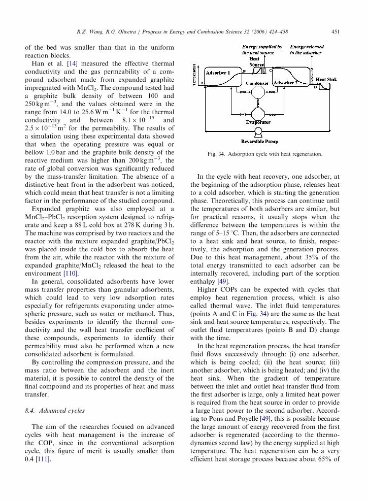
ARTICLE IN PRESS
Fig. 34. Adsorption cycle with heat regeneration.
R.Z. Wang, R.G. Oliveira / Progress in Energy and Combustion Science 32 (2006) 424–458 451
of the bed was smaller than that in the uniformreaction blocks.
Han et al. [14] measured the effective thermalconductivity and the gas permeability of a com-pound adsorbent made from expanded graphiteimpregnated with MnCl2. The compound tested hada graphite bulk density of between 100 and250 kgm�3, and the values obtained were in therange from 14.0 to 25.6Wm�1K�1 for the thermalconductivity and between 8.1� 10�15 and2.5� 10�13m2 for the permeability. The results ofa simulation using these experimental data showedthat when the operating pressure was equal orbellow 1.0 bar and the graphite bulk density of thereactive medium was higher than 200 kgm�3, therate of global conversion was significantly reducedby the mass-transfer limitation. The absence of adistinctive heat front in the adsorbent was noticed,which could mean that heat transfer is not a limitingfactor in the performance of the studied compound.
Expanded graphite was also employed at aMnCl2–PbCl2 resorption system designed to refrig-erate and keep a 88L cold box at 278K during 3 h.The machine was comprised by two reactors and thereactor with the mixture expanded graphite/PbCl2was placed inside the cold box to absorb the heatfrom the air, while the reactor with the mixture ofexpanded graphite/MnCl2 released the heat to theenvironment [110].
In general, consolidated adsorbents have lowermass transfer properties than granular adsorbents,which could lead to very low adsorption ratesespecially for refrigerants evaporating under atmo-spheric pressure, such as water or methanol. Thus,besides experiments to identify the thermal con-ductivity and the wall heat transfer coefficient ofthese compounds, experiments to identify theirpermeability must also be performed when a newconsolidated adsorbent is formulated.
By controlling the compression pressure, and themass ratio between the adsorbent and the inertmaterial, it is possible to control the density of thefinal compound and its properties of heat and masstransfer.
8.4. Advanced cycles
The aim of the researches focused on advancedcycles with heat management is the increase ofthe COP, since in the conventional adsorptioncycle, this figure of merit is usually smaller than0.4 [111].
In the cycle with heat recovery, one adsorber, atthe beginning of the adsorption phase, releases heatto a cold adsorber, which is starting the generationphase. Theoretically, this process can continue untilthe temperatures of both adsorbers are similar, butfor practical reasons, it usually stops when thedifference between the temperatures is within therange of 5–15 1C. Then, the adsorbers are connectedto a heat sink and heat source, to finish, respec-tively, the adsorption and the generation process.Due to this heat management, about 35% of thetotal energy transmitted to each adsorber can beinternally recovered, including part of the sorptionenthalpy [49].
Higher COPs can be expected with cycles thatemploy heat regeneration process, which is alsocalled thermal wave. The inlet fluid temperatures(points A and C in Fig. 34) are the same as the heatsink and heat source temperatures, respectively. Theoutlet fluid temperatures (points B and D) changewith the time.
In the heat regeneration process, the heat transferfluid flows successively through: (i) one adsorber,which is being cooled; (ii) the heat source; (iii)another adsorber, which is being heated; and (iv) theheat sink. When the gradient of temperaturebetween the inlet and outlet heat transfer fluid fromthe first adsorber is large, only a limited heat poweris required from the heat source in order to providea large heat power to the second adsorber. Accord-ing to Pons and Poyelle [49], this is possible becausethe large amount of energy recovered from the firstadsorber is regenerated (according to the thermo-dynamics second law) by the energy supplied at hightemperature. The heat regeneration can be a veryefficient heat storage process because about 65% of
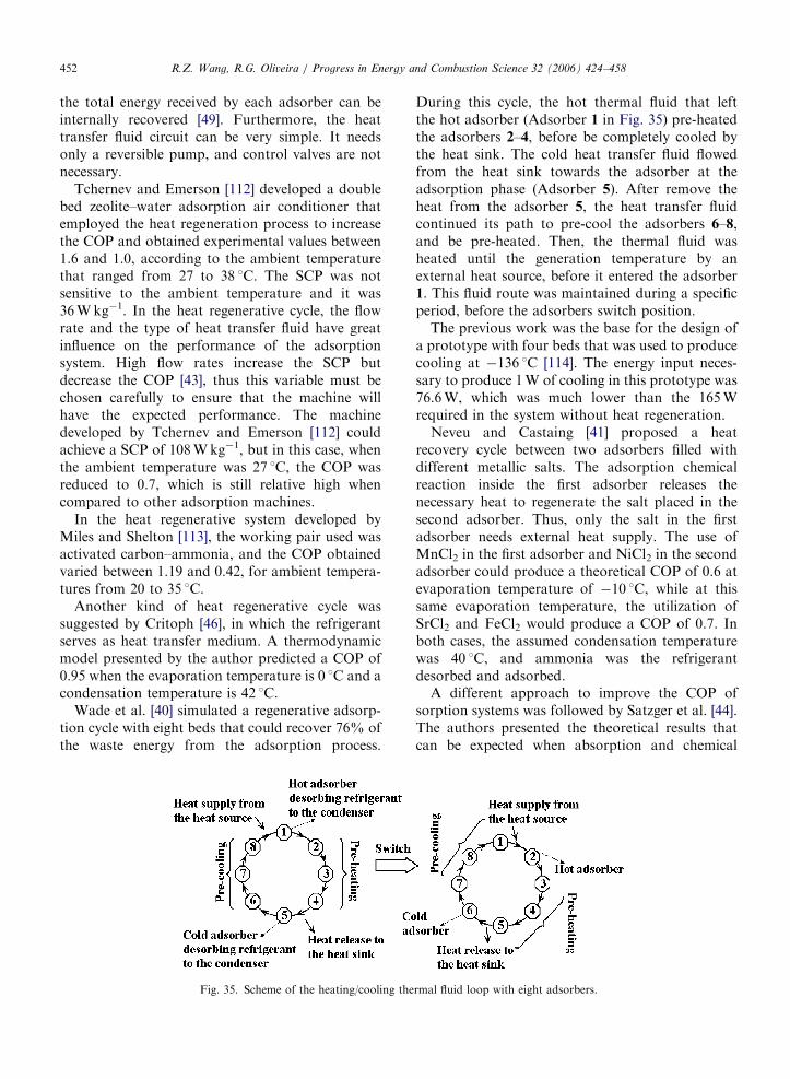
ARTICLE IN PRESSR.Z. Wang, R.G. Oliveira / Progress in Energy and Combustion Science 32 (2006) 424–458452
the total energy received by each adsorber can beinternally recovered [49]. Furthermore, the heattransfer fluid circuit can be very simple. It needsonly a reversible pump, and control valves are notnecessary.
Tchernev and Emerson [112] developed a doublebed zeolite–water adsorption air conditioner thatemployed the heat regeneration process to increasethe COP and obtained experimental values between1.6 and 1.0, according to the ambient temperaturethat ranged from 27 to 38 1C. The SCP was notsensitive to the ambient temperature and it was36Wkg�1. In the heat regenerative cycle, the flowrate and the type of heat transfer fluid have greatinfluence on the performance of the adsorptionsystem. High flow rates increase the SCP butdecrease the COP [43], thus this variable must bechosen carefully to ensure that the machine willhave the expected performance. The machinedeveloped by Tchernev and Emerson [112] couldachieve a SCP of 108Wkg�1, but in this case, whenthe ambient temperature was 27 1C, the COP wasreduced to 0.7, which is still relative high whencompared to other adsorption machines.
In the heat regenerative system developed byMiles and Shelton [113], the working pair used wasactivated carbon–ammonia, and the COP obtainedvaried between 1.19 and 0.42, for ambient tempera-tures from 20 to 35 1C.
Another kind of heat regenerative cycle wassuggested by Critoph [46], in which the refrigerantserves as heat transfer medium. A thermodynamicmodel presented by the author predicted a COP of0.95 when the evaporation temperature is 0 1C and acondensation temperature is 42 1C.
Wade et al. [40] simulated a regenerative adsorp-tion cycle with eight beds that could recover 76% ofthe waste energy from the adsorption process.
Fig. 35. Scheme of the heating/cooling the
During this cycle, the hot thermal fluid that leftthe hot adsorber (Adsorber 1 in Fig. 35) pre-heatedthe adsorbers 2–4, before be completely cooled bythe heat sink. The cold heat transfer fluid flowedfrom the heat sink towards the adsorber at theadsorption phase (Adsorber 5). After remove theheat from the adsorber 5, the heat transfer fluidcontinued its path to pre-cool the adsorbers 6–8,and be pre-heated. Then, the thermal fluid washeated until the generation temperature by anexternal heat source, before it entered the adsorber1. This fluid route was maintained during a specificperiod, before the adsorbers switch position.
The previous work was the base for the design ofa prototype with four beds that was used to producecooling at �136 1C [114]. The energy input neces-sary to produce 1W of cooling in this prototype was76.6W, which was much lower than the 165Wrequired in the system without heat regeneration.
Neveu and Castaing [41] proposed a heatrecovery cycle between two adsorbers filled withdifferent metallic salts. The adsorption chemicalreaction inside the first adsorber releases thenecessary heat to regenerate the salt placed in thesecond adsorber. Thus, only the salt in the firstadsorber needs external heat supply. The use ofMnCl2 in the first adsorber and NiCl2 in the secondadsorber could produce a theoretical COP of 0.6 atevaporation temperature of �10 1C, while at thissame evaporation temperature, the utilization ofSrCl2 and FeCl2 would produce a COP of 0.7. Inboth cases, the assumed condensation temperaturewas 40 1C, and ammonia was the refrigerantdesorbed and adsorbed.
A different approach to improve the COP ofsorption systems was followed by Satzger et al. [44].The authors presented the theoretical results thatcan be expected when absorption and chemical
rmal fluid loop with eight adsorbers.
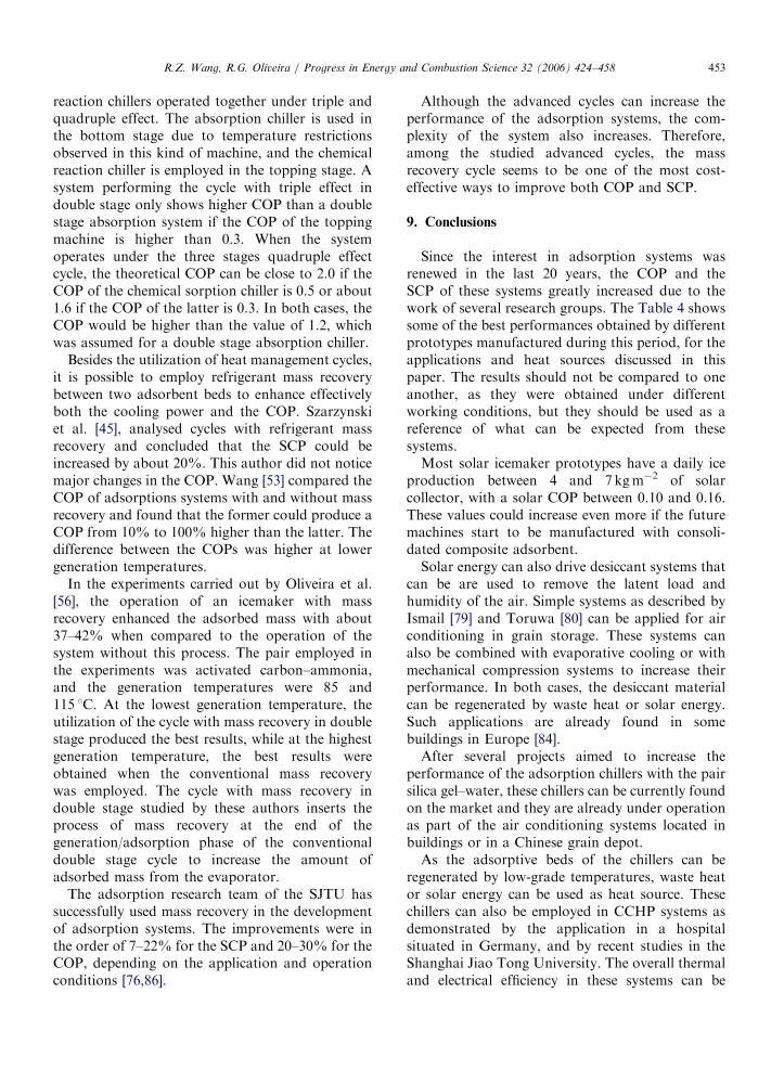
ARTICLE IN PRESSR.Z. Wang, R.G. Oliveira / Progress in Energy and Combustion Science 32 (2006) 424–458 453
reaction chillers operated together under triple andquadruple effect. The absorption chiller is used inthe bottom stage due to temperature restrictionsobserved in this kind of machine, and the chemicalreaction chiller is employed in the topping stage. Asystem performing the cycle with triple effect indouble stage only shows higher COP than a doublestage absorption system if the COP of the toppingmachine is higher than 0.3. When the systemoperates under the three stages quadruple effectcycle, the theoretical COP can be close to 2.0 if theCOP of the chemical sorption chiller is 0.5 or about1.6 if the COP of the latter is 0.3. In both cases, theCOP would be higher than the value of 1.2, whichwas assumed for a double stage absorption chiller.
Besides the utilization of heat management cycles,it is possible to employ refrigerant mass recoverybetween two adsorbent beds to enhance effectivelyboth the cooling power and the COP. Szarzynskiet al. [45], analysed cycles with refrigerant massrecovery and concluded that the SCP could beincreased by about 20%. This author did not noticemajor changes in the COP. Wang [53] compared theCOP of adsorptions systems with and without massrecovery and found that the former could produce aCOP from 10% to 100% higher than the latter. Thedifference between the COPs was higher at lowergeneration temperatures.
In the experiments carried out by Oliveira et al.[56], the operation of an icemaker with massrecovery enhanced the adsorbed mass with about37–42% when compared to the operation of thesystem without this process. The pair employed inthe experiments was activated carbon–ammonia,and the generation temperatures were 85 and115 1C. At the lowest generation temperature, theutilization of the cycle with mass recovery in doublestage produced the best results, while at the highestgeneration temperature, the best results wereobtained when the conventional mass recoverywas employed. The cycle with mass recovery indouble stage studied by these authors inserts theprocess of mass recovery at the end of thegeneration/adsorption phase of the conventionaldouble stage cycle to increase the amount ofadsorbed mass from the evaporator.
The adsorption research team of the SJTU hassuccessfully used mass recovery in the developmentof adsorption systems. The improvements were inthe order of 7–22% for the SCP and 20–30% for theCOP, depending on the application and operationconditions [76,86].
Although the advanced cycles can increase theperformance of the adsorption systems, the com-plexity of the system also increases. Therefore,among the studied advanced cycles, the massrecovery cycle seems to be one of the most cost-effective ways to improve both COP and SCP.
9. Conclusions
Since the interest in adsorption systems wasrenewed in the last 20 years, the COP and theSCP of these systems greatly increased due to thework of several research groups. The Table 4 showssome of the best performances obtained by differentprototypes manufactured during this period, for theapplications and heat sources discussed in thispaper. The results should not be compared to oneanother, as they were obtained under differentworking conditions, but they should be used as areference of what can be expected from thesesystems.
Most solar icemaker prototypes have a daily iceproduction between 4 and 7 kgm�2 of solarcollector, with a solar COP between 0.10 and 0.16.These values could increase even more if the futuremachines start to be manufactured with consoli-dated composite adsorbent.
Solar energy can also drive desiccant systems thatcan be are used to remove the latent load andhumidity of the air. Simple systems as described byIsmail [79] and Toruwa [80] can be applied for airconditioning in grain storage. These systems canalso be combined with evaporative cooling or withmechanical compression systems to increase theirperformance. In both cases, the desiccant materialcan be regenerated by waste heat or solar energy.Such applications are already found in somebuildings in Europe [84].
After several projects aimed to increase theperformance of the adsorption chillers with the pairsilica gel–water, these chillers can be currently foundon the market and they are already under operationas part of the air conditioning systems located inbuildings or in a Chinese grain depot.
As the adsorptive beds of the chillers can beregenerated by low-grade temperatures, waste heator solar energy can be used as heat source. Thesechillers can also be employed in CCHP systems asdemonstrated by the application in a hospitalsituated in Germany, and by recent studies in theShanghai Jiao Tong University. The overall thermaland electrical efficiency in these systems can be
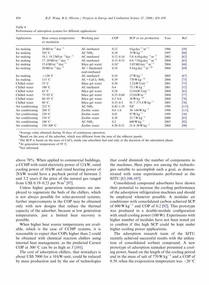
ARTICLE IN PRESS
Table 4
Performance of adsorption systems for different applications
Application Heat source temperature
or insolation
Working pair COP SCP or ice production Year Ref.
Ice making 20MJm�2 day�1 AC-methanol 0.12 6 kgday�1m�2 1986 [59]
Ice making 105 1C AC-NH3 0.10 35Wkg�1 1997 [88]
Ice making 18.1–19.2MJm�2 day�1 AC-methanol 0.12–0.14 5.0–6.0 kg day�1m�2 2002 [62]
Ice making 17–20MJm�2 day�1 AC-methanol 0.13–0.15 6.0–7.0 kg day�1m�2 2004 [63]
Ice making 15.4MJm�2 day�1 Silica gel–water 0.16a 2.05MJday�1m�2 2004 [68]
Ice making 20MJm�2 day�1 AC+blackened
steel-methanol
0.16 9.4 kgday�1m�2b 2004 [69]
Ice making o120 1C AC-methanol 0.18 27Wkg�1 2005 [87]
Ice making 115 1C AC+CaCl2–NH3 0.39 770Wkg�1c 2006 [73]
Chilled water 55 1C Silica gel–water 0.36 3.2 kWUnit�1 2001 [75]
Chilled water 100 1C AC-methanol 0.4 73.1Wkg�1 2001 [52]
Chilled water 65 1C Silica gel–water 0.28 12.0 kWUnit�1 2004 [83]
Chilled water 75–95 1C Silica gel–water 0.35–0.60 15.0 kWm�3 2004 [77]
Chilled water 80–95 1C Silica gel–water 0.3–0.6 20Wkg�1d 2004 [78]
Chilled water 80 1C Silica gel–water 0.33–0.5 91.7–171.8Wkg�1 2005 [76]
Air conditioning 232 1C AC-NH3 0.42–1.19 NIe 1996 [113]
Air conditioning 204 1C Zeolite–water 0.6–1.6 36–144Wkg�1 1998 [112]
Air conditioning 230 1C Zeolite–water 0.41 97Wkg�1 1999 [36]
Air conditioning 310 1C Zeolite–water 0.38 25.7Wkg�1 2000 [85]
Air conditioning 100 1C AC-NH3 0.2 600Wkg�1 2003 [92]
Air conditioning 230–300 1C Zeolite–water 0.20–0.21 21.4–30Wkg�1 2004 [90]
aAverage value obtained during 30 days of continuous operation.bBased on the area of the adsorber, which was different from the area of the reflector panels.cThe SCP is based on the mass of CaCl2 inside one adsorbent bed and only in the duration of the adsorption phase.dAt generation temperature of 95 1C.eNot informed.
R.Z. Wang, R.G. Oliveira / Progress in Energy and Combustion Science 32 (2006) 424–458454
above 70%. When applied to commercial buildings,a CCHP with rated electricity power of 12 kW, ratedcooling power of 10 kW and rated heating power of28 kW would have a payback period of between 2and 3.2 years if the price of the natural gas rangedfrom US$ 0.19–0.23 per Nm3 [97].
Unless higher generation temperatures are em-ployed to regenerate the beds of the chillers, whichis not always possible for solar-powered systems,further improvements in the COP may be obtainedonly with new designs that reduce the thermalcapacity of the adsorber, because at low generationtemperatures, just a limited heat recovery ispossible.
When higher heat source temperatures are avail-able, which is the case of CCHP systems, it isreasonable to expect that COPs higher than 2 couldbe obtained with chemical reaction chillers usinginternal heat management, as the predicted CarnotCOP at 300 1C can be as high as 3 [101].
The cost of adsorption chillers, that nowadays isabout US$ 7000 for a 10 kW-unit, could be reducedby mass production and by the use of technologies
that could diminish the number of components inthe machines. Heat pipes are among the technolo-gies suitable to accomplish such a goal, as demon-strated with some experiments performed at theSJTU [83,106,107].
Consolidated compound adsorbents have showntheir potential to increase the cooling performanceof the adsorption refrigeration machines and shouldbe employed whenever possible. A modular airconditioner with consolidated carbon achieved SCPof 600Wkg�1 and COP of 0.2 [92]. This prototypewas produced in a double-module configurationwith small cooling power (100W). Experiments withhigher number of modules have not been tested yetto confirm if this high SCP could be kept underhigher cooling power applications.
The adsorption research team of the SJTUrecently achieved successful results with the utiliza-tion of consolidated sorbent compound. A newprototype of adsorption icemaker presented a cool-ing power, based on the length of the cooling periodand in the mass of salt of 770Wkg�1 and a COP of0.39, when the evaporation temperature was �20 1C
ARTICLE IN PRESSR.Z. Wang, R.G. Oliveira / Progress in Energy and Combustion Science 32 (2006) 424–458 455
[73]. This prototype was designed to operate onfishing boats and uses split heat pipe technology toallow direct utilization of exhaust gases of dieselengines and seawater to, respectively, heat and coolthe adsorbers.
From the examples presented, it is possible toconsider that adsorption systems can be an alter-native to reduce the CO2 emissions and theelectricity demand when they are driven by wasteheat or solar energy. Although, for a broaderutilization, the researches should continue aimingfor improvements in heat transfer, reductions ofmanufacturing costs, and for the formulation ofnew adsorbent compounds with enhanced adsorp-tion capacity and improved heat and mass transferproperties.
Acknowledgements
This work was supported by the National ScienceFund for Distinguished Young Scholars of Chinaunder contract no. 50225621. It is also partlysupported by the National Key FundamentalResearch Program under contract no.G2000026309, the Teaching and Research AwardProgram for Outstanding Young Teachers in HigherEducation Institutions of MOE, China, and theShuguang Training Program of Shanghai EducationCommission under contract no. 02GG03.
The authors thank Elsevier for the kind permis-sion to use Figs. 2–7, 10, 12, 14, 16, 22–24 and 27,from the references 62, 63, 65, 68, 69, 71, 52, 76, 80,82, 90, 90, 92 and 103, respectively.
References
[1] Critoph RE. Performance limitations of adsorption cycles
for solar cooling. Sol Energy 1988;41(1):21–31.
[2] Luo L, Feidt M. Thermodynamics of adsorption cycles: a
theoretical study. Heat Transfer Eng 1992;13(4):19–31.
[3] Teng Y, Wang RZ, Wu JY. Study of the fundamentals of
adsorption systems. Appl Therm Eng 1997;17(4):327–38.
[4] Huber U, Stoeckli F, Houriet JP. A generalization of the
Dubinin–Radushkevich equation for the filing of hetero-
geneous micropore systems in strongly activated carbons.
J Colloid Interface Sci 1978;67(2):195–203.
[5] Passos FP. Etude des couples charbon actif/methanol et de
leur application a la refrigerations solaire [Ph.D.] Lau-
sanne: Ecole Polytechnique Federale de Lausanne; 1986.
101p.
[6] Guilleminot JJ, Choisier A, Chalfen JB, Nicolas S,
Reymoney JL. Heat transfer intensification in fixed bed
adsorbers. Heat Recov Syst CHP 1993;13(4):297–300.
[7] Mauran S, Prades P, L‘Haridon F. Heat and mass transfer
in consolidated reacting beds for thermochemical systems.
Heat Recov Syst CHP 1993;13(4):315–9.
[8] Critoph RE. Evaluation of alternative refrigerant-adsor-
bent pairs for refrigeration cycles. Appl Therm Eng
1996;16(11):891–900.
[9] Liu Z, Lu Y, Zhao J. Zeolite-active carbon compound
adsorbent and its use in adsorption solar cooling tube. Sol
Energy Mater Sol Cells 1998;52:45–53.
[10] Guilleminot JJ. From pellet to composite adsorbent bed:
evolutions of adsorber technologies. In: Proceedings of
fundamentals of adsorption (FOA6), France, 1998.
[11] Dellero T, Sarmeo D, Touzain Ph. A chemical heat pump
using carbon fibes as additive. Part I: enhancement of
thermal conduction. Appl Therm Eng 1999;19(9):991–1000.
[12] Dellero T, Touzain Ph. A chemical heat pump using carbon
fibes as additive. Part II: study of constraint parameters.
Appl Therm Eng 1999;19(9):1001–11.
[13] Eun TH, Song HK, Han JH, Lee KH, Kim JN.
Enhancement of heat and mass transfer in silica-expanded
graphite composite blocks for adsorption heat pumps: Part
I. Characterization of the composite blocks. Int J Refrig
2000;23(1):64–73.
[14] Han JH, Lee KH, Kim DH, Kim H. Transformation
analysis of thermochemical reactor based on thermophysi-
cal properties of graphite-MnCl2 complex. Ind Eng Chem
Res 2000;39(11):4127–39.
[15] Oliveira RG, TamainotTelto Z, Silveira Jr. V. Equilibrium
characterisation of carbon C119-ammonia and carbon
C119-dimethyl ether pairs and application in adsorption
refrigeration design. In: Proceedings of the XVI Brazilian
congress of mechanical engineering (COBEM 2001), Brazil,
2001.
[16] TamainotTelto Z, Critoph RE. Monolithic carbon for
sorption refrigeration and heat pump applications. Appl
Therm Eng 2001;21(1):37–52.
[17] Aidoun Z, Ternan M. Salt impregnated carbon fibres as the
reactive medium in a chemical heat pump: the NH3–CoCl2system. Appl Therm Eng 2002;22:1163–73.
[18] Freni A, Tokarev MM, Restuccia G, Okunev AG, Aristov
YI. Thermal conductivity of selective water sorbents under
the working conditions of a sorption chiller. Appl Therm
Eng 2002;22(14):1631–42.
[19] Aidoun Z, Ternan M. The synthesis reaction in a chemical
heat pump reactor filled with chloride salt impregnated
carbon fibres: the NH3–CoCl2 system. Appl Therm Eng
2002;22:1943–54.
[20] Li M, Huang HB, Wang RZ, Wang LL, Cai WD, Yang
WM. Experimental study on adsorbent of activated carbon
with refrigerant of methanol and ethanol for solar ice
maker. Renew Energy 2004;29(15):2235–44.
[21] Wang LW, Wang RZ, Wu JY, Wang K. Compound
adsorbent for adsorption ice maker on fishing boats. Int J
Refrig 2004;27:401–8.
[22] Wang K, Wu JY, Wang RZ, Wang LW. Composite
adsorbent of CaCl2 and expanded graphite for adsorp-
tion ice maker on fishing boats. Int J Refrig 2006;29(2):
199–210.
[23] Wang K, Wu JY, Wang RZ, Wang LW. Effective thermal
conductivity of expanded graphite-CaCl2 composite ad-
sorbent for chemical adsorption chillers. Energy Convers
Manage 2006;47(13–14):1902–12.
ARTICLE IN PRESSR.Z. Wang, R.G. Oliveira / Progress in Energy and Combustion Science 32 (2006) 424–458456
[24] Lee CH, Park SH, Choi SH, Kim YS, Kim SH.
Characteristics of non-uniform reaction blocks for chemi-
cal heat pump. Chem Eng Sci 2005;60(5):1401–9.
[25] Guilleminot JJ, Meunier F, Paklesa J. Heat and mass
transfer in a non-isothermal fixed bed solid adsorbent
reactor: a uniform pressure-non-uniform temperature case.
Int J Heat Mass Transfer 1987;30(8):1595–606.
[26] Cho SH, Kim JN. Modeling of a silica gel/water adsorp-
tion-cooling system. Energy 1992;17(9):829–39.
[27] Hermes HD, Pares JA, Velo E, Puigjaner L. Modelling and
sizing of gas-solid chilling machines. Comput Chem Eng
1995;19(Suppl.) S333–8.
[28] Sun LM, Ben AN, Meunier F. Numerical study on coupled
heat and mass transfers in an adsorber with external fluid
heating. Heat Recov Syst CHP 1995;15(1):19–29.
[29] Benthem GHWV, Cacciola G, Restuccia G. Regenerative
adsorption heat pumps: optimization of the design. Heat
Recov Syst CHP 1995;15(6):531–44.
[30] Hu EJ. Simulated results of a non-valve, daily-cycled, solar-
powered carbon/methanol refrigerator with a tubular solar
collector. Appl Therm Eng 1996;16(5):439–45.
[31] Lu HB, Mazet N, Spinner B. Modelling of gas–solid
reaction—coupling of heat and mass transfer with chemical
reaction. Chem Eng Sci 1996;51(15):3829–45.
[32] Poyelle F, Guilleminot JJ, Meunier F. Analytical study of a
gas-fired adsorptive air-conditioning system. ASHRAE
Trans 1996;102(1):1128–38.
[33] Stitou D, Goetz V, Spinner B. A new analytical model for
solid-gas thermochemical reactors based on thermophysical
properties of the reactive medium. Chem Eng Process
1997;51(15):3829–45.
[34] Chua HT, Ng KC, Malek A, Kashiwagi T, Akisawa A,
Saha BB. Modeling the performance of two-bed, silica
gel–water adsorption chillers. Int J Refrig 1999;22(3):
194–204.
[35] Restuccia G, Cacciola G. Performances of adsorption
systems for ambient heating and air conditioning. Int J
Refrig 1999;22(1):18–26.
[36] Poyelle F, Guilleminot JJ, Meunier F. Experimental tests
and predictive model of an adsorptive air conditioning unit.
Ind Eng Chem Res 1999;38(1):298–309.
[37] Leite APF, Daguenet M. Performance of a new solid
adsorption ice maker with solar energy regeneration. Energ
Convers Manage 2000;41(15):1625–47.
[38] Huang HJ, Wu GB, Yang J, Dai YC, Yuan WK, Lu HB.
Modeling of gas–solid chemisorption in chemical heat
pumps. Sep Purif Technol 2004;34:191–200.
[39] Douss N, Meunier F. Experimental study of cascading
adsorption cycles. Chem Eng Sci 1989;44:225–35.
[40] Wade L, Sywulka P, Hattar M, Alvarez J. High effici-
ency sorption refrigerator design. Adv Cryog Eng 1990;35:
1375–82.
[41] Neveu P, Castaing J. Solid–gas chemical heat pumps: field
of application and performance of the internal heat of
reaction recovery process. Heat Recov Syst CHP 1993;
13(3):233–51.
[42] Saha BB, Boelman EC, Kashiwagi T. Computational
analysis of an advanced adsorption refrigeration cycle.
Energy 1995;20(10):983–94.
[43] Pons M, Laurent D, Meunier F. Experimental temperature
fronts for adsorptive heat pump applications. Appl Therm
Eng 1996;16(5):395–404.
[44] Satzger P, Ziegler F, Stitou D, Spinner B, Alefeld G.
Advanced sorption chillers for gas cooling. ASHRAE
Trans 1996;102(1):1095–100.
[45] Szarzynski S, Feng Y, Pons M. Study of different internal
vapour transports for adsorption cycles with heat regen-
eration. Int J Refrig 1997;20(6):390–401.
[46] Critoph RE. Forced convection adsorption cycles. Appl
Therm Eng 1998;18(9–10):799–807.
[47] Wang RZ, Xu YX, Wu JY, Wang W. Experiments on heat
regenerative adsorption refrigerator and heat pump. Int J
Energy Res 1998;22:935–41.
[48] Wang RZ, Wu JY, Xu YX, Teng Y, Shi W. Experiment on
a continuous heat regenerative adsorption refrigerator
using spiral plate heat exchanger as adsorbers. Appl Therm
Eng 1998;18(1–2):13–23.
[49] Pons M, Poyelle F. Adsorptive machines with advanced
cycles for heat pumping or cooling applications. Int J
Refrig 1999;22(1):27–37.
[50] Qu TF, Wang RZ, Wang W. Study on heat and mass
recovery in adsorption refrigeration cycle. Appl Therm Eng
2001;21:439–52.
[51] Wang RZ. Adsorption refrigeration research in Shanghai Jiao
Tong University. Renew Sust Energy Rev 2001;5(1):1–37.
[52] Wang RZ, Wu JY, Xu YX, Wang W. Performance
researches and improvements on heat regenerative adsorp-
tion refrigerator and heat pump. Energy Convers Manage
2001;42(2):233–49.
[53] Wang RZ. Performance improvement of adsorption cool-
ing by heat and mass recovery operation. Int J Refrig
2001;24:602–11.
[54] Oliveira RG, Silveira Jr. V. The effects of operation and
design variables on the specific cooling power of an
advanced adsorption cycle for ice production powered by
low temperature heat source. In: Proceedings of the
international sorption heat pump conference (ISHPC
2002), China, 2002.
[55] Alam KCA, Akahira A, Hamamoto Y, Akisawa A,
Kashiwagi T. A four-bed mass recovery adsorption
refrigeration cycle driven by low temperature waste/renew-
able heat source. Renew Energy 2004;29:1461–75.
[56] Oliveira RG, Silveira Jr V, Wang RZ. Experimental study
of mass recovery adsorption cycles for ice making at
low generation temperature. Appl Therm Eng 2006;26:
303–11.
[57] Tchernev DI. Solar energy application of natural zeolites,
in natural zeolite: occurrence, properties and use. Oxford:
Pergamon Press; 1978 [479p].
[58] Guilleminot JJ, Meunier F. Etude experimentale d’une
glaciere solaire utilisant le cycle zeolithe 13X+eau. Rev
Gener Therm 1981;239:825–34.
[59] Pons M, Guilleminot JJ. Design of an experimental solar-
powered, solid-adsorption ice maker. J Sol Energy—Trans
ASME 1986;108(4):332–7.
[60] Critoph RE. Carbon–ammonia systems-revious experience,
current projects and challenges for the future. In: Proceed-
ings of the international sorption and heat pump con-
ference (ISHPC 2002), China, 2002.
[61] Critoph RE. Laboratory testing of an ammonia carbon
solar refrigerator. In: Proceedings of the solar world
congress (ISES), Hungary, 1993.
[62] Li M, Wang RZ, Xu YX, Wu JY, Dieng AO. Experimental
study on dynamic performance analysis of a flat-plate solar
ARTICLE IN PRESSR.Z. Wang, R.G. Oliveira / Progress in Energy and Combustion Science 32 (2006) 424–458 457
solid-adsorption refrigeration for ice maker. Renew Energy
2002;27(2):211–21.
[63] Li M, Sun CJ, Wang RZ, Ca WD. Development of no
valve solar ice maker. Appl Therm Eng 2004;24:865–72.
[64] Hu EJ. A study of thermal decomposition of methanol in
solar powered adsorption refrigeration systems. Sol Energy
1998;62(5):325–9.
[65] Buchter F, Dind P, Pons M. An experimental solar-
powered adsorptive refrigerator tested in Burkina-Faso. Int
J Refrig 2003;26(1):79–86.
[66] Boubakri A, Arsalane M, Yous B, Ali-Moussa L, Pons M,
Meunier F. Experimental study of adsorptive solar
powered ice makers in Agadir (Morocco)-1. Performance
in actual site. Renew Energy 1992;2(1):7–13.
[67] Boubakri A, Arsalane M, Yous B, Ali-Moussa L, Pons M,
Meunier F. Experimental study of adsorptive solar
powered ice makers in Agadir (Morocco)-2. Influences
of meteorological parameters. Renew Energy 1992;2(1):
15–21.
[68] Hildbrand C, Dind P, Pons M, Buchter F. A new solar
powered adsorption refrigerator with high performance.
Sol Energy 2004;77(3):311–8.
[69] Khattab NM. A novel solar-powered adsorption refrigera-
tion module. Appl Therm Eng 2004;24(17–18):2747–60.
[70] Oliveira RG. Avaliac- ao de um sistema de refrigerac- ao por
adsorc- ao para produc- ao de gelo, operando diferentes
tipos de ciclo com baixas temperaturas de gerac- ao
[Ph.D.] Campinas: State University of Campinas; 2004.
185p.
[71] Wang RZ, Li M, Xu YX, Wu JY. An energy efficient
hybrid system of solar powered water heater and adsorp-
tion ice maker. Sol Energy 2000;68(2):189–95.
[72] Wang RZ, Xu YX, Wu JY, Li M, Shou HB. Research on a
combined adsorption heating and cooling system. Appl
Therm Eng 2002;22(6):603–17.
[73] Lu ZS, Wang RZ, Wu JY, Chen CJ. Performance analysis
of an adsorption refrigerator using activated carbon in a
compound adsorbent. Carbon 2006;44:747–52.
[74] Grenier P, Guilleminot JJ, Meunier F, Pons M. Solar
powered solid adsorption cold store. J Sol Energy—Trans
ASME 1988;110(3):192–7.
[75] Saha BB, Akisawa A, Kashiwagi T. Solar/waste heat driven
two-stage adsorption chiller: the prototype. Renew Energy
2001;23(1):93–101.
[76] Liu YL, Wang RZ, Xia ZZ. Experimental study on a
continuous adsorption water chiller with novel design. Int J
Refrig 2005;28(2):218–30.
[77] Nunez T, Mittelbach W, Henning HM. Development of an
adsorption chiller and heat pump for domestic heating and
air-conditioning applications. In: Proceedings of the third
international conference on heat powered cycles (HPC
2004), Cyprus, 2004.
[78] Restuccia G, Freni A, Vasta S, Aristov Y. Selective water
sorbent for solid sorption chiller: experimental results and
modelling. Int J Refrig 2004;27(3):284–93.
[79] Ismail MZ, Angus DE, Thorpe GR. The performance of a
solar-regenerated open-cycle desiccant bed grain cooling
system. Sol Energy 1991;46(2):63–70.
[80] Thoruwa TFN, Grant AD, Smith JE, Johnstone CM. A
solar-regenerated desiccant dehumidifier for the aeration of
stored grain in the humid tropics. J Agric Eng Res 1998;
71(3):257–62.
[81] Henning HM, Erpenbeck T, Hindenburg C, Santamaria IS.
The potential of solar energy use in desiccant cooling
cycles. Int J Refrig 2001;24:220–9.
[82] Lu SM, Yan WJ. Development and experimental valida-
tion of a full-scale solar desiccant enhanced radiative
cooling. Renew Energy 1995;6(7):821–7.
[83] Xia ZZ, Wang RZ, Wu JY, Wang DC. New type of
effective adsorption chiller adopt separate heat pipe. China
patent 200410025398.0, 2004.
[84] The Climasol Project. In: http://www.raee.org/climasol
2005, last accessed 14/05/2005.
[85] Zhang LZ. Design and testing of an automobile waste heat
adsorption cooling system. Appl Therm Eng 2000;20:
103–14.
[86] Wang LW, Wu JY, Wang RZ, Xu YX, Wang SG.
Experimental study of a solidified activated carbon-
methanol adsorption ice maker. Appl Therm Eng 2003;
23(12):1453–62.
[87] Wang SG, Wang RZ. Recent developments of refrigeration
technology in fishing vessels. Renew Energy 2005;30(4):
589–600.
[88] TamainotTelto Z, Critoph RE. Adsorption refrigerator
using monolithic carbon-ammonia pair. Int J Refrig 1997;
20(2):146–55.
[89] Wang LW, Wang RZ, Wu JY, Wang K, Wang SG.
Adsorption ice makers for fishing boats driven by the
exhaust heat from diesel engine: choice of adsorption pair.
Energy Convers Manage 2004;45:2043–57.
[90] Lu YZ, Wang RZ, Jianzhou S, Xu YX, Wu JY. Practical
experiments on an adsorption air conditioner powered by
exhausted heat from a diesel locomotive. Appl Therm Eng
2004;24(1051–1059).
[91] Jiangzhou S, Wang RZ, Lu YZ, Xu YX, Wu JY.
Experimental investigations on adsorption air-conditioner
used in internal-combustion locomotive driver-cabin. Appl
Therm Eng 2002;22(10):1153–62.
[92] Tamainot-Telto Z, Critoph RE. Advanced solid sorption
air conditioning modules using monolithic carbon–ammo-
nia pair. Appl Therm Eng 2003;23(6):659–74.
[93] HIJC USA Inc. Waste heat adsorption chiller substitute
absorption. In: http://www.adsorptionchiller.bigstep.com
2005, last accessed 14/05/2005.
[94] Mycom—AdRef. In: http://www.mycomj.co.jp/ 2005, last
accessed 22/12/2005.
[95] Garland P, Hinrichs D, Cowie M. Integrating CHP into
commercial buildings. In: http://www.earthscan.co.uk/
news/article/mps/UAN/67/v/4/sp/332882698304342120264
2005, last accessed 14/05/2005.
[96] Rational supply of power, heat and cooling in the
malteser hospital St. Johannes in Kamenz. In: http://www.
malteser-krankenhaus-kamenz.de/englisch/index.htm 2005,
last accessed 14/05/2005.
[97] Wang RZ, Kong XQ, Wu JY, Huangfu Y, Wu DW.
Performance research of a micro CCHP system with
adsorption chiller. In: Proceedings of the international
sorption and heat pump conference (ISHPC 2005), USA,
2005.
[98] Maranthan A. Optimization of integrated microturbine and
absorption chiller systems in CHP for buildings applications
[Ph.D.] Maryland: University of Maryland; 2002. 130p.
[99] Vasiliev LL. Heat pipes in modern heat exchangers. Appl
Therm Eng 2005;25:1–19.
ARTICLE IN PRESSR.Z. Wang, R.G. Oliveira / Progress in Energy and Combustion Science 32 (2006) 424–458458
[100] Vasiliev LL, Mishkinis DA, Antukh AA, Vasiliev Jr LL.
Solar–gas solid sorption heat pump. Appl Therm Eng
2001;21:573–83.
[101] Meunier F. Solid sorption heat powered cycles for cooling
and heat pumping applications. Appl Therm Eng 1998;
18(9–10):715–29.
[102] Critoph RE. The use of thermosyphon heat pipes to
improve the performance of a carbon–ammonia adsorption
refrigerator. In: Proceedings of IV Minsk international
seminar—heat pipes, heat pumps, refrigerators, Belarus,
2000.
[103] Vasiliev LL, Mishkinis DA, Antukh AA, Vasiliev LL. A
solar and electrical solid sorption refrigerator. Int J Therm
Sci 1999;38(3):220–7.
[104] Vasiliev LL, Nikanpour D, Antukh A, Snelson K, Vasiliev
Jr. LL, Lebru A. Multisalt-carbon chemical cooler for
space applications. In: Proceedings of the international
sorption heat pump conference (ISHPC 1999), Germany,
1999.
[105] Vasiliev LL, Mishkinis DA, Vasiliev Jr. LL. Multi Effect
Complex compound/ammonia sorption machines In: Pro-
ceedings of the international sorption heat pump con-
ference (ISHPC 1996), Canada, 1996.
[106] Xia ZZ, Wang RZ, Wu JY, Wang LW. Compound
alternate heat pipe reactor powered by waste heat. China
patent 200410018291.3, 2004.
[107] Wang LW, Wang RZ, Wu JY. Separate heat pipe
adsorption ice maker for fishing boats. China patent
200310108924.5, 2003.
[108] Dunne S. Carousel heat exchanger for sorption cooling
process. USA patent 5.503.222, 1996.
[109] Bou P, Guilleminot JJ, Pons M. Composite actif a structure
feuilletee comprenant un agent actif sous forme de
granules. France patent 96.12762, 1996.
[110] Lepinasse E, Marion M, Goetz V. Cooling storage with
resorption process. Application to a box temperature
control. Appl Therm Eng 2001;21:1251–63.
[111] Meunier F, Kaushik SC, Neveu P, Poyelle F. A compara-
tive thermodynamic study of sorption systems: second law
analysis. Int J Refrig 1996;19(6):414–21.
[112] Tchernev DI, Emerson DT. High-efficiency regenerative
zeolite heat pump. ASHRAE Trans 1998;94(2):2024–32.
[113] Miles D, Shelton S. Design and testing of a solid-sorption
heat-pump system. Appl Therm Eng 1996;16:389–94.
[114] Wade L, Ryba E, Weston C, Alvarez J. Test performance of a
2W, 137K sorption refrigerator. Cryogenics 1992;32(2):122–6.