adsl transceivers dr. a. falahati bsc, c.eng, msc, mic, phd, miee dept. of electrical &...
TRANSCRIPT
ADSL TransceiversADSL Transceivers
Dr. A. Falahati BSc, C.Eng, MSc, MIC, PhD, MIEE
Dept. of Electrical & Electrical Eng.Iran University of Sceince & Technology
18 - 2
OutlineOutline• Introduction
• Modulation
• Asymmetric DSL (ADSL) Transceivers– Multicarrier Modulation in ADSL
– ADSL Transceiver Block Diagram
• Combating Inter-symbol Interference– Single-carrier communication systems
– Multicarrier communication systems
• Equalization in ADSL Transceivers– Time-Domain Equalization
– Frequency-Domain Equalization
• Conclusion
18 - 3
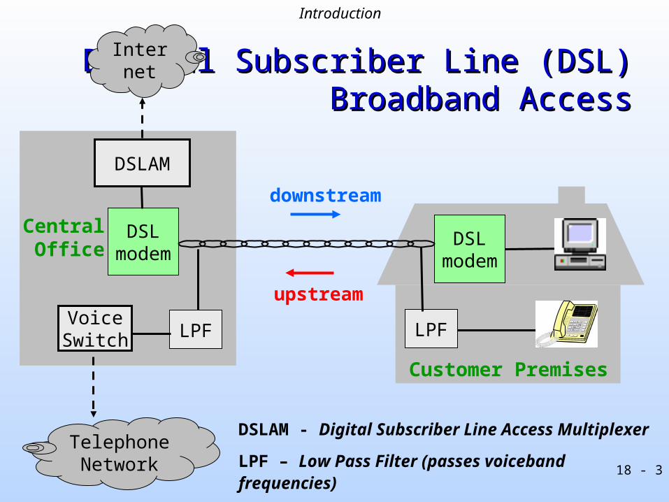
Digital Subscriber Line (DSL)Digital Subscriber Line (DSL) Broadband Access Broadband Access
Customer Premises
downstream
upstreamVoiceSwitch
Central Office
DSLAM
DSL modem
DSL modem
LPFLPF
Internet
DSLAM - Digital Subscriber Line Access Multiplexer
LPF – Low Pass Filter (passes voiceband frequencies)
Telephone Network
Introduction
18 - 4
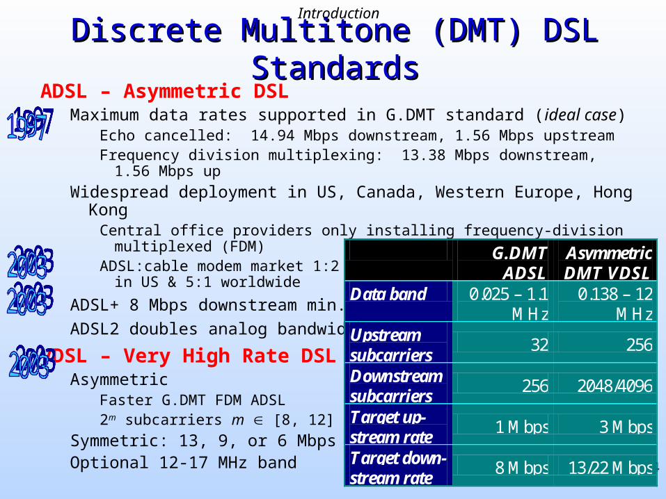
Discrete Multitone (DMT) DSL StandardsDiscrete Multitone (DMT) DSL StandardsADSL – Asymmetric DSL
Maximum data rates supported in G.DMT standard (ideal case)Echo cancelled: 14.94 Mbps downstream, 1.56 Mbps upstreamFrequency division multiplexing: 13.38 Mbps downstream, 1.56 Mbps up
Widespread deployment in US, Canada, Western Europe, Hong KongCentral office providers only installing frequency-division multiplexed (FDM) ADSL:cable modem market 1:2
in US & 5:1 worldwide
ADSL+ 8 Mbps downstream min.
ADSL2 doubles analog bandwidth
VDSL – Very High Rate DSLAsymmetric
Faster G.DMT FDM ADSL2m subcarriers m [8, 12]
Symmetric: 13, 9, or 6 MbpsOptional 12-17 MHz band
G.DMT ADSL
Asymmetric DMT VDSL
Data band 0.025 – 1.1 MHz
0.138 – 12 MHz
Upstream subcarriers
32 256
Downstream subcarriers
256 2048/4096
Target up- stream rate
1 Mbps 3 Mbps
Target down- stream rate
8 Mbps 13/22 Mbps
Introduction
18 - 5
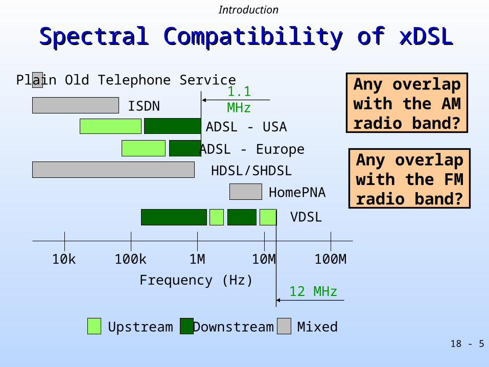
Spectral Compatibility of xDSLSpectral Compatibility of xDSL
10k 100k 1M 10M 100M
Plain Old Telephone Service
ISDN
ADSL - USA
ADSL - Europe
HDSL/SHDSL
HomePNA
VDSL
Upstream Downstream Mixed
Frequency (Hz)
1.1 MHz
12 MHz
Any overlap with the AM radio band?
Any overlap with the FM radio band?
Introduction
18 - 6
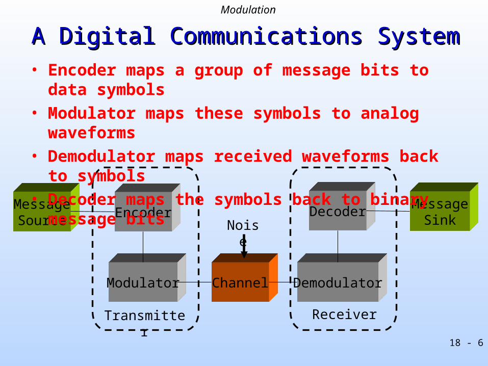
MessageSource
Modulator
Encoder
Channel Demodulator
DecoderMessage
SinkNoise
Transmitter Receiver
A Digital Communications SystemA Digital Communications System• Encoder maps a group of message bits to data symbols
• Modulator maps these symbols to analog waveforms
• Demodulator maps received waveforms back to symbols
• Decoder maps the symbols back to binary message bits
Modulation
18 - 7
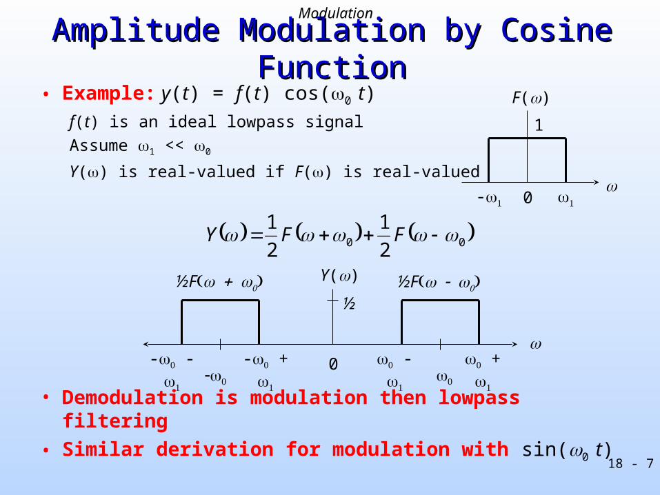
Amplitude Modulation by Cosine FunctionAmplitude Modulation by Cosine Function
• Example: y(t) = f(t) cos(0 t)
f(t) is an ideal lowpass signal
Assume 1 << 0
Y() is real-valued if F() is real-valued
• Demodulation is modulation then lowpass filtering
• Similar derivation for modulation with sin(0 t)
0
1
-
F()
0
½
- - - +
- +
½F½F
00 2
1
2
1 FFY
Y()
Modulation

18 - 8
Amplitude Modulation by Sine FunctionAmplitude Modulation by Sine Function
• Example: y(t) = f(t) sin(0 t)
f(t) is an ideal lowpass signal
Assume 1 << 0
Y() is imaginary-valued ifF() is real-valued
• Demodulation is modulation then lowpass filtering
0
1
-
F()
j ½
- - - +
- +
-j ½Fj ½F
-j ½
00 22 F
jF
jY
Y()
Modulation

18 - 9
– Single carrier
– Single signal, occupying entire available bandwidth
– Symbol rate is bandwidth of signal being centered on carrier frequency
Quadrature Amplitude Modulation (QAM)Quadrature Amplitude Modulation (QAM)
Bits Constellation encoder Bandpass
Lowpassfilter
Lowpassfilter
I
Q
Transmit
cos(2fc t)
sin(2fc t)
-
Modulator
I
Q iX
00110
frequency
channel
mag
nitu
de
fc
Modulation
18 - 10
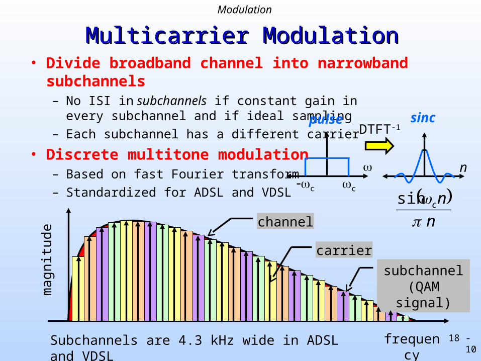
Multicarrier ModulationMulticarrier Modulation• Divide broadband channel into narrowband subchannels
– No ISI in subchannels if constant gain inevery subchannel and if ideal sampling
– Each subchannel has a different carrier
• Discrete multitone modulation– Based on fast Fourier transform
– Standardized for ADSL and VDSL
subchannel(QAM signal)
frequency
ma
gn
itude
carrier
DTFT-1pulse sinc
ncc
n
nc
sin
channel
Subchannels are 4.3 kHz wide in ADSL and VDSL
Modulation

18 - 11
Multicarrier Modulation by Inverse FFTMulticarrier Modulation by Inverse FFT
2/NX
x
tfje 12
1X
x
tfje 22
x
tfj Ne 2/2
+
g(t)
2X g(t)
g(t)
x
nN
je
12
1X
x
nN
je
22
x
nN
Nj
e2/
2
+2X
2/NX
Discretetime
g(t) : pulse shaping filter Xi : ith symbol from encoder
I
QiX
Modulation
18 - 12
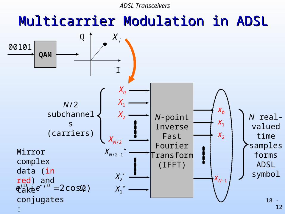
Multicarrier Modulation in ADSLMulticarrier Modulation in ADSL
N-pointInverse
FastFourier
Transform(IFFT)
X1
X2
X1*
x0
x1
x2
xN-1X2
*
XN/2
XN/2-1*
X0
N real-valuedtime
samplesformsADSL
symbol
N/2 subchannels
(carriers)
QAM00101
I
QiX
Mirror complex data (in red) andtake conjugates:
)cos( 2 jj ee
ADSL Transceivers
18 - 13
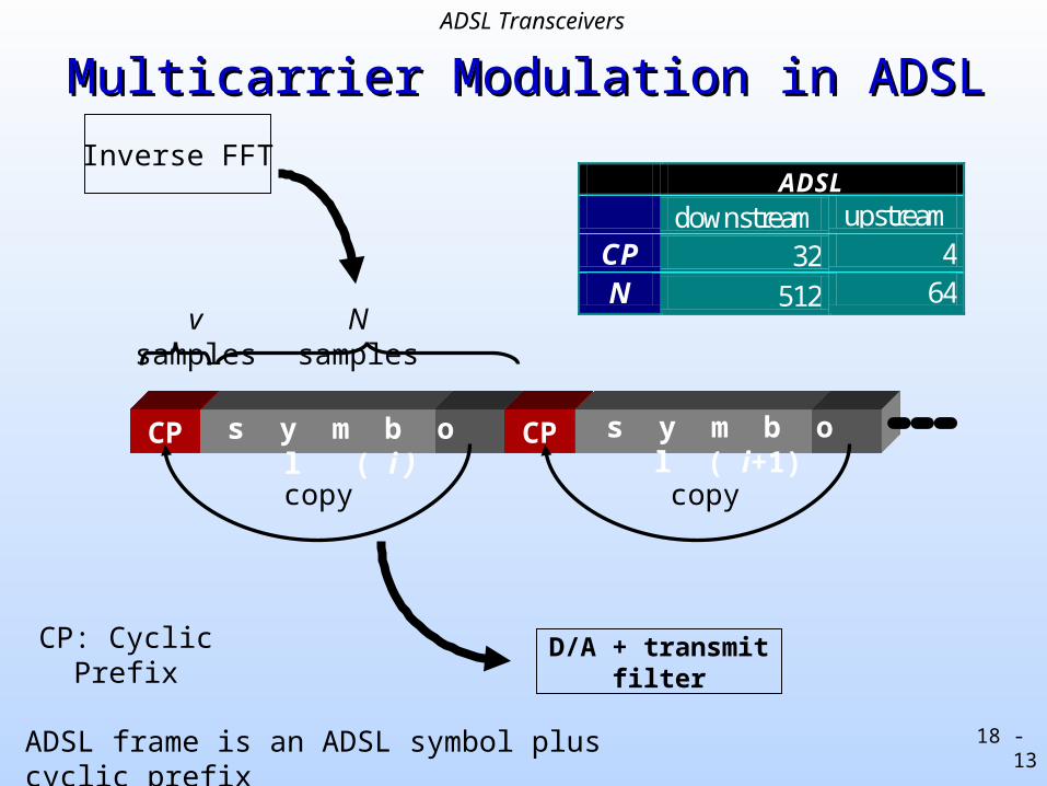
Multicarrier Modulation in ADSLMulticarrier Modulation in ADSL
CP: Cyclic Prefix
N samplesv samples
CP CPs y m b o l ( i ) s y m b o l ( i+1)
copy copy
D/A + transmit filter
ADSL downstream upstream
CP 32 4 N 512 64
Inverse FFT
ADSL frame is an ADSL symbol plus cyclic prefix
ADSL Transceivers
18 - 14
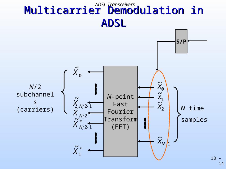
Multicarrier Demodulation in ADSLMulticarrier Demodulation in ADSL
N-pointFast
FourierTransform
(FFT)
N time
samples
N/2 subchannels
(carriers)
S/P
*1
~X
*12
~NX
2
~NX
12
~NX
0
~X
0~x
1~x
2~x
1~
Nx
ADSL Transceivers
18 - 15
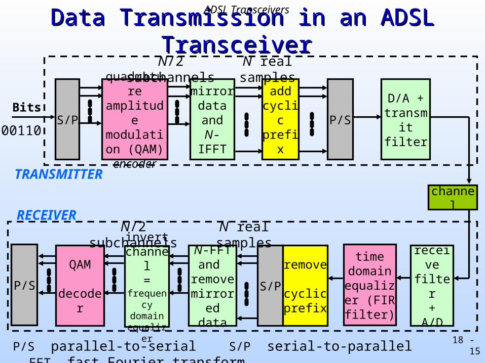
P/S QAM decoder
invert channel
=frequency
domainequalizer
S/P
quadrature amplitude
modulation (QAM) encoder
mirrordataand
N-IFFT
add cyclic prefix
P/SD/A +
transmit filter
N-FFTand
removemirrored
data
S/Premove
cyclic prefix
TRANSMITTER
RECEIVER
N/2 subchannels N real samples
N real samplesN/2 subchannels
time domain
equalizer (FIR filter)
receive filter
+A/D
channel
Data Transmission in an ADSL TransceiverData Transmission in an ADSL Transceiver
Bits
00110
P/S parallel-to-serial S/P serial-to-parallel FFT fast Fourier transform
ADSL Transceivers
18 - 16
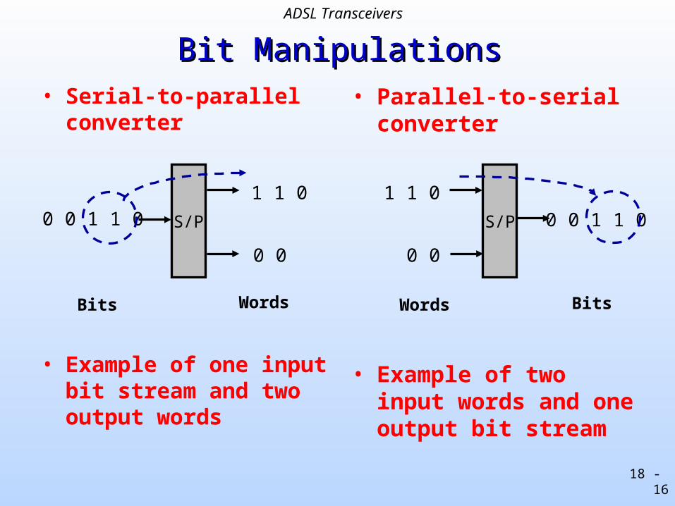
Bit ManipulationsBit Manipulations• Serial-to-parallel
converter
• Example of one input bit stream and two output words
• Parallel-to-serialconverter
• Example of two input words and one output bit stream
S/P
Bits
0 0 1 1 01 1 0
0 0
Words
S/P
Words
0 0 1 1 0
1 1 0
0 0
Bits
ADSL Transceivers
18 - 17
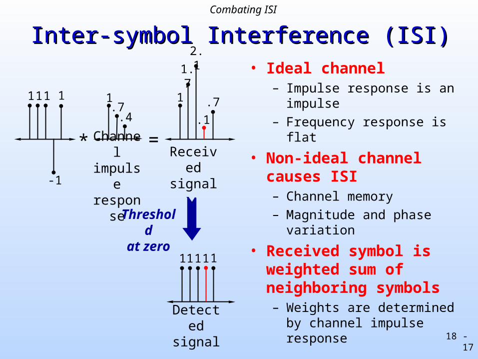
Inter-symbol Interference (ISI)Inter-symbol Interference (ISI)• Ideal channel
– Impulse response is an impulse
– Frequency response is flat
• Non-ideal channelcauses ISI– Channel memory
– Magnitude and phase variation
• Received symbol is weighted sum of neighboring symbols– Weights are determined by
channel impulse response
1 1 1
-1
1.7
.4 .1
1
1.7
2.1
11 1 1
Channelimpulseresponse
Received signal
Thresholdat zero
Detected signal
* =
1 .7
1
Combating ISI
18 - 18
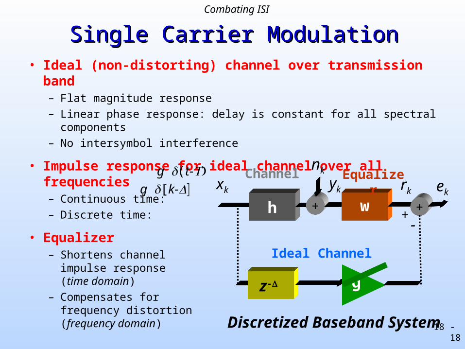
Single Carrier ModulationSingle Carrier Modulation• Ideal (non-distorting) channel over transmission band
– Flat magnitude response
– Linear phase response: delay is constant for all spectral components
– No intersymbol interference
• Impulse response for ideal channel over all frequencies– Continuous time:
– Discrete time:
• Equalizer– Shortens channel
impulse response(time domain)
– Compensates forfrequency distortion(frequency domain)
g[k-
Discretized Baseband System
g(t-
z-
h + w-
xk yk ekrk
nk
+
EqualizerChannel
g
Ideal Channel
+
Combating ISI
18 - 19
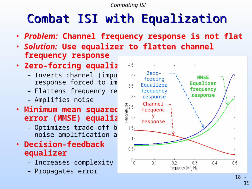
Combat ISI with EqualizationCombat ISI with Equalization• Problem: Channel frequency response is not flat• Solution: Use equalizer to flatten channel frequency response• Zero-forcing equalizer
– Inverts channel (impulseresponse forced to impulse)
– Flattens frequency response– Amplifies noise
• Minimum mean squarederror (MMSE) equalizer– Optimizes trade-off between
noise amplification and ISI
• Decision-feedbackequalizer– Increases complexity– Propagates error
Channel frequency response
Zero-forcing Equalizer frequency response
MMSEEqualizer frequency response
Combating ISI
18 - 20
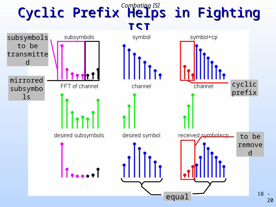
Cyclic Prefix Helps in Fighting ISICyclic Prefix Helps in Fighting ISI
subsymbols to be transmitted
mirrored subsymbols
cyclic prefix
equal
to be removed
Combating ISI

18 - 21
Cyclic Prefix Helps in Fighting ISICyclic Prefix Helps in Fighting ISI
• Provide guard time between successive symbols– No ISI if channel length is shorter than +1 samples
• Choose guard time samples to be a copy of the beginning of the symbol – cyclic prefix– Cyclic prefix converts linear convolution into circular convolution
– Need circular convolution so that
symbol channel FFT(symbol) x FFT(channel)
– Then division by the FFT(channel) can undo channel distortion
N samplesv samples
CP CPs y m b o l ( i ) s y m b o l ( i+1)
copy copy
Combating ISI
18 - 22
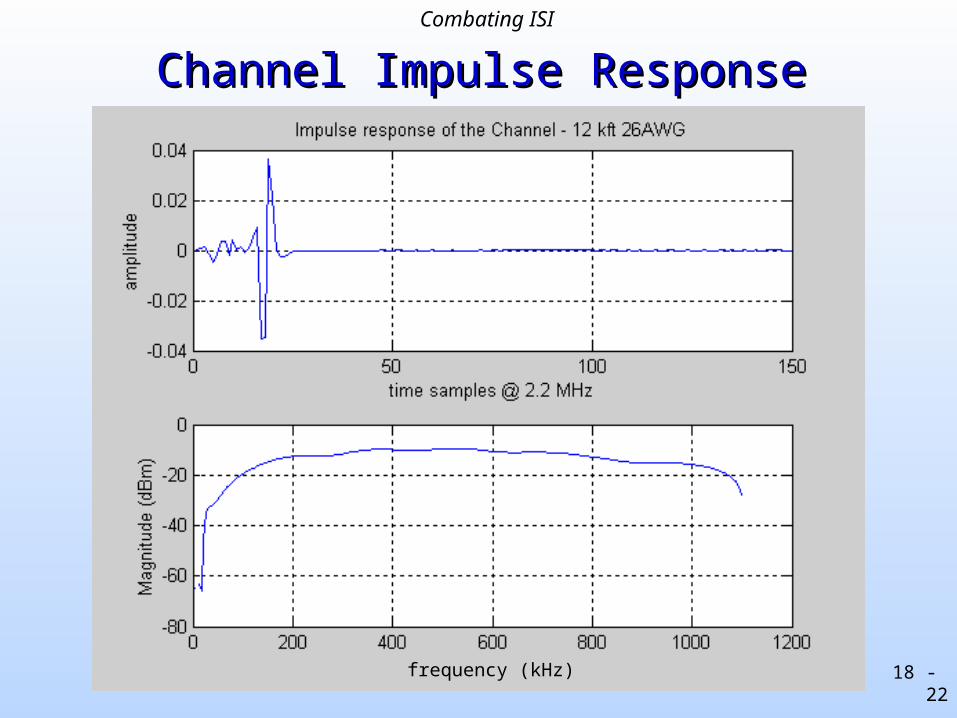
Channel Impulse ResponseChannel Impulse Response
frequency (kHz)
Combating ISI
18 - 23
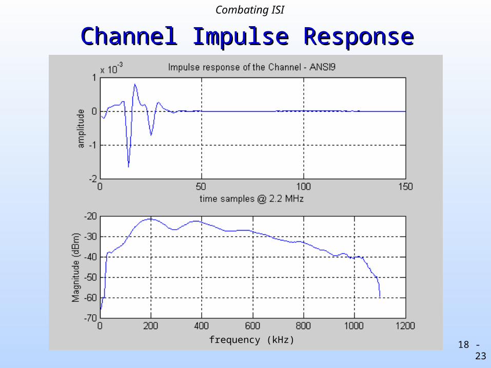
Channel Impulse ResponseChannel Impulse Response
frequency (kHz)
Combating ISI
18 - 24
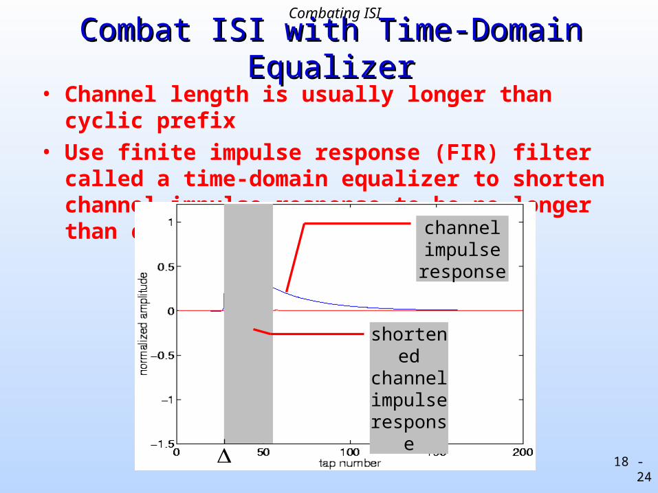
Combat ISI with Time-Domain EqualizerCombat ISI with Time-Domain Equalizer• Channel length is usually longer than cyclic prefix
• Use finite impulse response (FIR) filter called a time-domain equalizer to shorten channel impulse response to be no longer than cyclic prefix length
channel impulse response
shortened channel impulse response
Combating ISI
18 - 25
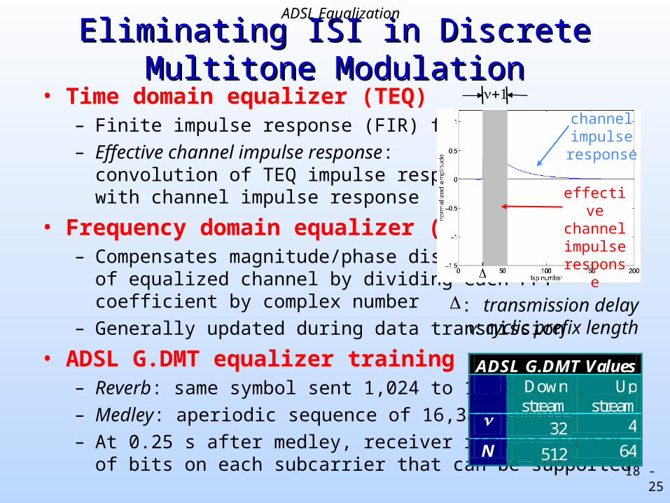
Eliminating ISI in Discrete Multitone Eliminating ISI in Discrete Multitone ModulationModulation
• Time domain equalizer (TEQ)– Finite impulse response (FIR) filter
– Effective channel impulse response:convolution of TEQ impulse responsewith channel impulse response
• Frequency domain equalizer (FEQ)– Compensates magnitude/phase distortion
of equalized channel by dividing each FFTcoefficient by complex number
– Generally updated during data transmission
• ADSL G.DMT equalizer training– Reverb: same symbol sent 1,024 to 1,536 times
– Medley: aperiodic sequence of 16,384 symbols
– At 0.25 s after medley, receiver returns numberof bits on each subcarrier that can be supported
ADSL G.DMT Values Down
stream Up
stream 32 4
N 512 64
channel impulse response
effective channel impulse response
: transmission delay: cyclic prefix length
ADSL Equalization
18 - 26
Time-Domain Equalizer DesignTime-Domain Equalizer Design• Minimizing mean squared error
– Minimize mean squared error (MMSE) method [Chow & Cioffi, 1992]
– Geometric SNR method [Al-Dhahir & Cioffi, 1996]
• Minimizing energy outside of shortened channel response– Maximum Shortening SNR method [Melsa, Younce & Rohrs, 1996]
– Minimum ISI method [Arslan, Evans & Kiaei, 2000]
• Maximizing achievable bit rate– Maximum bit rate method [Arslan, Evans, Kiaei, 2000]
– Maximum data rate method [Milosevic, Pessoa, Evans, Baldick, 2002]
– Bit rate maximization [Vanblue, Ysebaert, Cuypers, Moonen & Van Acker, 2003]
• Other equalizer architectures– Dual-path (DP) design uses two TEQs [Ming, Redfern & Evans, 2002]
– TEQ filter bank design [Milosevic, Pessoa, Evans, Baldick, 2002]
– Per tone equalization [Acker, Leus, Moonen, van der Wiel, Pollet, 2001]
ADSL Equalization
18 - 27
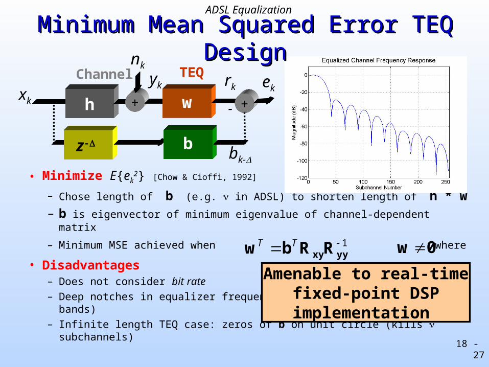
• Minimize E{ek2} [Chow & Cioffi, 1992]
– Chose length of b (e.g. in ADSL) to shorten length of h * w– b is eigenvector of minimum eigenvalue of channel-dependent matrix
– Minimum MSE achieved when where
• Disadvantages– Does not consider bit rate
– Deep notches in equalizer frequency response (zeros out low SNR bands)
– Infinite length TEQ case: zeros of b on unit circle (kills subchannels)
Minimum Mean Squared Error TEQ DesignMinimum Mean Squared Error TEQ Design
1 yyxyRRbw TT 0w
z-
h + w
b
-xk
yk ekrk
nk
+
bk-
TEQChannel
Amenable to real-time fixed-point DSP implementation
ADSL Equalization
18 - 28
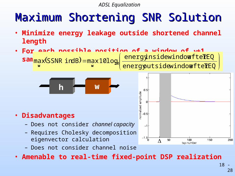
Maximum Shortening SNR SolutionMaximum Shortening SNR Solution• Minimize energy leakage outside shortened channel length
• For each possible position of a window of +1 samples,
• Disadvantages– Does not consider channel capacity
– Requires Cholesky decomposition andeigenvector calculation
– Does not consider channel noise
• Amenable to real-time fixed-point DSP realization
TEQafter windowoutsideenergy
TEQafter windowinsideenergy log10 maxdBin SSNRmax 10
ww
h w
ADSL Equalization
18 - 29
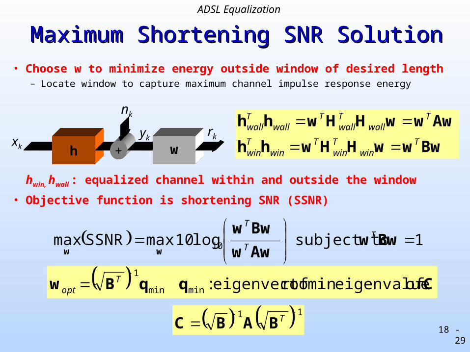
Maximum Shortening SNR SolutionMaximum Shortening SNR Solution
hwin, hwall : equalized channel within and outside the window
• Objective function is shortening SNR (SSNR)
h + wxk
ykrk
nk
BwwwHHwhh
AwwwHHwhhT
winTwin
Twin
Twin
Twall
Twall
Twall
Twall
• Choose w to minimize energy outside window of desired length– Locate window to capture maximum channel impulse response energy
1 subject to log10 maxSSNRmax 10
Bww
Aww
Bwwww
TT
T
CqqBw of eigenvalue min ofr eigenvecto : minmin
1 T
opt
11 TBABC
ADSL Equalization
18 - 30
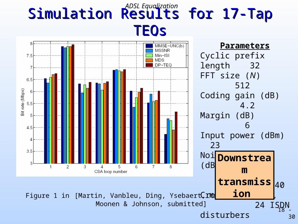
Simulation Results for 17-Tap TEQsSimulation Results for 17-Tap TEQs
ParametersCyclic prefix length 32FFT size (N) 512Coding gain (dB) 4.2Margin (dB) 6Input power (dBm) 23Noise power (dBm/Hz) -140Crosstalk noise 24 ISDN disturbers
Figure 1 in [Martin, Vanbleu, Ding, Ysebaert, Milosevic, Evans, Moonen & Johnson, submitted]
Downstream transmission
ADSL Equalization
18 - 31
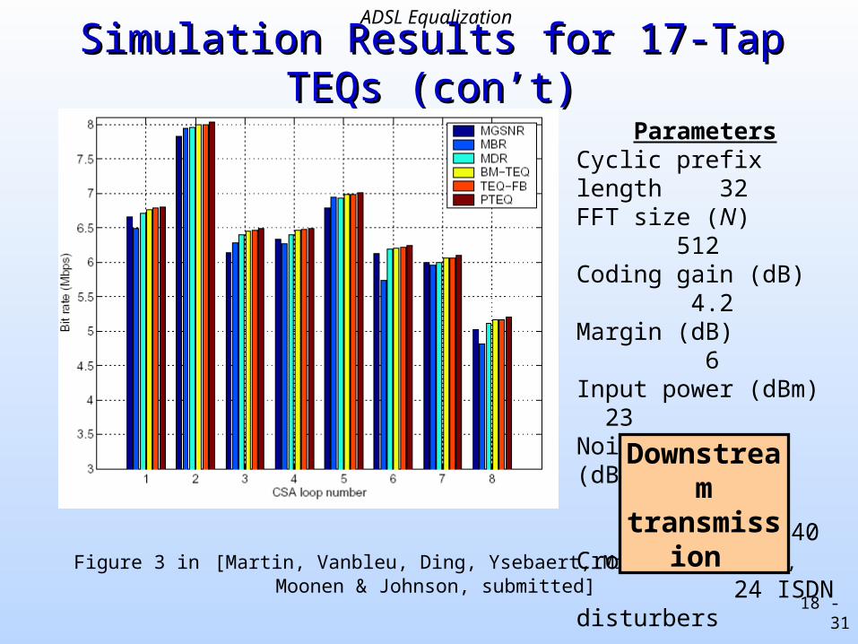
Simulation Results for 17-Tap TEQs (con’t)Simulation Results for 17-Tap TEQs (con’t)
ParametersCyclic prefix length 32FFT size (N) 512Coding gain (dB) 4.2Margin (dB) 6Input power (dBm) 23Noise power (dBm/Hz) -140Crosstalk noise 24 ISDN disturbers
Figure 3 in [Martin, Vanbleu, Ding, Ysebaert, Milosevic, Evans, Moonen & Johnson, submitted]
Downstream transmission
ADSL Equalization
18 - 32
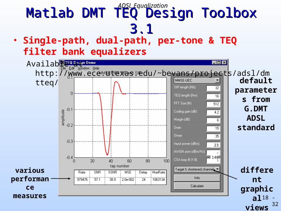
• Single-path, dual-path, per-tone & TEQ filter bank equalizersAvailable at http://www.ece.utexas.edu/~bevans/projects/adsl/dmtteq/
Matlab DMT TEQ Design Toolbox 3.1Matlab DMT TEQ Design Toolbox 3.1
variousperformance
measures
default parameters
from G.DMT ADSL
standard
different graphical
views
-140
23
ADSL Equalization

18 - 33
Multicarrier ModulationMulticarrier Modulation• Advantages
– Efficient use of bandwidth without full channel equalization
– Robust against impulsive noise and narrowband interference
– Dynamic rate adaptation
• Disadvantages– Transmitter: High signal peak-to-average power ratio
– Receiver: Sensitive to frequency and phase offset in carriers
• Open issues for point-to-point connections– Pulse shapes of subchannels (orthogonal, efficient realization)
– Channel equalizer design (increase bit rate, reduce complexity)
– Synchronization (timing recovery, symbol synchronization)
– Bit loading (allocation of bits in each subchannel)
• Open issues for coordinating multiple connections
18 - 34
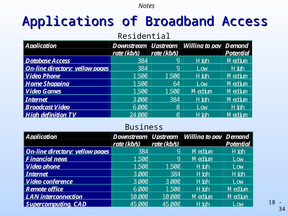
Application Downstream rate (kb/s)
Upstream rate (kb/s)
Willing to pay Demand Potential
Database Access 384 9 High Medium On-line directory; yellow pages 384 9 Low High Video Phone 1,500 1,500 High Medium Home Shopping 1,500 64 Low Medium Video Games 1,500 1,500 Medium Medium Internet 3,000 384 High Medium Broadcast Video 6,000 0 Low High High definition TV 24,000 0 High Medium
Application Downstream rate (kb/s)
Upstream rate (kb/s)
Willing to pay Demand Potential
On-line directory; yellow pages 384 9 Medium High Financial news 1,500 9 Medium Low Video phone 1,500 1,500 High Low Internet 3,000 384 High High Video conference 3,000 3,000 High Low Remote office 6,000 1,500 High Medium LAN interconnection 10,000 10,000 Medium Medium Supercomputing, CAD 45,000 45,000 High Low
Residential
Business
Applications of Broadband AccessApplications of Broadband AccessNotes
18 - 35
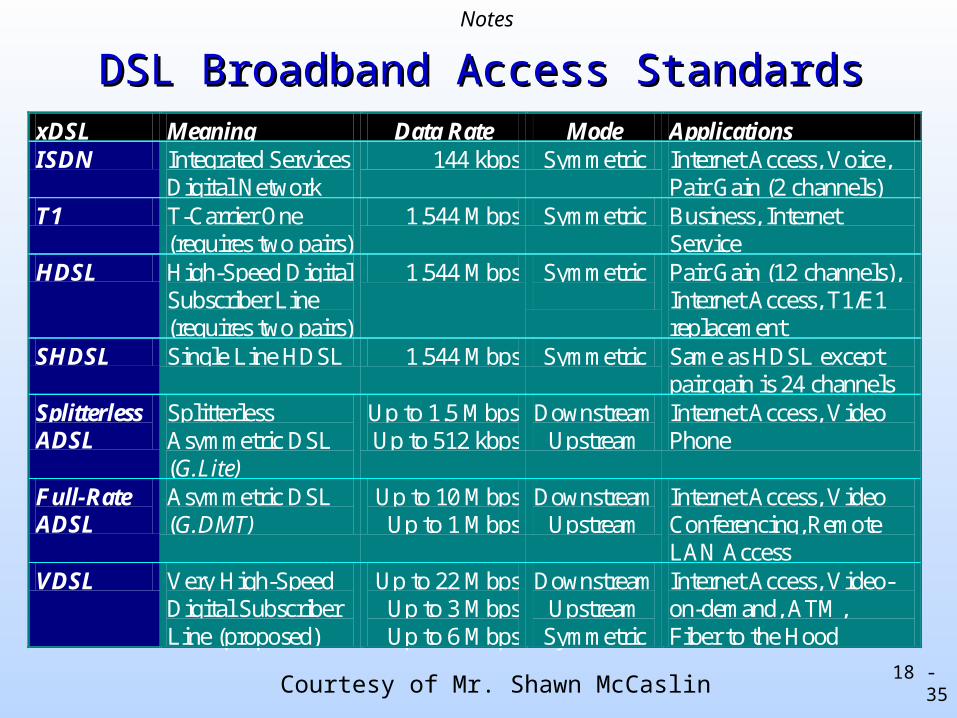
DSL Broadband Access StandardsDSL Broadband Access Standards
Courtesy of Mr. Shawn McCaslin
xDSL Meaning Data Rate Mode Applications ISDN Integrated Services
Digital Network 144 kbps Symmetric Internet Access, Voice,
Pair Gain (2 channels) T1 T-Carrier One
(requires two pairs) 1.544 Mbps Symmetric Business, Internet
Service HDSL High-Speed Digital
Subscriber Line (requires two pairs)
1.544 Mbps Symmetric
Pair Gain (12 channels), Internet Access, T1/E1 replacement
SHDSL Single Line HDSL 1.544 Mbps Symmetric Same as HDSL except pair gain is 24 channels
Splitterless ADSL
Splitterless Asymmetric DSL (G.Lite)
Up to 1.5 Mbps Up to 512 kbps
Downstream Upstream
Internet Access, Video Phone
Full-Rate ADSL
Asymmetric DSL (G.DMT)
Up to 10 Mbps Up to 1 Mbps
Downstream Upstream
Internet Access, Video Conferencing, Remote LAN Access
VDSL Very High-Speed Digital Subscriber Line (proposed)
Up to 22 Mbps Up to 3 Mbps Up to 6 Mbps
Downstream Upstream Symmetric
Internet Access, Video-on-demand, ATM, Fiber to the Hood
Notes
18 - 36
ADSL and Cable ModemsADSL and Cable Modems• Need for high-speed (broadband) data access
– Voiceband data modems can yield 53 kbps (kilobits per second) – Telephone voice channel capacity ois 64 kbps (the Central Office samples
voice signals at 8 kHz using 8 bits/sample)– Integrated Services Digital Network (ISDN) modems deliver 128 kbps– New modem standards are necessary to meet the demand for higher
bandwidth access for telecommuting, videoconferencing, video-on-demand, Internet service providers, Internet access, etc.
• Two standards tested in 1998 and now widely available– Cable modems– Asymmetric Digital Subscriber Line (ADSL) modems
• Cable Modems– Always connected to the Internet– Your neighbors on the same local area network share the bit rate– Local area network provides either 27 or 36 Mbps downstream, and
between 320 kbps and 10 Mbps upstream.
Notes
18 - 37
ADSL ModemsADSL Modems
• ADSL modems– Always connected to the Internet
– Call central office using a dedicated telephone line which also supports a conventional Plain Old Telephone Service (POTS) line for voice
– Connection time is 5-10 seconds
– ADSL modems are capable of delivering 1-10 Mbps from the central office to the customer (downstream) and 0.5-1 Mbps from the customer to the central office (upstream)
– Although ADSL lines have been available from Southwestern Bell since the Fall of 1997, ADSL modems were not commercially available until Fall of 1999.
Notes
18 - 38
Discrete Multitone (DMT) ModulationDiscrete Multitone (DMT) Modulation
• DMT uses multiple harmonically related carriers– Implemented as inverse Fast Fourier Transform (FFT) in transmitter
– Implemented using forward FFT in receiver
• Transmission bandwidth– 1.1 MHz downstream and 256 kHz upstream
– Limit of 1.1 MHz is due to power constraints imposed by the FCC
– For 18 kft telephone lines, the attenuation at 1.1 MHz is -120 dBm.
• Frequency domain is divided into 256 4.3-kHz bins– Channel 0 is dedicated to voice
– Channels 1-5 are not used due to compatibility with ISDN services.
Notes
18 - 39
Two Types of TransmissionTwo Types of Transmission
• Two versions of ADSL1. Frequency Division Multiplexing: the upstream and downstream
channels do not overlap: the upstream uses channels 6-31 and the downstream uses channels 32-255.
2. Echo Cancelled: the upstream and downstream channels overlap: the upstream uses channels 6-31 and the downstream uses channels 6-255.
• According to available SNR in each bin, bin carries– QAM signal whose constellation varies from 2-15 bits or
– no signal if SNR is less than 12 dB in that subchannel
• Constellations chosen so that overall bit error rate < 10-7
• Maximum transmission rate with symbol rate of 4 kHz– Downstream: 248 channels x 15 bits/channel x 4 kHz = 14.88 Mbps
– Upstream: 24 channels x 15 bits/channel x 4 kHz = 1.440 Mbps
Notes

18 - 40
Channel AttenuationChannel Attenuation• Reliable transmission of high-frequency information over a
telephone line is wrought with several challenges.– Telephone lines are unshielded and bundled 50 wires to a trunk. The
other lines in the bundle can cause severe crosstalk– Telephone lines attenuate signals. The attenuation increases with
increasing frequency. At 1.1 MHz, which is the highest transmitted frequency, the attenuation of a 24 gauge wire is
10 kft -70 dBm/Hz 16 kft -110 dBm/Hz 12 kft -90 dBm/Hz 18 kft -120 dBm/Hz 14 kft -100 dBm/Hz
• Because of severe effects in the channel, the ADSL standard defines channel coding using cyclic prefixes and employs error correcting codes
Notes
18 - 41
Bridge TapsBridge Taps
• Bridge Taps are unterminated lines– During modem initialization, effect of bridge taps is included in
channel estimate. Their effect would be to lower the possible channel capacity.
– During data transmission, bridge taps may saturate the front-end and at a least will be unpleasant for the echo canceller. The echo canceller should have an estimate of the echo channel including the bridge taps. Given that the reflected echo is almost instantaneous than the echo canceller channel estimate should capture them too.
• In G.lite, echo cancellation is optional– Modems who use it can still use it
– A bigger problem in G.lite is the phone due to the splitterless environment
– Transmitters that do not have an echo canceller system can rely on their receive filters to reduce the echo.
Notes
18 - 42
ADSL ModemsADSL Modems
• ADSL modem consists of a line driver plus 3 subsystems: 1. analog front end (15 V)
2. digital interface (3 V)
3. discrete multitone processor (3 V)
• Analog front end provides the analog-to-digital and digital-to-analog interfaces to the telephone line.
• Digital interace manages the input and output digital message streams.
• Discrete multitone processor implements the digital communications and signal processing to support the ADSL standard. An ADSL modem requires much greater than 200 Digital Signal Processor MIPS.
Notes
18 - 43
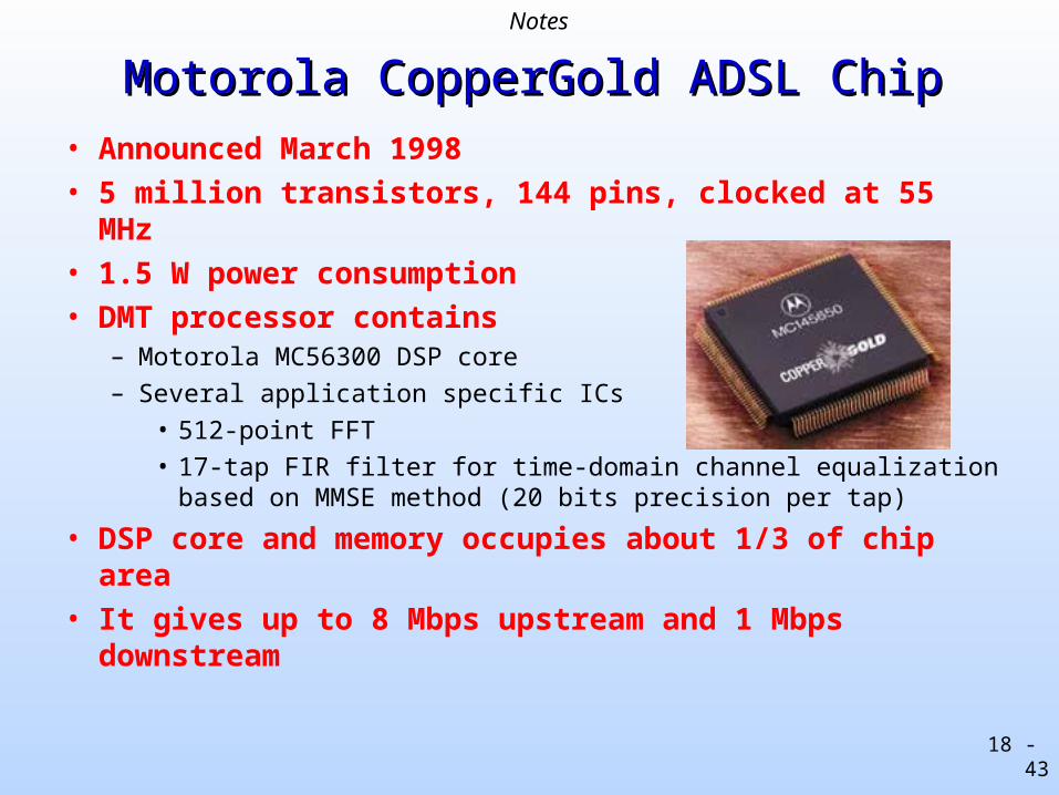
Motorola CopperGold ADSL ChipMotorola CopperGold ADSL Chip
• Announced March 1998
• 5 million transistors, 144 pins, clocked at 55 MHz
• 1.5 W power consumption
• DMT processor contains – Motorola MC56300 DSP core
– Several application specific ICs
• 512-point FFT
• 17-tap FIR filter for time-domain channel equalization based on MMSE method (20 bits precision per tap)
• DSP core and memory occupies about 1/3 of chip area
• It gives up to 8 Mbps upstream and 1 Mbps downstream
Notes
18 - 44
Motorola Copper Gold ADSL TransceiverMotorola Copper Gold ADSL Transceiver• Contains all 3 ADSL modem subsystems on a single chip.
– Has programmable bit to tell it whether it is at customer's or central office site
– Analog front end operates at a sampling rate of 2.208 MHz and gives 16 bits/sample of resolution. It uses sigma-delta modulation with an oversampling factor of 55 / 2.208 = 25.
• Discrete multitone processor consists of a Motorola MC56300 DSP Onyx core and several application-specific digital VLSI circuits to implement – 256-point FFT for downstream transmission or 512-point FFT for
downstream reception if it is at the central office or customer's site, respectively
– 17-tap adaptive FIR filter for channel equalization (20 bits of precision per tap) running at 2.208 MHz
– DSP core computes the 32-point FFT for the downstream transmission or the 64-point FFT for the downstream reception.
Notes
18 - 45
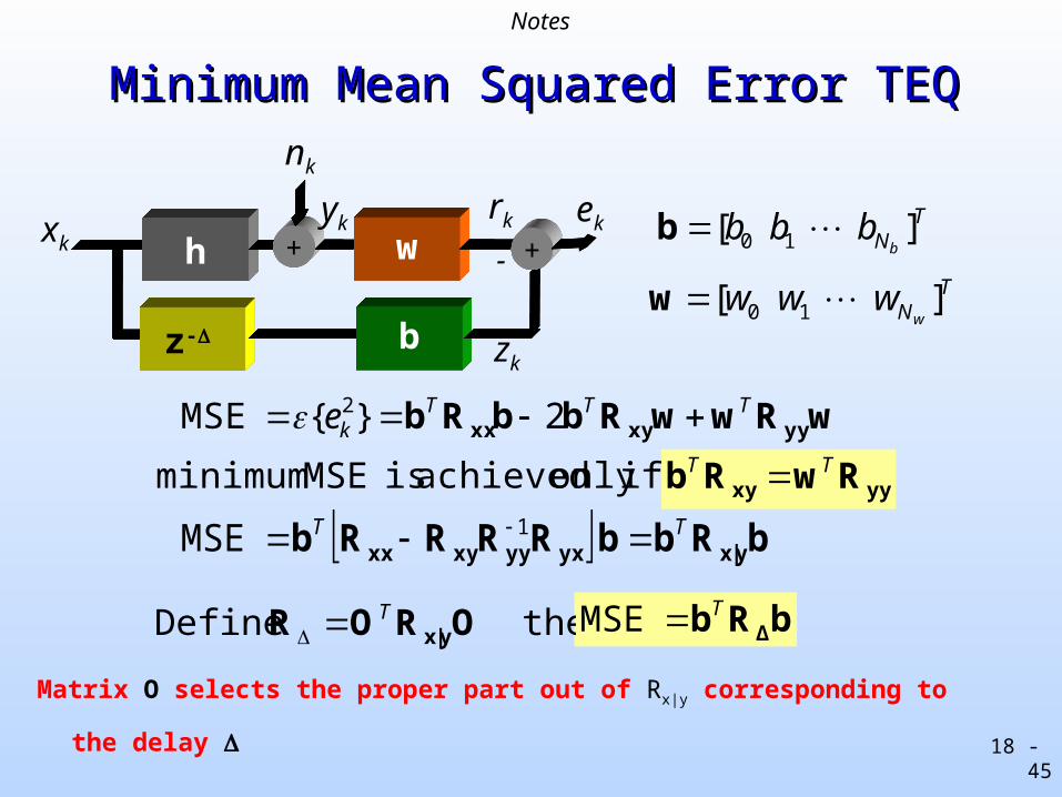
Minimum Mean Squared Error TEQMinimum Mean Squared Error TEQ
TNb
bbb ] [ 10 b
TNw
www ] [ 10 w
wRwwRbbRb yyxyxxTTT
ke 2}{MSE 2
ifonly achieved is MSE minimum
bRbbRRRRb y|xyxyyxyxxTT MSE 1
bRb ΔTMSE
Matrix O selects the proper part out of Rx|y corresponding to the delay
then Define OROR y|xT
yyxy RwRb TT
z-
h + w
b
-xk
yk ek
zk
rk
nk
+
Notes
18 - 46
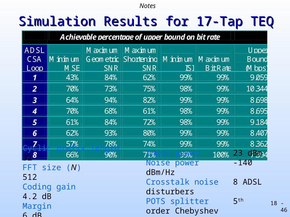
Simulation Results for 17-Tap TEQSimulation Results for 17-Tap TEQ Achievable percentage of upper bound on bit rate
ADSL CSA Loop
Minimum
MSE
Maximum Geometric
SNR
Maximum Shortening
SNR
Minimum
ISI
Maximum
Bit Rate
Upper Bound
(Mbps) 1 43% 84% 62% 99% 99% 9.059
2 70% 73% 75% 98% 99% 10.344
3 64% 94% 82% 99% 99% 8.698
4 70% 68% 61% 98% 99% 8.695
5 61% 84% 72% 98% 99% 9.184
6 62% 93% 80% 99% 99% 8.407
7 57% 78% 74% 99% 99% 8.362
8 66% 90% 71% 99% 100% 7.394
Cyclic prefix length 32FFT size (N) 512Coding gain 4.2 dBMargin 6 dB
Input power 23 dBmNoise power -140 dBm/HzCrosstalk noise 8 ADSL disturbersPOTS splitter 5th order Chebyshev
Notes
18 - 47
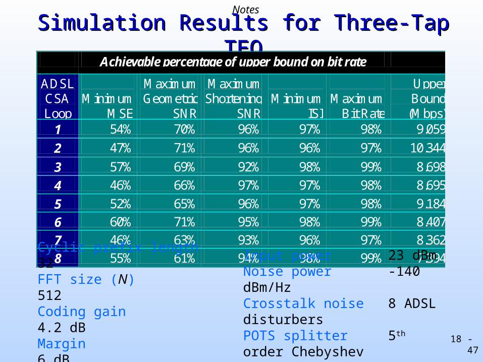
Simulation Results for Three-Tap TEQSimulation Results for Three-Tap TEQ Achievable percentage of upper bound on bit rate
ADSL CSA Loop
Minimum
MSE
Maximum Geometric
SNR
Maximum Shortening
SNR
Minimum
ISI
Maximum
Bit Rate
Upper Bound
(Mbps) 1 54% 70% 96% 97% 98% 9.059
2 47% 71% 96% 96% 97% 10.344
3 57% 69% 92% 98% 99% 8.698
4 46% 66% 97% 97% 98% 8.695
5 52% 65% 96% 97% 98% 9.184
6 60% 71% 95% 98% 99% 8.407
7 46% 63% 93% 96% 97% 8.362
8 55% 61% 94% 98% 99% 7.394
Cyclic prefix length 32FFT size (N) 512Coding gain 4.2 dBMargin 6 dB
Input power 23 dBmNoise power -140 dBm/HzCrosstalk noise 8 ADSL disturbersPOTS splitter 5th order Chebyshev
Notes