ads527xevm user's guide (rev. a) - ti.coms guide sbau093a– march ... p6 is used to connect...
TRANSCRIPT
1 Description
2 Power Supplies
User's GuideSBAU093A–March 2004–Revised October 2005
ADS527xEVM Evaluation Module
The ADS527xEVM is designed for ease of use in evaluating the performance of theADS527x of 10- and 12-bit analog-to-digital converters (ADCs) with low-voltagedifferential signal (LVDS) outputs.
Contents1 Description........................................................................................... 12 Power Supplies ..................................................................................... 13 Signals ............................................................................................... 24 Operation ............................................................................................ 25 Bill of Materials...................................................................................... 66 Schematic and PCB................................................................................ 8
List of Figures
1 Evaluation Board Overview ....................................................................... 32 Initial Startup Screen ............................................................................... 43 COM Port Selection Prompt....................................................................... 44 COM Port Drop-Down Selection List............................................................. 45 Register Access Program Screen ................................................................ 56 Register Access Program Screen – Custom Pattern Option ................................. 67 ADS527xEVM PCB – Top Layer ................................................................. 88 ADS527xEVM PCB – Ground Layer............................................................. 99 ADS527xEVM PCB – Power Layer............................................................. 1010 ADS527xEVM PCB – Bottom Layer............................................................ 11
List of Tables
1 Component List .................................................................................... 7
The ADS527xEVM is designed to provide ease of use in evaluating the performance of the ADS527xfamily of 10- and 12-bit ADCs with LVDS outputs. When combined with the ADSDeSer-50EVM, acomplete evaluation of the ADS527x family can be performed. The ADS527xEVM has the followingfeatures:
• Easy testing of the ADS527x family of 10 and 12-bit data converters• Single-ended, transformer-coupled inputs.• PC interface to control internal registers.
The ADS527x EVM requires four supplies:
• AVDD – 3.3V DUT analog supply• DVDD – 3.3V Digital supply for the microcontroller and RS232 level shifter• LVDD – 1.8V to 3.3V LVDS output driver supply
SBAU093A–March 2004–Revised October 2005 ADS527xEVM Evaluation Module 1

www.ti.com
3 Signals
3.1 External Reference
3.2 Inputs Signals
3.3 Output Signals
3.4 Clock Signal
4 Operation
4.1 Pushbuttons and Indicator LEDs
Signals
• AW – 3.3V Clock driver supply
All of the supplies can be connected to one 3.3V supply for ease of connectivity.
By default, the ADS527x EVM defaults to an internally generated referenc. However, by asserting SW3,the ADS527x will use the REFT and REFB supplied on P1 as its references.
The input signals are applied to SMA connectors J1, J3, J5, J7, J9, J11, J13 AND J15. The input signalsare transformer-coupled to the inputs of the ADC. There are no coupling capacitors, only resistors inseries with the converters inputs to the transformers.
The LVDS outputs from the ADC are sent to P6. P6 is used to connect the ADS527xEVM to theADSDeSer-50EVM to provide a means for deserializing the data for external processing.
Enter a clean, low jitter, 3Vpp clock on J17. The maximum clock frequency should be set with the aid ofthe device data sheet. Either a sinusoidal or square-wave clock input can be expected.
When power is applied to the board, the EVM performs an initialization sequence that sets the initialoperation of the ADS527x. The Ref LED lights up to signify that the Int/Ext reference is set to internal. TheRST LED is illuminated while a reset pulse is provided to the ADS527x to reset the device for properoperation. The EVM is now operational. If it is connected to the ADSDESer-50EVM and the resetpushbutton is pressed on the deserializer board, parallel data should be available on each channel output,and a clock should be present on the clock output.
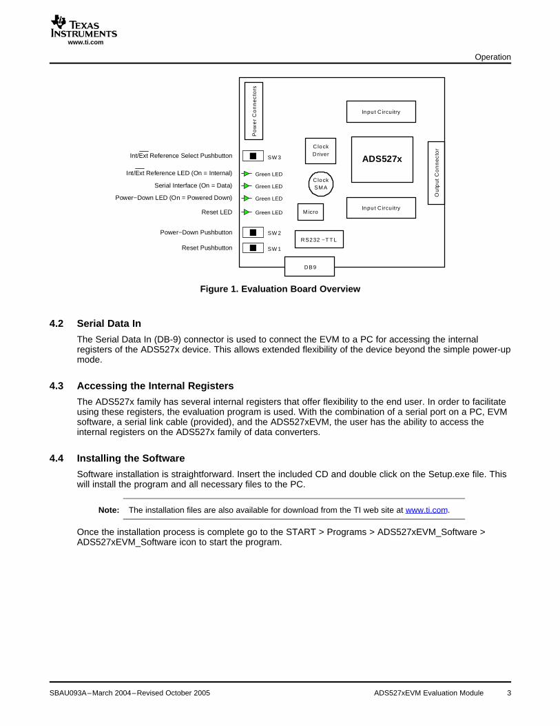
The ADS527xEVM has three pushbuttons and four indicator LEDs, as shown in Figure 1. Thepushbuttons and their corresponding LEDs are defined as follows:
• SW1 – RST – ADS527x device reset (resets only the ADS527x device).• SW2 – PD– ADS527x device power-down (LED on signifies that only the ADS527x device is in
complete power-down).• SW3 – Ref– Internal/External Reference Selection (LED on signifies Internal reference).
When illuminated, the fourth LED (SDI) signifies that data has been received from the PC through theserial link.
ADS527xEVM Evaluation Module2 SBAU093A–March 2004–Revised October 2005
www.ti.com
Int/Ext Reference Select Pushbutton
Int/Ext Reference LED (On = Internal)
Serial Interface (On = Data)
Power−Down LED (On = Powered Down)
Reset LED
Power−Down Pushbutton
Reset Pushbutton
ADS527x
Inpu t C ircuitry
Inpu t C ircuitry
Ou
tpu
tC
on
ne
cto
r
Micro
DB9
RS232 −T T L
SW 1
SW 2
SW 3
ClockDriver
ClockSMA
Po
we
rC
on
ne
cto
rs
Green LED
Green LED
Green LED
Green LED
4.2 Serial Data In
4.3 Accessing the Internal Registers
4.4 Installing the Software
Operation
Figure 1. Evaluation Board Overview
The Serial Data In (DB-9) connector is used to connect the EVM to a PC for accessing the internalregisters of the ADS527x device. This allows extended flexibility of the device beyond the simple power-upmode.
The ADS527x family has several internal registers that offer flexibility to the end user. In order to facilitateusing these registers, the evaluation program is used. With the combination of a serial port on a PC, EVMsoftware, a serial link cable (provided), and the ADS527xEVM, the user has the ability to access theinternal registers on the ADS527x family of data converters.
Software installation is straightforward. Insert the included CD and double click on the Setup.exe file. Thiswill install the program and all necessary files to the PC.
Note: The installation files are also available for download from the TI web site at www.ti.com.
Once the installation process is complete go to the START > Programs > ADS527xEVM_Software >ADS527xEVM_Software icon to start the program.
SBAU093A–March 2004–Revised October 2005 ADS527xEVM Evaluation Module 3

www.ti.com
4.5 Using the Software
Operation
After clicking on the ADS527xEVM_Software icon, an initial startup screen will be displayed, as shown inFigure 2. The COM Port Selection prompt, as shown in Figure 3, will appear in front of Figure 2.
Figure 2. Initial Startup Screen
Figure 3. COM Port Selection Prompt
Click OK and then select the proper COM port from the drop-down list, as shown in Figure 4. The programlists all available COM ports on your system to choose from. Once a COM port is selected, the mainprogram window will open. (This example only shows two COM ports listed. Results will vary based onyour actual system configuration.)
Figure 4. COM Port Drop-Down Selection List
ADS527xEVM Evaluation Module4 SBAU093A–March 2004–Revised October 2005
www.ti.com
4.6 Custom Pattern Generation
Operation
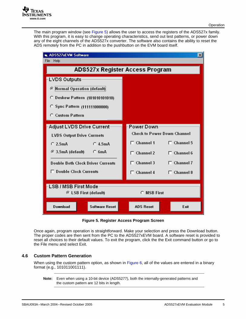
The main program window (see Figure 5) allows the user to access the registers of the ADS527x family.With this program, it is easy to change operating characteristics, send out test patterns, or power downany of the eight channels of the ADS527x converter. The software also contains the ability to reset theADS remotely from the PC in addition to the pushbutton on the EVM board itself.
Figure 5. Register Access Program Screen
Once again, program operation is straightforward. Make your selection and press the Download button.The proper codes are then sent from the PC to the ADS527xEVM board. A software reset is provided toreset all choices to their default values. To exit the program, click the the Exit command button or go tothe File menu and select Exit.
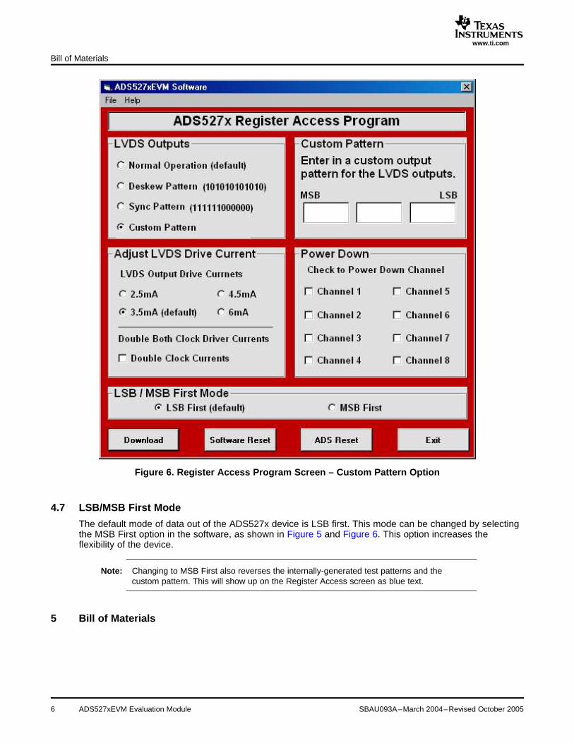
When using the custom pattern option, as shown in Figure 6, all of the values are entered in a binaryformat (e.g., 101011001111).
Note: Even when using a 10-bit device (ADS5277), both the internally-generated patterns andthe custom pattern are 12 bits in length.
SBAU093A–March 2004–Revised October 2005 ADS527xEVM Evaluation Module 5
www.ti.com
4.7 LSB/MSB First Mode
5 Bill of Materials
Bill of Materials
Figure 6. Register Access Program Screen – Custom Pattern Option
The default mode of data out of the ADS527x device is LSB first. This mode can be changed by selectingthe MSB First option in the software, as shown in Figure 5 and Figure 6. This option increases theflexibility of the device.
Note: Changing to MSB First also reverses the internally-generated test patterns and thecustom pattern. This will show up on the Register Access screen as blue text.
ADS527xEVM Evaluation Module6 SBAU093A–March 2004–Revised October 2005

www.ti.com
Bill of Materials
Table 1. Component ListMFG PART # INSTALLED DESCRIPTION MFG DO NOT COMMENTS
REF DES INSTALL
ADS527xPFC U1 IC, 10/12-BIT, 40-70MSPS, LVDS, See Note 18-CHANNEL A.D.C. (NOT IN
SOURCE)
CRCW040210R0F R1, R2 RES, 10 Ω, 0.1W, 1%, 0402 CHIP, VISHAY/DALETHICK FILM
CRCW040249R9F R6, R8, R9, R13, RES, 49.9 Ω, 0.1W, 1%, 0402 CHIP, VISHAY/DALER14, R18,R19, R23, THICK FILMR24,R28, R29,R33,R34, R38,R39,R43, R44,R54,R55, R56–R69,R83
CRCW0402000RF R4, R7, R10–R12, RES, 0.0 Ω, 0.1W, 1%, 0402 CHIP, VISHAY/DALE R5, R7, R11, R12,R15–R17, R20–R22M THICK FILM R16, R17, R21,R25–RR27, R22, R26, R27,R30–R32, R35–R37, R31, R32, R36,R40–R42, R45, R46 R37, R41, R42, R46
CRCW0402332RF R49–R52 RES, 332 Ω, 0.1W, 1%, 0402 CHIP, VISHAY/DALETHICK FILM
CRCW1206000 R70–R72 RES, 0.0 Ω, 0.125W, 0%, DALECHIP-JUMPER
CRCW04024751F R47, R48, R53 RES, 4.75 kΩ, 0.1W, 1%, 0402 CHIP, VISHAY/DALETHICK FILM
CRCW04025622F R3 RES, 56.2 kΩ, 0.1W, 1%, 0402 CHIP, VISHAY/DALETHICK FILM
ERJ-2RKF4990X R80–R82 RES, 499 Ω, 0.1W, 1%, 0402, CHIP Panasonic
CY8C27243-24PVXI U4 IC, MICROCONTROLLER, 8-bit PSoC See Note 2(NOT INSOURCE)
DEKL-9SAT-F P5 CONN, DB9, RTANG RECPT 0.318 W/ CINCHSCRW. LCKS.
ECJ0EB1A104K C2, C3, C5, C14, CAP, 0.1 µF, 10VDC, 10%, CERAMIC PanasonicC18, C21, C23, MULTILAYER CHIPC24–C26, C30, C31,C33, C35, C37, C39,C41, C43–C45,C47–C49, C51–C53,C55–C57, C59–C61,C63–C65, C67–C69,C71–C78
ECJ0EB1C103K C16, C17, C80 CAP, 0.01 µF, 16VDC, 10%, CERAMIC PanasonicMULTILAYER CHIP
ECJ0EB1H102K C19, C20, C22, CAP, 0.001 µF, 50V DC, 10% PanasonicC27–C29, C32, C34, CERAMIC MULTILAYER 0402C36, C38, C40
ECJ0EC1H100K C42, C46, C50, C54, CAP, 10 pF, 50V DC, 10% CERAMIC PanasonicC58, C62, C66, C70 MULTILAYER 0402
ECJ1VB1C104K C6, C9, C10, C12 CAP, 0.1 µF, 16VDC, 10%, CERAMIC PanasonicMULTILAYER CHIP
EVQPJB04K SW1–SW3 SWITCH, SPST, PCB MOUNT
MAX3221CDB U3 No PDB description available
MC100EPT21DT U2 IC, 3.3V TRANSLATOR, On SemiconductorDIFFERENTIAL LVPECL to LVTTL
PTR AK550 3 P1–P3 TERM. BLK, 3 POS POWERCONNECTOR
QTH-040-01-F-D-DP-A P6 CONN, 80 PIN SMT, HI SPEED SAMTECTERMINAL STRIP
SML-LX1206-GC-TR CR1–CR4 LED, SMT 1206, GREEN
TTWB-4-B T1–T8 XFMR, RF, 0.1–1500 MHz COILCRAFT
T491B225K016AS C1, C4 CAP, 2.2 µF, 16V, 10%, TANTALUM KEMETCHIP-MOLDED
T491B475K016AS C7, C8, C11, C13 CAP, 4.7 µF, 16V, 10%, TANTALUM KEMETCHIP-MOLDED
SBAU093A–March 2004–Revised October 2005 ADS527xEVM Evaluation Module 7
www.ti.com
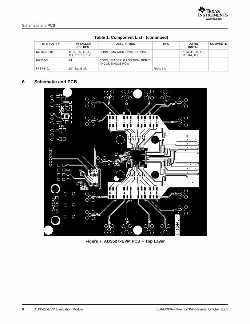
6 Schematic and PCB
Schematic and PCB
Table 1. Component List (continued)MFG PART # INSTALLED DESCRIPTION MFG DO NOT COMMENTS
REF DES INSTALL
142-0701-201 J1, J3, J5, J7, J9, CONN, SMA JACK 0.2CC LO-COST J2, J4, J6, J8, J10,J11, J13, 15, J17 J12, J14, J16
102203-3 P4 CONN, HEADER, 6 POSITION, RIGHTANGLE, SINGLE ROW
SRS4-8-01 1/2" Stand offs Richo Inc.
Figure 7. ADS527xEVM PCB – Top Layer
ADS527xEVM Evaluation Module8 SBAU093A–March 2004–Revised October 2005

www.ti.com
Schematic and PCB
Figure 8. ADS527xEVM PCB – Ground Layer
SBAU093A–March 2004–Revised October 2005 ADS527xEVM Evaluation Module 9
www.ti.com
Schematic and PCB
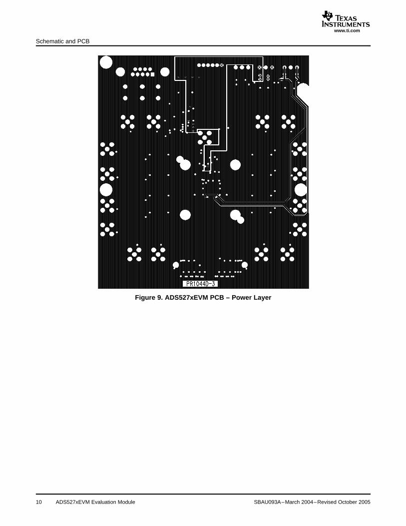
Figure 9. ADS527xEVM PCB – Power Layer
ADS527xEVM Evaluation Module10 SBAU093A–March 2004–Revised October 2005
www.ti.com
Schematic and PCB
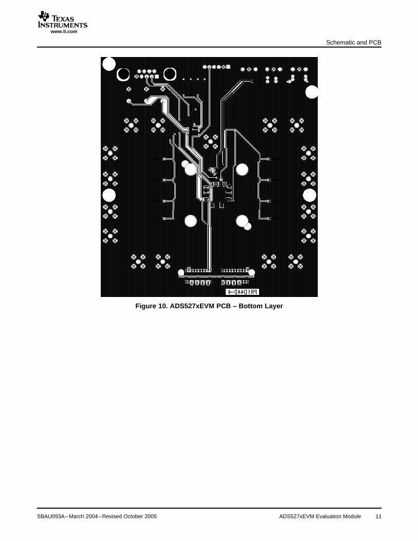
Figure 10. ADS527xEVM PCB – Bottom Layer
SBAU093A–March 2004–Revised October 2005 ADS527xEVM Evaluation Module 11


IMPORTANT NOTICE
Texas Instruments Incorporated and its subsidiaries (TI) reserve the right to make corrections, modifications,enhancements, improvements, and other changes to its products and services at any time and to discontinueany product or service without notice. Customers should obtain the latest relevant information before placingorders and should verify that such information is current and complete. All products are sold subject to TI’s termsand conditions of sale supplied at the time of order acknowledgment.
TI warrants performance of its hardware products to the specifications applicable at the time of sale inaccordance with TI’s standard warranty. Testing and other quality control techniques are used to the extent TIdeems necessary to support this warranty. Except where mandated by government requirements, testing of allparameters of each product is not necessarily performed.
TI assumes no liability for applications assistance or customer product design. Customers are responsible fortheir products and applications using TI components. To minimize the risks associated with customer productsand applications, customers should provide adequate design and operating safeguards.
TI does not warrant or represent that any license, either express or implied, is granted under any TI patent right,copyright, mask work right, or other TI intellectual property right relating to any combination, machine, or processin which TI products or services are used. Information published by TI regarding third-party products or servicesdoes not constitute a license from TI to use such products or services or a warranty or endorsement thereof.Use of such information may require a license from a third party under the patents or other intellectual propertyof the third party, or a license from TI under the patents or other intellectual property of TI.
Reproduction of information in TI data books or data sheets is permissible only if reproduction is withoutalteration and is accompanied by all associated warranties, conditions, limitations, and notices. Reproductionof this information with alteration is an unfair and deceptive business practice. TI is not responsible or liable forsuch altered documentation.
Resale of TI products or services with statements different from or beyond the parameters stated by TI for thatproduct or service voids all express and any implied warranties for the associated TI product or service andis an unfair and deceptive business practice. TI is not responsible or liable for any such statements.
Following are URLs where you can obtain information on other Texas Instruments products and applicationsolutions:
Products Applications
Amplifiers amplifier.ti.com Audio www.ti.com/audio
Data Converters dataconverter.ti.com Automotive www.ti.com/automotive
DSP dsp.ti.com Broadband www.ti.com/broadband
Interface interface.ti.com Digital Control www.ti.com/digitalcontrol
Logic logic.ti.com Military www.ti.com/military
Power Mgmt power.ti.com Optical Networking www.ti.com/opticalnetwork
Microcontrollers microcontroller.ti.com Security www.ti.com/security
Telephony www.ti.com/telephony
Video & Imaging www.ti.com/video
Wireless www.ti.com/wireless
Mailing Address: Texas Instruments
Post Office Box 655303 Dallas, Texas 75265
Copyright 2005, Texas Instruments Incorporated