administration manual for cisco unified contact center ... · administration guide for cisco...
TRANSCRIPT

Administration Manual for Cisco Unified Contact Center Management Portal
Release 7.5(1) April 2009
Corpora te HeadquartersCisco System s, Inc.170 West Tasman DriveSan Jo se, CA 95134-1706 USAhttp://ww w.cisco .comTel: 408 526-4000
800 553-NETS (6387)Fax: 408 526-4100

ii Administration Guide for Cisco Unified Contact Center Management Portal Release 7.5(1)
THE SPECIFICATIONS AND INFORMATION REGARDING THE PRODUCTS IN THIS MANUAL ARE
SUBJECT TO CHANGE WITHOUT NOTICE. ALL STATEMENTS, INFORMATION, AND
RECOMMENDATIONS IN THIS MANUAL ARE BELIEVED TO BE ACCURATE BUT ARE PRESENTED
WITHOUT WARRANTY OF ANY KIND, EXPRESS OR IMPLIED. USERS MUST TAKE FULL
RESPONSIBILITY FOR THEIR APPLICATION OF ANY PRODUCTS.
THE SOFTWARE LICENSE AND LIMITED WARRANTY FOR THE ACCOMPANYING PRODUCT ARE SET
FORTH IN THE INFORMATION PACKET THAT SHIPPED WITH THE PRODUCT AND ARE
INCORPORATED HEREIN BY THIS REFERENCE. IF YOU ARE UNABLE TO LOCATE THE SOFTWARE
LICENSE OR LIMITED WARRANTY, CONTACT YOUR CISCO REPRESENTATIVE FOR A COPY.
The Cisco implementation of TCP header compression is an adaptation of a program developed by the University of
California, Berkeley (UCB) as part of UCB’s public domain version of the UNIX operating system. All rights
reserved. Copyright © 1981, Regents of the University of California.
NOTWITHSTANDING ANY OTHER WARRANTY HEREIN, ALL DOCUMENT FILES AND SOFTWARE OF
THESE SUPPLIERS ARE PROVIDED “AS IS” WITH ALL FAULTS. CISCO AND THE ABOVE-NAMED
SUPPLIERS DISCLAIM ALL WARRANTIES, EXPRESSED OR IMPLIED, INCLUDING, WITHOUT
LIMITATION, THOSE OF MERCHANTABILITY, FITNESS FOR A PARTICULAR PURPOSE AND
NONINFRINGEMENT OR ARISING FROM A COURSE OF DEALING, USAGE, OR TRADE PRACTICE.
IN NO EVENT SHALL CISCO OR ITS SUPPLIERS BE LIABLE FOR ANY INDIRECT, SPECIAL,
CONSEQUENTIAL, OR INCIDENTAL DAMAGES, INCLUDING, WITHOUT LIMITATION, LOST PROFITS
OR LOSS OR DAMAGE TO DATA ARISING OUT OF THE USE OR INABILITY TO USE THIS MANUAL,
EVEN IF CISCO OR ITS SUPPLIERS HAVE BEEN ADVISED OF THE POSSIBILITY OF SUCH DAMAGES.
CCVP, the Cisco logo, and the Cisco Square Bridge logo are trademarks of Cisco Systems, Inc.; Changing the Way
We Work, Live, Play, and Learn is a service mark of Cisco Systems, Inc.; and Access Registrar, Aironet, BPX,
Catalyst, CCDA, CCDP, CCIE, CCIP, CCNA, CCNP, CCSP, Cisco, the Cisco Certified Internetwork Expert logo,
Cisco IOS, Cisco Press, Cisco Systems, Cisco Systems Capital, the Cisco Systems logo, Cisco Unity,
Enterprise/Solver, EtherChannel, EtherFast, EtherSwitch, Fast Step, Follow Me Browsing, FormShare, GigaDrive,
HomeLink, Internet Quotient, IOS, iPhone, IP/TV, iQ Expertise, the iQ logo, iQ Net Readiness Scorecard, iQuick
Study, LightStream, Linksys, MeetingPlace, MGX, Networking Academy, Network Registrar, PIX, ProConnect,
ScriptShare, SMARTnet, StackWise, The Fastest Way to Increase Your Internet Quotient, and TransPath are
registered trademarks of Cisco Systems, Inc. and/or its affiliates in the United States and certain other countries.
All other trademarks mentioned in this document or Website are the property of their respective owners. The use of
the word partner does not imply a partnership relationship between Cisco and any other company. (0708R)
Administration Guide for Cisco Unified Contact Center Management Portal
Copyright © 2008, Cisco Systems, Inc.
All rights reserved.

Administration Guide for Cisco Unified Contact Center Management Portal Release 7.5(1) iii iii
CONTENTS
1 UNIFIED CONTACT CENTER MANAGEMENT PORTAL OVERVIEW ..................................................................................... 8
Operational Overview .................................................................................... 8
2 WEB SERVER ........................................................................... 9
Import a Tenant from the ICM ....................................................................... 9
How does it work? ......................................................................................... 9
Portal Users .................................................................................................... 9
Host Administrator First Steps .................................................................. 10
Configuring Imported Resource Data........................................................ 10
Single Sign-On ............................................................................................. 11 Administrator Account Setup .................................................................. 11 Configuring Management Portal Authentication ..................................... 12 Managing Users with Single Sign-On ..................................................... 13
Creating a Tenant Administrator ................................................................ 13 Assigning Administrator Privileges .......................................................... 14 Using the Agent Password Reset Utility ................................................. 14
3 SYSTEM PROVISIONING ....................................................... 16
Security Management ................................................................................. 16
System Management ................................................................................... 16
4 BULK UPLOAD ....................................................................... 17
Member Attributes ....................................................................................... 17
Editing CSV files .......................................................................................... 17
Template Guide ............................................................................................ 17 Global Template Columns....................................................................... 17 Agent Template ....................................................................................... 19 Folders Template .................................................................................... 20 Agent Desktop Template......................................................................... 20 Agent Team Template............................................................................. 21 Enterprise Skill Group Template ............................................................. 21 Skill Group Template ............................................................................... 21 User Variable Template .......................................................................... 22
iv Administration Guide for Cisco Unified Contact Center Management Portal Release 7.5(1)
Using the Bulk Upload Tool ........................................................................ 22 Data Types .............................................................................................. 23 Agent Security Field Example ................................................................. 23 Reasons for Upload Failure .................................................................... 24
5 AUDIT TRAILS ........................................................................ 25
Audit Histories ............................................................................................. 25
Audit Reports ............................................................................................... 25
6 SYSTEM ARCHITECTURE ..................................................... 27
Web Application........................................................................................... 27
Application Server ....................................................................................... 28
Reporting Services ...................................................................................... 28
Data Import Server ...................................................................................... 28
Resource States........................................................................................... 28
State Descriptions ....................................................................................... 29 Synchronize ............................................................................................ 29 Ready ......................................................................................................29 Error .........................................................................................................30 Delete Pending ........................................................................................ 30 Delete Confirmed .................................................................................... 30
User Interface ............................................................................................... 31
Database Codes ........................................................................................... 31
Memberships ................................................................................................ 32
Example Synchronize Microflow ................................................................ 32
State Machine Scenarios ............................................................................ 33
7 SYSTEM OPERATIONS .......................................................... 36
Service Restart Configuration .................................................................... 36
Database Backup and Recovery ................................................................ 36
Changing the Active Importer Server ........................................................ 37
8 CONNECTION MONITORING ................................................. 41

Administration Guide for Cisco Unified Contact Center Management Portal Release 7.5(1) v v
Performance Counters ................................................................................ 41 CCMP Data Pipeline object .................................................................... 41 CCMP Application Datasources object ................................................... 42 CCMP Application Monitoring object ...................................................... 42 CCMP Application Server object ............................................................. 42
Event Log Alarms ........................................................................................ 43
9 SNMP CONFIGURATION ........................................................ 44 Stage 1 - Configure the alarm generator ................................................ 44 Stage 2 - Add alarms to the Windows event log ..................................... 44 Stage 3 - Setup the Windows SNMP service ......................................... 44
Alarms Reference ........................................................................................ 45 Alarm Service has Started ...................................................................... 45 Alarm Service has Stopped .................................................................... 45 Customer Script is Online ....................................................................... 45 Customer Script is Offline ....................................................................... 46 Failed Transactions ................................................................................. 46 Timed Out Transactions .......................................................................... 47 Rejected Transactions ............................................................................ 47
Trap Guidelines............................................................................................ 48
10 SysMon ................................................................................... 49
Installing SysMon ........................................................................................ 49
The Configuration File ................................................................................ 49 Configuration ........................................................................................... 49 Alerts .......................................................................................................49 Monitors .................................................................................................. 51
11 INDEX ...................................................................................... 55

vi Administration Guide for Cisco Unified Contact Center Management Portal Release 7.5(1)
Preface
Purpose
This document explains how to adminstrate and provision the Unified
Contact Center Management Portal platform.
Audience
This document is intended for all users of the Unified Contact Center
Management Portal, from high-level administrators to team supervisors.
The reader needs no technical understanding beyond a basic knowledge of
how to use computers.
Organization
Chapter 1, “Unified Contact Center Management Portal Overview”
Provides information on the components that make up the Unified
Contact Center Management Portal and the configuration that needs to
be done for each.
Chapter 2, “Web Server”
Explains how to set up the essential users and equipment within the
Web Server so that tenant users can use it to view reports and perform
administrative tasks upon their own resources, such as importing data
from an ICM into a tenant folder.
Chapter 3, “System Provisioning”
Introduces system security and system management and explains
where to find further information.
Chapter 4, “Bulk Upload”
This chapter details the process required to bulk upload dimension
data into the Unified Contact Center Management Portal, the templates
used to do so and details on how to understand any upload failure.
Chapter 5, “Audit Trails”
Describes the audit histories of individual items and the audit report
used to measure actions taken upon entities in the Unified Contact
Center Management Portal.
Chapter 6, "System Architecture"
Describes how the system operates, including system architecture,
possible resource states and the effects events have on these states.
Chapter 7, "System Operations"
Describes best practices within the Unified Contact Center
Management Portal system, and the management of the Database
Servers.
Chapter 8, “Provisioning Component Monitoring”

Administration Guide for Cisco Unified Contact Center Management Portal Release 7.5(1) vii vii
Explains how to use the Provisioning component monitoring web site
for the Unified Contact Center Management Portal Provisioning
component. This allows support agents to monitor busy times,
capacity statistics, event logs and so on, and provides access to audit
reporting for the Unified Contact Center Management Portal.
Chapter 9, “SNMP Configuration”
Explains how to set up SNMP traps for the Unified Contact Center
Management Portal Provisioning component, and describes the traps
that it raises.
Obtaining Documentation, Obtaining Support, and Security Guidelines
For information on obtaining documentation, obtaining support, providing
documentation feedback, security guidelines, and also recommended
aliases and general Cisco documents, see the monthly What‟s New in
Cisco Product Documentation, which also lists all new and revised Cisco
technical documentation, at:
http://www.cisco.com/en/US/docs/general/whatsnew/whatsnew.html
8 Administration Guide for Contact Center Management Portal Release 7.5(1) 8
1 UNIFIED CONTACT CENTER MANAGEMENT PORTAL OVERVIEW
Operational Overview
The Unified Contact Center Management Portal is a suite of server
components that simplify the operations and procedures for performing
basic administrative functions such as managing agents and equipment,
and provide a common, web-based user interface within the entire Cisco
IPCC Hosted and Enterprise Editions product set.
The Unified Contact Center Management Portal consists of four
components:
The Database server component, which utilizes an application called
the Importer to import enterprise data from different data sources into
a Microsoft SQL Server 2005 management information database. The
database consists of separate database elements that sit on top of SQL
Server and which provide data to different reporting elements:
o The RDBMS Database (known as the Datamart) holds the
imported enterprise data
o The Reporting Services Database imports and processes data
from the datamart so that SQL Server Reporting Services can
use it to populate reports
The Application server component manages security and failover. It
manages security by ensuring that users can only view specific folders
and folder content as defined by their security login credentials. It
verifies that a user is valid and then loads the system configuration that
applies to that user. It also manages failover, so if one database server
fails, the application can automatically retrieve the required data via an
alternative database server
The Web server component provides a user interface to the platform
that allows users to interact with report data, as well as performing
administrative functions
The Data Import server component is an Extract, Transform and
Load (ETL) server for data warehouses. The Data Import component
imports the data used to build reports. It is designed to handle high
volume data (facts) such as call detail records as well as data that is
rarely changed (dimensions) such as agents, peripherals and skill
groups
If these components are installed on more than one machine, the Data
Import and Database components are normally installed on the Database
Server. The Application and Web components are usually installed on the
Web Application Server.
Administration Guide for Contact Center Management Portal Release 7.5(1) 9
9
2 WEB SERVER The Unified Contact Center Management Portal web component is a
browser-based management application designed for use by contact
center/system administrators, business users and supervisors. The host
administrator does not administrate the web component server on a day-to-
day basis, but must set up a tenant administrator user to do so, and a tenant
folder in which to put all the tenant‟s resources.
Further information on the web server is available from the User Manaul
for Unified Contact Center Management Portal Release 7.5(1).
Import a Tenant from the ICM
All tenant data in the Unified Contact Center Management Portal platform
is derived from imported customer definition data on the ICM. All changes
to the customer (tenant) data are performed using Cisco‟s Configuration
Manager.
How does it work?
The Unified Contact Center Management Portal maintains a complete data
model of the contact center equipment to which it is connected and
periodically synchronized. In addition to configuration information, for
example agents or skill-groups, the Unified Contact Center Management
Portal can optionally record the events logged by the equipment, such as
call records for management information and reporting purposes. The
Unified Contact Center Management Portal data model and
synchronization activity allows for items to be provisioned either through
the Unified Contact Center Management Portal's Web interface or from
the standard equipment specific user interfaces.
Portal Users
In regards to the Web component server there are typically a small number
of different user types:
The host administrator is responsible for the whole platform and
therefore has a view across all the equipment and resources
The tenant administrator is responsible for the slice of the system
assigned to the tenant by the host administrator
The tenant user has access only to the resources and tools assigned by
the tenant administrator. Several sub-classes of tenant user may be
created by the tenant administrator using user groups and roles to
achieve their business requirements, for example one type of user may
be able to add information notices
On a new system the host and tenant administrators perform their
respective tasks before the tenant user is given access to the system. These
tasks are detailed below.

10 Administration Guide for Contact Center Management Portal Release 7.5(1) 10
Host Administrator First Steps
The Host administrator is responsible for:
Creating a tenant
Ensuring that the tenant equipment (peripherals) are correctly located
in the tenant folder
Creating an administrator user for each tenant
Adding them to the administrators group for the tenant and assigning
any specific roles
Note To map a prefix to a tenant for the importing of ICM data, the user must
have host administrator privileges.
Configuring Imported Resource Data
After the initial data import, resources imported from CallManagers
associated with specific tenants will be stored in those tenant folders.
Where multiple tenants share a CallManager, resources will be put in the
Unallocated folder and the administrator must place these in the
appropriate folder. Resources associated with more than one tenant, such
as phone types and button templates, should be placed in a subfolder of the
Shared folder that should be set to be readable only by users from those
tenants. More information on how to manage security in the Management
Portal can be found in the User Manual for Cisco Unified Contact Center
Management Portal Release 7.5(1).
Caution: Resources may not be moved out of tenant folders
Prefixes can be used to search through items in the Unallocated folder and
identify the specific items to be moved into a selected tenant folder.
Note
You can only map a prefix to a tenant folder
Any single item moved to a folder is excluded from the prefix
management import job to prevent it from being automatically moved
by the system
To view the prefixes in the system that apply to tenant folder data:
1. Click Tools. The Tools page is displayed
2. Click System Manager. The System Manager page is displayed
3. From the Filter drop down list select Tenant. The page refreshes
and the tenant folders in the system are displayed as a list
4. Click the properties icon displayed next to the prefix name. To the
right of the screen the Update the details for the selected tenant
folder section is displayed
5. Click the View Prefixes... link. The prefixes associated with the
selected tenant are displayed as a list
To create a prefix (add a prefix to a system folder), click the Create
Prefix button. The Create a Prefix page is displayed. Perform the
following:

Administration Guide for Contact Center Management Portal Release 7.5(1) 11
11
1. In the Prefix field enter the prefix
2. From the Type drop down list, select the system resource type to
which the prefix is to be applied
3. In the Priority field enter a unique numerical value (0 - 9999)
4. Click OK
To edit a prefix, click the properties icon displayed next to the prefix
name. To the right of the screen the Update the details for the selected
tenant section is displayed.
1. You may only modify the name entered in the Prefix field
2. Click OK
Note Once a prefix has been created, its type cannot be changed.
To assign a priority to a prefix, use the up or down buttons displayed next
to the prefix name. The higher the prefix is in the list, the more relevant
and useful it is to your data.
To delete a prefix, select the tenant folder in the tree whose associated
prefixes you wish to view. The prefixes associated with the selected folder
are listed.
Click the red cross displayed next to the prefix you want to delete.
Single Sign-On
By default, it is necessary for users to login to the Portal every time they
connect. The Portal can, however, be configured to use Single Sign-On
(SSO), which allows users to connect without logging in by linking their
Portal user accounts with their Windows user accounts.
Note Users cannot login via SSO over a proxy connection.
Caution Setting up SSO will delete any existing Portal user accounts which are
not in domain login format. You will need to set up new Portal user
accounts for all existing users.
Administrator Account Setup
Warning It is vital that a new administrator account be set up correctly as the
existing administrator account will be deleted when SSO is configured.
1. Login to the Portal as „administrator‟
2. In the User Manager, create a user account to be the new
administrator account. The login name should be of the form
<DOMAIN>\<your domain login>, for example
CCMPDOM\jsmith. The password should conform to the
password security specified in System Settings, but will never be
used
3. Click on the new user and open the Groups tab
4. Click Add to Group
5. Check the checkbox of the Administrators group
6. Close and save

12 Administration Guide for Contact Center Management Portal Release 7.5(1) 12
You may now proceed to configure SSO for the Management Portal.
Configuring Management Portal Authentication
1. From the location where you installed the Management Portal (this
will normally be C:\Program Files \Management Portal), navigate
to the Application Server folder
2. Open the XML file
Exony.Reporting.Application.Server.exe.config
Note Some text editors, such as Wordpad, will not save an XML file correctly,
which will cause problems with the Management Portal. Always back up
the config file before making changes.
3. Locate the section:
<Exony.Reporting.Application.Security.Security>
<setting name="Authentication" serializeAs="String">
<value>Portal</value><!--SSO|Portal-->
</setting>
</Exony.Reporting.Application.Security.Security>
and change Portal to SSO
<Exony.Reporting.Application.Security.Security>
<setting name="Authentication" serializeAs="String">
<value>SSO</value><!--SSO|Portal-->
</setting>
</Exony.Reporting.Application.Security.Security>
4. Save and close
5. Run services.msc and restart the Management Portal
Application Server service
6. Open Internet Information Services (IIS) Manager and select
Web Sites > Default Web Site
7. Right-click on Portal and select Properties
8. On the Directory Security tab:
Edit… Authentication and access control
Ensure that only Integrated Windows authentication is
checked. Uncheck any other options, particularly Enable
anonymous access (normally found at the top of the
window), and click OK
9. On the Custom Errors tab:
Select each 401 error in turn and click Edit…
Ensure the Message type: is File
Ensure the File: is set to the Portal redirect401.htm file
which is by default found at C:\Program Files
\Management Portal\Web\redirect401.htm
10. Click OK to close the Edit Custom Error Properties window.
Leave IIS open, as you will need to restart it when you have
finished configuring SSO

Administration Guide for Contact Center Management Portal Release 7.5(1) 13
13
11. From the location where you installed the Management Portal (this
will normally be C:\Program Files\Management Portal), right-
click on the Web folder and click Properties
12. On the Security tab, click Advanced and ensure that the Allow
inheritable permissions from the parent to propogate to this
object and all child objects option is checked
13. Give Read and Read & Execute properties on the Web directory
to all domain users who should have access to the Management
Portal
Note It may be advisable to create a Portal Users group that future Portal users
can be added to to avoid the necessity of performing this step repeatedly
14. Click OK to close the Advanced Security Settings and Web
Properties windows
15. Double click on the Web folder and open the web.config file
16. Locate the section:
<setting name="AuthenticationProvider" serializeAs="String">
<value>Portal</value><!--SingleSignOn|Portal-->
and change Portal to SingleSignOn:
<setting name="AuthenticationProvider" serializeAs="String">
<value>SingleSignOn</value><!--SingleSignOn|Portal-->
17. In IIS, right-click on the current machine and select All Tasks >
Restart IIS…
You will now be able to access the Management Portal from your domain
account without logging in.
Managing Users with Single Sign-On
Once SSO has been set up, all Portal users must be given a Portal login in
the form <DOMAIN>\<Windows domain login>. This means that
previously-existing Portal user accounts must be recreated in the new
format before any users can login.
Each time a new user is given a Portal account, that user must either be
given Read and Read & Execute properties on the Web directory as
described above, or added to a user group that has those permissions.
Each new user will also need to add the Portal to their list of trusted sites
in Internet Explorer.
Creating a Tenant Administrator
1. Click on the Tools link at the top right of the web page to display the
Tools page
2. Click on Security Manager, and the Security Manager page is
displayed
3. Click on the Users tab to the top left to access the User Browser page.
4. Select the tenant folder and click New
14 Administration Guide for Contact Center Management Portal Release 7.5(1) 14
5. Fill in the following fields:
In the User Name field enter the name as it will appear in the
system for the new user
In the Password field enter the password for the new user
In the Confirm Password field re-enter the selected password
In the First Name and Last Name fields enter the user's details
In the Email field enter the email address of the new user
In the Description field enter any explanatory text, if required
6. Select the Advanced Mode checkbox and any of the following
checkboxes if applicable:
The Enabled checkbox to ensure that the user is live in the
system. If unchecked the new user is saved in the system but
cannot access it
The User must change password at next Logon checkbox to
prompt the new user to change their password after their first
login
The Password Never Expires checkbox to assign the password
to the new user indefinitely
The User cannot change password checkbox to prevent the
new user from being able to change their password
Note Only the User Name, Password and Confirm Password fields are required.
7. Click OK. You are returned to the User Browser page
Assigning Administrator Privileges
Now you must give the tenant administrator the permissions necessary to
manage the system. This is done by assigning the new user to the
administration group that was automatically created when you created the
tenant.
1. Click on the properties icon for the administrator user to display the
Edit User page
2. Click on the Groups tab to show the available groups
Note All users created are automatically assigned to the group <tenant> Users.
3. Select the group <tenant> Administrators. The user‟s permissions are
automatically updated so that they can manage users, folders,
information notices and folder security within the tenant folder
Using the Agent Password Reset Utility
Cisco Unified Communications Management Portal 7.5(1) provides a
Change Your Agent Password utility from which agents can change their
own passwords.
This page is reached by navigating to the URL: http://<Portal Web
Server>/Portal/agent_manage_password.aspx. You do not need to have a
Portal user account to use the Change Your Agent Password page.

Administration Guide for Contact Center Management Portal Release 7.5(1) 15
15
To change a password:
1. Enter the Agent Username. (This is the login name that you use to
log into the peripheral).
2. Enter the agents current password.
3. Enter your new password for the agent, and confirm.
Note Password changes are subject to a small time delay whilst the
they are committed to the Cisco Intelligent Communications
Manager.
Password Complexity Rules
Passwords for agents must conform to the password complexity rules
defined in the Cisco Unified Communications Management Portal.
The following settings may be configured:
Password Format
Minimum Password Length
Maximum Password Length
For more information about changing the password complexity rules in
Cisco Unified Communications Management Portal, please refer to the
section on Security Settings located in the User Manual.

16 Administration Guide for Contact Center Management Portal Release 7.5(1) 16
3 SYSTEM PROVISIONING All system and security management for the Management Portal is
performed through the web interface. For further information on how to
use the web interface, please see the accompanying User Manual. Most
system and security management after the initial setup is performed by
individual tenant administrators.
Security Management
Security Management can be thought of as the process of determining
which users can perform which actions in which folders. This involves
creating and managing the following entities:
Folders The security system used by the Management Portal is based
on a hierarchical folder structure where child folders may inherit
permissions from their parent. This means that the folder hierarchy
should ideally be designed with security requirements in mind
Users and Groups Users can be assigned to groups of users with the
same security permissions. A number of predefined groups with
commonly required permissions are provided
Roles and Tasks The actions that can be performed within a folder.
Each task is an individual kind of action, such as browsing resources
or managing information notices. These tasks are collected together
into roles. For example, you could create an Auditor role that included
the ability to manage audit reports, browse audit reports, and browse
resources, and then assign individual users the ability to perform that
role within certain folders
Note For each role a user or group is assigned, they must also be assigned an
equivalent global role. Removing a global role removes that user‟s ability
to perform the corresponding non-global roles anywhere within the
system, meaning it is possible to remove permissions in a single click
where necessary. The default groups have the correct global permissions
preassigned.
Security is explained in more detail in the Security Management chapter of
the User Manual.
System Management
The System Manager tool allows the user to create and manage resources
and resource folders within a hierarchical folder structure. Users with
sufficient security privileges can access and manage the entire contents of
the system via the System Manager interface. This lets you remotely
configure and administer key aspects of your IPCC system.
Administration Guide for Contact Center Management Portal Release 7.5(1) 17
17
4 BULK UPLOAD The bulk upload tool is used to import hundreds of resource items into the
Unifed Contact Center Management Portal Platform. It is used to generate
dimensions such as an Agent or a Skill-Group by filling in dimension
attributes using the standard CSV format.
All CSV files require headers which dictate where each value goes. To
facilitate this the Unifed Contact Center Managemret Portal uses
templates. Templates are a CSV file with all the headers set up. There is a
Template for every dimension type; for example, one for Agents, one for
Skill-Groups, and so forth.
Note Templates do not inform you the value type allowed in the field, for
example, numeric values.
Member Attributes
Member attributes such as Peripheral Member or Desk Setting Member
can always be removed from the CSV file completely, this means the
relationship will never be set in any row in the CSV file. Alternatively you
can leave this field blank, so there will be no relationship for that particular
row.
Editing CSV files
You can use Notepad, or any other text-based editor to edit CSV files.
Excel also offers support for CSV files so you can edit these in a familiar
environment whilst maintaining the integrity of the CSV format.
NoteThere are a few known issues with Excel and the CSV format. If you find
the CSV is corrupt after editing it in Excel, edit the file in a standard text
editor such as Notepad and check the file for missing commas.
Template Guide
This section runs through every Template and describes the columns
included in the Template.
For further information about the Data Type column in the tables below
see the Data Types on page 23.
Global Template Columns
These columns are common to every template file.
The Required? column in the tables below tells you if you can remove the
column should you not wish to set a value. An asterisk indicates that this
column cannot support a field that is empty.
The Description column tells you if you may leave the field blank.
Anything with No in this column must appear in every CSV file otherwise
the upload will fail.

18 Administration Guide for Contact Center Management Portal Release 7.5(1) 18
COLUMN
NAME
DATA-
TYPE
REQUIRED? DESCRIPTION
Path Path No Describes where in the Tree
the dimension will be created.
If you wish to supply the path
in the bulk upload screen, you
must remove this column.
Note If you leave the column
present and do not set a
value, it will attempt to
upload into the Root
directory, which is valid
for items such as
folders, but not for
resources such as Agent
or Skill Group.
Removing the column
completely allows you
to control the path via
the bulk upload control
screen.
Name SNC Yes* The name of the dimension in
the Portal. This must be
unique and won‟t ever be
provisioned.
Description - Yes Describes the dimension
being created. This never gets
provisioned.
Enterprise
Name
SNC Yes* The name for the dimension
being created. This does get
provisioned and cannot be
omitted. If you leave it blank
an Enterprise name is
generated for you.
Effective
From
Date No* The date from which the
dimension is active from,
default is today.
Effective To Date No* The date from which the
dimension is inactive default
is today.
Administration Guide for Contact Center Management Portal Release 7.5(1) 19
19
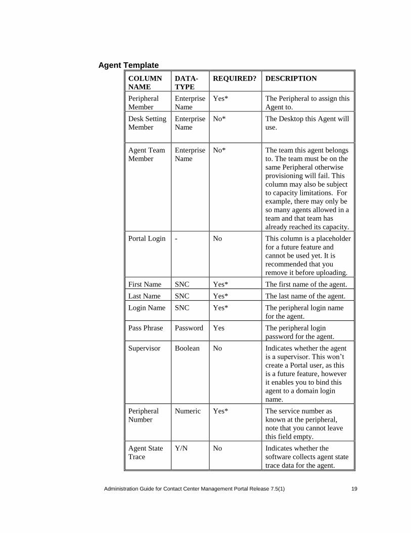
Agent Template
COLUMN
NAME
DATA-
TYPE
REQUIRED? DESCRIPTION
Peripheral
Member
Enterprise
Name
Yes* The Peripheral to assign this
Agent to.
Desk Setting
Member
Enterprise
Name
No* The Desktop this Agent will
use.
Agent Team
Member
Enterprise
Name
No* The team this agent belongs
to. The team must be on the
same Peripheral otherwise
provisioning will fail. This
column may also be subject
to capacity limitations. For
example, there may only be
so many agents allowed in a
team and that team has
already reached its capacity.
Portal Login - No This column is a placeholder
for a future feature and
cannot be used yet. It is
recommended that you
remove it before uploading.
First Name SNC Yes* The first name of the agent.
Last Name SNC Yes* The last name of the agent.
Login Name SNC Yes* The peripheral login name
for the agent.
Pass Phrase Password Yes The peripheral login
password for the agent.
Supervisor Boolean No Indicates whether the agent
is a supervisor. This won‟t
create a Portal user, as this
is a future feature, however
it enables you to bind this
agent to a domain login
name.
Peripheral
Number
Numeric Yes* The service number as
known at the peripheral,
note that you cannot leave
this field empty.
Agent State
Trace
Y/N No Indicates whether the
software collects agent state
trace data for the agent.
20 Administration Guide for Contact Center Management Portal Release 7.5(1) 20
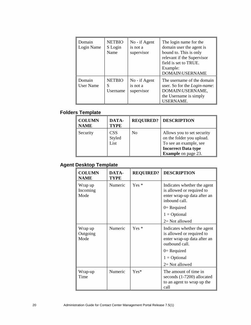
Domain
Login Name
NETBIO
S Login
Name
No - if Agent
is not a
supervisor
The login name for the
domain user the agent is
bound to. This is only
relevant if the Supervisor
field is set to TRUE.
Example:
DOMAIN\USERNAME
Domain
User Name
NETBIO
S
Username
No - if Agent
is not a
supervisor
The username of the domain
user. So for the Login-name:
DOMAIN\USERNAME,
the Username is simply
USERNAME.
Folders Template
COLUMN
NAME
DATA-
TYPE
REQUIRED? DESCRIPTION
Security CSS
Styled
List
No Allows you to set security
on the folder you upload.
To see an example, see
Incorrect Data type
Example on page 23.
Agent Desktop Template
COLUMN
NAME
DATA-
TYPE
REQUIRED? DESCRIPTION
Wrap up
Incoming
Mode
Numeric Yes * Indicates whether the agent
is allowed or required to
enter wrap-up data after an
inbound call.
0= Required
1 = Optional
2= Not allowed
Wrap up
Outgoing
Mode
Numeric Yes * Indicates whether the agent
is allowed or required to
enter wrap-up data after an
outbound call.
0= Required
1 = Optional
2= Not allowed
Wrap-up
Time
Numeric Yes* The amount of time in
seconds (1-7200) allocated
to an agent to wrap up the
call
Administration Guide for Contact Center Management Portal Release 7.5(1) 21
21
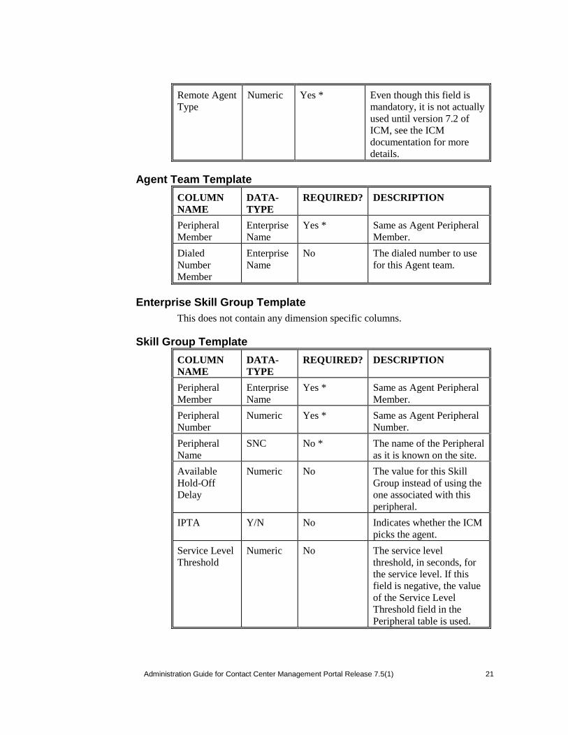
Remote Agent
Type
Numeric Yes * Even though this field is
mandatory, it is not actually
used until version 7.2 of
ICM, see the ICM
documentation for more
details.
Agent Team Template
COLUMN
NAME
DATA-
TYPE
REQUIRED? DESCRIPTION
Peripheral
Member
Enterprise
Name
Yes * Same as Agent Peripheral
Member.
Dialed
Number
Member
Enterprise
Name
No The dialed number to use
for this Agent team.
Enterprise Skill Group Template
This does not contain any dimension specific columns.
Skill Group Template
COLUMN
NAME
DATA-
TYPE
REQUIRED? DESCRIPTION
Peripheral
Member
Enterprise
Name
Yes * Same as Agent Peripheral
Member.
Peripheral
Number
Numeric Yes * Same as Agent Peripheral
Number.
Peripheral
Name
SNC No * The name of the Peripheral
as it is known on the site.
Available
Hold-Off
Delay
Numeric No The value for this Skill
Group instead of using the
one associated with this
peripheral.
IPTA Y/N No Indicates whether the ICM
picks the agent.
Service Level
Threshold
Numeric No The service level
threshold, in seconds, for
the service level. If this
field is negative, the value
of the Service Level
Threshold field in the
Peripheral table is used.
22 Administration Guide for Contact Center Management Portal Release 7.5(1) 22
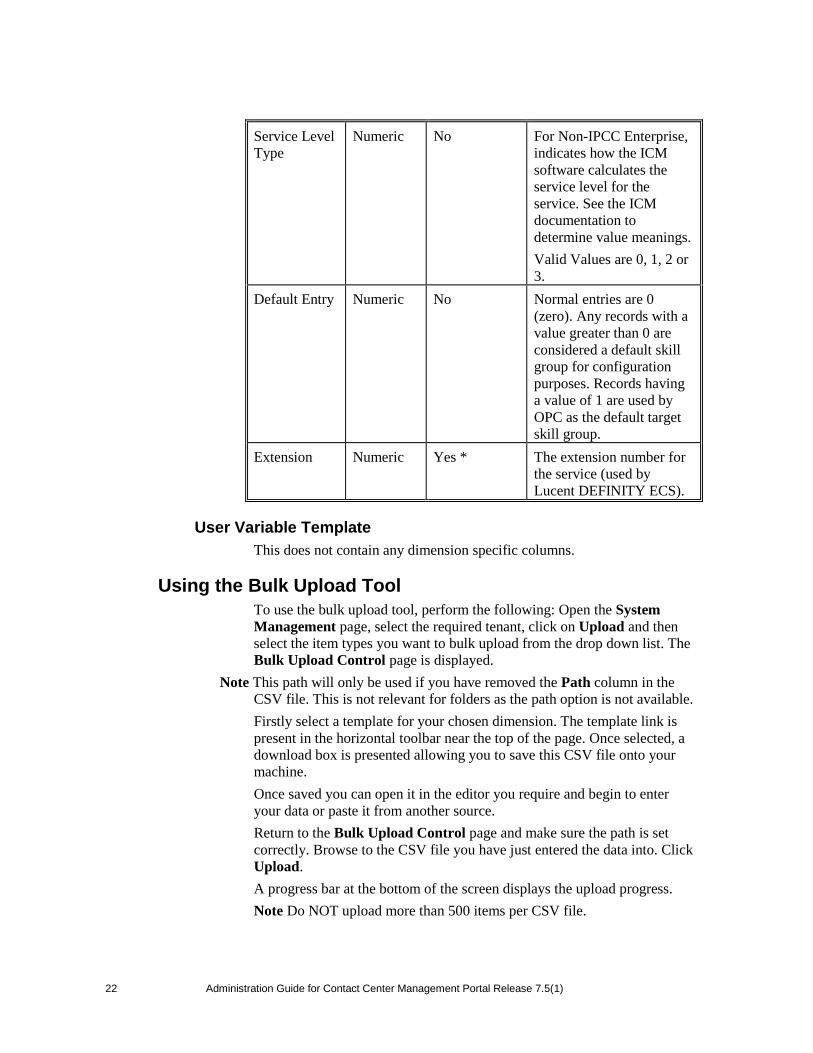
Service Level
Type
Numeric No For Non-IPCC Enterprise,
indicates how the ICM
software calculates the
service level for the
service. See the ICM
documentation to
determine value meanings.
Valid Values are 0, 1, 2 or
3.
Default Entry Numeric No Normal entries are 0
(zero). Any records with a
value greater than 0 are
considered a default skill
group for configuration
purposes. Records having
a value of 1 are used by
OPC as the default target
skill group.
Extension Numeric Yes * The extension number for
the service (used by
Lucent DEFINITY ECS).
User Variable Template
This does not contain any dimension specific columns.
Using the Bulk Upload Tool
To use the bulk upload tool, perform the following: Open the System
Management page, select the required tenant, click on Upload and then
select the item types you want to bulk upload from the drop down list. The
Bulk Upload Control page is displayed.
Note This path will only be used if you have removed the Path column in the
CSV file. This is not relevant for folders as the path option is not available.
Firstly select a template for your chosen dimension. The template link is
present in the horizontal toolbar near the top of the page. Once selected, a
download box is presented allowing you to save this CSV file onto your
machine.
Once saved you can open it in the editor you require and begin to enter
your data or paste it from another source.
Return to the Bulk Upload Control page and make sure the path is set
correctly. Browse to the CSV file you have just entered the data into. Click
Upload.
A progress bar at the bottom of the screen displays the upload progress.
Note Do NOT upload more than 500 items per CSV file.
Administration Guide for Contact Center Management Portal Release 7.5(1) 23
23
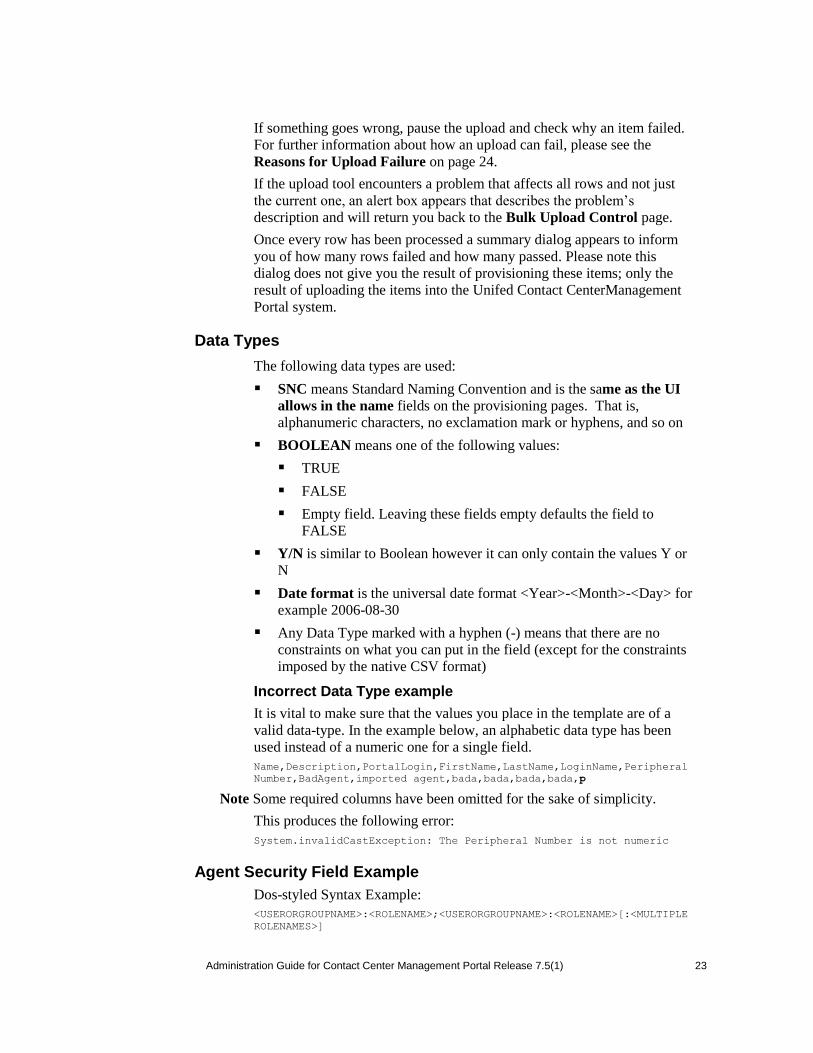
If something goes wrong, pause the upload and check why an item failed.
For further information about how an upload can fail, please see the
Reasons for Upload Failure on page 24.
If the upload tool encounters a problem that affects all rows and not just
the current one, an alert box appears that describes the problem‟s
description and will return you back to the Bulk Upload Control page.
Once every row has been processed a summary dialog appears to inform
you of how many rows failed and how many passed. Please note this
dialog does not give you the result of provisioning these items; only the
result of uploading the items into the Unifed Contact CenterManagement
Portal system.
Data Types
The following data types are used:
SNC means Standard Naming Convention and is the same as the UI
allows in the name fields on the provisioning pages. That is,
alphanumeric characters, no exclamation mark or hyphens, and so on
BOOLEAN means one of the following values:
TRUE
FALSE
Empty field. Leaving these fields empty defaults the field to
FALSE
Y/N is similar to Boolean however it can only contain the values Y or
N
Date format is the universal date format <Year>-<Month>-<Day> for
example 2006-08-30
Any Data Type marked with a hyphen (-) means that there are no
constraints on what you can put in the field (except for the constraints
imposed by the native CSV format)
Incorrect Data Type example
It is vital to make sure that the values you place in the template are of a
valid data-type. In the example below, an alphabetic data type has been
used instead of a numeric one for a single field.
Name,Description,PortalLogin,FirstName,LastName,LoginName,Peripheral
Number,BadAgent,imported agent,bada,bada,bada,bada,p
Note Some required columns have been omitted for the sake of simplicity.
This produces the following error:
System.invalidCastException: The Peripheral Number is not numeric
Agent Security Field Example
Dos-styled Syntax Example:
<USERORGROUPNAME>:<ROLENAME>;<USERORGROUPNAME>:<ROLENAME>[:<MULTIPLE
ROLENAMES>]

24 Administration Guide for Contact Center Management Portal Release 7.5(1) 24
This is an example of what can be put into the Security field in the agent
CSV file.
// #1 a single user with a single role
Administrator:Tenant User
// #2 a single user with more than one role
Administrator:Tenant User:Tenant Supervisor
// #3 multiple users
Administrator:Tenant User:Tenant Supervisor;User1:Tenant User
Users are separated by semicolons, and the user and roles are separated by
colons. This is very similar to the CSS syntax with the exception that a
user or group can have multiple roles rather than one value.
Reasons for Upload Failure
The table below details the causes as to why an upload can fail.
EXCEPTION TYPE REASON
No Capacity Left The capacity limit has been reached.
Enterprise Name Already Exists The enterprise name already exists.
Login Name Already Exists The peripheral login name already
exists.
SQL Exception The SQL error during upload, usually
due to bad data.
Argument Exception An attribute contains a bad value. It is
usually an exception because you
have an empty string in the Path
column when attempting to upload
items which cannot live in the Root
folder.
Security Exception You do not have security permissions
to upload to here.
Format Exception Invalid data in a column.
No Identity Available Identity not available.
Administration Guide for Contact Center Management Portal Release 7.5(1) 25
25
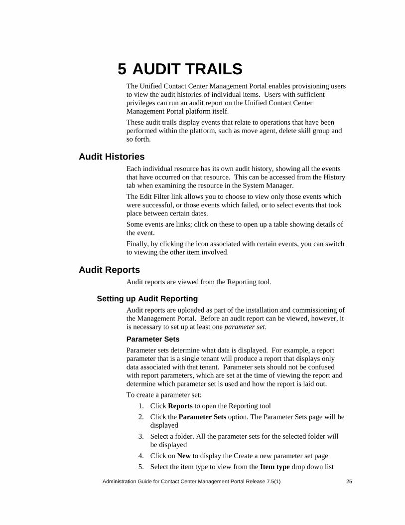
5 AUDIT TRAILS The Unified Contact Center Management Portal enables provisioning users
to view the audit histories of individual items. Users with sufficient
privileges can run an audit report on the Unified Contact Center
Management Portal platform itself.
These audit trails display events that relate to operations that have been
performed within the platform, such as move agent, delete skill group and
so forth.
Audit Histories
Each individual resource has its own audit history, showing all the events
that have occurred on that resource. This can be accessed from the History
tab when examining the resource in the System Manager.
The Edit Filter link allows you to choose to view only those events which
were successful, or those events which failed, or to select events that took
place between certain dates.
Some events are links; click on these to open up a table showing details of
the event.
Finally, by clicking the icon associated with certain events, you can switch
to viewing the other item involved.
Audit Reports
Audit reports are viewed from the Reporting tool.
Setting up Audit Reporting
Audit reports are uploaded as part of the installation and commissioning of
the Management Portal. Before an audit report can be viewed, however, it
is necessary to set up at least one parameter set.
Parameter Sets
Parameter sets determine what data is displayed. For example, a report
parameter that is a single tenant will produce a report that displays only
data associated with that tenant. Parameter sets should not be confused
with report parameters, which are set at the time of viewing the report and
determine which parameter set is used and how the report is laid out.
To create a parameter set:
1. Click Reports to open the Reporting tool
2. Click the Parameter Sets option. The Parameter Sets page will be
displayed
3. Select a folder. All the parameter sets for the selected folder will
be displayed
4. Click on New to display the Create a new parameter set page
5. Select the item type to view from the Item type drop down list

26 Administration Guide for Contact Center Management Portal Release 7.5(1) 26
6. Click Create Parameter Set
7. From the Folders tab, select the folder containing the resources,
and choose whether you will be adding items in subfolders as well
8. From the Resources tab, select the resources. You may choose to
see resources only from the folder you have selected, or from its
sub folders also
9. Click Add to add the specified resources to the parameter set
10. You may also remove resources from the parameter set by
checking them and clicking Remove
11. Select the Save As option
12. In the Name field enter a name for the new report (parameter set)
13. Click OK
Vewing an Audit Report
More information on viewing reports is available in the User Manual.
There are a number of audit reports available for use within the
Management Portal. These are:
Audit Data Report This report shows every provisioning change that
has occurred within the system during the specified time period. This
includes the name of the resource, the name of the user who made the
edit, and whether the change was successful
Daily Audit Summary This summarizes the changes made to
resources during the day, showing the percentage and total of
successful and failed changes at different times for individual items
Weekly Audit Summary This summarizes the changes made to
resources during the last week, showing the percentage and total of
successful and failed changes on different days for individual items
Monthly Audit Summary This summarizes the changes made to
resources during the last month, showing the percentage and total of
successful and failed changes on different days for individual items
Monitor Report This shows the current state of the Portal‟s
connections, essentially providing system monitoring (see Chapter 8
on page 41) through the web interface

Administration Guide for Contact Center Management Portal Release 7.5(1) 27
27
6 SYSTEM ARCHITECTURE The Unified Contact Center Management Portal system architecture is
shown below. The top half of the diagram is a traditional three tier
application. This includes a presentation layer (an ASP.NET web
application), a business logic application server and a SQL Server 2000
database. The lower half of the system architecture is a process
orchestration and systems integration layer called the Data Import Server.
Web Application
The user interface to the Unified Contact Center Management Portal is via
a web application that is accessed by a web browser (Microsoft Internet
Explorer). Access to the Unified Contact Center Management Portal
application is gained through a secure login screen. Every user has a
unique user name. This user name is assigned privileges by the system
administrator, which define the system functions the user can access and
perform.

28 Administration Guide for Contact Center Management Portal Release 7.5(1) 28
The user interface is time-zone aware and connections to it are secured
through HTTPS. The web application is hosted on the server by Microsoft
Internet Information Services (IIS) and so is suitable for lockdown in
secure environments.
Application Server
The Unified Contact Center Management Portal Application Server
component provides a secure layer in which all business logic is
implemented. The application server component runs in a separate service
and is always hosted with the web server component. The application
server component also includes caching to improve performance and
audits all actions taken by logged in users.
Reporting Services
The Unified Contact Center Management Portal utilizes Microsoft
Reporting Services technology for generating reports. Microsoft
Reporting Services is an integral part of SQL Server Enterprise Edition.
The Unified Contact Center Management Portal provides a flexible
reporting system in which reports are authored in the industry standard
Report Definition Language (RDL).
Data Import Server
The Data Import Server component is an Extract, Transform and Load
application for the Unified Contact Center Management Portal. The Data
Import Server component imports the data used in the Unified Contact
Center Management Portal. It is designed to handle high volume data
(facts), such as call detail records as well as data which is changed
irregularly (resources), such as agents, peripherals and skill groups.
The Data Import Server component is also responsible for monitoring
changes in the Unified Contact Center Management Portal system and
ensuring that those changes are updated onto the Cisco ICM and
CallManager. The Data Import Server component orchestrates the
creation, deletion and update of resources to the Cisco ICM and
CallManager.
The Microflow Runtime is the heart of the Data Import Server
component. It orchestrates systems without resorting to low level
programming languages. The Microflow Runtime is a general purpose
scripting environment and can be applied to a wide range of problems. The
term microflow describes any modular, reusable and independent unit of
business logic. An example microflow might update an agent on the Cisco
ICM when changes are made in the Unified Contact Center Management
Portal web server component.
Resource States
A resource is any kind of entity on the Cisco ICM or CICM and
CallManager, for example agents, teams, skill groups and phones. All the
resources in the Unified Contact Center Management Portal participate in

Administration Guide for Contact Center Management Portal Release 7.5(1) 29
29
a state machine. A state machine is a collection of states which a resource
will progress through during its lifetime. It is important to understand the
state machine when trouble shooting problems in the Unified Contact
Center Management Portal. The states are shown below:
State Descriptions
Synchronize
Synchronize is the initial state for all dimension items created through the
Unified Contact Center Management Portal.
It is also the initial state for any dimension item that is created by the
importer. This ensures that dimension items created on an external system,
such as a CICM, are provisioned on all other systems controlled by the
Unified Contact Center Management Portal, such as the CallManager.
Each dimension type (agent, tenant, skill group and so forth) has a separate
idempotent Synchronize microflow. (By idempotent it is meant that no
matter how many times the microflow is launched, conflicts or errors will
not be generated as a result). The role of the Synchronize microflow is to
bring all externally controlled systems in line with the Unified Contact
Center Management Portal database.
When a dimension item is in the Synchronize state, no updates are
accepted from importer microflows, with the exception that the item may
be changed to the Delete Pending state. This business logic ensures that
the Unified Contact Center Management Portal database acts as conflict
master.
Ready
Ready is the normal state of a dimension item in the Unified Contact
Center Management Portal database. It indicates that the dimension item
has been fully provisioned on all the external systems controlled by the
Unified Contact Center Management Portal.
If the user interface edits a dimension item then it is changed to the
Synchronize state. If an importer microflow updates a dimension item
30 Administration Guide for Contact Center Management Portal Release 7.5(1) 30
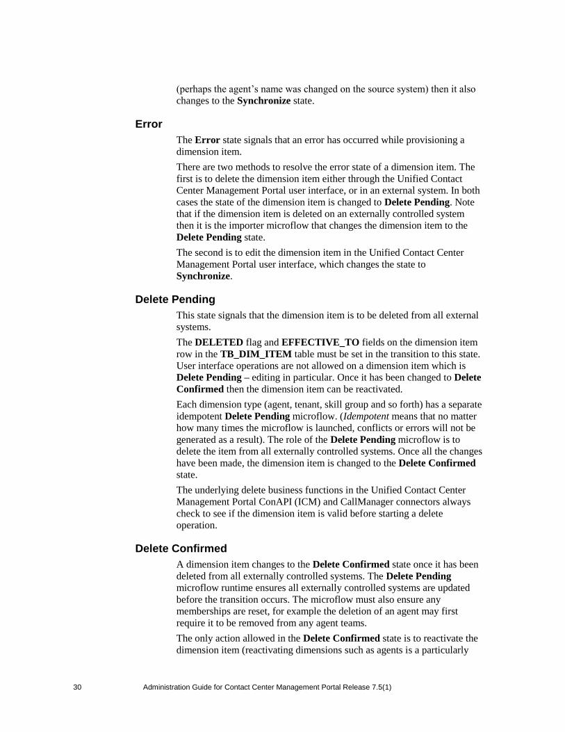
(perhaps the agent‟s name was changed on the source system) then it also
changes to the Synchronize state.
Error
The Error state signals that an error has occurred while provisioning a
dimension item.
There are two methods to resolve the error state of a dimension item. The
first is to delete the dimension item either through the Unified Contact
Center Management Portal user interface, or in an external system. In both
cases the state of the dimension item is changed to Delete Pending. Note
that if the dimension item is deleted on an externally controlled system
then it is the importer microflow that changes the dimension item to the
Delete Pending state.
The second is to edit the dimension item in the Unified Contact Center
Management Portal user interface, which changes the state to
Synchronize.
Delete Pending
This state signals that the dimension item is to be deleted from all external
systems.
The DELETED flag and EFFECTIVE_TO fields on the dimension item
row in the TB_DIM_ITEM table must be set in the transition to this state.
User interface operations are not allowed on a dimension item which is
Delete Pending – editing in particular. Once it has been changed to Delete
Confirmed then the dimension item can be reactivated.
Each dimension type (agent, tenant, skill group and so forth) has a separate
idempotent Delete Pending microflow. (Idempotent means that no matter
how many times the microflow is launched, conflicts or errors will not be
generated as a result). The role of the Delete Pending microflow is to
delete the item from all externally controlled systems. Once all the changes
have been made, the dimension item is changed to the Delete Confirmed
state.
The underlying delete business functions in the Unified Contact Center
Management Portal ConAPI (ICM) and CallManager connectors always
check to see if the dimension item is valid before starting a delete
operation.
Delete Confirmed
A dimension item changes to the Delete Confirmed state once it has been
deleted from all externally controlled systems. The Delete Pending
microflow runtime ensures all externally controlled systems are updated
before the transition occurs. The microflow must also ensure any
memberships are reset, for example the deletion of an agent may first
require it to be removed from any agent teams.
The only action allowed in the Delete Confirmed state is to reactivate the
dimension item (reactivating dimensions such as agents is a particularly

Administration Guide for Contact Center Management Portal Release 7.5(1) 31
31
powerful feature in the user interface) which returns it to the Synchronize
state ready for provisioning. The DELETED flag and EFFECTIVE_TO
fields on the dimension item row in the TB_DIM_ITEM table must also
be reset as part of the reactivate transition.
User Interface
The user interface can only edit dimension items which are in the Error
and Ready states. Dimension items in the Synchronize and Delete
Pending states cannot be edited until the system has processed the
dimension item. There are a number of exceptions to this rule where
effective dates can still be changed in the Synchronize state.
The Error state is particularly important as it catches all the dimension
items that could not be provisioned. The normal use of the Error state is
to hold resources that need to be edited before being provisioned again (by
changing them to the Synchronize state).
Database Codes
The dimension state field in the TB_DIM_ITEM table uses the following
codes:
Code State Description
R Ready Ready is the normal state of a dimension item in
the Unified Contact Center Management Portal
database. It indicates that the dimension item has
been fully provisioned on all externally controlled
systems.
S Synchronize Synchronize is the initial state for all dimension
items created through Unified Contact Center
Management Portal.
P Delete
Pending
The Delete Pending state signals the dimension
item is to be deleted from all externally controlled
systems. The EFFECTIVE_TO and DELETED
fields are also set in the TB_DIM_ITEM table.
D Delete
Confirmed
A dimension item transitions to the Delete
Confirmed state once it has been deleted from all
externally controlled systems.

32 Administration Guide for Contact Center Management Portal Release 7.5(1) 32
E Error The Error state signals an error occurred
provisioning a dimension item.
Memberships
Memberships in the Unified Contact Center Management Portal database
also have effective dating and a status. The Synchronize microflows
ensure that changes to memberships are reflected on any externally
controlled system. The state of a dimension item shows whether it has
been provisioned on all external systems (for example, whether an agent
has been added to an ICM). The state also reflects whether all its
memberships are up to date and fully provisioned. This approach makes it
easy in the user interface to show an item‟s state.
Example Synchronize Microflow
The following steps illustrate the function of a Synchronize microflow:
1. A new tenant is created through the Unified Contact Center
Management Portal user interface. This creates a new row in the
TB_DIM_ITEM table and the derived dimension table (for
tenants this derived table is called TB_DIM_TENANT).
2. The creation of a tenant also triggers the creation of a range of
additional tenant specific entities in the Unified Contact Center
Management Portal database. Examples include a tenant specific
folder, and default tenant user / administrator groups. However,
these additional entities are not central to explanation of this life
cycle.
3. The state of the new tenant is Synchronize.
4. The provisioning system runs periodically. Each dimension type
(agent, tenant, skill group and so forth) has its own Synchronize
microflow. The tenant Synchronize microflow is run by the
Unified Contact Center Management Portal Data Import
component and picks up the new tenant through a SQL query
against the Unified Contact Center Management Portal database.
5. The Synchronize microflow creates a new customer definition on
the required ICM or CICM instance. The customer definition is
created through the Gateway ConAPI connector. The resulting
CustomerDefinitionID primary key allocated by ConAPI is
stored in the TB_DIM_ITEM_PKEY table for that ICM/CICM
instance‟s CLUSTER_RESOURCE identifier.
6. The Synchronize microflow then uses the Unified Contact Center
Management Portal CallManager connector to create a new
Calling Search Space. The microflow also creates a new
dimension in the Unified Contact Center Management Portal
TB_DIM_CALLING_SEARCH_SPACE table. The Calling
Search Space‟s GUID is stored in the TB_DIM_ITEM_PKEY
table for that CallManager‟s CLUSTER_RESOURCE identifier.
Administration Guide for Contact Center Management Portal Release 7.5(1) 33
33
7. Route Partitions are then created in the CallManager. The
microflow ensures new dimensions are added to the
TB_DIM_ROUTE_PARTITION table as necessary. The Calling
Search Space and Route Partitions are joined up in the
CallManager and members are created in the Unified Contact
Center Management Portal membership table:
TB_DIM_ROUTE_PARTITION_
CALLING_SEARCH_SPACE_MEMBER
Note The Portal connectors check to see if a resource already exists on an
externally controlled system before attempting to create it. This is
not always possible but generally avoids duplicate resources after
server crashes. If a resource already exists on an externally
controlled system, then the Gateway connector just looks up and
returns the primary key for that resource.
8. The tenant is now updated by the microflow to the Ready state
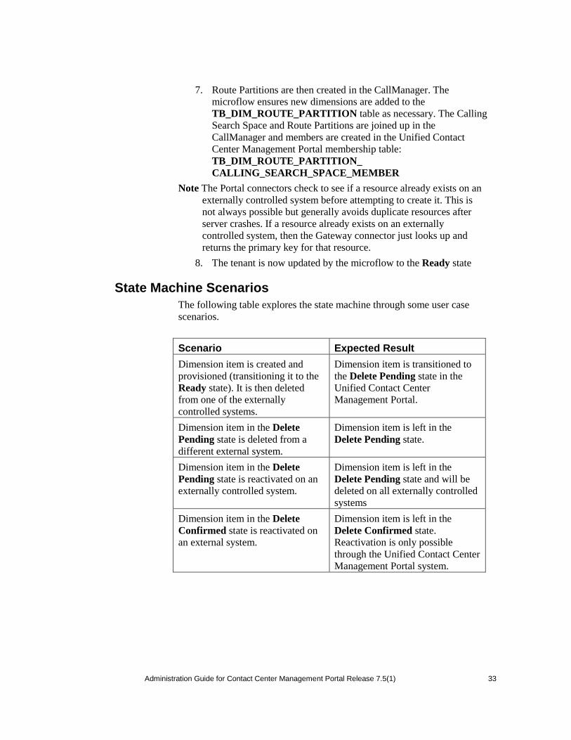
State Machine Scenarios
The following table explores the state machine through some user case
scenarios.
Scenario Expected Result
Dimension item is created and
provisioned (transitioning it to the
Ready state). It is then deleted
from one of the externally
controlled systems.
Dimension item is transitioned to
the Delete Pending state in the
Unified Contact Center
Management Portal.
Dimension item in the Delete
Pending state is deleted from a
different external system.
Dimension item is left in the
Delete Pending state.
Dimension item in the Delete
Pending state is reactivated on an
externally controlled system.
Dimension item is left in the
Delete Pending state and will be
deleted on all externally controlled
systems
Dimension item in the Delete
Confirmed state is reactivated on
an external system.
Dimension item is left in the
Delete Confirmed state.
Reactivation is only possible
through the Unified Contact Center
Management Portal system.

34 Administration Guide for Contact Center Management Portal Release 7.5(1) 34
Scenario Expected Result
Dimension item fails to provision
correctly; perhaps there is a
network connectivity issue
between the Unified Contact
Center Management Portal and the
CallManager.
Dimension item is transitioned to
the Error state. Any systems it
was correctly provisioned on are
reflected in the Unified Contact
Center Management Portal
database. Details of the
provisioning problem are available
in the audit tables.
Dimension item fails to provision
correctly and is then deleted in the
Unified Contact Center
Management Portal system.
Dimension item is transitioned to
the Delete Pending state in the
Unified Contact Center
Management Portal.
Dimension item partially fails to
provision correctly and is then
deleted in an externally controlled
system.
Dimension item is transitioned to
the Delete Pending state in the
Unified Contact Center
Management Portal.
Dimension item in the Error state
is deleted from an externally
controlled system.
Dimension item is transitioned to
the Delete Pending state in the
Unified Contact Center
Management Portal.
The Unified Contact Center
Management Portal server suffers
a total database crash and has to be
restored from backup.
Support technician uses the
Recovery Console to change the
state of all non-deleted dimension
items to Synchronize. The
synchronization may take some
time to run but ensures all
externally controlled systems are
in line with the Unified Contact
Center Management Portal
database. Any dimension items
reactivated since the backup was
taken have to be manually re-
processed.
The Unified Contact Center
Management Portal fact table
importer creates a new dimension
item.
Dimension item is created in the
Synchronize state so that all
externally controlled systems are
brought in line.

Administration Guide for Contact Center Management Portal Release 7.5(1) 35
35
Scenario Expected Result
Just prior to a server crash, a
dimension item was created on an
externally controlled system but
was not updated in the Unified
Contact Center Management Portal
database.
The next time the Synchronize
microflow runs, it brings back the
existing primary key for the
dimension item on the externally
controlled system and updates its
identity in the Unified Contact
Center Management Portal
database table
TB_DIM_ITEM_PKEY.

36 Administration Guide for Contact Center Management Portal Release 7.5(1) 36
7 SYSTEM OPERATIONS
Service Restart Configuration
It is recommended that you configure the services for automatic restart on
failure.
Database Backup and Recovery
The Data Import Server component has a configuration attribute to stop it
processing microflows at a specified time of the day. This allows the Data
Import Server component service to be left running even though
microflows are not being processed. The advantage of this approach is that
health monitoring applications will not raise alerts, such as SNMP traps,
because the service is up and running.
Disabling the Data Import Server can be used to stop importing when SQL
Server backups are taken. It is not recommended to allow backups at the
same time as data is being imported because the database does not have a
consistent state. Database backups are typically automated and run at a
predefined time of the day.

Administration Guide for Contact Center Management Portal Release 7.5(1) 37
37
The Data Import Server is enabled through the EnabledTime attribute in
the Data Import Server service configuration file
(ProvisioningService.exe.config). In the example below, the Data Import
Server processes microflows from 3:00 through to 2:00 (24 hour clock).
This effectively disables the Data Import Server for an hour at 2am. Note
that an import cycle could start just before 2:00 and so may still be running
after 2:00.
<configuration>
<appSettings>
<add key=”EnabledTime” value=”03:00-02:00” />
</appSettings>
</configuration>
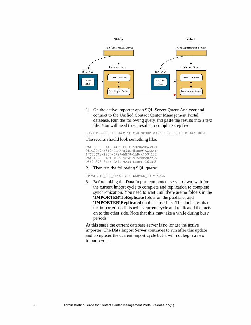
Changing the Active Importer Server
In a distributed deployment of the Unified Contact Center Management
Portal, only one database server can be the active importer. Changing the
active importer to an alternate side is a manual process. Within this set of
steps, the active side is taken to mean the active importer/publisher before
the switch (database A in the diagram below). If you need to check which
machine is the current importer/publisher, the following SQL query returns
the current active importer:
SELECT TOP 1 server.SERVER_NAME
FROM TB_CLU_GROUP grp
JOIN TB_CLU_SERVER server
ON server.SERVER_ID = grp.SERVER_ID
WHERE grp.SERVER_ID IS NOT NULL
38 Administration Guide for Contact Center Management Portal Release 7.5(1) 38
1. On the active importer open SQL Server Query Analyzer and
connect to the Unified Contact Center Management Portal
database. Run the following query and paste the results into a text
file. You will need these results to complete step five.
SELECT GROUP_ID FROM TB_CLU_GROUP WHERE SERVER_ID IS NOT NULL
The results should look something like:
C617D006-8A1B-44F2-BB1B-592BA9FA3958
98DC97B7-E519-41AF-893C-580D94ACEE4F
17C25CA8-E257-4929-ABD8-1AB443534102
F648492C-9AC1-4B89-98AD-9F5FBF20CC35
D562A378-8EBE-4A41-9A34-E8B0F126CBA5
2. Then run the following SQL query:
UPDATE TB_CLU_GROUP SET SERVER_ID = NULL
3. Before taking the Data Import component server down, wait for
the current import cycle to complete and replication to complete
synchronization. You need to wait until there are no folders in the
\IMPORTER\ToReplicate folder on the publisher and
\IMPORTER\Replicated on the subscriber. This indicates that
the importer has finished its current cycle and replicated the facts
on to the other side. Note that this may take a while during busy
periods.
At this stage the current database server is no longer the active
importer. The Data Import Server continues to run after this update
and completes the current import cycle but it will not begin a new
import cycle.

Administration Guide for Contact Center Management Portal Release 7.5(1) 39
39
Note that system stabilization cannot occur unless SQL Server and the
Unified Contact Center Management Portal Replication services are
running correctly. During the stabilization the Data Import Server and
Replication services must both be left running on all servers.
4. Once the system has stabilized, stop the Data Import Server and
the Unified Contact Center Management Portal Replication
services on both sides. Open Replication.xml on the
Publisher/active importer side and comment the following line:
<Subscriber Name=”RemoteSubscriber” Address=”INACTIVE_SERVER_NAME
“ Port=”7500”/>
This file can be found in the Config folder in the Data Import
component server installation. Open the same file on the inactive side
and modify the same line to point to the active server (you may need
to uncomment the line).
<Subscriber Name=”RemoteSubscriber” Address=”ACTIVE_SERVER_NAME”
Port=”7500”/>
5. Again, using SQL Query Analyzer run the following query against
the Unified Contact Center Management Portal database (this can
be done on either database server).
SELECT SERVER_ID,SERVER_NAME FROM TB_CLU_SERVER
The results should look something like:
276824E5-F4BA-4E4C-A565-7F190A365EE1 XWEBTEST
43CA649D-F72B-49E3-B787-AC1966543617 10.10.10.10
3639C7E0-E059-4D04-B1AC-5336840664D2 10.10.10.11
Make a note of the SERVER_ID for the server you wish to set as the
active importer. For example, XWEBTEST has a SERVER_ID of
276824E5-F4BA-4E4C-A565-7F190A365EE1. Using the
GROUP_ID result set shown earlier and the SERVER_ID just
obtained, adapt the following query.

40 Administration Guide for Contact Center Management Portal Release 7.5(1) 40
UPDATE TB_CLU_GROUP
SET SERVER_ID = „<NEW_ACTIVE_IMPORTER_SERVER_ID>‟
WHERE GROUP_ID IN
(„<GROUP_ID_FROM_EARLIER>‟,
„<GROUP_ID_FROM_ EARLIER >‟,
„<GROUP_ID_FROM_ EARLIER >‟,
„<GROUP_ID_FROM_ EARLIER >‟,
„<GROUP_ID_FROM_ EARLIER >‟)
Example using the GROUP_ID result set shown earlier:
UPDATE TB_CLU_GROUP
SET SERVER_ID = „7707C4EF-F58A-412C-9BA8-1A108409B379‟
WHERE GROUP_ID IN
(„C617D006-8A1B-44F2-BB1B-592BA9FA3958‟,
„98DC97B7-E519-41AF-893C-580D94ACEE4F‟,
„17C25CA8-E257-4929-ABD8-1AB443534102‟,
„F648492C-9AC1-4B89-98AD-9F5FBF20CC35‟,
„D562A378-8EBE-4A41-9A34-E8B0F126CBA5‟)
6. Start the Data Import Server service on both sides. Start the
Unified Contact Center Management Portal Replication Subscriber
and Publisher Service on both servers. The system will then start
importing on the other side as normal. Assuming that the SQL
Server and Unified Contact Center Management Portal
Replication services have been configured correctly, the imported
data should start being replicated.
The SQL Server Replication Monitor Manager can help verify this.
The Replicated folder on the original server should also show data
arriving from the new active importer.

Administration Guide for Contact Center Management Portal Release 7.5(1) 41
41
8 CONNECTION MONITORING
The status of the connections used by the Management Portal can be
monitored using the Management Portal‟s Configuration Manager. Open
this by clicking Start > All Programs > Management Portal > Data
Import Server > Configuration Manager. Click the Connection
Manager button and open the Connections tab.
From here, you can edit connection details and attempt to repair failing
connections.
Note The monitor automatically refreshes every few seconds.
Performance Counters
The Management Portal integrates with Windows performance counters
(accessed by running the perfmon command) to provide real time activity
monitoring. Portal appears as up to five separate objects in perfmon, each
with a number of associated performance counters.
The perfmon graph can combine many different performance counters.
Furthermore, perfmon can be configured to trace specific counters at
scheduled times of the day. These performance logs can then be exported
to Excel for further analysis. Perfmon can also connect to remote
computers, if necessary.
For information on how to use and configure perfmon, see the Microsoft
documentation on Performance Logs and Alerts.
You can also monitor performance counters using SysMon (see chapter
10)
CCMP Data Pipeline object
COUNTER MONITORS
Total Cache Reloads Number of times a cache has been
reloaded
Total Database Downloads Total number of database downloads
Total Database Requests Total number of database requests
Total Database Statements Total number of TSQL statements
Total Database Transactions Total number of database transactions
Total Directory Rollbacks Total number of import directories
rolled back
Total Microflow Validation
Errors
Total number of microflows that have
failed validation testing
Total Microflows Run Total number of microflows run
Total Number Imports Total number of imports started
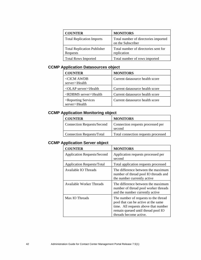
42 Administration Guide for Contact Center Management Portal Release 7.5(1) 42
COUNTER MONITORS
Total Replication Imports Total number of directories imported
on the Subscriber
Total Replication Publisher
Requests
Total number of directories sent for
replication
Total Rows Imported Total number of rows imported
CCMP Application Datasources object
COUNTER MONITORS
<CICM AWDB
server>\Health
Current datasource health score
<OLAP server>\Health Current datasource health score
<RDBMS server>\Health Current datasource health score
<Reporting Services
server>\Health
Current datasource health score
CCMP Application Monitoring object
COUNTER MONITORS
Connection Requests/Second Connection requests processed per
second
Connection Requests/Total Total connection requests processed
CCMP Application Server object
COUNTER MONITORS
Application Requests/Second Application requests processed per
second
Application Requests/Total Total application requests processed
Available IO Threads The difference between the maximum
number of thread pool IO threads and
the number currently active
Available Worker Threads The difference between the maximum
number of thread pool worker threads
and the number currently active
Max IO Threads The number of requests to the thread
pool that can be active at the same
time. All requests above that number
remain queued until thread pool IO
threads become active.

Administration Guide for Contact Center Management Portal Release 7.5(1) 43
43
COUNTER MONITORS
Max Worker Threads The number of requests to the thread
pool that can be active at the same
time. All requests above that number
remain queued until thread pool
worker threads become active.
Min IO Threads The minimum number of idle
asynchronous IO threads currently
maintained by the thread pool.
Min Worker Threads The minimum number of idle worker
threads currently maintained by the
thread pool.
Total Failed Logons Total number of failed logons
Total Failed Logons/Second Total number of failed logons per
second
Total Logon Attempts Total number of logon attempts
Total Logon Attempts/Second Total number of logon attempts per
second
Total Successful Logons Total number of successful logons
Total Successful
Logons/Second
Total number of successful logons
per second
Event Log Alarms
The alarm generator monitors provisioning activity and writes entries to
the event log. The events include provisioning scripts starting and stopping
and requests failing. Rather than writing an entry every time a request
fails, the Portal plugin summarizes every minute. The default reporting
period is one minute; however it can be changed in the minute attribute in
plugins.xml.
An application called evntwin.exe, which ships as part of Windows, is
used to convert the alarms into SNMP traps; see Chapter 9.
44 Administration Guide for Contact Center Management Portal Release 7.5(1) 44
9 SNMP CONFIGURATION The Unified Contact Center Management Portal can be configured to
produce Simple Network Management Protocol (SNMP) traps. SNMP
trapping is a means of monitoring and logging events on the network, such
as faults or errors that impact upon provisioning. SNMP trap
configuration is a three stage process.
Stage 1 - Configure the alarm generator
The alarm generator monitors provisioning activity in the Unified Contact
Center Management Portal and writes events to the event log, including
scripts starting, scripts stopping and requests failing.
Stage 2 - Add alarms to the Windows event log
To view an example of an alarm:
1. Click Start > Administrative Tools > Event Viewer. The Event
Viewer dialog window is displayed
2. Double click on an alarm in the right-hand pane
3. The Event Properties dialog window is displayed in which the alarm
properties are detailed
To add alarms to the Windows event log:
1. Navigate to the Windows folder /evntwin.exe application and run it.
This enables events in the Event Log to be translated out as SNMP
traps.
Note If evntwin.exe cannot be found, you may not have the Simple Network
Management Protocol Windows component installed. Click Start >
Add or Remove Programs > Add/Remove Windows Components and
look at the details for Management and Monitoring Tools to see if this
component is installed. If it is not, check the box to install it and click OK
2. The events are displayed down the right hand side. Select the required
events and add them to the top panel list.
3. If you need to configure trap throttling, click Settings on the main
window. In the Settings dialog window, select the Apply Throttle
radio button in the Trap Throttle panel.
4. Click OK.
Stage 3 - Setup the Windows SNMP service
1. Click Start > Control Panel > Administrative Tools and then
Services. The Services dialog window is displayed.
2. Right click SNMP Service and select Properties from the drop down
list. The SNMP Service Properties dialog window is displayed. This
allows the trap destination and SNMP community to be configured.
3. In the Community Name field, enter the name of the community.
Administration Guide for Contact Center Management Portal Release 7.5(1) 45
45
4. Click Add. A pop up dialog window is displayed. Enter the IP address
of the Trap destination.
5. Click OK.
Alarms Reference
The following sections describe the SNMP traps raised by the Unified
Contact Center Management Portal.
Alarm Service has Started
Meaning
This message simply indicates that from this point onwards the Portal will
log events to the application log.
Occurrence
Either the data import service has just been started or the alarms plugin has
just been added. The alarms plugin is the subsystem responsible for raising
alarms, and it can be loaded dynamically. This event is rare because the
service is not regularly restarted and there is no reason to reload the alarm
service.
Alarm Service has Stopped
Meaning
This message simply indicates that from this point onwards the Portal will
no longer log events to the application log.
Occurrence
Either the data import service has just been stopped or the alarms plugin
has just been unloaded. The alarms plugin is the subsystem responsible for
raising alarms, and it can be loaded dynamically. This event is rare
because the service is not regularly restarted and there is no reason to
reload the alarm service.
Customer Script is Online
Customer script %1 is online.
Meaning
%1 is replaced by the script name. This event indicates that the specified
script has just been brought online.
Occurrence
This alarm is raised when a customer configuration script is added or a
script is restarted after being taken offline for any reason.
Comment
This is an important alarm to monitor because in most situations it
indicates either a recovery from an earlier problem or an attempted
recovery. For example, if connectivity is lost to a customer system, then a

46 Administration Guide for Contact Center Management Portal Release 7.5(1) 46
script may be configured to stop so that a failover script can be used. After
a specified period of time, the script is restarted in order to reconnect to the
customer system.
Use
The actual script affected is referenced within the event text. Therefore, to
use this alarm effectively, the actual text must be scanned in order to
discover the script name.
Customer Script is Offline
Customer script %1 is offline.
Meaning
%1 is replaced by the script name. This event indicates that the specified
script has just been taken offline.
Occurrence
This alarm is raised when a script is removed or a script is stopped for any
reason.
Comment
This is an important alarm to monitor because in most situations it
indicates a problem processing transactions. For example, if connectivity
is lost to a customer system, then a script may be configured to stop so that
a failover script can be used. After a specified period of time, the script is
restarted in order to attempt to reconnect to the system.
Use
The actual script affected is referenced within the event text. Therefore, to
use this alarm effectively, the actual text must be scanned in order to
discover the script name.
Failed Transactions
Provisioning failed %1 transactions for %2 in the last %3 minute(s).
Meaning
%1 is the number of failed transactions; %2 is the name of the script that
relates to the failed transactions; %3 is the period of time over which the
failures occurred. It indicates that the specified script is having problems
processing transactions.
Occurrence
The specified script has failed a number of transactions for some reason.
Comment
This alarm is likely to be raised shortly before the script is taken offline.
The tolerance of a script to errors determines the number of these
messages to be received before a script is taken offline.
Administration Guide for Contact Center Management Portal Release 7.5(1) 47
47
Use
The actual script affected and number of errors is referenced within the
event text. Therefore, to use this alarm effectively, the actual text must be
scanned in order to discover this information.
Timed Out Transactions
Provisioning timed out %1 transactions for %2 in the last %3 minute(s).
Meaning
%1 is the number of timed-out transactions; %2 is the name of the script
with the timed-out transactions; %3 is the period of time over which the
timeouts occurred. It indicates that the specified script is not receiving
responses in a reasonable period of time.
Occurrence
The specified script has not received replies from the connected system in
a reasonable period of time (defined in the script). It will occur in any
situation when no response is received from the customer data system in a
timely manner, or an incorrectly formatted reply is received.
Comment
This alarm is likely to be raised shortly before the script is taken offline.
The tolerance of a script to errors determines the number of these
messages before a script is taken offline.
Use
The actual script affected and number of errors is referenced within the
event text. Therefore, to use this alarm effectively, the actual text must be
scanned in order to discover this information.
Rejected Transactions
Provisioning rejected %1 transactions for %2 in the last %3 minute(s).
Meaning
%1 is the number of timed-out transactions; %2 is the name of the script
with the timed-out transactions; %3 is the period of time over which the
timeouts occurred. It indicates that there was not a script available to
process the transaction when it arrived at the Portal.
Occurrence
A transaction was received for a non-existent script (unlikely). A
transaction was received and the associated script and failover scripts were
all offline.
Comment
This alarm is only likely to be raised during periods where the customer
system is completely unavailable to the Portal. That is to say, both normal
and failover scripts have failed and been taken offline and have not yet
restarted.
48 Administration Guide for Contact Center Management Portal Release 7.5(1) 48
Use
Information regarding the actual script affected and so forth is referenced
within the event text. Therefore, to use this alarm effectively, the actual
text must be scanned in order to discover this information.
Trap Guidelines
The most important alarms are those that check the state of scripts
stopping and starting. Different customer systems have different levels of
reliability and therefore, the associated scripts are given different levels of
error tolerance. Where errors are rare, the tolerance is low or non-existent
and the script is stopped as soon as an error is detected.
In this case it is important to detect the script offline event. In the case
where the backend system is prone to errors/timeouts then the error
tolerance is quite high. It is not that important to pick up the timeout/error
events as these are expected, so it is only when the script is offline that
truly requires monitoring.
MESSAGE IMPORTANCE
Alarm service has started Low - Rarely occurs. Does
not indicate a problem.
Alarm service has stopped Low -See above.
Customer script %1 is online High - Indicates that the
Provisioning Component is
trying to recover from a
problem.
Customer script %1 is offline High - indicates that the
Provisioning Component has
taken action due to too many
transaction errors.
Provisioning failed %1 transactions for
%2 in the last %3 minute(s)
Medium - useful for
checking situation before
script restarts, if more
information is later required.
Provisioning timed out %1
transactions for %2 in the last %3
minute(s)
Medium - see above.
Provisioning rejected %1 transactions
for %2 in the last %3 minute(s)
Medium - see above.
Administration Guide for Contact Center Management Portal Release 7.5(1) 49
49
10 SysMon The System Monitor tool, SysMon, can be used to monitor various aspects
of the system such as CPU usage or the running of specified services, and
alert the system administrator when certain thresholds for performance are
passed.
Installing SysMon
SysMon is installed from the Management Portal installation CD. You
will need to install it on every server you wish to monitor.
SysMon can be run either from a console such as DOS, in which case it
will output to the console, or by doubleclicking the SysMon.exe file, in
which case it will run as a service and output to the debugger. You may
need to start the Management Portal System Monitor service in this case.
The Configuration File
The configuration file is an XML file that tells SysMon what system
activities to monitor, and specifies thresholds and methods for alerting the
system administrator. This file should have the name config.xml, and be
stored in C:\Program Files\Management Portal\SysMon. If SysMon
finds no configuration file when it is run, it will supply a default
configuration file that includes some basic system monitoring but does not
provide email alerts.
Configuration
The first things to be specified in the configuration file are the number of
threads to be used by SysMon, the frequency (in seconds) with which it
should check each item to be monitored, and the loggers (such as
Exony.SysMon.Framework.Loggers.TraceLogger or
Exony.SysMon.Framework.Loggers.ConsoleLogger) to be used. The
ConsoleLogger will only be used when SysMon is run from a console.
Alerts
In the configuration file, a number of alerts are set up. When one of the
items being monitored breaches a set threshold, SysMon enacts the
specified alert.
The alert methods are set up at the beginning of the config file, but the
conditions under which they will be used are set up separately for each
monitor.
To set up an alert, you must specify the name to be used for the alert
within the configuration file and the type of the alert, as well as any
properties for that alert.
Cluster Connection
The cluster connection alert modifies the status of the monitored
connection in the local Portal database. To set up a cluster connection
50 Administration Guide for Contact Center Management Portal Release 7.5(1) 50
alert, specify the alert type to be
Exony.Sysmon.Framework.Alerts.ExonyClusterConnectionAlert. A
cluster connection alert requires the following property:
ExonyDatabase The name of the Portal Database to be updated. If
you accepted the default database name, this will be Portal
To set up an email alert, specify the alert type to be
Exony.SysMon.Framework.Alerts.EmailAlert. An email alert requires
the following properties:
ToAddresses The list of email addresses that messages should be sent
to. Addresses should be separated by semicolons (;)
SMTPServer The SMTP server to be used
FromAddress The email address to be shown in the „from‟ field
ReplyTo SysMon cannot accept incoming email, so the ReplyTo
address should be set with this in mind
Subject The subject of the email. This supports property insertions,
such as the monitor the message concerns
PriorityHigh The email messages sent will be high priority if the
monitor is in the listed states. States should be separated by
semicolons (;). This defaults to Error
PriorityNormal The email messages sent will be normal priority if
the monitor is in the listed states. States should be separated by
semicolons (;). This defaults to Warning
PriorityLow The email messages sent will be low priority if the
monitor is in the listed states. States should be separated by
semicolons (;). This defaults to Ok
Body The message text. This supports property insertions, such as the
message specified by the monitor, or {data} to include any extended
details supplied by the monitor. You can change the locale for the
message by adding a colon and a locale following the message
property. For example, {Message:en-US} would send the US English
message (if set) for a particular monitor. The locale does not have to
be ISO compliant, but must correspond to the locale set for the
message
If necessary, you can set up a different email alert for each locale.
Event Log
To set up an event log alert, specify the alert type to be
Exony.SysMon.Framework.Alerts.EventLogAlert. There are no
properties to be configured for this type of alert.
File
The rolling file alert writes files to a directory, including information on
date/time, the name of the monitor, the result, and the message. It is
recommended that messages for rolling file alerts not make use of the
Administration Guide for Contact Center Management Portal Release 7.5(1) 51
51
{data} property, as this can cause files to become very large. To set up a
rolling file alert, specify the alert type to be
Exony.SysMon.Framework.Alerts.RollingFileAlert. A rolling file alert
requires the following properties:
Directory The location in which the files will be created
DatePattern How the date/time information is to be rendered in the
file. For example, a DatePattern of yyyyMMdd_hh00 would render
15:32:36 on 21 November 2007 into 20071121_1500
FileExtension The extension to be used for the finished file, for
example txt. While a file is being written, its extension will always be
tmp
Interval The number of seconds to pass before creating a new file.
For example, 3600 creates a new file every hour
MaxFileCount The number of files after which the oldest will start
being deleted
MaxDaysToKeep The maximum number of days to keep files for.
Files will be deleted once they have exceeded this age
Monitors
A monitor must be configured for each system item you wish to monitor.
To set up a monitor, you must specify:
name The name to be used within the configuration file for the
monitor
type The type of the monitor. The available types are specified under
the individual monitor sections below
minInterval The normal minimum time (in seconds) between
successive checks of the item being monitored
minWarningInterval The minimum time (in seconds) between
successive checks when the item is in Warning state
minErrorInterval The minimum time (in seconds) between
successive checks when the item is in error state
properties The properties that can be set for each type of monitor are
listed in the individual monitor sections below
messages Lists the messages that are to be sent to the alerts
severity The state (Ok, Warning or Error) that the specified message is
to be used for
locale Sets the different locale messages to be used within each
Severity. This need not be ISO compliant, but must correspond to the
locale set in the alert by which it will be used
alerts Determines which of the alerts previously set up are to be used,
and under what circumstances
name The name of the alert, as specified when the alert was set up

52 Administration Guide for Contact Center Management Portal Release 7.5(1) 52
thresholdError The number of errors that must occur before the alert
is invoked. 1 will invoke the alert each time an error is received
(unless the number of seconds specified in the IntervalError has not
passed since the last invocation), 0 will never invoke the alert. See
also durationThresholdError
thresholdWarning The number of warnings that must occur before
the alert is invoked. 1 will invoke the alert each time a warning is
received (unless the number of seconds specified in the
IntervalWarning has not passed since the last invocation), 0 will never
invoke the alert. See also durationThresholdWarning
thresholdOk The number of checks during which the item is in Ok
state that must occur before the alert is invoked. 1 will invoke the alert
each time an OK is received (unless the number of seconds specified
in the IntervalOk has not passed since the last invocation), 0 will never
invoke the alert. See also durationThresholdOk
intervalOk The interval between successive alerts when the item is in
the OK state
intervalWarning The interval between successive alerts when the
item is in the Warning state
intervalError The interval between successive alerts when the item is
in the Error state
resetWarningsOnOk The number of times an OK state must have
been received before the number of warnings will be reset. By default,
this is 1
resetErrorsOnOk The number of times an OK state must have been
received before the number of errors will be reset. By default, this is 1
durationThresholdWarning The duration (in seconds) the monitor
must have been in a Warning state before the alert is invoked. See
also thresholdWarning
durationThresholdError The duration (in seconds) the monitor must
have been in an Error state before the alert is invoked. See also
thresholdError
durationThresholdOk The duration (in seconds) the monitor must
have been in an OK state before the alert is invoked. See also
thresholdOK
CPU Usage
To set up the CPU usage monitor, specify the monitor type to be
Exony.SysMon.Framework.Monitors.CPUMonitor. A CPU monitor
requires the following properties:
CPU The CPU to monitor. The default is All
Period The number of seconds of data the CPU usage is to be
averaged over. This must be more than 0
WarningThreshold The percentage of CPU usage over which a
warning will be issued
Administration Guide for Contact Center Management Portal Release 7.5(1) 53
53
ErrorThreshold The percentage of CPU usage over which an Error
will be issued. This should be greater than the WarningThreshold
Disk Fragmentation
To set up the disk fragmentation monitor, specify the monitor type to be
Exony.SysMon.Framework.Monitors.DiskFragmentationMonitor. A
disk fragmentation monitor requires the following properties:
Disk The disk to monitor, such as C:
Disk Space
To set up the disk space monitor, specify the monitor type to be
Exony.SysMon.Framework.Monitors.DiskSpaceMonitor. A disk space
monitor requires the following properties:
Disk The disk to monitor, such as C:
WarningThreshold The number of MB free under which a warning
will be issued
ErrorThreshold The number of MB free under which an error will be
issued. This number should be lower than the WarningThreshold
Performance Counters
To set up the performance counter monitor, specify the monitor type to be
Exony.SysMon.Framework.Monitors.PerformanceCounterMonitor.
A performance counter monitor requires the following properties:
Counter The performance counter to monitor
Category The performance object the counter belongs to, such as Data
Gateway
Period The number of seconds the measurement is to be averaged
over. This can be set to 0 for an instantaneous measurement
Trigger Whether the alerts will be invoked by values Above or Below
the thresholds
WarningThreshold The number above or below which (see Trigger)
a warning will be issued
ErrorThreshold The number above or below which (see Trigger) an
error will be issued
Replication
To set up a monitor for SQL Server replication, specify the monitor type to
be Exony.SysMon.Framework.Monitors.ReplicationMonitor. A
replication monitor requires the following properties:
Server The name of the SQL Server to monitor. This will normally be
localhost
DistributionDatabase The name of the distribution database to
monitor
IntegratedSecurity Whether to use Windows authentication (true) or
SQL Server authentication (false)

54 Administration Guide for Contact Center Management Portal Release 7.5(1) 54
Username SQL Server username (such as sa)
Password SQL Server password
Services
To set up a monitor for a specific service, specify the monitor type to be
Exony.SysMon.Framework.Monitors.ServiceMonitor. A service
monitor requires the following properties:
Service The name of the service to monitor
RequiredState Whether the service should be Running or Stopped
SQL Connection
To monitor the state of an SQL Server connection, specify the monitor
type to be
Exony.SysMon.Framework.Monitors.SQLConnectionMonitor. An
SQL connection monitor requires the following properties:
Server The name of the SQL Server to monitor
Database The name of the database to monitor. This will usually be
Portal
TestTable You may optionally specify a table for the monitor to
attempt to select a row from. If this row cannot be selected, an error
will be reported
IntegratedSecurity Whether to use Windows authentication (true) or
SQL Server authentication (false)
Username SQL Server username (such as sa)
Password SQL Server password
SQL Query
To monitor the result of a stored query on an SQL server, specify the
monitor type to be
Exony.SysMon.Framework.Monitors.SQLQueryMonitor. An SQL
query monitor requires the following properties:
ConnectionString The string to use to connect to the SQL server,
such as:
Password=!Password1;User ID=sa;Initial Catalog=Portal;Data
Source=CCMPSERV01
StoredProcedure The name of the stored query to execute. This
query must output an integer
Trigger Whether the alerts will be invoked by values Above or Below
the thresholds
WarningThreshold The number above or below which (see Trigger)
a warning will be issued
ErrorThreshold The number above or below which (see Trigger) an
error will be issued

Administration Guide for Contact Center Management Portal Release 7.5(1) 55
55
11 INDEX
A
Administrator Host ...................................................... 11
Advanced Mode ........................... 14
Agent ............................................ 18
Agent Team .................................. 20
Alarm ............................................ 42
Alarm generator ............................ 41
Alert .............................................. 46 Cluster connection ................................ 46
Email .................................................... 47 Event log .............................................. 47
File ....................................................... 47
Application Component .................. 8
Application Server .................. 26, 27
Argument Exception ..................... 23
Audit ............................................. 24 History .................................................. 24
Audit Report ................................. 24
B
Backup .......................................... 34
Bulk upload .................................. 21
C
Call Error Rate .............................. 39
Call Reject Rate ............................ 39
Call Request Rate ......................... 39
Call Timeout Rate ........................ 39
CallManager ................................. 29
Cluster connection alert ................ 46
Comma Separated Value ... See CSV
ConAPI ......................................... 29
Configuration................................ 46
Configuration Manager .................. 9
Corrupt CSV file .......................... 16
CPU usage monitor....................... 49
CSS ............................................... 23
CSV .............................................. 16
D
Data Import Component .... 8, 26, 27,
34
Database ................................... 8, 26 Backup and Recovery ........................... 34 Codes .................................................... 30
Sides ..................................................... 35
Database Server .............................. 8
Delete Confirmed ................... 29, 30
Delete Pending ........................ 29, 30
Description ...................................16
Dialed Number .............................20
Dimension................... See Resource
Disk fragmentation monitor ..........50
Disk space monitor .......................50
Domain Login Name ....................19
Domain User Name ......................19
E
Edit Filter ......................................24
Email alert ....................................47
Enterprise Name Already Exists ...23
Enterprise Skill Group ..................20
Error .................................. 22, 23, 31 Resource State ...................................... 29
Event log .......................................41 Alert...................................................... 47
Example ........................................22
Excel .............................................16
Exony.Reporting.Application.Server
.exe.config ................................12
F
Failed transactions ........................43
Failover .....................................8, 44
Failure ..................................... 22, 23
File alert ........................................47
Format Exception .........................23
G
Gateway ................. See Provisioning
Component
GROUP_ID ............................ 36, 37
Groups ..........................................15
H
History tab ....................................24
Host administrator ........................11
Host Administrator ...................9, 10
I
ICM ............................................... 9
Idempotent .............................. 28, 29
IIS See Internet Information Services
Manager

56 Administration Guide for Contact Center Management Portal Release 7.5(1) 56
Importance Alarms .................................................. 45
Importer ........................................ 35
Incoming ....................................... 19
Internet Information Services
Manager ............................. 12, 13
IP address ..................................... 42
IPTA ............................................. 20
L
Log ............................................... 40 Application ........................................... 42 Event .................................................... 40
Login ............................................ 11
Login Name Already Exists ......... 23
M
Member attributes ......................... 16
Microflow ............................... 27, 29
Microflows ................................... 31
Monitor ......................................... 48 CPU usage ............................................ 49 Disk fragmentation ............................... 50
Disk space ............................................ 50
Performance counters ........................... 50 Replication............................................ 50
Services ................................................ 51
SQL connection .................................... 51 SQL query ............................................ 51
N
NETBIOS ..................................... 19
No Capacity Left .......................... 23
No Identity Available ................... 23
O
Offline .................................... 43, 44
Online ........................................... 42
Outgoing ....................................... 19
Outstanding Calls...................................................... 39
P
Pass phrase ................................... 18
Password ....................................... 14
Path ............................................... 21
Perfmon ........................................ 39
Perfmon ........................................ 40
Performance counters Monitor ................................................. 50
Performance Counters Scheduling ............................................ 40
Peripheral Number........................ 18
Prefix ............................................10 Create ................................................... 10 Edit ....................................................... 11
Priority ..........................................11
Privileges ......................................14
Provisioning ..............................9, 15
Provisioning Component ........ 39, 41
Publisher .......................................35
R
Ready ...................................... 28, 30
redirect401.htm .............................12
Rejected transactions ....................44
Remote Agent ...............................20
Replication ....................................37 Monitor (SysMon) ................................ 50
Reporting Period ...........................40
Reporting Services ......................... 8
Reports ..........................................24
Required? ......................................16
Resource State ...................................................... 30
Restart ...........................................34
S
Script ............................................42
Security ................. 13, 14, 15, 19, 22
Security Exception ........................23
Security Manager .................... 13, 15
SERVER_ID .................................37
Service ..........................................34
Service Level Threshold ...............20
Service Level Type .......................21
Services.........................................12 Monitor ................................................. 51
Single Sign On ..............................11 Configuring VIM authentication ........... 12 Host administrator ................................ 11
Users ..................................................... 13
Skill Group ...................................20
SNMP Service ..............................41
SNMP Traps ..................... 40, 41, 45
SQL connection monitor ..............51
SQL Exception .............................23
SQL query monitor .......................51
SSO .................... See Single Sign On
State ..............................................27 Resource ............................................... 32
State Trace ....................................18
Supervisor .....................................18
Synchronize ...................... 28, 30, 31 IPCC ....................................................... 9
SysMon .........................................46 Alert...................................................... 46
Configuration ........................................ 46
Administration Guide for Contact Center Management Portal Release 7.5(1) 57
57
Monitor ................................................. 48
System Manager ......... 10, 15, 21, 24
T
Template ....................................... 16
Tenant ............................................. 9 Equipment ............................................ 10
Tenant Administrator................ 9, 13
Tenant User .................................... 9
Throttling ...................................... 41
Timed out ..................................... 44
Timeout ..................... See Timed out
Total Call Errors ........................... 39
Total Call Requests....................... 39
Total Call Timeouts ...................... 39
Total Calls Rejected ..................... 39
Total Processor Starts ................... 39
Total Processor Stops ...................40
Trap Throttling .............................41
U
User Interface ...............................30
User types ...................................... 9
User Variable ................................21
Users .............................................15 Single Sign On ...................................... 13
W
Web Application Server ................ 8
Web Server ........................... 8, 9, 26
Wrap up ........................................19