adjustment of the linac and transport line of nsrl
TRANSCRIPT
ADJUSTMENT OF THE LINAC AND TRANSPORT LINE OF NSRL
Xiaoye He Guicheng Wang Mianling Lu Yuzhu Liu
National Synchrotron Radiation Laboratory, USTC. Hefei, Anhui, P.R.China
1. INTRODUCTION
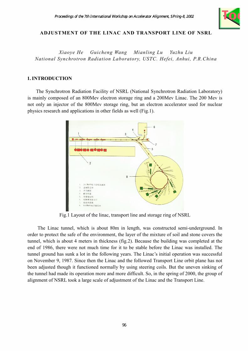
The Synchrotron Radiation Facility of NSRL (National Synchrotron Radiation Laboratory)
is mainly composed of an 800Mev electron storage ring and a 200Mev Linac. The 200 Mev is
not only an injector of the 800Mev storage ring, but an electron accelerator used for nuclear
physics research and applications in other fields as well (Fig.1).
Fig.1 Layout of the linac, transport line and storage ring of NSRL
The Linac tunnel, which is about 80m in length, was constructed semi-underground. In
order to protect the safe of the environment, the layer of the mixture of soil and stone covers the
tunnel, which is about 4 meters in thickness (fig.2). Because the building was completed at the
end of 1986, there were not much time for it to be stable before the Linac was installed. The
tunnel ground has sunk a lot in the following years. The Linac’s initial operation was successful
on November 9, 1987. Since then the Linac and the followed Transport Line orbit plane has not
been adjusted though it functioned normally by using steering coils. But the uneven sinking of
the tunnel had made its operation more and more difficult. So, in the spring of 2000, the group of
alignment of NSRL took a large scale of adjustment of the Linac and the Transport Line.
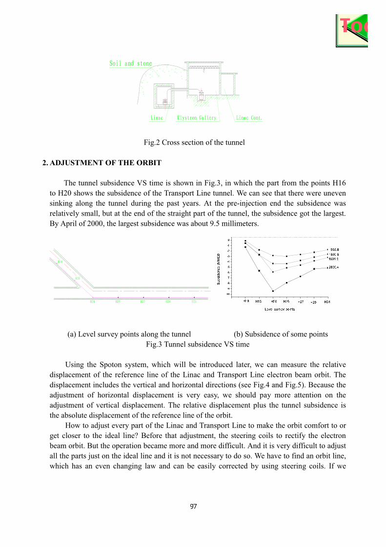
Fig.2 Cross section of the tunnel
2. ADJUSTMENT OF THE ORBIT
The tunnel subsidence VS time is shown in Fig.3, in which the part from the points H16
to H20 shows the subsidence of the Transport Line tunnel. We can see that there were uneven
sinking along the tunnel during the past years. At the pre-injection end the subsidence was
relatively small, but at the end of the straight part of the tunnel, the subsidence got the largest.
By April of 2000, the largest subsidence was about 9.5 millimeters.
(a) Level survey points along the tunnel (b) Subsidence of some points
Fig.3 Tunnel subsidence VS time
Using the Spoton system, which will be introduced later, we can measure the relative
displacement of the reference line of the Linac and Transport Line electron beam orbit. The
displacement includes the vertical and horizontal directions (see Fig.4 and Fig.5). Because the
adjustment of horizontal displacement is very easy, we should pay more attention on the
adjustment of vertical displacement. The relative displacement plus the tunnel subsidence is
the absolute displacement of the reference line of the orbit.
How to adjust every part of the Linac and Transport Line to make the orbit comfort to or
get closer to the ideal line? Before that adjustment, the steering coils to rectify the electron
beam orbit. But the operation became more and more difficult. And it is very difficult to adjust
all the parts just on the ideal line and it is not necessary to do so. We have to find an orbit line,
which has an even changing law and can be easily corrected by using steering coils. If we
0 1 2 3 4 5 6 7
-10
-9
-8
-7
-6
-5
-4
-3
-2
-1
0
2000.4
1991.3
1989.9
1988.8
H31H29H27H25H20H18H16
Subsidence(M
M£©
Level survey points
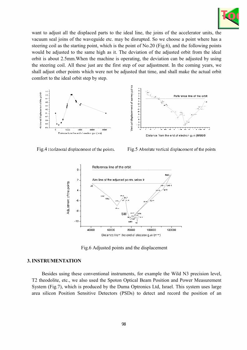
want to adjust all the displaced parts to the ideal line, the joins of the accelerator units, the
vacuum seal joins of the waveguide etc. may be disrupted. So we choose a point where has a
steering coil as the starting point, which is the point of No.20 (Fig.6), and the following points
would be adjusted to the same high as it. The deviation of the adjusted orbit from the ideal
orbit is about 2.5mm.When the machine is operating, the deviation can be adjusted by using
the steering coil. All these just are the first step of our adjustment. In the coming years, we
shall adjust other points which were not be adjusted that time, and shall make the actual orbit
comfort to the ideal orbit step by step.
Fig.4 Horizontal displacement of the points. Fig.5 Absolute vertical displacement of the points
Fig.6 Adjusted points and the displacement
3. INSTRUMENTATION
Besides using these conventional instruments, for example the Wild N3 precision level,
T2 theodolite, etc., we also used the Spoton Optical Beam Position and Power Measurement
System (Fig.7), which is produced by the Duma Optronics Ltd, Israel. This system uses large
area silicon Position Sensitive Detectors (PSDs) to detect and record the position of an
-10000 0 10000 20000 30000 40000 50000 60000 70000 80000 90000 100000 110000 120000 130000
-11
-10
-9
-8
-7
-6
-5
-4
-3
-2
-1
0
1
2
3
4
BM3
QAR11QAR10
QAR9QBR8
QAR7QAR6
QAR5
BM2
QAR4
QAR3
QBR2
BM1
QAL8
QAL7
QAL6
QAL5
QAL4
QAL3
QAL2QAL1
2019
18
1716
1514
1312
1110987
6
54
3
2
1
P8¡¯
JP
Reference line of the orbit
Verticaldisplacementofsurveypoints
Distance from the end of electron gun (MM£©
0 20000 40000 60000 80000
-0.8
-0.6
-0.4
-0.2
0.0
0.2
0.4
0.6
0.8
1.0
1.2
Horizontaldisplacementofthepoints
Distance from the end of electron gun (mm)
40000 60000 80000 100000 120000
-10
-8
-6
-4
-2
0Reference line of the orbit
BM5
QAL12QAL11
P7'
QAR11QAR10
QAR9QAR8
QAR7QAR6
QAR5
BM2
QAR4
QAR3
QBR2
BM1
QAL8
QAL7
QAL6
QAL5
QAL4
QAL3
QAL2
QAL1
SM
Aim line of the adjusted points below it
BM3
20
Adjustm
entofthepoints
Distance from the end of electron gun (mm)

incident light beam. It is computer-card-level devices that plug directly into a personal
computer. Each instrument consists of a detector head with attached cable, a standard half-size
computer card, and control software. Its position measurement range is 8mm diameter circle
maximum, the position resolution is ±1µm, and the position accuracy is ±50µm over 8mm
diameter calibrated area. We use this system, a He-Ne laser light source and a series of Fresnel
lenses (Fig.8) to establish an alignment system. Using this system we measured the relative
displacement of the points on the reference line of the beam orbit.
Fig.7 SpotOn System Fig.8 Fresnel lenses
4.CONCLUSION
We completed the adjustment by the end of July. During the later commission of the
machine, the Linac was operated normally, and the electron beam from it passed through the
transport line more easily and steadily.
5.REFERENCE
[1] Yuanji Pei, Defa Wang, Douhui He, 200 Mev LINAC-INJECTION FOR HESYRL RING, Proceedings of
the International Conference on Synchrotron Radiation Applications,1999,Hefei,China.
[2] Chao Zhang, Sakou Matsui, First Alignment Result of the Storage Ring Magnet Units, Annual
Report,Spring-8,117-118.