adjustable dock instructions - · pdf fileadjustable dock . instructions . reimann &...
TRANSCRIPT
ADJUSTABLE DOCK INSTRUCTIONS
REIMANN & GEORGER CORPORATION MARINE PRODUCTS BUFFALO, NY P/N 6112155 5/01/06
OBSOLETE

TABLE OF CONTENTS
RGC MARINE PRODUCTS PHONE: (716) 895-1156
CHAPTER TITLE PAGE 1 SAFETY ........................................................................................................................................1 1.1 Introduction ....................................................................................................................................1 1.2 Safety Definitions...........................................................................................................................1 1.3 Equipment and Personnel Safety....................................................................................................1
2 SPECIFICATIONS ......................................................................................................................2 2.1 Technical Data................................................................................................................................2 2.2 Optional Equipment........................................................................................................................2
3 INSTALLATION AND SETUP..................................................................................................3 3.1 Configuration Guidelines ...............................................................................................................3 3.2 Pre-Installation Checks...................................................................................................................3 3.3 General Assembly Instructions.......................................................................................................3 3.4 Dock Ramp Assembly ....................................................................................................................4 3.5 Dock Shoreline Leg Frame Support Assembly ..............................................................................5 3.6 Dock Standard Leg Frame Support Assembly ...............................................................................5 3.6.1 Dock Standard Leg Frame Support End Section Assembly ...........................................................5 3.6.2 Dock Standard Leg Frame Support Center Section Assembly.......................................................6 3.7 Dock Support Post Assembly.........................................................................................................7 3.8 Dock Support Post Adjustment ......................................................................................................8 3.9 Dock Standard Leg Frame “L” Mount Configuration Assembly ..................................................8 3.10 Dock Breakwall Support Assembly ...............................................................................................9 3.11 Setting the Dock in the Water .......................................................................................................10 4 INSPECTION AND MAINTENANCE.....................................................................................11 4.1 General Maintenance Rules...........................................................................................................11 4.2 Annual Inspection..........................................................................................................................11 4.3 Storage Procedure..........................................................................................................................11 5 PARTS LISTS..............................................................................................................................12 5.1 Dock Ramp with Aluminum Deck ................................................................................................12 5.2 Dock Ramp with Premium Cedar Deck ........................................................................................12 5.3 Dock Ramp Frame Only................................................................................................................12 5.4 Dock Section with Aluminum Deck..............................................................................................12 5.5 Dock Section with Premium Cedar Deck......................................................................................12 5.6 Dock Leg Frame Shoreline Package .............................................................................................12 5.7 Dock Leg Frame Standard Package...............................................................................................13 5.8 Dock Leg Frame “L” Mount Configuration Standard Package.....................................................13 5.9 Dock Breakwall Support Package .................................................................................................13 5.10 Dock Adjustable Support Package 2-1/2 Foot ..............................................................................13 5.11 Dock Adjustable Support Package 4 Foot.....................................................................................13 5.12 Dock Adjustable Support Package 5-1/2 Foot ..............................................................................13 5.13 Dock Adjustable Support Package 7 Foot.....................................................................................13 5.14 Dock Adjustable Support Package 8-1/2 Foot ..............................................................................14 5.15 Dock Shoreline Support Package Carton of Parts .........................................................................14 5.16 Dock Standard Support Package Carton of Parts ..........................................................................14 5.17 Dock Ramp Bag of Bolts...............................................................................................................14 5.18 Dock Standard Support Package Bag of Bolts ..............................................................................14 5.19 Dock Shoreline Support Package Bag of Bolts .............................................................................14 5.20 Dock Leg Frame Standard Bag of Bolts........................................................................................15 5.21 Dock “L” Mount Configuration Support Package Bag of Bolts ...................................................15 FIGURE DESCRIPTION PAGE

LIST OF FIGURES
RGC MARINE PRODUCTS PHONE: (716) 895-1156
3-1 Typical Adjustable Dock Configurations.........................................................................................3 3-2 Dock Ramp Assembly......................................................................................................................4 3-3 Dock Leg Frame Shoreline Support Assembly................................................................................5 3-4 Dock Leg Frame Standard Support End Section Assembly.............................................................6 3-5 Dock Leg Frame Standard Support Center Section Assembly.........................................................7 3-6 Dock Support Post Assembly...........................................................................................................7 3-7 Dock Support Post Adjustment ........................................................................................................8 3-8 Dock “L” Mount Configuration Assembly ......................................................................................9 3-9 Dock Breakwall Support Assembly ................................................................................................10

1 SAFETY 1.1 INTRODUCTION Your Reimann & Georger Corporation Marine Products Adjustable Dock has been engineered to provide reliable performance, long term economics and safety advantages that no other type can match. However, even a well-designed and well-built dock can malfunction or become hazardous in the hands of an inexperienced and/or untrained user. Therefore, read this manual and related equipment manuals thoroughly before using your dock to provide maximum safety for all personnel, and to get the maximum benefit from your equipment. 1.2 SAFETY DEFINITIONS A safety message alerts you to potential hazards that could hurt you or others or cause property damage. The safety messages or signal words for product safety signs are DANGER, WARNING, and CAUTION. Each safety message is preceded by a safety alert symbol and is defined as follows: DANGER: Indicates an imminently hazardous situation which, if not avoided, will cause death or serious injury. This safety message is limited to the most extreme situations. WARNING: Indicates a potentially hazardous situation which, if not avoided, could result in death or serious injury. CAUTION: Indicates a potentially hazardous situation which, if not avoided, may result in minor or moderate injury. It may also be used to alert against unsafe practices and property-damage-only accidents. 1.3 EQUIPMENT AND PERSONNEL SAFETY 1. Do not assemble or use the dock if any part shows any signs of damage. 2. Do not weld or otherwise modify the dock. Such alterations may weaken the structural integrity of the dock and void
the warranty. 3. Insure that all bolts and nuts are fastened securely prior to using the dock. 4. Insure that all the assembled frames are level and square. 5. All docking accessories must be commercially manufactured and be properly maintained and installed. 6. Do not install or use the dock under the influence of drugs, alcohol, or medication. 7. The dock is intended to support the weight of people only. Do not place any type of watercraft or any heavy
equipment on the dock. 8. Do not leave objects such as boating hardware laying on the dock. These can cause someone to trip and fall into the
water. 9. Do not use the dock during an electrical storm. 10. Do not allow anyone to swim or play under, near or on the dock at any time. 11. At least once a year, inspect the dock thoroughly. 12. Immediately replace any components found to be defective.
1

2 SPECIFICATIONS 2.1 TECHNICAL DATA Dock sections are available in three deck options, powder coated aluminum (ivory), premium cedar wood, or without deck (customer supplies material of choice). Dimensions 4 ft. x 10 ft. Weight with powder-coated decking 116 lbs. Weight with premium cedar decking 131 lbs. Weight without decking 55 lbs. 2.2 OPTIONAL EQUIPMENT The following options are available which enable you to customize your dock system for your particular operation. Installation instructions for items 1 through 6 are included in this manual. Manuals for items 7 through 12 are provided as part of each option kit. 1. Ramp section – Standard dock section with hinge hardware attached to allow for a sloped approach from shore to
dock. 2. Standard leg frame – Infinite screw adjustment for leveling frame over an 18” range. One required for each frame
end joint. Upper bracing included. Available in single units. Example: Two legs for first standard section, one per section there after.)
3. Shoreline leg frame – Bolt adjustments in 1” increments over a 7” range. Supports starting end of dock frame in shallow water. Available in single units.
4. Breakwall support – Attaches starting dock frame to an existing seawall or other structural surface. Available in single unit.
5. L-Mounting configuration – Allows for the attachment of dock sections at right angles to each other. Upper bracing and standard leg frame included. Available in single units
6. Leg support post – Attach to standard leg frame to support dock sections. Available in 18” increments from 2-1/2’ feet to 8-1/2 feet. Lower bracing included. Available in pairs.
7. Ramp treadplate – Attaches to ramp section to allow for a smooth transition from shore to deck surface of ramp section.
8. Cleat – Attaches to deck material to provide a mooring point for watercraft. Available in single units. 9. Ladder – Attaches to deck material to provide access from watercraft or water to dock surface. Available in single
unit. 10. Rubrail corner bumper – Covers upper corner of dock frame to minimize injury or property damage. Can be used on
all outside corners of dock system. Available in single units. 11. Rubrail four-foot bumper – Covers upper edge of dock frame at end of dock system to minimize injury or property
damage. Available in single units. 12. Rubrail ten-foot bumper – Covers upper edge of dock frame side to minimize injury or property damage. Can be
used on side rails of entire dock system. Available in single units.
2

3 INSTALLATION AND SETUP 3.1 CONFIGURATION GUIDELINES 1. Your Reimann & Georger Corporation Adjustable Docks are modular sections that simply bolt together for easy
installation or quick dismantling for winter storage. Heavy-wall support posts support the dock with footplates on the bottom. Support posts have cross braces and diagonal braces for added stability.
2. The deck should be installed where water depths are less than 8 feet and the water level fluctuation is less than 1 foot
during the season. 3. Lay out the general shape of the dock system to fit your needs. Refer to Figure 3-1 for some typical configurations.
Figure 3-1.
Typical Adjustable Dock Configurations 4. Water depths at the dock site must be known, from the lake bottom to normal summer level. If the lake bottom is really
soft, adjust measurement to allow footplate to reach solid surface. 5. Decide on the freeboard height of the deck, which is the distance from the water to deck surface. The deck must be at
least 6 inches higher than the normal wave height. Typical freeboard for a relatively calm lake is 18 inches. 6. Determine the height of each support post (water depth plus desired freeboard) on the layout for configuring the dock
system. All support posts have an adjustment range of 18”. 3.2 PRE-INSTALLATION CHECKS 1. Check the packing list to insure that you have all the parts for the dock configuration you are planning to build. Insure
you have the desired type of deck. 2. If any parts are missing or damaged, contact your local supplier or Reimann & Georger Corporation. Do NOT assemble
the dock if any part shows any signs of damage. 3. Do not weld or otherwise modify any part of the dock assembly. Such alterations may weaken the structural integrity of
the dock and void the warranty. 4. Check water depth every ten feet where each support post will be located. 5. Do not assemble the dock without first reviewing all the safety procedures described in Chapter 1. 3.3 GENERAL ASSEMBLY INSTRUCTIONS 1. The dock sections are the same regardless of configuration. Support packages vary by water depth and end placement.
Support packages, four feet and greater, contain an additional leg brace that self locates near the footplates. 2. Set the dock frame upside down on either soft level ground or sawhorses to install dock support package. 3. This product has been supplied with stainless steel hardware to protect against a harsh marine environment and
provide outstanding performance. Due to the chemistry and surface condition of stainless steel, there is a natural tendency for the hardware to “gall, lock up, or seize” during assembly. To prevent this from occurring, it is highly recommended that the anti-seize supplied in the hardware bag be applied to the mating surfaces of all stainless
3

steel fasteners before assembly. Lubricants containing molybdenum disulfide, graphite, mica or talc may also be used.
CAUTION:DO NOT EXCEED THE MAXIMUM TORQUE RATING ON ALL BOLTS OF 20 FT-LBS.
WARNING:FAILURE TO APPLY A SUITABLE LUBRICANT TO THE MATING SURFACES OFSTAINLESS STEEL THREADED FASTENERS MAY CAUSE GALLING AND/OR SEIZING OFASSEMBLY.
3. Assemble and install one dock section at a time. 3.4 DOCK RAMP ASSEMBLY 1. The dock ramp consists of a standard dock section with the addition of a hinging system to allow a sloped approach onto
the dock. (Refer to Figure 3-2 Step 1). Attach each hinge large half (Q) to the standard dock section using two each 5/16” hex head cap screw (5), 5/16” split lock washer (3), 5/16” hex nut (10), and one backer plate (P). Repeat for other large hinge half. Attach each small hinge half (R) to the ramp dock section using two each 5/16” hex head cap screw (5), 5/16” split lock washer (3), 5/16” hex nut (10) and one backer plate (P). Tighten all four hinge halves securely.
2. It is recommended that final assembly of hinges (joining of dock sections) not be completed until final placement of dock
sections in the water. (Refer to Figure 3-2 Step 2 ). Attach ramp section to standard section by aligning the small hinge halves inside the larger halves. Connect them by using one each 3/8 hex head cap screw (9), split lock washer (1), and hex nut (11). The hex nut should be closest to the outer edge of the dock section for ease of fastening. Repeat for other hinge and tighten both securely.
4
Step 1 Step 2
Figure 3-2. Dock Ramp Assembly
CAUTION:IF THE GROUND IS SOFT, IT MAY BE NECESSARY TO PLACE BLOCKS UNDER THERAMP SECTION TO STOP IT FROM SINKING INTO THE GROUND.
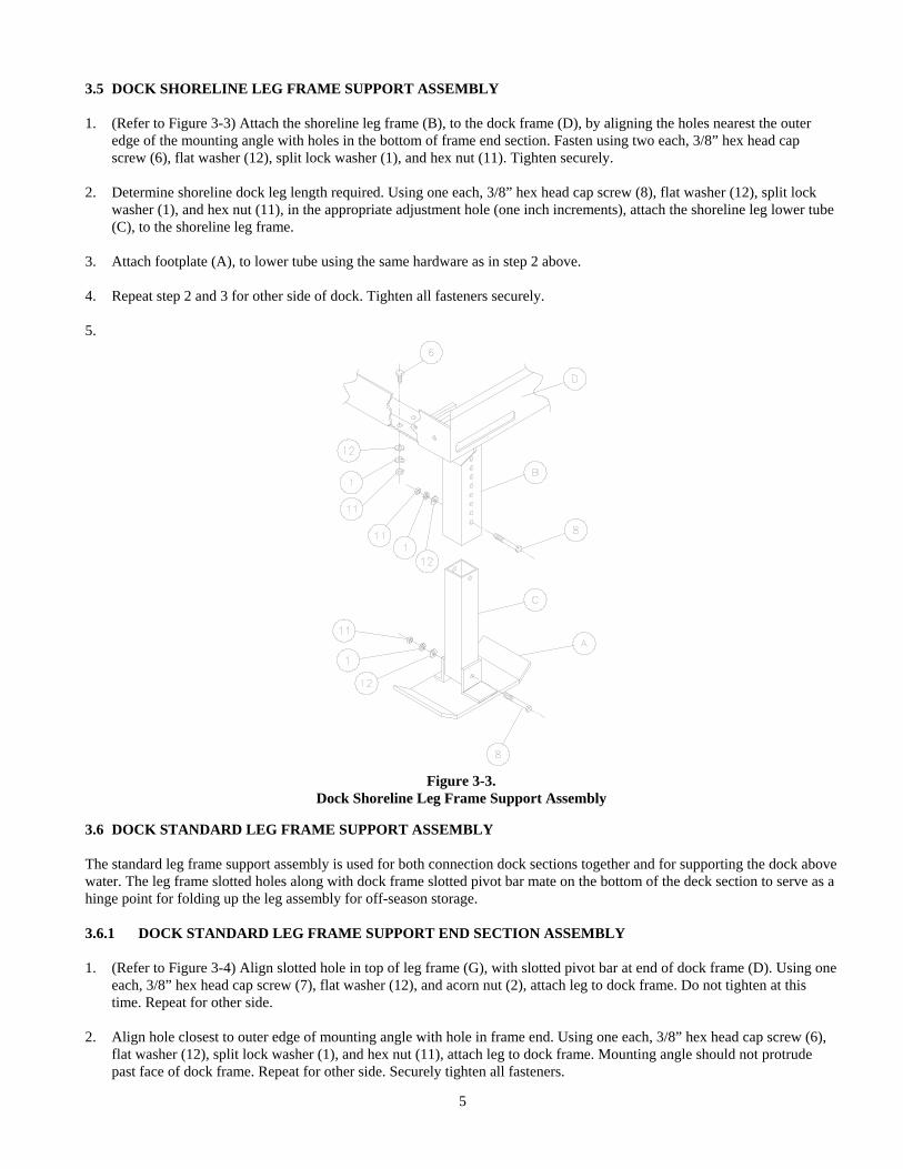
3.5 DOCK SHORELINE LEG FRAME SUPPORT ASSEMBLY 1. (Refer to Figure 3-3) Attach the shoreline leg frame (B), to the dock frame (D), by aligning the holes nearest the outer
edge of the mounting angle with holes in the bottom of frame end section. Fasten using two each, 3/8” hex head cap screw (6), flat washer (12), split lock washer (1), and hex nut (11). Tighten securely.
2. Determine shoreline dock leg length required. Using one each, 3/8” hex head cap screw (8), flat washer (12), split lock
washer (1), and hex nut (11), in the appropriate adjustment hole (one inch increments), attach the shoreline leg lower tube (C), to the shoreline leg frame.
3. Attach footplate (A), to lower tube using the same hardware as in step 2 above. 4. Repeat step 2 and 3 for other side of dock. Tighten all fasteners securely. 5.
Figure 3-3.
Dock Shoreline Leg Frame Support Assembly 3.6 DOCK STANDARD LEG FRAME SUPPORT ASSEMBLY The standard leg frame support assembly is used for both connection dock sections together and for supporting the dock above water. The leg frame slotted holes along with dock frame slotted pivot bar mate on the bottom of the deck section to serve as a hinge point for folding up the leg assembly for off-season storage. 3.6.1 DOCK STANDARD LEG FRAME SUPPORT END SECTION ASSEMBLY 1. (Refer to Figure 3-4) Align slotted hole in top of leg frame (G), with slotted pivot bar at end of dock frame (D). Using one
each, 3/8” hex head cap screw (7), flat washer (12), and acorn nut (2), attach leg to dock frame. Do not tighten at this time. Repeat for other side.
2. Align hole closest to outer edge of mounting angle with hole in frame end. Using one each, 3/8” hex head cap screw (6),
flat washer (12), split lock washer (1), and hex nut (11), attach leg to dock frame. Mounting angle should not protrude past face of dock frame. Repeat for other side. Securely tighten all fasteners.
5

3. Install the dock leg upper brace (F), using two each, 3/8” hex head bolt (6), flat washer (12), split lock washer (1), and hex nut (11). Tighten securely. Repeat for other side.
Figure 3-4. Dock Standard Leg Frame Support End Section Assembly
3.6.2 DOCK STANDARD LEG FRAME SUPPORT CENTER SECTION ASSEMBLY 1. (Refer to Figure 3-5) Align slotted hole in top of leg frame (G), with slotted pivot bar at end of dock frame (D). Using one
each, 3/8” hex head cap screw (7), flat washer (12), and acorn nut (2), attach leg to dock frame. Do not tighten at this time. Repeat for other side.
2. Align hole closest to inner edge of mounting angle with hole in frame end. Using one each, 3/8” hex head cap screw (6),
flat washer (12), split lock washer (1), and hex nut (11), attach leg to dock frame. Mounting angle should protrude past face of dock frame to serve as a mounting surface for adjoining dock sections. (Tee or L-Mounting). Repeat for other side. Securely tighten all fasteners.
3. Install the dock leg upper brace (F), using two each, 3/8” hex head bolt (6), flat washer (12), split lock washer (1), and
hex nut (11). Tighten securely. Repeat for other side.
6

Figure 3-5.
Dock Standard Leg Frame Support Center Section Assembly 3.7 DOCK SUPPORT POST ASSEMBLY 1. ( Refer to Figure 3-6 ) Install the required length dock support posts (I through M), into the leg frame assembly (G). This
is done by inserting the end of the post having the threaded insert into the square opening of the standard leg frame and turning the adjustment nut clockwise six complete turns to fully engage the adjusting screw in the support post. A 1-1/4” wrench is required to turn the adjustment nut.
WARNING:SUPPORT POSTS GREATER THAN 2-1/2 FEET MUST BE BRACED WITH UPPER ANDLOWER LEG BRACING IN TWO DIRECTIONS.
2. Support posts greater than 2-1/2 feet require the use of a dock leg lower brace (E). Install lower brace by sliding the
square tubes over the end of the support posts. 3. Install foot plate (A), onto support post using one each, 3/8” hex head cap screw (8), flat washer (12), lock washer (1),
and hex nut (11). Tighten securely. Repeat for all support posts.
7
Figure 3-6.
Dock Support Post Assembly
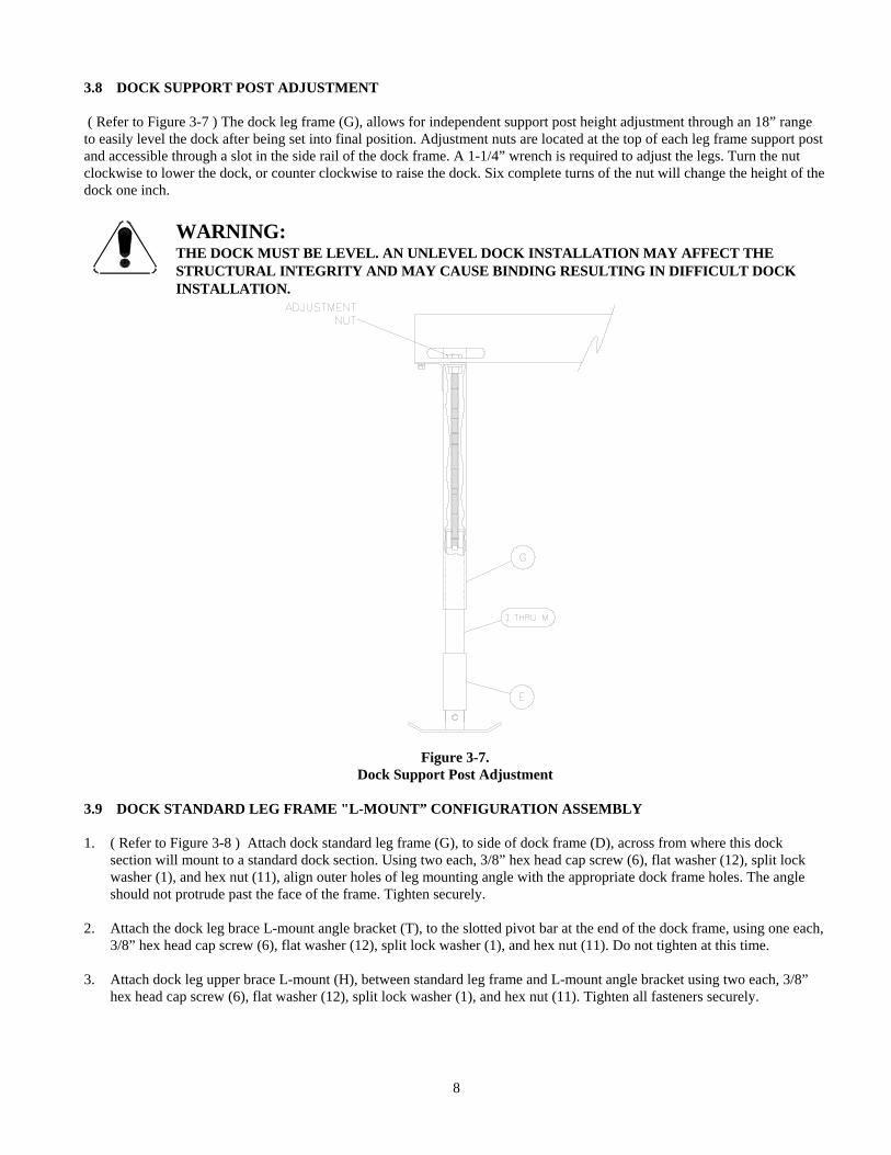
3.8 DOCK SUPPORT POST ADJUSTMENT ( Refer to Figure 3-7 ) The dock leg frame (G), allows for independent support post height adjustment through an 18” range to easily level the dock after being set into final position. Adjustment nuts are located at the top of each leg frame support post and accessible through a slot in the side rail of the dock frame. A 1-1/4” wrench is required to adjust the legs. Turn the nut clockwise to lower the dock, or counter clockwise to raise the dock. Six complete turns of the nut will change the height of the dock one inch.
WARNING:THE DOCK MUST BE LEVEL. AN UNLEVEL DOCK INSTALLATION MAY AFFECT THESTRUCTURAL INTEGRITY AND MAY CAUSE BINDING RESULTING IN DIFFICULT DOCKINSTALLATION.
Figure 3-7.
Dock Support Post Adjustment 3.9 DOCK STANDARD LEG FRAME "L-MOUNT” CONFIGURATION ASSEMBLY 1. ( Refer to Figure 3-8 ) Attach dock standard leg frame (G), to side of dock frame (D), across from where this dock
section will mount to a standard dock section. Using two each, 3/8” hex head cap screw (6), flat washer (12), split lock washer (1), and hex nut (11), align outer holes of leg mounting angle with the appropriate dock frame holes. The angle should not protrude past the face of the frame. Tighten securely.
2. Attach the dock leg brace L-mount angle bracket (T), to the slotted pivot bar at the end of the dock frame, using one each,
3/8” hex head cap screw (6), flat washer (12), split lock washer (1), and hex nut (11). Do not tighten at this time. 3. Attach dock leg upper brace L-mount (H), between standard leg frame and L-mount angle bracket using two each, 3/8”
hex head cap screw (6), flat washer (12), split lock washer (1), and hex nut (11). Tighten all fasteners securely.
8
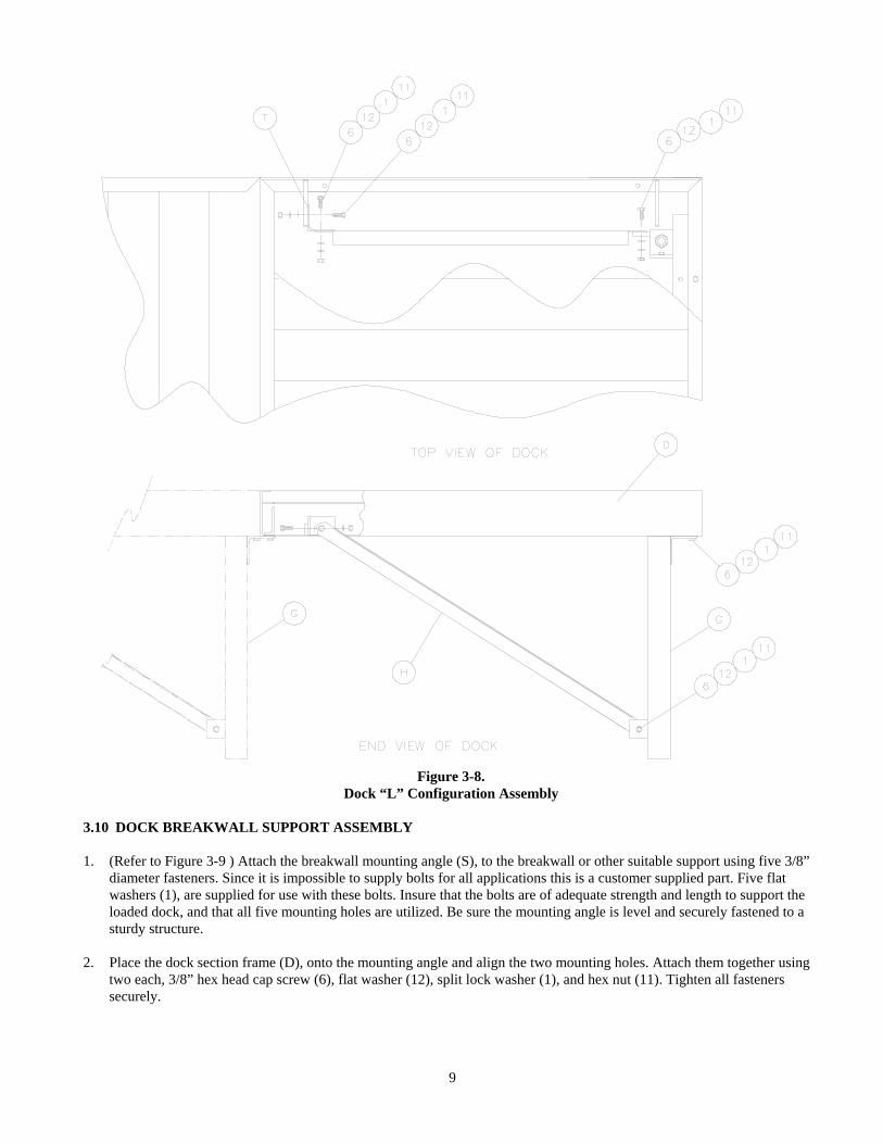
Figure 3-8.
Dock “L” Configuration Assembly 3.10 DOCK BREAKWALL SUPPORT ASSEMBLY 1. (Refer to Figure 3-9 ) Attach the breakwall mounting angle (S), to the breakwall or other suitable support using five 3/8”
diameter fasteners. Since it is impossible to supply bolts for all applications this is a customer supplied part. Five flat washers (1), are supplied for use with these bolts. Insure that the bolts are of adequate strength and length to support the loaded dock, and that all five mounting holes are utilized. Be sure the mounting angle is level and securely fastened to a sturdy structure.
2. Place the dock section frame (D), onto the mounting angle and align the two mounting holes. Attach them together using
two each, 3/8” hex head cap screw (6), flat washer (12), split lock washer (1), and hex nut (11). Tighten all fasteners securely.
9

Figure 3-9.
Dock Breakwall Support Assembly 3.11 SETTING THE DOCK IN THE WATER
WARNING:THE DOCK MUST BE LEVEL. AN UNLEVEL DOCK INSTALLATION MAY AFFECT THESTRUCTURAL INTEGRITY AND MAY CAUSE BINDING RESULTING IN DIFFICULT DOCKINSTALLATION.
1. Set the dock in place one section at a time. 2. Level each section with the desired freeboard (refer back to section 3.1). Level additional sections with previous section. 3. Attach sections together using two each, 3/8” hex head cap screw (6), flat washer (12), split lock washer (1), and hex nut
(11). Tighten all fasteners securely.
CAUTION:DO NOT INSTALL THE DOCK SECTION IN ROUGH WATER CONDITIONS.
10
4 INSPECTION AND MAINTENANCE 4.1 GENERAL MAINTENANCE RULES 1. Do not allow persons other than authorized service personnel to repair this equipment. 2. Do not weld or otherwise modify the dock. Such alterations may weaken the structural integrity of the dock and
invalidate your warranty. 4.2 ANNUAL INSPECTION At least once a year, the dock must be thoroughly inspected.
WARNING:DO NOT ALLOW ANYBODY TO USE THE DOCK UNTIL THIS MAINTENANCE ISCOMPLETED.
1. Ensure all fasteners are tightened securely. 2. Check frame thoroughly for defects. 4.3 STORAGE PROCEDURE 1. Remove the dock before the water freezes. 2. Store the dock away from the edge of the water to prevent ice damage. 3. Disconnect the dock frame end of the upper leg brace and loosen the lower end enough to allow brace to pivot down. 4. Disconnect the individual dock sections from each other by removing the four sets of 3/8” fasteners securing the
standard leg frame to the dock frame. Loosen the dock frame slotted pivot bar fasteners enough to allow the standard leg frame to pivot. The leg assemblies can now be folded up inside the frame section for storage.
5. Ramp sections can be separated by removing the pivot bolt connecting the ramp to the first standard dock section. 6. Disconnect shoreline support leg from dock frame by removing the 3/8” fasteners from the leg-mounting angle.
11
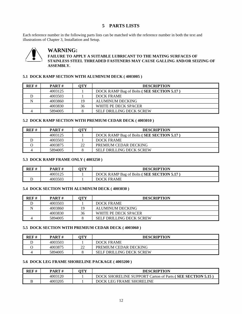
5 PARTS LISTS Each reference number in the following parts lists can be matched with the reference number in both the text and illustrations of Chapter 3, Installation and Setup.
WARNING:FAILURE TO APPLY A SUITABLE LUBRICANT TO THE MATING SURFACES OFSTAINLESS STEEL THREADED FASTENERS MAY CAUSE GALLING AND/OR SEIZING OFASSEMBLY.
5.1 DOCK RAMP SECTION WITH ALUMINUM DECK ( 4003005 )
REF # PART # QTY DESCRIPTION 4003125 1 DOCK RAMP Bag of Bolts ( SEE SECTION 5.17 )
D 4003503 1 DOCK FRAME N 4003860 19 ALUMINUM DECKING 4003830 36 WHITE PE DECK SPACER
4 5894005 8 SELF DRILLING DECK SCREW 5.2 DOCK RAMP SECTION WITH PREMIUM CEDAR DECK ( 4003010 )
REF # PART # QTY DESCRIPTION 4003125 1 DOCK RAMP Bag of Bolts ( SEE SECTION 5.17 )
D 4003503 1 DOCK FRAME O 4003875 22 PREMIUM CEDAR DECKING 4 5894005 8 SELF DRILLING DECK SCREW
5.3 DOCK RAMP FRAME ONLY ( 4003250 )
REF # PART # QTY DESCRIPTION 4003125 1 DOCK RAMP Bag of Bolts ( SEE SECTION 5.17 )
D 4003503 1 DOCK FRAME 5.4 DOCK SECTION WITH ALUMINUM DECK ( 4003030 )
REF # PART # QTY DESCRIPTION D 4003503 1 DOCK FRAME N 4003860 19 ALUMINUM DECKING 4003830 36 WHITE PE DECK SPACER
4 5894005 8 SELF DRILLING DECK SCREW 5.5 DOCK SECTION WITH PREMIUM CEDAR DECK ( 4003060 )
REF # PART # QTY DESCRIPTION D 4003503 1 DOCK FRAME O 4003875 22 PREMIUM CEDAR DECKING 4 5894005 8 SELF DRILLING DECK SCREW
5.6 DOCK LEG FRAME SHORELINE PACKAGE ( 4003200 )
REF # PART # QTY DESCRIPTION 4003120 1 DOCK SHORELINE SUPPORT Carton of Parts ( SEE SECTION 5.15 )
B 4003205 1 DOCK LEG FRAME SHORELINE
12

13
5.7 DOCK LEG FRAME STANDARD PACKAGE ( 4003400 )
REF # PART # QTY DESCRIPTION 4003130 1 DOCK LEG FRAME STANDARD Bag of Bolts ( SEE SECTION 5.20 )
F 4003615 2 DOCK LEG UPPER BRACE STANDARD G 4003625 1 DOCK LEG FRAME STANDARD
5.8 DOCK LEG FRAME L-MOUNT CONFIGURATION STANDARD PACKAGE (4003410 )
REF # PART # QTY DESCRIPTION 4003150 1 DOCK L MOUNT SUPPORT PKG Bag of Bolts ( SEE SECTION 5.21 )
G 4003625 1 DOCK LEG FRAME STANDARD H 4003630 1 DOCK LEG UPPER BRACE L-MOUNT
5.9 DOCK BREAKWALL SUPPORT PACKAGE ( 4003300 )
REF # PART # QTY DESCRIPTION S 4003920 1 DOCK BREAKWALL MOUNTING ANGLE 4003145 1 DOCK BREAKWALL SUPPORT BAG OF BOLTS Consisting of;
1 5806243 7 3/8 SPLIT LOCK WASHER 6 5896247 2 3/8 X 1 HEX HEAD CAP SCREW
11 5896377 2 3/8 HEX NUT 12 5896406 2 3/8 FLAT WASHER
5.10 DOCK ADJUSTABLE SUPPORT PACKAGE 2-1/2 FOOT ( 4003025 )
REF # PART # QTY DESCRIPTION 4003110 1 DOCK STANDARD SUPPORT Carton of Parts ( SEE SECTION 5.16 ) I 4003700 2 DOCK ADJUSTABLE SUPPORT POST 2-1/2 FT
5.11 DOCK ADJUSTABLE SUPPORT PACKAGE 4 FOOT ( 4003040 )
REF # PART # QTY DESCRIPTION 4003110 1 DOCK STANDARD SUPPORT Carton of Parts ( SEE SECTION 5.16 )
E 4003600 1 DOCK LEG LOWER BRACE J 4003705 2 DOCK ADJUSTABLE SUPPORT POST 4 FT
5.12 DOCK ADJUSTABLE SUPPORT PACKAGE 5-1/2 FOOT ( 4003055 )
REF # PART # QTY DESCRIPTION 4003110 1 DOCK STANDARD SUPPORT Carton of Parts ( SEE SECTION 5.16 )
E 4003600 1 DOCK LEG LOWER BRACE K 4003710 2 DOCK ADJUSTABLE SUPPORT POST 5-1/2 FT
5.13 DOCK ADJUSTABLE SUPPORT PACKAGE 7 FOOT ( 4003070 )
REF # PART # QTY DESCRIPTION 4003110 1 DOCK STANDARD SUPPORT Carton of Parts ( SEE SECTION 5.16 )
E 4003600 1 DOCK LEG LOWER BRACE L 4003715 2 DOCK ADJUSTABLE SUPPORT POST 7 FT
14
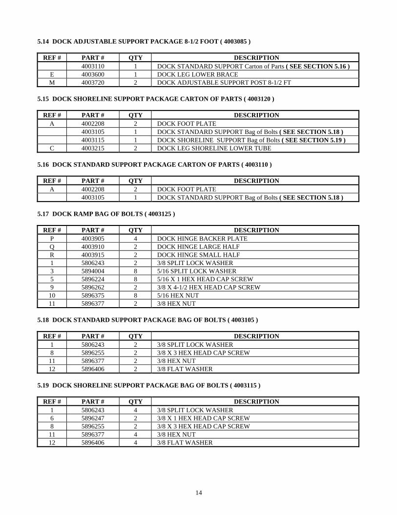
5.14 DOCK ADJUSTABLE SUPPORT PACKAGE 8-1/2 FOOT ( 4003085 )
REF # PART # QTY DESCRIPTION 4003110 1 DOCK STANDARD SUPPORT Carton of Parts ( SEE SECTION 5.16 )
E 4003600 1 DOCK LEG LOWER BRACE M 4003720 2 DOCK ADJUSTABLE SUPPORT POST 8-1/2 FT
5.15 DOCK SHORELINE SUPPORT PACKAGE CARTON OF PARTS ( 4003120 )
REF # PART # QTY DESCRIPTION A 4002208 2 DOCK FOOT PLATE 4003105 1 DOCK STANDARD SUPPORT Bag of Bolts ( SEE SECTION 5.18 ) 4003115 1 DOCK SHORELINE SUPPORT Bag of Bolts ( SEE SECTION 5.19 )
C 4003215 2 DOCK LEG SHORELINE LOWER TUBE 5.16 DOCK STANDARD SUPPORT PACKAGE CARTON OF PARTS ( 4003110 )
REF # PART # QTY DESCRIPTION A 4002208 2 DOCK FOOT PLATE 4003105 1 DOCK STANDARD SUPPORT Bag of Bolts ( SEE SECTION 5.18 )
5.17 DOCK RAMP BAG OF BOLTS ( 4003125 )
REF # PART # QTY DESCRIPTION P 4003905 4 DOCK HINGE BACKER PLATE Q 4003910 2 DOCK HINGE LARGE HALF R 4003915 2 DOCK HINGE SMALL HALF 1 5806243 2 3/8 SPLIT LOCK WASHER 3 5894004 8 5/16 SPLIT LOCK WASHER 5 5896224 8 5/16 X 1 HEX HEAD CAP SCREW 9 5896262 2 3/8 X 4-1/2 HEX HEAD CAP SCREW
10 5896375 8 5/16 HEX NUT 11 5896377 2 3/8 HEX NUT
5.18 DOCK STANDARD SUPPORT PACKAGE BAG OF BOLTS ( 4003105 )
REF # PART # QTY DESCRIPTION 1 5806243 2 3/8 SPLIT LOCK WASHER 8 5896255 2 3/8 X 3 HEX HEAD CAP SCREW
11 5896377 2 3/8 HEX NUT 12 5896406 2 3/8 FLAT WASHER
5.19 DOCK SHORELINE SUPPORT PACKAGE BAG OF BOLTS ( 4003115 )
REF # PART # QTY DESCRIPTION 1 5806243 4 3/8 SPLIT LOCK WASHER 6 5896247 2 3/8 X 1 HEX HEAD CAP SCREW 8 5896255 2 3/8 X 3 HEX HEAD CAP SCREW
11 5896377 4 3/8 HEX NUT 12 5896406 4 3/8 FLAT WASHER

15
5.20 DOCK LEG FRAME STANDARD BAG OF BOLTS ( 4003130 )
REF # PART # QTY DESCRIPTION 1 5806243 8 3/8 SPLIT LOCK WASHER 2 5806266 2 3/8 ACORN NUT 6 5896247 6 3/8 X 1 HEX HEAD CAP SCREW 7 5896248 2 3/8 X 1-1/4 HEX HEAD CAP SCREW
11 5896377 6 3/8 HEX NUT 12 5896406 8 3/8 FLAT WASHER
5.21 DOCK L-MOUNT CONFIGURATION SUPPORT PACKAGE BAG OF BOLTS ( 4003150 )
REF # PART # QTY DESCRIPTION T 4003940 1 DOCK LEG BRACE L-MOUNT ANGLE BRACKET 1 5806243 5 3/8 SPLIT LOCK WASHER 6 5896247 5 3/8 X 1 HEX HEAD CAP SCREW
11 5896377 5 3/8 HEX NUT 12 5896406 5 3/8 FLAT WASHER
6/2003
LIMITED PRODUCT WARRANTY
Reimann & Georger Corporation Marine Products
RGC Marine products, hereafter referred to as the “Manufacturer”, extends this limited warranty to the original purchaser of this product. The original purchaser, hereinafter referred to as the “Buyer”, is defined as the first legal owner of this product other than an authorized distributor or dealer who has bought the product from the Manufacturer for resale to the public. The Buyer must complete and return the Warranty Registration section of the provided Warranty Card to make this limited warranty effective.
CONSUMER PRODUCT PROVISIONS I. ARTICLE I—CONSUMER PRODUCT PROVISIONS: THE FOLLOWING PROVISIONS SHALL BE
APPLICABLE IF THIS PRODUCT IS BEING PURCHASED FOR PERSONAL, FAMILY OR HOUSEHOLD PURPOSES.
THE CONSUMER PRODUCT PROVISIONS CONTAINED IN THIS ARTICLE I SHALL APPLY UNLESS THIS PRODUCT IS BEING PURCHASED SOLELY FOR COMMERCIAL OR INDUSTRIAL USE, IN WHICH EVENT THE PROVISIONS CONTAINED IN ARTICLE II BELOW SHALL APPLY AND THE PROVISIONS CONTAINED IN THIS ARTICLE I SHALL BE INAPPLICABLE.
A. 1-YEAR LIMITED WARRANTY
The Manufacturer warrants to the Buyer that the decking shall be free of defects in material and workmanship for a period of one (1) year from date of original purchase. This limited warranty covers the cost of all parts and labor needed to repair any item that is found to be defective in material and workmanship. This warranty does not cover wear and tear, discoloration (fading), scratches, or dents associated with powder coated decking; nor does this warranty cover splitting, checking, warping, or discoloration associated with wood decking.
B. 15-YEAR LIMITED WARRANTY ON DOCK ALUMINUM FRAME EXTRUSION
The Manufacturer warrants to the Buyer that the frame and extrusions shall be free of defects in material and workmanship for a period of fifteen (15) years from date of original purchase. This limited warranty covers the cost of all parts and labor needed to repair any item that is found to be defective in material and workmanship.
C. MANUFACTURER’S OBLIGATIONS
The Manufacturer’s sole obligation under either of these limited warranties is the replacement or repair, at the Manufacturer’s discretion, of parts found to be defective.
D. NO SPECIAL, INCIDENTAL OR CONSEQUENTIAL DAMAGES
IN NO EVENT SHALL THE MANUFACTURER BE LIABLE TO THE BUYER OR ANY PERSON FOR ANY INDIRECT, SPECIAL, INCIDENTAL, OR CONSEQUENTIAL LOSSES OR DAMAGES CONNECTED WITH THE USE OF THE PRODUCT UNDER WARRANTY. SUCH DAMAGES FOR WHICH THE MANUFACTURER SHALL NOT BE RESPONSIBLE INCLUDE, BUT ARE NOT LIMITED TO, LOST TIME AND CONVENIENCE, LOSS OF USE OF THE PRODUCT, THE COST OF A PRODUCT RENTAL, COSTS OF GASOLINE, TELEPHONE, TRAVEL, OR LODGING, THE LOSS OF PERSONAL OR COMMERCIAL PROPERTY, AND THE LOSS OF REVENUE. Some States do not allow the exclusion or limitation of incidental or consequential damages, so the above limitation or exclusion may not apply to you.
6/2003
E. NO LIABILITY IN EXCESS OF PURCHASE PRICE
IN NO EVENT SHALL THE MANUFACTURER’S OBLIGATIONS UNDER THIS LIMITED WARRANTY EXCEED THE PURCHASE PRICE OF THE PRODUCT.
F. NO EXTENSION OF STATUTE OF LIMITATIONS
ANY REPAIRS PERFORMED UNDER EITHER OF THESE WARRANTIES SHALL NOT IN ANY WAY EXTEND THE ONE-YEAR AND FIFTEEN-YEAR STATUTES OF LIMITATIONS CONTAINED IN THIS LIMITED WARRANTY.
G. PROCEDURE FOR WARRANTY PERFORMANCE
If the product fails to perform to the Manufacturer’s specifications, the Buyer must contact the dealer from whom the product was purchased. The Buyer must provide the dealer with the applicable model and serial numbers, the date of purchase, and the nature of the problem.
H. PREAPPROVAL OF LABOR COSTS
All labor costs related to a dealer’s performance of the warranty obligations under this limited warranty must be pre-approved by Reimann & Georger Corp. Marine Products.
I. NO OTHER EXPRESS WARRANTIES
THE MANUFACTURER IS NOT SUBJECT TO ANY EXPRESS WARRANTIES OTHER THAN THOSE SET FORTH ABOVE.
J. LIMIT ON DURATION OF IMPLIED WARRANTIES
THE DURATION OF ANY IMPLIED WARRANTIES UNDER APPLICABLE STATE LAW RELATING TO THE PURCHASE OF THIS PRODUCT SHALL BE LIMITED TO A PERIOD OF ONE (1) YEAR FROM THE DATE OF PURCHASE. Some States do not allow limitations on how long an implied warranty lasts, so the above limitations may not apply to you.
K. QUESTIONS REGARDING LIMITED WARRANTY
Any questions regarding this limited warranty or the procedure which the consumer should follow in order to obtain performance of any warranty obligation may be addressed to either the dealer from whom this product is purchased or to Reimann & Georger Corp. Marine Products, P.O. Box 681, Buffalo, NY 14240.
L. EXCLUSIONS FROM LIMITED WARRANTY. THIS LIMITED WARRANTY DOES NOT COVER ANY OF THE FOLLOWING:
1. Equipment which has been abused, damaged, used beyond rated capacity, or which is damaged or has defects caused
by repairs or service completed by persons other than authorized service personnel. 2. Costs of repairing damage caused by environmental factors which include, but are not limited to, airborne fallout,
chemicals, tree sap, salt, ocean spray, and water hazards. 3. Damage caused by acts of God which include, but are not limited to, hailstorms, windstorms, tornadoes, sandstorms,
lightning, floods, and earthquakes. 4. Damage under conditions caused by fire or accident, by abuse or negligence, by improper installation, by misuse, by
incorrect operation, by “normal wear and tear”, by improper adjustment or alteration, by alterations not done by the Manufacturer, or by failure of product parts from such alterations.

6/2003
5. Costs of repairing damage caused by poor or improper maintenance, costs of normally scheduled maintenance, or the cost of replacing any parts unless done as the result of a repair covered by your one-year limited warranty.
6. Costs of modifying the product in any way once delivered to the Buyer, even if such modifications were added as a
production change on other products made after the Buyer’s product was built.
M. RIGHT TO MODIFY PRODUCT
The Manufacturer has the right to modify this product at any time without incurring any obligation to make the same or similar modifications on products previously purchased.
N. NO AUTHORITY TO ALTER WARRANTY
No agent, representative, distributor or dealer has any authority to alter the terms of this warranty in any way.
O. SPECIFIC LEGAL RIGHTS
This warranty gives you specific legal rights and you may also have other rights which vary from State to State.

6/2003
COMMERCIAL PRODUCT PROVISIONS
II. ARTICLE II—COMMERCIAL PRODUCT PROVISIONS: THE FOLLOWING PROVISIONS SHALL BE APPLICABLE ONLY IF THIS PRODUCT IS BEING PURCHASED SOLELY FOR COMMERCIAL OR INDUSTRIAL USE. IF THIS PRODUCT IS BEING PURCHASED FOR PERSONAL, FAMILY OR HOUSEHOLD PURPOSES, THE PROVISIONS CONTAINED IN THIS ARTICLE II SHALL NOT BE APPLICABLE AND THE PROVISIONS CONTAINED IN ARTICLE I ABOVE SHALL APPLY.
A. 1-YEAR LIMITED WARRANTY
The Manufacturer warrants to the Buyer that the decking shall be free of defects in material and workmanship for a period of one (1) year from date of original purchase. This limited warranty covers the cost of all parts and labor needed to repair any item that is found to be defective in material and workmanship. This warranty does not cover wear and tear, discoloration (fading), scratches, or dents associated with powder coated decking; nor does this warranty cover splitting, checking, warping, or discoloration associated with wood decking.
B. 5-YEAR LIMITED WARRANTY ON DOCK ALUMINUM FRAME EXTRUSION
The Manufacturer warrants to the Buyer that the frame and extrusions shall be free of defects in material and workmanship for a period of five (5) years from date of original purchase. This limited warranty covers the cost of all parts and labor needed to repair any item that is found to be defective in material and workmanship.
C. MANUFACTURER’S OBLIGATIONS
The Manufacturer’s sole obligation under either of these limited warranties is the replacement or repair, at the Manufacturer’s discretion, of parts found to be defective.
D. NO SPECIAL, INCIDENTAL, OR CONSEQUENTIAL DAMAGES
IN NO EVENT SHALL THE MANUFACTURER BE LIABLE TO THE BUYER OR ANY PERSON FOR ANY INDIRECT, SPECIAL, INCIDENTAL, OR CONSEQUENTIAL LOSSES OR DAMAGES CONNECTED WITH THE USE OF THE PRODUCT UNDER WARRANTY. SUCH DAMAGES FOR WHICH THE MANUFACTURER SHALL NOT BE RESPONSIBLE INCLUDE, BUT ARE NOT LIMITED TO, LOST TIME AND CONVENIENCE, LOSS OF USE OF THE PRODUCT, THE COST OF A PRODUCT RENTAL, COSTS OF GASOLINE, TELEPHONE, TRAVEL, OR LODGING, THE LOSS OF PERSONAL OR COMMERCIAL PROPERTY, AND THE LOSS OF REVENUE.
E. NO LIABILITY IN EXCESS OF PURCHASE PRICE
IN NO EVENT SHALL THE MANUFACTURER’S OBLIGATIONS UNDER THIS LIMITED WARRANTY EXCEED THE PURCHASE PRICE OF THE PRODUCT.
F. NO EXTENSION OF STATUTE OF LIMITATIONS
ANY REPAIRS PERFORMED UNDER EITHER OF THESE WARRANTIES SHALL NOT IN ANY WAY EXTEND THE RESPECTIVE STATUTES OF LIMITATIONS CONTAINED IN THIS LIMITED WARRANTY.
G. WAIVER OF OTHER WARRANTIES
THESE EXPRESS WARRANTIES ARE IN LIEU OF AND EXCLUDE ANY AND ALL OTHER WARRANTIES, EXPRESS OR IMPLIED, INCLUDING, BUT NOT LIMITED TO, THE IMPLIED WARRANTIES OR MERCHANTABILITY AND FITNESS FOR A PARTICULAR PURPOSE.
6/2003
H. PROCEDURE FOR WARRANTY PERFORMANCE
If the product fails to perform to the Manufacturer’s specifications, the Buyer must contact the dealer from whom the product was purchased. The Buyer must provide the dealer with the applicable model and serial numbers, the date of purchase, and the nature of the problem.
I. PREAPPROVAL OF LABOR COSTS
All labor costs related to a dealer’s performance of the warranty obligations under this limited warranty must be pre-approved by Reimann & Georger Corp. Marine Products.
J. EXCLUSIONS FROM WARRANTY. THIS LIMITED WARRANTY DOES NOT COVER ANY OF THE FOLLOWING:
1. Equipment which has been abused, damaged, used beyond rated capacity, or which is damaged or has defects caused
by repairs or service completed by persons other than authorized service personnel. 2. Costs of repairing damage caused by environmental factors which include, but are not limited to, airborne fallout,
chemicals, tree sap, salt, ocean spray, and water hazards. 3. Damage caused by acts of God which include, but are not limited to, hailstorms, windstorms, tornadoes, sandstorms,
lightning, floods, and earthquakes. 4. Damage under conditions caused by fire or accident, by abuse or negligence, by improper installation, by misuse, by
incorrect operation, by “normal wear and tear”, by improper adjustment or alteration, by alterations not done by the Manufacturer, or by failure of product parts from such alterations.
5. Costs of repairing damage caused by poor or improper maintenance, costs of normally scheduled maintenance, or the
cost of replacing any parts unless done as the result of a repair covered by your one-year limited warranty. 6. Costs of modifying the product in any way once delivered to the Buyer, even if such modifications were added as a
production change on other products made after the Buyer’s product was built.
K. RIGHT TO MODIFY PRODUCT
The Manufacturer has the right to modify this product at any time without incurring any obligation to make the same or similar modifications on products previously purchased.
L. NO AUTHORITY TO ALTER WARRANTY
No agent, representative, distributor, or dealer has any authority to alter the terms of this warranty in any way.
M. SPECIFIC LEGAL RIGHTS
This warranty gives you specific legal rights, and you may also have other rights which vary from State to State.