adgs-2100 window manager analysis - formal methods · resources, more architectural layers, more...
TRANSCRIPT

ADGS-2100 Adaptive Display & Guidance System Window Manager Analysis
Michael W. Whalen
John D. Innis Steven P. Miller Lucas G. Wagner
Advanced Technology Center
Rockwell Collins, Inc., 400 Collins Road NE,
Cedar Rapids, IA 52498 USA
November 30, 2005
Abstract Recent advances in modeling languages have made it feasible to formally specify and analyze the behavior of large system components. Synchronous data flow languages, such as Lustre, SCR, and RSML-e are particularly well suited to this task, and commercial versions of these tools such as SCADE and Simulink are growing in popularity among designers of safety critical systems, largely due to their ability to automatically generate code from the models. At the same time, advances in formal analysis tools have made it practical to formally verify important properties of these models to ensure that design defects are identified and corrected early in the lifecycle. This report describes how these tools have been applied to the ADGS-2100 Adaptive Display and Guidance Window Manager being developed by Rockwell Collins Inc. The Window Manager acts as “switchboard” between display applications and physical displays. It is also responsible for ensuring that critical information is displayed to pilots even in the presence of application and hardware failures. In this effort, the majority of the functional behavior of the window manager, with over 16,000 primitive Simulink blocks organized into over 4,000 subsystem instances, was verified against the high-level requirements expressed as 563 temporal logic properties. As a result, 98 errors in the high-level requirements and Simulink models were found and corrected. This work demonstrates how formal methods can be easily and cost-efficiently used to remove defects early in the design cycle.

ii

iii
Table of Contents 1. Introduction 1
2. Background 2
2.1. Overview of the Window Manager Application 2
2.2. Modeling and Verification Tools 4 2.2.1. Simulink....................................................................................................4 2.2.2. SCADE .....................................................................................................4 2.2.3. Reactis.......................................................................................................5 2.2.4. NuSMV.....................................................................................................5 2.2.5. PVS ...........................................................................................................5 2.2.6. SAL...........................................................................................................6
2.3. Translation of Simulink into Analysis Tools 6
3. Analyzing a Large Software Model 8
3.1. Formal Model of a Toy Window Manager 9
3.2. Creating Analysis Partitions 10 3.2.1. Group Related Requirements..................................................................10 3.2.2. Decompose Model into Analysis Subsystems ........................................11 3.2.3. Formalizing Safety Requirements into Properties ..................................13 3.2.4. Factoring System-Level Properties.........................................................15 3.2.5. Determine System Invariants on Subsystem Inputs................................17
3.3. Reducing State: Scaling, Abstraction, and Refactoring 17 3.3.1. Replacing Reals with Integers ................................................................17 3.3.2. Scaling Integer Ranges ...........................................................................18 3.3.3. Refactoring Simulink Models .................................................................18
3.4. Analyzing Subsystems 19 3.4.1. Running RCI/UMN Translators and NuSMV ........................................20 3.4.2. Interpreting Counterexamples.................................................................20 3.4.3. Fixing a Problem Identified by a Counterexample .................................20 3.4.4. Example: The CURSOR_PLACEMENT Subsystem.............................21
4. Analysis Results on the WM Model 25
4.1. Scope of the Effort 26
4.2. Information Collected 26
4.3. Analysis Process 27
4.4. Causes of Errors Found 29
5. Conclusions and Directions for Future Work 30
References 31

iv

1
1. Introduction Recent advances in modeling languages have made it feasible to formally specify and analyze the behavior of large system components. Synchronous data flow languages, such as Esterel [2], Lustre [3], [16], SCR [18], and RSML-e [36] are particularly well suited to this task, and commercial versions of these tools such as SCADE [12] and Simulink [10] are growing in popularity among designers of safety critical systems, largely due to their ability to automatically generate code from the models. At the same time, advances in formal analysis tools have made it practical to formally verify important properties of these models to ensure that design defects are identified and corrected early in the lifecycle [4], [5], [6], [20], [34], [35]. Rockwell Collins is currently designing heads-down and heads-up displays and display management software for next-generation commercial aircraft. An important part of this system is ensuring that data from different displays applications is routed to the correct display, and that critical applications are displayed even in the event of display or computing resource failures. The Window Manager (WM) is responsible for this “switchboard” functionality, routing applications to displays in a flexible way and handling reversion in the case of component failures. In this report, we describe what we believe is the first successful integration of formal analysis into the design cycle of a large-scale critical commercial avionics software application. This effort analyzed the majority of the WM application to a very high degree of rigor and completeness. The only portions of the WM application that were excluded were those that were considered of lower criticality and those that dealt with the hardware-software interface. Our success was predicated on understanding the needs and development processes of the systems and software engineers who were building the WM application. To meet these needs, we had to solve several challenges, including:
• Determining how to map software requirements into formal properties
• Creating translators that would allow commercial modeling tools (such as Simulink [10], [22]) to be quickly and automatically analyzed by different formal analysis tools
• Creating tools that allow analysis results (counterexamples) to be easily understood by the analysts and product engineers
• Defining methods for partitioning the application of interest into subsystems that can be analyzed individually
• Creating a verification process to ensure that: 1) the analysis results are sound, 2) all formal properties are traceable to software requirements, and 3) all requirements of interest are verified through one or more formal properties
• Iterating our verification process with the goal of faster turn-around between development and analysis to create a more efficient and higher quality process.

2
This report is a summary of how the challenges were met and overcome in the course of analyzing the WM application. The remainder of this report is organized as follows. Section 2 provides background information, including an brief overview of a simplified WM and descriptions of the modeling and analysis tools used in the project. Section 2.3 describes how the models are translated into the analysis tools for verification. Section 3 describes the process that was used to perform the analysis. Section 4 discusses how these techniques were applied to the WM and our analysis results. Finally, Section 5 provides concluding remarks and directions for further work.
2. Background This section provides general background information, including a brief overview of a simplified Window Manager and descriptions of the modeling and verification tools used in the project.
2.1. Overview of the Window Manager Application In a modern aircraft, the primary way that aircraft status information is displayed to pilots is through computerized display panels, such as the ones shown in Figure 1. These display panels are designed to replace the dozens of mechanical switches and dials found in earlier aircraft and to present a unified and straightforward interface to critical flight information. The display panels are configurable so as to allow pilots to toggle between several different kinds of information, including navigational maps, aircraft system status, flight checklists, etc. However, some information is considered critically important and should always be displayed.
Figure 1: Example Pilot Display Panels

3
A simplified architecture for such a system is presented in Figure 2. In this figure, two displays provide information to the pilot and copilot. These displays are connected to two redundant computing resources via a high-availability bus. Each computing resource contains several display applications and a display window manager, and is capable of managing both displays. Each display has a “preferred” computing resource that it uses if both resources are available. The user can interact with the displays through the use of a keypad and a trackball (not shown in the architectural figure). The trackball controls a cursor that is visible on the displays. The cursor can move between displays in response to a few different user actions
Figure 2: Simplified Displays Architecture
The Window Manager (WM) determines which applications should be displayed and the location of the cursor on the displays. It also has several responsibilities related to routing information to the displays. First, the WM must update which applications are being displayed in response to user selections of display applications. Second, the WM must handle reversion in case of hardware or application failures. If a display fails, the WM decides which information is most critical and moves this information to the remaining display. Another responsibility has to do with cursor management: some display applications support the cursor while others do not. It is the responsibility of the WM to ensure that the cursor does not appear on a display that contains an application that does not support the cursor. In the event of reversion, the WM must ensure that the cursor is not tasked to a dead display.
PFD EICAS MAP
…PFD EICAS MAP
…
WM WM
Window Manager Display Application

4
The WM is essential to the safe flight of an airplane. If a WM contains logic errors, it is possible that critical flight information will be unavailable to the flight crew. The basic functionality of the WM application is similar to this example. However, the real WM application is much more complex and involves more displays, more computing resources, more architectural layers, more redundancy, and some additional functions that are not found in this example.
2.2. Modeling and Verification Tools This section provides an overview of the modeling and verification tools used in the verification of the WM system. The WM was modeled in Simulink® and analyzed using the NuSMV model checker. Reactis® was used in conjunction with software developed by Rockwell Collins Inc (RCI) and the University of Minnesota to translate the Simulink models into NuSMV. The PVS and SAL tools from SRI International were also investigated as possible analysis tools.
2.2.1. Simulink Simulink® [10] [22], sold by The Mathworks, is a popular platform for the modeling and simulation of dynamic systems. It provides an interactive graphical environment and a customizable set of block libraries that can be used to design, simulate, debug, implement, and test reactive systems. Users assemble a system specification by dragging and dropping blocks onto a pallet and connecting the outputs of one block to the inputs of another block. Blocks can be composed hierarchically from simpler blocks, allowing designers to organize complex system designs. New blocks can be defined by the developer and added to a reusable library. Blocks can also be parameterized. Control logic for representing system states and state transitions can be modeled with the integrated StateFlow® add-on. Simulink and StateFlow are both integrated with the MATLAB® environment, also marketed by The Mathworks, providing access to several additional tools for algorithm development, data analysis, data visualization, and numerical computation. Executable code can generated from a Simulink model using the Real-Time Workshop® add-on. An advantage of Simulink is that it can be simulated with fixed or variable-step solvers, allowing both the control system and the plant model (for example, the airframe) to be modeled within the same framework.
2.2.2. SCADE SCADE [12] is an environment for the development of safety-critical systems similar to Simulink. Originally developed for the design of aircraft systems, similar but separate versions are now marketed by Esterel Technologies for the automotive industry (SCADE Drive™) and the avionics industry (SCADE Suite™). SCADE also provides an interactive graphical environment that allows users to assemble system specifications by dragging and dropping blocks onto a pallet and connecting the outputs of one block to the inputs of another. Control logic for representing system states and state transitions can be modeled with the integrated Safe State Machine© (SSM) add-on. Since the SCADE tools were explicitly created for the development safety-critical software and hardware, SCADE supports only fixed step simulation. For the same reason, the features and blocks supported by SCADE and SSM are restricted to those with an unambiguous mathematical

5
representation. An advantage of SCADE is that its models are translated into the Lustre language, a synchronous data flow language with a precise formal semantics. C source code can be generated from SCADE using the KCG™ code generator which has been qualified as a Level A software development tool in accordance with DO178B. The SCADE Suite also includes a gateway that can import Simulink models and a model checker called Design Verifier.
2.2.3. Reactis Reactis [29] is an automated test-generation and property verification tool for Simulink/StateFlow models developed by Reactive Systems, Inc. It uses random and heuristic search to try to exercise the behavior of models up to a defined level of structural coverage. Reactis supports several different coverage metrics including state, condition, branch, boundary, and MC/DC-level coverage [7]. The result of the search process is a suite of tests which can be used both for structural testing and validation of the model. Reactis allows properties to be specified either using a proprietary Reactis textual notation or as additional StateFlow machines, and will check whether all tests within a test suite satisfy the properties of interest. Because Reactis uses random, rather than exhaustive, search, it can be used to generate tests and attempt to verify properties of very large models that cannot be analyzed by exhaustive search tools such as model checkers. On the other hand, it is not guaranteed that Reactis will generate all tests necessary to reach a level of structural coverage. Furthermore, the generated tests are insufficient to prove that a given property always holds of a model.
2.2.4. NuSMV NuSMV [19] is a symbolic model checker developed as a joint project between the Formal Methods group in the Automated Reasoning System Division at the Instituto Trintino di Cultura (ITC) - Center for Scientific and Technological Research (IRST), the Mechanized Reasoning Groups at the University of Genova and the University of Trento in Italy, and the Model Checking group at Carnegie Mellon University in the United States. NuSMV is a re-implementation and extension of SMV, the first model checker based on Binary Decision Diagrams (BDDs). NuSMV has been designed to be an open architecture for model checking that can be reliably used for the verification of industrial designs, as a core for custom verification tools, as a test bed for formal verification techniques, and applied to other research areas. Properties to be verified in NuSMV are specified using either Computation Tree Logic (CTL) or Linear Time logic (LTL). The advantage of using a model checker such as NuSMV is that it will check all possible combinations of inputs and state to determine if a property is true. We have used the NuSMV model checker to verify properties of models with over 10120 reachable states.
2.2.5. PVS PVS [31] is a theorem prover that has been developed at SRI International's Computer Science Laboratory. In comparison to other widely used verification systems such as HOL and ACL2, the distinguishing characteristic of PVS is that it supports a highly expressive specification language with an interactive theorem prover in which most of the

6
lower-level proof steps are automated. The system consists of a specification language, a parser, a type checker, and an interactive proof checker. The PVS specification language is based on higher-order logic with a richly expressive type system so that a number of semantic errors in a specification can be caught during type checking. The PVS prover consists of a powerful collection of inference steps that can be used to reduce a proof goal to simpler subgoals that can be discharged automatically by the primitive proof steps of the prover. The primitive proof steps involve, among other things, the use of arithmetic and equality decision procedures, automatic rewriting, and BDD-based Boolean simplification.
2.2.6. SAL SAL (Symbolic Analysis Laboratory) [32] is a framework for combining different tools to analyze sequential and concurrent systems. The heart of SAL is a language, developed in collaboration with Stanford, Berkeley, and Verimag, for specifying concurrent systems in a compositional way. The SAL framework contains tools for abstraction, invariant generation, program analysis (such as slicing), theorem proving, and model checking. These tools can be used to separate different analysis concerns and calculate properties (i.e., perform symbolic analysis) of sequential and concurrent systems. SAL includes an explicit-state model checker, a BDD-based symbolic model checker, a SAT-based bounded model checker, and a SAT-based infinite bounded model checker which can symbolically analyze systems containing real numbers. SAL can also be used as an interface to the PVS theorem prover.
2.3. Translation of Simulink into Analysis Tools The translation of Simulink models into NuSMV or other analysis tools requires several steps. However, these are automated and normally completed without great difficulty. The translation process is illustrated in Figure 3.

7
Simulink
StateFlow
SCADE
Safe StateMachines
Lustre
NuSMV
PVS
DesignVerifier
SAL
ICS
SymbolicModel Checker
BoundedModel Checker
Infinite BoundedModel Checker
Reactis
MathWorks
Esterel TechnologiesSRI International
Rockwell Collins/University of Minnesota
Reactis
SimulinkGateway
SimulinkGateway
Figure 3 – Translator Framework
Models are first created using MATLAB Simulink and/or StateFlow. These models then are translated into the Lustre formal specification language using one of two tool chains. In our original tool chain, Simulink/StateFlow models were imported into the SCADE Suite using the Simulink Gateway provided by Esterel Technologies. SCADE Suite is then used to translate the models into Lustre. In a recent update to our tool chain, the Simulink/StateFlow models are imported into Reactis and a Lustre file is generated using a translator developed by Rockwell Collins and the University of Minnesota (hereafter RCI-UMN).1 From Lustre, the models are translated into NuSMV, PVS, or SAL using translators developed by RCI-UMN. The Lustre models can also be imported into Design Verifier, a model checker available in SCADE Suite. The RCI-UMN translators produce highly optimized models most appropriate for the target language. For example, when translating to NuSMV, the translator produces a specification that is difficult for a human to read, but very efficient for proving properties. When translating to PVS, the resulting specification is optimized for readability and to support the development of proofs in PVS. Since the WM model consists primarily of Boolean and enumerated types, it is very efficient to verify properties about the mode logic using a BDD-based model checker such as NuSMV. NuSMV, SAL, PVS, and Design Verifier were also investigated and found to be acceptable alternatives. However, due to the speed and ease of use of NuSMV, the bulk of the WM verification was done using it. A more detailed comparison of the pros and cons of verification using NuSMV and PVS can be found in [25]. 1 For analysis of the DWM, the Reactis tool chain was preferred as Esterel Technologies Simulink Gateway did not yet support release R14 of Simulink, introducing an additional step to convert Simulink R14 models into R13 when using the Simulink Gateway.
8
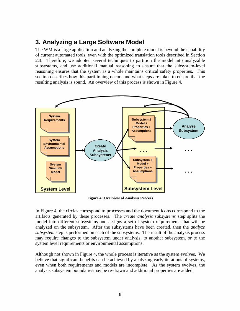
3. Analyzing a Large Software Model The WM is a large application and analyzing the complete model is beyond the capability of current automated tools, even with the optimized translation tools described in Section 2.3. Therefore, we adopted several techniques to partition the model into analyzable subsystems, and use additional manual reasoning to ensure that the subsystem-level reasoning ensures that the system as a whole maintains critical safety properties. This section describes how this partitioning occurs and what steps are taken to ensure that the resulting analysis is sound. An overview of this process is shown in Figure 4.
Subsystem LevelSystem Level
System Requirements
System Requirements
System Simulink
Model
System Simulink
Model
Subsystem kModel +
Properties + Assumptions
Subsystem kModel +
Properties + Assumptions
CreateAnalysis
Subsystems
Subsystem 1Model +
Properties + Assumptions
Subsystem 1Model +
Properties + Assumptions
System Environmental Assumptions
System Environmental Assumptions …
AnalyzeSubsystem
…
…
Figure 4: Overview of Analysis Process
In Figure 4, the circles correspond to processes and the document icons correspond to the artifacts generated by these processes. The create analysis subsystems step splits the model into different subsystems and assigns a set of system requirements that will be analyzed on the subsystem. After the subsystems have been created, then the analyze subsystem step is performed on each of the subsystems. The result of the analysis process may require changes to the subsystem under analysis, to another subsystem, or to the system level requirements or environmental assumptions. Although not shown in Figure 4, the whole process is iterative as the system evolves. We believe that significant benefits can be achieved by analyzing early iterations of systems, even when both requirements and models are incomplete. As the system evolves, the analysis subsystem boundariesmay be re-drawn and additional properties are added.

9
3.1. Formal Model of a Toy Window Manager To illustrate the different steps in the analysis of the WM application without introducing the complexity of the full WM, we have created a toy WM Simulink model that implements some of the requirements described in Section 2.1. To protect proprietary Rockwell Collins data, this example is purposely different from the real WM application, but is sufficiently representative to illustrate many of the concepts and procedures necessary to analyze a much larger model.
Figure 5: Toy WM application
The two subsystems in the application are DU_APPLICATION_SELECTION and CURSOR_PLACEMENT, which manage mapping applications to display units and the location of the cursor, respectively. The inputs to the model are:
• Left/Right DU Available: These inputs describe whether or not the left (right) display unit is available.
• Left/Right Switchbanks: The pilot and copilot have three-way switches to select which application to display on a display unit. The three switch positions are EICAS, PFD, and MAP. Depending on the switch position, one of the left (right) switch bank inputs is true and the other left (right) switch bank inputs are false. When the switch is being turned, it is also possible that all of the switch bank inputs are false.
• Left/Right Cursor Manual Requests: The pilot or copilot can manually request that the display cursor be moved to the left display or the right display using two buttons. In these instances, the left or right manual request inputs are true.
The outputs of the model are:
10
• Left/Right DU Application: These outputs are enumerations: {0 = BLANK, 1 = EICAS, 2 = PFD, 3 = MAP} that describe what is to be displayed on a DU.
• Cursor Location: This output is an enumeration {0 = No Cursor, 1 = Left DU, 2 = Right DU} that describes the location of the display cursor.
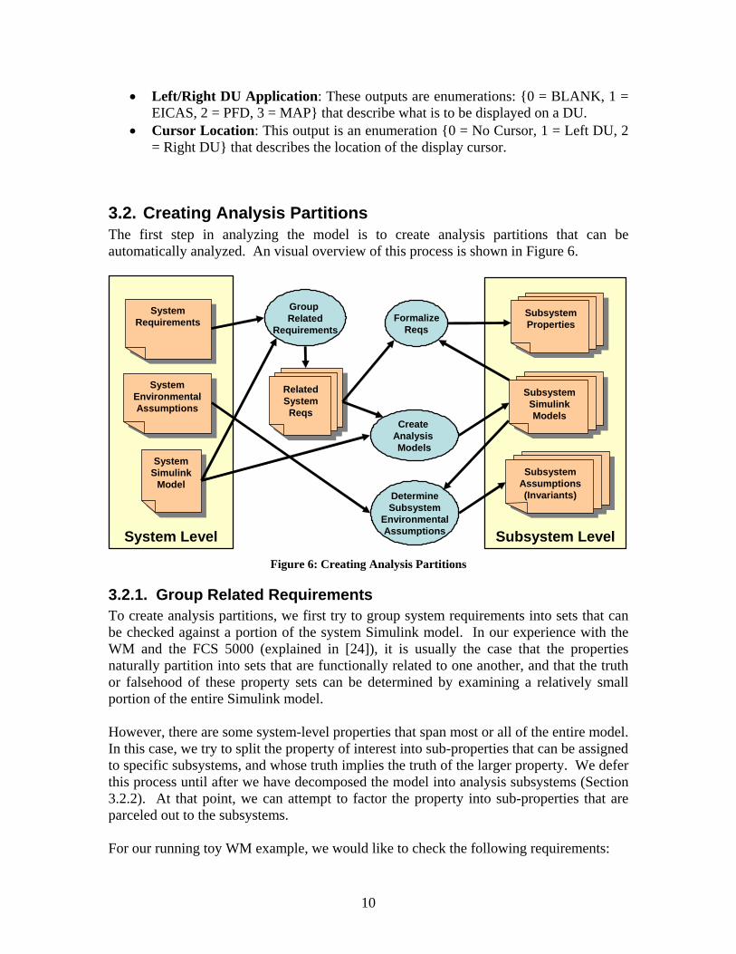
3.2. Creating Analysis Partitions The first step in analyzing the model is to create analysis partitions that can be automatically analyzed. An visual overview of this process is shown in Figure 6.
Subsystem LevelSystem Level
System Requirements
System Requirements
System Simulink
Model
System Simulink
Model
Group Related
Requirements
System Environmental Assumptions
System Environmental Assumptions
Create Analysis Models
Related System Reqs
Related System Reqs
SubsystemSimulinkModels
SubsystemSimulinkModels
FormalizeReqs
SubsystemProperties
SubsystemProperties
DetermineSubsystem
EnvironmentalAssumptions
SubsystemAssumptions(Invariants)
SubsystemAssumptions(Invariants)
Figure 6: Creating Analysis Partitions
3.2.1. Group Related Requirements To create analysis partitions, we first try to group system requirements into sets that can be checked against a portion of the system Simulink model. In our experience with the WM and the FCS 5000 (explained in [24]), it is usually the case that the properties naturally partition into sets that are functionally related to one another, and that the truth or falsehood of these property sets can be determined by examining a relatively small portion of the entire Simulink model. However, there are some system-level properties that span most or all of the entire model. In this case, we try to split the property of interest into sub-properties that can be assigned to specific subsystems, and whose truth implies the truth of the larger property. We defer this process until after we have decomposed the model into analysis subsystems (Section 3.2.2). At that point, we can attempt to factor the property into sub-properties that are parceled out to the subsystems. For our running toy WM example, we would like to check the following requirements:

11
Requirement 1: If a DU is available, then it shall display some application. Requirement 2: If a DU is unavailable, then it shall not attempt to display any application. Requirement 3: The cursor shall not be displayed on a DU that is unavailable. Requirement 4: The cursor shall not be displayed on a DU whose application is not MAP. Requirement 5: When the MAP application is selected for a side, then the cursor shall move to that side. Requirement 6: When the EICAS button is pressed, the display application shall be EICAS. Requirement 7: When the PFD button is pressed, the display application shall be PFD. Requirement 8: When the MAP button is pressed, the display application shall be MAP.
3.2.2. Decompose Model into Analysis Subsystems After grouping the properties, we carve up the system model into reasonably sized analysis models that are sufficient to check one or more of the requirements groups. We would like to make each subsystem small enough (currently < 1050 states) that it is straightforward to analyze using our BDD-based model checking tools. If a subsystem for a set of safety properties is too large to be comfortably analyzed, we use some additional techniques described in Section 3.4.1 to try to reduce it further. An example of this partitioning for the toy WM application of Section 3.1 is shown in Figure 7, in which the heavy lines indicate the boundaries of each analysis partition.

12
3CURSOR_LOCATION
2RIGHT_DU_APPLICATION
1LEFT_DU_APPLICATION
LEFT_DU_AVAILABLE
LEFT_SWITCHBANK_EICAS
LEFT_SWITCHBANK_PFD
LEFT_SWITCHBANK_MAP
RIGHT_DU_AVAILABLE
RIGHT_SWITCHBANK_EICAS
RIGHT_SWITCHBANK_PFD
RIGHT_SWITCHBANK_MAP
LEFT_DU_APPLICATION
RIGHT_DU_APPLICATION
DU_APPLICATION_SELECTION
LEFT_DU_APPLICATION
RIGHT_DU_APPLICATION
LEFT_MANUAL_REQUEST
RIGHT_MANUAL_REQUEST
CURSOR_LOCATION
CURSOR_PLACEMENT
10RIGHT_MANUAL_REQUEST
9LEFT_MANUAL_REQUEST
8RIGHT_SWITCHBANK_MAP
7RIGHT_SWITCHBANK_PFD
6RIGHT_SWITCHBANK_EICAS
5LEFT_SWITCHBANK_MAP
4LEFT_SWITCHBANK_PFD
3LEFT_SWITCHBANK_EICAS
2RIGHT_DU_AVAILABLE
1LEFT_DU_AVAILABLE
Figure 7: Toy WM application with subsystem boundaries
In the Toy Window Manager, the set of safety properties to be verified are clustered around the two areas of the model. The first set determines selection of an application to display on each display unit (requirements 1, 2, 6, 7, and 8). This set can be analyzed by examining the upper partition of the model, shown in solid blue. The second set determines where to locate the cursor (requirements 4 and 5). This set can be analyzed by examining the lower partition of the model shown in dashed red. The remaining requirement (requirement 3) spans both subsystems and will have to be split into requirements over the subsystems that together entail the original requirement. We will describe how this is accomplished during formalization of requirements (Sections 3.2.3 and 3.2.4). If the original Simulink system model is properly architected, then these analysis models can be generated with very little effort. In Simulink, it is possible to split an application into libraries that can be loaded into several models. As long as the subsystems to be analyzed are contained in libraries, we can very easily create new top-level models containing the subsystems. Then, as long as the subsystem interfaces remain stable, the libraries can evolve without touching the analysis models.

13
3.2.3. Formalizing Safety Requirements into Properties The next step in analyzing the model involves formalizing the functional and safety requirements into CTL properties. For a synchronous system where the requirements are specified as “shall” statements over system inputs and outputs, this process is relatively straightforward2. In [24], [25], and [35], we described the process of translating these informal statements into safety properties in more detail. The system requirements document is not the only source of properties to be analyzed. Properties also emerge from discussions with developers about the functionality of different subsystems, or even from a careful review of a particular implementation detail of the Simulink model. In some cases, these properties can be thought of as validity checks for particular implementation choices, but on occasion they lead to additions to the system requirements document. For example, in the Toy WM model, the LEFT_DU_APPLICATION and RIGHT_DU_APPLICATION outputs are implemented as integers, but they are supposed to act like enumerations. Therefore, they should always be in the range 0 (BLANK) to 3 (MAP). Otherwise, the output is out-of-range. This aspect of the implementation can be easily formalized and checked. Most of the requirements in the WM (and all of the Toy WM requirements) fall into two CTL templates. The first is simply a constraint that must be maintained by all reachable states. For example, the requirement:
If a DU is available, then it shall display some application can be translated into two CTL properties (one for each side) as follows:
AG(LEFT_DU_AVAILABLE -> LEFT_DU_APPLICATION != BLANK ) AG(RIGHT_DU_AVAILABLE -> RIGHT_DU_APPLICATION != BLANK ) The AG operator states that the property must hold for all globally reachable states, and -> is the implication operator, The formal property for the left side can be paraphrased:
In all reachable states, if the left DU is available, then its application shall not be blank.
The second template is a constraint over a reachable system state and all possible next states. This template is required when we are interested in observing the behavior of the system at the moment some change occurs. For example, in the requirement:
When the MAP application is selected for a side, then the cursor shall move to that side.
2 Occasionally, internal variables within the analysis model are used to specify properties, but this is discouraged, because in this case the correctness of the analysis hinges on whether the internal variable was correctly computed. If internal variables are used, then additional properties must be developed and specified to ensure that the internal variable is correctly computed.

14
we are interested in the moment when the MAP application is selected.. This requirement can be translated into CTL (for the left side) as:
AG( LEFT_DU_APPLICATION != MAP -> AX( LEFT_DU_APPLICATION = MAP ->
CURSOR_LOCATION = LEFT_DU ) )
where the AX operator encloses a property that must hold in all next states. Given these operator definitions, the property can be paraphrased:
In any state in which LEFT_DU_APPLICATION is not equal to MAP, then in any next state in which LEFT_DU_APPLICATION is equal to MAP, the CURSOR_LOCATION must be LEFT_DU.
In order to define ‘selection’, we have to describe the change in state of LEFT_DU_APPLICATION. The AX operator provides this ability. Given the system inputs described in Figure 5, we can formalize the Toy WM requirements in CTL as shown in table Table 1. Most of the properties in the full WM follow these CTL forms, but occasionally additional CTL operators are used. For a complete introduction to CTL and LTL, see [9].

15
Requirement: CTL Properties: 1: If a DU is available,
then it shall display some application
AG(LEFT_DU_AVAILABLE -> LEFT_DU_APPLICATION != BLANK ) AG(RIGHT_DU_AVAILABLE -> RIGHT_DU_APPLICATION != BLANK )
2: If a DU is unavailable, then it shall not attempt
to display any application
AG( !LEFT_DU_AVAILABLE -> LEFT_DU_APPLICATION = BLANK ) AG( !RIGHT_DU_AVAILABLE -> RIGHT_DU_APPLICATION = BLANK )
3: The cursor will not be displayed on a DU that is
unavailable
AG( !LEFT_DU_AVAILABLE -> CURSOR_LOCATION != LEFT_DU ) AG( !RIGHT_DU_AVAILABLE -> CURSOR_LOCATION != RIGHT_DU )
4. The cursor shall not be displayed on a DU
whose application is not MAP
AG( LEFT_DU_APPLICATION != MAP -> CURSOR_LOCATION != LEFT_DU)) AG(RIGHT_DU_APPLICATION != MAP -> CURSOR_LOCATION != RIGHT_DU)
5. When the MAP application is selected for
a side, then the cursor shall move to that side
AG( LEFT_DU_APPLICATION != MAP -> AX( LEFT_DU_APPLICATION = MAP -> CURSOR_LOCATION = LEFT_DU ) ) AG( RIGHT_DU_APPLICATION != MAP -> AX( RIGHT_DU_APPLICATION = MAP -> CURSOR_LOCATION = RIGHT_DU ) )
6. When the EICAS button is pressed
(SELECT_EICAS), EICAS shall be the display application
AG( LEFT_SELECT_EICAS -> LEFT_DU_APPLICATION = EICAS ) AG( RIGHT_SELECT_EICAS -> RIGHT_DU_APPLICATION = EICAS )
7. When the PFD button is pressed
(SELECT_PFD), PFD shall be the display
application
AG( LEFT_SELECT_PFD -> LEFT_DU_APPLICATION = PFD ) AG( RIGHT_SELECT_PFD -> RIGHT_DU_APPLICATION = PFD )
8. When the MAP button is pressed
(SELECT_MAP), MAP shall be the display
application
AG( LEFT_SELECT_MAP -> LEFT_DU_APPLICATION = MAP ) AG( RIGHT_SELECT_MAP -> RIGHT_DU_APPLICATION = MAP )
Each DU_APPLICATION
variable shall always be assigned a value between
0 and 3.
AG( LEFT_DU_APPLICATION <= 3 & LEFT_DU_APPLICATION >= 0 ) AG( RIGHT_DU_APPLICATION <= 3 & RIGHT_DU_APPLICATION >= 0 )
Table 1 : Formalizing Written Requirements
3.2.4. Factoring System-Level Properties There are some system-level properties that span most or all of the model. In this case, we try to split the property of interest into sub-properties that can be assigned to specific subsystems and whose truth imply the truth of the larger property. The process for factoring system level properties is shown in Figure 8.

16
System Requirement
System Requirement
FormalizeProperty
System PropertySystem Property
Determine Necessary
Subsystems
SubsystemSimulinkModels
SubsystemSimulinkModels
NecessarySimulink
Subsystems
NecessarySimulink
Subsystems
CreateSufficient
SubsystemProperties:
Requires ManualProof
SubsystemProperties
SubsystemProperties
Analyze SubsystemProperties
Subsystem Properties
Verified
Subsystem Properties
Verified
Figure 8: Factoring System-Level Properties
This process is fairly straightforward, but requires some creativity when splitting the property into parts that can be analyzed on the analysis subsystems. Furthermore, it is the responsibility of the analyst to manually prove whether these subsystem properties entail the system-wide property. For example, requirement #3 states that the cursor will not be displayed on a display unit that is unavailable. Formally, this is expressed:
AG( !LEFT_DU_AVAILABLE -> CURSOR_LOCATION != LEFT_DU ) AG( !RIGHT_DU_AVAILABLE -> CURSOR_LOCATION != RIGHT_DU )
We will examine the left side property; since the system is symmetric, this also proves the property for the right side. The property cannot be checked by examining the application placement subsystem as it does not describe the cursor location, and also cannot be checked by the cursor placement subsystem, since it does not contain inputs determining DU availability. However, it is possible to determine the validity of the property by examining the properties for requirements two and four. Given the validity of subsystem properties two and four:
AG( !LEFT_DU_AVAILABLE -> LEFT_DU_APPLICATION = BLANK ) (Req. 2) AG( LEFT_DU_APPLICATION != MAP -> CURSOR_LOCATION != LEFT_DU)) (Req 4.)
and an additional (trivial) property:
SPEC AG( LEFT_DU_APPLICATION = BLANK -> LEFT_DU_APPLICATION != MAP )

17
we can immediately determine
AG( !LEFT_DU_AVAILABLE -> CURSOR_LOCATION != LEFT_DU )
The case for the right side property is symmetric.
3.2.5. Determine System Invariants on Subsystem Inputs It is often not possible to verify interesting safety properties on a large model in a completely unconstrained environment. Instead, the correctness of the controller depends on certain environmental assumptions about its environment. As part of the analysis process, we examine the environmental assumptions in the requirements document to create constraints on the possible values of inputs into the system. The constraints on inputs are specified as invariants in NuSMV, which restrict the states that will be visited during the model checking process. In this step, we determine and formalize the applicable environmental assumptions for each subsystem as NuSMV invariants. For reasons that are explained in the following two paragraphs, we initially use these invariants as tools to explain counterexamples rather than to restrict analysis, and we leave them commented out. Although invariants are necessary to prove “interesting” properties over subsystems, they are also dangerous to the soundness and applicability of the analysis. If conflicting invariants are specified, then there are no states that satisfy the invariants, so all properties are trivially true. Similarly, if invariants restrict the set of allowed inputs so that it is a subset of the possible inputs to the real system, then our analysis will be incomplete. Finally, just because constraints are specified in the requirements document does not mean that other systems will actually obey these constraints. Therefore, although we formalize the invariants in this step we do not use them in our initial model checking analysis. If the initial subsystem analyses return counterexamples, we analyze the counterexamples to see whether they are due to violations of our invariants or due to incorrect behavior within the model. Even if counterexamples are due to invariant violations, we prefer to strengthen the model behavior, when possible, to deal with abnormal environments rather than use system invariants. If it is determined that there is no good way to handle abnormal environments within the model, then we finally begin to use the invariants derived from the environmental assumptions.
3.3. Reducing State: Scaling, Abstraction, and Refactoring The primary limiting factor when using the model checker is the size of the state space. In this section, we describe strategies to reduce the size of model state spaces that were used in the WM analysis.
3.3.1. Replacing Reals with Integers Our current model-checking tools are unable to reason about real numbers. Fortunately, real-valued variables are not used in a substantive way for the WM application, and we have developed simple techniques to replace reals with integer subranges.

18
We have used a simplified version of domain reduction abstraction [8], which attempts to reduce the domain of some variable while preserving the interesting traces, i.e., the ones that can lead to a counterexample, of system behavior. The idea is to preserve enough values such that all conditions involving real numbers will be completely exercised. In the WM, real numbers are only used in addition and subtraction by constants and comparisons between real-valued variables and constants. Therefore, it is very straightforward to preserve the behavior of these variables using a scaled range of integers. The range of the integer is determined by examining all of the relational comparisons and arithmetic operations in the model and the formal properties that involve the variable. For example, one real-valued variable in the “full” WM is the vertical position of the cursor on a display, so that when the cursor is transferred to another display, it is at the same vertical position. However, this position is never changed by the WM, and is only used to notify the “new” display when a cursor transfer occurs. Therefore, we can effectively replace the real number with a constant integer.
3.3.2. Scaling Integer Ranges In order to efficiently model-check a specification, we would like to determine the minimal range necessary to represent the behavior of each variable in the model. This is because the performance of BDD-based model checkers is directly correlated to the ranges of the variables in the model. The SMV translation tools currently allow the user to specify the default range of all integer variables within the model, which allow a gross level of control over ranges. However, when models become large, fine-tuning the integer subranges on a variable-by-variable can have a dramatic impact on model-checking performance. Currently, this is done manually by editing the generated SMV model. In the future, we plan to add support for automatically deriving bounds for variables within the model to the translation tools.
3.3.3. Refactoring Simulink Models Design choices that lead to code-bloat or poorly cohesive systems also affect the performance of the model checker. A rule of thumb is that the larger the number of blocks within a model, the longer it will require to analyze. Therefore, model re-factoring is not only a useful design activity, but often necessary to successfully analyze large subsystem models. In our experience, we have re-factored WM models in which some piece of functionality (e.g., display application placement) is replicated (e.g., left-side and right-side display application placement) by “copy and paste reuse”. By properly packaging the functionality into subsystems, we can split the analysis task into independent parts, leading to much faster analysis. Similarly, when creating the analysis models, it is possible to indirectly analyze subsystem coupling by examining the complexity of subsystem invariants between the

19
outputs of one subsystem and the inputs of another subsystem. If complex invariants are required to prove properties about a subsystem, then it is likely the case that the subsystem is tightly coupled to the subsystem that generates the outputs. These cases should be examined to determine if it is possible to refactor the design to simplify the analysis invariants.
3.4. Analyzing Subsystems The next phase is to iteratively analyze the subsystems created from splitting up the system Simulink model. An overview of this process is shown in Figure 9.
Subsystem under Analysis
Incorrect / Missing Env. Assumption
Subsystem X Properties
Subsystem X Properties
Subsystem X Simulink
Model
Subsystem X Simulink
Model
Subsystem X Environmental Assumptions(Invariants)
Subsystem X Environmental Assumptions(Invariants)
Run RCI / UMNTranslators + Model Checker
Model Checker Results
Model Checker Results
AnalyzeCounterexamples
Property IncorrectlySpecified
SystemInvariant
RequirementIncorrectlySpecified
System Requirements
System Requirements
Subsystem YInvariant
System EnvironmentalAssumptions
System EnvironmentalAssumptions
Model Error
Rewrite Property
Add/StrengthenInvariant
UpdateSystem Req.
Update System Assumptions
Fix Model
Add/Modify Inv. as Subsystem Y
PropertySubsystem Y Properties
Subsystem Y Properties
User generated artifact
System generated artifact
Process
User error determination
KeyUser generated artifact
System generated artifact
Process
User error determination
Key
Figure 9: Subsystem Analysis Process
The process consists of several stages. First, we run the RCI-UMN translators to translate the Simulink model into NuSMV syntax and merge in the properties and environmental assumptions for the subsystem. If no counterexamples are discovered, then the analysis is complete. Otherwise, we analyze the counterexample to determine how to fix the problem.

20
3.4.1. Running RCI/UMN Translators and NuSMV The first step in the analysis process is to run the RCI-UMN translators and NuSMV. In order to facilitate this process, we have created a simple Java program to automate parts of the process shown in Figure 10.
SubsystemSimulinkModels
SubsystemSimulinkModels
RCI/UMN Translators
Properties Prove?
SubsystemSatisfies
requirements
Yes
No
Counterexample(NuSMV output)
Counterexample(NuSMV output)
Counterexample:Formatted MS
Excel Worksheet
Counterexample:Formatted MS
Excel Worksheet
Counterexample:Reactis Test
Suite
Counterexample:Reactis Test
Suite
Counterexample:SCADE input
script
Counterexample:SCADE input
script
Model Check Specification
NuSMVSpecification
with CTL Properties
NuSMVSpecification
with CTL Properties
Figure 10 : RCI/UMN translator functionality
The heart of this automated process includes testing the specification, dumping NuSMV’s raw output to a simple text file, and running the RCI/UMN suite of translation applications to achieve the desired format for interpretation.
3.4.2. Interpreting Counterexamples For sufficiently large systems, determining the root cause of counterexamples by examining the model checker output can be difficult and time consuming. We have created automated tools to translate NuSMV counterexamples into the input language for the SCADE and Reactis Simulink simulators (Figure 10). This capability allows us to step forward through the test case and examine the values of internal variables in the model. Reactis and SCADE both have strong simulation capabilities allowing an analyst to forward/back step through a counterexample and easily descend through different subsystems within a Simulink model. We have found this capability invaluable when trying to understand and fix complex counterexamples.
3.4.3. Fixing a Problem Identified by a Counterexample When a counterexample is discovered, it is classified by its underlying cause. The cause may be one or more of the following:

21
• Modeling error • Property formalization error • Incorrect/missing invariants for the subsystem • High-Level requirements error
The process of determining the cause of the fault is somewhat an effort in consensus building given the requirement, the formal property, the model, and the counterexample. We illustrate in the next section with a small model derived from our toy window manager.
3.4.4. Example: The CURSOR_PLACEMENT Subsystem. We will illustrate the subsystem analysis process with the CURSOR_PLACEMENT subsystem defined in 4.4.2. This subsystem is responsible for ensuring that the cursor is placed on a display that can support it. The model consists of two subsystems and is shown in Figure 1. The first subsystem, CURSOR_LOCATION_AVAILABILITY, outputs whether or not the left/right DU application is equal to MAP. Recall that MAP is the DU application that supports a cursor. The CURSOR_LOCATION_SELECTION subsystem determines where the cursor will be placed given availability of DUs and requests.
1CURSOR_LOCATION
LEFT_REQUEST
RIGHT_REQUEST
LEFT_DU_AVAILABLE
RIGHT_DU_AVAILABLE
CURSOR_LOCATION
CURSOR_LOCATION_SELECTION
LEFT_DU_APPLICATION
RIGHT_DU_APPLICATION
LEFT_DU_AVAILABLE
RIGHT_DU_AVAILABLE
CURSOR_LOCATION_AVAILABILITY
4RIGHT_MANUAL_REQUEST
3LEFT_MANUAL_REQUEST
2RIGHT_DU_APPLICATION
1LEFT_DU_APPLICATION
Figure 11: CURSOR_PLACEMENT Subsystem
The CURSOR_LOCATION_SELECTION subsystem is shown in Figure 12. If no DUs are available, then the cursor is placed on NULL. The logic for assignment is straightforward: The cursor is placed on a DU if the other DU is unavailable or if a request to that DU is made, provided that DU is available.

22
1CURSOR_LOCATION
z
1<Init = 0>
2
RIGHT_DU
PLACE_CURSOR_ON_RIGHT
PLACE_CURSOR_ON_NULL
PLACE_CURSOR_ON_LEFT
0
NULL_DU
NOT
NOT
NOT
OR
AND
ANDNOT
AND
OR
1
LEFT_DU
4RIGHT_DU_AVAILABLE
3LEFT_DU_AVAILABLE
2RIGHT_REQUEST
1LEFT_REQUEST
Figure 12: CURSOR_LOCATION_SELECTION subsystem
There are two requirements and four properties allocated to the CURSOR_PLACEMENT subsystem, shown below. 4. The cursor will not be
displayed on a DU whose application is not
MAP
AG( LEFT_DU_APPLICATION != MAP -> CURSOR_LOCATION != LEFT_DU)) (AG(RIGHT_DU_APPLICATION != MAP -> CURSOR_LOCATION != RIGHT_DU)
5. When the MAP application is selected for
a side, then the cursor will move to that side
AG( LEFT_DU_APPLICATION != MAP -> AX( LEFT_DU_APPLICATION = MAP -> CURSOR_LOCATION = LEFT_DU ) ) AG( RIGHT_DU_APPLICATION != MAP -> AX( RIGHT_DU_APPLICATION = MAP -> CURSOR_LOCATION = RIGHT_DU ) )
The properties associated with requirement 4 prove immediately on the model that we presented. However, both properties associated with requirement 5 fail. Examining a Counterexample: Model Error The translation tools allow counterexamples to be displayed in Microsoft Excel and also to be imported as test cases in Reactis and SCADE. An example of the excel spreadsheet generated from the counterexamples is shown in Figure 13.

23
Figure 13: Excel Spreadsheet Generated for Counterexamples
A counterexample is a test case that shows one way in which the property of interest is violated. In the excel format, the violated properties are presented in the “requirements” section of the spreadsheet, and for each property, the counterexample associated with the property is presented below the property in the “tests” section. In Figure 13, we have two counterexamples for the properties associated with Requirement 5. Each step has four inputs and one output, matching the signature of the CURSOR_PLACEMENT subsystem. The first counterexample is three steps long, and describes a violation of the left-side property. To explain the counterexample, we recall the ranges for Left/Right DU application and cursor location introduced in Section 3.1:
• Left/Right DU Application: These outputs are enumerations: {0 = BLANK, 1 = EICAS, 2 = PFD, 3 = MAP} that describe what is to be displayed on a DU.
• Cursor Location: This output is an enumeration {0 = No Cursor, 1 = Left DU, 2 = Right DU} that describes the location of the display cursor.
Now we observe that in the third step (Time = 3), the left DU application changes from EICAS to MAP but the cursor location is still Right_DU, violating the property. After a cursory examination of our model, we realize that we have no functionality to support requirement 5: there is no behavior that moves the cursor to a DU when MAP is

24
selected. We add this functionality by treating a selection of the MAP application the same as a manual cursor request (recall that LEFT_DU_AVAILABLE is true only when LEFT_DU_APPLICATION is MAP) and update the model as shown in Figure 14.
Figure 14: Fixed Cursor Manager Model
Now, we can re-run the properties against the updated model. Examining a Counterexample: Requirements Deficiency When we re-run the model checker, all of the properties hold except the right-side case of Requirement 5:
AG( RIGHT_DU_APPLICATION != MAP -> AX( RIGHT_DU_APPLICATION = MAP -> CURSOR_LOCATION = RIGHT_DU ) )
The counterexample is shown in Table 2. From examining this table, we see that if a left manual request is received at the same time as the right DU application becomes map, then the left side will take precedence.
2RIGHT_REQUEST
1LEFT_REQUEST
OR
LogicalOperator1
OR
LogicalOperator
RISEEDGETRIG
RISEEDGETRIG
4RIGHT_DU_AVAILABLE
3LEFT_DU_AVAILABLE
2RIGHT_MANUAL_REQUEST
1LEFT_MANUAL_REQUEST
1CURSOR_LOCATION
LEFT_MANUAL_REQUEST
RIGHT_MANUAL_REQUEST
LEFT_DU_AVAILABLE
RIGHT_DU_AVAILABLE
LEFT_REQUEST
RIGHT_REQUEST
REQUEST_PROCESSING
LEFT_REQUEST
RIGHT_REQUEST
LEFT_DU_AVAILABLE
RIGHT_DU_AVAILABLE
CURSOR_LOCATION
CURSOR_LOCATION_SELECTION
LEFT_DU_APPLICATION
RIGHT_DU_APPLICATION
LEFT_DU_AVAILABLE
RIGHT_DU_AVAILABLE
CURSOR_LOCATION_AVAILABILITY
4RIGHT_MANUAL_REQUEST
3LEFT_MANUAL_REQUEST
2RIGHT_DU_APPLICATION
1LEFT_DU_APPLICATION

25
REQUIREMENTS
AX AG (RIGHT_DU_APPLICATION != MAP -> AX (RIGHT_DU_APPLICATION = MAP -> CURSOR_LOCATION = RIGHT_DU))
TIMES 1 2 INPUTS LEFT_DU_APPLICATION 3 3 RIGHT_DU_APPLICATION 0 3 LEFT_MANUAL_REQUEST 0 1 RIGHT_MANUAL_REQUEST 0 0 OUTPUTS CURSOR_LOCATION 1 1
Table 2 : Requirement #5 Counterexample
In this case, we have found a deficiency in our requirements: what should occur if both sides choose the MAP application simultaneously? Currently our requirements state that when MAP is selected for a DU, then the cursor will migrate to the DU where it was selected. However, they do not state what should happen if both sides choose the MAP application simultaneously. There are several ways to resolve this issue; in our case, we choose the left side DU as the default DU in case of simultaneous requests. To simplify our property, we also introduce two variables into the properties file: WHEN_LEFT_MAP and WHEN_RIGHT_MAP. These variables are true in the instant when the left/right side DU changes to MAP, and false otherwise. 5. When the MAP application is
selected for a DU, the cursor will move to that DU. In case both sides are simultaneously selected, the left side DU will be chosen.
AG( WHEN_LEFT_MAP -> CURSOR_LOCATION = LEFT_DU) AG((WHEN_RIGHT_MAP & !WHEN_LEFT_MAP) -> CURSOR_LOCATION = RIGHT_DU )
After making these changes, all of the properties associated with the cursor placement subsystem succeed.
4. Analysis Results on the WM Model In the previous sections, we examined in detail the verification of a toy Window Manger in order to illustrate how modeling can be applied to such systems. In this section, we discuss the formal verification of the actual ADGS-2100 Adaptive Display & Guidance System Window Manager. Of course, details of the WM design are highly proprietary and cannot be described in detail here. However, it is possible to discuss the scope of the effort, what information is being collected, and the number and sorts of errors found to date.

26
4.1. Scope of the Effort The actual WM is much larger and more complex than the toy window manager described in Section 2.1. It is also considered critical (D0178B Level A) to the operation of the aircraft. We are currently verifying through model-checking approximately 90% of the functional behavior of the WM application (in terms of the number of Simulink blocks). The remaining 10% of the model is in one subsystem that contains a significant number of real- and integer-valued variables. This subsystem does not contain much mode-specific behavior and is not considered a likely source of design errors. For these reasons, we have not included it in our analysis. We currently have five analysis models that are used for analyzing the behavior of the window manager. Table 3 provides an overview of the analysis results thus far.
Subsystem Subsystem Instances Basic Blocks Reachable
State Space Properties Confirmed
Errors (To Date)
GG 2,831 10,669 9.8 x 10⁹ 43 56
PS 144 398 4.6 x 10²³ 152 10
CM 139 1,009 1.2 x 10¹⁷ 169 10
DUF 879 2941 1.5 x 1037 115 8
MFD 302 1,100 6.8 x 1031 84 14
Totals 4295 16,117 n/a 563 98
Table 3 : WM analysis data
The first column is just the abbreviation for the subsystem. The next two columns are designed to provide a feeling for the size of the Simulink models. The Number of Subsystem Instances column describes the number of user-defined Simulink subsystem instances within the model. This measure is distinct (and larger than) the number of different subsystem types, since each subsystem type may have several instances. The number of basic blocks counts the number of basic Simulink operators used within the model. The reachable state space is the number of states the subsystem can visit during execution. The final two columns are the number of properties defined for each model and the number of confirmed errors found.
4.2. Information Collected As errors are detected, they are each logged in a problem report and tagged with the following information:
• Date of discovery

27
• The individual that found it • Subystem the error was found in • Brief description • How it was found • Proposed and actual resolution.
Errors are not only found through model checking. Sometimes, simply reading the requirements prior to modeling reveals errors. These errors are classified as being found through “Inspection”. Other errors are found while creating the Simulink model. These were classified as being found through “Modeling”. The complete list of methods by which errors are detected is given in Table 4.
Classification Description Inspection Error found by manual review or inspection of the
specification. Modeling Error found during the process of creating the Simulink
model. Simulation Error found while executing the Simulink model. Analysis Error found through model checking or other analysis of the
Simulink model.
Table 4 - Classifications of Error Detection The other obviously desirable classification is some notion of the importance, or severity, of the error. However, this is quite difficult to do in an objective way. For example, is an error in following documentation standards that requires thousands of hours to correct a trivial or major error? Is a coding error that could violate a system safety property, but is found in the first code review and requires only one line of code to be changed, a trivial or a major error? Unlike the effort in [24], we have decided not to try to classify the errors discovered in the WM verification effort.
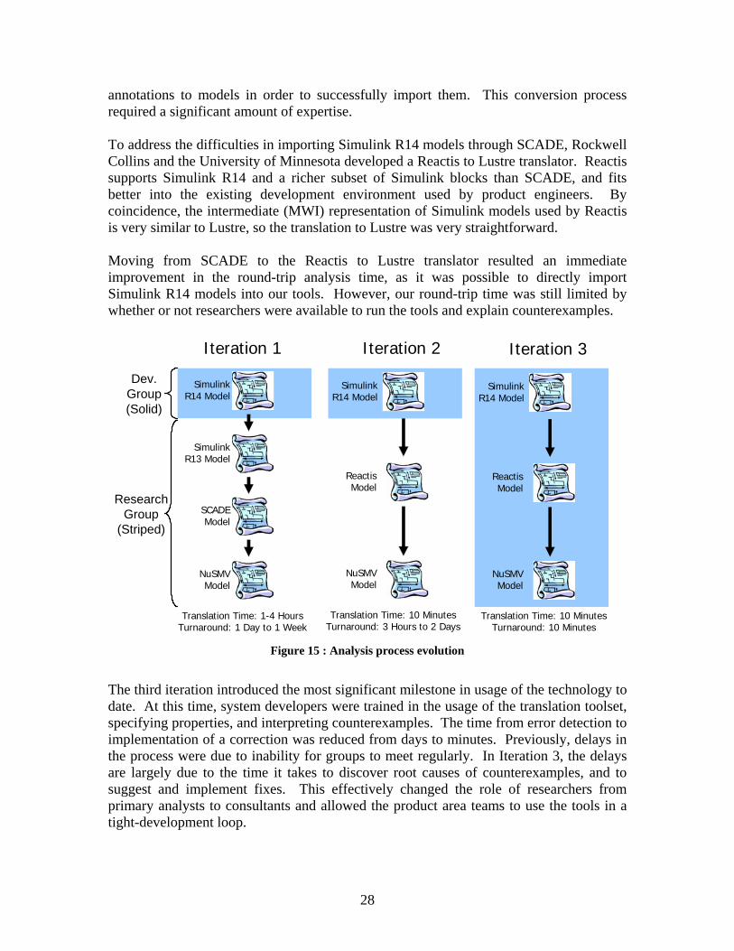
4.3. Analysis Process During the lifetime of the project, the analysis process underwent significant changes from the previous analysis effort described in [24]. In that effort, the translation process was performed by researchers utilizing the Simulink gateway of SCADE to translate into NuSMV. Feedback was provided to the development group by meeting on a semi-weekly basis to discuss problems found. In this project, the process has evolved to where all the analysis is now being done by the project engineers. This evolution is outlined in Figure 15. The first iteration involved using SCADE as an intermediate tool to convert between Simulink and our analysis tools. This conversion process required a significant amount of effort because Simulink Gateway provided in the SCADE toolset did yet not support the direct translation of Simulink R14 models. Instead, we would convert R14 models into R13, which could then be imported into SCADE. Furthermore, SCADE usually required manual
28
annotations to models in order to successfully import them. This conversion process required a significant amount of expertise. To address the difficulties in importing Simulink R14 models through SCADE, Rockwell Collins and the University of Minnesota developed a Reactis to Lustre translator. Reactis supports Simulink R14 and a richer subset of Simulink blocks than SCADE, and fits better into the existing development environment used by product engineers. By coincidence, the intermediate (MWI) representation of Simulink models used by Reactis is very similar to Lustre, so the translation to Lustre was very straightforward. Moving from SCADE to the Reactis to Lustre translator resulted an immediate improvement in the round-trip analysis time, as it was possible to directly import Simulink R14 models into our tools. However, our round-trip time was still limited by whether or not researchers were available to run the tools and explain counterexamples.
Translation Time: 1-4 HoursTurnaround: 1 Day to 1 Week
Iteration 1
Simulink R14 Model
Simulink R13 Model
SCADE Model
NuSMVModel
Translation Time: 10 MinutesTurnaround: 3 Hours to 2 Days
Iteration 2
Simulink R14 Model
ReactisModel
NuSMVModel
Translation Time: 10 MinutesTurnaround: 10 Minutes
Iteration 3
Simulink R14 Model
ReactisModel
NuSMVModel
Research Group
(Striped)
Dev. Group(Solid)
Figure 15 : Analysis process evolution
The third iteration introduced the most significant milestone in usage of the technology to date. At this time, system developers were trained in the usage of the translation toolset, specifying properties, and interpreting counterexamples. The time from error detection to implementation of a correction was reduced from days to minutes. Previously, delays in the process were due to inability for groups to meet regularly. In Iteration 3, the delays are largely due to the time it takes to discover root causes of counterexamples, and to suggest and implement fixes. This effectively changed the role of researchers from primary analysts to consultants and allowed the product area teams to use the tools in a tight-development loop.

29
4.4. Causes of Errors Found Many errors were discovered during analysis. Most of these errors can be attributed to several common causes. A discussion of a few of the more prevalent causes follows. The most common type cause of error is the improper use of the rising edge detector block (shown in Figure 16). The function of this block is to detect when a signal goes from FALSE to TRUE.
Figure 16 : Rising edge detector to detect emergency
Figure 16 illustrates a situation where the improper use of the rising edge block can lead to undesired system states. Suppose the EMERGENCY condition input becomes TRUE. When it becomes TRUE, the CHANGE_STATE output is activated. Now suppose the CHANGE_STATE output is lost or not seen during transmission in the system and subsequently not processed. A situation now exists where the EMERGENCY condition is still TRUE, but the CHANGE_STATE input will not be issued again until the EMERGENCY condition is cleared and re-entered. This could lead to hazardous situations and should be avoided. Another common cause of error is the lack of requirements to address the occurrence of multiple events. Some requirements in the system are stated, “When the MODE_X button is pressed, MODE_X will become active.” This requirement does nothing to address the situations when more than one button is pressed with the MODE_X button. Which mode becomes active when the MODE_X button and others are pressed? These concerns are often not addressed in the written requirements. A third common source of error involves copy/paste reuse errors where a portion of a diagram is copied into another subsystem and modified to fit the requirements of the new subsystem. In this instance, a single error within the original subsystem can be propagated to several locations leading to many property violations and counterexamples. Similarly, violations often occur if the copied diagram does not precisely match the requirements of the new context. Our experience reinforces that this kind of “reuse” must be done with care. The last common cause of error, although trivial, is incorrect connection of inputs from subsystem to subsystem. In large systems, such as the window manager, the connection of inputs can become quite confusing, and errors can be made. Signals must often be routed through several subsystem layers to reach the subsystem where they contribute to the behavior of the model, and each of these layers may be large and complex, so these errors can be difficult to find using only inspections. However, the model-checker can quickly find these errors.

30
5. Conclusions and Directions for Future Work This report described the large-scale use of formal methods to verify the behavior of production avionics software. In this effort, we verified the correctness of the majority of the functional behavior of the ADGS-2100 window manager, analyzing over 16,000 primitive Simulink blocks organized into 4,000 Simulink subsystem instances, against high-level requirements expressed as 563 temporal logic properties. As a result, 98 errors in the high-level requirements and Simulink models were found and corrected. This effort provides a significant example of a successful and cost-efficient application of formal methods to remove defects early in the design cycle. Our success was predicated on understanding the needs and development processes of the systems and software engineers who were building the WM application. We identified several challenges that had to be solved in order to meet these needs:
• Determining how to map software requirements into formal properties
• Creating translators that would allow commercial modeling tools (such as Simulink [10]) to be quickly and automatically analyzed by different formal analysis tools
• Creating tools that allow analysis results (counterexamples) to be easily understood by the analysts and product engineers
• Defining methods for partitioning the application of interest into subsystems that can be analyzed individually
• Creating a verification process to ensure that: 1) the analysis results are sound, 2) all formal properties are traceable to software requirements, and 3) all requirements of interest are verified through one or more formal properties
• Iterating our verification process with the goal of faster turn-around between development and analysis to create a more efficient and higher quality process.
By addressing these challenges, we achieved significant buy-in from the WM developers, and by the end of the project they had assumed responsibility for analyzing the models and ownership of the safety properties. Our approach was an extension of the one detailed in [24]. In this effort we focused on improving the scalability and turnaround time of analysis and the usability of the tools. The most significant step was the introduction of the new translation path from the Reactive Systems tool, Reactis, directly to the Lustre specification language. This contributed considerably to the improvement in time required to correct errors, and cost reduction. In the future, we will focus on extending the current technology to include analysis of systems with real variables and large-domain integers. Although our existing tools have been very effective in analyzing Boolean and enumerated models, we would like the capability to be able better address flight-critical systems in which real- and integer-valued variables play a critical role. We are continuing to add support for a larger
31
number of Simulink blocks, and plan to support StateFlow [23], a sub-language for specifying control logic built into Simulink, in the near future. We also plan to improve several user interface and ease-of-use issues in the current toolset. One of the most cumbersome steps in the current process involves specifying and tweaking the valid ranges for integer variables within models. For integer variables being used as enumerations, the valid ranges of a variable can be derived from the assignment equation for the variable in the the model. This step would significantly reduce the set-up time necessary to prepare a model for analysis. Our eventual goal is to see formal analysis tools used as part of development in the same way as a compiler or simulation tool. At the end of this project, a developer could translate an analysis model through our tool chain and analyze it in a matter of minutes. This quick turnaround allowed developers to integrate model checking into their standard “build a little, test a little” development cycle. Although our current tool suite does not yet match our ease-of-use goals, we are at a point where developers can quickly and easily check large models for critical safety properties, and we are actively working to improve the tool suite and our analysis process.
References [1] S. Bensalem, et. al, An Overview of SAL, in Proceedings of LFM 2000: Fifth NASA
Langley Formal Methods Workshop, Editor: C. Michael Holoway, pg. 187-196, Hampton, VA, June 2000.
[2] G. Berry and G. Gonthier, The Synchronous Programming Language Esterel: Design, Semantics, and Implementation, Science of Computer Programming, Volume 19, pages 87-152, 1992.
[3] A. Benveniste, P. Caspi, S. Edwards, N. Halbwachs, P. Le Guernic, and R.de Simone, The Synchronous Languages 12 Years Later, Proceedings of the IEEE, Volume 91, Issue 1, January 2003.
[4] M. Bozzano, A. Cavallo, M. Cifaldi, L. Valacca, and A. Villafiorita, Improving Safety Assessment of Complex Systems : An Industrial Case Study. Proceedings of Formal Methods 2003 (LNCS 2805), Springer-Verlag, pages 208-222, 2003.
[5] M. Bozzano and A. Villafiorita, Improving System Reliability via Model Checking: the FSAP / NuSMV-SA Safety Analysis Platform, Proceedings of SAFECOMP 2003, pages 49-62, Edinburgh, Scotland, September 23-26, 2003.
[6] R. Butler, S. Miller, J. Potts, and V. Carreno, A Formal Methods Approach to the Analysis of Mode Confusion, Proceedings of the 17th AIAA/IEEE Digital Avionics Systems Conference, Bellevue, WA, October 1998.
[7] J. Chilenski and S. Miller, Applicability of Modified Condition/Decision Coverage to Software Testing, IEE Software Engineering Journal, Volume 9, Number 5, pg. 193-200, September 1994.
[8] Y. Choi, M. P.E. Heimdahl, and S. Rayadurgam, Domain reduction abstraction. Technical Report 02-013. University of Minnesota, April 2002

32
[9] E. Clarke, O. Grumberg, and P. Peled, Model Checking, The MIT Press, Cambridge, Massachusetts, 2001.
[10] J. Dabney and T. Harmon, Mastering Simulink, Pearson Prentice Hall: Upper Saddle River, NJ, 2004.
[11] E. Emerson, Temporal and Modal Logic, Handbook of Theoretical Computer Science, Volume B: Formal Models and Semantics, J. van Leeuwen, ed., North-Holland Pub. Co./MIT Press, Pages 995-1072, 1990.
[12] Esterel Technologies, http://www.esterel-technologies.com. [13] S. Faulk, J. Brackett, P. Ward, and J. Kirby, Jr, The CoRE Method for Real-Time
Requirements, IEEE Software, 9(5):22-33, September 1992. [14] FSAP/NuSMV-SA, http://sra.itc.it/tools/FSAP. [15] D. Harel, Statecharts : A Visual Formalism for Complex Systems, Science of Computer
Programming, 8(3):231-274, June 1987. [16] N. Halbwachs, P. Caspi, P. Raymond, and D. Pilaud, The Synchronous Dataflow
Programming Language LUSTRE, Proceedings of the IEEE, 79(9): 1305-1320, September 1991.
[17] N. Halbwachs and S. Baghdadi, Synchronous Modeling of Asynchronous Systems, Proceedings of EMSOFT'02, LNCS 2491, Springer-Verlag, Grenoble, October 2002.
[18] C. Heitmeyer, R. Jeffords., and B. Labaw, Automated Consistency Checking of Requirements Specification, ACM Transactions on Software Engineering and Methodology (TOSEM), 5(3):231-261, July 1996.
[19] IRST, The NuSMV Model Checker, http://nusmv.irst.itc.it/. [20] A. Joshi, S. P. Miller, and M. P. E. Heimdahl, Mode Confusion Analysis of a Flight
Guidance System Using Formal Methods, Proceedings of the 22nd Digital Avionics Systems Conference (DASC’03), Indianapolis, Indiana, Oct. 12-16, 2003.
[21] N. Leveson, M. Heimdahl, H. Hildreth, and J. Reese, Requirements Specifications for Process-Control Systems, IEEE Transactions on Software Engineering, 20(9):684-707, September 1994.
[22] The Mathworks, http://www.mathworks.com. [23] The Mathworks, Stateflow Home Page, http://www.mathworks.com/products/stateflow/ [24] S. Miller, Elise A. Anderson, Mats P.E. Heimdahl, and Michael W. Whalen, FGS
Autocoding Interim Report, NASA Contractor Report, February 2005 [25] S. Miller, M. P.E. Heimdahl, and A.C. Tribble, Proving the Shalls, Proceedings of FM 2003:
the 12th International FME Symposium, Pisa, Italy, Sept. 8-14, 2003. [26] S. Miller, A. Tribble, T. Carlson and E. J. Danielson, Flight Guidance System Requirements
Specification, NASA/CR-2003-212426, June 2003. [27] S. Miller, M. Whalen, D. O’Brien, M. Heimdahl, and A. Joshi, FGS Partitioning Final
Report, NASA Contractor Report, November 2004. [28] S. Owre, J. Rushby, N. Shankar, and F. Henke, Formal Verification for Fault-Tolerant
Architectures: Prolegomena to the Design of PVS, IEEE Transactions on Software Engineering, Vol. 21, No. 2, pg. 107-125, February 1995.
[29] Reactive Systems, Inc, Reactis Home Page, http://www.reactive-systems.com. [30] N. Scaife, C. Sofronis, P. Caspi, S. Tripakis, and F. Maraninchi, Defining and translating a
"safe" subset of Simulink/Stateflow into Lustre. 4th ACM International Conference on Embedded Software (EMSOFT'04), Pisa, Italy, September 2004
[31] SRI, PVS Home Page, http://www.csl.sri.com/projects/pvs/.

33
[32] SRI, SAL Home Page, http://www.csl.sri.com/projects/sal/. [33] J. Thompson, M. Heimdahl, and S. Miller.: Specification Based Prototyping for Embedded
Systems, Proceedings of the Seventh ACM SIGSOFT Symposium on the Foundations on Software Engineering, LNCS 1687, September 1999.
[34] A. C. Tribble, David D. Lempia, and Steven P. Miller, Software Safety Analysis of a Flight Guidance System, Proceedings of the 21st Digital Avionics Systems Conference (DASC'02), Irvine, California, Oct. 27-31, 2002.
[35] A. C. Tribble, Steven P. Miller and David L. Lempia, Software Safety Analysis of a Flight Guidance System , NASA/CR-2004-213004, March 2004.
[36] M. Whalen, A formal semantics for RSML-e. Master's thesis, University of Minnesota, May 2000