additive manufacturing of ultem polymers and composites · engine components by fused depostion...
TRANSCRIPT
Additive Manufacturing of Ultem Polymers and Composites
Kathy C. Chuang, Joseph E. Grady and Robert D. Draper
NASA Glenn Research Center, Cleveland, OH
Euy-Sik E. Shin
Ohio Aerospace Institute, Cleveland, OH
Clark Patterson and Thomas D. Santelle
Rapid Prototype Plus Manufacturing (rp+m), Avon Lake, OH
https://ntrs.nasa.gov/search.jsp?R=20160000203 2020-05-19T14:57:03+00:00Z

Fused Deposition Modeling (FDM): a polymer filament is melted and then
deposited in successive layers to build a 3D component according to a
computer-aided design (CAD) file
a) Acoustic liner & components b) Perforated engine access door Ultem 9085 Ultem 9085
Modulate Sound Wave Reduce Noise
♦ Wind tunnel tests showed that FDM-printed acoustic liners performed
as good as conventional liners (Honeycombs/facesheets)
♦ Unconventional acoustic liners by AM can modulate multiple frequencies
Advantages of Additive Manufacturing
● Quick turn around time for complex parts
● Shorten production and testing cycle
● Save money for low production volume parts

Fused Deposition Modeling Simplifies
Acoustic Liner Fabrication
Perforated Facesheet Bonded Structure Honeycomb
Fabricated with monolithic Ultem 9085 thermoplastic (Tg = 367⁰F)
Current manufacturing approach requires honeycomb, bonding and drilling
Integral facesheet/honeycomb
structure is fabricated in one step
using Fused Deposition Modeling
standard liner
configurationcomplex
geometries
200ºF Operating Temperature

Fused Deposition Modeling Enables Fabrication
of Advanced Acoustic Liner Concepts
Acoustically-tuned passages provide broadband noise attenuation
Fabricated 16x2 inch test article
FDM sampleof advanced
liner
LaRC acoustic measurements suggestthat optimized concept could outperform current liner designs

Structural Integrity of Inlet Guide Vane was evaluated under aerodynamic loading
Vane Configuration in Cascade Rig
NASA Glenn Cascade Rig
Other FDM composites being evaluated:
Matrix (+C fiber) Use Temperature (⁰F)
Ultem 1000 350
Ultem 9085 275
ABS 200Deformation MeasurementsStress Analysis

Mechanical Properties of UltemsFDM Printing vs Injection Molding
Resin Type
Properties
Ultem 9085
Injection
Molded
(Sabic
data)
Ultem 9085
FDM
(Stratasys
data)
0°
Ultem 9085
FDM rp+m
(GRC
tested)
±45°
Ultem
1000
Injection
Molded
(Sabic
data)
Ultem 1000 +
10wt% AS4
FDM rp+m
(GRC tested)
0° / ±45°
Tensile
Strength (MPa)83 72 62 110 50 / 44
Tensile
Modulus (MPa)3,432 2,200 2,090 3,579 2,860 / 2,092
Flexural
Strength (MPa)137 115 92 165 tbd
Flexural
Modulus (MPa) 2,913 2,500 1,901 3,511 tbd
Compression
Strength
(MPa)
n/a 104 tbd n/a tbd
Compression
Modulus (MPa)n/a 1,930 1,890 n/a tbd
Typical RT mechanical properties
♦ Ultem 9085 FDM prints contains about 5-8% voids.
♦ FDM-properties are inferior to Injection molding
due to higher porosity:
● More Brittle
● lower elongation
♦ FDM properties depend on:
● built direction & raster angle
● thickness of the filaments
● tool path generation
● air gap between raster in the filled pattern
Tensile properties of Ultem 9085 & C-filled Ultem 1000 as-received

Engine Components by Fused Depostion Modeling
♦ Quality evaluation of the first trial composite vanes made of Ultem 1000 + 10wt% C-fiber
♦ 23-26% porosity (acid digestion) in Ultem 1000 composite vanes
♦ 33% porosity determined by optical microscope images
Balance Acid digestion
Mc, g Vc, cc rc, g/cc Mf, g Mm, g Vf, cc Vm, cc Vp, cc
Ha1 0.7731 0.831 0.931 0.0712 0.702 0.0398 0.5527 0.2385 9% 5% 28.7%
Ha2 0.3977 0.374 1.063 0.0498 0.348 0.0278 0.2739 0.0722 13% 7% 19.3%
Ha3 0.9433 0.952 0.992 0.0894 0.854 0.0499 0.6724 0.2297 9% 5% 24.1%
Ha4 0.6676 0.734 0.911 0.0753 0.592 0.0421 0.4664 0.2256 11% 6% 30.7%
Ha5 1.1184 1.194 0.939 0.0627 1.056 0.0350 0.8313 0.3277 6% 3% 27.4%
Avg 10% 5% 26%
S.D. 3% 2% 4%
Va1 0.8706 0.929 0.938 n/a
Va2 0.3349 0.347 0.966 0.0346 0.300 0.0193 0.2365 0.0912 10% 6% 26.3%
Va3 0.5443 0.492 1.112 0.0413 0.503 0.0231 0.3961 0.0729 8% 5% 14.8%
Va4 0.637 0.695 0.92 0.0632 0.574 0.0353 0.4518 0.2079 10% 5% 29.9%
Va5 1.2997 1.25 1.037 0.0833 1.216 0.0465 0.9578 0.2457 6% 4% 19.7%
Avg 9% 5% 23%
S.D. 2% 1% 7%
From Theor. Density FWF
wt%
FVF
v%
porosity
v%Pycnometer
After dryingSample
ID
♦ Fiber weight fraction, 10wt%, from the acid digestion consisted with the formulation
♦ No significant difference between the horizontal and vertical vanes in FVF and porosity
Optical Image of Horizontal Vanes
Optical Image of Vertical Vanes

XChopped fibers aligned along the filament axis
as expected from extrusion
Y cross-section #1
Z cross-section #2
after removing ~ 1mm Z cross-section #3 after removing ~ 2mm
Evaluation of As-received Fiber Filaments (Thick)
and FDM-extruded Filaments at 420 ºC (Thin)
Balance
Mc, g Vc, cc rc, g/cc Mf, g Mm, g Vf, cc Vm, cc Vp, cc
Filament, thick 0.2753 0.2084 1.3209 0.0254 0.250 0.014 0.1968 -0.003 9% 7% -1.2%
Filament, thin 1 0.0582 0.0645 0.9029 0.0054 0.053 0.003 0.0416 0.02 9% 5% 30.9%
thin 2 0.0583 0.0653 0.8924 0.0054 0.053 0.003 0.0417 0.021 9% 5% 31.6%
FWF,
wt%
FVF,
v%
porosity,
v%
After drying
Sample ID Pycnometer Acid digestionFrom Theor. Density
As-ReceivedUltem 1000
(Thick)
0% Porosity15% Porosity
Ultem 1000 thin filament extruded at 420°C exhibited ~30% porosityFDM-extruded
at 420°C
(Thin)

Void formation mechanisms of the currently printed Ultem 1000 + 10wt% C-fiber composite?
− Evaluated the filament feedstock: As-received (Thick) vs. exposed to 420 °C thru printer inlet (Thin)
TGA curves show changes in material behavior from pellet, to extruded filament, and to 420 °C
exposed filament, i.e., thermal degradation onset temperature decreased gradually and
weight loss pattern changed

Void formation mechanisms of the currently printed Ultem 1000 + 10wt% AS4 C-fiber composite?
− Evaluated the filament feedstock: As-received (Thick) vs. exposed to 420 °C thru printer inlet (thin)
♦ TGA-FTIR confirmed that the initial weight loss up to 300 °C was due to vaporization of the trapped water
or other volatiles generated at 420 °C inside the extruded filaments
♦ Drying of the filament prior to printing recommended: 100 °C for a couple of hours 200 °C for 6-14 hrs
to prevent any potential softening blistering of filaments ♦ Ultimate remedy ⇒ dry filaments after compounding and keep them dry during filament extrusion process
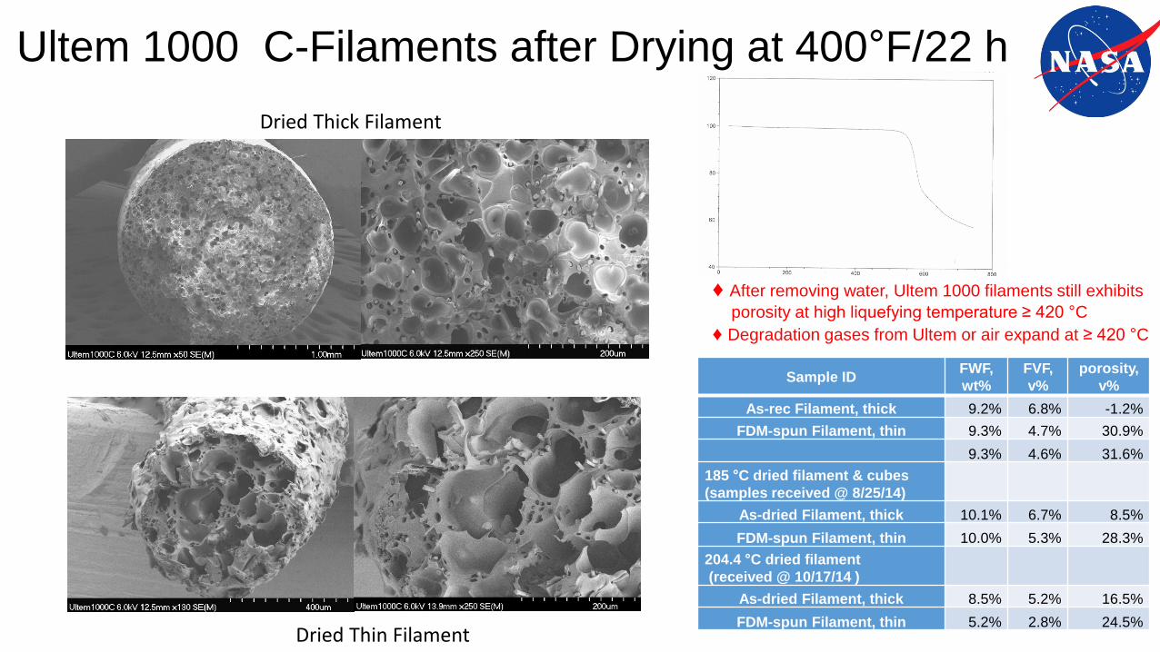
Ultem 1000 C-Filaments after Drying at 400°F/22 h
Dried Thick Filament
Dried Thin Filament
Sample IDFWF,
wt%
FVF,
v%
porosity,
v%
As-rec Filament, thick 9.2% 6.8% -1.2%
FDM-spun Filament, thin 9.3% 4.7% 30.9%
9.3% 4.6% 31.6%
185 °C dried filament & cubes
(samples received @ 8/25/14)
As-dried Filament, thick 10.1% 6.7% 8.5%
FDM-spun Filament, thin 10.0% 5.3% 28.3%
204.4 °C dried filament
(received @ 10/17/14 )
As-dried Filament, thick 8.5% 5.2% 16.5%
FDM-spun Filament, thin 5.2% 2.8% 24.5%
♦ After removing water, Ultem 1000 filaments still exhibits
porosity at high liquefying temperature ≥ 420 °C
♦ Degradation gases from Ultem or air expand at ≥ 420 °C

Tensile Strength of Ultem 9085, XH6050 and AS4-filled Ultem 1000Printed by FDM
♦ Dried Ultem 1000 filled with 10% chopped AS4 showed 40% higher modulus than Ultem 9085.
♦ Ultem 9085 exhibited highest elongation.♦ XH6050 (Tg= 245°C) displayed inferior strength than Ultem 9085 (Tg= 186°C), despite higher Tg.
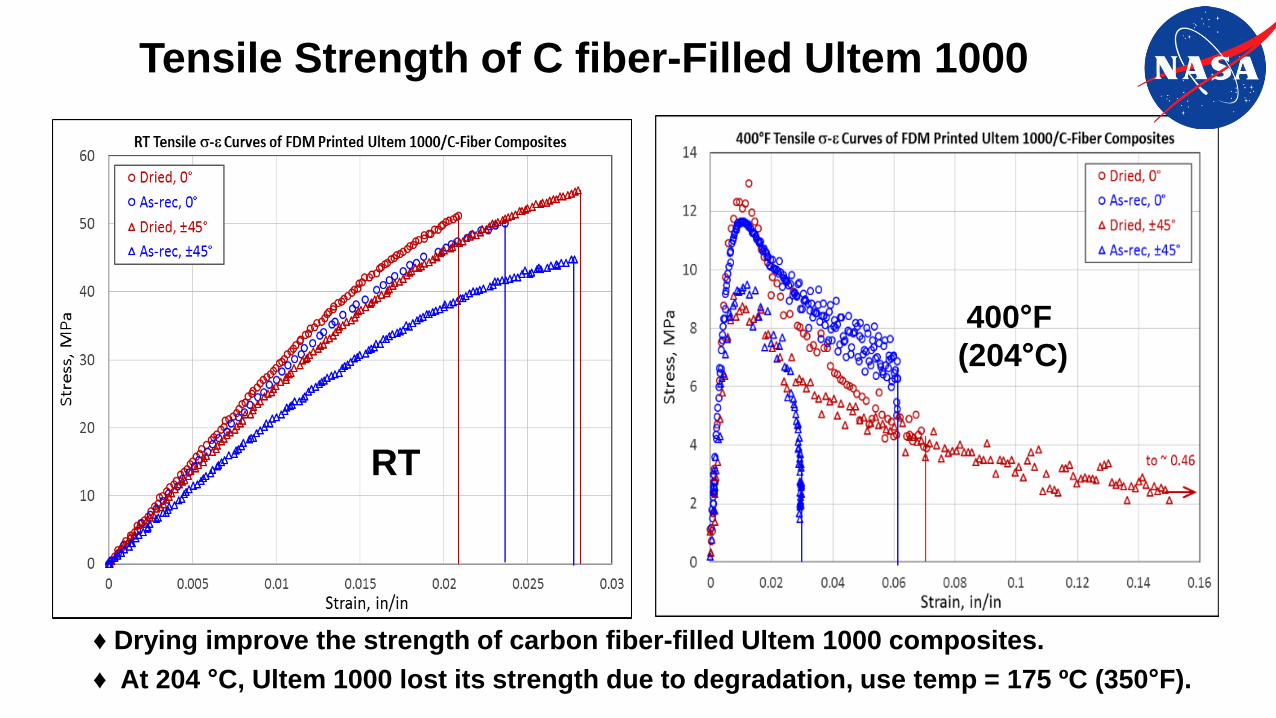
Tensile Strength of C fiber-Filled Ultem 1000
RT
400°F
(204°C)
♦ Drying improve the strength of carbon fiber-filled Ultem 1000 composites.
♦ At 204 °C, Ultem 1000 lost its strength due to degradation, use temp = 175 ºC (350°F).

14
Ultem 9085As-Received
0.3-0.4% moisture
Fiber-filled Ultem 1000As-received
0.6% water moisture
Ultem9085 FDM-extruded@375°C
Fiber-filled Ultem 1000FDM-extruded@420°C
Approaches to Reduce Porosity in Fiber-Filled Ultem 1000 for FDM
♦ Ultem 1000 viscosity is 3-fold higher than that of Ultem 9085
♦ Porosity in FDM printing of Ultem 1000 at 420°C caused by
volume expansion of moisture, trapped air & degradation gases
♦ Solution: Produce Ultem 1000 with controlled molecular weight
with similar viscosity as Ultem 9085 to enable printing
Ultem 1000 at 380°C
Complex Viscosity of Ultem 9085 and Ultem 1000

Summary and Conclusion
♦ FDM-printed Ultem 9085 acoustic liner components exhibited similar performance in
a wind tunnel as the conventional liners made of honeycombs and facesheets.
♦ Unconventional liners printed by FDM potentially could modulate multiple frequencies
instead of just a single frequency in conventional liners.
♦ Composite vanes were printed by FDM at 420°C with 25% porosity and tested in a
cascade rig, using Ultem 1000 filled with 10% carbon fiber.
♦ The porosity of FDM printed ultem 1000 with fibers were caused by volume expansion of
absorbed moisture (0.6%), trapped air during extrusion and degradation gases generated
at high liquefying temperature at 420°C.
♦ Fiber-filled Ultem 1000 filaments become more brittle, but drying improved the tensile strength.
♦ Need to produce Ultem 1000 with controlled molecular weight to lower its viscosity comparable
to Ultem 9085 in order to allow printing at 380°C to reduce the porosity of Ultem 1000 by FDM.
♦ FDM properties depends on built direction, raster angle, filament thickness,
tool path generation and air gap between rasters
♦ FDM printed specimens exhibited lower mechanical properties than injection molded parts
due to inherent porosity associated with FDM

Acknowlegements
Pete Bonacuse,GRC-LMA, Joy Buehler/LMA-VPL, Chris Burke/LM-SLI,
Chris Kantzos/GRC, LERCIP intern, Rich Martin/LMA-CSU,
Linda McCorkle & Daniel Scheiman /LMN-OAI, D. Jordan McCrone/ LMA-VPL,
Bob Pelaez/GRC-FTH, Larry Smith/FTC-Jacobs, Tim Ubienski/FTH-SLI,
Nathan Wilmoth/LMA-VPL, rp+m staffs.
Chao Lao, Morgan Rhein & Jeremy Mehl/2014 NASA Academy Students
♦ Funding for 2014 NASA Aeronautic Seedling Fund — Non-Metallic Engines
♦ Contribution for characterization and testing and FDM printing: