additive manufacturing for guided bone regeneration: a
TRANSCRIPT

International Journal of
Molecular Sciences
Review
Additive Manufacturing for Guided BoneRegeneration: A Perspective for AlveolarRidge Augmentation
Patrick Rider 1,* , Željka Peric Kacarevic 2, Said Alkildani 3 , Sujith Retnasingh 4,Reinhard Schnettler 5 and Mike Barbeck 5
1 Botiss Biomaterials GmbH, Hauptstr. 28, 15806 Zossen, Germany2 Department of Anatomy, Histology and Embryology, Faculty of Dental Medicine and Health,
Josip Juraj Strossmayer University of Osijek, Osijek 31000, Croatia; [email protected] Department of Biomedical Engineering, Faculty of Applied Medical Sciences, German-Jordanian University,
Amman 11180, Jordan; [email protected] Institutes for Environmental Toxicology, Martin-Luther-Universität, Halle-Wittenberg and Faculty of
Biomedical Engineering, Anhalt University of Applied Science, 06366 Köthen, Germany;[email protected]
5 Department of Oral and Maxillofacial Surgery, University Hospital Hamburg-Eppendorf, 20246 Hamburg,Germany; [email protected] (R.S.); [email protected] (M.B.)
* Correspondence: [email protected]; Tel.: +49-30-2060739858
Received: 27 September 2018; Accepted: 21 October 2018; Published: 24 October 2018�����������������
Abstract: Three-dimensional (3D) printing has become an important tool in the field of tissueengineering and its further development will lead to completely new clinical possibilities.The ability to create tissue scaffolds with controllable characteristics, such as internal architecture,porosity, and interconnectivity make it highly desirable in comparison to conventional techniques,which lack a defined structure and repeatability between scaffolds. Furthermore, 3D printing allowsfor the production of scaffolds with patient-specific dimensions using computer-aided design.The availability of commercially available 3D printed permanent implants is on the rise; however,there are yet to be any commercially available biodegradable/bioresorbable devices. This review willcompare the main 3D printing techniques of: stereolithography; selective laser sintering; powderbed inkjet printing and extrusion printing; for the fabrication of biodegradable/bioresorbable bonetissue scaffolds; and, discuss their potential for dental applications, specifically augmentation of thealveolar ridge.
Keywords: bone scaffold; additive manufacturing; 3D printing; bone regeneration; dentistry;bone augmentation
1. Introduction
Additive manufacture (AM) has been shown as a promising fabrication technique for theproduction of bone replacement scaffolds. Customization and repeatability of designs, as well asthe precise control over scaffold architecture, make AM superior to conventional techniques.The availability of additively manufactured permanent implantable medical devices is beginningto increase [1], however, there are yet to be commercially produced additively manufacturedbiodegradable/bioresorbable scaffolds.
This review will report on the research that was conducted into the AM of biodegradable/bioresorbable bone implants, broken down into the materials used. The end of the review will then be
Int. J. Mol. Sci. 2018, 19, 3308; doi:10.3390/ijms19113308 www.mdpi.com/journal/ijms

Int. J. Mol. Sci. 2018, 19, 3308 2 of 35
used to assess the suitability of each technique, based on the conducted research, for the application ofalveolar ridge augmentation.
1.1. Alveolar Ridge Augmentation
Augmentation of the alveolar ridge is an important procedure for enabling the placement of dentalimplants, and thus, to restore both functionality and esthetic appearance. Successful implant placementis reliant upon adequate alveolar bone volume at the implant site to provide mechanical stability andanchor the implant in position. Augmentation can be achieved through the application of differentbone augmentation materials. In this context, granular bone or bone blocks are applied to achievebone augmentation via guided bone regeneration (GBR). The bone graft acts to provide mechanicalsupport, space provision, blood clot stabilization, and bony ingrowth; these are the important factorsthat must be replicated in any AM design.
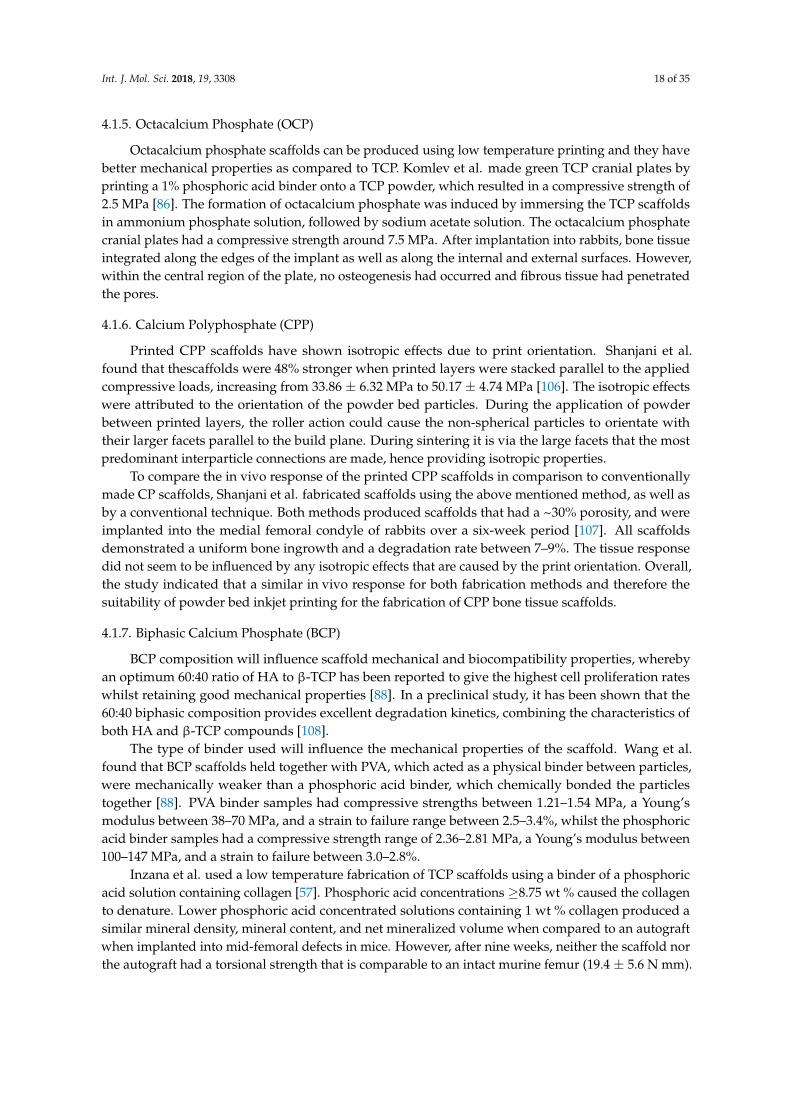
Bone grafting materials can be divided into autologous, allogenic, xenogeneic and alloplastic.Autografts, allografts and xenografts tend to be brittle due to their post-extraction processing, howeverdemonstrate excellent tissue ingrowth [2,3], as demonstrated in Figure 1. Alloplastic scaffolds that arecreated through conventional manufacturing techniques tend to have poorly defined structures, dueto a limited control of material placement during scaffold fabrication [4]. A common disadvantagefor the currently used bone substitute materials is the variability and lack of reproducibility betweenindividual bone grafts.
Int. J. Mol. Sci. 2018, 18, x FOR PEER REVIEW 2 of 35
review will then be used to assess the suitability of each technique, based on the conducted research,
for the application of alveolar ridge augmentation.
1.1. Alveolar Ridge Augmentation
Augmentation of the alveolar ridge is an important procedure for enabling the placement of
dental implants, and thus, to restore both functionality and esthetic appearance. Successful implant
placement is reliant upon adequate alveolar bone volume at the implant site to provide mechanical
stability and anchor the implant in position. Augmentation can be achieved through the application
of different bone augmentation materials. In this context, granular bone or bone blocks are applied
to achieve bone augmentation via guided bone regeneration (GBR). The bone graft acts to provide
mechanical support, space provision, blood clot stabilization, and bony ingrowth; these are the
important factors that must be replicated in any AM design.
Bone grafting materials can be divided into autologous, allogenic, xenogeneic and alloplastic.
Autografts, allografts and xenografts tend to be brittle due to their post-extraction processing,
however demonstrate excellent tissue ingrowth [2,3], as demonstrated in Figure 1. Alloplastic
scaffolds that are created through conventional manufacturing techniques tend to have poorly
defined structures, due to a limited control of material placement during scaffold fabrication [4]. A
common disadvantage for the currently used bone substitute materials is the variability and lack of
reproducibility between individual bone grafts.
Figure 1. Xenogeneic bone graft (Cerabone®) showing seamless tissue integration. Arrows are used
to highlight the bone graft/host bone tissue interface.
1.2. Optimal Properties of Bone Tissue Scaffolds
Autografts are the gold standard in the regeneration of bone tissue, however due to donor’s site
morbidity, low quality of geriatric/pathological sources, or the need for two invasive surgeries,
alternative bone grafting scaffolds are needed. An idealized scaffold should be replaced by the host
bone tissue, through osteoinductive and osteoconductive material properties [5,6]. The main types of
degradable bone graft materials are natural polymers, synthetic polymers and bioceramics.
An idealized bone tissue scaffold for alveolar bone augmentations must fulfill a specific criteria:
be biocompatible, match the physical properties of the bone tissue to be replaced, not to elicit a
chronic immune response and to fully integrate with the bone [5,7]. The manufacturing process, as
well as design parameters, such as porosity, pore size, scaffold interconnectivity, and mechanical
strength, have been shown to influence the osteogenic cell interaction [8–10].
Figure 1. Xenogeneic bone graft (Cerabone®) showing seamless tissue integration. Arrows are used tohighlight the bone graft/host bone tissue interface.
1.2. Optimal Properties of Bone Tissue Scaffolds
Autografts are the gold standard in the regeneration of bone tissue, however due to donor’ssite morbidity, low quality of geriatric/pathological sources, or the need for two invasive surgeries,alternative bone grafting scaffolds are needed. An idealized scaffold should be replaced by the hostbone tissue, through osteoinductive and osteoconductive material properties [5,6]. The main types ofdegradable bone graft materials are natural polymers, synthetic polymers and bioceramics.
An idealized bone tissue scaffold for alveolar bone augmentations must fulfill a specific criteria:be biocompatible, match the physical properties of the bone tissue to be replaced, not to elicit a chronicimmune response and to fully integrate with the bone [5,7]. The manufacturing process, as well as

Int. J. Mol. Sci. 2018, 19, 3308 3 of 35
design parameters, such as porosity, pore size, scaffold interconnectivity, and mechanical strength,have been shown to influence the osteogenic cell interaction [8–10].
The mechanical properties of the scaffolds should be equivalent to that of the hostbone. Alveolar bone has a cortical thickness between 2.1–2.4 mm and a density between1.64–1.75 mg/cm3 [11]. Bone tissue scaffolds are usually compared to the compressive strengths ofcancellous bone, which in the human mandible, ranges between 0.22 to 10.44 MPa with a mean valueof 3.9 ± 2.7 MPa [12], however this can change depending on bone density, age, and gender [13,14].Finite element analysis of dental implants during mastication has shown that, when experiencing anapplied bite force of 146 N, a compressive stress of 62 MPa is produced on the surrounding alveolarbone that supports the dental implant [15]. Compressive forces on the alveolar bone increased to122 MPa when the angular abutment of the implant was changed from 0◦ to 20◦. This demonstratesthe range of forces that the bone graft could be subjected to, and therefore, the necessity of the bonegraft to fully integrate and be replaced by the host bone tissue, thereby increasing its mechanicalstrength to withstand such forces. Usually, after the placement of a bone graft and the insertion ofa dental implant, there is a healing period to allow for tissue integration before the implant and thesurrounding supporting structures must sustain mechanical loading.
Porosity, including pore size and interconnectivity, enable tissue penetration, surface area forbiological fixation, and bony integration. Optimal osteoconductivity has been achieved with pore sizessimilar to the native structure of cancellous bone [16–18], which has pore sizes ranging between200–500 µm and a 30–90% porosity [19]. Even though small pore sizes in vitro induce earlierosteogenesis by limiting cell proliferation, larger pore sizes in vivo improve bone structure and tissuepenetration [16].
The ideal scaffold should be biodegradable/bioresorbable. Biodegradation and bioresorptionare used to indicate the breakdown of a material when introduced into a living organism; however,these two terms have different meanings [20]. Biodegradation refers to the chemical breakdownmediated by agents, like cells, enzymes, or microorganisms. For example, natural polymers, such ascollagen, which are broken down by collagenase enzymes, cleaving the molecular chain via itspeptide bonds [21]. On the other hand, bioresorption implies that the implant and its by-productsare removed by cellular activities, such as phagocytosis. An example of bioresorption would beosteoclasts remodeling implanted hydroxyapatite in vivo, where hydroxyapatite gets surrounded by abony matrix and is slowly resorbed into the structure [22]. To produce a bone tissue scaffold with allthe aforementioned characteristics, a variety of biodegradable/bioresorbable materials have been usedalong with different manufacturing techniques. Additive manufacturing offers the greatest possibilitiesfor advancing the development of bone tissue scaffolds by providing control over scaffold designand properties, not attainable through current conventional methods [23]. Scaffolds can be designedon a computer and sent for manufacture, enabling the creation of complex, tailorable, and highlyreproducible scaffolds. The process for using additively manufactured bone tissue scaffolds for repairof the alveolar ridge is depicted in Figure 2. As the materials being discussed in this review havean established biocompatibility and are biodegradable/bioresorbable, this review will focus on theother necessary properties that are required for successful bone augmentation achieved through therespective manufacturing technique.

Int. J. Mol. Sci. 2018, 19, 3308 4 of 35Int. J. Mol. Sci. 2018, 18, x FOR PEER REVIEW 4 of 35
Figure 2. Alveolar ridge augmentation using an additively manufactured bone tissue scaffold. (1) a
bone defect has formed in the alveolar ridge; (2) a bone scaffold is designed and then printed using
additive manufacturing technology; (3) the printed bone scaffold is placed in the defect space to
support bone regeneration; (4) new bone infiltrates the scaffold, eventually degrading or resorbing
the structure; and, (5) a dental implant in positioned in the regenerated bone.
1.3. Additive Manufacturing Techniques (AM)
Three-dimensional (3D) printing, also known as additive manufacture, was developed in the
1980s and has since been applied to bone tissue engineering. In the present review, different additive
manufacturing techniques are discussed. To control the precise porous architecture of a scaffold,
various AM techniques have been developed. Advances in computer-aided design have brought
rapid progress to fabricate custom-made scaffolds directly from computer data. In AM, scaffold
architecture is manufactured by the processing of liquid or powder materials according to
Figure 2. Alveolar ridge augmentation using an additively manufactured bone tissue scaffold.(1) a bone defect has formed in the alveolar ridge; (2) a bone scaffold is designed and then printedusing additive manufacturing technology; (3) the printed bone scaffold is placed in the defect space tosupport bone regeneration; (4) new bone infiltrates the scaffold, eventually degrading or resorbing thestructure; and, (5) a dental implant in positioned in the regenerated bone.
1.3. Additive Manufacturing Techniques (AM)
Three-dimensional (3D) printing, also known as additive manufacture, was developed in the1980s and has since been applied to bone tissue engineering. In the present review, different additivemanufacturing techniques are discussed. To control the precise porous architecture of a scaffold,various AM techniques have been developed. Advances in computer-aided design have brought rapid

Int. J. Mol. Sci. 2018, 19, 3308 5 of 35
progress to fabricate custom-made scaffolds directly from computer data. In AM, scaffold architectureis manufactured by the processing of liquid or powder materials according to computerized designs.AM techniques have significant advantages over conventional fabrication techniques, as they canproduce complex scaffolds with a precise external shape, internal morphology, and reproducible 3Darchitecture [24]. Among the different AM techniques, laser-based printing, such as stereolithography(SLA) and selective laser sintering (SLS), extrusion-based printing and inkjet printing are the mostwidely used 3D printing methods used for the fabrication of tissue scaffolds. Research conductedby each manufacturing technique for the production on bone tissue scaffolds will be discussed andsub-divided by the main biodegradable/bioresorbable material used.
2. Stereolithography
Stereolithography (SLA) uses an ultraviolet laser to cure liquid resin into a hardened material ina layer-by-layer fashion. It consists of a reservoir that contains a photosensitive polymer resin anda moveable build platform. This technique works by focusing a UV laser on to the photopolymerresin [25], as demonstrated in Figure 3. Printing often requires the use of photoinitiators to helpwith the curing process, however these can have toxic effects on the cells if any residue remains inthe parts [26]. SLA has one of the highest resolutions; 5–300 µm [26], accuracies and the smoothestsurface finish of all plastic 3D printing technologies, but the main benefit of SLA lies in its versatility.SLA is a great option for highly detailed scaffolds, requiring tight tolerances and smooth surfaces,such as molds, patterns, and functional parts, as it can achieve a spatial resolution of approximately50 µm [25]. Various techniques that fall under SLA, include: two-photon polymerization (2PP) [25],holography [27], and visible light-based [28] techniques. The various SLA techniques offer differentpossibilities, such as improved resolutions of up to 200 nm with 2PP or the use of visible light to avoidthe negative impact of UV light on cells. A wide range of materials can be prepared for SLA (comparedin Table 1), however they are limited by their ability to be processed into a photo-crosslinkable hydrogel,modified by the addition of photo-crosslinkable groups along the molecular chain [29–31].
Int. J. Mol. Sci. 2018, 18, x FOR PEER REVIEW 5 of 35
computerized designs. AM techniques have significant advantages over conventional fabrication
techniques, as they can produce complex scaffolds with a precise external shape, internal
morphology, and reproducible 3D architecture [24]. Among the different AM techniques, laser-based
printing, such as stereolithography (SLA) and selective laser sintering (SLS), extrusion-based printing
and inkjet printing are the most widely used 3D printing methods used for the fabrication of tissue
scaffolds. Research conducted by each manufacturing technique for the production on bone tissue
scaffolds will be discussed and sub-divided by the main biodegradable/bioresorbable material used.
2. Stereolithography
Stereolithography (SLA) uses an ultraviolet laser to cure liquid resin into a hardened material in
a layer-by-layer fashion. It consists of a reservoir that contains a photosensitive polymer resin and a
moveable build platform. This technique works by focusing a UV laser on to the photopolymer resin
[25], as demonstrated in Figure 3. Printing often requires the use of photoinitiators to help with the
curing process, however these can have toxic effects on the cells if any residue remains in the parts
[26]. SLA has one of the highest resolutions; 5–300 μm [26], accuracies and the smoothest surface
finish of all plastic 3D printing technologies, but the main benefit of SLA lies in its versatility. SLA is
a great option for highly detailed scaffolds, requiring tight tolerances and smooth surfaces, such as
molds, patterns, and functional parts, as it can achieve a spatial resolution of approximately 50 μm
[25]. Various techniques that fall under SLA, include: two-photon polymerization (2PP) [25],
holography [27], and visible light-based [28] techniques. The various SLA techniques offer different
possibilities, such as improved resolutions of up to 200 nm with 2PP or the use of visible light to
avoid the negative impact of UV light on cells. A wide range of materials can be prepared for SLA
(compared in Table 1), however they are limited by their ability to be processed into a photo-
crosslinkable hydrogel, modified by the addition of photo-crosslinkable groups along the molecular
chain [29–31].
Figure 3. Schematic of stereolithography (SLA) printing process. The laser source cures the top of the
liquid resin in a predetermined pattern. The platform is then lowered by the height of the cured resin
and the process is repeated.
Figure 3. Schematic of stereolithography (SLA) printing process. The laser source cures the top of theliquid resin in a predetermined pattern. The platform is then lowered by the height of the cured resinand the process is repeated.

Int. J. Mol. Sci. 2018, 19, 3308 6 of 35
Table 1. Summary of SLA Scaffold Properties.
Material Scaffold Mechanical Properties Porosity (%) Cell Viability References
GelMA (Irgacure 2959) 30 kPa * at the highest degree ofmethacrylation Non-porous Highest cell viability was reported in the lowest
concentration of GelMA, 80–95% [29]
SilMA (LAP) 910 kPa ** at the highest percentageof Sil-MA / SilMA exhibited similar absorbance in a cck-8
assay as GelMA [32]
GelMA:SF (Irgacure 2959) Reached 75 kPa ** with the highestconcentration of SF 41.8 Highest OD values was over 2.0, a little bit higher
than the metabolic activity of pure GelMA [30]
Chitosan:PEGDA (Irgacure 819) ~1000 kPa * at the highest concentrationof PEGDA Non-porous
Ratios of 1:5 and 1:10 of Chitosan:PEGDAexhibited the highest cell viabilitypercentages 93–97%
[33]
Methacry. PCL/BG (Lucirin TPO-L) 3.4 MPa/dry *2.5 MPa/wet * 63 Highest metabolic activity at highest
BG concentration [34]
CP CP/PCL 2.04 ± 0.12 MPa **4.55 ± 0.21 MPa ** / CP:PCL had lower proliferation than pure CP but
exhibited higher osteogenic markers expression [35]
Methacrylated Alginate (VA-086) 3.3–12.4 kPa **depending on the photoinitiator content Non-porous 75% at moderate stiffness [36]
Methacrylated PCL (Irgacure 2959, 369) 2.02 ± 2.87 MPa ** 70.5 ± 0.8 Similar metabolic activity as in tissueculture polystyrene [37]
PETMP:PEG-DVE 6.9 ± 1.8 MPa * Non-porous 95% viability was exhibited in 120 h [38]
Methacrylated PLA (camphorquinone)9.43 ± 3.2 MPa with intermediate contentof HA and highest content of TEGDMA(flexural strength)
/ Samples with highest TEGDMA and HA contentexhibited better cell viability. [39]
PTMC/HA (Lucirin TPO-L) / 70 Addition of HA and TEGDMA promoted bettercell attachment and proliferation [40]
* Modulus, ** Strength. Abbreviations: β-TCP: β-tricalcium phosphate, BG: bioglass, GelMA: gelatin methacrylate, HA: hydroxyapatite, PEGDA: polyethylene glycol diacrylate, PEG-DVE:poly(ethylene glycol) divinyl ether, PETMP: pentaerythritol tetrakis(3-mercaptopropionate), PCL: polycaprolactone, PPF: polypropylene fumarate, SilMA: silk methacrylate, SF: silk fibroin,TEGDMA: triethylene glycol dimethacrylate.

Int. J. Mol. Sci. 2018, 19, 3308 7 of 35
2.1. Natural Polymers
2.1.1. Gelatin
Gelatin methacrylate (GelMA) is the product of combining methacrylate groups withamine-containing side groups of gelatins, and it becomes photo-crosslinkable in the presence ofa photoinitiator [30]. Scaffolds that are made from GelMA have high levels of cell proliferation andmigration in two and three-dimensional cultures [31]. Benton et al. investigated the basic mechanismof photo-crosslinking material through SLA, by curing two-dimensional (2D) layers of GelMA withUV exposure and different concentrations of photoinitiator. The photoinitiator concentrations affectedporosity in the GelMA by polymerization-induced phase separation [31]. A hydrogel of GelMA wasmixed with different concentrations of photoinitiator, pipetted between two glass slides and exposedto UV radiation. The concentration of photoinitiator affected the degree of polymerization, and therebyaffecting how much of the structure gelled or remained liquid. As the degree of polymerization varied,so did the pore size, whereby 0.5 wt % Irgacure 2959 produced pores with an area of 1800 µm2 and a0.05 wt % produced pores with an area of 400 µm2 [31]. This can be transferred to scaffold manufacture,where researchers may want to increase material porosity via other means than the scaffold design.
An advantage of GelMAs is that they are low cost and easy to produce [29]. However, a fastdegradation rate (complete mass loss in <90 h when submerged in collagenase [31]) and poormechanical properties (compressive strength between 5–30 kPa [29]) may make it unsuitable forsome applications in hard tissue regeneration.
2.1.2. Silk Fibroin
Silk fibroin (SF) is a versatile natural polymer that can be easily adapted for additivemanufacture [41,42]. Silk methacrylate (SilMA) scaffolds were prepared by the addition of methacrylategroups to the amine-containing side groups of silk [32]. Mechanical testing showed compressivestrengths of 910 kPa, which are 30 times greater than GelMA samples. Cell proliferation rates weresimilar for both SilMA and GelMA samples. Due to the improved mechanical properties and similarcell proliferation, SilMa scaffolds could be more suitable for bone tissue scaffold fabrication.
Silk Fibroin/GelMA composite scaffolds that were developed by W. Xiao et al. had a highmechanical strength and also the ability to physically crosslink using UV radiation and methanol [30].It was hypothesized that only GelMA would crosslink when exposed to UV light, immobilizing theamorphous SF. After printing, methanol treatment could be used to induce crystallization of the SFand introduce more physical crosslinking sites. Without the methanol treatment, the compressivestrengths of all samples remained close to the compressive strength of GelMA, <5 kPa, however witha methanol treatment, compressive strengths reached 75 kPa (2 wt % SF). The inclusion of SF alsocaused a reduction in degradation rate, where after 72 h in degradation media, GelMA scaffolds hadlost 60% of their mass whilst GelMA-SF scaffolds had lost less than 5%. Cell studies demonstratedlower proliferation rates with increasing SF concentrations, possibly due to β-sheets configuration(a crystalline form of SF), not being favorable for cell adhesion and proliferation. Overall, GelMA-SFconstructs offer greater suitability for bone scaffolds in comparison to pure GelMA.
2.1.3. Chitosan
Chitosan and polyethylene glycol diacrylate (PEGDA) photo-crosslinkable blends were developedby Morris et al. [33]. PEGDA exhibits neither cytotoxicity nor immunogenicity and it has great aqueoussolubility; however, PEGDA is bioinert and it suffers from low receptiveness to cell adhesion [43].Cells seeded onto pure PEGDA surfaces remained spherically shaped and it had a reduced cell viabilitydue to poor cell anchorage to its bioinert surface [33,44,45]. Increasing chitosan concentration improvedcell viability but reduced mechanical properties. Pure PEGDA scaffolds had a compressive modulusof 1125 ± 68.05 kPa, which dropped to <200 kPa for samples with the highest chitosan concentration(1:5, chitosan to PEGDA).
Int. J. Mol. Sci. 2018, 19, 3308 8 of 35
2.1.4. Alginate
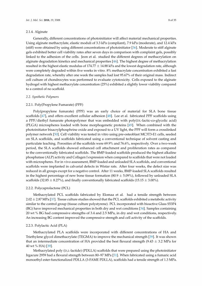
Generally, different concentrations of photoinitiator will affect material mechanical properties.Using alginate methacrylate, elastic moduli of 3.3 kPa (compliant), 7.9 kPa (moderate), and 12.4 kPa(stiff) were obtained by using different concentrations of photoinitiator [36]. Moderate to stiff alginategels exhibited better cell viability rates after seven days in comparison with complaint gels, possiblylinked to the adhesion of the cells. Jeon et al. studied the different degrees of methacrylation onalginate degradation kinetics and mechanical properties [46]. The highest degree of methacrylationresulted in the highest elastic modulus of 174.77 ± 14.88 kPa and the lowest degradation rate, althoughwere completely degraded within five weeks in vitro. 8% methacrylate concentration exhibited a fastdegradation rate, whereby after one week the samples had lost 95.67% of their original mass. Indirectcell culture of chondrocytes was performed to evaluate cytotoxicity. Cells exposed to the alginatehydrogel with highest methacrylate concentration (25%) exhibited a slightly lower viability comparedto a control of no scaffold.
2.2. Synthetic Polymers
2.2.1. Poly(Propylene Fumarate) (PPF)
Poly(propylene fumarate) (PPF) was an early choice of material for SLA bone tissuescaffolds [47], and offers excellent cellular adhesion [48]. Lee et al. fabricated PPF scaffolds usinga PPF/diethyl fumarate photopolymer that was embedded with poly(DL-lactic-co-glycolic acid)(PLGA) microspheres loaded with bone morphogenetic proteins [49]. When combined with thephotoinitiator bisacrylphosphrine oxide and exposed to a UV light, the PPF will form a crosslinkedpolymer network [50]. Cell viability was tested in vitro using pre-osteoblast MC3T3-E1 cells, seededon SLA scaffolds, and scaffolds fabricated using a conventional technique of solvent casting andparticulate leaching. Porosities of the scaffolds were 69.9% and 76.6%, respectively. Over a two-weekperiod, the SLA scaffolds showed enhanced cell attachment and proliferation rates as comparedto the conventionally fabricated scaffolds. The BMP-loaded scaffolds produced the highest alkalinephosphatase (ALP) activity and Collagen I expression when compared to scaffolds that were not loadedwith microspheres. For in vivo assessment, BMP-loaded and unloaded SLA scaffolds, and conventionalscaffolds were implanted in calvarial defects in Wistar rats. After four weeks, the defect size wasreduced in all groups except for a negative control. After 11 weeks, BMP-loaded SLA scaffolds resultedin the highest percentage of new bone tissue formation (80.9 ± 5.09%), followed by unloaded SLAscaffolds (32.85 ± 8.27%), and finally conventionally fabricated scaffolds (15.15 ± 3.00%).
2.2.2. Polycaprolactone (PCL)
Methacrylated PCL scaffolds fabricated by Elomaa et al. had a tensile strength between2.02 ± 2.87 MPa [37]. Tissue culture studies showed that the PCL scaffolds exhibited a metabolic activitysimilar to the control group (tissue culture polystyrene). PCL incorporated with bioactive Glass S53P4(BG) have improved mechanical properties in both dry and wet conditions [34]. Samples containing20 wt % BG had compressive strengths of 3.4 and 2.5 MPa, in dry and wet conditions, respectively.An increasing BG content improved the compressive strength and cell activity of the scaffolds.
2.2.3. Polylactic Acid (PLA)
Methacrylated PLA scaffolds were incorporated with different concentrations of HA andTriethylene glycol dimethacrylate (TEGMA) to improve the mechanical strength [39]. It was shownthat an intermediate concentration of HA provided the best flexural strength (9.43 ± 3.2 MPa for40 wt % HA) [39].
Methacrylated poly (D,L-lactide) (PDLLA) scaffolds that were prepared using the photoinitiatorIrgacure 2959 had a flexural strength between 80–97 MPa [51]. When fabricated using a fumaric acidmonoethyl ester-functionalized PDLLA (3-FAME PDLLA), scaffolds had a tensile strength of 1.3 MPa.
Int. J. Mol. Sci. 2018, 19, 3308 9 of 35
With the addition of N-vinyl-2-pyrrolidone (NVP), the tensile strength increased to 56 ± 10 MPa.In vitro tests suggest that the mechanical properties and water uptake can be tailored by changing theNVP content without any negative consequences on the cell adhesion properties, and therefore cansuccessfully be used for improving the mechanical properties of PDLLA in situ [52].
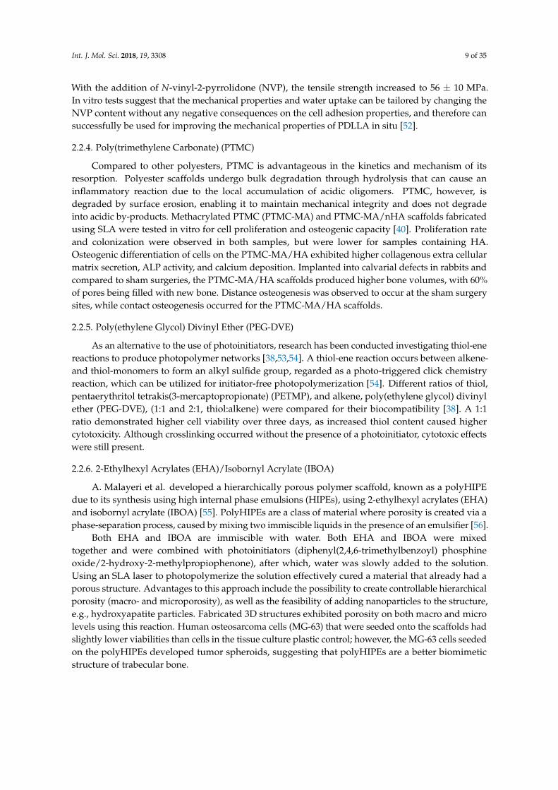
2.2.4. Poly(trimethylene Carbonate) (PTMC)
Compared to other polyesters, PTMC is advantageous in the kinetics and mechanism of itsresorption. Polyester scaffolds undergo bulk degradation through hydrolysis that can cause aninflammatory reaction due to the local accumulation of acidic oligomers. PTMC, however, isdegraded by surface erosion, enabling it to maintain mechanical integrity and does not degradeinto acidic by-products. Methacrylated PTMC (PTMC-MA) and PTMC-MA/nHA scaffolds fabricatedusing SLA were tested in vitro for cell proliferation and osteogenic capacity [40]. Proliferation rateand colonization were observed in both samples, but were lower for samples containing HA.Osteogenic differentiation of cells on the PTMC-MA/HA exhibited higher collagenous extra cellularmatrix secretion, ALP activity, and calcium deposition. Implanted into calvarial defects in rabbits andcompared to sham surgeries, the PTMC-MA/HA scaffolds produced higher bone volumes, with 60%of pores being filled with new bone. Distance osteogenesis was observed to occur at the sham surgerysites, while contact osteogenesis occurred for the PTMC-MA/HA scaffolds.
2.2.5. Poly(ethylene Glycol) Divinyl Ether (PEG-DVE)
As an alternative to the use of photoinitiators, research has been conducted investigating thiol-enereactions to produce photopolymer networks [38,53,54]. A thiol-ene reaction occurs between alkene-and thiol-monomers to form an alkyl sulfide group, regarded as a photo-triggered click chemistryreaction, which can be utilized for initiator-free photopolymerization [54]. Different ratios of thiol,pentaerythritol tetrakis(3-mercaptopropionate) (PETMP), and alkene, poly(ethylene glycol) divinylether (PEG-DVE), (1:1 and 2:1, thiol:alkene) were compared for their biocompatibility [38]. A 1:1ratio demonstrated higher cell viability over three days, as increased thiol content caused highercytotoxicity. Although crosslinking occurred without the presence of a photoinitiator, cytotoxic effectswere still present.
2.2.6. 2-Ethylhexyl Acrylates (EHA)/Isobornyl Acrylate (IBOA)
A. Malayeri et al. developed a hierarchically porous polymer scaffold, known as a polyHIPEdue to its synthesis using high internal phase emulsions (HIPEs), using 2-ethylhexyl acrylates (EHA)and isobornyl acrylate (IBOA) [55]. PolyHIPEs are a class of material where porosity is created via aphase-separation process, caused by mixing two immiscible liquids in the presence of an emulsifier [56].
Both EHA and IBOA are immiscible with water. Both EHA and IBOA were mixedtogether and were combined with photoinitiators (diphenyl(2,4,6-trimethylbenzoyl) phosphineoxide/2-hydroxy-2-methylpropiophenone), after which, water was slowly added to the solution.Using an SLA laser to photopolymerize the solution effectively cured a material that already had aporous structure. Advantages to this approach include the possibility to create controllable hierarchicalporosity (macro- and microporosity), as well as the feasibility of adding nanoparticles to the structure,e.g., hydroxyapatite particles. Fabricated 3D structures exhibited porosity on both macro and microlevels using this reaction. Human osteosarcoma cells (MG-63) that were seeded onto the scaffolds hadslightly lower viabilities than cells in the tissue culture plastic control; however, the MG-63 cells seededon the polyHIPEs developed tumor spheroids, suggesting that polyHIPEs are a better biomimeticstructure of trabecular bone.

Int. J. Mol. Sci. 2018, 19, 3308 10 of 35
2.3. Bioceramics
Tricalcium Phosphate/Hydroxyapatite
Bioceramic and bioceramic/PCL scaffolds were designed and fabricated by Seol et al. [35].Ceramics are not photocurable and they require a photocurable resin to bind the particles together, inthis instance, HA and TCP (7:3 wt %). The bioceramics slurry was mixed with a photocurable resin(FA1260T; SKCytec, Seoul, Korea), at a 20% volume ratio of bioceramics to resin. After curing with SLAand the removal of the uncured solution, the scaffolds were sintered at 1400 ◦C to remove the solidifiedphotocurable resin and fuse the bioceramic particles together. For bioceramic/polymer scaffolds, PCLsolution was used to infiltrate the scaffolds after sintering. The average compressive strengths were2.04 ± 0.12 MPa for pure bioceramic and 4.55 ± 0.21 MPa for bioceramic/PCL. Cell viability of thebioceramic/polymer scaffolds was less than pure bioceramic scaffolds. However, bioceramic/PCLscaffolds exhibited a higher expression of osteogenic markers, both in normal and osteogenic mediums.
3. Selective Laser Sintering
Selective laser sintering (SLS) uses a high-powered carbon dioxide laser to fuse small particles ofpolymer powder, as depicted in Figure 4. Most commonly used materials in SLS are the polymer PCL,calcium phosphates, or composites of polymer and bioceramic [57]. Fabrication of ceramics using SLSis generally considered difficult due to the fast heating and cooling rates that are induced by the hightemperature laser, which produces scaffolds that are usually fragile [58,59]. The main advantage of SLSis its capability of producing highly detailed prints with thin walls [60]. However, in comparison to theother AM techniques, it has a poor dimensional accuracy of just 150–180 µm [57]. Other issues that areassociated with SLS include the inability to incorporate growth factors and cells during printing [57],as well as shrinking and warping of the scaffold due to thermal distortion [58]. A variety of materialscan be used for SLS (summarized in Table 2), however natural polymers cannot be utilized in thistechnique because of the high temperatures that are generated by the laser.
Int. J. Mol. Sci. 2018, 18, x FOR PEER REVIEW 10 of 35
2.3. Bioceramics
Tricalcium Phosphate/Hydroxyapatite
Bioceramic and bioceramic/PCL scaffolds were designed and fabricated by Seol et al. [35].
Ceramics are not photocurable and they require a photocurable resin to bind the particles together,
in this instance, HA and TCP (7:3 wt %). The bioceramics slurry was mixed with a photocurable resin
(FA1260T; SKCytec, Seoul, Korea), at a 20% volume ratio of bioceramics to resin. After curing with
SLA and the removal of the uncured solution, the scaffolds were sintered at 1400 °C to remove the
solidified photocurable resin and fuse the bioceramic particles together. For bioceramic/polymer
scaffolds, PCL solution was used to infiltrate the scaffolds after sintering. The average compressive
strengths were 2.04 ± 0.12 MPa for pure bioceramic and 4.55 ± 0.21 MPa for bioceramic/PCL. Cell
viability of the bioceramic/polymer scaffolds was less than pure bioceramic scaffolds. However,
bioceramic/PCL scaffolds exhibited a higher expression of osteogenic markers, both in normal and
osteogenic mediums.
3. Selective Laser Sintering
Selective laser sintering (SLS) uses a high-powered carbon dioxide laser to fuse small particles
of polymer powder, as depicted in Figure 4. Most commonly used materials in SLS are the polymer
PCL, calcium phosphates, or composites of polymer and bioceramic [57]. Fabrication of ceramics
using SLS is generally considered difficult due to the fast heating and cooling rates that are induced
by the high temperature laser, which produces scaffolds that are usually fragile [58,59]. The main
advantage of SLS is its capability of producing highly detailed prints with thin walls [60]. However,
in comparison to the other AM techniques, it has a poor dimensional accuracy of just 150–180 μm
[57]. Other issues that are associated with SLS include the inability to incorporate growth factors and
cells during printing [57], as well as shrinking and warping of the scaffold due to thermal distortion
[58]. A variety of materials can be used for SLS (summarized in Table 2), however natural polymers
cannot be utilized in this technique because of the high temperatures that are generated by the laser.
Figure 4. Schematic of selective laser sintering (SLS) process. A laser source sinters/melts the top layer
of powder in a powder bed in a predetermined pattern. The powder bed is lowered in height and a
fresh layer of powder is positioned on top via a leveling roller. The process is then repeated.
Figure 4. Schematic of selective laser sintering (SLS) process. A laser source sinters/melts the top layerof powder in a powder bed in a predetermined pattern. The powder bed is lowered in height and afresh layer of powder is positioned on top via a leveling roller. The process is then repeated.

Int. J. Mol. Sci. 2018, 19, 3308 11 of 35
Table 2. Summary of SLS Scaffold Properties.
Material Scaffold Compressive Strength (MPa) Porosity (%) Biological Response References
Magnesium silicate (Mg2SiO4) 40.29 ± 1.32 MPa / / [61]
β-TCP/ZnO 17.89 MPa with 2.5 wt % ZnO 56.8 MG-63 cells indicated better attachment and proliferationwith increased ZnO [62]
HA/β-TCP 18.35 MPa with 30 wt % β-TCP ~61 MG-63 cells exhibited better attachment and morphology onscaffolds with 30 wt % and 50 wt % [63]
PCL 2.3 MPa 50 Implanted in minipigs, exhibited full healing in 3 months [64]
PCL/β-TCP 6 MPa * with 10 wt % β-TCP 68 Pure β-TCP exhibited better ingrowth thanpolymer/ceramic composite [65]
PCL/HA 3.17 MPa with 15 wt % HA 70.31 PCL/HA scaffolds exhibited better bioactivity than pure PCLafter 28 days [66]
PHBV/CP 0.55 MPa with 15 wt % CP 62.6 ± 1.2 The incorporation of CP nanoparticles significantly improvedcell proliferation and alkaline phosphatase activity [67]
PLLA/CHA Over 0.6 MPa with 10 wt % CHA 66.8 ± 2.5 Cellular response similar to pure PLLA [67]
* Effective modulus. Abbreviations: β-TCP: β-tricalcium phosphate, HA: hydroxyapatite, PCL: polycaprolactone, PHBV: poly(hydroxybutyrate-co-hydroxyvalerate), CP: calciumphosphate, PLLA: poly(L-lactic acid), CHA: carbonated hydroxyapatite.

Int. J. Mol. Sci. 2018, 19, 3308 12 of 35
3.1. Bioceramics
3.1.1. Magnesium Silicate
Magnesium silicate (Mg2SiO4), also known as forsterite, is a bioceramic that exhibits goodbiocompatibility and mechanical strength, however it suffers from poor bioactivity and a slowdegradation rate. To improve its degradative and bioactive properties, Sun et al., combined forsteritewith a calcium inosilicate, wollastonite (CaSiO3) [61]. Using SLS with a laser power and spot diameterof 8.5 W and 1 mm, scaffolds were fabricated that had a compressive strength of 29.81 MPa with0 wt % wollastonite, which increased to 40.29 ± 1.32 MPa with the inclusion of 20 wt % wollastonite.Faster degradation and cell proliferation rates were observed with scaffolds containing 20 wt % CaSiO3.
3.1.2. Tricalcium Phosphate (TCP)
In vitro studies have shown great biocompatibility and proper degradation of both HA [68] andβ-TCP [69] SLS fabricated scaffolds. β-TCP is mostly used in low to non-load-bearing applications dueto its brittle nature. The addition of oxide-based dopant increases the mechanical strength and lowersits degradation rate [62]. In a study that was conducted by Feng et al., β-TCP was doped with differentproportions of Zinc oxide, as Zn has a proliferative effect with osteoblastic cells and an inhibitive effectwith osteoclastic cells [62]. Scaffolds that were fabricated using a laser power and spot diameter of12 W and 1.2 mm, increased in compressive strength from 3.01 MPa for pure β-TCP to 17.89 MPafor TCP with 2.5 wt % ZnO. Scaffolds with 2.5 wt % ZnO exhibited optimal mechanical strength andbiocompatibility when compared to other concentrations.
3.1.3. Hydroxyapatite (HA)
Another study by Shuai et al. was conducted to examine the effects of HA incorporated withβ-TCP via SLS. Fracture toughness of HA and β-TCP are 0.83 and 0.98 MPa, respectively [63].A maximum fracture toughness of 1.33 MPa and compressive strength of 18.35 MPa were recordedwith the ratio of 30:70 β-TCP/HA, however better degradation kinetics were observed for scaffoldswith a higher β-TCP content [63].
3.2. Polymers
3.2.1. Polycaprolactone (PCL)
PCL is commonly used in SLS because of its low melting (59–64 ◦C) and glass-transitiontemperatures (–60 ◦C) that make it easily processable [70]. Scaffolds were fabricated using a laserpower and spot diameter of 4.1 W and 450 µm. Ultimate compressive strengths were dependent onscaffold design, where the highest compressive strength reported was 10 ± 0.62 MPa for a scaffoldporosity of >50% [71]. Another PCL scaffold with a compressive strength of 2.3 MPa and 50% porositywas implanted into minipigs. Bone ingrowth and cartilage ingrowth on the articular surface wereobserved and after 3 months the defects had completely healed [64].
Combined with bioceramic particles, SLS fabricated PCL scaffolds show further potential forbone tissue applications [60,72–74]. In vivo implantation with 15 wt % nHA, developed greater boneingrowth in comparison to pure PCL and a sham surgery [66]. The inclusion of β-TCP reportedlyincreased the mechanical strength of PCL scaffolds, increasing the modulus from 2.0 to 3.0 MPa,however in vivo results showed that in comparison to a pure β-TCP scaffold, there was less bonyingrowth [65].
3.2.2. Poly(hydroxybutyrate) (PHB)
Poly(hydroxybutyrate-co-hydroxyvalerate) (PHBV) scaffolds and PHBV/TCP/HA scaffolds werefabricated using SLS, and a laser power of 14 W for pure PHBV scaffolds and 15 W for PHBV/TCP/HA.Compressive strength for the PHBV scaffolds increased from 0.475 to 0.55 MPa with the incorporation

Int. J. Mol. Sci. 2018, 19, 3308 13 of 35
of TCP/HA. Both scaffolds exhibited good cell viability and ALP activity, with slightly better resultsbeing recorded with the incorporation of TCP/HA nanoparticles [75].
4. Powder Bed Inkjet Printing
In powder bed inkjet printing, droplets of dilute solutions or biomaterials are dispensed, driveneither by thermal or piezoelectric processes into a powder bed. The prinited ink acts as a binder solutionto a bulk material positioned within the powder bed [76,77], as shown in Figure 5. Thermal printingprocesses create a localized temperature between 100 to 300 ◦C to nucleate a bubble and ejectdroplets [78,79]. Disadvantages of using thermal inkjet printing include the effect of shear and thermalstresses on natural polymer inks, as well as an inconsistent droplet volume [69,71]. In piezoelectrictechnology, drops are generated by pressure or accoustic waves that are produced via a piezoelectricactuator [24,78]. Advantages of piezo inkjet printing include its low cost and the ability to print alarge variety of materials with the choice of polar and non-polar solvents. The main disadvantage is arequirement for low concentration inks, as high viscosities, which are caused by concentrated inks,dissipate accoustic and pressure waves before a droplet can be ejected [80].
Int. J. Mol. Sci. 2018, 18, x FOR PEER REVIEW 13 of 35
the incorporation of TCP/HA. Both scaffolds exhibited good cell viability and ALP activity, with
slightly better results being recorded with the incorporation of TCP/HA nanoparticles [75].
4. Powder Bed Inkjet Printing
In powder bed inkjet printing, droplets of dilute solutions or biomaterials are dispensed, driven
either by thermal or piezoelectric processes into a powder bed. The prinited ink acts as a binder
solution to a bulk material positioned within the powder bed [76,77], as shown in Figure 5. Thermal
printing processes create a localized temperature between 100 to 300 °C to nucleate a bubble and eject
droplets [78,79]. Disadvantages of using thermal inkjet printing include the effect of shear and
thermal stresses on natural polymer inks, as well as an inconsistent droplet volume [69,71]. In
piezoelectric technology, drops are generated by pressure or accoustic waves that are produced via
a piezoelectric actuator [24,78]. Advantages of piezo inkjet printing include its low cost and the ability
to print a large variety of materials with the choice of polar and non-polar solvents. The main
disadvantage is a requirement for low concentration inks, as high viscosities, which are caused by
concentrated inks, dissipate accoustic and pressure waves before a droplet can be ejected [80].
Figure 5. Schematic of Two Different Inkjet Printing Mechanisms over a powder bed: 1. Thermal-
based, 2. Piezoelectric-based. The inkjet printheads dispense a binding solution to the powder bed
below. The powder bed is lowered in height and a fresh layer of powder is positioned on top via a
leveling roller. The process is then repeated.
The use of powder bed inkjet printing in the production of bone scaffolds is advantageous due
to the variety of materials that can be used, limited only in that the material must be in a powder
form. Bone grafts manufactured with this technique have shown promising results, ranging from
their mechanical properties (Table 3) to a successful clinical trial [81–83].
Figure 5. Schematic of Two Different Inkjet Printing Mechanisms over a powder bed: 1. Thermal-based,2. Piezoelectric-based. The inkjet printheads dispense a binding solution to the powder bed below.The powder bed is lowered in height and a fresh layer of powder is positioned on top via a levelingroller. The process is then repeated.
The use of powder bed inkjet printing in the production of bone scaffolds is advantageous dueto the variety of materials that can be used, limited only in that the material must be in a powderform. Bone grafts manufactured with this technique have shown promising results, ranging from theirmechanical properties (Table 3) to a successful clinical trial [81–83].
Int. J. Mol. Sci. 2018, 19, 3308 14 of 35
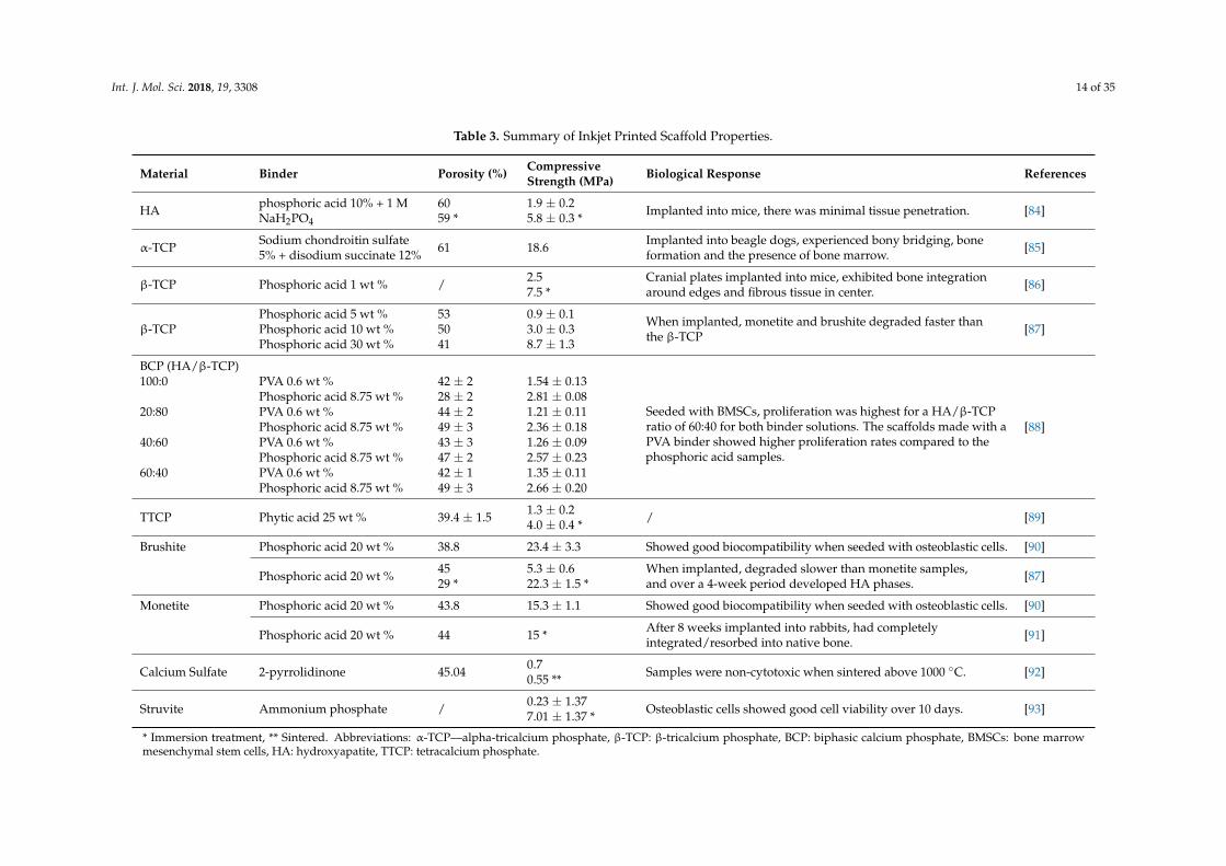
Table 3. Summary of Inkjet Printed Scaffold Properties.
Material Binder Porosity (%) CompressiveStrength (MPa) Biological Response References
HA phosphoric acid 10% + 1 MNaH2PO4
6059 *
1.9 ± 0.25.8 ± 0.3 * Implanted into mice, there was minimal tissue penetration. [84]
α-TCP Sodium chondroitin sulfate5% + disodium succinate 12% 61 18.6 Implanted into beagle dogs, experienced bony bridging, bone
formation and the presence of bone marrow. [85]
β-TCP Phosphoric acid 1 wt % / 2.57.5 *
Cranial plates implanted into mice, exhibited bone integrationaround edges and fibrous tissue in center. [86]
β-TCPPhosphoric acid 5 wt %Phosphoric acid 10 wt %Phosphoric acid 30 wt %
535041
0.9 ± 0.13.0 ± 0.38.7 ± 1.3
When implanted, monetite and brushite degraded faster thanthe β-TCP [87]
BCP (HA/β-TCP)100:0 PVA 0.6 wt % 42 ± 2 1.54 ± 0.13
Seeded with BMSCs, proliferation was highest for a HA/β-TCPratio of 60:40 for both binder solutions. The scaffolds made with aPVA binder showed higher proliferation rates compared to thephosphoric acid samples.
Phosphoric acid 8.75 wt % 28 ± 2 2.81 ± 0.0820:80 PVA 0.6 wt % 44 ± 2 1.21 ± 0.11
Phosphoric acid 8.75 wt % 49 ± 3 2.36 ± 0.18 [88]40:60 PVA 0.6 wt % 43 ± 3 1.26 ± 0.09
Phosphoric acid 8.75 wt % 47 ± 2 2.57 ± 0.2360:40 PVA 0.6 wt % 42 ± 1 1.35 ± 0.11
Phosphoric acid 8.75 wt % 49 ± 3 2.66 ± 0.20
TTCP Phytic acid 25 wt % 39.4 ± 1.5 1.3 ± 0.24.0 ± 0.4 * / [89]
Brushite Phosphoric acid 20 wt % 38.8 23.4 ± 3.3 Showed good biocompatibility when seeded with osteoblastic cells. [90]
Phosphoric acid 20 wt % 4529 *
5.3 ± 0.622.3 ± 1.5 *
When implanted, degraded slower than monetite samples,and over a 4-week period developed HA phases. [87]
Monetite Phosphoric acid 20 wt % 43.8 15.3 ± 1.1 Showed good biocompatibility when seeded with osteoblastic cells. [90]
Phosphoric acid 20 wt % 44 15 * After 8 weeks implanted into rabbits, had completelyintegrated/resorbed into native bone. [91]
Calcium Sulfate 2-pyrrolidinone 45.04 0.70.55 ** Samples were non-cytotoxic when sintered above 1000 ◦C. [92]
Struvite Ammonium phosphate / 0.23 ± 1.377.01 ± 1.37 * Osteoblastic cells showed good cell viability over 10 days. [93]
* Immersion treatment, ** Sintered. Abbreviations: α-TCP—alpha-tricalcium phosphate, β-TCP: β-tricalcium phosphate, BCP: biphasic calcium phosphate, BMSCs: bone marrowmesenchymal stem cells, HA: hydroxyapatite, TTCP: tetracalcium phosphate.
Int. J. Mol. Sci. 2018, 19, 3308 15 of 35
4.1. Bioceramics
4.1.1. Hydroxyapatite
Powder printed pure HA scaffolds have been shown to offer excellent biocompatibility [94],however are usually associated with a brittle structure. To improve the brittle nature of HA structures,Stevanovic et al. used polymer infiltration after sintering [95]. The mechanical properties wereimproved as the polymer bridges any cracks that form in the HA scaffold when the structure is underload. The HA scaffolds were initially fabricated using an acidic solution of phosphoric acid (15 wt %)and citric acid (10 wt %), which were then sintered for 1 h at 1425 ◦C. The scaffolds were then infiltratedwith either gelatin, PCL or PVA. However, each layer of applied polymer reduced scaffold porosity,ranging from 2% reduction for PCL, up to 60% for gelatin. Polymer infiltration improved compressivestrengths from 0.8 MPa, up to 3.7 MPa, 1.03 MPa, and 0.9 MPa after the application of gelatin, PVA, orPCL, respectively.
Another way of improving the mechanical properties of HA scaffolds has been to use a distributionof different particle sizes. Using an optimal particle size ratio increases the total surface contactbetween neighboring bioceramic particles, thereby improving the fusion of the particles duringsintering. Using powder bed inkjet printing and a binder that is composed of 20 wt % dextrin and2.5 wt % saccharose, to produce scaffolds that were then sintered at 1250 ◦C; a bimodal powder witha large particle size between 63–89 µm contributing to >75 wt % gave the best compressive strength(13.7 MPa) [96].
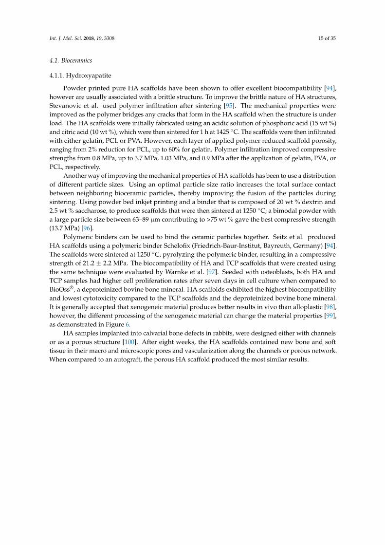
Polymeric binders can be used to bind the ceramic particles together. Seitz et al. producedHA scaffolds using a polymeric binder Schelofix (Friedrich-Baur-Institut, Bayreuth, Germany) [94].The scaffolds were sintered at 1250 ◦C, pyrolyzing the polymeric binder, resulting in a compressivestrength of 21.2 ± 2.2 MPa. The biocompatibility of HA and TCP scaffolds that were created usingthe same technique were evaluated by Warnke et al. [97]. Seeded with osteoblasts, both HA andTCP samples had higher cell proliferation rates after seven days in cell culture when compared toBioOss®, a deproteinized bovine bone mineral. HA scaffolds exhibited the highest biocompatibilityand lowest cytotoxicity compared to the TCP scaffolds and the deproteinized bovine bone mineral.It is generally accepted that xenogeneic material produces better results in vivo than alloplastic [98],however, the different processing of the xenogeneic material can change the material properties [99],as demonstrated in Figure 6.
HA samples implanted into calvarial bone defects in rabbits, were designed either with channelsor as a porous structure [100]. After eight weeks, the HA scaffolds contained new bone and softtissue in their macro and microscopic pores and vascularization along the channels or porous network.When compared to an autograft, the porous HA scaffold produced the most similar results.

Int. J. Mol. Sci. 2018, 19, 3308 16 of 35
Int. J. Mol. Sci. 2018, 18, x FOR PEER REVIEW 16 of 35
Figure 6. Comparison of two different xenogeneic bone graft materials: (A) sintered xenograft
(Cerabone®) and (B) non-sintered xenograft (BioOss®). For example, xenograft (A) has a rougher
surface in comparison to xenograft (B).
4.1.2. Tetracalcium Phosphate (TTCP)
Tetracalcium phosphate (Ca4(PO4)2O) (TTCP) is more reactive than other calcium phosphates
(CPs), and it is a common component of bone cements. TTCP scaffolds with a macro porosity of 39.4
± 1.5%, had a compressive strength of 1.3 ± 0.2 MPa after printing that increased to 4.0 ± 0.4 MPa after
an immersion treatment in phytic acid [89]. An immersion treatment in phytic acid enabled the
formation of harder calcium phases, such as calcium phylate, which are mechanically strong, but are
also more easily degraded and resorbed in comparison to HA. The mechanical properties of the
printed scaffolds were analyzed as the TTCP degraded in a PBS solution. After seven, 15, and 28 days,
the compressive strengths dropped to 3.6 ± 0.5 MPa, 3.1 ± 0.5 MPa, and2.8 ± 0.2 MPa, respectively
[89].
4.1.3. Dicalcium Phosphate (DCP)
Scaffolds printed without a subsequent heat treatment were produced from either brushite
(DCPD) or HA. By not including a heat treatment, vascular endothelial growth factor (VEGF) and
copper(II) ions could be included [84]. The scaffolds had a compressive strength of 22.3 ± 1.5 MPa
(DCPD) and 5.8 ± 0.3 MPa (HA). After 15 days implanted into the peritoneal cavity in mice, implants
with angiogenic inclusions had developed a vascular network spanning the device, as compared to
a 2 mm penetration for scaffolds without inclusions. The angiogenic scaffolds had a micro vessel
network lined with endothelial cells with vessels aligned parallel to pore direction.
Figure 6. Comparison of two different xenogeneic bone graft materials: (A) sintered xenograft(Cerabone®) and (B) non-sintered xenograft (BioOss®). For example, xenograft (A) has a roughersurface in comparison to xenograft (B).
4.1.2. Tetracalcium Phosphate (TTCP)
Tetracalcium phosphate (Ca4(PO4)2O) (TTCP) is more reactive than other calcium phosphates(CPs), and it is a common component of bone cements. TTCP scaffolds with a macro porosity of39.4 ± 1.5%, had a compressive strength of 1.3 ± 0.2 MPa after printing that increased to 4.0 ± 0.4 MPaafter an immersion treatment in phytic acid [89]. An immersion treatment in phytic acid enabledthe formation of harder calcium phases, such as calcium phylate, which are mechanically strong,but are also more easily degraded and resorbed in comparison to HA. The mechanical propertiesof the printed scaffolds were analyzed as the TTCP degraded in a PBS solution. After seven, 15,and 28 days, the compressive strengths dropped to 3.6 ± 0.5 MPa, 3.1 ± 0.5 MPa, and2.8 ± 0.2 MPa,respectively [89].
4.1.3. Dicalcium Phosphate (DCP)
Scaffolds printed without a subsequent heat treatment were produced from either brushite (DCPD)or HA. By not including a heat treatment, vascular endothelial growth factor (VEGF) and copper(II)ions could be included [84]. The scaffolds had a compressive strength of 22.3 ± 1.5 MPa (DCPD)and 5.8 ± 0.3 MPa (HA). After 15 days implanted into the peritoneal cavity in mice, implants withangiogenic inclusions had developed a vascular network spanning the device, as compared to a 2 mmpenetration for scaffolds without inclusions. The angiogenic scaffolds had a micro vessel networklined with endothelial cells with vessels aligned parallel to pore direction.

Int. J. Mol. Sci. 2018, 19, 3308 17 of 35
Two of the most commonly used DCPs are brushite and monetite. The mechanical properties ofbrushite scaffolds are slightly better than that of monetite scaffolds. In a study that was performedby Klammert et al., brushite scaffolds that were fabricated by printing 20 wt % phosphoric acid ontoTCP powder had a compressive strength of 23.4 ± 3.3 MPa compared to 15.3 ± 1.1 MPa for printedmonetite scaffolds [90]. Seeded with osteoblastic cell line MC3T3-E1 cells, brushite demonstratedhigher cell viabilities and ALP activity than the monetite samples, however in comparison to titaniumpositive controls, both CP scaffolds gave significantly lower results.
Brushite and monetite cranial and maxillofacial implants designed to fit a cadaver skull usingCT data were shown to have a high degree of accuracy of fit [101]. The bending strength of thebrushite scaffolds was 5.2 ± 0.8 MPa with a porosity of 28.2%, whilst the monetite scaffolds had abending strength of 3.9 ± 0.5 MPa and a porosity of 34.6%. Due to its mechanical and biocompatibilityproperties, brushite may offer preferential properties for bone tissue engineering than monetite.
Monetite bone block onlay grafts with a 44% porosity and a 15 MPa compressive strengthwere implanted into the cranium of rabbits and compared to autologous bone onlay grafts [91].Histological analysis that was performed at eight weeks showed that the printed monetite blockshad completely integrated with the native bone via its resorption and subsequent replacement withbone tissue and showed signs of calcification similar to that of the calvarial bone. Overall, the printedimplants produced comparable results to that of autologous bone.
4.1.4. Tricalcium Phosphate (TCP)
Concentrations of chemical binders have been shown to control the intensity of bonding reactionsbetween TCP particles. Gbureck et al. found that increasing the concentration of the phosphoricacid binder from 5% to 30% improved the mechanical properties of TCP scaffolds from 0.9 to8.7 MPa, respectively [87]. The type of heat treatment can also change the material properties.Microwave sintering of TCP scaffolds causes increased shrinkage and therefore densification [102].A microwave sintered TCP scaffold with 500 µm designed pore sizes had a maximum compressivestrength of 10.95 ± 1.28 MPa as compared to 6.62 ± 0.67 MPa for a standard sintered TCP scaffold.
CT data can be used to improve scaffold designs and create a better fit to the defect dimensions.α-TCP cranial plates designed using CT data and printed using a binder solution of 5% sodiumchondroitin sulfate and 12% disodium succinate, were implanted into beagle dogs [85]. Blocks printedof the α-TCP that had a 61% porosity and had a compressive strength of 18.6 MPa. There was improvedbone growth for the printed α-TCP samples compared to a standard HA bone block; however, bothimplants were predominantly infiltrated by connective tissues. Poor bone growth into the HA implantwas linked to a reduced contact between the HA implant and the native bone. The HA bone block hadto be cut into shape, whereas the 3D printed scaffolds were printed to match the defect dimensions.
Doping the TCP scaffold with bioactive compounds can improve biocompatibility [103].To facilitate bone formation and faster mineralization, TCP scaffolds were doped with SrO andMgO [104]. Doping TCP with Sr and Mg ions densified the scaffolds due to substitutions within theTCP lattice. Doped TCP scaffolds with a pore size of 1000 µm achieved a compressive strength of12.01 ± 1.56 MPa as compared to 10.95 ± 1.28 MPa for pure TCP. The doped TCP scaffolds achievedfaster bone formation and developed similarities to the native tissue when implanted into rat distalfemoral defects.
TCP scaffolds doped with silica (0.5 wt %) and zinc oxide (0.25 wt %) retarded the transition of βto α phase during sintering above 1150 ◦C, resulting in significantly higher compressive strengths [105].Doped samples had a porosity of 41.04% and 27.26% and almost double the compressive strengths ofpure TCP samples. Proliferation rates of human fetal osteoblastic (hFOB) cells seeded on the dopedTCP scaffolds were significantly higher than that for pure TCP scaffolds.
Int. J. Mol. Sci. 2018, 19, 3308 18 of 35
4.1.5. Octacalcium Phosphate (OCP)
Octacalcium phosphate scaffolds can be produced using low temperature printing and they havebetter mechanical properties as compared to TCP. Komlev et al. made green TCP cranial plates byprinting a 1% phosphoric acid binder onto a TCP powder, which resulted in a compressive strength of2.5 MPa [86]. The formation of octacalcium phosphate was induced by immersing the TCP scaffoldsin ammonium phosphate solution, followed by sodium acetate solution. The octacalcium phosphatecranial plates had a compressive strength around 7.5 MPa. After implantation into rabbits, bone tissueintegrated along the edges of the implant as well as along the internal and external surfaces. However,within the central region of the plate, no osteogenesis had occurred and fibrous tissue had penetratedthe pores.
4.1.6. Calcium Polyphosphate (CPP)
Printed CPP scaffolds have shown isotropic effects due to print orientation. Shanjani et al.found that thescaffolds were 48% stronger when printed layers were stacked parallel to the appliedcompressive loads, increasing from 33.86 ± 6.32 MPa to 50.17 ± 4.74 MPa [106]. The isotropic effectswere attributed to the orientation of the powder bed particles. During the application of powderbetween printed layers, the roller action could cause the non-spherical particles to orientate withtheir larger facets parallel to the build plane. During sintering it is via the large facets that the mostpredominant interparticle connections are made, hence providing isotropic properties.
To compare the in vivo response of the printed CPP scaffolds in comparison to conventionallymade CP scaffolds, Shanjani et al. fabricated scaffolds using the above mentioned method, as well asby a conventional technique. Both methods produced scaffolds that had a ~30% porosity, and wereimplanted into the medial femoral condyle of rabbits over a six-week period [107]. All scaffoldsdemonstrated a uniform bone ingrowth and a degradation rate between 7–9%. The tissue responsedid not seem to be influenced by any isotropic effects that are caused by the print orientation. Overall,the study indicated that a similar in vivo response for both fabrication methods and therefore thesuitability of powder bed inkjet printing for the fabrication of CPP bone tissue scaffolds.
4.1.7. Biphasic Calcium Phosphate (BCP)
BCP composition will influence scaffold mechanical and biocompatibility properties, wherebyan optimum 60:40 ratio of HA to β-TCP has been reported to give the highest cell proliferation rateswhilst retaining good mechanical properties [88]. In a preclinical study, it has been shown that the60:40 biphasic composition provides excellent degradation kinetics, combining the characteristics ofboth HA and β-TCP compounds [108].
The type of binder used will influence the mechanical properties of the scaffold. Wang et al.found that BCP scaffolds held together with PVA, which acted as a physical binder between particles,were mechanically weaker than a phosphoric acid binder, which chemically bonded the particlestogether [88]. PVA binder samples had compressive strengths between 1.21–1.54 MPa, a Young’smodulus between 38–70 MPa, and a strain to failure range between 2.5–3.4%, whilst the phosphoricacid binder samples had a compressive strength range of 2.36–2.81 MPa, a Young’s modulus between100–147 MPa, and a strain to failure between 3.0–2.8%.
Inzana et al. used a low temperature fabrication of TCP scaffolds using a binder of a phosphoricacid solution containing collagen [57]. Phosphoric acid concentrations ≥8.75 wt % caused the collagento denature. Lower phosphoric acid concentrated solutions containing 1 wt % collagen produced asimilar mineral density, mineral content, and net mineralized volume when compared to an autograftwhen implanted into mid-femoral defects in mice. However, after nine weeks, neither the scaffold northe autograft had a torsional strength that is comparable to an intact murine femur (19.4 ± 5.6 N mm).

Int. J. Mol. Sci. 2018, 19, 3308 19 of 35
4.1.8. Calcium Sulfate (CS)
The temperature used during post printing heat treatments has been shown to affect themechanical and biocompatible properties of calcium sulfate scaffolds [92]. Heated to ≥1150 ◦C,CS scaffolds were shown to have the highest compressive strength (2.47 MPa) and Young’s modulus(52.11 MPa). Scaffolds that were heat treated at 300 ◦C exhibited sever toxicity (below 60% viability)due to remnants of the binder. Samples heat treated between 500–1000 ◦C were non-cytotoxic due topyrogenesis of the binder at 500 ◦C, however these scaffolds had poor mechanical properties due toinsufficient densification. Overall, samples receiving a heat treatment of 1000 ◦C and above had thebest mechanical properties and were the least cytotoxic. A porous scaffold that was sintered at 1250 ◦Chad the most idealized properties with a compressive strength of 0.55 MPa and a Young’s modulus of58.12 MPa.
Farzadi et al. found that layer thickness and print orientation were also important for mechanicalproperties of non-heat-treated scaffolds [80]. A peak compressive strength (~0.5 MPa) and Young’smodulus (~30 MPa) was measured for Scaffolds printed with a Z axis orientation, which wassignificantly higher than that of scaffolds that were printed in an X or Y orientation. Increasingthe print delay time also had an effect. Prolonging the print delay time from 50 to 300 ms increased thecompressive strengths from ~0.4 to ~0.8 MPa and Young’s modulus from ~0.6 to ~1.7 MPa.
4.1.9. Magnesium Ammonium Phosphate
Calcium phosphates bound with a chemical binder usually produce an acidic environment,whilst magnesium ammonium phosphate (struvite) (Mg3(PO4)2) scaffolds that were printed with anammonium phosphate binder produce a neutral pH reaction during manufacture [93]. After a postprinting immersion treatment, samples had a compressive strength between 2–7 MPa. MG63 cellviability on the struvite scaffold continued to increase up until day 10, however at levels significantlybelow that of the positive controls (60% of the cell culture dish viability). The lower cytocompatibilityof the struvite scaffolds may be due to the partial dissolution of the struvite powder into the cellculture medium, which caused significantly higher Mg2+ and PO4
3− ion concentration, as well assignificantly lower Ca2+ ion concentration. In a physiological environment, the surrounding fluidwould be replenished more often, which would control surrounding ion concentrations and hencethese effects might not be seen in vivo.
4.2. Synthetic Polymers
4.2.1. Poly (DL-lactide-co-glycolide) (PLGA)
PLGA scaffolds were produced using a binder of ethanol, acetone, and de-ionized water thathad a pore size of 1 mm, a porosity of 50%, a compressive strength of 7.8 ± 3.1 MPa, and a Young’smodulus of 77.2 ± 10.8 MPa [109]. The scaffolds were compared in vitro to a commercial open porepoly-lactic acid scaffold (OPLA®, Becton-Dickinson (BD) Inc., Franklin Lakes, NJ, USA) and a Collagenscaffold (Becton-Dickinson (BD) Inc.). The mechanical properties of the printed scaffold were 40 timehigher than the OPLA® scaffold and 18,000 times higher than the BD collagen scaffold. Cell viability ofhuman fetal osteoblasts at 24 h was 95%, and after 48 h 81% when compared to the controls. There wasno significant difference between the ALP activity of the cells on any of the scaffolds. In this work,cells were seeded with fibroin glue, which remained for the length of the experiment. Therefore,the similar cellular responses could be due to cellular interactions with the fibroin glue and not withthe scaffold surfaces.
PLGA scaffolds created using the same method were implanted into the periosteum and iliaccrest of rabbits [109]. When implanted into the periosteum, the scaffolds were encapsulated in adense fibrous tissue with little tissue penetration. Scaffolds that were implanted in the iliac crest wereencapsulated in a bone-like matrix that showed a high degree of integration between the scaffold andthe native bone. These results highlight the dependence of the implantation site on the tissue response.

Int. J. Mol. Sci. 2018, 19, 3308 20 of 35
Simon et al. compared scaffold architecture on bony ingrowth using four different scaffoldswith different porous architectures [110]. Implanted into rabbit trephine defects, the scaffolds werecompared to a commercial coralline scaffold (Interpore). After 16 weeks, there was no significantdifference in bone volume (around 50%) for each group, however linear bone ingrowth was significantlyhigher for the Interpore scaffold. All of the scaffolds were penetrated by fibrous tissues.
4.2.2. Poly(e-caprolactone) (PCL)
Scaffolds composed of either pure PCL or a composite with a ratio of 50:50 PCL and β-TCP, weredesigned with 1 or 2 mm sized channels [111]. Seeded with porcine bone marrow-derived progenitorcells (pBMPC), there was no deformation or shrinkage for any of the scaffolds after two weeks in cellculture. At every time point, the PCL/β-TCP scaffold with 1 mm channels had significantly highercell concentrations than the other scaffolds and it had the highest level of collagen formation.
4.3. Clinical Study
A long term clinical study has been completed using α-TCP printed facial bones and involved20 patients [81–83]. The mechanical properties of the low temperature fabricated artificial bones wasless than that of other sintered bone substitutes, however it was deemed sufficient for non-load bearingfacial bones. After one year, 18 of 21 implant sites had formed a bony union between the implant andthe native bone. The artificial bone did not change shape, although there was an average increase inthickness of 3.3%. Two adverse events were recorded during the first year, one caused by physicaltrauma, the other due to infection that had developed as a result of the patient being a carrier ofMRSA. After the first year, three further adverse events occurred, in one case, more than five yearsafter implantation. In cases where the implant failed, a gap was usually present between the artificialbone and the native bone immediately after surgery. By the time of the last follow up, all patients weresatisfied with the aesthetics of the device after implantation. Overall, the clinical trial demonstratedthe potential of powder bed inkjet printing for producing artificial bone implants.
5. Extrusion Printing
Extrusion printing can be split into two main techniques: the extrusion of molten material, referredto as fused deposition modelling (FDM) and the extrusion of gelling liquid material. The extrusion ofmolten materials requires the use of a thermoplastic that is usually fed to the printhead in the form ofa long filament. Within the printhead, the filament is melted to a predetermined temperature and isextruded through the nozzle. As this method requires the use of a thermoplastic, its use has generallybeen limited to PCL and PLA for the research of biodegradable bone scaffolds. The accuracy and shapeof the final structure is dependent on the speed at which the molten extruded filament cools down andhardens after it has been dispensed.
Another form of extrusion printing is based around the dispensing and gelling of liquid material.Extrusion is controlled via pressure based mechanisms, such as via a syringe or pneumatic pressure.This form of extrusion printing can use high-viscosity hydrogels (30 to 6× 10⁸ mPa·s) extruded throughmicro-sized nozzles [112,113].
Due to its fast processing speed and low startup costs, the application of this technology infabricating scaffolds has greatly increased [114]. The disadvantages of extrusion printing include lowresolution (around 200 µm [24]) and the requirement for high viscosity inks. The extrusion printingsystem can be pneumatic-based or mechanical based system, as demonstrated in Figure 7. A largevariety of biomaterials can be used for this technology (compared in Table 4), including natural andsynthetic polymers; ceramics can be printed as a paste, however are often used as low concentrationadditions to more easily printable polymeric hydrogels.

Int. J. Mol. Sci. 2018, 19, 3308 21 of 35
Table 4. Summary of Extrusion Printed Scaffold Properties.
Material Porosity (%) CompressiveStrength (MPa) Biological Response References
Pluronic F-127 hydrogel / 50 MPa / [115]
PLA 40% 45.61 MPa Metabolic activity and proliferation rate of osteosarcoma cells MG-63 did not havesignificant differences between each porosity. [116]PLA 50–60% 29.96 MPa
PLA 60 ± 1.5% 9.47 MPa Better seeding and metabolic activity with collagen/dopamine coating [117]
PLA55% 13.25 ± 1.6
Scaffolds with 66% porosity exhibited higher cell count [118]60% 9.47 ± 0.4766% 5.57 ± 0.27
PBT 62.11 ± 0.36% 10.44 ± 2.09 MPa / [119]
PLGA/PCL 69.6% 12.9 MPa Mesenchymal stem cells demonstrated good proliferation rates [120]
PCL 61 ± 1% Dry 41.9 ± 3.5 MPaWet 29.4 ± 4.0 MPa
Human fibroblasts and osteoprogenitor cells proliferated, differentiated anddeposited ECM [121]
PCL 54.9% / Cardiomyoblasts attached to the structure, although a pore size of 250µm did notallow for cells to migrate. [122]
PCL/HA/(0.2%) CNTPCL/HA
~40%57% / Higher concentrations of CNT enhanced cell adhesion and spreading of MG-63 cells [123]
TCP/AA 60/40-GOTCP/AA, 60/40
// / Over a 21-day period, human osteoblasts had secreted mineral deposits [124]
β-TCPPCL/β-TCPPLA/β-TCP
49%20 ± 2 MPa60 ± 10 MPa130 ± 20 MPa
/ [125]
Sr-HT-Gahnite66.1% 53 ± 9 MPA
/ [126]52.1% 121 ± 12 MPa48.5% 140 ± 15 MPa
AA: alginic acid, CNT: carbon nanotube, PBT: polybutylene terephthalate, PCL: polycaprolactone, PLA: polylactic acid, PLGA: poly (DL-lactide-co-glycolide), PPF: poly(propylene fumarate).

Int. J. Mol. Sci. 2018, 19, 3308 22 of 35
Int. J. Mol. Sci. 2018, 18, x FOR PEER REVIEW 20 of 35
4.2.2. Poly(e-caprolactone) (PCL)
Scaffolds composed of either pure PCL or a composite with a ratio of 50:50 PCL and β-TCP, were
designed with 1 or 2 mm sized channels [111]. Seeded with porcine bone marrow-derived progenitor
cells (pBMPC), there was no deformation or shrinkage for any of the scaffolds after two weeks in cell
culture. At every time point, the PCL/β-TCP scaffold with 1 mm channels had significantly higher
cell concentrations than the other scaffolds and it had the highest level of collagen formation.
4.3. Clinical Study
A long term clinical study has been completed using α-TCP printed facial bones and involved
20 patients [81–83]. The mechanical properties of the low temperature fabricated artificial bones was
less than that of other sintered bone substitutes, however it was deemed sufficient for non-load
bearing facial bones. After one year, 18 of 21 implant sites had formed a bony union between the
implant and the native bone. The artificial bone did not change shape, although there was an average
increase in thickness of 3.3%. Two adverse events were recorded during the first year, one caused by
physical trauma, the other due to infection that had developed as a result of the patient being a carrier
of MRSA. After the first year, three further adverse events occurred, in one case, more than five years
after implantation. In cases where the implant failed, a gap was usually present between the artificial
bone and the native bone immediately after surgery. By the time of the last follow up, all patients
were satisfied with the aesthetics of the device after implantation. Overall, the clinical trial
demonstrated the potential of powder bed inkjet printing for producing artificial bone implants.
5. Extrusion Printing
Extrusion printing can be split into two main techniques: the extrusion of molten material,
referred to as fused deposition modelling (FDM) and the extrusion of gelling liquid material. The
extrusion of molten materials requires the use of a thermoplastic that is usually fed to the printhead
in the form of a long filament. Within the printhead, the filament is melted to a predetermined
temperature and is extruded through the nozzle. As this method requires the use of a thermoplastic,
its use has generally been limited to PCL and PLA for the research of biodegradable bone scaffolds.
The accuracy and shape of the final structure is dependent on the speed at which the molten extruded
filament cools down and hardens after it has been dispensed.
Another form of extrusion printing is based around the dispensing and gelling of liquid material.
Extrusion is controlled via pressure based mechanisms, such as via a syringe or pneumatic pressure.
This form of extrusion printing can use high-viscosity hydrogels (30 to 6 × 10� mPa·s) extruded
through micro-sized nozzles [112,113].
Due to its fast processing speed and low startup costs, the application of this technology in
fabricating scaffolds has greatly increased [114]. The disadvantages of extrusion printing include low
resolution (around 200 μm [24]) and the requirement for high viscosity inks. The extrusion printing
system can be pneumatic-based or mechanical based system, as demonstrated in Figure 7. A large
variety of biomaterials can be used for this technology (compared in Table 4), including natural and
synthetic polymers; ceramics can be printed as a paste, however are often used as low concentration
additions to more easily printable polymeric hydrogels.
Figure 7. Schematic of extrusion based printing. A liquid resin is extruded in the form of a filament
into a predetermined pattern.
Figure 7. Schematic of extrusion based printing. A liquid resin is extruded in the form of a filamentinto a predetermined pattern.
5.1. Bioceramics
5.1.1. Hydroxyapatite
A comparison between low temperature fabrication (without sintering) and high temperaturefabrication (with sintering) was performed for hydroxyapatite (HA) and Polyetheretherketonecomposite scaffolds [127]. Extrusion was performed using an ink of a HA slurry mixed with aPVA/PEG binder. It was found that low-temperature extrusion exhibited a uniform microstructure,whereas after sintering, micropores developed along the internal structure of the filaments that couldbe beneficial for cellular attachment.
5.1.2. Tricalcium Phosphate (TCP)
Scaffolds for sinus augmentation procedures were fabricated using TCP and HA with a weightratio of 70/30 [128]. Extrusion was performed with a ceramic slurry, and scaffolds were subsequentlysintered at 1250 ◦C for 1 h. The scaffold had a mesh like structure with a filament diameter of300 ± 25 µm and pore size of 370 ± 25 µm, resulting in a total porosity of about 60%. Complete tissueintegration occurred after 45 days when implanted into adult sheep. The HA/TCP scaffold was welltolerated by the host tissue and it underwent a progressive process of tissue regeneration.
Scaffolds were fabricated by Boga et al. that had different ratios of tricalcium phosphate (TCP)and alginic acid (AA) (60:40, 70:30, 80:20) [124]. After printing, the AA was crosslinked by immersingthe scaffolds overnight in a 5% CaCl2 solution. The presence of AA created a bone-like structure,increasing mechanical resistance and elasticity. With increased ceramic content, the scaffolds becamebrittle and displayed poor mechanical resistance. By incorporating the scaffolds with graphene oxide(GO), the Young’s modulus of scaffolds with a 60:40 TCP:AA ratio, increased from 154.4 ± 8.7 MPa to188.3 ± 18.5 MPa. The addition of GO also controlled the swelling profile of the scaffold that had alarge swelling ratio, which could otherwise lead to compressive pressures on the surrounding tissueand be a source of pain for the patient [124,129].
Martinez-Vazquez et al. used polymer infiltration to improve the mechanical strength of β-TCPscaffolds [125]. A β-TCP slurry was combined with Darvan® C as a dispersant, and hydroxypropylmethylcellulose as a thickening agent. The scaffolds were subsequently sintered at 1200 ◦C for 1 h.Using a polymer melt, the scaffolds were infiltrated with either PCL or PLA, increasing the compressivestrength of the β-TCP scaffold from 20 ± 2 MPa, to 60 ± 10 MPa, and 130 ± 20 MPa for a PCL andPLA coating, respectively.
Mandibular defects in rabbits were treated with β-TCP scaffolds with a 330 µm pore size [130].For extrusion, a gel was prepared out of β-TCP powder, Darvan® A as a dispersant, hydroxypropyl toincrease viscosity, and polyethylenimine as a gelation agent. Scaffolds were sintered to burn the organiccomponent out and to densify the structure. Printed samples showed excellent integration, with bonyingrowth occurring from both defect walls. A highly cellular and vascularized bone structure wasobserved in direct contact with the scaffold.

Int. J. Mol. Sci. 2018, 19, 3308 23 of 35
5.1.3. Strontium (Sr) Composites
Strontium is an important factor for maintaining human tissue function, especially for bonedown-regulating osteoclast and up-regulating osteoblast activity and it is involved in mineralizationof new bone [131–133]. Deng et al. fabricated scaffolds from Sr5(PO4)2SiO4 (SPS) blended with sodiumalginate, that after fabrication were sintered at 1450 ◦C to remove the alginate [134]. The scaffoldswere implanted into osteochondral defects in rabbits. When compared to TCP scaffolds, SPS scaffoldsproduced higher proliferation rates and promoted greater subchondral bone regeneration.
To provide a highly porous structure whilst maintaining mechanical properties, Entezari et al.designed Sr-HT-Gahnite scaffolds with a hexagonal architecture [135]. With 50% porosity, the hexagonalarchitecture provided the scaffold with a compressive strength of 180 MPa, this was up to 42 MPahigher than scaffolds fabricated with conventional architectures. The structure was even able toproduce a compressive strength of 90 MPa with 70% porosity.
5.2. Synthetic Polymers
5.2.1. Polylactic Acid (PLA)
Gregor et al. compared the effect of porosity on mechanical properties of printed PLA scaffoldsusing a fused deposition modelling technique [116]. Scaffolds were fabricated with 30% and50% porosity with respective pore sizes of 350 and 700 µm. The 30% porosity scaffold had acompressive Young’s modulus of 45.61 ± 11.80 MPa, which decreased to 29.96 ± 14.03 MPa with a50% porosity. Although the higher porosity had a lower modulus, it promoted the greater proliferationand osteoconduction of osteosarcoma cells.
Grémare et al. also investigated the effect of pore size on scaffolds that were fabricated from PLAusing FDM [136]. Three pore sizes were produced: 150, 200, and 250 µm. No significant differencesin the ultimate tensile strength was observed between the three pore sizes, averaging around 8 N.Human bone marrow stromal cells (HBMSCs) that were seeded onto the scaffolds showed similar highcell viabilities.
The effect of increasing the strut spacing was investigated by Teixeira et al. [118]. Using anFDM printer, PLA scaffolds were printed with 0.8, 1.0, and 1.2 mm spacing between the struts,resulting in respective porosities of 55%, 60%, and 66%, and mechanical strengths of 13.25 ± 1.6 MPa,9.47 ± 0.47 MPa, and 5.57 ± 0.27 MPa. Teixeira et al. also fabricated surface functionalized PLAscaffolds by coating them with collagen and polydopamine [117]. Seeded with porcine bone marrowstem cells, the functionalized scaffolds demonstrated better seeding efficiency and higher metabolicactivity after seven days than that of the non-functionalized scaffolds.
Poly(L-lactic acid) (PLLA) combined with multiwalled carbon nanotubes (MWCNTs) enhancedscaffold mechanical properties [137]. PLLA/MWCNTs composite scaffolds with porosities between65–70% were fabricated while using a pressure-assisted microsyringe. Elastic modulus increased withincreasing MWCNTs concentration, up to 6.25 mg/mL, above which, the elastic modulus decreasedrapidly. Scaffolds supported osteoblastic proliferation and activity in in vitro cell culture.
5.2.2. Poly(DL-lactide-co-glycolide) (PLGA)
Kim et al. fabricated a PLGA/PCL scaffold using multi-head deposition system (MHDS) for amore rapid fabrication than with a single head printer [120]. The PLGA/PCL scaffold had a uniformpore size of 600 µm and the height of 200 µm. PLGA was blended with PCL to improve its brittlestructure and poor mechanical properties, with final scaffold having 69.6% porosity and a compressivemodulus of 12.9 MPa.

Int. J. Mol. Sci. 2018, 19, 3308 24 of 35
5.2.3. Poly(e-caprolactone) (PCL)
Hutmacher et al., also performed mechanical testing on polycaprolactone (PCL) scaffoldsfabricated with a porosity of 61% [121]. The compressive strength for the scaffold was 41.9 ± 3.5 MPa,however when soaked in phosphate buffer solution for one day, this dropped to 29.4 ± 4.0 MPa [121].
PCL scaffolds implanted in vivo have shown promising results. PCL scaffolds with a poresize of 500 µm and a porosity of 51.80% were implanted into critical sized bony defects in rabbitcalvarium [138]. New bone formation was more prolific on the PCL scaffold as compared to a shamsurgery control site. Only the porous area of the scaffold was able to regenerate with new bone over aperiod of 12 weeks, as the PCL degradation rate did not match the bone regeneration.
To treat an early stage of femoral head osteonecrosis, Kawai et al. have fabricated functionallygraded scaffolds made of PCL and β-TCP [139]. The scaffolds were fabricated using FDM and a feeder“ink” filament consisting of both PCL and β-TCP. The scaffolds had a graduated porosity: 59.5 ± 1.2%in the middle, and 16.4 ± 1.7% in the proximal region, designed to closely mimic the anatomicalporosity of a femoral head. The compressive strength of samples with 60% porosity was 2.2 MPa thatincreased to 9.5 MPa with 15% porosity. Implanted in rabbit femoral heads and assessed after eightweeks, the scaffolds exhibited excellent bone ingrowth.
Nyberg et al. studied the mechanical properties and in vitro response of PCL scaffolds withdifferent mineral additives [140]. The scaffolds were fabricated with a pneumatic-based FDM printer,where the ink is melted in an ink reservoir and then extruded by pneumatic pressure. The scaffoldswere made either from pure PCL, PCL/TCP, PCL/HA, PCL with natural HA (Bio-Oss®, Princeton, NJ,USA), or PCL with decellularized bone matrix (DBM). All composites had 70:30 ratio of PCL:mineraladditives and a porosity of 60%. Compressive moduli recorded 51, 37, 83, and 32 MPa for pure PCL,PCL/TCP, PCL/HA, and PCL/DBM, respectively. Adipose-derived stem cells (ASCs) were seeded onto the scaffolds to study the in vitro osteogenic response of the composites. Calcium content increasedsignificantly for all samples, except for pure PCL and PCL/HA. Collagen 1 and osteocalcin expressionsincreased 10-fold in samples with DCB and natural HA as compared to PCL samples, suggesting thatnatural organic/inorganic and inorganic composites may be advantageous in bone tissue engineering.
To enhance compressive strengths, Goncalves et al. combined hydroxyapatite (HA) and carbonnanotubes (CNT) in PCL [123]. Scaffolds were fabricated with interconnected pores with a size rangingbetween 450–700 µm and a total porosity of 57%. The inclusion of CNTs at 2 wt % increased thecompressive strength from 2.0 to 5.5 MPa. However, the inclusion of CNTs into a PCL-HA matrixhad limited effects on mechanical properties. A PCL-HA Scaffold (50:50 wt %) had a compressivestrength between 40–50 MPa, whilst a PCL-HA-CNT scaffold had a compressive strength of 50 MPa.The inclusion of CNTs might have had a limited effect on mechanical properties for the PCL-HAscaffold, but it has been shown that the presence of CNTs can improve protein adsorption andconsequently cell attachment [141–143].
Arafat et al. produced PCL/TCP scaffolds that were subsequently coated with either carbonatedhydroxyapatite (CHA) or a CHA-gelatin composite [144], as it has been shown to be beneficialfor scaffold/cell interaction [145]. Fabricated scaffolds had a honey comb structure with 100%interconnectivity and 65% porosity. Cultured with porcine bone marrow mesenchymal stem cells(BMSCs), the CHA-gelatin coated scaffolds had the fastest proliferation rates. The inclusion of CHAimproved cell morphology and enhanced the stimulation of osteogenic differentiation of the BMSCs.
Extruded PCL/β-TCP scaffolds were used to reconstruct maxillofacial defects in dogs [146].Scaffolds had a 500 × 100 µm pore size and 63% porosity. After seven months, the maxillary appearancewas restored and appeared the same as the healthy side, demonstrating that extruded PCL/β-TCPscaffolds can maintain anatomical uniformity and appearance and provided optimal strength andfunction when applied in vivo.
Shanjani et al. demonstrated a sequential process involving two fabrication techniques to producea hybrid scaffold made from a rigid porous PCL structure combined with a soft cured PEGDAhydrogel [147]. The rigid PCL provided the scaffold with mechanical strength, whilst the soft hydrogel

Int. J. Mol. Sci. 2018, 19, 3308 25 of 35
can be used for incorporating cells and/or growth factors. The PCL was extruded using FDM whilst thehydrogel was crosslinked using SLA and an LAP photoinitiator. The hybrid scaffold had a compressivestrength of 6 MPa. Human umbilical vein endothelial cells (HUVECs) incorporated into the scaffoldsmaintained high levels of viability.
5.2.4. Poly(Propylene Fumarate) (PPF)
Trachtenberg et al. found that, by controlling the dispersion of nHA using sodium dodecyl sulfate(SDS) within a polypropylene fumarate (PPF) matrix, mechanical properties could be optimized [148].The incorporation of SDS significantly decreased fiber diameter from 0.70 ± 0.1 mm to 0.63± 0.14 mm,and increased pore size from 0.45 ± 0.12 mm to 0.52 ± 0.13 mm. This resulted in porosities of0.36 ± 0.01% without SDS and 0.49 ± 0.02% with SDS. However, compressive tests for both scaffoldsexhibited similar moduli, around 49 MPa.
5.2.5. Pluronic® F-127 Hydrogel
Feilden et al., printed Pluronic® F-127 hydrogel scaffolds with microscopic alumina platelets andsubmicron alumina powder [115]. The addition of alumina powder and platelets produced a networkthat produced a high Young’s modulus of 99.1 ± 0.6 GPa and a compressive strength of 50 MPa.
6. Transfer to Alveolar Bone Augmentation
Each of the reported AM techniques has demonstrated their own individual advantages anddisadvantages for the development of scaffolds for bone tissue augmentation. Research involving SLAmanufactured scaffolds has been dominated by the use of natural and synthetically based hydrogels.Although the naturally based hydrogels can offer excellent cellular interaction and biocompatibility,they suffer from poor compressive strengths. Compressive strengths can be significantly improvedthrough the use of synthetically based hydrogels, however this comes at the expense of biocompatibility.Yet, the achieved compressive strengths are still too low for in-situ load bearing applications.
SLS was able to produce scaffolds with compressive strengths within the range of cortical bone [13].However, SLS suffers from a poor resolution and has the potential for loose powder to becometrapped within the printed pores of complex designs that could negatively affect scaffold design andtissue penetration.
Powder bed inkjet printed scaffolds had a range of mechanical properties that largelydepended upon post printing processes. Most of the research has been conducted involvingpurely ceramic scaffolds that ultimately have brittle properties and low compressive strengths.By performing post-printing sintering, the scaffolds became denser, thereby improving the compressivestrengths, however possibly at the expense of geometrical accuracy to the design of the scaffold.Although sintering helped improve the mechanical properties of the scaffolds, it also increased thecontent of slower degrading phases such as HA, which would ultimately increase the length of timethat the scaffold remains.
Extrusion based printing has been used to print composites of polymer and ceramic that haveproduced scaffolds with the largest compressive strengths of all the AM techniques. These scaffoldshad compressive strengths that are similar to that of cortical bone [13], and are capable of supportinga dental implant with a 0◦ abutment when under load [15]. Similar mechanical properties were alsoobserved with SLS, however the ability of extrusion printing to incorporate natural polymers andbioactive molecules make it the most appealing for future development.
In translation to augmentation of the alveolar ridge, all of the AM techniques have shown potential.Although SLA and powder bed inkjet printed scaffolds have demonstrated mechanical propertiesnot suited for load bearing applications, they could still be applied for augmentation of the alveolarridge. Bone grafts that are placed in the alveolar ridge are not always required to provide immediatemechanical support. Dental implant placement can be performed as a two-step process: (1) ridgeaugmentation using a bone grafting material followed by a regeneration period of around 6–9 months;
Int. J. Mol. Sci. 2018, 19, 3308 26 of 35
and, (2) and subsequent implant placement [2]. During the usual 6–9 months regeneration period, bonetissue should infiltrate the scaffold and provide increased mechanical stability to the alveolar ridge.
The choice of immediate implant placement or placement after a healing period is dependentupon patent specific requirements. If the quality and quantity of bone is sufficient to support theimplant, then the implant can be inserted immediately, possibly with a slight adjustment of the boneaugmentation. However, when the quality and quantity of bone is too poor for immediate implantplacement, a larger bone augmentation procedure is required, and therefore requires a longer healingperiod before implant placement. Depending on the successful infiltration and development of bonetissue within the scaffold, SLA and inkjet-based scaffolds may be most suitable for two-stage ridgeaugmentation techniques due to the longer healing periods for tissue integration.
SLS and extrusion based scaffolds have so far produced the highest compressive strengths,which are similar to that of cortical bone [13]. Compressive strengths are also high enough to supportan implant with a 0◦ abutment when under load [15]. Therefore, these scaffolds may be applicable forprocedures involving simultaneous implant placement and ridge augmentation.
Polymer/bioceramic composites have shown advantageous results in AM bone tissue scaffolds.The polymer provides mechanical ductility, whilst the bioceramic provides osteoinductivity andenhances osteoconductivity. All four reported techniques have been successful in fabricating suchcomposites, with great in vitro and in vivo outcomes [40,66,111,139]. Additive manufacturing offersrepeatability between designs and the ability to match scaffold dimensions to that of the patient’sdefect prior to surgery. Moreover, it has shown progressive and superior outcomes in vitro and in vivo,as compared to conventionally fabricated implants [49,135].
Biological studies have so far indicated the great potential for 3D printed scaffolds. Promisingin vivo studies suggest that these highly tailorable scaffold designs could be successful for boneintegration, yet more extensive studies are required for a full assessment of each printing techniqueand the materials used. As there have been relatively few clinical trials performed, it is difficult topredict the transition of 3D printed scaffolds from the lab to their incorporation into clinical practice.However, a clinical trial using α-TCP scaffolds demonstrated an excellent fit to the native bone,achieved through the combined use of patient CT data and AM, which was crucial for long the termsuccess of the scaffold [81–83].
7. Conclusions
The use of additive manufacturing techniques in the development of substitute bone grafts hasbeen demonstrated to be an attractive alternative to conventional techniques. Scaffolds can be tailoredto suit patient requirements, such as by their mechanical properties and being designed porosity.As scaffolds are designed on a computer, patient CT data can be used to produce scaffolds that matchthe exact defect dimensions, thereby improving bony union between implant and host bone, as well asshortening surgical procedures, which would otherwise require that the bone block used for theaugmentation be cut to size during surgery.
The greatest limitation of the research to date is the scarcity of preclinical in vivo and even clinicaltrials. It is therefore difficult to evaluate their full capabilities as well as their limitations. Nevertheless,the few clinical trials that are reported, as well as the in vivo studies, suggest that 3D printed scaffoldshave great potential for the application of alveolar ridge augmentation.
Conflicts of Interest: The authors declare no conflict of interest.
Abbreviations
2PP Two-Photon PolymerizationAM Additive ManufactureAA Alginic AcidALP Alkaline PhosphataseASCs Adipose-derived stem cells

Int. J. Mol. Sci. 2018, 19, 3308 27 of 35
BCP Biphasic Calcium PhosphateBG Bioactive Glass S53P4BMSCs Bone Marrow Mesenchymal Stem CellsCHA Carbonated HydroxyapatiteCP Calcium PhosphateCNT Carbon NanotubesCPP Calcium PolyphosphateCS Calcium SulfateDCP Dicalcium PhosphateEHA 2-ethylhexyl AcrylatesGBR Guided Bone RegenerationGelMA Gelatin MethacrylateGO Graphene OxideHA HydroxyapatitehFOB Human Fetal OsteoblasticHIPEs High Internal Phase EmulsionsHUVEC Human Umbilical Vein Endothelial CellsIBOA Isobornyl AcrylateMWCNTs Multiwalled Carbon NanotubesnHA Nano-HydroxyapatiteNVP N-vinyl-2-pyrrolidoneOCP Octacalcium PhosphatepBMPC Porcine Bone Marrow-Derived Progenitor CellsPBT Polybutylene terephthalatePCL PolycaprolactonePDLLA Poly(D,L-lactide)PEGDA Polyethylene Glycol DiacrylatePEG-DVE Poly(ethylene glycol) Divinyl EtherPETMP Pentaerythritol Tetrakis(3-mercaptopropionate)PHB Poly(hydroxybutyrate)PHBV Poly(hydroxybutyrate-co-hydroxyvalerate)PLA Polylactic AcidPLGA Poly(DL-lactide-co-glycolide)PLLA Poly(L-lactic acid)PPF Poly (propylene fumarate)PTMC Poly(trimethylene carbonate)PVA Poly Vinyl AlcoholSDS Sodium Dodecyl SulfateSF Silk FibroinSilMA Silk MethacrylateSLA StereolithographySLS Selective Laser SinteringSr Strontiumß-TCP Beta-Tricalcium PhosphateTCP Tricalcium PhosphateTEGMA Triethylene Glycol DimethacrylateTTCP Tetracalcium Phosphate
References
1. Wang, W.; Duan, J.; Wang, Q.; Kuang, W. Complex reconstruction of facial deformity and function aftersevere gunshot injury: One case report. Int. J. Clin. Exp. Med. 2015, 8, 1427–1433. [PubMed]
2. Park, Y.-H.; Choi, S.-H.; Cho, K.-S.; Lee, J.-S. Dimensional alterations following vertical ridge augmentationusing collagen membrane and three types of bone grafting materials: A retrospective observational study.Clin. Implant Dent. Relat. Res. 2017, 19, 742–749. [CrossRef] [PubMed]
Int. J. Mol. Sci. 2018, 19, 3308 28 of 35
3. Oryan, A.; Alidadi, S.; Moshiri, A.; Maffulli, N. Bone regenerative medicine: Classic options, novel strategies,and future directions. J. Orthop. Surg. Res. 2014, 9, 18. [CrossRef] [PubMed]
4. Roseti, L.; Parisi, V.; Petretta, M.; Cavallo, C.; Desando, G.; Bartolotti, I.; Grigolo, B. Scaffolds for bone tissueengineering: State of the art and new perspectives. Mater. Sci. Eng. C 2017, 78, 1246–1262. [CrossRef][PubMed]
5. Polo-Corrales, L.; Latorre-Esteves, M.; Ramirez-Vick, J.E. Scaffold design for bone regeneration.J. Nanosci. Nanotechnol. 2014, 14, 15–56. [CrossRef] [PubMed]
6. Albrektsson, T.; Johansson, C. Osteoinduction, osteoconduction and osseointegration. Eur. Spine J. 2001, 10,S96–S101. [CrossRef] [PubMed]
7. Bouet, G.; Marchat, D.; Cruel, M.; Malaval, L.; Vico, L. In Vitro three-dimensional bone tissue models: Fromcells to controlled and dynamic environment. Tissue Eng. Part B Rev. 2015, 21, 133–156. [CrossRef] [PubMed]
8. Di Luca, A.; Ostrowska, B.; Lorenzo-Moldero, I.; Lepedda, A.; Swieszkowski, W.; van Blitterswijk, C.;Moroni, L. Gradients in pore size enhance the osteogenic differentiation of human mesenchymal stromalcells in three-dimensional scaffolds. Sci. Rep. 2016, 6. [CrossRef] [PubMed]
9. Kasten, P.; Beyen, I.; Niemeyer, P.; Luginbühl, R.; Bohner, M.; Richter, W. Porosity and pore size ofβ-tricalciumphosphate scaffold can influence protein production and osteogenic differentiation of human mesenchymalstem cells: An in vitro and in vivo study. Acta Biomater. 2008, 4, 1904–1915. [CrossRef] [PubMed]
10. Mullen, C.A.; Vaughan, T.J.; Billiar, K.L.; McNamara, L.M. The effect of substrate stiffness, thickness,and cross-linking density on osteogenic cell behavior. Biophys. J. 2015, 108, 1604–1612. [CrossRef] [PubMed]
11. Peterson, J.; Wang, Q.; Dechow, P.C. Material properties of the dentate maxilla. Anat. Rec. Part A Discov. Mol.Cell. Evol. Biol. 2006, 288, 962–972. [CrossRef] [PubMed]
12. Misch, C.E.; Qu, Z.; Bidez, M.W. Mechanical properties of trabecular bone in the human mandible:Implications for dental implant treatment planning and surgical placement. J. Oral Maxillofac. Surg. 1999, 57,700–706. [CrossRef]
13. Ruhé, P.Q.; Boerman, O.C.; Russel, F.G.M.; Mikos, A.G.; Spauwen, P.H.M.; Jansen, J.A. In vivo release ofrhBMP-2 loaded porous calcium phosphate cement pretreated with albumin. J. Mater. Sci. Mater. Med. 2006,17, 919–927. [CrossRef] [PubMed]
14. Havaldar, R.; Pilli, S.; Putti, B. Insights into the effects of tensile and compressive loadings on human femurbone. Adv. Biomed. Res. 2014, 3, 101. [CrossRef] [PubMed]
15. Sadrimanesh, R.; Siadat, H.; Sadr-Eshkevari, P.; Monzavi, A.; Maurer, P.; Rashad, A. Alveolar bone stressaround implants with different abutment angulation: An FE-Analysis of anterior maxilla. Implant Dent. 2012,21, 196–201. [CrossRef] [PubMed]
16. Karageorgiou, V.; Kaplan, D. Porosity of 3D biomaterial scaffolds and osteogenesis. Biomaterials 2005, 26,5474–5491. [CrossRef] [PubMed]
17. Tsuruga, E.; Takita, H.; Itoh, H.; Wakisaka, Y.; Kuboki, Y. Pore size of porous hydroxyapatite as thecell-substratum controls BMP-induced osteogenesis. J. Biochem. 1997, 121, 317–324. [CrossRef] [PubMed]
18. Chang, B.S.; Lee, C.K.; Hong, K.S.; Youn, H.J.; Ryu, H.S.; Chung, S.S.; Park, K.W. Osteoconduction at poroushydroxyapatite with various pore configurations. Biomaterials 2000, 21, 1291–1298. [CrossRef]
19. Zioupos, P.; Cook, R.B.; Hutchinson, J.R. Some basic relationships between density values in cancellous andcortical bone. J. Biomech. 2008, 41, 1961–1968. [CrossRef] [PubMed]
20. Ratner, B.D. Biomaterials Science: An Introduction to Materials in Medicine; Academic Press: Cambridge, MA,USA, 2013; ISBN 008087780X.
21. Krane, S.M. Collagenases and Collagen Degradation. J. Investig. Dermatol. 1982, 79 (Suppl. 1), 83s–86s.[CrossRef] [PubMed]
22. Goto, T.; Kojima, T.; Iijima, T.; Yokokura, S.; Kawano, H.; Yamamoto, A.; Matsuda, K. Resorption of syntheticporous hydroxyapatite and replacement by newly formed bone. J. Orthop. Sci. 2001, 6, 444–447. [CrossRef][PubMed]
23. Bose, S.; Vahabzadeh, S.; Bandyopadhyay, A. Bone tissue engineering using 3D printing. Mater. Today 2013,16, 496–504. [CrossRef]
24. Pati, F.; Jang, J.; Lee, J.W.; Cho, D.W. Extrusion Bioprinting; Academic Press: Cambridge, MA, USA, 2015;ISBN 9780128010150.
25. Skoog, S.A.; Goering, P.L.; Narayan, R.J. Stereolithography in tissue engineering. J. Mater. Sci. Mater. Med.2014, 25, 845–856. [CrossRef] [PubMed]
Int. J. Mol. Sci. 2018, 19, 3308 29 of 35
26. Mondschein, R.J.; Kanitkar, A.; Williams, C.B.; Verbridge, S.S.; Long, T.E. Polymer structure-propertyrequirements for stereolithographic 3D printing of soft tissue engineering scaffolds. Biomaterials 2017, 140,170–188. [CrossRef] [PubMed]
27. Shusteff, M.; Panas, R.M.; Henriksson, J.; Kelly, B.E.; Browar, A.E.M.; Fang, N.X.; Spadaccini, C.M.;Shusteff, M.; Panas, R.M.; Henriksson, J.; et al. Additive Fabrication of 3D Structures by HolographicLithography. Annu. Int. Solid Free. Fabr. Symp. 2016, 1183–1192.
28. Lin, H.; Tang, Y.; Lozito, T.P.; Oyster, N.; Kang, R.B.; Fritch, M.R.; Wang, B.; Tuan, R.S. ProjectionStereolithographic Fabrication of BMP-2 Gene-activated Matrix for Bone Tissue Engineering. Sci. Rep.2017, 7, 11327. [CrossRef] [PubMed]
29. Nichol, J.W.; Koshy, S.T.; Bae, H.; Hwang, C.M.; Yamanlar, S.; Khademhosseini, A. Cell-ladenmicroengineered gelatin methacrylate hydrogels. Biomaterials 2010, 31, 5536–5544. [CrossRef] [PubMed]
30. Xiao, W.; He, J.; Nichol, J.W.; Wang, L.; Hutson, C.B.; Wang, B.; Du, Y.; Fan, H.; Khademhosseini, A.Synthesis and characterization of photocrosslinkable gelatin and silk fibroin interpenetrating polymernetwork hydrogels. Acta Biomater. 2011, 7, 2384–2393. [CrossRef] [PubMed]
31. Benton, J.A.; DeForest, C.A.; Vivekanandan, V.; Anseth, K.S. Photocrosslinking of Gelatin Macromers toSynthesize Porous Hydrogels That Promote Valvular Interstitial Cell Function. Tissue Eng. Part A 2009, 15,3221–3230. [CrossRef] [PubMed]
32. Kim, S.H.; Yeon, Y.K.; Lee, J.M.; Chao, J.R.; Lee, Y.J.; Seo, Y.B.; Sultan, T.; Lee, O.J.; Lee, J.S. Precisely printableand biocompatible silk fibroin bioink for digital light processing 3D printing. Nat. Commun. 2018, 3.[CrossRef]
33. Morris, V.B.; Nimbalkar, S.; Younesi, M.; McClellan, P.; Akkus, O. Mechanical Properties, Cytocompatibilityand Manufacturability of Chitosan:PEGDA Hybrid-Gel Scaffolds by Stereolithography. Ann. Biomed. Eng.2017, 45, 286–296. [CrossRef] [PubMed]
34. Elomaa, L.; Kokkari, A.; Närhi, T.; Seppälä, J.V. Porous 3D modeled scaffolds of bioactive glass andphotocrosslinkable poly(ε-caprolactone) by stereolithography. Compos. Sci. Technol. 2013, 74, 99–106. [CrossRef]
35. Seol, Y.J.; Park, D.Y.; Park, J.Y.; Kim, S.W.; Park, S.J.; Cho, D.W. A new method of fabricating robust freeform3D ceramic scaffolds for bone tissue regeneration. Biotechnol. Bioeng. 2013, 110, 1444–1455. [CrossRef][PubMed]
36. Chandler, E.M.; Berglund, C.M.; Lee, J.S.; Polacheck, W.J.; Gleghorn, J.P.; Kirby, B.J.; Fischbach, C. Stiffness ofphotocrosslinked RGD-alginate gels regulates adipose progenitor cell behavior. Biotechnol. Bioeng. 2011, 108,1683–1692. [CrossRef] [PubMed]
37. Elomaa, L.; Teixeira, S.; Hakala, R.; Korhonen, H.; Grijpma, D.W.; Seppälä, J.V. Preparation ofpoly(ε-caprolactone)-based tissue engineering scaffolds by stereolithography. Acta Biomater. 2011, 7,3850–3856. [CrossRef] [PubMed]
38. Hoffmann, A.; Leonards, H.; Tobies, N.; Pongratz, L.; Kreuels, K.; Kreimendahl, F.; Apel, C.; Wehner, M.;Nottrodt, N. New stereolithographic resin providing functional surfaces for biocompatible three-dimensionalprinting. J. Tissue Eng. 2017, 8. [CrossRef] [PubMed]
39. Tanodekaew, S.; Channasanon, S.; Uppanan, P. Preparation and degradation study of photocurableoligolactide-HA composite: A potential resin for stereolithography application. J. Biomed. Mater. Res. Part BAppl. Biomater. 2014, 102, 604–611. [CrossRef] [PubMed]
40. Guillaume, O.; Geven, M.A.; Sprecher, C.M.; Stadelmann, V.A.; Grijpma, D.W.; Tang, T.T.; Qin, L.;Lai, Y.; Alini, M.; de Bruijn, J.D.; et al. Surface-enrichment with hydroxyapatite nanoparticles instereolithography-fabricated composite polymer scaffolds promotes bone repair. Acta Biomater. 2017, 54,386–398. [CrossRef] [PubMed]
41. Rider, P.; Zhang, Y.; Tse, C.; Zhang, Y.; Jayawardane, D.; Stringer, J.; Callaghan, J.; Brook, I.M.; Miller, C.A.;Zhao, X.; et al. Biocompatible silk fibroin scaffold prepared by reactive inkjet printing. J. Mater. Sci. 2016, 51,8625–8630. [CrossRef]
42. Rider, P.; Brook, I.; Smith, P.; Miller, C. Reactive Inkjet Printing of Regenerated Silk Fibroin Films for Use asDental Barrier Membranes. Micromachines 2018, 9, 46. [CrossRef]
43. Zhu, J. Bioactive modification of poly(ethylene glycol) hydrogels for tissue engineering. Biomaterials 2010, 31,4639–4656. [CrossRef] [PubMed]

Int. J. Mol. Sci. 2018, 19, 3308 30 of 35
44. Wang, Z.; Member, S.; Tian, Z.; Jin, X.; Holzman, J.F.; Menard, F.; Kim, K.; Preparation, A.H. VisibleLight-based Stereolithography Bioprinting of Cell-adhesive Gelatin Hydrogels. In Proceedings of the 201739th Annual International Conference of the IEEE Engineering in Medicine and Biology Society (EMBC),Seogwipo, Korea, 11–15 July 2017; pp. 1599–1602.
45. Wang, Z.; Abdulla, R.; Parker, B.; Samanipour, R.; Ghosh, S.; Kim, K. A simple and high-resolutionstereolithography-based 3D bioprinting system using visible light crosslinkable bioinks. Biofabrication2015, 7, 45009. [CrossRef] [PubMed]
46. Jeon, O.; Bouhadir, K.H.; Mansour, J.M.; Alsberg, E. Photocrosslinked alginate hydrogels with tunablebiodegradation rates and mechanical properties. Biomaterials 2009, 30, 2724–2734. [CrossRef] [PubMed]
47. Cooke, M.N.; Fisher, J.P.; Dean, D.; Rimnac, C.; Mikos, A.G. Use of Stereolithography to ManufactureCritical-Sized 3D Biodegradable Scaffolds for Bone Ingrowth. J. Biomed. Mater. Res. Part B Appl. Biomater.2003, 64, 65–69. [CrossRef] [PubMed]
48. Lee, J.W.; Lan, P.X.; Kim, B.; Lim, G.; Cho, D.W. 3D scaffold fabrication with PPF/DEF usingmicro-stereolithography. Microelectron. Eng. 2007, 84, 1702–1705. [CrossRef]
49. Lee, J.W.; Kang, K.S.; Lee, S.H.; Kim, J.-Y.; Lee, B.-K.; Cho, D.-W. Bone regeneration using amicrostereolithography-produced customized poly(propylene fumarate)/diethyl fumarate photopolymer3D scaffold incorporating BMP-2 loaded PLGA microspheres. Biomaterials 2011, 32, 744–752. [CrossRef][PubMed]
50. Lee, K.-W.; Wang, S.; Fox, B.C.; Ritman, E.L.; Yaszemski, M.J.; Lu, L. Poly(propylene fumarate) bone tissueengineering scaffold fabrication using stereolithography: Effects of resin formulations and laser parameters.Biomacromolecules 2007, 8, 1077–1084. [CrossRef] [PubMed]
51. Melchels, F.P.W.; Feijen, J.; Grijpma, D.W. A poly(D,L-lactide) resin for the preparation of tissue engineeringscaffolds by stereolithography. Biomaterials 2009, 30, 3801–3809. [CrossRef] [PubMed]
52. Jansen, J.; Melchels, F.P.W.; Grijpma, D.W.; Feijen, J. Fumaric Acid Monoethyl Ester-FunctionalizedPoly (D,L-lactide)/N-vinyl-2-pyrrolidone Resins for the Preparation of Tissue Engineering Scaffolds byStereolithography. Biomacromolecules 2009, 10, 214–220. [CrossRef] [PubMed]
53. Rydholm, A.E.; Reddy, S.K.; Anseth, K.S.; Bowman, C.N. Development and characterization of degradablethiol-allyl ether photopolymers. Polymer 2007, 48, 4589–4600. [CrossRef] [PubMed]
54. Machado, T.O.; Sayer, C.; Araujo, P.H.H. Thiol-ene polymerisation: A promising technique to obtain novelbiomaterials. Eur. Polym. J. 2017, 86, 200–215. [CrossRef]
55. Malayeri, A.; Sherborne, C.; Paterson, T.; Mittar, S.; Asencio, I.O.; Hatton, P.V.; Claeyssens, F. Osteosarcomagrowth on trabecular bone mimicking structures manufactured via laser direct write. Int. J. Bioprint. 2016, 2,67–77. [CrossRef]
56. Silverstein, M.S. PolyHIPEs: Recent advances in emulsion-templated porous polymers. Prog. Polym. Sci.2014, 39, 199–234. [CrossRef]
57. Trombetta, R.; Inzana, J.A.; Schwarz, E.M.; Kates, S.L.; Awad, H.A. 3D Printing of Calcium PhosphateCeramics for Bone Tissue Engineering and Drug Delivery. Ann. Biomed. Eng. 2017, 45, 23–44. [CrossRef][PubMed]
58. Kruth, J.P.; Wang, X.; Laoui, T.; Froyen, L. Lasers and materials in selective laser sintering. Assem. Autom.2003, 23, 357–371. [CrossRef]
59. Lorrison, J.C.; Dalgarno, K.W.; Wood, D.J. Processing of an apatite-mullite glass-ceramic and anhydroxyapatite/phosphate glass composite by selective laser sintering. J. Mater. Sci. Mater. Med. 2005, 16,775–781. [CrossRef] [PubMed]
60. Mazzoli, A. Selective laser sintering in biomedical engineering. Med. Biol. Eng. Comput. 2013, 51, 245–256.[CrossRef] [PubMed]
61. Sun, H.; He, S.; Wu, P.; Gao, C.; Feng, P.; Xiao, T.; Deng, Y.; Shuai, C. A novel MgO-CaO-SiO2 system forfabricating bone scaffolds with improved overall performance. Materials 2016, 9, 287. [CrossRef] [PubMed]
62. Feng, P.; Wei, P.; Shuai, C.; Peng, S. Characterization of mechanical and biological properties of 3-D scaffoldsreinforced with zinc oxide for bone tissue engineering. PLoS ONE 2014, 9. [CrossRef] [PubMed]
63. Shuai, C.; Li, P.; Liu, J.; Peng, S. Optimization of TCP/HAP ratio for better properties of calcium phosphatescaffold via selective laser sintering. Mater. Charact. 2013, 77, 23–31. [CrossRef]

Int. J. Mol. Sci. 2018, 19, 3308 31 of 35
64. Smith, M.H.; Flanagan, C.L.; Kemppainen, J.M.; Sack, J.A.; Chung, H.; Das, S.; Hollister, S.J.; Feinberg, S.E.Computed tomography-based tissue-engineered scaffolds in craniomaxillofacial surgery. Int. J. Med. Robot.Comput. Assist. Surg. 2007, 3, 207–216. [CrossRef] [PubMed]
65. Lohfeld, S.; Cahill, S.; Barron, V.; McHugh, P.; Dürselen, L.; Kreja, L.; Bausewein, C.; Ignatius, A.Fabrication, mechanical and in vivo performance of polycaprolactone/tricalcium phosphate compositescaffolds. Acta Biomater. 2012, 8, 3446–3456. [CrossRef] [PubMed]
66. Xia, Y.; Zhou, P.; Cheng, X.; Xie, Y.; Liang, C.; Li, C.; Xu, S. Selective laser sintering fabrication ofnano-hydroxyapatite/poly-ε-caprolactone scaffolds for bone tissue engineering applications. Int. J. Nanomed.2013, 8, 4197–4213. [CrossRef]
67. Duan, B.; Wang, M.; You, W.; Lam, W.; Yang, Z.; Lu, W.W. Acta Biomaterialia Three-dimensionalnanocomposite scaffolds fabricated via selective laser sintering for bone tissue engineering. Acta Biomater.2010, 6, 4495–4505. [CrossRef] [PubMed]
68. Zhang, Y.; Hao, L.; Savalani, M.M.; Harris, R.A.; Di Silvio, L.; Tanner, K.E. In vitro biocompatibility ofhydroxyapatite-reinforced polymeric composites manufactured by selective laser sintering. J. Biomed. Mater.Res. Part A 2009, 91, 1018–1027. [CrossRef] [PubMed]
69. Shuai, C.; Zhuang, J.; Hu, H.; Peng, S.; Liu, D.; Liu, J. In vitro bioactivity and degradability of β-tricalciumphosphate porous scaffold fabricated via selective laser sintering. Biotechnol. Appl. Biochem. 2013, 60, 266–273.[CrossRef] [PubMed]
70. Cameron, R.E.; Kamvari-Moghaddam, A. Synthetic bioresorbable polymers. Durab. Reliab. Med. Polym. 2012,96–118. [CrossRef]
71. Eshraghi, S.; Das, S. Mechanical and microstructural properties of polycaprolactone scaffolds withone-dimensional, two-dimensional, and three-dimensional orthogonally oriented porous architecturesproduced by selective laser sintering. Acta Biomater. 2010, 6, 2467–2476. [CrossRef] [PubMed]
72. Wiria, F.E.; Leong, K.F.; Chua, C.K.; Liu, Y. Poly-ε-caprolactone/hydroxyapatite for tissue engineeringscaffold fabrication via selective laser sintering. Acta Biomater. 2007, 3, 1–12. [CrossRef] [PubMed]
73. Eosoly, S.; Brabazon, D.; Lohfeld, S.; Looney, L. Selective laser sintering of hydroxyapatite/poly-ε-caprolactone scaffolds. Acta Biomater. 2010, 6, 2511–2517. [CrossRef] [PubMed]
74. Eosoly, S.; Vrana, N.E.; Lohfeld, S.; Hindie, M.; Looney, L. Interaction of cell culture with composition effectson the mechanical properties of polycaprolactone-hydroxyapatite scaffolds fabricated via selective lasersintering (SLS). Mater. Sci. Eng. C 2012, 32, 2250–2257. [CrossRef]
75. Wang, M.; Duan, B. Nanocomposite Scaffolds for Bone Tissue Engineering: Design, Fabrication, SurfaceModification and Sustained Release of Growth Factor. MRS Proc. Lib. Arch. 2011, 1301. [CrossRef]
76. Shirazi, S.F.S.; Gharehkhani, S.; Mehrali, M.; Yarmand, H.; Metselaar, H.S.C.; Adib Kadri, N.; Osman, N.A.A.A review on powder-based additive manufacturing for tissue engineering: Selective laser sintering andinkjet 3D printing. Sci. Technol. Adv. Mater. 2015, 16, 033502. [CrossRef] [PubMed]
77. Budding, A.; Vaneker, T.H.J.; Winnubst, A.J.A. Open source powder based rapid prototyping machine forceramics. Procedia Soc. Behav. Sci. 2013, 6, 533–538. [CrossRef]
78. Guo, Y.; Patanwala, H.S.; Bognet, B.; Ma, A.W.K. Inkjet and inkjet-based 3D printing: Connecting fluidproperties and printing performance. Rapid Prototyp. J. 2017, 3, 562–576. [CrossRef]
79. Jammalamadaka, U.; Tappa, K. Recent Advances in Biomaterials for 3D Printing and Tissue Engineering.J. Funct. Biomater. 2018, 9, 22. [CrossRef] [PubMed]
80. Derby, B. Inkjet printing of functional and structural materials: Fluid property requirements, feature stability,and resolution. Annu. Rev. Mater. Res. 2010, 40, 395–414. [CrossRef]
81. Saijo, H.; Igawa, K.; Kanno, Y.; Mori, Y.; Kondo, K.; Shimizu, K.; Suzuki, S.; Chikazu, D.; Iino, M.; Anzai, M.;et al. Maxillofacial reconstruction using custom-made artificial bones fabricated by inkjet printing technology.J. Artif. Organs 2009, 12, 200–205. [CrossRef] [PubMed]
82. Kanno, Y.; Nakatsuka, T.; Saijo, H.; Fujihara, Y.; Atsuhiko, H.; Chung, U.-I.; Takato, T.; Hoshi, K. Computedtomographic evaluation of novel custom-made artificial bones, “CT-bone”, applied for maxillofacialreconstruction. Regen. Ther. 2016, 5, 1–8. [CrossRef]
83. Saijo, H.; Fujihara, Y.; Kanno, Y.; Hoshi, K.; Hikita, A.; Chung, U.-I.; Takato, T. Clinical experience of fullcustom-made artificial bones for the maxillofacial region. Regen. Ther. 2016, 5, 72–78. [CrossRef]
84. Gbureck, U.; Hölzel, T.; Doillon, C.J.; Müller, F.A.; Barralet, J.E. Direct printing of bioceramic implants withspatially localized angiogenic factors. Adv. Mater. 2007, 19, 795–800. [CrossRef]

Int. J. Mol. Sci. 2018, 19, 3308 32 of 35
85. Igawa, K.; Mochizuki, M.; Sugimori, O.; Shimizu, K.; Yamazawa, K.; Kawaguchi, H.; Nakamura, K.; Takato, T.;Nishimura, R.; Suzuki, S.; et al. Tailor-made tricalcium phosphate bone implant directly fabricated by athree-dimensional ink-jet printer. J. Artif. Organs 2006, 9, 234–240. [CrossRef] [PubMed]
86. Komlev, V.S.; Popov, V.K.; Mironov, A.V.; Fedotov, A.Y.; Teterina, A.Y.; Smirnov, I.V.; Bozo, I.Y.; Rybko, V.A.;Deev, R.V. 3D Printing of Octacalcium Phosphate Bone Substitutes. Front. Bioeng. Biotechnol. 2015, 3, 81.[CrossRef] [PubMed]
87. Gbureck, U.; Hölzel, T.; Klammert, U.; Würzler, K.; Müller, F.A.; Barralet, J.E. Resorbable dicalcium phosphatebone substitutes prepared by 3D powder printing. Adv. Funct. Mater. 2007, 17, 3940–3945. [CrossRef]
88. Wang, Y.; Wang, K.; Li, X.; Wei, Q.; Chai, W.; Wang, S.; Che, Y.; Lu, T.; Zhang, B. 3D fabrication andcharacterization of phosphoric acid scaffold with a HA/β-TCP weight ratio of 60:40 for bone tissueengineering applications. PLoS ONE 2017, 12, e0174870. [CrossRef] [PubMed]
89. Mandal, S.; Meininger, S.; Gbureck, U.; Basu, B. 3D powder printed tetracalcium phosphate scaffold withphytic acid binder: Fabrication, microstructure and in situ X-Ray tomography analysis of compressive failure.J. Mater. Sci. Mater. Med. 2018, 29. [CrossRef] [PubMed]
90. Klammert, U.; Reuther, T.; Jahn, C.; Kraski, B.; Kübler, A.C.; Gbureck, U. Cytocompatibility of brushite andmonetite cell culture scaffolds made by three-dimensional powder printing. Acta Biomater. 2009, 5, 727–734.[CrossRef] [PubMed]
91. Tamimi, F.; Torres, J.; Gbureck, U.; Lopez-Cabarcos, E.; Bassett, D.C.; Alkhraisat, M.H.; Barralet, J.E.Craniofacial vertical bone augmentation: A comparison between 3D printed monolithic monetite blocks andautologous onlay grafts in the rabbit. Biomaterials 2009, 30, 6318–6326. [CrossRef] [PubMed]
92. Asadi-Eydivand, M.; Solati-Hashjin, M.; Shafiei, S.S.; Mohammadi, S.; Hafezi, M.; Osman, N.A.A. Structure,properties, and in vitro behavior of heat-treated calcium sulfate scaffolds fabricated by 3D printing.PLoS ONE 2016, 11, e0151216. [CrossRef] [PubMed]
93. Klammert, U.; Vorndran, E.; Reuther, T.; Müller, F.A.; Zorn, K.; Gbureck, U. Low temperature fabricationof magnesium phosphate cement scaffolds by 3D powder printing. J. Mater. Sci. Mater. Med. 2010, 21,2947–2953. [CrossRef] [PubMed]
94. Seitz, H.; Rieder, W.; Irsen, S.; Leukers, B.; Tille, C. Three-dimensional printing of porous ceramic scaffoldsfor bone tissue engineering. J. Biomed. Mater. Res. Part B Appl. Biomater. 2005, 74, 782–788. [CrossRef][PubMed]
95. Stevanovic, S.; Chavanne, P. Improvement of Mechanical Properties of 3D Printed Hydroxyapatite Scaffoldsby Polymeric Infiltration. Bioceram. Dev. Appl. 2013, 3, 10–12. [CrossRef]
96. Spath, S.; Drescher, P.; Seitz, H. Impact of particle size of ceramic granule blends on mechanical strength andporosity of 3D printed scaffolds. Materials 2015, 8, 4720–4732. [CrossRef] [PubMed]
97. Warnke, P.H.; Seitz, H.; Warnke, F.; Becker, S.T.; Sivananthan, S.; Sherry, E.; Liu, Q.; Wiltfang, J.; Douglas, T.Ceramic scaffolds produced by computer-assisted 3D printing and sintering: Characterization andbiocompatibility investigations. J. Biomed. Mater. Res. Part B Appl. Biomater. 2010, 93, 212–217. [CrossRef][PubMed]
98. Bagher, Z.; Rajaei, F.; Shokrgozar, M. Comparative study of bone repair using poroushydroxyapatite/β-tricalcium phosphate and xenograft scaffold in rabbits with tibia defect. Iran. Biomed. J.2012, 16, 18–24. [PubMed]
99. Peri, Z.; Kavehei, F.; Houshmand, A.; Franke, J.; Smeets, R.; Rimashevskiy, D.; Wenisch, S.; Schnettler, R.;Jung, O.; Barbeck, M. Purification processes of xenogeneic bone substitutes and their impact on tissuereactions and regeneration. Int. J. Artif. Organs 2018. [CrossRef]
100. Dutta Roy, T.; Simon, J.L.; Ricci, J.L.; Rekow, E.D.; Thompson, V.P.; Parsons, J.R. Performance ofhydroxyapatite bone repair scaffolds created via three-dimensional fabrication techniques. J. Biomed.Mater. Res. 2003, 67, 1228–1237. [CrossRef] [PubMed]
101. Klammert, U.; Gbureck, U.; Vorndran, E.; Rödiger, J.; Meyer-Marcotty, P.; Kübler, A.C. 3D powder printedcalcium phosphate implants for reconstruction of cranial and maxillofacial defects. J. Cranio-Maxillofac. Surg.2010, 38, 565–570. [CrossRef] [PubMed]
102. Tarafder, S.; Balla, V.K.; Davies, N.M.; Bandyopadhyay, A.; Bose, S. Microwave-sintered 3D printed tricalciumphosphate scaffolds for bone tissue engineering. J. Tissue Eng. Regen. Med. 2013, 7, 631–641. [CrossRef][PubMed]

Int. J. Mol. Sci. 2018, 19, 3308 33 of 35
103. Seidenstuecker, M.; Kerr, L.; Bernstein, A.; Mayr, H.O.; Suedkamp, N.P.; Gadow, R.; Krieg, P.; Latorre, S.H.;Thomann, R.; Syrowatka, F.; et al. 3D powder printed bioglass and β-tricalcium phosphate bone scaffolds.Materials 2017, 11, 13. [CrossRef] [PubMed]
104. Tarafder, S.; Davies, N.M.; Bandyopadhyay, A.; Bose, S. 3D printed tricalcium phosphate scaffolds: Effectof SrO and MgO doping on in vivo osteogenesis in a rat distal femoral defect model. Biomater. Sci. 2013, 1,1250–1259. [CrossRef] [PubMed]
105. Fielding, G.A.; Bandyopadhyay, A.; Bose, S. Effects of silica and zinc oxide doping on mechanical andbiological properties of 3D printed tricalcium phosphate tissue engineering scaffolds. Dent. Mater. 2012, 28,113–122. [CrossRef] [PubMed]
106. Shanjani, Y.; Hu, Y.; Pilliar, R.M.; Toyserkani, E. Mechanical characteristics of solid-freeform-fabricatedporous calcium polyphosphate structures with oriented stacked layers. Acta Biomater. 2011, 7, 1788–1796.[CrossRef] [PubMed]
107. Shanjani, Y.; Hu, Y.; Toyserkani, E.; Grynpas, M.; Kandel, R.A.; Pilliar, R.M. Solid freeform fabrication ofporous calcium polyphosphate structures for bone substitute applications: In vivo studies. J. Biomed. Mater.Res. Part B Appl. Biomater. 2013, 101B, 972–980. [CrossRef] [PubMed]
108. Ghanaati, S.; Barbeck, M.; Detsch, R.; Deisinger, U.; Hilbig, U.; Rausch, V.; Sader, R.; Unger, R.E.; Ziegler, G.;Kirkpatrick, C.J. The chemical composition of synthetic bone substitutes influences tissue reactions in vivo:Histological and histomorphometrical analysis of the cellular inflammatory response to hydroxyapatite,beta-tricalcium phosphate and biphasic calcium phosphate ceramics. Biomed. Mater. 2012, 7, 015005.[CrossRef] [PubMed]
109. Ge, Z.; Wang, L.; Heng, B.C.; Tian, X.-F.; Lu, K.; Tai Weng Fan, V.; Yeo, J.F.; Cao, T.; Tan, E. Proliferationand Differentiation of Human Osteoblasts within 3D printed Poly-Lactic-co-Glycolic Acid Scaffolds.J. Biomater. Appl. 2009, 23, 533–547. [CrossRef]
110. Simon, J.L.; Roy, T.D.; Parsons, J.R.; Rekow, E.D.; Thompson, V.P.; Kemnitzer, J.; Ricci, J.L. Engineeredcellular response to scaffold architecture in a rabbit trephine defect. J. Biomed. Mater. Res. 2003, 66, 275–282.[CrossRef] [PubMed]
111. Sharaf, B.; Faris, C.B.; Abukawa, H.; Susarla, S.M.; Vacanti, J.P.; Kaban, L.B.; Troulis, M.J. Three-dimensionallyprinted polycaprolactone and β-tricalcium phosphate scaffolds for bone tissue engineering: An in vitrostudy. J. Oral Maxillofac. Surg. 2012, 70, 647–656. [CrossRef] [PubMed]
112. Ozbolat, I.T.; Hospodiuk, M. Current advances and future perspectives in extrusion-based bioprinting.Biomaterials 2016, 76, 321–343. [CrossRef] [PubMed]
113. Suntornnond, R.; Tan, E.Y.S.; An, J.; Chua, C.K. A Mathematical Model on the Resolution of ExtrusionBioprinting for the Development of New Bioinks. Materials 2016, 9, 756. [CrossRef] [PubMed]
114. Sultana, N.; Hassan, M.I.; Lim, M.M. Composite Synthetic Scaffolds for Tissue Engineering and RegenerativeMedicine; Springer: Cham, Switzerland, 2015; pp. 13–25.
115. Feilden, E.; Ferraro, C.; Zhang, Q.; García-Tuñón, E.; D’Elia, E.; Giuliani, F.; Vandeperre, L.; Saiz, E. 3DPrinting Bioinspired Ceramic Composites. Sci. Rep. 2017, 7, 13759. [CrossRef] [PubMed]
116. Gregor, A.; Filová, E.; Novák, M.; Kronek, J.; Chlup, H.; Buzgo, M.; Blahnová, V.; Lukášová, V.; Bartoš, M.;Necas, A.; et al. Designing of PLA scaffolds for bone tissue replacement fabricated by ordinary commercial3D printer. J. Biol. Eng. 2017, 11, 31. [CrossRef] [PubMed]
117. Teixeira, B.N.; Aprile, P.; Kelly, D.J.; Thiré, R.M.S.M. Evaluation of BMSCs response to PLA Scaffoldsproduced by FDM and Coating with Dopamine and Collagen. In Proceedings of the 9◦ CongressoLatino-Americano de Orgãos Artificiais e Biomateriais, Foz do Iguaçu, Brazil, 24–27 August 2016. [CrossRef]
118. Teixeira, B.; Maia-Pinto, M.O.C.; Calasans-Maia, M.D.; Kelly, D.J.; Thiré, R.M.S.M. Structural Evaluation ofPLA Scaffolds Obtained by 3D Printing via Fused Deposition Modeling (FDM) Technique for Applicationsin Tissue Engineering. In Proceedings of the 5◦ Edição do Workshop de Biomateriais, Engenharia de Tecidose Orgãos Artificiais, Maresias, SP, Brazil, 20–24 August 2017; pp. 3–6.
119. Tellis, B.C.; Szivek, J.A.; Bliss, C.L.; Margolis, D.S.; Vaidyanathan, R.K.; Calvert, P. Trabecular scaffoldscreated using micro CT guided fused deposition modeling. Mater. Sci. Eng. C 2008, 28, 171–178. [CrossRef][PubMed]
120. Kim, J.Y.; Cho, D.W. Blended PCL/PLGA scaffold fabrication using multi-head deposition system.Microelectron. Eng. 2009, 86, 1447–1450. [CrossRef]

Int. J. Mol. Sci. 2018, 19, 3308 34 of 35
121. Hutmacher, D.W.; Schantz, T.; Zein, I.; Ng, K.W.; Teoh, S.H.; Tan, K.C. Mechanical properties and cell culturalresponse of polycaprolactone scaffolds designed and fabricated via fused deposition modeling. J. Biomed.Mater. Res. 2001, 55, 203–216. [CrossRef]
122. Wang, F.; Shor, L.; Darling, A.; Khalil, S.; Sun, W.; Güçeri, S.; Lau, A. Precision extruding deposition andcharacterization of cellular poly-ε-caprolactone tissue scaffolds. Rapid Prototyp. J. 2004, 10, 42–49. [CrossRef]
123. Gonçalves, E.M.; Oliveira, F.J.; Silva, R.F.; Neto, M.A.; Fernandes, M.H.; Amaral, M.; Vallet-Regí, M.; Vila, M.Three-dimensional printed PCL-hydroxyapatite scaffolds filled with CNTs for bone cell growth stimulation.J. Biomed. Mater. Res. Part B Appl. Biomater. 2016, 104, 1210–1219. [CrossRef] [PubMed]
124. Boga, J.C.; Miguel, S.P.; de Melo-Diogo, D.; Mendonça, A.G.; Louro, R.O.; Correia, I.J. In vitro characterizationof 3D printed scaffolds aimed at bone tissue regeneration. Colloids Surf. B Biointerfaces 2018, 165, 207–218.[CrossRef] [PubMed]
125. Martínez-Vázquez, F.J.; Perera, F.H.; Miranda, P.; Pajares, A.; Guiberteau, F. Improving the compressivestrength of bioceramic robocast scaffolds by polymer infiltration. Acta Biomater. 2010, 6, 4361–4368. [CrossRef][PubMed]
126. Entezari, A.; Roohani-Esfahani, S.I.; Zhang, Z.; Zreiqat, H.; Dunstan, C.R.; Li, Q. Fracture behaviors ofceramic tissue scaffolds for load bearing applications. Sci. Rep. 2016, 6, 28816. [CrossRef] [PubMed]
127. Zhong, G.; Vaezi, M.; Liu, P.; Pan, L.; Yang, S. Characterization approach on the extrusion process ofbioceramics for the 3D printing of bone tissue engineering scaffolds. Ceram. Int. 2017, 43, 13860–13868.[CrossRef]
128. Mangano, C.; Barboni, B.; Valbonetti, L.; Berardinelli, P.; Martelli, A.; Muttini, A.; Bedini, R.; Tetè, S.;Piattelli, A.; Mattioli, M. In Vivo Behavior of a Custom-Made 3D Synthetic Bone Substitute in SinusAugmentation Procedures in Sheep. J. Oral Implantol. 2015, 41, 240–250. [CrossRef] [PubMed]
129. Belay, M.; Nagarale, R.K.; Verma, V. Preparation and characterization of graphene-agar and grapheneoxide-agar composites. J. Appl. Polym. Sci. 2017, 134, 45085. [CrossRef]
130. Lopez, C.D.; Diaz-Siso, J.R.; Witek, L.; Bekisz, J.M.; Cronstein, B.N.; Torroni, A.; Flores, R.L.; Rodriguez, E.D.;Coelho, P.G. Three dimensionally printed bioactive ceramic scaffold osseoconduction across critical-sizedmandibular defects. J. Surg. Res. 2018, 223, 115–122. [CrossRef] [PubMed]
131. O’Donnell, M.D.; Hill, R.G. Influence of strontium and the importance of glass chemistry and structure whendesigning bioactive glasses for bone regeneration. Acta Biomater. 2010, 6, 2382–2385. [CrossRef] [PubMed]
132. Arora, M.; Arora, E. The Promise of Silicon: Bone regeneration and increased bone density. J. Arthrosc.Jt. Surg. 2017, 4, 103–105. [CrossRef]
133. Glenske, K.; Donkiewicz, P.; Köwitsch, A.; Milosevic-Oljaca, N.; Rider, P.; Rofall, S.; Franke, J.; Jung, O.;Smeets, R.; Schnettler, R.; et al. Applications of Metals for Bone Regeneration. Int. J. Mol. Sci. 2018, 19, 826.[CrossRef] [PubMed]
134. Deng, C.; Zhu, H.; Li, J.; Feng, C.; Yao, Q.; Wang, L.; Chang, J.; Wu, C. Bioactive scaffolds for regeneration ofcartilage and subchondral bone interface. Theranostics 2018, 8, 1940–1955. [CrossRef] [PubMed]
135. Roohani-Esfahani, S.-I.; Newman, P.; Zreiqat, H. Design and Fabrication of 3D printed Scaffolds with aMechanical Strength Comparable to Cortical Bone to Repair Large Bone Defects. Sci. Rep. 2016, 6, 19468.[CrossRef] [PubMed]
136. Grémare, A.; Guduric, V.; Bareille, R.; Heroguez, V.; Latour, S.; L’heureux, N.; Fricain, J.C.; Catros, S.;Le Nihouannen, D. Characterization of printed PLA scaffolds for bone tissue engineering. J. Biomed. Mater.Res. Part A 2018, 106, 887–894. [CrossRef] [PubMed]
137. Vozzi, G.; Corallo, C.; Daraio, C. Pressure-activated microsyringe composite scaffold of poly(L-lactic acid)and carbon nanotubes for bone tissue engineering. J. Appl. Polym. Sci. 2013, 129, 528–536. [CrossRef]
138. Lee, K.-G.; Lee, K.-S.; Kang, Y.-J.; Hwang, J.-H.; Lee, S.-H.; Park, S.-H.; Park, Y.; Cho, Y.-S.; Lee, B.-K. RabbitCalvarial Defect Model for Customized 3D-Printed Bone Grafts. Tissue Eng. Part C Methods 2018. [CrossRef][PubMed]
139. Kawai, T.; Shanjani, Y.; Fazeli, S.; Behn, A.W.; Okuzu, Y.; Goodman, S.B.; Yang, Y.P. Customized, degradable,functionally graded scaffold for potential treatment of early stage osteonecrosis of the femoral head.J. Orthop. Res. 2018, 36, 1002–1011. [CrossRef] [PubMed]
140. Nyberg, E.; Rindone, A.; Dorafshar, A.; Grayson, W.L. Comparison of 3D-Printed Poly-ε-CaprolactoneScaffolds Functionalized with Tricalcium Phosphate, Hydroxyapatite, Bio-Oss, or Decellularized BoneMatrix. Tissue Eng. Part A 2017, 23, 503–514. [CrossRef] [PubMed]

Int. J. Mol. Sci. 2018, 19, 3308 35 of 35
141. Bacakova, L.; Grausova, L.; Vacik, J.; Fraczek, A.; Blazewicz, S.; Kromka, A.; Vanecek, M.; Svorcik, V.Improved adhesion and growth of human osteoblast-like MG 63 cells on biomaterials modified with carbonnanoparticles. Diam. Relat. Mater. 2007, 16, 2133–2140. [CrossRef]
142. Lee, H.H.; Shin, U.S.; Jin, G.Z.; Kim, H.W. Highly homogeneous carbon nanotube-polycaprolactonecomposites with various and controllable concentrations of ionically-modified-MWCNTs. Bull. KoreanChem. Soc. 2011, 32, 157–161. [CrossRef]
143. Rim, N.G.; Lee, J.H.; Jeong, S.I.; Lee, B.K.; Kim, C.H.; Shin, H. Modulation of OsteogenicDifferentiation of Human Mesenchymal Stem Cells by Poly[(L-lactide)-co-(ε-caprolactone)]/GelatinNanofibers. Macromol. Biosci. 2009, 9, 795–804. [CrossRef] [PubMed]
144. Arafat, M.T.; Lam, C.X.F.; Ekaputra, A.K.; Wong, S.Y.; Li, X.; Gibson, I. Biomimetic composite coating onrapid prototyped scaffolds for bone tissue engineering. Acta Biomater. 2011, 7, 809–820. [CrossRef] [PubMed]
145. Zhou, Y.; Hutmacher, D.W.; Varawan, S.-L.; Lim, T.M. In vitro bone engineering based on polycaprolactoneand polycaprolactone–tricalcium phosphate composites. Polym. Int. 2007, 56, 333–342. [CrossRef]
146. Kim, S.E.; Shim, K.M.; Jang, K.; Shim, J.H.; Kang, S.S. Three-dimensional printing-based reconstruction of amaxillary bone defect in a dog following tumor removal. In Vivo 2018, 32, 63–70. [CrossRef] [PubMed]
147. Shanjani, Y.; Pan, C.C.; Elomaa, L.; Yang, Y. A novel bioprinting method and system for forming hybridtissue engineering constructs. Biofabrication 2015, 7, 045008. [CrossRef] [PubMed]
148. Trachtenberg, J.E.; Placone, J.K.; Smith, B.T.; Fisher, J.P.; Mikos, A.G. Extrusion-based 3D printing ofpoly(propylene fumarate) scaffolds with hydroxyapatite gradients. J. Biomater. Sci. Polym. Ed. 2017,28, 532–554. [CrossRef] [PubMed]
© 2018 by the authors. Licensee MDPI, Basel, Switzerland. This article is an open accessarticle distributed under the terms and conditions of the Creative Commons Attribution(CC BY) license (http://creativecommons.org/licenses/by/4.0/).