additional_vtc reviewed paper_low-complexity 2d lmmse channel estimation for ofdm systems_reviewer
TRANSCRIPT
Low-Complexity 2D LMMSE Channel Estimationfor OFDM Systems
Yoojin Choi, Jung Hyun Bae, and Jungwon LeeSamsung US Modem R&D Center, San Diego, CA 92121 USA
Email: {cygene,jungbae}@umich.edu, [email protected]
Abstract—In this paper, we propose a novel method of reducingthe complexity of a pilot-based two-dimensional linear minimummean square error (2D LMMSE) channel estimation scheme fororthogonal frequency division multiplexing (OFDM) systems. Weidentify that the channel estimation method aided by pilot sym-bols embedded in a two-dimensional OFDM resource grid can bedecoupled into three steps: (a) pilot denoising, (b) interpolationin each of OFDM symbols including pilots, and (c) interpolationacross OFDM symbols. In the denoising step, we process pilotsonly for noise reduction. In the following interpolation steps, weutilize two-dimensional channel correlation across subcarriers(frequency) and across OFDM symbols (time) in order to getchannel estimates. Under the assumption that the frequencyand time correlations are disjoint and the channel correlationcan be represented by the product of them, we show that thechannel interpolation can be performed in two steps along thefrequency domain first and then along the time domain. Bytaking advantage of this separation, we can reduce the complexityof 2D LMMSE considerably while still achieving the optimalperformance of it.
I. INTRODUCTION
OFDM is a multicarrier transmission scheme where a largenumber of orthogonal subcarrier signals are used to carryparallel data steams. The primary advantage of OFDM isits ability to cope with severe channel conditions withoutcomplex equalization filters. In OFDM, a frequency-selectivewideband channel is divided into a number of parallel orthog-onal flat-fading subchannels. Separating the transmission intonarrowband subchannels enables the receiver to compensatefor the subchannel gains individually in the frequency domain.Furthermore, by combining with channel coding, it providesrobustness against time-varying channels. Owning to theseadvantages, OFDM is widely used in various commercialwireless systems such as IEEE wireless local area network(WLAN), digital audio/video broadcasting (DAB/DVB) andthe 3rd generation partnership project long term evolution(3GPP LTE) [1].
Channel estimation is one of key elements necessary inOFDM systems to compensate for the subchannel gains inthe frequency domain. Inserting pilot symbols is a convenientway of assisting channel estimation. Adding pilot symbolshurts bandwidth efficiency, but it is employed by many ofOFDM systems due to the simplicity. One can utilize not onlypilots, if available, but also the observation of data symbolsin channel estimation. The approach of using data signals inchannel estimation is often referred to as decision-directedchannel estimation and such techniques have been studied,
e.g., in [2]–[4]. In this paper, however, we consider pilot-basedchannel estimation only and investigate the method of reducingthe complexity of it.
The pilot-based channel estimation schemes in OFDM sys-tems can be classified into two categories. One is the channelestimation in the time domain [5]. If the pilot symbols areprovided over the whole frequency band, then it is possibleto obtain the channel impulse response (CIR) in the timedomain and the channel estimates for all subcarriers of interestcan be obtained by inverse discrete Fourier transform (IDFT)interpolation. Another approach is to estimate channels inthe frequency domain. Our focus in the paper is on thisapproach. Pilot symbols are sometimes embedded only inspecific subcarriers allocated to the user. In this case, it is notfeasible to get the CIR in the time domain. One of standardmethods that can be employ in the frequency domain is theLMMSE estimation [6], [7]. LMMSE utilizes the second orderstatistics of the channel and provides the best performanceamong linear estimators in terms of mean-square-error (MSE).
The 2D LMMSE method utilizes the pilot symbols lo-cated in different subcarriers and different OFDM symbolstogether so that it utilizes two-dimensional channel correlation,i.e., correlation across subcarriers (frequency correlation) andcorrelation across OFDM symbols (time correlation). Morethe number of pilots, better the performance, provided anaccurate channel model, but the issue is complexity. To reducethe complexity, some suboptimal schemes by approximationwere proposed. For example, the 1D+1D approximate schemeconsists of (a) frequency domain LMMSE on OFDM symbolswith pilots and (b) time-domain interpolation to get the chan-nel estimates between them. The 1D+1D scheme can reducethe complexity but it comes with performance loss. In thispaper, we propose a novel way of reducing the complexityof 2D LMMSE scheme without losing its optimality. Wetake advantage of the assumption that the channel correla-tion is represented by the product of frequency correlationand time correlation terms, and we show that 2D LMMSEcan be decomposed into three steps: (a) pilot denoising,(b) interpolation across subcarriers for OFDM symbols withpilots, and (c) interpolation across OFDM symbols. We canreduce the complexity of 2D LMMSE by processing thesethree steps separately. The proposed scheme are of similarcomplexity to the 1D+1D approximation scheme while losingno performance from the optimal 2D LMMSE method.
The rest of the paper is organized as follows. Section II de-
12
11
10 P p
9
8
7 P p
6
5
4 P p
3
2
1 P p
1 2 3 4 5 6 7 8 9 10 11 12 13 14
OFDM symbol (9me)
Subcarrie
r (freq
uency)
h1p h3
p
h2p h4
p
l1 l2 l3 l4
l
k
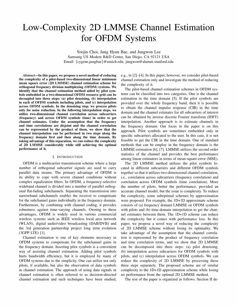
Fig. 1. An example of OFDM systems with pilot symbols embedded; grayedboxes denote pilot symbol locations.
scribes the system model. In Section III, we briefly review thepilot-based channel estimation schemes. Section IV presentsour low-complexity LMMSE channel estimation method. Sim-ulation results and conclusion can be found in Section V andSection VI, respectively.
II. SYSTEM MODEL
In OFDM systems, transmit symbols are allocated in a two-dimensional resource grid indexed by (k, l), where k and l aresubcarrier (frequency) index and OFDM symbol (time) index,respectively. By taking advantage of cyclic prefix insertion, thetransmission of one OFDM symbol over a frequency-selectivechannel in the time domain is converted into a transmissionover parallel flat-fading subchannels in the frequency domain.In order to support pilot-based channel estimation, pilot sym-bols are embedded at some subcarriers of selected OFDMsymbols in the resource grid. A set of pilot observations (closeto the channel of interest) are usually used together in channelestimation as long as complexity would allow. We group thepilots used together in channel estimation by their OFDMsymbol index. Let l1, l2, . . . , ln be the indices of the OFDMsymbols containing pilot symbols; n is the number of suchOFDM symbols. Let Xi
p, 1 ≤ i ≤ n, be the diagonal matrixconsisting of pilot symbols transmitted in OFDM symbol li.Assuming additive white Gaussian background noise, thebaseband observation of these pilot symbols at the receiverin the frequency domain is given by a column vector yipsatisfying
yip = Xiph
ip + nip,
for 1 ≤ i ≤ n, where hip is the column vector of the channelsat the pilot locations in the frequency domain; the subscribe pdenotes “pilot.” Letting pilot symbols are known deterministicand are of unit power, it can be rewritten as
zip = (Xip)
∗yip = hip + (Xip)
∗nip, (1)
where A∗ is the conjugate transpose of matrix A. Note that zipcan be thought of channel observation at the pilot locations. An
example of our system model with pilot symbols is depictedin Figure 1, where pilot symbols are embedded in four OFDMsymobls l1 = 1, l2 = 5, l3 = 8, and l4 = 14; n = 4 in thiscase. Considering the pilots in OFDM symbols l1, l2, . . . , lnall together renders
zp = hp + X∗pnp,
where
zp =
z1p...znp
, hp =
h1p...hnp
, np =
n1p...nnp
, (2)
and
Xp =
X1p 0 · · · 0
0 X2p · · ·
......
.... . . 0
0 · · · 0 Xnp
.The additive background noise np is white Gaussian withzero mean and covariance σ2I; moreover, it is assumed tobe independent to the channel vector hp. We can easily seethat X∗
pnp is statistically identical to np. In the pilot-basedchannel estimation, it is of interest to estimate any channelvalue h(k,l) at subcarrier k of OFDM symbol l for 1 ≤ k ≤ Kand 1 ≤ l ≤ L from the pilot observation yp (or the channelobservation zp at the pilot locations) by relying on the channelcorrelation.
A. Channel Correlation
In order to estimation channels from pilot signal, it is criticalto use an appropriate channel correlation model. Throughoutthe paper, we assume that the correlation of channels h(i,j)
and h(k,l) satisfy
Rh(i,j)h(k,l)= E[h(i,j)h
∗(k,l)] = rf (i− k)rt(j − l), (3)
for correlation functions across subcarriers (frequency) andacross OFDM symbols (time), rf (·) and rt(·), respectively. Itis important to see that the channel correlation is representedby the product of the frequency only dependent and timeonly dependent terms, which is the key property that weutilize in our complexity reduction algorithm of 2D LMMSEscheme. We note that this is a reasonable assumption thatwe can make under the Wide-Sense Stationary UncorrelatedScattering (WSSUS) channel model. Provided the power-delayprofile of the channel, the frequency correlation function rf (·)can be written as
rf (i− k) =
M−1∑m=0
ρme−j2π(i−k)∆fτm , (4)
where M is the number of channel taps (i.e., paths) in thetime domain, ρm and τm are the power and delay of the m-thchannel tap, respectively, and ∆f is the subcarrier spacing;note that it holds under the assumption that the channel tapsare uncorrelated. Furthermore, given a Doppler frequency, the

channel time correlation can be derived from the well-knownJakes’ model:
rt(j − l) = J0(2πTsfD(j − l)), (5)
where J0(·) is the zeroth order Bessel function of the firstkind, Ts is the OFDM symbol duration and fD is the Dopplerspread estimate. The channel correlation is then given by theproduct of (4) and (5) as in (3).
III. PILOT-BASED CHANNEL ESTIMATION
In this section, we discuss two conventional pilot-basedchannel estimation schemes for OFDM systems. Provided thechannel correlation, the best linear method is the LMMSE es-timation. In order to use pilots located in different subcarriersand different OFDM symbols together in channel estimation,we need to utilize both frequency and time correlations inLMMSE. However, there is a complexity issue in this 2DLMMSE when the number of pilots used together is notsmall. For reducing the complexity, it is employed to performLMMSE across subcarriers first and then across OFDM sym-bols. This 1D+1D method however suffers from performanceloss.
A. 2D LMMSE
Given the correlation of channels, the LMMSE estimationyields the best linear solution in terms of minimizing channelestimation MSE. For notational simplicity, let RXY be thecorrelation of any random variables or vectors X and Y , i.e.,
RXY = E[XY ∗].
Using the pilot channel observation zp in (1), the LMMSEchannel estimate h(k,l) at subcarrier k of OFDM symbol l isgiven by
h(k,l) = Rh(k,l)hp(Rhphp + σ2I)−1︸ ︷︷ ︸=W2D
(k,l)
zp. (6)
We call this scheme as 2D LMMSE since we utilize pilotsymbols distributed in two-dimensional resource grid. In anaive implementation, the 2D LMMSE filtering matrix W2D
(k,l)
is first computed and stored in memory for each of (k, l),and, then, one-shot interpolation follows for each (k, l). Inthis manner, the number of multiplications for one channelestimate is equal to the number of pilot observations used.
B. 1D+1D Approximation
In order to reduce the complexity of the 2D LMMSEscheme, we separate the 2D LMMSE filtering into twoone-dimensional processes: (a) frequency-domain LMMSE,and (b) time-domain interpolation. The LMMSE along thefrequency-domain is performed only for OFDM symbols con-taining pilot symbols, and, then, time-domain interpolationfollows using the frequency-domain LMMSE output.
Just for notational simplicity, we let
CFDi (k) = Rh(k,li)
hip, AFD
i = Rhiph
ip; (7)
note that CFDi (k) is the cross-correlation between the channel
at subcarrier k and the channels for pilots in OFDM symbol li;AFDi is the auto-correlation of the channels for pilots in OFDM
symbol li. The superscript FD implies “frequency domain.” Ineach OFDM sybmol li, 1 ≤ i ≤ n, LMMSE for estimatingchannel of subcarrier k results in
hFD(k,li)
= CFDi (k)(AFD
i + σ2I)−1︸ ︷︷ ︸=WFD
i (k)
zip. (8)
In this LMMSE step, we utilize frequency domain channel cor-relation only, i.e., CFD
i (k) and AFDi depend on the frequency
dependent correlation rf (·) only. After this frequency domainprocessing, time domain interpolation follows in order to findthe channel of subcarrier k at the OFDM symbol l of interest.
For time-domain interpolation, one can employ any kind ofinterpolation scheme, e.g., linear interpolation/extrapolation,average, extension and LMMSE. Since the other interpolationmethods are straightforward, we discuss the time domainLMMSE further in this paper. For the time domain LMMSE,we need to determine the residual noise level of the frequencydomain LMMSE output. We use the average estimation erroras the residual noise. To this end, we represent the frequency-domain estimate of the channel h(k,li) as follows:
hFD(k,li)
= h(k,li) + e(k,li),
where e(k,li) is the estimation error. From (8), the errorcovariance is given by
E[|e(k,li)|2] = 1−CFD
i (k)(AFDi + σ2I)−1CFD
i (k)∗.
For simplicity, we approximate that the errors e(k,li) for 1 ≤i ≤ n are uncorrelated and have the same variance equal totheir average value:
σ2e =
1
n
L∑i=1
E[|e(k,li)|2].
Furthermore, we assume that the errors are independent of thechannels even though there are actually dependency. Underthis approximation, applying n-tap LMMSE by using timedomain channel correlation yields time-domain interpolationoutput:
h(k,l) = CTD(l)(ATD + σ2eI)
−1︸ ︷︷ ︸=WTD(l)
hFD
(k,l1)
...hFD
(k,ln)
,where
CTD(l) = [rt(l − l1) · · · rt(l − ln)],
and
ATD =
CTD(l1)...
CTD(ln)
;
the superscript TD denotes “time domain.” Suppose that weneed to estimate channels at subcarrier k for L differentOFDM symbols. Given the LMMSE filtering matrices, the 2D

LMMSE scheme requires P ×L multiplication in total, whereP is the total number of pilots. Using the 1D+1D approximatescheme, however, the number of multiplications reduces toP + n × L; we usually have n � P (recall that n is thenumber of OFDM symbols containing pilots). The complexityreduction comes from the fact that we can reuse the frequency-domain interpolation output in the next step of time-domaininterpolation to get channels at multiple OFDM symbols.However, the reduced complexity comes with performancedegradation by losing the optimality of 2D LMMSE.
IV. LOW-COMPLEXITY 2D LMMSE
In this section, we present a novel method of reducingthe complexity of the 2D LMMSE scheme in Section III-Awithout losing its optimality. To this end, we first show that the2D LMMSE solution given in (6) can be separated into threesteps: (a) pilot processing, (b) frequency-domain processing,and (c) time-domain processing.
A. Decomposition
By definition in (2), it is straightforward that
Rh(k,l)hp= [Rh(k,l)h1
pRh(k,l)h2
p· · · Rh(k,l)hn
p].
Under the assumption that the channel correlation is repre-sented by the product of frequency dependent and time de-pendent correlations, as in (3), the cross correlation Rh(k,l)hi
p
for each i, 1 ≤ i ≤ n, satisfies (see also (7))
Rh(k,l)hip
= rt(l − li)CFDi (k).
Thus, Rh(k,l)hp can be decoupled by the product of frequencydependent and time dependent terms as follows:
Rh(k,l)hp= CTD(l)CFD(k), (9)
where
CFD(k) =
CFD
1 (k) 0 · · · 0
0 CFD2 (k) · · ·
......
.... . . 0
0 · · · 0 CFDn (k)
.Plugging (9) into (6), the 2D LMMSE solution can be rewrittenas
h(k,l) = CTD(l)CFD(k)(Rhphp + σ2I)−1zp.
One can observe that h(k,l) in the preceding equation can becomputed by the following three separate steps:
(a) Pilot denoising:
hp = (Rhphp+ σ2I)−1zp.
(b) Frequency-domain processing:
hFDk = CFD(k)hp.
(c) Time-domain processing:
h(k,l) = CTD(l)hFDk .
In the first step, we only process pilots for noise reduction.Next, we process OFDM symbols containing pilot symbolsand get intermediate output of channel estimation usingfrequency-domain correlation only. In the final step, we dotime-domain processing by using the preceding intermediateoutput of frequency-domain processing; note that only thetime-domain correlation is used in the final step.
B. Implementation
This subsection further describes the specifics of the low-complexity 2D LMMSE scheme. In the first step, we do pilotdenoising:
hp =
h1p...hnp
= (Rhphp+ σ2I)−1︸ ︷︷ ︸
=Wp
zp.
Next, frequency-domain processing follows at each of ODFMsymbols with pilots, i.e., for OFDM symbols of indicesl1, l2, . . . , ln:
hFD(k,li)
= CFDi (k)hip,
for i = 1, 2, . . . , n. Finally, time-domain processing yields achannel estimate:
h(k,l) = CTD(l)
hFD
(k,l1)
...hFD
(k,ln)
=
n∑i=1
rt(l − li)hFD(k,li)
.
The number of multiplications required in the frequency andtime domain processing in this scheme is equal to the 1D+1Dapproximation scheme. There are additional multiplications inthe pilot denoising step, which is small compared to the onesneed in interpolation when the pilots are sparsely distributed.We will discuss more the complexity in the next subsection.
C. Complexity
We compare the complexity of pilot-based channel estima-tion schemes that we presented in the previous subsections. Wefocus on the number of multiplications required for interpola-tion. The complexity of generating LMMSE filtering matricesare also important, in particular, when the size of matrix arebig, but we assume that the number of pilots used together forchannel estimation is small and the OFDM symbols containingpilots are also sparse enough so that computation of LMMSEfiltering matrices are not a dominant factor of computationalcomplexity. It is also argued that pilot symbol locations areusually repeated with the same pattern periodically in theOFDM resource grid, and the same filtering matrix can bereused for different portion of the resource grid. In such case,the complexity of interpolation becomes the major bottleneck.
Let P be the number of pilots. Recall that the number ofOFDM symbols with pilots is denoted by n. Suppose thatwe are interested in channel values of K subcarriers in LOFDM symbols. The total number of multiplication requiredfor the naive 2D LMMSE scheme is P × (K ×L− P ) sinceP multiplications are required for each data channel values of
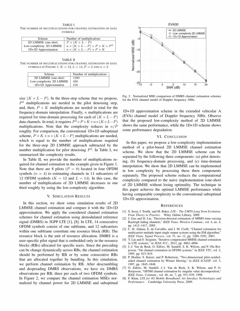
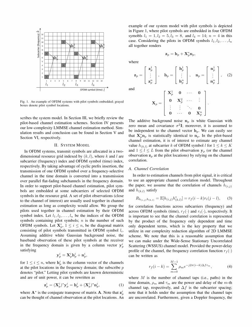
TABLE ITHE NUMBER OF MULTIPLICATIONS FOR CHANNEL ESTIMATION OF DATA
SYMBOLS
Scheme Number of multiplications2D LMMSE (one-shot) P × (K × L− P )
Low-complexity 2D LMMSE n× (K × L− P ) + P ×K + P 2
1D+1D Approximation n× (K × L− P ) + P ×K
TABLE IITHE NUMBER OF MULTIPLICATIONS FOR CHANNEL ESTIMATION OF DATA
SYMBOLS IN FIGURE 1; K = 12, L = 14, P = 2 AND n = 2
Scheme Number of multiplications2D LMMSE (one-shot) 1280
Low-complexity 2D LMMSE 4801D+1D Approximation 416
size (K × L− P ). In the three-step scheme that we propose,P 2 multiplications are needed in the pilot denoising step,and, then, P × K multiplications are needed in total for thefrequency-domain interpolation. Finally, n multiplications arerequired for time-domain processing for each of (K×L−P )data channels. In total, it requires P 2+P×K+n×(K×L−P )multiplications. Note that the complexity reduces in n/Proughly. For comparison, the conventional 1D+1D suboptimalscheme, P ×K+n×(K×L−P ) multiplications are needed,which is equal to the number of multiplications requiredfor the three-step 2D LMMSE approach subtracted by thenumber multiplication for pilot denoising P 2. In Table I, wesummarized the complexity results.
In Table II, we provide the number of multiplications re-quired for channel estimation in the example given in Figure 1.Note that there are 8 pilots (P = 8) located in four OFDMsymbols (n = 4) to estimating channels in 14 subcarriers of12 OFDM symbols (K = 12 and L = 14). In this case, thenumber of multiplications of 2D LMMSE decreases in onethird roughly by using the low-complexity algorithm.
V. SIMULATION RESULTS
In this section, we show some simulation results of 2DLMMSE channel estimation and compare it with the 1D+1Dapproximation. We apply the considered channel estimationschemes for channel estimation using demodulated referencesignal (DMRS) in 3GPP LTE [1], [8]. In LTE, 14 consecutiveOFDM symbols consist of one subframe, and 12 subcarrierswithin one subframe constitute one resource block (RB). Theresource block is the unit of resource allocation. DMRS is auser-specific pilot signal that is embedded only in the resourceblocks (RBs) allocated for specific users. Since the precodingcan be change dynamically across RBs, the channel estimationshould be performed by RB or by some consecutive RBsthat are allocated together by bundling. In this simulation,we perform channel estimation by RB. After descramblingand despreading DMRS observations, we have six DMRSobservations per RB; three per each of two OFDM symbols.In Figure 2, we compare the channel estimation MSEs nor-malized by channel power for 2D LMMSE and suboptimal
−10 −5 0 5 10 15 20−25
−20
−15
−10
−5
0
SNR (dB)
No
rma
lize
d M
SE
(d
B)
EVA30
2D LMMSE
Low−complexity 2D LMMSE
1D+1D Approxmation
Fig. 2. Normalized MSE comparison of DMRS channel estimation schemesfor the EVA channel model of Doppler frequency 30Hz.
1D+1D approximation scheme in the extended vehicular A(EVA) channel model of Doppler frequency 30Hz. Observethat the proposed low-complexity method of 2D LMMSEshows the same performance, while the 1D+1D scheme showssome performance degradation.
VI. CONCLUSION
In this paper, we propose a low-complexity implementationmethod of a pilot-based 2D LMMSE channel estimationscheme. We show that the 2D LMMSE scheme can beseparated by the following three components: (a) pilot denois-ing, (b) frequency-domain processing, and (c) time-domaininterpolation. We show that 2D LMMSE can be implementedin low complexity by processing these three componentsseparately. The proposed scheme reduces the computationalcomplexity compared to the naive implementation (one-shot)of 2D LMMSE without losing optimality. The technique inthis paper achieves the optimal LMMSE performance whilehaving comparable complexity to the conventional suboptimal1D+1D approximation.
REFERENCES
[1] S. Sesia, I. Toufik, and M. Baker, LTE – The UMTS Long Term Evolution:From Theory to Practice. Wiley Online Library, 2009.
[2] J. Gao and H. Liu, “Decision-directed estimation of MIMO time-varyingRayleigh fading channels,” IEEE Trans. Wireless Commun., vol. 4, no. 4,pp. 1412–1417, 2005.
[3] C. H. Aldana, E. de Carvalho, and J. M. Cioffi, “Channel estimation formulticarrier multiple input single output systems using the EM algorithm,”IEEE Trans. Signal Process., vol. 51, no. 12, pp. 3280–3292, 2003.
[4] Y. Liu and S. Sezginer, “Iterative compensated MMSE channel estimationin LTE systems,” in IEEE ICC,, 2012, pp. 4862–4866.
[5] J.-J. Van de Beek, O. Edfors, M. Sandell, S. K. Wilson, and P. Ola Bor-jesson, “On channel estimation in OFDM systems,” in IEEE VTC, vol. 2,1995, pp. 815–819.
[6] P. Hoeher, S. Kaiser, and P. Robertson, “Two-dimensional pilot-symbol-aided channel estimation by Wiener filtering,” in IEEE ICASSP, vol. 3,1997, pp. 1845–1848.
[7] O. Edfors, M. Sandell, J.-J. Van de Beek, S. K. Wilson, and P. O.Borjesson, “OFDM channel estimation by singular value decomposition,”IEEE Trans. Commun., vol. 46, no. 7, pp. 931–939, 1998.
[8] F. Khan, LTE for 4G Mobile Broadband: Air Interface Technologies andPerformance. Cambridge University Press, 2009.