addendum to the independent third-party final … · 4.4 piping and ductwork installation ......
TRANSCRIPT
Final Technologies Assessment
for Existing Once-Through Cooling System Report No. 25762-000-30H-G01G-00001
Bechtel Power Corporation. Report issued September 17, 2014
Addendum to the
Independent Third-Party Final Technologies Assessment for the Alternative Cooling Technologies or Modifications
to the Existing Once-Through Cooling System for Diablo Canyon Power Plant
Addressing the Installation of Saltwater Cooling Towers in the South Parking Lot

Final Technologies Assessment
for Existing Once-Through Cooling System Report No. 25762-000-30H-G01G-00001
Bechtel Power Corporation. Report issued September 17, 2014
PACIFIC GAS AND ELECTRIC COMPANY (PG&E) ADDENDUM TO THE DIABLO CANYON POWER PLANT
ONCE-THROUGH COOLING SYSTEM ALTERNATIVE OPTIONS REPORT
IMPORTANT NOTICE
Although care has been taken in preparing the information contained in this report, Bechtel Power Corporation (Bechtel) does not and cannot guarantee the accuracy, completeness, or feasibility of any information contained herein, and Bechtel provides no warranty and accepts no responsibility for the accuracy, completeness, or feasibility of any such information. In preparing the report, Bechtel may have had to rely upon assumptions (especially as to future conditions and events) that may or may not be expressed herein. Accordingly, neither Bechtel nor any person acting on its behalf assumes any liability to any party with respect to the use of, or for damages resulting from the use of, any information contained in this report for any purpose whatsoever and whether or not contemplated herein. No reliance by any party should be made based upon the accuracy, completeness, or feasibility of the information contained in this report, and any party using the information contained herein does so at its sole risk.
For the avoidance of doubt, any cost estimate or unit rates included or referred to in this report do not constitute an offer of any nature for any purpose on the part of Bechtel.
This report was prepared by Bechtel under Contract No. 4600018224 expressly for the use and benefit of Pacific Gas and Electric Company. Any party that reviews this report, by that act, acknowledges that it understands and accepts the statements, disclaimers, and limitations set out in this Important Notice.

Final Technologies Assessment
for Existing Once-Through Cooling System Report No. 25762-000-30H-G01G-00001
Bechtel Power Corporation. Report issued September 17, 2014 1
Table of Contents
1.0 Executive Summary......................................................................................................... 4
1.1 General ........................................................................................................................ 4
1.2 Addendum Results....................................................................................................... 8
2.0 Introduction ..................................................................................................................... 8
3.0 Preliminary Design Development..................................................................................... 9
3.1 Wet Mechanical (Forced) Draft Cooling Tower with Plume Abatement ........................ 9
3.2 Service Cooling Water ................................................................................................14
3.3 Cooling Tower Makeup and Blowdown .......................................................................15
3.4 Seawater Usage .........................................................................................................15
3.5 Seawater Discharge ....................................................................................................17
3.6 Salt Dispersion From Seawater ...................................................................................17
3.7 Layout Considerations ................................................................................................17
3.8 Pump/Fan Capacities and Power Requirements .........................................................18
4.0 Construction Approach ...................................................................................................24
4.1 Building Demolition and Relocation .............................................................................26
4.2 Excavation Activities ...................................................................................................28
4.3 Concrete and Steel Installation Activities ....................................................................29
4.4 Piping and Ductwork Installation .................................................................................29
4.5 Cooling Tower Erection ...............................................................................................29
4.6 500 kV Switchyard Expansion .....................................................................................29
4.7 Pumphouse.................................................................................................................30
4.8 Concrete Production ...................................................................................................30
4.9 Structural Backfill ........................................................................................................30
4.10 Parking and Busing .....................................................................................................30
4.11 Construction Workforce Populations ...........................................................................31
5.0 Schedule Development ..................................................................................................31
5.1 Summary ....................................................................................................................31
5.2 General Schedule Qualifications and Assumptions .....................................................31
Final Technologies Assessment
for Existing Once-Through Cooling System Report No. 25762-000-30H-G01G-00001
Bechtel Power Corporation. Report issued September 17, 2014 2
5.3 South Parking Lot Closed-Cycle Cooling Technologies ..............................................32
5.4 South Parking Lot Closed-Cycle Cooling Schedule Qualifications and Assumptions ...32
5.5 Key Events that Start Prior to NTP ..............................................................................35
5.6 Critical Path Activities .................................................................................................35
5.7 Outage Work ...............................................................................................................35
5.8 Schedule Risks ...........................................................................................................35
6.0 Estimate Development ...................................................................................................36
6.1 Estimate Overview ......................................................................................................36
6.2 Estimate Classification ................................................................................................36
6.3 Estimate Summary ......................................................................................................37
List of Tables
Table 1.2-1 Technology Cost and Schedule Summary
Table 1.2-2 Average Lost Power Output
Table 3.1-1 Average Lost Power Output
Table 3.4-1 Water Usage
Table 3.4-2 Seawater Balance
Table 3.5-1 Seawater Discharge
Table 3.8-1 5% Plume Cooling Tower Case
Table 3.8-2 55% Plume Cooling Tower Case
Table 5.1-1 Schedule Specifics for Each Approach
Table 6.3-1 Technology Estimate Summary
Table 6.3.1-1 Explanation of Technology Estimate Summary
Table 6.3.2-1 44-Cell Wet Mechanical (Forced) Draft Cooling Estimate Summary
Table 6.3.3-1 34-Cell Wet Mechanical (Forced) Draft Cooling Estimate Summary
Table 6.3.4-1 Bases of Estimates
Table 6.3.5-1 DCPP 44-Cell Wet Mechanical (Forced) Draft Cooling Quantity Summary
Table 6.3.6-1 DCPP 34-Cell Wet Mechanical (Forced) Draft Cooling Quantity Summary
List of Figures
Figure 1.1-1 44-Cell ClearSky Wet Mechanical Cooling Towers
Figure 1.1-2 34-Cell ClearSky Wet Mechanical Cooling Towers
Figure 3.1-1 44-Cell ClearSky Wet Mechanical Cooling Towers
Figure 3.1-2 34-Cell ClearSky Wet Mechanical Cooling Towers
Figure 3.1-3 Average Lost Output per Month (per Unit)
Figure 4.1-1 Site Development Plan

Final Technologies Assessment
for Existing Once-Through Cooling System Report No. 25762-000-30H-G01G-00001
Bechtel Power Corporation. Report issued September 17, 2014 3
Figure 5.3-1 Saltwater Mechanical (Forced) Draft Wet Cooling – 34-Cell Cooling Tower Arrangement
Figure 5.3-2 Saltwater Mechanical (Forced) Draft Wet Cooling – 44-Cell Cooling Tower Arrangement
List of Drawings
Number Title
25762-110-M6K-WL-00007 Piping and Instrument Schematic: Circulating Water System, Mechanical Draft Cooling (Wet) Seawater–44-Cell Option
25762-110-M6K-WL-00008 Piping and Instrument Schematic: Circulating Water System, Mechanical Draft Cooling (Wet) Seawater–34-Cell Option
25762-110-M5K-YA-00002 Water Balance Diagram
25762-110-M0X-YA-00007 Preliminary Mechanical Equipment List Wet Mechanical Draft (Seawater) – 44-Cell Option
25762-110-M6X-YA-00007 Preliminary Mechanical Valve List Wet Mechanical Draft (Seawater) – 44-Cell Option
25762-110-M0X-YA-00008 Preliminary Mechanical Equipment List Wet Mechanical Draft (Seawater) – 34-Cell Option
25762-110-M6X-YA-00008 Preliminary Mechanical Valve List Wet Mechanical Draft (Seawater) – 34-Cell Option
25762-110-P1K-WL-00034 Circulating Water System Cooling Tower Turbine Building 34-Cell Arrangement
25762-110-P1K-WL-00044 Circulating Water System Cooling Tower Turbine Building 44-Cell Arrangement
25762-110-P1K-WL-00054 Circulating Water System Switchyard Area Transmission Line Arrangement
25762-110-P1K-WL-00064 Circulating Water System Switchyard Area Transmission Line Arrangement

Final Technologies Assessment
for Existing Once-Through Cooling System Report No. 25762-000-30H-G01G-00001
Bechtel Power Corporation. Report issued September 17, 2014 4
1.0 Executive Summary
1.1 General
This final report addendum describes the findings of an additional study requested by the Nuclear Review Committee overseeing the Special Studies for Nuclear-Fueled Power Plants (NFPP) using Once-Through Cooling in California. The addendum supplements the second phase of an assessment of the viability of technologies noted in the Scope of Work dated November 7, 2011, prepared for the Diablo Canyon Power Plant (DCPP) by the Review Committee. This addendum specifically examines the installation of two sizes of ClearSky™ wet mechanical (forced) draft cooling towers in the south parking lot area of the DCPP site. The addendum supports the Nuclear Review Committee’s initiative to identify strategies to implement the California Policy on the Use of Coastal and Estuarine Waters for Power Plant Cooling. This strategy would comply with the California Once-Through Cooling Policy. The Phase 1 report, “Independent Third-Party Interim Technical Assessment for the Alternative Cooling Technologies to the Existing Once-Through Cooling System for Diablo Canyon Power Plant,” was issued on November 5, 2012. This addendum, in conjunction with the Phase 2 report, completes the effort to provide a comprehensive cost and schedule evaluation of the two wedge wire technologies that could be installed off shore at DCPP, an inshore fine mesh screening technology, five closed-cycle cooling technologies that could be installed north of the DCPP power block, and the two closed-cycle cooling technologies that could be installed in the parking lot area southeast of the DCPP power block.
The Nuclear Review Committee requested that this additional evaluation be completed in an effort to decrease the cost of implementing the closed-cycle cooling technology on the DCPP site. The primary cost drivers identified for implementing the closed-cycle cooling technology in the northern site location are:
The massive excavation effort required to remove the mountain.
The need to install a large desalination plant to supply fresh makeup water for the freshwater towers. The main report recommends using freshwater cooling towers because of the perceived difficulty to obtain permits for saltwater towers as well as the maintenance issues created by saltwater drift. Bechtel continues to believe that saltwater towers should not be used.
The need to install a water treatment plant onsite to treat reclaimed water from the water treatment plants at San Luis Obispo and Morro Bay to reduce the dependence on the desalination plant for tower makeup. To supply the reclaimed water, pumping stations and long pipelines from the city treatment plants to DCPP would need to be installed.
To address these cost drivers, the Nuclear Review Committee requested that Bechtel consider the following:
Placing the cooling towers on the south parking lot at DCPP to eliminate the need to excavate the mountain.
Using saltwater towers to eliminate the need for the desalination and water treatment plants and the associated reclaimed water piping.
The noted impacts of this modified approach would be:
The DCPP south parking lot does not have adequate space to install the number of tower cells required to support the design duty of the condenser. The smaller towers would result in higher circulating water temperatures to the condenser and in lower plant output.
Final Technologies Assessment
for Existing Once-Through Cooling System Report No. 25762-000-30H-G01G-00001
Bechtel Power Corporation. Report issued September 17, 2014 5
The use of saltwater towers will result in a more complicated permitting effort and the need to procure many more PM-10 emission offsets than would be necessary for the freshwater cooling towers.
Although we believe that the 10 CFR 50.59 process required to make any plant modification would not result in the need for a licensing amendment, it is likely that the U.S. Nuclear Regulatory Commission (USNRC) would be involved in reviewing this change, which may result in a detailed regulatory review process. It is assumed that any USNRC review would be conducted in parallel with the various state permit reviews.
The saltwater drift from the cooling towers would necessitate an additional maintenance effort by the plant staff to keep plant equipment clean. Note that during most of the year, the wind direction in this area is away from the power block, which would minimize this impact.
Most of the plant support infrastructure that is currently located in the south parking lot area needs to be relocated.
The construction effort necessary to complete the installation of the duct and piping from the turbine building to the pumphouse would be complicated by the need to maintain the use of the security and simulator buildings due to the space limitations between them.
This addendum only addresses the two technologies requested by the Nuclear Review Committee that could be installed in the south parking lot at DCPP. As noted above, the cost of the mountain excavation for the closed-cycle cooling options north of DCPP provided the impetus to evaluate these two additional saltwater cooling tower configurations. The Case 1 closed-cycle cooling configuration would be sized so that it would be plume abated to a point that the plume would be visible only 5% of the year. The Case 1B closed-cycle cooling configuration would be sized so that the plume would be visible 55% of the year. The plume from the cooling towers may provide operational problems that would have to be compensated for during plant operations.
The south parking lot location would require many of the plant infrastructure buildings and services to be demolished and reconstructed in other locations. These relocations have been accounted for in the preliminary designs for both Case 1 and Case 1B. The loss of the plant parking lots would also require that a large portion of the plant staff be bussed from offsite parking locations to the plant on a daily basis. Parking for plant operations and emergency response staff would be allocated onsite during and after the modifications.
Designing these two closed-cycle cooling options to be saltwater fed will create a significant permitting challenge. It has been determined that San Luis Obispo Air Pollution Control District (SLO-APCD) will follow the Mojave Desert Air Quality Management District (MDAQMD) Rule 1406 PM-10 road paving program for generating PM-10 emission offsets. Note that the SLO-APCD only enforces the PM emission offset process for PM-10 emissions. Consequently, there are no offset requirements for PM-2.5 emissions. The cost of completing the road paving effort has been included in the price estimate for both options.
The schedules for the permitting, design, procurement, installation, and testing of both options are driven by the permitting process and the concrete quantities that must be installed. The permitting process is estimated to be at least 6 months longer than the permits for the freshwater towers that would be installed at the north location, due to the saltwater emissions issue. The effort to install the ducts from the turbine building to the common pumphouse would require significantly more concrete since the space available will only allow the use of concrete duct rather than piping that can be used when locating the towers to the north.
Final Technologies Assessment
for Existing Once-Through Cooling System Report No. 25762-000-30H-G01G-00001
Bechtel Power Corporation. Report issued September 17, 2014 6
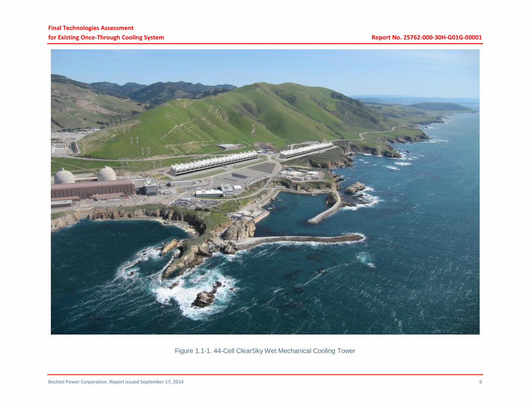
Figure 1.1-1. 44-Cell ClearSky Wet Mechanical Cooling Tower
Final Technologies Assessment
for Existing Once-Through Cooling System Report No. 25762-000-30H-G01G-00001
Bechtel Power Corporation. Report issued September 17, 2014 7
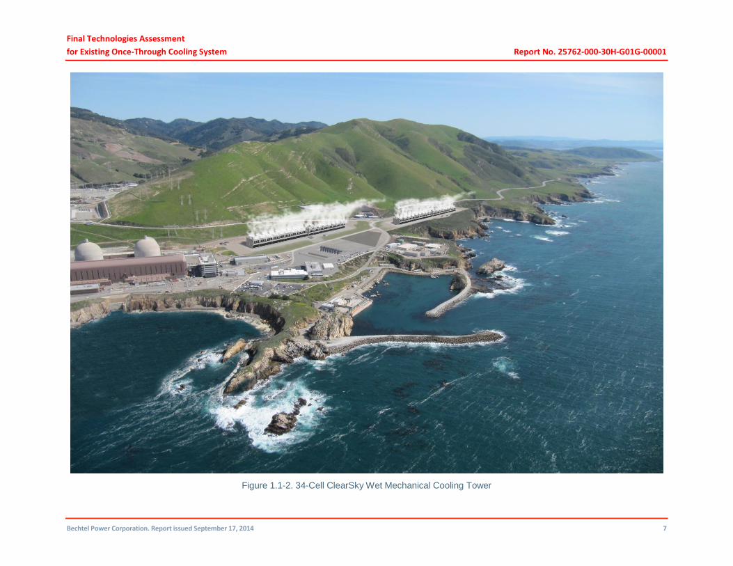
Figure 1.1-2. 34-Cell ClearSky Wet Mechanical Cooling Tower
Final Technologies Assessment
for Existing Once-Through Cooling System Report No. 25762-000-30H-G01G-00001
Bechtel Power Corporation. Report issued September 17, 2014 8
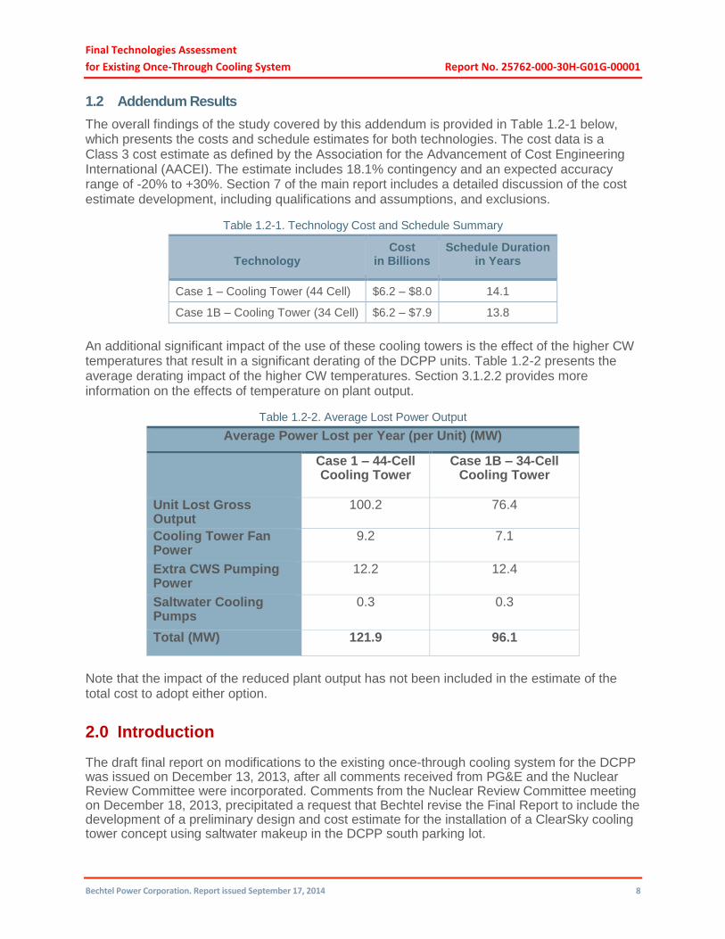
1.2 Addendum Results
The overall findings of the study covered by this addendum is provided in Table 1.2-1 below, which presents the costs and schedule estimates for both technologies. The cost data is a Class 3 cost estimate as defined by the Association for the Advancement of Cost Engineering International (AACEI). The estimate includes 18.1% contingency and an expected accuracy range of -20% to +30%. Section 7 of the main report includes a detailed discussion of the cost estimate development, including qualifications and assumptions, and exclusions.
Table 1.2-1. Technology Cost and Schedule Summary
Technology Cost
in Billions Schedule Duration
in Years
Case 1 – Cooling Tower (44 Cell) $6.2 – $8.0 14.1
Case 1B – Cooling Tower (34 Cell) $6.2 – $7.9 13.8
An additional significant impact of the use of these cooling towers is the effect of the higher CW temperatures that result in a significant derating of the DCPP units. Table 1.2-2 presents the average derating impact of the higher CW temperatures. Section 3.1.2.2 provides more information on the effects of temperature on plant output.
Table 1.2-2. Average Lost Power Output
Average Power Lost per Year (per Unit) (MW)
Case 1 – 44-Cell Cooling Tower
Case 1B – 34-Cell Cooling Tower
Unit Lost Gross Output
100.2 76.4
Cooling Tower Fan Power
9.2 7.1
Extra CWS Pumping Power
12.2 12.4
Saltwater Cooling Pumps
0.3 0.3
Total (MW) 121.9 96.1
Note that the impact of the reduced plant output has not been included in the estimate of the total cost to adopt either option.
2.0 Introduction
The draft final report on modifications to the existing once-through cooling system for the DCPP was issued on December 13, 2013, after all comments received from PG&E and the Nuclear Review Committee were incorporated. Comments from the Nuclear Review Committee meeting on December 18, 2013, precipitated a request that Bechtel revise the Final Report to include the development of a preliminary design and cost estimate for the installation of a ClearSky cooling tower concept using saltwater makeup in the DCPP south parking lot.

Final Technologies Assessment
for Existing Once-Through Cooling System Report No. 25762-000-30H-G01G-00001
Bechtel Power Corporation. Report issued September 17, 2014 9
Subsequently, the Nuclear Review Committee and Bechtel agreed to price two cooling tower configurations—one designed with a plume point generating a plume 5% of the time, and one with a plume point generating a plume 55% of the time. Both are to be designed to maintain a condenser pressure of <5 inches Hg.
3.0 Preliminary Design Development
3.1 Wet Mechanical (Forced) Draft Cooling Tower with Plume Abatement
Saturated air leaving a cooling tower comes in contact with cold, humid ambient air, which causes some of its moisture to condense. If enough condensed vapor is present, it creates a plume that has the appearance of fog or a cloud. The plume may reduce visibility and cause icing on nearby road surfaces, depending on the temperature, and is aesthetically undesirable. The plume point is the weather condition (combination of moisture content and dry bulb temperature [DBT]) at which the plume becomes visible at the cooling tower exit. Colder DBTs and increased moisture content in the atmospheric air increase the possibility of plume generation. Therefore, plume generation is more frequent during times of the year when atmospheric air is cold and humidity is high. Frequency of plume generation can be decreased by reducing the moisture content of the wet discharge air and increasing the temperature of the ambient air that mixes with the wet air.
Alternative plume abatement technologies have been developed for cooling towers, including the “condensing technology.” One established cooling tower manufacturer has named its cooling tower plume abatement technology the “ClearSky.” In this technology, heat is exchanged from discharge air in the warm wet section to ambient air through a condensing module heat exchanger inside the cooling tower, thereby condensing some moisture from the saturated wet section air of the cooling tower and, at the same time, heating the ambient air. The wet section air with reduced moisture is then combined with the warm dry air, reducing the relative humidity of the mixed discharge air. Proper proportion of air flow through the wet section and the ambient air through the condensing modules results in the plume abatement design point. The condensed vapor can be collected as freshwater for reuse in makeup or other applications.
The design conditions for the cooling towers are:
Heat duty of the cooling towers: 7.619 x 10⁹ Btu/hr/unit
Flow: 868,300 gpm per unit
Weather conditions: DBT: 77.8F WBT: 64.5F
Two plume-abated wet mechanical (forced) draft cooling tower cases are considered:
Case 1 – Mechanical (forced) draft wet cooling tower with seawater for a plume 5% of the time
Case 1B – Mechanical (forced) draft wet cooling tower with seawater for a plume 55% of the time
Both cases use saltwater as the circulating water (CW). The makeup is pumped by saltwater makeup pumps located at the existing intake structure.

Final Technologies Assessment
for Existing Once-Through Cooling System Report No. 25762-000-30H-G01G-00001
Bechtel Power Corporation. Report issued September 17, 2014 10
3.1.1 Case 1 – Plume-Abated Cooling Tower with a Plume 5% of the Time
This cooling tower is designed to have the plume visible approximately 5% of the year. The plume point is at 48F DBT, 93% RH.
For Case 1, each unit would have two cooling tower structures. Each cooling tower would have 22 cells, with a total of 44 cells per unit. Each cell would be 60 feet wide and 56 feet long. The cells would be arranged back to back, 11 cells in a row. Each cooling tower structure would be 120 feet wide and 616 feet long. Both cooling tower structures for each unit would share a common basin.
Four new volute-style CWS pumps (4 x 25%) would be provided per unit, each capable of a design circulating water system (CWS) flow of 217,075 gpm at 150 ft TDH. The pumps would be housed in a new pumphouse structure located southeast of the existing turbine building. The pumphouse would be common to both units.
Each cooling tower cell would require 270 BHP fan power (a total of 11,880 BHP for the two towers).
Piping and instrumentation (P&I) Schematic 25762-110-M6K-WL-00007 represents the CWS piping arrangement with the 44-cell plume-abated wet mechanical (forced) draft cooling towers.
General Arrangement Drawings 25762-110-P1K-WL-00044 and 25762-110-P1K-WL-00054 show tower locations, pump locations, and pipe routings.
The towers would be capable of maintaining a design cold CWS temperature of 101.5F at 64.5F inlet WBT.
A closed-cycle cooling system would require an increase in the overall design pressure of the CWS. The tube side of the main condensers would be modified to increase the tube-side pressure design from 25 psig to 50 psig. This pressure increase would account for the system losses and the increased hydrodynamic loadings resulting from the CWS modified arrangement. This higher pressure is established by the cooling tower basin elevation of 115 feet and is limited by the CWS duct design that forms part of the DCPP turbine building.
Equipment List 25762-110-M0X-YA-00007 provides additional details about the new mechanical equipment that would be furnished, and Valve List 25762-110-M6X-YA-00007 lists the new major valves that would be required. A rendering of the 44-cell ClearSky wet mechanical cooling tower is provided in Figure 3.1-1.

Final Technologies Assessment
for Existing Once-Through Cooling System Report No. 25762-000-30H-G01G-00001
Bechtel Power Corporation. Report issued September 17, 2014 11
Figure 3.1-1. 44-Cell ClearSky Wet Mechanical Cooling Tower

Final Technologies Assessment
for Existing Once-Through Cooling System Report No. 25762-000-30H-G01G-00001
Bechtel Power Corporation. Report issued September 17, 2014 12
3.1.2 Case 1B – Plume-Abated Cooling Tower with a Plume 55% of the Time
3.1.2.1 General
This cooling tower is designed to have the plume visible approximately 55% of the year. The plume point is 60F DBT, 93% RH.
Each unit would have two cooling tower structures, one with 16 cells and the other with 18 cells. Each cell would be 60 feet wide and 56 feet long. The cells would be arranged back to back, eight cells in a row for one tower structure and nine cells in a row for the second tower structure. Both towers would be 120 feet wide, and 448 feet and 504 feet long, respectively. Both cooling tower structures of each unit would share a common basin.
Four new volute-style CWS pumps (4 x 25%) would be provided per unit, each capable of a design CWS flow of 217,075 gpm at 150 ft TDH. The pumps would be housed in a new structure located southeast of the existing turbine building. The pumphouse would be common to both units.
Each cell would require 270 BHP fan power (a total of 9,180 BHP for two towers).
P&I Schematic 25762-110-M6K-WL-00008 represents the CWS piping arrangement with the 34-cell plume-abated wet mechanical (forced) draft cooling towers.
General Arrangement Drawings 25762-110-P1K-WL-00034 and 25762-110-P1K-WL-00064 show tower locations, pump locations, and pipe routings.
The towers would be capable of maintaining a design cold CWS temperature of 94F at 64.5F inlet WBT.
A closed-cycle cooling system would require an increase in the overall design pressure of the CWS. The tube side of the main condensers would be modified to increase the tube-side pressure design from 25 psig to 50 psig. This pressure increase would account for the system losses and the increased hydrodynamic loadings that result from the CWS modified arrangement. This higher pressure is established by the cooling tower basin elevation of 115 feet and is limited by the CWS duct design that forms part of the DCPP turbine building.
Equipment List 25762-110-M0X-YA-00008 provides additional details about the new mechanical equipment that would be furnished, and Valve List 25762-110-M6X-YA-00008 lists the new major valves that would be required. A rendering of the 34-cell ClearSky wet mechanical cooling tower is provided in Figure 3.1-2.
3.1.2.2 Lost Output
The cooling towers are sized to maintain a condenser pressure at <5 inches Hg or less at the design point. As noted above, the cold water temperature of the Case 1 44-cell tower reaches 101.5F and the cold water temperature of the Case 1B 34-cell tower reaches 94F. These temperatures, along with the effect of the plume abatement, form the bases of the lost power predictions noted below. The power generated by the turbine would be reduced from the existing once-through cooling system due to the increased condenser pressure. Since the condenser pressure would be limited to <5 inches Hg, it has been determined that LP turbine modifications will not be required for either of these options. However, other turbine support systems would likely require tuning and possibly modifications since they were designed to operate routinely at a lower backpressure and would be required to operate for prolonged periods at these higher backpressures. The cold water temperature produced by the cooling tower varies with the wet bulb temperature (WBT) and dry bulb temperature (DBT) of the atmosphere. Therefore, the lost output would vary with the months of the year due to the changing cold water temperature produced by the cooling tower. Figure 3.1-3 shows average lost output per month (per unit) for each of the cooling tower cases.

Final Technologies Assessment
for Existing Once-Through Cooling System Report No. 25762-000-30H-G01G-00001
Bechtel Power Corporation. Report issued September 17, 2014 13
Figure 3.1-2. 34-Cell ClearSky Wet Mechanical Cooling Tower
Final Technologies Assessment
for Existing Once-Through Cooling System Report No. 25762-000-30H-G01G-00001
Bechtel Power Corporation. Report issued September 17, 2014 14
Figure 3.1-3. Average Lost Output per Month (per Unit)
Table 3.1-1 shows the average lost power output per year (per unit) for the two options.
Table 3.1-1. Average Lost Power Output
Average Power Lost per Year (per Unit) (MW)
Case 1 – 44-Cell Cooling Tower
Case 1B – 34-Cell Cooling Tower
Unit Lost Gross Output
100.2 76.4
Cooling Tower Fan Power
9.2 7.1
Extra CWS Pumping Power
12.2 12.4
Saltwater Cooling Pumps
0.3 0.3
Total (MW) 121.9 96.1
3.2 Service Cooling Water
As a result of using cooling towers in place of the once-through CWS, the existing closed-loop cold water temperature will increase from the original 76F to 101.5F for Case 1 and to 94F for Case 1B. The existing service water heat exchangers and condensate cooler are not suitable to operate with water at this increased temperature. The most cost-effective solution would be to modify the system so that the service water heat exchangers and the condensate cooler would

Final Technologies Assessment
for Existing Once-Through Cooling System Report No. 25762-000-30H-G01G-00001
Bechtel Power Corporation. Report issued September 17, 2014 15
be cooled by a once-through system using seawater, similar to the existing arrangement. For each unit, 2 x 100% saltwater cooling pumps would be installed at the existing intake structure. Each service water pump has a capacity of 10,200 gpm at 100 ft TDH. The flow rate and pump capacity of these pumps are the same for both cooling tower options. The system discharge is directed to the downstream side of the existing discharge structure.
3.3 Cooling Tower Makeup and Blowdown
The plume-abated cooling towers typically evaporate less water than non-plume-abated wet cooling towers used for the same duty. The evaporation rates and drift of the plume-abated cooling towers for each unit considered in these options are:
Case 1 – Plume-abated cooling tower (5%)
Evaporation rate: 10,930 gpm for the two towers on each unit Design drift: 0.0005%
Case 1B – Plume-abated cooling tower (55%)
Evaporation rate: 12,630 gpm for the two towers on each unit Design drift: 0.0005%
The cooling tower cycle of concentration is designed to be 1.5 for both saltwater cooling tower designs.
Based on the evaporation rate, drift, and cycle of concentration, the total cooling tower makeup requirements for both units are:
65,700 gpm for Case 1 – 44-cell tower (5% plume)
75,900 gpm for Case 1B – 34-cell tower (55% plume)
The design for each unit includes 3 x 50% capacity vertical turbine makeup water pumps. The pumps for both units are located in the intake structure with the service cooling water pumps. The pumps move seawater from the sea to the cooling towers. Pump capacities and drive power are:
Case 1 – Plume-abated cooling tower (5%) – 16,425 gpm, 125 ft TDH, 700 BHP
Case 1B – Plume-abated cooling tower (55%) – 18,975 gpm, 125 ft TDH, 800 BHP
Based on the design cycles of concentration, the total cooling tower blowdown requirements for both units are:
43,800 gpm for Case 1 – 44 cell tower (5% plume)
50,600 gpm for Case 1B – 34 cell tower (55% plume)
The blowdown discharges back into the sea through the use of offshore diffusers (one for each unit) to effectively mix and dilute the blowdown discharge with the ambient seawater.
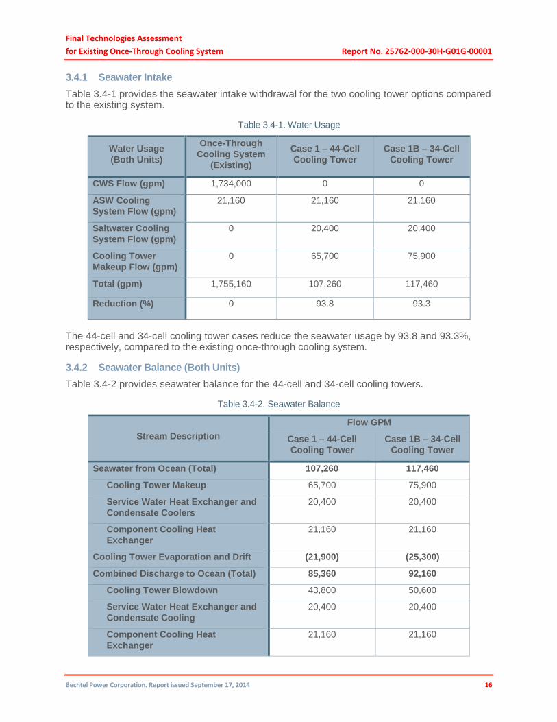
3.4 Seawater Usage
Seawater is used for the CWS makeup, to cool service water heat exchangers, and as condensate cooler and component cooling water heat exchangers.
Final Technologies Assessment
for Existing Once-Through Cooling System Report No. 25762-000-30H-G01G-00001
Bechtel Power Corporation. Report issued September 17, 2014 16
3.4.1 Seawater Intake
Table 3.4-1 provides the seawater intake withdrawal for the two cooling tower options compared to the existing system.
Table 3.4-1. Water Usage
Water Usage
(Both Units)
Once-Through
Cooling System
(Existing)
Case 1 – 44-Cell
Cooling Tower
Case 1B – 34-Cell
Cooling Tower
CWS Flow (gpm) 1,734,000 0 0
ASW Cooling
System Flow (gpm)
21,160 21,160 21,160
Saltwater Cooling
System Flow (gpm)
0 20,400 20,400
Cooling Tower
Makeup Flow (gpm)
0 65,700 75,900
Total (gpm) 1,755,160 107,260 117,460
Reduction (%) 0 93.8 93.3
The 44-cell and 34-cell cooling tower cases reduce the seawater usage by 93.8 and 93.3%, respectively, compared to the existing once-through cooling system.
3.4.2 Seawater Balance (Both Units)
Table 3.4-2 provides seawater balance for the 44-cell and 34-cell cooling towers.
Table 3.4-2. Seawater Balance
Stream Description
Flow GPM
Case 1 – 44-Cell
Cooling Tower
Case 1B – 34-Cell
Cooling Tower
Seawater from Ocean (Total) 107,260 117,460
Cooling Tower Makeup 65,700 75,900
Service Water Heat Exchanger and
Condensate Coolers
20,400 20,400
Component Cooling Heat
Exchanger
21,160 21,160
Cooling Tower Evaporation and Drift (21,900) (25,300)
Combined Discharge to Ocean (Total) 85,360 92,160
Cooling Tower Blowdown 43,800 50,600
Service Water Heat Exchanger and
Condensate Cooling
20,400 20,400
Component Cooling Heat
Exchanger
21,160 21,160

Final Technologies Assessment
for Existing Once-Through Cooling System Report No. 25762-000-30H-G01G-00001
Bechtel Power Corporation. Report issued September 17, 2014 17
For details regarding the water balance, see Drawing 25762-110-M5K-YA-00002.
3.5 Seawater Discharge
With the two cooling tower options, the seawater discharge compared to the existing system is provided in the table below.
Table 3.5-1. Seawater Discharge
Water Usage (Both Units)
Once-Through Cooling System
(Existing)
Case 1 – 44-Cell Cooling
Tower
Case 1B – 34-Cell Cooling
Tower
CWS Flow (gpm) 1,734,000 0 0
ASW Cooling System Flow (gpm)
21,160 21,160 21,160
Saltwater Cooling System Flow (gpm)
0 20,400 20,400
Cooling Tower Blowdown Flow (gpm)
0 43,800 50,600
Total (gpm) 1,755,160 85,360 92,160
Reduction (%) 0 95.1 94.7
The 44-cell and 34-cell cases reduce the seawater discharge by 95.1% and 94.7%, respectively, when compared to the existing once-through cooling system.
3.6 Salt Dispersion From Seawater
Saltwater droplets carried by the plume will drift and eventually deposit on the surrounding surfaces. The impact of this salt dispersion on nearby facilities will require the DCPP Operations and Maintenance staffs to perform an increased maintenance effort to reduce the effect of salt deposits on roadways, buildings, high voltage transmission lines, switchgear, ventilation filters, and other installations. Of significant importance will be the need to maintain the transmission and other electrical equipment clean and free of salt deposits. The wind direction is such that salt drift will be directed away from the power block during most of the year. Nevertheless, it is clear that the saltwater drift will affect the plant equipment and structures. The actual level of additional effort necessary to mitigate the effects of the saltwater drift will have to be determined based on operating experience after the saltwater towers are placed in service.
3.7 Layout Considerations
The ClearSky cooling towers will be located on the southeast side of the power block in the area currently occupied by plant infrastructure and staff parking. The Unit 1 and Unit 2 cooling towers will be located in the areas presently used as parking lots 1, 7, and 8. Parts of Diablo Ocean Drive, Shore Cliff Road, and Reservoir Road will be rerouted to provide adequate space for and access to the cooling towers. Most of the structures presently situated in the area will have to be removed. The structures and facilities that will be removed are:
I&C/telecommunications/medical facility (building 102)
Telephone terminal building (building 106)
Final Technologies Assessment
for Existing Once-Through Cooling System Report No. 25762-000-30H-G01G-00001
Bechtel Power Corporation. Report issued September 17, 2014 18
Meteorological Tower No. 1 and building (building 107)
Equipment shelter (building 112)
Warehouse B (building 113)
DCPP main warehouse (building 115)
Liquid storage warehouse (building 127)
Gas cylinder enclosure (building 130)
Access offices and training (building 163)
Used fuel storage project (building 165)
Restroom facility (building 217)
Project management offices (building 250)
Fire operations garage (building 251)
Project management offices (building 252)
Steam generator maintenance building (building 260)
Construction field engineering offices (building 261)
Facility maintenance/conference room/in-processing building (building 262)
Fire department (building 263)
Conference room/telecommunications/storage (building 264)
Concrete and soils lab (building 331)
Vehicle inspection station (VIS)
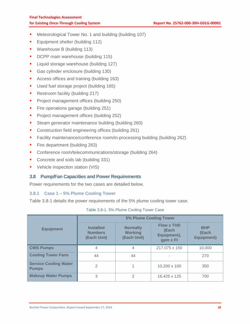
3.8 Pump/Fan Capacities and Power Requirements
Power requirements for the two cases are detailed below.
3.8.1 Case 1 – 5% Plume Cooling Tower
Table 3.8-1 details the power requirements of the 5% plume cooling tower case.
Table 3.8-1. 5% Plume Cooling Tower Case
Equipment
5% Plume Cooling Tower
Installed
Numbers
(Each Unit)
Normally
Working
(Each Unit)
Flow x THD
(Each
Equipment),
gpm x Ft
BHP
(Each
Equipment)
CWS Pumps 4 4 217,075 x 150 10,000
Cooling Tower Fans 44 44 - 270
Service Cooling Water
Pumps 2 1 10,200 x 100 350
Makeup Water Pumps 3 2 16,425 x 125 700

Final Technologies Assessment
for Existing Once-Through Cooling System Report No. 25762-000-30H-G01G-00001
Bechtel Power Corporation. Report issued September 17, 2014 19
3.8.2 Case 1B – 55% Plume Cooling Tower
Table 3.8-2 details the power requirements of the 55% plume cooling tower case.
Table 3.8-2. 55% Plume Cooling Tower Case
Equipment
55% Plume Cooling Tower
Installed
Numbers
(Each Unit)
Normally
Working
(Each Unit)
Flow x THD
(Each
Equipment),
gpm x Ft
BHP (Each
Equipment)
CWS Pumps 4 4 217,075 x 150 10,000
Cooling Tower Fans 34 34 - 270
Service Cooling Water
Pumps 2 1 10,200 x 100 350
Makeup Water Pumps 3 2 18,975 x 125 800
3.8.2.1 Control System Design
The philosophy used to develop the control systems approach for saltwater cooling towers located on the south parking lot is similar to the philosophy for the cooling tower wet technologies located to the north. Control systems and equipment were estimated in accordance with the equipment shown on the P&I schematics, the mechanical equipment lists, and the equipment described in the mechanical section of this addendum. The cooling tower control systems and equipment were estimated based on preliminary information received from cooling tower suppliers for wet technologies, except for the desalination plant reclaimed water treatment equipment, and the cost for the controls and instrumentation associated with adding a reclaimed water clarifier facility. The saltwater cooling technology is provided with makeup water pumps and saltwater pumps with associated controls and instrumentation.
As with the other wet technologies described in the main report, a distributed control system (DCS) would be provided to control and monitor equipment. DCS I/O cabinets would be located at the intake area (for new makeup and saltwater supply pumps control/monitoring), in the electrical building near the new CWS pumps (each unit), at each cooling tower electrical building/room, and in the existing main control room (to house network switches to tie in new controllers to the existing network). It is assumed that an operator workstation (OWS) human-machine interface (HMI) would be provided at each cooling tower building and that two OWSs (per unit) would be added to the main control room to control and monitor the new equipment added by this option. It is assumed that there is enough space in the existing plant areas (intake area electrical building, control room) to accommodate these new DCS I/O cabinet(s) and HMIs.
The DCS would have redundant processors and communications networks. Separate and independent DCS networks would be provided for each of the two units. Hardware for the DCS would include functionally and geographically distributed I/O cabinets, I/O modules (analog and digital), OWSs, and the connective computer hardware modules. One engineering workstation (EWS) and the software needed to develop control logic and graphic displays would be provided for each unit. The EWS would have the capability to upload and download configuration information and logic display changes into the OWSs and processors. The DCS would annunciate, indicate, time stamp, and track the status of critical parameters. Alarm history would be available on the alarm summary display screen.
Final Technologies Assessment
for Existing Once-Through Cooling System Report No. 25762-000-30H-G01G-00001
Bechtel Power Corporation. Report issued September 17, 2014 20
As part of these modifications, controls associated with the plant’s existing CWS pumps would be decommissioned and removed. New CWS pumps and valves would be installed at a new pumphouse to circulate the cooling water from the condenser outlet to the new cooling towers. Some of the existing traveling screens at the intake would remain in operation to be used for the new makeup water and saltwater supply pumps. The costs associated with removing the unused screens’ instrumentation and controls and control panels have been included in the estimate. Local instrumentation and control panels for existing CWS pumps would be decommissioned and removed. The estimate includes the demolition costs for these panels and instrumentation. The estimate also includes necessary revisions to plant drawings and documents (such as logic diagrams, instrument installation details, instrument list, and instrument data sheets).
Custom-built DCS graphics would show overview and group or detailed information to assist the operator in any type of control action required. Other DCS features are:
1. Annunciation would be predominantly in the main DCS. Major alarms and protections would be time tagged.
2. Positive indications would be provided for plant status (e.g., run/stop, open/close), and these indications would be fed back to the DCS and indicated using an appropriate graphic display.
3. Plant personnel would be able to modify and tune control loops, create or change displays, and make database changes.
The DCS network would have a redundant Ethernet data highway and Ethernet links to the MV switchgear multifunction relays and to the existing plant computer system. Redundant DCS Ethernet switches and cabling would be provided for the connection between the DCS local/remote I/O cabinets and the DCS HMIs to permit data transfer. All DCS printers and HMIs, including the historian, would be interconnected via Ethernet. All DCS communication cabling between plant buildings would be fiber optic. All DCS communication cabling within the same room would be Category V/VI copper.
The DCS would control each new MV switchgear main, tie, and load center feeder breaker. The status of each MV bus would be monitored from the DCS via data link to MV meters/relays.
3.8.2.2 Civil Design
The earlier options discussed in the main report installed cooling towers north of the plant and involved five different closed-cycle technologies, with circular cooling and the requirement for significant excavations in the mountains. The south parking lot location uses a different cooling tower configuration but still uses several similar modifications to the plant infrastructure that were outlined in the main report, which covers the north options. Two alternatives are considered: one with a 44-cell cooling tower arrangement and the other with a 34-cell arrangement.
The major civil/structural effort for this project involves (a) preliminary design of the cooling tower basins, CW pumphouse, valve pit, header box structures, and foundations for the warehouse, office, flex storage facility, and electrical buildings; (b) development of excavation quantities for placing the cooling tower basins, warehouse and parking area east of the cooling towers, and conduits and pipes; (c) ground support system for retaining the cuts in the cooling tower basin and warehouse and parking area; and (d) site work involving layout of the roads and associated site grading in the plant area. The scope of work associated with the ground support system for retaining the temporary excavations and minor vertical cuts is included in

Final Technologies Assessment
for Existing Once-Through Cooling System Report No. 25762-000-30H-G01G-00001
Bechtel Power Corporation. Report issued September 17, 2014 21
Section 4.2. Design aspects that differ from those included for the north options in the main report are described below.
The conceptual design of the cooling tower basins (one for each unit) was based on the data provided by the cooling tower supplier, with due consideration of the need for forebay areas to provide correct hydraulics flow conditions. The tower foundation consists of a rectangular basin with a minimum embedment 6 feet below the finished grade level, with the forebay region embedded deeper. Additionally, the location of the forebay differs between the Units 1 and 2 cooling towers to minimize the length of required piping. For the cooling tower and piping general arrangement, refer to General Arrangement Drawings 25762-110-P1K-WL-00044 and 25762-110-P1K-WL-00034 for the 44-cell and 34-cell tower arrangements, respectively.
Instead of providing independent pumphouses, valve pits, and header boxes for each unit, the south parking lot option locates the systems in one structure for both units. Therefore, the preliminary design estimates, including excavation quantities in the pumphouse area, incorporate the increased dimensions of these structures. The layout of the concrete conduits and piping to transport water to and from the condenser is different from that in the north options, since these subsystems turn south from the turbine building to the new cooling tower locations instead of turning north as required in the north options. Therefore, although the south parking lot option uses the same material (i.e., concrete for conduits and fiber-reinforced polymer (FRP) for the 12-foot-diameter supply and discharge piping) and conceptual design as the north options for the conduits, transition headers, and piping to accommodate restricted space and long-term durability, the concrete and excavation quantities are different.
Given that the excavation for the north options involved significant excavation in the mountains north of the plant to construct the cooling towers, the Nuclear Review Committee requested that the south parking lot option be reviewed since it offers a substantial reduction in the excavation quantities. The shape and elevation contours of the mountain terrain were traced from the topographic quadrangle maps available from the U.S. Geological Survey (USGS) official website. At the planned layout area for the new cooling towers, the existing grade would be excavated to an elevation of 115 feet to provide the space needed to build the new cooling towers, including the forebays. A clearance of 60 feet would be provided on all sides of the cooling tower basin to provide access for future inspection and maintenance. Due to restricted space and necessity for deep excavation (up to 70 feet at some locations), a ground support system involving concrete diaphragm walls (also called slurry walls) would be used to retain the earth and rock. The slurry wall ground support system would also be used to retain the rock in the warehouse and parking area, which would involve deep excavation up to 60 feet, especially on the east side of this area.
As a part of this effort, significant existing plant infrastructure would be removed and/or replaced with some modifications. Existing plant buildings 102, 106, 107, 112, 113, 115, 127, 130, 163, 165, 217, 250, 251, 252, 260–264, and 331, and the vehicle inspection station (VIS) would need to be demolished to provide space for the new cooling towers, pumphouse, CWS conduits, and pipes. Additionally, existing building 163 would be demolished and rebuilt at the same location with an additional floor to accommodate plant staff. A new two-story, 100-foot-by-200-foot office building would also be installed to house dispatched plant staff. New saltwater makeup and cooling pumps would be installed in the existing intake structure to replace the existing pumps.
Since the new cooling towers are located close to the existing plant infrastructure, the proposed plan requires modifications to the existing roads to enable permanent and temporary access to plant utilities and to facilitate the site grading. New roads are required northeast of the Unit 1 cooling tower and west of the Unit 2 cooling tower. The same layout and road lengths are planned for both the 44-cell and 34-cell case since the cooling towers are laid out with reference to the road that runs between them. Consistent with the existing road layout at the site, the new

Final Technologies Assessment
for Existing Once-Through Cooling System Report No. 25762-000-30H-G01G-00001
Bechtel Power Corporation. Report issued September 17, 2014 22
roads are planned to be 24 feet wide (General Arrangement Drawings 25762-110-P1K-WL-00044 and 25762-110-P1K-WL-00034).
The differences in the quantities for both the 44-cell and 34-cell cooling tower cases are largely attributable to the different sizes of cooling towers. There is also a small difference in the length of piping (and thus the excavation estimates), but most of the other quantities are the same for the two options.
3.8.2.3 Electrical System Design
The electrical design for the new 44-cell and 34-cell south parking lot option is different from the designs for the cooling towers located north of DCPP in the following ways:
1. In the electrical design for the south parking lot cases, there will only be two stepdown transformers, one per unit (120/60/60 MVA each), instead of four as in the designs for the north location. There will be provision for fast-bus transfer between the two units fed by the two transformers, i.e., in case of fault in one of the unit’s transformers (or switchgear), the other transformer will be capable of feeding the electrical load of both the units (and vice versa).
2. Based on the above, the quantity of MV (12 kV) switchgear will reduced to two per unit instead of four in the design used for the cooling towers located north of DCPP. Each of the two MV switchgear per unit would feed two 10,000 HP rated CW pumps located in the pumphouse. The cooling tower makeup pumps would be fed from the12 kV switchgear. The saltwater cooling pumps at the intake side would be fed from the existing 4.16 kV switchgear at DCPP (in the same way as in the design for the towers located north of DCPP).
3. With 4 MVA load center transformers (similar to the design for the towers located north of DCPP), voltage is stepped down from 12 kV to 480 V at the load centers that feed the cooling tower fans and other miscellaneous loads. The total number of low voltage (480 V) load centers for both plant units is 10 for the 44-cell case and 8 for the 34-cell case. In the existing design, 480 V load centers of the same rating were used, but the number of load centers was based on the technology, i.e., the number of load centers was different for the wet mechanical and hybrid technologies.
The physical design cable routing, electrical building etc., will be similar to the design for the towers located north of DCPP, with modified quantities.
3.8.2.4 Connection to Switchyard
The following are the differences between the design of the towers located north of DCPP and the new design for the south parking lot options for the connection of the electrical system to the 500 kV switchyard:
1. The design for the north location required rerouting of the existing 230 kV lines so that the new 500 kV lines could be routed to feed the electrical system. The south parking lot option design will not require any rerouting of the 230 kV lines, thereby eliminating all associated cost.
2. There will be just one 500 kV bay in the new south parking lot option design instead of the two 500 kV bays used in the north location design. The single bay would have two 500 kV circuits compared to four 500 kV circuits on two 500 kV bays in the north location design.
Final Technologies Assessment
for Existing Once-Through Cooling System Report No. 25762-000-30H-G01G-00001
Bechtel Power Corporation. Report issued September 17, 2014 23
3. To feed the two transformers from the switchyard, a few extra 500 kV towers would be used to relocate the current 500 kV circuits to the new bay, moving the 500 kV circuits to avoid crossing. The cost has been estimated accordingly.
3.8.2.5 Saltwater Cooling Tower Permitting
The initial Phase 1 permitting assessment focused on identifying the applicable (required) permits and approvals for constructing and operating the various closed-cycle cooling technology options and recommended that all saltwater cooling tower options be screened from further consideration in later study phases. This recommendation was based primarily on the finding that the SLO-APCD had insufficient PM-10 emission offsets to compensate for the drift-related significant particulate emissions from these saltwater tower options. Consequently, the follow-on initial Phase 2 permitting assessment of wet cooling tower systems was limited to systems that used freshwater sources (e.g., desalinization systems and/or offsite treated sanitary effluent [reclaimed water]). However, subsequent comments regarding the Phase 2 study offered evidence that there were new ways to secure the necessary PM-10 emission offsets to make the saltwater towers potentially viable from a permitting point of view. Consequently, the mechanical saltwater cooling tower technology was specifically selected for further consideration on the new location encompassing the existing parking lot areas southeast of the DCPP power block.
The list of potentially applicable permits and approvals at the Federal, California, County, and municipal levels (with the exception of the reclaimed water pipeline-related approvals) for the mechanical saltwater cooling tower system is similar to that prepared for the wet (freshwater) cooling tower systems (see Table CC-2 in the main report); however, the shift to a saltwater source does pose some schedule and cost considerations. The California Environmental Quality Act (CEQA) review remains the critical path (longest) permitting process. The CEQA lead agency may still be a shared responsibility among a number of key regulatory departments (e.g., San Luis Obispo County, CCC). The requisite USACE Section 404 permit, CCC Coastal Development Permit, CSLC Lease, SLO-APCD air permit, and NPDES permit modification will still be applicable and likely demand potentially lengthy review processes, but they will all be essentially bounded by the critical path CEQA/Environmental Impact Report (EIR) review process.
The CEQA process described for the wet tower systems will likely lengthen somewhat in response to the addition of saltwater specific impacts (salt deposition and the requisite need for significant PM-10 emission offsets). As with the other closed-cycle cooling systems under consideration, the saltwater mechanical cooling tower system will demand preparation of an EIR, which will likely take at least a year. The follow-on regulatory review process, (following submission of the draft EIR) originally forecast as a 12-month period, will likely be extended by at least 6 months.
This 18-month CEQA review process will be further extended by conservatively adding an additional 12 months to cover “unreasonable delays” ostensibly associated with the applicant’s difficulty in supplying requested information. This 3.5-year CEQA process (inclusive of application and EIR development) does not reflect the impact of permit appeals or litigation. In recognition that such complications may occur, the project execution schedules (see Figures 3.5-1 and 3.5-2) for this cooling system option adds a nominal 12-month appeal period that follows the CEQA final decision. The other permitting processes are assumed to proceed in parallel with the critical path 4.5-year CEQA review process. This duration still does not reflect the impact of any subsequent litigation.
The permitting costs for the saltwater mechanical (forced) draft cooling tower system will be somewhat different that the freshwater option costs ($4.3 million) described in Table CC-2 of the

Final Technologies Assessment
for Existing Once-Through Cooling System Report No. 25762-000-30H-G01G-00001
Bechtel Power Corporation. Report issued September 17, 2014 24
main report, since this total includes costs for offsite reclaimed water pipelines ($1.7 million) and PM-10 emission offset costs ($480,000) will not apply to the saltwater tower system. Use of the locally abundant saltwater will preclude the need for reclaimed water pipelines and the associated county and municipal level permit process and related costs. The emission offsets for the significant particulate emissions from the saltwater drift droplets will not be satisfied by purchasing existing PM-10 (particulates that are 10 microns or less in diameter) offsets, but rather through an alternative road paving process. In recent years, the MDAQMD, in cooperation with US Environmental Protection Agency (USEPA) Region IX, successfully championed a program in which applicants for a major source air permit (i.e., Prevention of Significant Deterioration Permit issued by USEPA Region IX) that required additional PM-10 emission offsets, generated these offsets by paving local unimproved roads. Given this success, representatives of the SLO-APCD have indicated that a similar process could prove successful in their district. The calculation processes for estimating the cooling tower drift-related PM-10 emissions and the particulate emission reductions associated with paving dirt or gravel roads have clear regulatory precedence in California (and the regional USEPA) for PM-10 emission offsets in amounts comparable with those that could potentially be needed at DCPP. The emission offset process is not an integral part of the best available control technology (BACT) determination. BACT determinations for cooling towers focus on the drift rate, expressed in terms of percentage of the circulating water flow. The cooling towers envisioned for DCPP boast a state-of-the-art drift rate of 0.0005%, which is currently widely accepted as BACT for cooling towers.
The cooling tower drift PM-10 emissions can be conservatively assumed to include all drift-related particulate matter regardless of size or only the PM-10 portion derived from a refined assessment process, which characterizes the portion of total particulate matter emission that is 10 microns or less in diameter. While both conservative and refined estimates were made, the local SLO-APCD has indicated a preference for the conservative methodology, i.e., all DCPP cooling tower drift emissions (some 900 tons annually) were assumed to be PM-10.
Consequently, the DCPP cooling tower drift emissions are the total PM-10 emissions that need to be offset via the road paving program. While this program avoids the direct purchase costs for existing PM-10 emission credits, there are considerable associated road paving costs. These costs (assuming a nominal $1,000,000 per mile of newly paved single-lane road) will vary, depending on the conservatism of the PM-10 facility emission rate, the nature of the subject roads, the actual local paving costs and the nature of existing road traffic on these subject roads. Based on estimates of road paving needs using the established calculation process, the conservative cooling tower drift PM-10 emission rate (900 tons/year), and the 50 vehicle/day travel rate, an expenditure of $84 million in required road development costs (84 miles of paved road) could be required. These emission offset costs, together with the other permitting costs, could raise the overall permitting costs to over $86 million. This estimate is not inclusive of potential permit/approval litigation costs and related schedule extension overruns or NRC licensing costs, so the estimate likely represents a reasonable lower boundary of the expected permitting costs.
The PM-10 portion of these cost estimates are subject to change, depending on the initial subject road conditions (dirt or gravel) and the typical daily vehicle traffic on those subject roads. It is likely this emission offset process will require that a site-specific traffic study to be conducted to confirm the vehicle miles traveled along the roads selected for paving.
4.0 Construction Approach
The construction approach for the saltwater closed-cooling option is similar to that for the other options in that the cooling tower grade elevation is set at elevation 115 feet. Locating the towers
Final Technologies Assessment
for Existing Once-Through Cooling System Report No. 25762-000-30H-G01G-00001
Bechtel Power Corporation. Report issued September 17, 2014 25
south of the plant would reduce the amount of excavation needed considerably, but significantly affect the plant support infrastructure, requiring facility space and parking to be eliminated. New facilities would need to be constructed, and a significant busing of personnel would temporarily be required. A new plant access road through the construction area would be necessary, and access to the independent spent fuel storage installation (ISFSI) (within 30 days) would have to be maintained during the construction period. The 12-foot-diameter CWS pipe routing from the cooling towers to the new pumphouse is similar for each option; however, less pipe is required for this option, and more concrete duct is needed since the available space for installing the piping near the power block is very limited. The construction of a single pumphouse for both units would be different than that for the other options, which have a smaller pumphouse for each unit. The demolition of the existing building, excavation, interference removal, and demolition of the current CWS ducting west of the turbine buildings is similar for all options; however, it is much more extensive for this option. The rebuilding of the condensers is the same for each option.
The sequence of the construction activities and installations for this closed-cycle cooling option is shown on the Level 2 schedule in Section 5.
The major construction work components of the saltwater closed-cycle cooling technology include:
Subsurface investigation for the new cooling towers and new structure footprints
Construction of a new access road to the plant, around the new cooling system footprint
Construction of a new main warehouse, main office building, flex storage building, and access processing building, and subsequent relocation of personnel and material
Demolition of 24 existing facility buildings, relocation of the south protected area fencing, and removal of parking area asphalt
Excavation and installation of retaining walls and ground support structures
Demolition and relocation of underground interferences south of the plant, installation of new sanitary, storm drain management, water, electrical, and fire protection systems
Construction of cooling tower basins and erection of the cooling towers
Construction of a new CW pumphouse with eight volute pumps
Construction of three new electrical buildings with duct bank, switchgear, and powering of the cooling towers and pumphouse
Expansion of the 500 kV switchyard and installation of additional breakers
Installation of a 500 kV transmission line from the switchyard to the new cooling tower transformers
Installation of new transformers near the cooling towers
Powering the mechanical draft fans in the cooling towers
Installation of CWS piping and valves from the cooling towers to the new pumphouse
Excavation and demolition of existing CWS duct west of the turbine building within the footprint of the new concrete ducts, while supporting the four existing ASW lines
Construction of the new CWS concrete duct from the turbine building to the new pumphouse and sealing off the existing CWS intake and discharge ducts

Final Technologies Assessment
for Existing Once-Through Cooling System Report No. 25762-000-30H-G01G-00001
Bechtel Power Corporation. Report issued September 17, 2014 26
Installation of four new saltwater cooling system pumps and underground piping from the intake structure to the plant service water cooling heat exchangers and condensate coolers
Installation of six cooling tower makeup pumps at the intake structure and underground piping and valves from the intake structure to the cooling tower basins
Decommissioning of existing CWS intake pumps and abandonment of the power feed from the plant
Demolition of the Units 1 and 2 low pressure condenser interiors and rebuilding with new higher pressure tube sheets and tubing
4.1 Building Demolition and Relocation
To accommodate the saltwater cooling system footprint, the Table 4.1-1 indicates the buildings located within the excavation area that would be demolished, along with their footprint. This represents a total footprint area of 212,728 sq ft and a total volume of 3,318,224 cubic feet. The southern protected area fencing near the main warehouse would also be required to be moved north of the warehouse. Figure 4.1-1 shows the existing site buildings that must be removed by the owner (PG&E) or construction to accommodate the installation of the cooling towers on the south parking lot area.
Table 4.1-1. Building Demolition
Building Excavation Area (sq ft)
102 16,200
106 576
107 720
112 576
113 29,280
115 93,000
127 6,000
130 1,200
160 7,126
163 11,040
165 4,340
201 14,688
202 4,608
217 864
220 1,612
248 1,612
250 2,688
251 3,420
252 2,688
260 2,480
261 2,480
262 2,480
263 1,612
264 1,716
331 2,000
VIS 1,340

Final Technologies Assessment
for Existing Once-Through Cooling System Report No. 25762-000-30H-G01G-00001
Bechtel Power Corporation. Report issued September 17, 2014 27
Figure 4.1-1. Development Plan
Final Technologies Assessment
for Existing Once-Through Cooling System Report No. 25762-000-30H-G01G-00001
Bechtel Power Corporation. Report issued September 17, 2014 28
The cost to install a new reduced-footprint warehouse east of the proposed Unit 2 cooling tower cells, a two-story administration office building in the current footprint of existing building 165 and former building 160, the flex equipment storage building east of the Unit 1 cooling tower cells, and a two-story replacement for building 163 has been included in the estimate. Additionally an allowance for some remote offsite storage (40,000 sq ft or approximately 40% of the existing onsite warehouse space) and cost for some personnel relocated to offsite office space (20,000 sq ft to accommodate approximately 120 current plant staff) have been included.
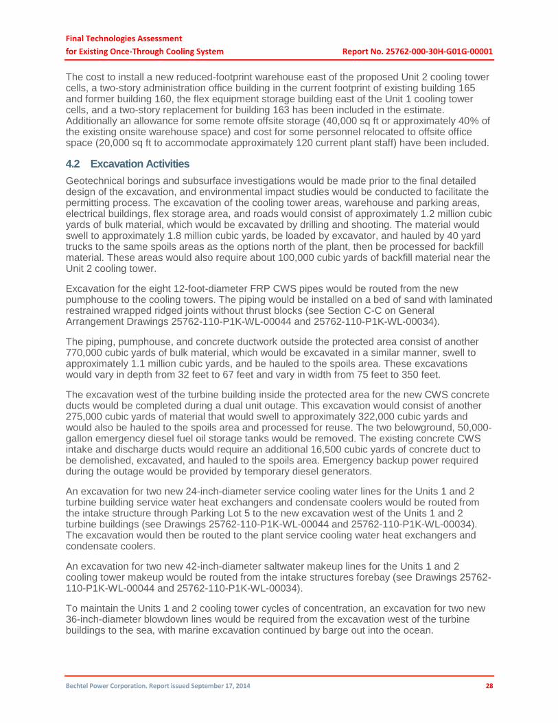
4.2 Excavation Activities
Geotechnical borings and subsurface investigations would be made prior to the final detailed design of the excavation, and environmental impact studies would be conducted to facilitate the permitting process. The excavation of the cooling tower areas, warehouse and parking areas, electrical buildings, flex storage area, and roads would consist of approximately 1.2 million cubic yards of bulk material, which would be excavated by drilling and shooting. The material would swell to approximately 1.8 million cubic yards, be loaded by excavator, and hauled by 40 yard trucks to the same spoils areas as the options north of the plant, then be processed for backfill material. These areas would also require about 100,000 cubic yards of backfill material near the Unit 2 cooling tower.
Excavation for the eight 12-foot-diameter FRP CWS pipes would be routed from the new pumphouse to the cooling towers. The piping would be installed on a bed of sand with laminated restrained wrapped ridged joints without thrust blocks (see Section C-C on General Arrangement Drawings 25762-110-P1K-WL-00044 and 25762-110-P1K-WL-00034).
The piping, pumphouse, and concrete ductwork outside the protected area consist of another 770,000 cubic yards of bulk material, which would be excavated in a similar manner, swell to approximately 1.1 million cubic yards, and be hauled to the spoils area. These excavations would vary in depth from 32 feet to 67 feet and vary in width from 75 feet to 350 feet.
The excavation west of the turbine building inside the protected area for the new CWS concrete ducts would be completed during a dual unit outage. This excavation would consist of another 275,000 cubic yards of material that would swell to approximately 322,000 cubic yards and would also be hauled to the spoils area and processed for reuse. The two belowground, 50,000-gallon emergency diesel fuel oil storage tanks would be removed. The existing concrete CWS intake and discharge ducts would require an additional 16,500 cubic yards of concrete duct to be demolished, excavated, and hauled to the spoils area. Emergency backup power required during the outage would be provided by temporary diesel generators.
An excavation for two new 24-inch-diameter service cooling water lines for the Units 1 and 2 turbine building service water heat exchangers and condensate coolers would be routed from the intake structure through Parking Lot 5 to the new excavation west of the Units 1 and 2 turbine buildings (see Drawings 25762-110-P1K-WL-00044 and 25762-110-P1K-WL-00034). The excavation would then be routed to the plant service cooling water heat exchangers and condensate coolers.
An excavation for two new 42-inch-diameter saltwater makeup lines for the Units 1 and 2 cooling tower makeup would be routed from the intake structures forebay (see Drawings 25762-110-P1K-WL-00044 and 25762-110-P1K-WL-00034).
To maintain the Units 1 and 2 cooling tower cycles of concentration, an excavation for two new 36-inch-diameter blowdown lines would be required from the excavation west of the turbine buildings to the sea, with marine excavation continued by barge out into the ocean.

Final Technologies Assessment
for Existing Once-Through Cooling System Report No. 25762-000-30H-G01G-00001
Bechtel Power Corporation. Report issued September 17, 2014 29
As the installation of in-ground items completes, the processed excavation material would be hauled from the spoils area back to the plant and used as backfill material.
4.3 Concrete and Steel Installation Activities
As the excavations are completed, the concrete placements would begin for the new structures, cooling tower forebays and basins, pumphouse, building and equipment foundations, and concrete ductwork. For the 44-cell tower arrangement, approximately 170,000 cubic yards of concrete would require 1.3 million sq ft of formwork and 35,000 tons of reinforcing steel, 200 tons of embedded items, and 658 tons of structural and miscellaneous steel. Of the 170,000 cubic yards of concrete to be placed, 120,000 cubic yards can be placed during non-outage periods, while 52,000 cubic yards of concrete ductwork west of the turbine buildings inside the protected area would be placed during a dual unit outage. The 34-cell tower arrangement has slightly less concrete at 168,000 yards, but the same amount would need to be installed during the dual unit outage.
4.4 Piping and Ductwork Installation
As the earthwork excavations are opened up, the piping and ductwork would be installed. For this option, 2,200 feet of 9-foot-diameter and 10-foot-diameter pipe, and 9,000 feet of 12-foot-diameter FRP CW piping would be buried (about half the amount required for the towers that would be installed to the north). However, the amount of the pour-in-place reinforced concrete ductwork necessary to avoid demolition of the security, training, and maintenance shop buildings is much greater. Other large-diameter piping to be installed in the excavations would consist of about 4,000 feet of 42-inch-diameter makeup water piping, 4,500 feet of 36-inch-diameter blowdown piping, 4,000 feet of 24- to 26-inch-diameter SW cooling piping, and 500 feet of 12-inch-diameter piping. The poured-in-place reinforced concrete ductwork consists of 112,000 cubic yards of concrete, of which 60,000 cubic yards outside the protected area can be placed during non-outage periods and 52,000 cubic yards inside the protected area can be placed during the dual unit outage.
4.5 Cooling Tower Erection
The saltwater wet mechanical (forced) draft towers would be erected inside the pour-in-place, reinforced concrete basin structures constructed with 9-foot walls on mass concrete foundations, with a 35-foot-deep forebay connecting to the 144-inch CW pipes. Substructure forebay foundations and walls are typically excavated, formed, and placed, followed by the basin bottom in 50-foot sections with vertical and horizontal water stops at the construction joints and 9-foot walls via concrete pumps. Once the civil construction is complete, the mechanical/piping equipment would be installed, followed by the electrical commodities to power the forced draft fans.
Cell arrangements for mechanical (forced) draft cooling towers are relatively low-profile towers and arrive onsite in modular sections. The cell array is essentially bolted together, anchored to the foundation, and connected to the 12-foot-diameter CWS. The return piping is connected to the forebay of the basin. The electrical commodities are then installed and terminated to power the forced draft fans.
4.6 500 kV Switchyard Expansion
To power the closed-cooling options, the existing 500 kV switchyard would need to be expanded, which would entail installation of three new additional breakers. The area west of the existing 500 kV switchyard would be backfilled and graded to the same elevation as the existing switchyard and one bay for the new breakers would be installed. To avoid crossing the existing 500 kV lines, Unit 1 lines would be connected to the new switchyard area (Drawings 25762-110-

Final Technologies Assessment
for Existing Once-Through Cooling System Report No. 25762-000-30H-G01G-00001
Bechtel Power Corporation. Report issued September 17, 2014 30
P1K-WL-00054 and 25762-110-P1K-WL-00064), Unit 2 lines would be connected to the current Unit 1 connection, and the current Unit 2 feed location would be interconnected to the new transformers via transmission lines and towers over the mountain to feed the new transformers near the cooling towers.
4.7 Pumphouse
The pumphouse for the closed-cooling option would consist of a 30,000 cubic yard concrete structure with eight 10,000 HP volute CWS pumps with 108-inch butterfly valves, concrete intake and discharge header boxes, and a concrete valve pit with eight 108-inch isolation butterfly valves. The pumphouse would have an electrical building for switchgear and underground duct banks for power and control electrical installations. Construction of the pumphouse and appurtenances would require excavation, installation of reinforced concrete structures with foundations, walls and slabs with embedded items, and subsequent backfilling operations. Following the civil work, the installation of mechanical equipment and piping and electrical equipment, conduit, tray, wire, and electrical terminations would follow.
4.8 Concrete Production
The closed-cycle cooling technology calls for large quantities of concrete for the construction of the cooling towers, pumphouse, electrical duct bank, and CW duct. To ease traffic congestion and to provide a quality and least-cost approach to concrete supply, concrete batch plant(s) would be erected onsite and the cement, aggregate, and admixtures would be shipped to the site. Onsite concrete mixer trucks would deliver the concrete from the batch plant to the points of placement.
4.9 Structural Backfill
To accommodate the structural backfill requirements, a crushing/screening/blending plant would be located at the excavation spoils area to manufacture the necessary backfill material from the excavated spoils.
4.10 Parking and Busing
The estimate considers maintenance of onsite parking for 350 personnel to accommodate plant operations and emergency response staff during the construction period. The balance of approximately 800 current plant employees/contractors during non-outage periods, and approximately 1,800 personnel during refueling outage periods would be bused to and from the plant each day from a remote parking facility in the San Luis Obispo area. The buses would make two round trips per day during non-outage periods and three round trips per day during outage periods. Additionally, a single shuttle bus would run 24 hours a day, 7 days a week, leaving the plant site and San Luis Obispo every other hour.
To accommodate the operations and construction workforce parking requirements and ease traffic on the plant access road, the operations and construction workforce would park in a remote parking area offsite in San Luis Obispo and be bused to the plant work locations onsite. The busing service would be free to the plant operations staff/contractor personnel without being paid to ride. The cost of construction and operation of a remote parking facility has been included in the owner (PG&E) costs estimate. These costs include purchase of 12 acres; necessary improvements to the remote parking area such as grading, stormwater controls, paving, curbing, lighting, and restroom facilities; and maintenance of the parking area (trash management, lighting/power, and temporary security management). The cost of the busing service for construction personnel assumes that they are paid to ride and is included in the EPC construction cost estimate.

Final Technologies Assessment
for Existing Once-Through Cooling System Report No. 25762-000-30H-G01G-00001
Bechtel Power Corporation. Report issued September 17, 2014 31
4.11 Construction Workforce Populations
To accommodate the saltwater cooling tower option, the construction workforce population onsite would vary during the course of installation activities. The approximate construction workforce population required to accomplish the schedule durations would be approximately 585 personnel (per shift) working two shifts, 5 days per week, 10 hours per day during the non-outage period. During the dual-unit outage period, the work schedule would be adjusted to 24 hours per day, 7 days per week to minimize the outage duration and would require approximately the same number of personnel per shift performing the outage scope of work.
5.0 Schedule Development
5.1 Summary
The two south parking lot arrangements are projected to be completed approximately 8.6 to 8.8 years after the 5.5-year permit approval process is completed. While the outage period is the same for both arrangements, the 44-cell arrangement is expected to take 3 months longer than the 34-cell arrangement due to additional concrete work for ground support, basin and cooling tower foundations.
Table 5.1-1. Schedule Specifics for Each Approach
Milestone Description (years from NTP)
South Wet Mechanical
(Forced) Draft Cooling 34 Cell Tower
South Wet Mechanical
(Forced) Draft Cooling 44 Cell Tower
CEQA Review Process –5.5 –5.5
Notice to Proceed 0 0
Pre-Outage Construction Complete
6.25 6.5
Outage Complete and T/O to Operations
8.3 8.6
Total Duration (approximate)
13.8 14.1
Each of the cases was evaluated and a schedule was developed to cover the design, construction, and commissioning of that case. The philosophy underpinning the schedule development process was to 1) minimize PG&E’s outlay of funds until such time as the permitting process was nearing completion, 2) determine the most efficient design and construction sequence, and 3) design and construct the project so that the time in which one or both of the units are offline is kept to an absolute minimum. The process used to develop the schedule for each technology is discussed in detail below.
5.2 General Schedule Qualifications and Assumptions
General schedule qualifications and assumptions are as follows:
Permitting durations are based on recent California related power plant permitting experience and the individual regulatory agency guidance on review periods. These durations do not include the impacts of litigation or potentially applicable nuclear licensing.
Considering related permits and their respective processes, the CEQA permit will require the most time during the permitting process.

Final Technologies Assessment
for Existing Once-Through Cooling System Report No. 25762-000-30H-G01G-00001
Bechtel Power Corporation. Report issued September 17, 2014 32
It is assumed that any NRC reviews that may be required for these changes will be completed in parallel with the state permitting process.
5.3 South Parking Lot Closed-Cycle Cooling Technologies
The closed-cycle cooling technology solution for the south parking lot consists of two approaches, and a separate schedule has been developed for each approach. The project team initially collaborated to identify individual tasks/milestones and the appropriate sequence in which the work needed to proceed. Engineering, permitting, construction, and startup task durations were evaluated based on their complexity, physical location, effect on station operation, and past performance on previous Bechtel projects. Procurement, vendor, and subcontract durations were confirmed with potential suppliers or supported by past performance metrics from Bechtel projects. The project team then worked to optimize each schedule, focusing on minimizing outage duration, permitting risk, and impacts on plant operations.
Each closed-cycle cooling technology schedule has the same basic structure and duration. The summary-level project implementation schedule developed for each of the two south parking lot closed-cycle cooling options is provided in Figures 5.3-1 and 5.3-2. The two south parking lot technologies are projected to be completed approximately 8.6 to 8.8 years after the permit approval process is completed. Case 1 (44-cell tower arrangement) is expected to take 3 months longer than Case 1B (34-cell tower arrangement). Each of these schedules includes an initial 5.5-year period prior to NTP that will be dedicated solely to submitting and acquiring permit approvals. It is important to note that the construction activities are scheduled to focus on the area outside the current plant protected area separate from the construction activities inside the protected area for both of the options on the south parking lot. This approach was used to maximize productivity and minimize impact on the operating plants. It is the same approach taken for the options on the north plant site location.
5.4 South Parking Lot Closed-Cycle Cooling Schedule Qualifications and Assumptions
Closed-cycle cooling schedule qualifications and assumptions for the south parking lot are as follows:
The 500 kV line and switchyard will be modified to provide power to the south parking lot area.
Construction of new office and warehouse facilities to support the relocation of existing personnel will be required prior to constructing the saltwater towers.
A task to improve approximately 84 miles of unimproved roads by paving them to acquire the necessary PM-10 credits is included but does not affect the overall duration of these options.
A concrete batch plant and backfill crusher plant will be required to be erected immediately following NTP.
Procurement/construction work will not begin until after permit approval is received. The engineering specification bid and evaluation process would be completed, but it is assumed that procurement and construction activities would not be performed until the permitting process is completed.
For all of the closed-cycle cooling technologies, the construction approach is to complete as much of the scope prior to the plant outages as possible. This will minimize the outage time for the remaining work related to CW pipe removal and installation tie-ins and hookups.
Some schedule improvement may be realized if PG&E agrees to limited equipment award, especially to support design activities. It would be PG&E’s decision to assume some risk in this area based on confidence gained during the permitting process and may be deemed reasonable and acceptable, but this was not considered in the development of the schedules.
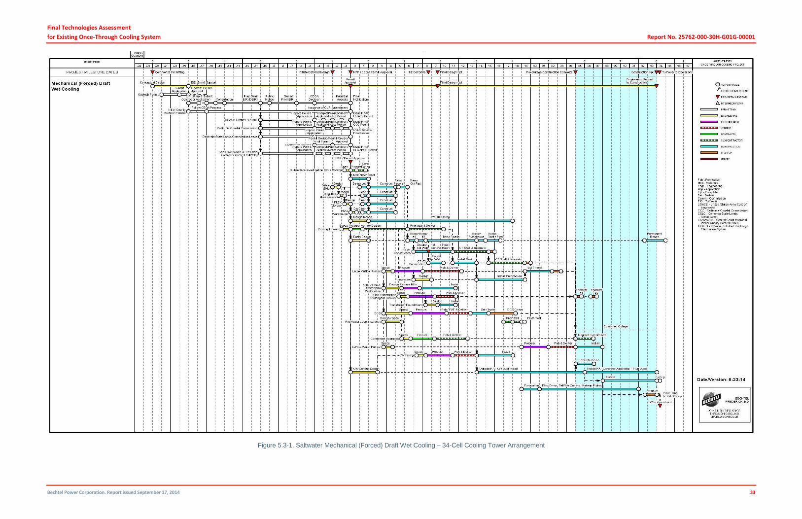
Final Technologies Assessment
for Existing Once-Through Cooling System Report No. 25762-000-30H-G01G-00001
Bechtel Power Corporation. Report issued September 17, 2014 33
Figure 5.3-1. Saltwater Mechanical (Forced) Draft Wet Cooling – 34-Cell Cooling Tower Arrangement

Final Technologies Assessment
for Existing Once-Through Cooling System Report No. 25762-000-30H-G01G-00001
Bechtel Power Corporation. Report issued September 17, 2014 34
Figure 5.3-2. Saltwater Mechanical (Forced) Draft Wet Cooling – 44-Cell Cooling Tower Arrangement

Final Technologies Assessment
for Existing Once-Through Cooling System Report No. 25762-000-30H-G01G-00001
Bechtel Power Corporation. Report issued September 17, 2014 35
5.5 Key Events that Start Prior to NTP
The NTP permitting process is essentially the same as in the previous schedules for the north closed-cycle cooling options. With one exception, the permitting activities leading up to the CEQA decision would take approximately 18 months instead of 16 months in response to the complications that saltwater towers would pose to the CEQA Review process, as noted in Section 3.8.2.5.
5.6 Critical Path Activities
The primary critical path for the saltwater cooling towers is driven by the concrete installation quantities. The concrete batch plant would be erected immediately following NTP. Follow-on critical activities would include construction of the new office building and facilities, demolition of existing facilities, excavation for the first cooling tower, and installation of ground support walls. These tasks would lead up to the first concrete milestone with the installation of the basins for both of the cooling towers. The critical path would continue through the construction of the pumphouse and CW duct installation outside the protected area. Three months after the start of the dual-unit outage, the concrete duct would be installed inside the protected area, followed with backfill, testing, and turnover to owner plant operations.
5.7 Outage Work
As shown on Figures 5.3-1 and 5.3-2, the dual-unit outages will last 27 months for both Case 1 and Case 1B. To minimize the impact to plant operations as much as possible, all possible pre-outage work will be completed prior to starting the outage. Additionally, the outage work will be performed on a 24/7 basis. The durations are based on the production rates required for the excavation quantities and installation of the CW conduit to the west of the plant. Major activities include excavation, demolition of existing concrete conduit, and installation of new concrete duct, tie-ins, backfill, and startup.
5.8 Schedule Risks
The schedule risks that have been identified are summarized below:
CEQA Final Decision – Delays in receipt of the CEQA Final Decision will delay key equipment procurement and subcontract awards, which, in turn, will delay the start of physical work.
EIR Preparation – The closed-cycle cooling system will require the preparation of an EIR, which has the potential to significantly extend the permitting process, depending on the EIR extensions of public review and comment periods and difficulties in responding to subsequent information requests.
Possible Litigation Schedule Impacts – While litigation schedule impacts have not been included, a nominal 1-year appeal period was assumed.
Vendor/Subcontractor Schedule Variation – While efforts have been made to appropriately forecast lead times and subcontract durations, there is a risk for variation due to market conditions and other external factors until final contracts are awarded.
Unknown Underground Conditions – Unknown underground conditions, particularly within the footprint of the operating units, could adversely affect the construction schedule.
Labor Availability – Availability of qualified labor could negatively affect the construction durations assumed in the schedule.

Final Technologies Assessment
for Existing Once-Through Cooling System Report No. 25762-000-30H-G01G-00001
Bechtel Power Corporation. Report issued September 17, 2014 36
6.0 Estimate Development
6.1 Estimate Overview
For this study, Bechtel implemented its proprietary Estimating Process Integration and Control (EPIC) estimating process to develop the costs for the DCPP, consistent with the Association for Advancement of Cost Engineers International (AACEI) Class 3 estimating standard defined in Section 1.2 of the AACEI standard. The estimating methodology used to develop the costs is the same as the one that would be used for any large and complex project. Bechtel used our proprietary cost database developed from new generation, power uprate, and capital equipment replacement project experience. In addition, Bechtel applied our fossil plant estimating experience to support the estimating of similar scope items such as the design and construction of similar cooling water intake structures.
The estimate is founded on scope developed by Engineering and refined by Construction and Estimating. Engineering completed the design in the range of 10% to 15% by evaluating differences from the designs developed for the technologies north of the plant, which yielded the conceptual quantities for the commodities used to develop the estimate. Construction refined the execution strategy based on the quantities and to meet the schedule requirements, which formed the basis for the development of craft labor productivity and craft labor wage rates, and identification of the specialty subcontracts required for the performance of the scope of work. The local craft labor conditions were investigated and craft wage rate information was secured, which was used to develop the labor wages and potential craft incentives to attract and retain qualified craft. Equipment supply was investigated to understand current equipment supply pricing. Equipment supply and install was investigated for the specialty subcontracts identified as part of execution strategy, to understand current equipment supply and installation pricing. This provided the total estimate for the direct cost component in the EPIC model.
The indirect cost component, such as startup labor, was estimated based on the scope of work as defined by Engineering. Engineering services labor was estimated based the engineering effort necessary to complete the design. The balance of cost components such as distributable cost, indirect cost, other home office services, and other costs (e.g., insurance, taxes, etc.) was estimated using the Bechtel proprietary database capturing actual cost experience from other projects of similar scope and size. The estimates are based on overnight pricing and exclude escalation. The project price includes a nominal fee for the contractor to perform the scope of work.
6.2 Estimate Classification
The estimate has been prepared in accordance with AACEI 18R-97: Cost Estimate Classification System – As Applied in Engineering, Procurement, and Construction for the Process Industries. The estimates provided in this report for the south parking lot options are being classified as Class 3 estimates.
According to AACEI, “Class 3 estimates are generally prepared to form the basis for budget authorization, appropriation, and/or funding. As such, they typically form the initial control estimate against which all actual costs and resources will be monitored. Typically, engineering is from 10% to 40% complete, and would comprise at a minimum the following: process flow diagrams, utility flow diagrams, preliminary piping and instrument diagrams, plot plan, developed layout drawings, and essentially complete engineered process and utility equipment lists.”

Final Technologies Assessment
for Existing Once-Through Cooling System Report No. 25762-000-30H-G01G-00001
Bechtel Power Corporation. Report issued September 17, 2014 37
According to AACEI, the estimating methodology for “Class 3 estimates generally involve more deterministic estimating methods than stochastic methods. They usually involve predominant use of unit cost line items, although these may be at an assembly level of detail rather than individual components. Factoring and other stochastic methods may be used to estimate less-significant areas of the project.”
According to AACEI, the expected accuracy range for Class 3 estimates are –10% to –20% on the low side, and +10% to +30% on the high side, depending on the technological complexity of the project, appropriate reference information, and other risks (after inclusion of an appropriate contingency determination). Ranges could exceed those shown if there are unusual risks.”
Following the methodology outlined in Section 6.1 and the estimate standards outlined in this section, the cost estimate details for each of the cases were developed and are provided in Section 6.3. A summary both cases of this technology is provided in Table 6.3-1.
6.3 Estimate Summary
The estimates for both cases of this technology are summarized in Table 6.3-1.
Table 6.3-1. Technology Estimate Summary
Technology
Project Cost in Billions
PG&E Costs in Billions
Grand Total in Billions
Case 1 – 44-Cell Wet Mechanical (Forced) Draft Cooling
$3.1 – $4.9 $3.1 $6.2 – $8.0
Case 1B – 34-Cell Wet Mechanical (Forced) Draft Cooling
$3.1 – $4.8 $3.1 $6.2 – $7.9
6.3.1 Estimate Summary Explained
The estimate summary is explained in Table 6.3-2. Separate estimate summaries for each case are provided in Sections 6.3.2 and 6.3.3.
The summary-level reconciliation for the differences between the previous wet mechanical (forced) draft cooling and the current 44-cell cooling case are provided in Table 6.3-2.

Final Technologies Assessment
for Existing Once-Through Cooling System Report No. 25762-000-30H-G01G-00001
Bechtel Power Corporation. Report issued September 17, 2014 38
Table 6.3-2. Estimate Summary Level Reconciliation for 44-Cell Cooling Case
Cost Category ($ x 1,000,000)
44 Cell Tower
Previous Wet Mechanical
(Forced) Draft Cooling
Delta Comments
Direct Costs 1,415 3,366 (1,951) The key drivers reducing the direct cost are as follows:
a. Mountain excavation is not required due to relocation of the cooling tower to the south parking lot location.
b. Desalinization equipment is not required due to use of saltwater cooling towers.
c. Recycle water transport and treatment equipment is not required.
d. The change in type of cooling tower resulted in a reduction in costs, which were partly offset by the added construction costs associated with the location (south parking lot), resulting a net cost reduction.
e. Infrastructure costs associated with relocation of existing buildings, new roads, etc. resulted in additional costs.
f. Permitting, including the 84 miles of additional road, resulted in additional costs.
It is important to note the majority of the reduction in costs were associated with subcontract costs from mountain excavation and equipment costs from desalinization and recycle water transport. The reduction in direct labor costs were minimal, which primarily drives the indirect and services costs. The relative relationship between the material, direct labor, and subcontract costs is shown in Figure 6.3-1. The scope of mountain excavation previously was isolated and a prime candidate for specialty earth moving subcontractor work. However, with the revised cooling tower location, the excavation execution plan requires close coordination with supporting buried utilities, including saltwater lines, etc. This work is a prime candidate for direct-hire work and not subcontracting. The estimate is based on this execution approach.
Indirects and Services
1,388 1,521 (133) At a summary level, it appears that direct costs are reduced by 60% while indirect and services costs are only reduced by 10%. As noted previously, the indirects and services are driven by the direct-hire labor hours. Since the majority of reduction in direct costs were due to material and subcontracts, the reduction in indirects and services is not consistent when looked at from a reduction in cost perspective. The net reduction in indirects and services cost is driven by the net reduction in direct-hire labor hours, which is minimal for the two cases. The limited change in direct-hire labor cost is primarily associated with the following scope changes for the two cases:
a. Reduced scope for the recycle water transport (~26 miles of piping).
b. Reduced scope for the installation of desalinization equipment.
c. Added scope of additional site work and concrete to accommodate the cooling towers at the new location (south parking lot).
Other 945 1,714 (769) These costs were estimated on the same basis as the previous wet mechanical estimate and based on net reduced direct, indirect, and services costs; these costs are also reduced.
s/t 3,748 6,601 (2,853)
Owner Costs 3,112 3,067 45 The net increase in the owner costs is due to the following:
a. Increased outage schedule duration due to increased scope associated with revised cooling tower location (south parking lot).
b. Busing costs for plant staff due to relocation of existing buildings.
Total 6,860 9,668 (2,808)

Final Technologies Assessment
for Existing Once-Through Cooling System Report No. 25762-000-30H-G01G-00001
Bechtel Power Corporation. Report issued September 17, 2014 39
The summary-level reconciliation for the differences between the previous wet mechanical (forced) draft cooling and the current 34-cell cooling case are provided in Table 6.3-3.
Table 6.3-3. Estimate Summary Level Reconciliation for 34-Cell Cooling Case
Cost Category ($ x 1,000,000)
34 Cell Tower
Previous Wet Mechanical
(Forced) Draft Cooling
Delta Comments
Direct Costs 1,385 3,366 (1,981) The key drivers reducing the direct cost are as follows:
a. Mountain excavation is not required due to relocation of the cooling tower to the south parking lot location.
b. Desalinization equipment is not required due to use of saltwater cooling towers.
c. Recycle water transport and treatment equipment is not required.
d. The change in type of cooling tower resulted in a reduction of costs, which were partly offset by the added construction costs associated with the location (south parking lot), resulting a net cost reduction.
e. Infrastructure costs associated with relocation of existing buildings, new roads, etc. resulted in additional costs.
f. Permitting, including the 84 miles of additional road, resulted in additional costs.
It is important to note the majority of the reduction in costs were associated with subcontract costs from mountain excavation and equipment costs from desalinization and recycle water transport. The reduction in direct labor costs were minimal, which primarily drives the indirect and services costs. The relative relationship between the material, direct labor, and subcontract costs is shown in Figure 6.3-1. The scope of mountain excavation previously was isolated and a prime candidate for specialty earth moving subcontractor work. However, with the revised cooling tower location, the excavation execution plan requires close coordination with supporting buried utilities, including saltwater lines, etc. This work is a prime candidate for direct-hire work and not subcontracting. The estimate is based on this execution approach.
Indirects and Services
1,369 1,521 (152) At a summary level, it appears that direct costs are reduced by 60% while indirect and services costs are only reduced by 10%. As noted previously, the indirects and services are driven by the direct-hire labor hours. Since the majority of reduction in direct costs were due to material and subcontracts, the reduction in indirects and services is not consistent when looked at from a reduction in cost perspective. The net reduction in indirects and services cost is driven by the net reduction in direct-hire labor hours, which is minimal for the two cases. The limited change in direct-hire labor cost is primarily associated with the following scope changes for the two cases:
a. Reduced scope for the recycle water transport (~26 miles of piping).
b. Reduced scope for the installation of desalinization equipment.
c. Added scope of additional site work and concrete to accommodate the cooling towers at the new location (south parking lot).
Other 927 1,714 (787) These costs were estimated on the same basis as the previous wet mechanical estimate and based on net reduced direct, indirect, and services cost; these costs are also reduced.
s/t 3,681 6,601 (2,920)
Owner Costs 3,112 3,067 45 The net increase in the owner costs is due to the following:
a. Increased outage schedule duration due to increased scope associated with revised cooling tower location (south parking lot).
b. Busing costs for plant staff due to relocation of existing buildings.
Total 6,793 9,668 (2,877)
Final Technologies Assessment
for Existing Once-Through Cooling System Report No. 25762-000-30H-G01G-00001
Bechtel Power Corporation. Report issued September 17, 2014 40
Figure 6.3-1. Relative Weighting of Material, Direct Labor and Subcontracts Costs

Final Technologies Assessment
for Existing Once-Through Cooling System Report No. 25762-000-30H-G01G-00001
Bechtel Power Corporation. Report issued September 17, 2014 41
Table 6.3.1-1 Explanation of Technology Estimate Summary
DCPP South Parking Lot Cooling Cases
Estimate Summary
Description
Comments
Civil
Typical items included are material, labor, and subcontract costs for site work, foundation excavation and back fill, concrete, structural steel, and architectural as applicable.
Mechanical
Typical items included are material, labor and subcontract costs for cooling towers, rotating equipment, condenser upgrades, water treatment, tanks, and other mechanical equipment as applicable.
Piping
Typical items included are material, labor and subcontract costs for piping systems associated with raw water, service, and fire water systems as applicable.
Electrical and Instrumentation Controls
Typical items included are material, labor and subcontract costs associated with instrumentation, electrical equipment, transmission lines, switchyard, and electrical bulks as applicable.
Traffic and Logistics
Includes freight costs for materials.
TOTAL DIRECT COST
Other Field Costs (Field Non-manual, Craft Distributables)
Typical Items included are field craft indirect labor (such as temporary construction, housekeeping, tool room management, etc.) and materials (such as small tools, consumables, construction equipment, cranes, craft break trailer, office trailers, etc.), field non-manual labor (such as craft supervision, field engineering, safety, quality, field project controls, etc.) and their other direct costs (such as computers, internet, office supplies, business travel, relocation and living costs, etc.).
Engineering Services
Includes engineering and other home office services costs.
TOTAL CONSTRUCTED COST
Other Costs (Securities, Insurances, Taxes Warranties and Permits)
Insurances, securities, sales taxes, construction permits, etc.
TOTAL COST
Contingency expected in range
Appropriate contingency for unknowns.
TOTAL PROJECT COST
Fee Contractor fee.
PG&E Provided Owner Costs
Project oversight, security oversight and modifications, plant shutdown and startup costs, annual increase in station operation and maintenance costs, simulator update, cost of capital, costs of busing plant personnel and of remote parking lot for plant personnel.
TOTAL PROJECT PRICE

Final Technologies Assessment
for Existing Once-Through Cooling System Report No. 25762-000-30H-G01G-00001
Bechtel Power Corporation. Report issued September 17, 2014 42
6.3.2 Estimate Summary for Case 1 – 44-Cell Wet Mechanical (Forced) Draft Cooling Towers
The estimate for the 44-cell wet mechanical (forced) draft cooling is summarized in Table 6.3.2-1.
Table 6.3.2-1. 44-Cell Wet Mechanical (Forced) Draft Cooling Estimate Summary

Final Technologies Assessment
for Existing Once-Through Cooling System Report No. 25762-000-30H-G01G-00001
Bechtel Power Corporation. Report issued September 17, 2014 43
6.3.3 Estimate Summary for Case 1B – 34-Cell Wet Mechanical (Forced) Draft Cooling Towers
The estimate for the 34-cell wet mechanical (forced) draft cooling is summarized in Table 6.3.3-1.
Table 6.3.3-1. 34-Cell Wet Mechanical (Forced) Draft Cooling Estimate Summary
DCPP South Lot Parking Lot
34 Cells Cooling Tower- Wet Mechanical (Forced) Draft CoolingEstimate Summary
Description Total Cost
--------------------------------------------------------------------------------------------------- --------------- ------------------------ --------------- ----------------------------
Civil $1,002,304,000
Site Work $590,349,000
Concrete Related $335,046,000
Structural Steel Work $6,592,000
Architectural $70,317,000
Mechanical $195,830,000
Rotating Equipment $37,518,000
Condenser / Cooling Tower $157,954,000
Water Treatment and Tanks $358,000
Piping $90,745,000
Electrical and Instrumentation Controls $89,775,000
Instrumentation $2,623,000
Electrical Equipment $19,954,000
Transmission Lines & Switch Yard $26,200,000
Electrical Bulks $40,998,000
Traffic and Logistics $6,258,000
--------------------------------------------------------------------------------------------------- --------------- ------------------------ --------------- ----------------------------
TOTAL DIRECT COST $1,384,912,000
Field Indirect Costs $527,803,000
Field Services $785,353,000
Home Office Services * $55,362,000
------------------------------------------------------------------------------------------------------------------------------------------------------------------------------------------
TOTAL CONSTRUCTED COST $2,753,430,000
Other Costs (Securities, Insurances, Warranties, Taxes and Permits) $138,958,000
------------------------------------------------------------------------------------------------------------------------------------------------------------------------------------------
TOTAL COST $2,892,388,000
Contingency is expected in range 15% to 25% $500,135,000
------------------------------------------------------------------------------------------------------------------------------------------------------------------------------------------
TOTAL CONTRACTOR COST (Using Higher Contingency) $3,392,523,000
Fee $288,364,000
=============================================================================================
TOTAL CONTRACTOR PRICE $3,680,887,000
Replacement Power Costs $1,889,896,000
PG&E Provided Owner Costs :
Project Oversight $184,044,000
Security Oversight and Security Modifications $38,000,000
Plant Shut Down and Start Up Costs $100,000,000
Annual Increase in Station Operation and Maintenance Costs $9,400,000
Simulator Update $5,000,000
Cost of Capital $834,000,000
Bussing Costs (Plant Personnel Only) $41,215,000
Parking Lot Costs (12 acres for 1,200 vehicle spaces for Plant Personnel Only) $8,800,000
TOTAL PROJECT COSTS $6,791,242,000
From To
CONTRACTOR PRICE ACCURACY RANGE ( - 20% TO + 30% ) $3,055,136,000 to $4,785,153,000
$4,266,795,000 $5,996,812,000
Notes: $4,267 $5,997
1). * Includes PG&E Provided Costs for NRC Review of Environmental Impact Statement
2). Project costs include $2.50 to $5.50 per craft hour for labor incentives to attract qualified workers
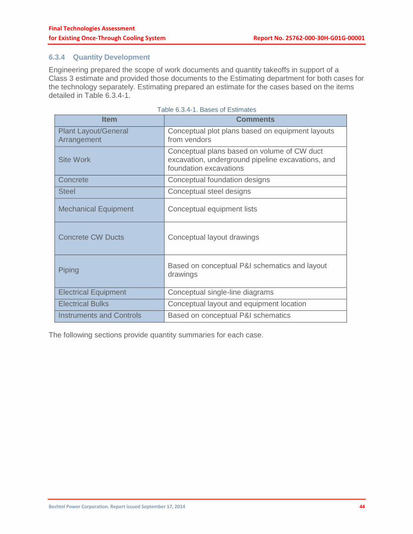
Final Technologies Assessment
for Existing Once-Through Cooling System Report No. 25762-000-30H-G01G-00001
Bechtel Power Corporation. Report issued September 17, 2014 44
6.3.4 Quantity Development
Engineering prepared the scope of work documents and quantity takeoffs in support of a Class 3 estimate and provided those documents to the Estimating department for both cases for the technology separately. Estimating prepared an estimate for the cases based on the items detailed in Table 6.3.4-1.
Table 6.3.4-1. Bases of Estimates
Item Comments
Plant Layout/General Arrangement
Conceptual plot plans based on equipment layouts from vendors
Site Work Conceptual plans based on volume of CW duct excavation, underground pipeline excavations, and foundation excavations
Concrete Conceptual foundation designs
Steel Conceptual steel designs
Mechanical Equipment Conceptual equipment lists
Concrete CW Ducts Conceptual layout drawings
Piping Based on conceptual P&I schematics and layout drawings
Electrical Equipment Conceptual single-line diagrams
Electrical Bulks Conceptual layout and equipment location
Instruments and Controls Based on conceptual P&I schematics
The following sections provide quantity summaries for each case.

Final Technologies Assessment
for Existing Once-Through Cooling System Report No. 25762-000-30H-G01G-00001
Bechtel Power Corporation. Report issued September 17, 2014 45
6.3.5 Case 1 – 44-Cell Wet Mechanical (Forced) Draft Cooling
The 44-cell wet mechanical (forced) draft cooling quantities are summarized in Table 6.3.5-1.
Table 6.3.5-1. 44-Cell Quantity Summary

Final Technologies Assessment
for Existing Once-Through Cooling System Report No. 25762-000-30H-G01G-00001
Bechtel Power Corporation. Report issued September 17, 2014 46
6.3.6 Case 1B – 34-Cell Wet Mechanical (Forced) Draft Cooling
The 34-cell wet mechanical (forced) draft cooling quantities are summarized in Table 6.3.6-1.
Table 6.3.6-1. 34-Cell Quantity Summary

Final Technologies Assessment
for Existing Once-Through Cooling System Report No. 25762-000-30H-G01G-00001
Bechtel Power Corporation. Report issued September 17, 2014 47
6.3.7 Direct Material and Subcontract Pricing
6.3.7.1 Wet Mechanical (Forced) Cooling Technology Supply Bids
Wet mechanical cooling technology supplier bids used for Cases 1 and 1B are highlighted below (all are from the previous closed-cycle cooling technologies study):
FRP
Electrical transformers
Condenser upgrades
Vertical pumps
Butterfly valves
The pricing for the balance of equipment and bulk materials was based on the pricing used in the main report. That pricing was based on actual pricing from current projects being built in 2013.
Freight costs are included at 6% of applicable equipment and bulk material costs for all options based on historical experience.
6.3.8 Construction
6.3.8.1 Direct Craft Labor Hours
Direct craft hours for each option were estimated based on standard labor installation rates appropriate for the work involved plus adjustments for the following:
Work in an operating nuclear facility
Work within protected areas
Congestion and interferences
Design complexities
Time needed to transport labor on buses to and from the plant
Labor efficiencies due to work schedules
Outage work efficiencies
Safety-related training classes
6.3.8.2 Craft Labor Wages
Craft wages were estimated on the same basis as the main report which was based on a May 2013 wage survey of the prevailing union local agreements in the southern California area. As was the case for the main report, labor costs were developed based on an anticipated work schedule to minimize schedule duration. It is assumed that labor fatigue rules do not apply for this scope. For scheduled non-outage-related work, craft wages are based on two shifts working 10-hour days, 5 days per week. For scheduled outage-related work, craft wages are based on two shifts working 12-hour days, 7 days per week. The cooling tower technologies were priced as a combination of non-outage and outage work based on schedule requirements. Travel incentives were included in the estimate to attract and retain qualified craft workers.

Final Technologies Assessment
for Existing Once-Through Cooling System Report No. 25762-000-30H-G01G-00001
Bechtel Power Corporation. Report issued September 17, 2014 48
6.3.8.3 Field Indirect Costs
Construction field indirect material costs (e.g., construction equipment, small tools, purchased utilities required during the construction period, office trailers, temporary buildings, craft labor change facilities, and craft busing costs) are based on ratios of indirect materials to direct labor hours from current and historical projects worked in existing nuclear facilities.
Field indirect labor hours were estimated as a percentage of direct craft labor hours based on review of ratios from current and historical projects worked in existing nuclear facilities.
Startup field indirect material costs (e.g., vendor testing services, flushes, testing equipment, tools, vehicles, and other consumable supplies) were developed based on scope of work documents and engineered quantities used in the main report for the wet mechanical (forced) draft closed-cycle cooling option.
Startup craft labor hours were estimated based on the wet mechanical (forced) draft closed-cycle cooling option in the main report. It is assumed that startup craft labor hours are the same for the current study.
6.3.9 Home Office Services
The Engineering hours were estimated based on the hours required for the wet mechanical (forced) draft closed-cycle cooling option in the main report.
Other home office services hours (e.g., Project Management, Project Controls, Procurement, Administrative Services, Accounting, Information Systems, Quality Management, Construction department functional support, Startup department functional support, and Contracts Management department functional support) are the same as was used in the main report which were estimated on current and historical projects worked in existing nuclear plants.
6.3.10 Engineering Services Subcontracts
Geotechnical subsurface and topographical studies, National Fire Protection Association inspection services, seismic analysis services, traffic consultant services, and archeological consultant services were assumed to be required and priced based on historical costs for similar services. Costs for USNRC review of the environmental impact statement were provided by PG&E.
6.3.11 Procurement Services Subcontracts
Bechtel supplier quality inspection services were priced based on historical data.
6.3.12 Field Non-manual
Based on professional skill sets required for work in a nuclear plant, for each option field, non-manual hours for field administration and direct supervision of the work involved for each option were estimated as a percentage of craft hours based on current and historical projects.
Field staff relocation costs were estimated based on actual domestic employment conditions from similar historical projects in the same geographical area.

Final Technologies Assessment
for Existing Once-Through Cooling System Report No. 25762-000-30H-G01G-00001
Bechtel Power Corporation. Report issued September 17, 2014 49
6.3.13 Startup
Based on the work involved and professional skill sets required for each technology, Startup developed non-manual staffing plans for field administration and direct startup supervision of startup of all equipment and systems.
Relocation costs for the field startup staff were estimated based on the actual domestic employment conditions from similar historical projects in the same geographical area.
6.3.14 Other Costs
6.3.14.1 Insurances
Umbrella coverage is assumed to be included as part of workmen’s compensation insurance built into craft labor costing rates.
Builder’s risk is based on typical rates for work in nuclear plants.
Marine transit coverage is based on typical industry rates.
6.3.14.2 Securities
A letter of credit for 120 months valued at 10% of project price is included for all options and is priced at 125 bps per annum.
A warranty letter of credit for 1 year valued at 5% of price is included for all options and is priced at 150 bps per annum.
6.3.14.3 Warranty
Costs have been included at 0.50% of total constructed cost.
6.3.14.4 Taxes
Taxes have been included at 7.5% of all field direct and field indirect materials.
6.3.14.5 Escalation
Costs have been excluded from the estimate, which is in 2013 dollars.
6.3.14.6 Contingency
Contingency included in the estimate is 18.1% the same as was calculated for the wet
mechanical (forced) draft option in the main report.
6.3.14.7 Replacement Power
Replacement power costs were provided by the Nuclear Review Committee and were
developed using California average market price based on forwards ($/MWh) of $46.76 per
MWh per E3’s 2013 forecast average energy price estimate (http:/www.ethree.com).
Based on a dual-unit outage period of 27 months the cost calculation is as follows:

Final Technologies Assessment
for Existing Once-Through Cooling System Report No. 25762-000-30H-G01G-00001
Bechtel Power Corporation. Report issued September 17, 2014 50
1,155 MW x 24 hours x 810 days x $46.76 MWh x 2 units x 0.9 capacity factor =
$1,889,896,000.