addendum - plans.adtechsupply.com
TRANSCRIPT

119 South 49th Avenue
Omaha, NE 68132
402. 551. 0800
HollandBasham.com
C:\Users\cthiele\Dropbox (HBA)\Projects\2021\21005 MCC FOC - Bldg 10 - Digital Library\ca\revisions\rev03add03-2021-08-
05\_originals\rev03add03-2021-08-05-arch narrative.docx
Addendum
Project Name: Fort Omaha Campus – Bldg 10 - Renovation
Project Address: 5300 N 30th St, Omaha, NE 68111
Project Number: 21005
Owner: Metropolitan Community College
Addendum #: 3, REV #3
Date: August 5, 2021
By: Corey Thiele, Holland Basham Architects
To: Project Bidders
This Addendum to the project bidding documents and attached reference drawings dated August 5, 2021,
issued to inform bidders of revisions to the bidding documents.
All related requirements contained in the original bidding documents, dated July 12, 2021 shall still apply to
this Addendum. The general character of the work specified in this Addendum shall be the same as
originally set forth in the applicable portions of the bidding documents for similar work, unless otherwise
specified in this Addendum. All additional work necessitated by this Addendum as required to complete
the work shall be included in the bids even though not particularly mentioned in this Addendum.
Description:
All questions, RFIs, and substitution requests received after the end of business on 8/4/21 have not been
considered. This will be the final addendum to the documents before the bid date.
Bid Question Responses
1. Existing membrane roof was installed in 2015 by McGinnis Roofing. It is a TPO roof manufactured
by Carlisle.
2. All work noted on Civil and Landscape sheets is part of Alternate #4. New front entry and
associated new footing (including excavation and replacement of sidewalk/plaza) are part of Base
Bid 01.
Specification
09 2116 – GYPSUM BOARD ASSEMBLIES
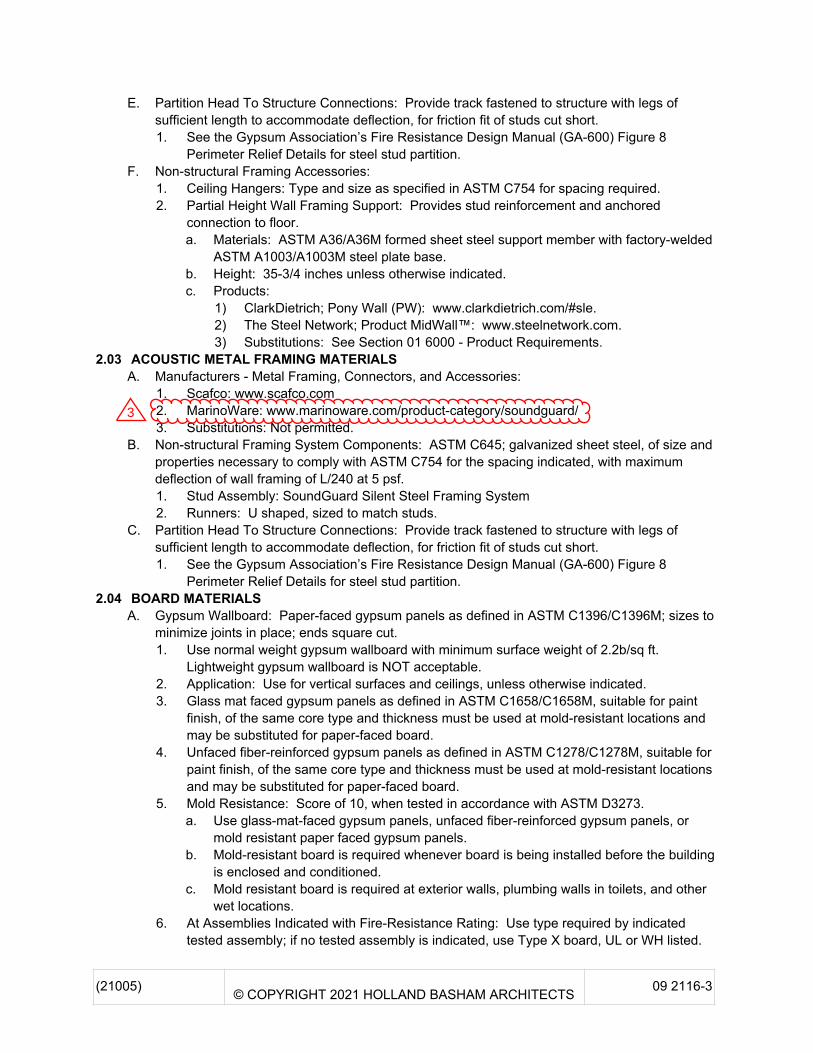
1. Add paragraph 2.03, A, 2 listing MarinoWare as an acceptable manufacturer of the SoundGuard
acoustic metal framing material.
12 2400 – WINDOW SHADES
1. Remove paragraph 1.01, B – Motor Controls.

C:\Users\cthiele\Dropbox (HBA)\Projects\2021\21005 MCC FOC - Bldg 10 - Digital Library\ca\revisions\rev03add03-2021-08-
05\_originals\rev03add03-2021-08-05-arch narrative.docx
2. Remove entire paragraph 2.04 MOTOR CONTROLS, A through C.
Architectural
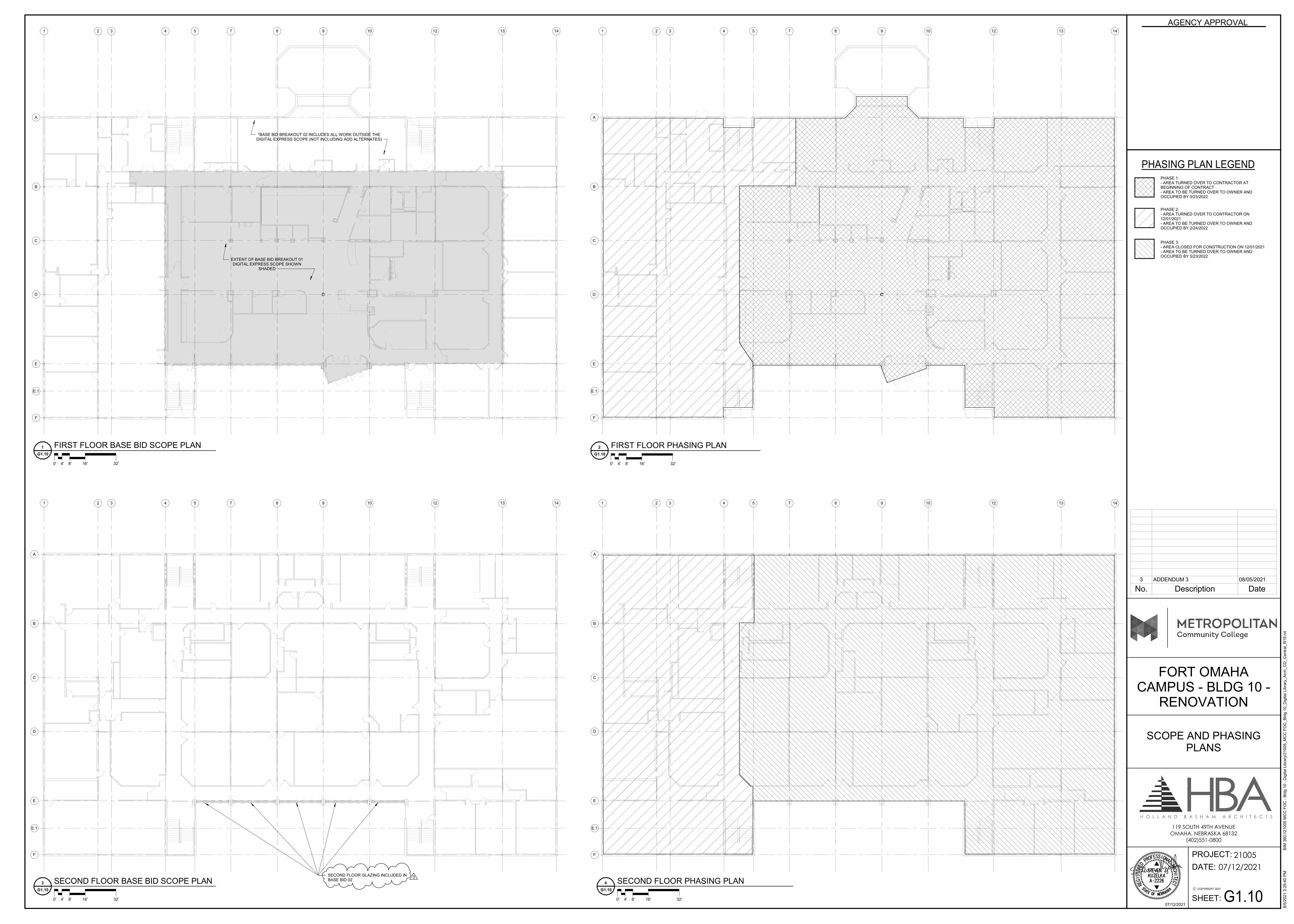
G1.10 – SCOPE AND PHASING PLANS
1. Revise note on 3/G1.10 – SECOND FLOOR BASE BID SCOPE PLAN. Second floor glazing
replacement to be part of Base Bid 02.
A2.12 – FRAME TYPES
1. Revise frame material on frames F4, F5, F6, F7, F8, F9, F10, F11, and F15 to ALSF-2.
2. Remove detail reference 11/A2.21 and replace with 4/A2.21 on frame types F4, F6, F7, F8, and F9.
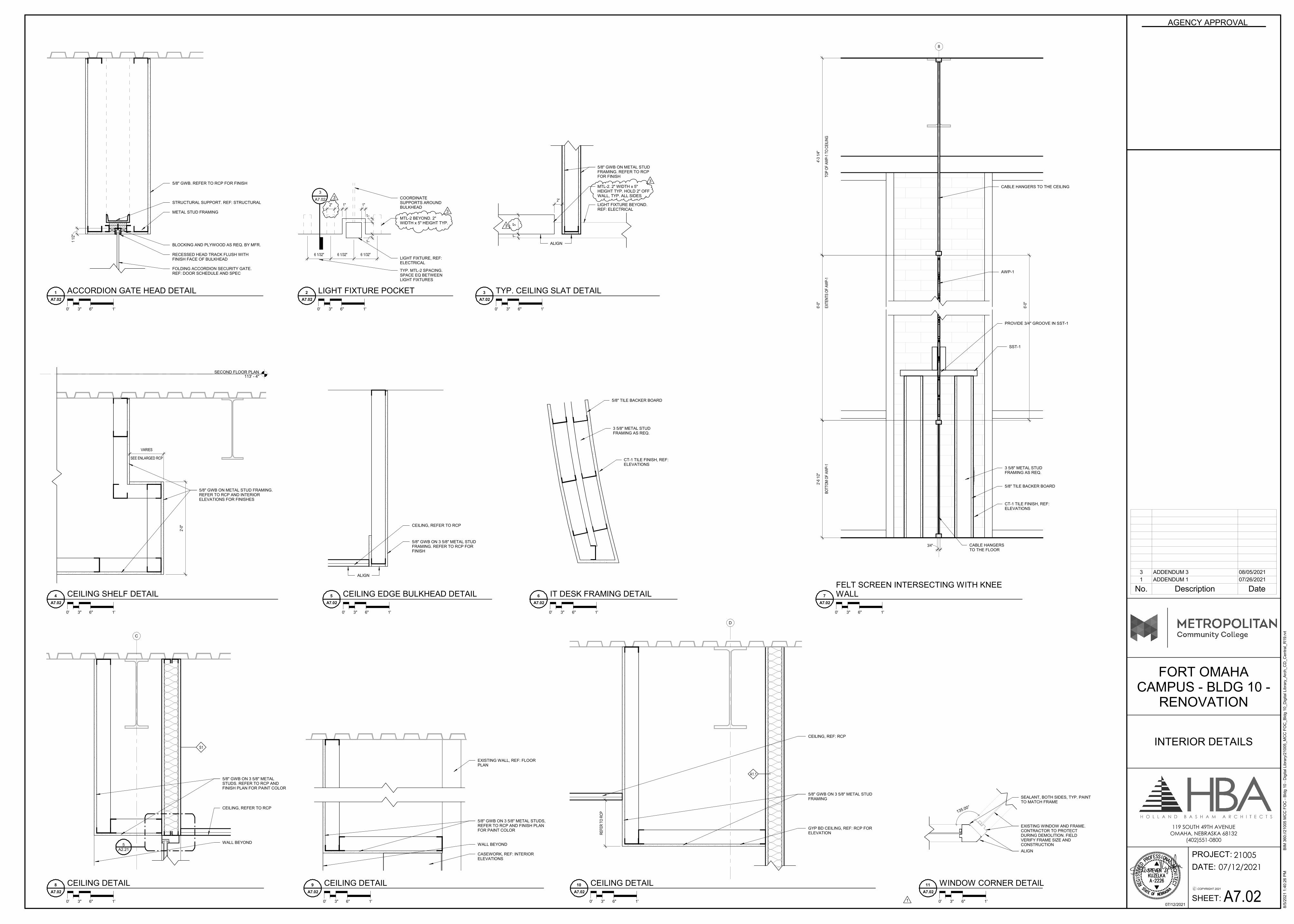
A7.02 – INTERIOR DETAILS
1. Add dimensions for MTL-2. Each slat to be 2” wide x 5” tall.
Attachment:
1. Pre-bid RFI from MCL with Holland Basham Architects responses included.
REQUEST FOR INFORMATION
14124 Industrial Road
Omaha, NE 68144-3332
DATE: NO.
ARCHITECT: PROJECT:
ATTN:
SUBJECT:
MCL Contact:
REQUEST:
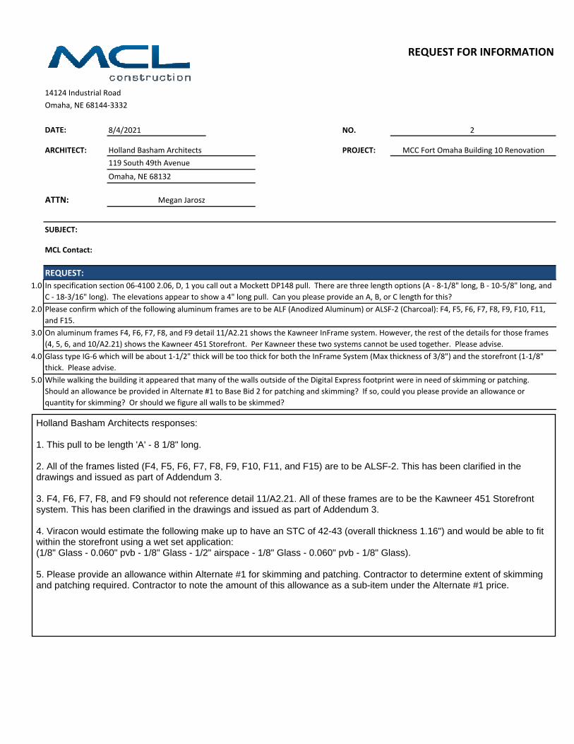
1.0
2.0
3.0
4.0
5.0
On aluminum frames F4, F6, F7, F8, and F9 detail 11/A2.21 shows the Kawneer InFrame system. However, the rest of the details for those frames
(4, 5, 6, and 10/A2.21) shows the Kawneer 451 Storefront. Per Kawneer these two systems cannot be used together. Please advise.
Glass type IG-6 which will be about 1-1/2" thick will be too thick for both the InFrame System (Max thickness of 3/8") and the storefront (1-1/8"
thick. Please advise.
While walking the building it appeared that many of the walls outside of the Digital Express footprint were in need of skimming or patching.
Should an allowance be provided in Alternate #1 to Base Bid 2 for patching and skimming? If so, could you please provide an allowance or
quantity for skimming? Or should we figure all walls to be skimmed?
Megan Jarosz
In specification section 06-4100 2.06, D, 1 you call out a Mockett DP148 pull. There are three length options (A - 8-1/8" long, B - 10-5/8" long, and
C - 18-3/16" long). The elevations appear to show a 4" long pull. Can you please provide an A, B, or C length for this?
Please confirm which of the following aluminum frames are to be ALF (Anodized Aluminum) or ALSF-2 (Charcoal): F4, F5, F6, F7, F8, F9, F10, F11,
and F15.
8/4/2021 2
Holland Basham Architects MCC Fort Omaha Building 10 Renovation
119 South 49th Avenue
Omaha, NE 68132
Holland Basham Architects responses:
1. This pull to be length 'A' - 8 1/8" long.
2. All of the frames listed (F4, F5, F6, F7, F8, F9, F10, F11, and F15) are to be ALSF-2. This has been clarified in thedrawings and issued as part of Addendum 3.
3. F4, F6, F7, F8, and F9 should not reference detail 11/A2.21. All of these frames are to be the Kawneer 451 Storefrontsystem. This has been clarified in the drawings and issued as part of Addendum 3.
4. Viracon would estimate the following make up to have an STC of 42-43 (overall thickness 1.16") and would be able to fitwithin the storefront using a wet set application:(1/8" Glass - 0.060" pvb - 1/8" Glass - 1/2" airspace - 1/8" Glass - 0.060" pvb - 1/8" Glass).
5. Please provide an allowance within Alternate #1 for skimming and patching. Contractor to determine extent of skimmingand patching required. Contractor to note the amount of this allowance as a sub-item under the Alternate #1 price.

(21005) © COPYRIGHT 2021 HOLLAND BASHAM ARCHITECTS 09 2116-1
SECTION 09 2116GYPSUM BOARD ASSEMBLIES
PART 1 GENERAL1.01 SECTION INCLUDES
A. Performance criteria for gypsum board assemblies.B. Metal stud wall framing.C. Metal channel ceiling framing.D. Acoustic insulation.E. Cementitious backing board.F. Gypsum wallboard.G. Joint treatment and accessories.H. Acoustic (sound-dampening) wall and ceiling board.
1.02 RELATED REQUIREMENTSA. Section 06 1000 - Rough Carpentry: Building framing, wood blocking, and sheathing.B. Section 06 1000 - Rough Carpentry: Building framing and sheathing.C. Section 07 2500 - Weather Barriers: Water-resistive barrier over sheathing.D. Section 07 8400 - Firestopping: Top-of-wall assemblies at fire-resistance-rated walls.E. Section 07 9200 - Joint Sealants: Sealing acoustical gaps in construction other than gypsum
board or plaster work.1.03 REFERENCE STANDARDS
A. ANSI A108.11 - American National Standard Specifications for Interior Installation ofCementitious Backer Units 2018.
B. ANSI A118.9 - American National Standard Specifications for Test Methods and Specificationsfor Cementitious Backer Units 1999 (Reaffirmed 2016).
C. ASTM A36/A36M - Standard Specification for Carbon Structural Steel 2014.D. ASTM A1003/A1003M - Standard Specification for Steel Sheet, Carbon, Metallic- and
Nonmetallic-Coated for Cold-Formed Framing Members 2015.E. ASTM C475/C475M - Standard Specification for Joint Compound and Joint Tape for Finishing
Gypsum Board 2017.F. ASTM C645 - Standard Specification for Nonstructural Steel Framing Members 2018.G. ASTM C665 - Standard Specification for Mineral-Fiber Blanket Thermal Insulation for Light
Frame Construction and Manufactured Housing 2017.H. ASTM C754 - Standard Specification for Installation of Steel Framing Members to Receive
Screw-Attached Gypsum Panel Products 2020.I. ASTM C840 - Standard Specification for Application and Finishing of Gypsum Board 2020.J. ASTM C954 - Standard Specification for Steel Drill Screws for the Application of Gypsum Panel
Products or Metal Plaster Bases to Steel Studs From 0.033 in. (0.84 mm) to 0.112 in. (2.84mm) in Thickness 2018.
K. ASTM C1002 - Standard Specification for Steel Self-Piercing Tapping Screws for Application ofGypsum Panel Products or Metal Plaster Bases to Wood Studs or Steel Studs 2020.
L. ASTM C1047 - Standard Specification for Accessories For Gypsum Wallboard and GypsumVeneer Base 2019.
M. ASTM C1278/C1278M - Standard Specification for Fiber-Reinforced Gypsum Panel 2017.N. ASTM C1288 - Standard Specification for Discrete Non-Asbestos Fiber-Cement Interior
Substrate Sheets 2017.O. ASTM C1325 - Standard Specification for Fiber-Mat Reinforced Cementitious Backer Units
2019.P. ASTM C1396/C1396M - Standard Specification for Gypsum Board 2017.Q. ASTM C1658/C1658M - Standard Specification for Glass Mat Gypsum Panels 2019, with
Ediorial Revision (2020).

( 21005 ) © COPYRIGHT 2021 HOLLAND BASHAM ARCHITECTS 09 2116 - 2
R. ASTM D3273 - Standard Test Method for Resistance to Growth of Mold on the Surface ofInterior Coatings in an Environmental Chamber 2016.
S. ASTM E90 - Standard Test Method for Laboratory Measurement of Airborne SoundTransmission Loss of Building Partitions and Elements 2009 (Reapproved 2016).
T. ASTM E413 - Classification for Rating Sound Insulation 2016.U. GA-214 - Recommended Levels of Finish - Gypsum Board, Glass Mat and Fiber-Reinforced
Gypsum Panels 2015.V. GA-216 - Application and Finishing of Gypsum Panel Products 2016.W. GA-600 - Fire Resistance Design Manual 2015.
1.04 SUBMITTALSA. See Section 01 3000 - Administrative Requirements for submittal procedures.B. Shop Drawings: Indicate special details associated with fireproofing, control joint layout,
acoustic seals, and control joint layout .C. Product Data: Provide data on metal framing, gypsum board, accessories, and joint finishing
system.1.05 QUALITY ASSURANCE
A. Installer Qualifications: Company specializing in performing gypsum board installation andfinishing , with minimum three years of experience .
PART 2 PRODUCTS2.01 GYPSUM BOARD ASSEMBLIES
A. Provide completed assemblies complying with ASTM C840 and GA-216.1. See PART 3 for finishing requirements.
B. Interior Partitions, Indicated as Sound-Rated: Provide completed assemblies with the followingcharacteristics:1. Acoustic Attenuation: STC as indicated on drawings calculated in accordance with ASTM
E413, based on tests conducted in accordance with ASTM E90.C. Shaft Walls at HVAC Shafts: Provide completed assemblies with the following characteristics:
1. Air Pressure Within Shaft: Sustained loads of 5 lbf/sq ft with maximum mid-spandeflection of L/240.
2. Acoustic Attenuation: STC as indicated on the drawings calculated in accordance withASTM E413, based on tests conducted in accordance with ASTM E90.
2.02 METAL FRAMING MATERIALSA. Manufacturers - Metal Framing, Connectors, and Accessories:
1. ClarkDietrich : www.clarkdietrich.com/#sle.2. Marino : www.marinoware.com/#sle.3. MRI Steel Framing : www.mristeelframing.com.4. Substitutions: See Section 01 6000 - Product Requirements.
B. Non-structural Framing System Components: ASTM C645; galvanized sheet steel, of size andproperties necessary to comply with ASTM C754 for the spacing indicated, with maximumdeflection of wall framing of L/240 at 5 psf .1. Studs: C-shaped with flat or formed webs with knurled faces .2. Runners: U shaped, sized to match studs.3. Ceiling Channels: C-shaped.4. Furring Members: Hat-shaped sections, minimum depth of 7/8 inch.5. Resilient Furring Channels: See Section 09 2246 - Resilient Supports for Gypsum Board
Assemblies.C. Exterior Non-Loadbearing Studs and Furring for Application of Gypsum Board: As indicated on
the drawings.D. Shaft Wall Studs and Accessories: ASTM C645; galvanized sheet steel, of size and properties
necessary to comply with ASTM C754 and specified performance requirements.
( 21005 ) © COPYRIGHT 2021 HOLLAND BASHAM ARCHITECTS 09 2116 - 3
E. Partition Head To Structure Connections: Provide track fastened to structure with legs ofsufficient length to accommodate deflection, for friction fit of studs cut short .1. See the Gypsum Association’s Fire Resistance Design Manual (GA-600) Figure 8
Perimeter Relief Details for steel stud partition.F. Non-structural Framing Accessories:
1. Ceiling Hangers: Type and size as specified in ASTM C754 for spacing required.2. Partial Height Wall Framing Support: Provides stud reinforcement and anchored
connection to floor.a. Materials: ASTM A36/A36M formed sheet steel support member with factory-welded
ASTM A1003/A1003M steel plate base.b. Height: 35-3/4 inches unless otherwise indicated.c. Products:
1) ClarkDietrich; Pony Wall (PW): www.clarkdietrich.com/#sle.2) The Steel Network; Product MidWall™: www.steelnetwork.com .3) Substitutions: See Section 01 6000 - Product Requirements.
2.03 ACOUSTIC METAL FRAMING MATERIALSA. Manufacturers - Metal Framing, Connectors, and Accessories:
1. Scafco: www.scafco.com2. MarinoWare: www.marinoware.com/product-category/soundguard/3. Substitutions: Not permitted.
B. Non-structural Framing System Components: ASTM C645; galvanized sheet steel, of size andproperties necessary to comply with ASTM C754 for the spacing indicated, with maximumdeflection of wall framing of L/240 at 5 psf.1. Stud Assembly: SoundGuard Silent Steel Framing System2. Runners: U shaped, sized to match studs.
C. Partition Head To Structure Connections: Provide track fastened to structure with legs ofsufficient length to accommodate deflection, for friction fit of studs cut short .1. See the Gypsum Association’s Fire Resistance Design Manual (GA-600) Figure 8
Perimeter Relief Details for steel stud partition.2.04 BOARD MATERIALS
A. Gypsum Wallboard: Paper-faced gypsum panels as defined in ASTM C1396/C1396M; sizes tominimize joints in place; ends square cut.1. Use normal weight gypsum wallboard with minimum surface weight of 2.2b/sq ft.
Lightweight gypsum wallboard is NOT acceptable.2. Application: Use for vertical surfaces and ceilings, unless otherwise indicated.3. Glass mat faced gypsum panels as defined in ASTM C1658/C1658M, suitable for paint
finish, of the same core type and thickness must be used at mold-resistant locations andmay be substituted for paper-faced board.
4. Unfaced fiber-reinforced gypsum panels as defined in ASTM C1278/C1278M, suitable forpaint finish, of the same core type and thickness must be used at mold-resistant locationsand may be substituted for paper-faced board.
5. Mold Resistance: Score of 10, when tested in accordance with ASTM D3273.a. Use glass-mat-faced gypsum panels, unfaced fiber-reinforced gypsum panels, or
mold resistant paper faced gypsum panels .b. Mold-resistant board is required whenever board is being installed before the building
is enclosed and conditioned.c. Mold resistant board is required at exterior walls, plumbing walls in toilets, and other
wet locations .6. At Assemblies Indicated with Fire-Resistance Rating: Use type required by indicated
tested assembly; if no tested assembly is indicated, use Type X board, UL or WH listed.
3
( 21005 ) © COPYRIGHT 2021 HOLLAND BASHAM ARCHITECTS 09 2116 - 4
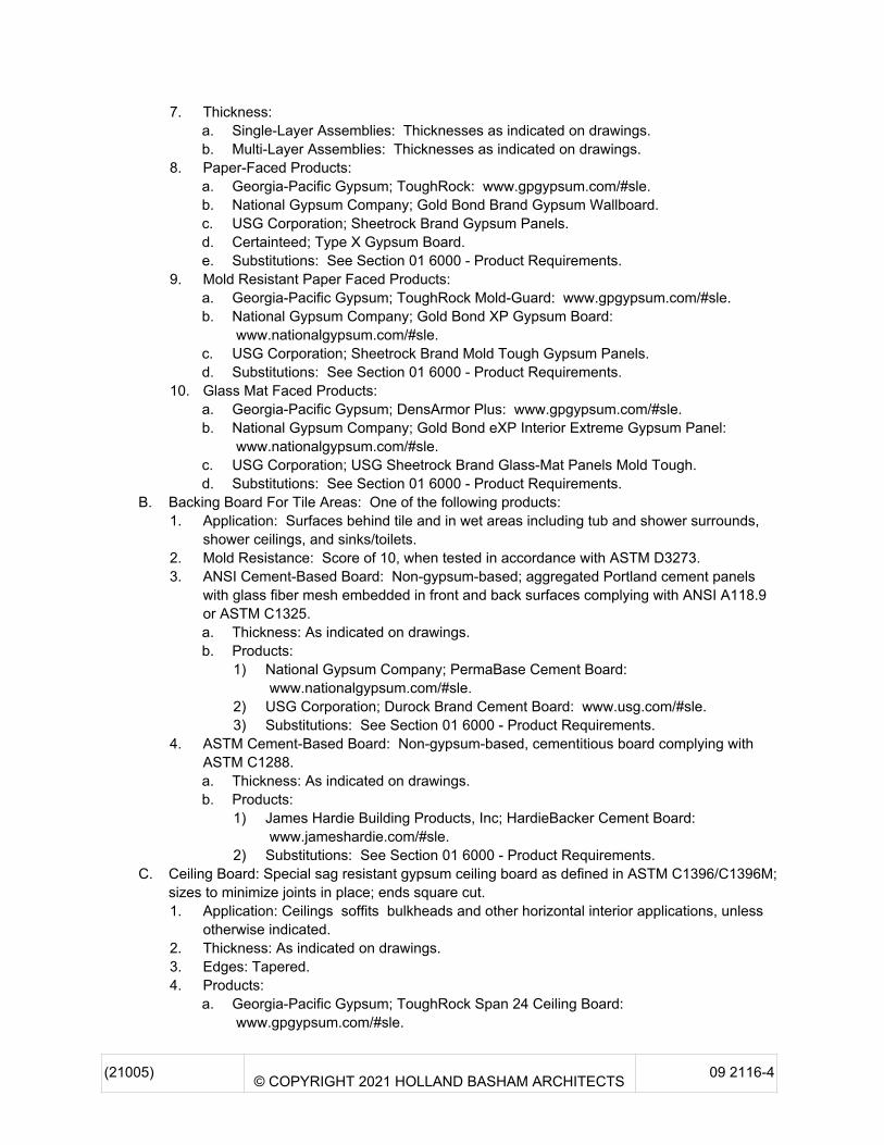
7. Thickness: a. Single-Layer Assemblies: Thicknesses as indicated on drawings.b. Multi-Layer Assemblies: Thicknesses as indicated on drawings.
8. Paper-Faced Products:a. Georgia-Pacific Gypsum; ToughRock: www.gpgypsum.com/#sle.b. National Gypsum Company; Gold Bond Brand Gypsum Wallboard.c. USG Corporation; Sheetrock Brand Gypsum Panels.d. Certainteed; Type X Gypsum Board.e. Substitutions: See Section 01 6000 - Product Requirements.
9. Mold Resistant Paper Faced Products:a. Georgia-Pacific Gypsum; ToughRock Mold-Guard: www.gpgypsum.com/#sle.b. National Gypsum Company; Gold Bond XP Gypsum Board:
www.nationalgypsum.com/#sle.c. USG Corporation; Sheetrock Brand Mold Tough Gypsum Panels.d. Substitutions: See Section 01 6000 - Product Requirements.
10. Glass Mat Faced Products:a. Georgia-Pacific Gypsum; DensArmor Plus: www.gpgypsum.com/#sle.b. National Gypsum Company; Gold Bond eXP Interior Extreme Gypsum Panel:
www.nationalgypsum.com/#sle.c. USG Corporation; USG Sheetrock Brand Glass-Mat Panels Mold Tough.d. Substitutions: See Section 01 6000 - Product Requirements.
B. Backing Board For Tile Areas: One of the following products:1. Application: Surfaces behind tile and in wet areas including tub and shower surrounds,
shower ceilings, and sinks/toilets.2. Mold Resistance: Score of 10, when tested in accordance with ASTM D3273.3. ANSI Cement-Based Board: Non-gypsum-based; aggregated Portland cement panels
with glass fiber mesh embedded in front and back surfaces complying with ANSI A118.9or ASTM C1325.a. Thickness: As indicated on drawings.b. Products:
1) National Gypsum Company; PermaBase Cement Board: www.nationalgypsum.com/#sle.
2) USG Corporation; Durock Brand Cement Board: www.usg.com/#sle.3) Substitutions: See Section 01 6000 - Product Requirements.
4. ASTM Cement-Based Board: Non-gypsum-based, cementitious board complying withASTM C1288.a. Thickness: As indicated on drawings.b. Products:
1) James Hardie Building Products, Inc; HardieBacker Cement Board: www.jameshardie.com/#sle.
2) Substitutions: See Section 01 6000 - Product Requirements.C. Ceiling Board: Special sag resistant gypsum ceiling board as defined in ASTM C1396/C1396M;
sizes to minimize joints in place; ends square cut.1. Application: Ceilings soffits bulkheads and other horizontal interior applications, unless
otherwise indicated.2. Thickness: As indicated on drawings.3. Edges: Tapered.4. Products:
a. Georgia-Pacific Gypsum; ToughRock Span 24 Ceiling Board: www.gpgypsum.com/#sle.
( 21005 ) © COPYRIGHT 2021 HOLLAND BASHAM ARCHITECTS 09 2116 - 5
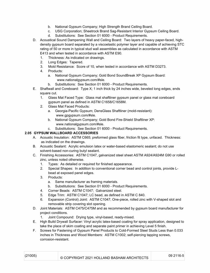
b. National Gypsum Company; High Strength Brand Ceiling Board.c. USG Corporation; Sheetrock Brand Sag-Resistant Interior Gypsum Ceiling Board.d. Substitutions: See Section 01 6000 - Product Requirements.
D. Acoustical Sound Dampening Wall and Ceiling Board: Two layers of heavy paper-faced, high-density gypsum board separated by a viscoelastic polymer layer and capable of achieving STCrating of 50 or more in typical stud wall assemblies as calculated in accordance with ASTME413 and when tested in accordance with ASTM E90.1. Thickness: As indicated on drawings.2. Long Edges: Tapered.3. Mold Resistance: Score of 10, when tested in accordance with ASTM D3273.4. Products:
a. National Gypsum Company; Gold Bond SoundBreak XP Gypsum Board: www.nationalgypsum.com/#sle.
b. Substitutions: See Section 01 6000 - Product Requirements.E. Shaftwall and Coreboard: Type X; 1 inch thick by 24 inches wide, beveled long edges, ends
square cut.1. Glass Mat Faced Type: Glass mat shaftliner gypsum panel or glass mat coreboard
gypsum panel as defined in ASTM C1658/C1658M.2. Glass Mat Faced Products:
a. Georgia-Pacific Gypsum; DensGlass Shaftliner (mold-resistant): www.gpgypsum.com/#sle.
b. National Gypsum Company; Gold Bond Fire-Shield Shaftliner XP: www.nationalgypsum.com/#sle.
c. Substitutions: See Section 01 6000 - Product Requirements.2.05 GYPSUM WALLBOARD ACCESSORIES
A. Acoustic Insulation: ASTM C665; preformed glass fiber, friction fit type, unfaced. Thickness: as indicated on the drawings .
B. Acoustic Sealant: Acrylic emulsion latex or water-based elastomeric sealant; do not usesolvent-based non-curing butyl sealant.
C. Finishing Accessories: ASTM C1047, galvanized steel sheet ASTM A924/A924M G90 or rolledzinc , unless noted otherwise.1. Types: As detailed or required for finished appearance.2. Special Shapes: In addition to conventional corner bead and control joints, provide L-
bead at exposed panel edges.3. Products:
a. Same manufacturer as framing materials.b. Substitutions: See Section 01 6000 - Product Requirements.
4. Corner Beads: ASTM C1047; Galvanized steel.5. Edge Trim: ASTM C1047; LC bead, as defined in ASTM C 840.6. Expansion (Control) Joint: ASTM C1047; One-piece, rolled zinc with V-shaped slot and
removable strip covering slot opening.D. Joint Materials: ASTM C475/C475M and as recommended by gypsum board manufacturer for
project conditions.1. Joint Compound: Drying type, vinyl-based, ready-mixed.
E. High Build Drywall Surfacer: Vinyl acrylic latex-based coating for spray application, designed totake the place of skim coating and separate paint primer in achieving Level 5 finish.
F. Screws for Fastening of Gypsum Panel Products to Cold-Formed Steel Studs Less than 0.033inches in Thickness and Wood Members: ASTM C1002; self-piercing tapping screws,corrosion-resistant.
( 21005 ) © COPYRIGHT 2021 HOLLAND BASHAM ARCHITECTS 09 2116 - 6
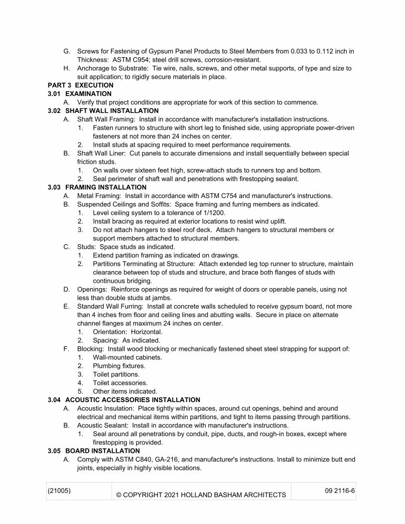
G. Screws for Fastening of Gypsum Panel Products to Steel Members from 0.033 to 0.112 inch inThickness: ASTM C954; steel drill screws, corrosion-resistant.
H. Anchorage to Substrate: Tie wire, nails, screws, and other metal supports, of type and size tosuit application; to rigidly secure materials in place.
PART 3 EXECUTION3.01 EXAMINATION
A. Verify that project conditions are appropriate for work of this section to commence.3.02 SHAFT WALL INSTALLATION
A. Shaft Wall Framing: Install in accordance with manufacturer's installation instructions.1. Fasten runners to structure with short leg to finished side, using appropriate power-driven
fasteners at not more than 24 inches on center.2. Install studs at spacing required to meet performance requirements.
B. Shaft Wall Liner: Cut panels to accurate dimensions and install sequentially between specialfriction studs.1. On walls over sixteen feet high, screw-attach studs to runners top and bottom.2. Seal perimeter of shaft wall and penetrations with firestopping sealant.
3.03 FRAMING INSTALLATIONA. Metal Framing: Install in accordance with ASTM C754 and manufacturer's instructions.B. Suspended Ceilings and Soffits: Space framing and furring members as indicated.
1. Level ceiling system to a tolerance of 1/1200.2. Install bracing as required at exterior locations to resist wind uplift.3. Do not attach hangers to steel roof deck. Attach hangers to structural members or
support members attached to structural members.C. Studs: Space studs as indicated .
1. Extend partition framing as indicated on drawings.2. Partitions Terminating at Structure: Attach extended leg top runner to structure, maintain
clearance between top of studs and structure, and brace both flanges of studs withcontinuous bridging.
D. Openings: Reinforce openings as required for weight of doors or operable panels, using notless than double studs at jambs.
E. Standard Wall Furring: Install at concrete walls scheduled to receive gypsum board, not morethan 4 inches from floor and ceiling lines and abutting walls. Secure in place on alternatechannel flanges at maximum 24 inches on center.1. Orientation: Horizontal.2. Spacing: As indicated.
F. Blocking: Install wood blocking or mechanically fastened sheet steel strapping for support of:1. Wall-mounted cabinets.2. Plumbing fixtures.3. Toilet partitions.4. Toilet accessories.5. Other items indicated.
3.04 ACOUSTIC ACCESSORIES INSTALLATIONA. Acoustic Insulation: Place tightly within spaces, around cut openings, behind and around
electrical and mechanical items within partitions, and tight to items passing through partitions.B. Acoustic Sealant: Install in accordance with manufacturer's instructions.
1. Seal around all penetrations by conduit, pipe, ducts, and rough-in boxes, except wherefirestopping is provided.
3.05 BOARD INSTALLATIONA. Comply with ASTM C840, GA-216, and manufacturer's instructions. Install to minimize butt end
joints, especially in highly visible locations.

( 21005 ) © COPYRIGHT 2021 HOLLAND BASHAM ARCHITECTS 09 2116 - 7
B. Single-Layer Nonrated: Install gypsum board in most economical direction, with ends andedges occurring over firm bearing.1. Exception: Tapered edges to receive joint treatment at right angles to framing.
C. Cementitious Backing Board: Install over steel framing members and plywood substrate whereindicated, in accordance with ANSI A108.11 and manufacturer's instructions.
D. Installation on Metal Framing: Use screws for attachment of gypsum board except face layer ofnonrated double-layer assemblies, which may be installed by means of adhesive lamination.
3.06 INSTALLATION OF TRIM AND ACCESSORIESA. Control Joints: Place control joints consistent with lines of building spaces and as indicated.
1. Control Joints shall be either manufactured devices designed for this purpose or fieldfabricated from suitable materials.
2. Locate control joints according to the criteria listed below and as shown on the drawings.3. Control joints in the gypsum board shall be provided where any of the conditions
described below exist:a. Where a partition, wall, or ceiling traverses a construction joint (expansion, seismic,
or building control element) in the building structure.b. A control joint or intermediate blocking shall be installed where ceiling framing
members change direction.c. Not more than 30 feet apart on walls running in an uninterrupted straight plane over
30 feet long.d. At interior ceilings with perimeter relief, not more than 50 feet apart in both directions.e. At interior ceilings without perimeter relief, not more than 30 feet apart in both
directions.f. At gypsum board partitions above all door frames which are not full height, at the
corners on both sides of the wall. Control joints at one or both corners may beomitted if the door frame corner is located at the intersection of partitions.
g. Full height door frames shall be considered equivalent to a control joint.h. At locations specified by the architect or designer where a control joint is incorporated
as a design accent or architectural feature.i. Where a control joint occurs in an acoustical or fire-rated system, blocking shall be
provided behind the control joint by using a backing material such as 5/8" type Xgypsum board, mineral fiber or other tested equivalent. See the GypsumAssociation’s Fire Resistance Design Manual (GA-600) or SpecialRecommendations: Control Joints for Fire-Resistance Rated Systems (GA-234).
B. Corner Beads: Install at external corners, using longest practical lengths. C. Edge Trim: Install at locations where gypsum board abuts dissimilar materials and as
indicated .3.07 JOINT TREATMENT
A. Paper Faced Gypsum Board: Use paper joint tape, embed with drying type joint compound andfinish with drying type joint compound.
B. Finish gypsum board in accordance with levels defined in ASTM C840 and GA-214 as follows:1. Level 5: Walls and ceilings to receive semi-gloss or gloss paint finish, walls "washed" by
light fixtures or natural light and other areas specifically indicated.2. Level 4: Walls and ceilings to receive paint finish or wall coverings, unless otherwise
indicated as level 5.3. Level 1: Wall areas above finished ceilings, whether or not accessible in the completed
construction.4. Level 0: Temporary partitions.
C. Tape, fill, and sand exposed joints, edges, and corners to produce smooth surface ready toreceive finishes.
( 21005 ) © COPYRIGHT 2021 HOLLAND BASHAM ARCHITECTS 09 2116 - 8
1. Feather coats of joint compound so that camber is maximum 1/32 inch.D. Where level 5 finish is indicated or at glass mat faced gypsum board indicated to receive a level
4 or 5 finish, spray apply high build drywall surfacer over entire surface after joints have beenproperly treated; achieve a flat and tool mark-free finish.
3.08 TOLERANCESA. Maximum Variation of Finished Gypsum Board Surface from True Flatness: 1/8 inch in 10 feet
in any direction.END OF SECTION

(21005) © COPYRIGHT 2021 HOLLAND BASHAM ARCHITECTS 12 2400-1
SECTION 12 2400WINDOW SHADES
PART 1 GENERAL1.01 SECTION INCLUDES
A. Interior manual roller shades.1.02 RELATED REQUIREMENTS
A. Section 06 1000 - Rough Carpentry: Concealed wood blocking for attachment of headrailbrackets.
B. Section 09 0600 - Color Schedule.1.03 REFERENCE STANDARDS
A. ASTM G21 - Standard Practice for Determining Resistance of Synthetic Polymeric Materials toFungi 2015.
B. C2C (DIR) - C2C Certified Products Registry; Cradle to Cradle Products Innovation InstituteCurrent Edition.
C. UL 325 - Standard for Door, Drapery, Gate, Louver, and Window Operators and SystemsCurrent Edition, Including All Revisions.
D. WCMA A100.1 - Safety of Window Covering Products 2018.1.04 ADMINISTRATIVE REQUIREMENTS
A. Sequencing:1. Do not fabricate shades until field dimensions for each opening have been taken with field
conditions in place.2. Do not install shades until final surface finishes and painting are complete.
1.05 SUBMITTALSA. See Section 01 3000 - Administrative Requirements, for submittal procedures.B. Product Data: Provide manufacturer's standard catalog pages and data sheets, including
materials, finishes, fabrication details, dimensions, profiles, mounting requirements, andaccessories.
C. Shop Drawings: Include shade schedule indicating size, location and keys to details, head,jamb and sill details, mounting dimension requirements for each product and condition, andoperation direction.
D. Verification Samples: Minimum size 6 inches square, representing actual materials, color andpattern.
E. Maintenance contracts.1.06 QUALITY ASSURANCE
A. Manufacturer Qualifications: Company specializing in manufacturing products specified in thissection, with not less than five years of documented experience.
B. Installer Qualifications: Company specializing in performing work of this type with minimumthree years of documented experience with shading systems of similar size and type.
1.07 DELIVERY, STORAGE, AND HANDLINGA. Deliver shades in manufacturer's unopened packaging, labeled to identify each shade for each
opening.B. Handle and store shades in accordance with manufacturer's recommendations.
1.08 FIELD CONDITIONSA. Do not install products under environmental conditions outside manufacturer's absolute limits.
PART 2 PRODUCTS2.01 MANUFACTURERS
A. Interior Manually Operated Roller Shades:1. SWFcontract, a division of Springs Window Fashions, LLC.; Pro Series Manual Solar
Shade System: www.swfcontract.com/#sle.2. Substitutions: Not permitted .
3

( 21005 ) © COPYRIGHT 2021 HOLLAND BASHAM ARCHITECTS 12 2400 - 2
2.02 ROLLER SHADESA. General:
1. Provide shade system components that are easy to remove or adjust without removal ofmounted shade brackets.
2. Provide shade system that operates smoothly when shades are raised or lowered.B. Roller Shades Type RS-1 :
1. Description - Interior Roller Shades: Single roller, manually operated fabric window shadesystem complete with mounting brackets, roller tubes, hembars, hardware, andaccessories.a. Drop Position: Regular roll.b. Roll Direction: Bottom-up, closed position is at top of window opening.c. Mounting: Recess mounted in ceiling pocket .d. Size: As indicated on drawings.e. Fabric: As indicated under Shade Fabric article.
2. Brackets and Mounting Hardware: As recommended by manufacturer for mountingindicated and to accommodate shade fabric roll-up size and weight.a. Material: Stamped steel.
3. Roller Tubes: As required for type of shade operation.a. Material: Extruded aluminum, baked enamel; color from manufacturer's standards .b. Size: As recommended by manufacturer; selected for suitability for installation
conditions, span, and weight of shades.c. Fabric Attachment: Utilize extruded channel in tube to accept vinyl spline welded to
fabric edge.d. Take-Up Roller: Manufacturer's standard roller tube pretensioned for winding lift
cable in bottom-up type shades.4. Hembars: Designed to maintain bottom of shade straight and flat.
a. Style: Exposed aluminum bottom bar, flat profile with closed ends; baked enamelfinish, color to match shade fabric .
5. Manual Operation for Interior Shades:a. Clutch Operator: Manufacturer's standard material and design, permanently
lubricated.b. Drive Chain: Continuous loop beaded ball chain, 95 pounds minimum breaking
strength. Provide upper and lower limit stops.c. Shade Lift Assistance: Manufacturer's standard spring device contained in the idler
end of roller tube to reduce force required to lift shades; as required based on shadeweight.
6. Accessories:a. Fascia: Extruded aluminum, size as required to conceal shade mounting, attachable
to brackets without exposed fasteners; clear anodized finish.1) Color: Bronze .2) Profile: Square.
b. End Caps: Provide manufacturer's standard end caps to cover exposed ends ofbrackets.
c. Lifting Cables: Nylon coated cable for lifting bottom-up type shades.2.03 SHADE FABRIC
A. Fabric - Type FABRIC-1 : Nonflammable, color-fast, impervious to heat and moisture, and ableto retain its shape under normal operation.1. Manufacturers:
a. SWFcontract; : www.swfcontract.com/#sle. .b. Substitutions: Not permitted .
( 21005 ) © COPYRIGHT 2021 HOLLAND BASHAM ARCHITECTS 12 2400 - 3
2. Openness Factor: 1% .3. Color: See Section 09 0600 Color Schedule .
2.04 ROLLER SHADE FABRICATIONA. Field measure finished openings prior to ordering or fabrication.B. Dimensional Tolerances: Fabricate shades to fit openings within specified tolerances.
1. Vertical Dimensions: Fill openings from head to sill with 1/2 inch space between bottombar and window stool.
2. Horizontal Dimensions - Inside Mounting: Fill openings from jamb to jamb.3. Horizontal Dimensions - Inside Mounting: Provide symmetrical light gaps on both sides of
shade not to exceed 3/4 inch total.C. At openings requiring continuous multiple shade units with separate rollers, locate roller joints
at window mullion centers; butt rollers end-to-end.PART 3 EXECUTION3.01 EXAMINATION
A. Examine finished openings for deficiencies that may preclude satisfactory installation.B. If substrate preparation is the responsibility of another installer, notify Architect of unsatisfactory
preparation before proceeding.C. Start of installation shall be considered acceptance of substrates.
3.02 PREPARATIONA. Prepare surfaces using methods recommended by manufacturer for achieving best result for
substrate under the project conditions.B. Coordinate with window installation and placement of concealed blocking to support shades.
3.03 INSTALLATIONA. Install in accordance with manufacturer's instructions and approved shop drawings, using
mounting devices as indicated.B. Adjust level, projection, and shade centering from mounting bracket. Verify there is no
telescoping of shade fabric. Ensure smooth shade operation.3.04 CLEANING
A. Clean soiled shades and exposed components as recommended by manufacturer.B. Replace shades that cannot be cleaned to "like new" condition.
3.05 PROTECTIONA. Protect installed products from subsequent construction operations.B. Touch-up, repair, or replace damaged products before Substantial Completion.
3.06 MAINTENANCEA. See Section 01 7000 - Execution and Closeout Requirements, for additional requirements
relating to maintenance service.B. Provide to Owner, a proposal as an alternate to the base bid, a separate renewable
maintenance contract for the service and maintenance of a motorized shade system for oneyear from date of Substantial Completion. Include a complete description of preventivemaintenance, systematic examination, adjustment, parts and labor, cleaning, and testing, with adetailed schedule.
END OF SECTION

(21005) © COPYRIGHT 2021 HOLLAND BASHAM ARCHITECTS 12 2400-1
This page intentionally left blank
Mic
row
ave
Mic
row
ave
A
1 2 3 4 5 7 8 9 10 12 13 14
B
C
D
E
E.1
F
A
1 2 3 4 5 7 8 9 10 12 13 14
B
C
D
E
E.1
F
PHASING PLAN LEGENDPHASE 1:- AREA TURNED OVER TO CONTRACTOR AT BEGINNING OF CONTRACT- AREA TO BE TURNED OVER TO OWNER AND OCCUPIED BY 5/23/2022
PHASE 2:- AREA TURNED OVER TO CONTRACTOR ON 12/01/2021- AREA TO BE TURNED OVER TO OWNER AND OCCUPIED BY 2/24/2022
PHASE 3:- AREA CLOSED FOR CONSTRUCTION ON 12/01/2021- AREA TO BE TURNED OVER TO OWNER AND OCCUPIED BY 5/23/2022
A
1 2 3 4 5 7 8 9 10 12 13 14
B
C
D
E
E.1
F
EXTENT OF BASE BID BREAKOUT 01 DIGITAL EXPRESS SCOPE SHOWN
SHADED
*BASE BID BREAKOUT 02 INCLUDES ALL WORK OUTSIDE THE DIGITAL EXPRESS SCOPE (NOT INCLUDING ADD ALTERNATES)
A
1 2 3 4 5 7 8 9 10 12 13 14
B
C
D
E
E.1
F
SECOND FLOOR GLAZING INCLUDED IN BASE BID 02
3
SHEET:
DATE:
PROJECT:
119 SOUTH 49TH AVENUE
OMAHA, NEBRASKA 68132
(402)551-0800
COPYRIGHT 2021
AGENCY APPROVAL
C
BIM
36
0://2
10
05
MC
C F
OC
- B
ldg
10
- D
igita
l Lib
rary
/210
05
_M
CC
FO
C_
Bld
g 1
0_D
igital L
ibra
ry_
Arc
h_
CD
_C
en
tra
l_R
19.r
vt
8/5
/20
21 3
:29
:40
PM
G1.10
FORT OMAHACAMPUS - BLDG 10 -
RENOVATION
SCOPE AND PHASINGPLANS
21005
07/12/2021
07/12/2021
0' 8' 16' 32'4'
G1.10
2 FIRST FLOOR PHASING PLAN
0' 8' 16' 32'4'
G1.10
4 SECOND FLOOR PHASING PLAN
0' 8' 16' 32'4'
G1.10
1 FIRST FLOOR BASE BID SCOPE PLAN
0' 8' 16' 32'4'
G1.10
3 SECOND FLOOR BASE BID SCOPE PLAN
No. Description Date
3 ADDENDUM 3 08/05/2021

1. SEE SHEET A2.11 FOR GENERAL NOTES FOR DOOR, FRAME AND WINDOWS.
GENERAL NOTES
FIRST FLOOR PLAN100' - 0"
9'-0
"2"
1'-2
1/4
"
2"
7'-4
"
2"
2" EQ 2" EQ 2"
7'-8"
HOLLOW METAL
13
A2.21
13
A2.21
11
A7.02
FIRST FLOOR PLAN100' - 0"
2"
1'-2
"
2"
4'-4
"
2"
3'-6
"
9'-6
"
2"1'
-2"
2"8'
-0"
20'-11"
2"
EQ
2"
EQ
2"
EQ
2"
EQ
2"
EQ
2"
3'-6"
2"
ALSF-2
SEEDOOR
SCHED.
6
A2.21
4
A2.21
10
A2.21 SIM.
4
A2.21
5
A2.21
WF-1, TYP. REF: SPECS 09 0600
4'-0
"2'
-0"
3
SIM
3
FIRST FLOOR PLAN100' - 0"
9'-0
"
2"4'
-2"
2"4'
-6"
37'-10 1/4"
2" 4'-8 3/4" 2" 4'-9 3/4" 2" 5'-0 1/2" 2" 5'-0 1/2" 2" 5'-7 3/4" 2" 5'-7 3/4" 2" 5'-6 3/4"2"
ALSF-2
5
A2.21
5
A2.21SIM.
4
A2.21
6'-0
" WF-1 TYP. REF: SPECS 09 0600
3
FIRST FLOOR PLAN100' - 0"
9'-0
"
8'-0
"2"
8"2"
2" EQ 2" EQ 2" 3'-0"2"
10'-0"
ALSF-2
SEEDOOR
SCHED.
GLASS: IG-6; SEE
SPEC
2"
6
A2.21
5
A2.21
4
A2.21
10
A2.21SIM.
4
A2.21
2'-0
"4'
-0"
WF-1, TYP. REF: SPECS 09 0600
2
3
SIM
3
FIRST FLOOR PLAN100' - 0"
9'-0
"
8'-0
"2"
8"2"2" EQ 2" EQ 2" 3'-0"
2"
9'-10 1/4"
ALSF-2
SEEDOOR
SCHED.
GLASS: IG-6; SEE
SPEC
2"
4
A2.21
4
A2.21
5
A2.21
6
A2.21
2'-0
"4'
-0"
WF-1, TYP. REF: SPECS 09 0600
2
3
SIM
3
FIRST FLOOR PLAN100' - 0"
9'-0
"
8'-0
"2"
8"2"
8'-8"
2" EQ 2" EQ 2" 3'-0"
2"
2"
ALSF-2
SEEDOOR
SCHED.
GLASS: IG-6; SEE
SPEC
4
A2.21
5
A2.21
4
A2.21
6
A2.21
2'-0
"4'
-0"
WF-1 TYP. REF: SPECS 09 0600
2
3
SIM
3
FIRST FLOOR PLAN100' - 0"
9'-0
"
8'-0
"2"
8"2"
7'-6"
2"3'-6"2"3'-6"
2"
2"
ALSF-2
SEEDOOR
SCHED.
4
A2.21
4
A2.21
6
A2.21
5
A2.21
2
3
SIM
3
FIRST FLOOR PLAN100' - 0"
2"5'
-6"
2"
ALSF-2
5'-1
0"
20'-7 1/4"
2" EQ 2" EQ 2" EQ 2" EQ 2" EQ2"
5
A2.21
5
A2.21 SIM.
4
A2.21
11
A7.01
3
FIRST FLOOR PLAN100' - 0"
9'-0
"
2"1'
-6"
2"7'
-2"
ALSF-2
26'-4 1/2"
2"EQ 2" EQ 2" EQ 2" EQ 2" EQ 2" EQ
2"
5
A2.21
5
A2.21SIM.
4
A2.21
11
A7.01
3
FIRST FLOOR PLAN100' - 0"
9'-0
"
2"8"
2"8'
-0"
2"
9'-0
"
6'-6"
2"3'-6" 2" 2'-6"
2"
DEMOUNTABLE PARTITION; SEE SPEC
SEEDOOR
SCHED.
GLASS: IG-6; SEE
SPECNOTE: DEMOUNTABLE PARTITION SYSTEM W/ SLIDING DOOR; SEE SPEC.
15
A2.21
14
A2.21
4'-0
"2'
-0"
WF-1 TYP. REF: SPECS 09 0600
8
A7.02
FIRST FLOOR PLAN100' - 0"
2"8"
2"8'
-0" 9'-0
"
2"
2" 2'-2"2"
3'-6"2"
6'-2"
DEMOUNTABLE PARTITION; SEE SPEC
SEEDOOR
SCHED.
GLASS: IG-6; SEE
SPEC
NOTE: DEMOUNTABLE PARTITION SYSTEM W/ SLIDING DOOR; SEE SPEC.
15
A2.21
14
A2.21
4'-0
"2'
-0"
WF-1 TYP. REF: SPECS 09 0600
FIRST FLOOR PLAN100' - 0"
2"8"
2"8'
-0"
2"
9'-0
"
2"3'-6" 2" 2'-11"
2"
6'-11"
DEMOUNTABLE PARTITION; SEE SPEC
SEEDOOR
SCHED.
GLASS: IG-6; SEE
SPEC
NOTE: DEMOUNTABLE PARTITION SYSTEM W/ SLIDING DOOR; SEE SPEC.
15
A2.21
14
A2.21
WF-1 TYP. REF: SPECS 09 0600
4'-0
"2'
-0"
FIRST FLOOR PLAN100' - 0"
7'-0
"2"
1'-2
"2"
8'-6
"
24'-4 1/2"
2" 7'-8 1/4" 2" 8'-3" 2" 7'-9 1/2" 2"
ALSF-2
GLASS: IG-6; SEE
SPEC
5
A2.21
4
A2.21
5
A2.21SIM.
3
FIRST FLOOR PLAN100' - 0"
2"S
EE
DO
OR
SC
HE
D.
8'-2
"
2" SEE DOOR SCHED.2"
1'-11"2"
SEE DOOR SCHED. 2"
ALSF-1
14'-7"
10
A2.21
11
A2.21
FIRST FLOOR PLAN100' - 0"
4 1/2" 2'-11 1/4" 2" 6'-0" 2" 1'-11 1/4" 2" 6'-0" 2" 3'-5 3/4"2"
21'-6 3/4"
8'-2
"
2"7'
-10"
2"ALSF-1
VESTIBULE GLAZING
CORNER MULLION
SEEDOOR
SCHEDULE
SEEDOOR
SCHEDULE
FIRST FLOOR PLAN100' - 0"
8'-2
"
2"7'
-10"
2"
2"3'-7 3/4" 2" 3'-5 1/4"
4 1/2"
7'-9 1/4"
ALSF-1
VESTIBULE GLAZING
CORNER MULLION
FIRST FLOOR PLAN100' - 0"
SECOND FLOOR PLAN113' - 4"
2"7'
-5"
2"2'
-5"
2"
10'-4
"7'
-8"
2"4'
-9"
2"
2'-5
"2"
17'-0 1/2"
2"EQ2"EQ2"EQ
2"
ALSF-1
ALSF-1
HIG
H W
IND
OW
LO
W W
IND
OW
1
A2.21
3
A2.21
3
A2.21
SIM.
SIM.
FIRST FLOOR PLAN100' - 0"
SECOND FLOOR PLAN113' - 4"
22'-0 1/2"
2"EQ 2" EQ 2" EQ 2" EQ
2"
7'-8
"
2"4'
-9"
2"
2'-5
"2"
10'-4
"
2"7'
-5"
2"2'
-5"
2"ALSF-1
HIG
H W
IND
OW
LO
W W
IND
OW
1
A2.21
2
A2.21
3
A2.21
2
A2.21
3
A2.21
3
A2.21
3
A2.21
SIM.
SIM.
ALSF-1
SHEET:
DATE:
PROJECT:
119 SOUTH 49TH AVENUE
OMAHA, NEBRASKA 68132
(402)551-0800
COPYRIGHT 2021
AGENCY APPROVAL
C
BIM
36
0://2
10
05
MC
C F
OC
- B
ldg
10
- D
igita
l Lib
rary
/210
05
_M
CC
FO
C_
Bld
g 1
0_D
igital L
ibra
ry_
Arc
h_
CD
_C
en
tra
l_R
19.r
vt
8/5
/20
21 1
:40
:25
PM
A2.12
FORT OMAHACAMPUS - BLDG 10 -
RENOVATION
FRAME & WINDOW TYPES
21005
07/12/2021
07/12/2021
0' 2' 4' 8'1'
A2.12
1 FRAME TYPE F3
0' 2' 4' 8'1'
A2.12
2 FRAME TYPE F4
0' 2' 4' 8'1'
A2.12
3 FRAME TYPE F5
0' 2' 4' 8'1'
A2.12
4 FRAME TYPE F6
0' 2' 4' 8'1'
A2.12
5 FRAME TYPE F7
0' 2' 4' 8'1'
A2.12
6 FRAME TYPE F8
0' 2' 4' 8'1'
A2.12
7 FRAME TYPE F9
0' 2' 4' 8'1'
A2.12
8 FRAME TYPE F10
0' 2' 4' 8'1'
A2.12
9 FRAME TYPE F11
0' 2' 4' 8'1'
A2.12
10 FRAME TYPE F12
0' 2' 4' 8'1'
A2.12
11 FRAME TYPE F13
0' 2' 4' 8'1'
A2.12
12 FRAME TYPE F14
0' 2' 4' 8'1'
A2.12
13 FRAME TYPE F15
0' 2' 4' 8'1'
A2.12
14 FRAME TYPE F16
0' 2' 4' 8'1'
A2.12
15 FRAME TYPE F17
0' 2' 4' 8'1'
A2.12
16 FRAME TYPE F18
0' 2' 4' 8'1'
A2.12
17 FRAME TYPE F19.1/F19.2
0' 2' 4' 8'1'
A2.12
18 FRAME TYPE F20.1/F20.2
BUTT-GLAZED SYSTEM; MULLION ON SINGLE SIDE
BUTT-GLAZED SYSTEM; MULLION ON SINGLE SIDE
BUTT-GLAZED SYSTEM; MULLION ON SINGLE SIDE
BUTT-GLAZED SYSTEM; MULLION ON SINGLE SIDE
BUTT-GLAZED SYSTEM; MULLION ON SINGLE SIDE
SEEDOOR
SCHEDULE
SEEDOOR
SCHEDULE
GLASS: IG-6; SEE
SPEC
JAMB SIM. JAMB SIM.
No. Description Date
1 ADDENDUM 1 07/26/2021
2 ADDENDUM 2 08/03/2021
3 ADDENDUM 3 08/05/2021
1
FOLDING ACCORDION SECURITY GATE. REF: DOOR SCHEDULE AND SPEC
BLOCKING AND PLYWOOD AS REQ. BY MFR.
RECESSED HEAD TRACK FLUSH WITH FINISH FACE OF BULKHEAD
STRUCTURAL SUPPORT. REF: STRUCTURAL
1 1/
2"
METAL STUD FRAMING
5/8" GWB. REFER TO RCP FOR FINISH
2"
ALIGN
MTL-2. 2" WIDTH x 5" HEIGHT TYP. HOLD 2" OFF WALL, TYP. ALL SIDES
5/8" GWB ON METAL STUD FRAMING. REFER TO RCP FOR FINISH
LIGHT FIXTURE BEYOND. REF: ELECTRICAL
1"5"
3
3
1"1"
1"1"
COORDINATE SUPPORTS AROUND BULKHEAD
LIGHT FIXTURE, REF: ELECTRICAL
6 1/32" 6 1/32" 6 1/32"
MTL-2 BEYOND. 2" WIDTH x 5" HEIGHT TYP.
TYP. MTL-2 SPACING. SPACE EQ BETWEEN LIGHT FIXTURES
3
A7.02
2"
3
3
CEILING, REFER TO RCP
5/8" GWB ON 3 5/8" METAL STUD FRAMING. REFER TO RCP FOR FINISH
ALIGN
SECOND FLOOR PLAN113' - 4"
SEE ENLARGED RCP
VARIES
2'-0
"
5/8" GWB ON METAL STUD FRAMING. REFER TO RCP AND INTERIOR ELEVATIONS FOR FINISHES
8
CT-1 TILE FINISH, REF: ELEVATIONS
5/8" TILE BACKER BOARD
3 5/8" METAL STUD FRAMING AS REQ.
3/4"
6'-0
"
CABLE HANGERS TO THE FLOOR
CABLE HANGERS TO THE CEILING
AWP-1
SST-1
BO
TT
OM
OF
AW
P-1
2'-6
1/2
"
EX
TE
NT
S O
F A
WP
-1
6'-0
"
TO
P O
F A
WP
-1 T
O C
EIL
ING
4'-3
1/4
"
PROVIDE 3/4" GROOVE IN SST-1
3 5/8" METAL STUD FRAMING AS REQ.
5/8" TILE BACKER BOARD
CT-1 TILE FINISH, REF: ELEVATIONS
C
S1
A2.21
5
CEILING, REFER TO RCP
5/8" GWB ON 3 5/8" METAL STUDS. REFER TO RCP AND FINISH PLAN FOR PAINT COLOR
WALL BEYOND
EXISTING WALL, REF: FLOOR PLAN
CASEWORK, REF: INTERIOR ELEVATIONS
5/8" GWB ON 3 5/8" METAL STUDS, REFER TO RCP AND FINISH PLAN FOR PAINT COLOR
WALL BEYOND
D
A1.1
RE
FE
R T
O R
CP
5/8" GWB ON 3 5/8" METAL STUD FRAMING
CEILING, REF: RCP
GYP BD CEILING, REF: RCP FOR ELEVATION
EXISTING WINDOW AND FRAME. CONTRACTOR TO PROTECT DURING DEMOLITION. FIELD VERIFY FRAME SIZE AND CONSTRUCTION
ALIGN
135.00°
SEALANT, BOTH SIDES, TYP. PAINT TO MATCH FRAME
SHEET:
DATE:
PROJECT:
119 SOUTH 49TH AVENUE
OMAHA, NEBRASKA 68132
(402)551-0800
COPYRIGHT 2021
AGENCY APPROVAL
C
BIM
36
0://2
10
05
MC
C F
OC
- B
ldg
10
- D
igita
l Lib
rary
/210
05
_M
CC
FO
C_
Bld
g 1
0_D
igital L
ibra
ry_
Arc
h_
CD
_C
en
tra
l_R
19.r
vt
8/5
/20
21 1
:40
:26
PM
A7.02
FORT OMAHACAMPUS - BLDG 10 -
RENOVATION
INTERIOR DETAILS
21005
07/12/2021
07/12/2021
0' 1'6"3"
A7.02
1 ACCORDION GATE HEAD DETAIL
0' 1'6"3"
A7.02
3 TYP. CEILING SLAT DETAIL
0' 1'6"3"
A7.02
2 LIGHT FIXTURE POCKET
0' 1'6"3"
A7.02
5 CEILING EDGE BULKHEAD DETAIL
0' 1'6"3"
A7.02
4 CEILING SHELF DETAIL
0' 1'6"3"
A7.02
7
FELT SCREEN INTERSECTING WITH KNEEWALL
0' 1'6"3"
A7.02
6 IT DESK FRAMING DETAIL
0' 1'6"3"
A7.02
8 CEILING DETAIL
0' 1'6"3"
A7.02
9 CEILING DETAIL
0' 1'6"3"
A7.02
10 CEILING DETAIL
No. Description Date
1 ADDENDUM 1 07/26/2021
3 ADDENDUM 3 08/05/2021
0' 1'6"3"
A7.02
11 WINDOW CORNER DETAIL
1