addendum number 1 for oak creek water and sewer … · have a rectangular footprint with...
TRANSCRIPT
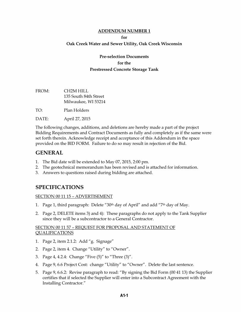
ADDENDUM NUMBER 1 for
Oak Creek Water and Sewer Utility, Oak Creek Wisconsin
Pre-selection Documents for the
Prestressed Concrete Storage Tank
FROM: CH2M HILL 135 South 84th Street Milwaukee, WI 53214
TO: Plan Holders
DATE: April 27, 2015
The following changes, additions, and deletions are hereby made a part of the project Bidding Requirements and Contract Documents as fully and completely as if the same were set forth therein. Acknowledge receipt and acceptance of this Addendum in the space provided on the BID FORM. Failure to do so may result in rejection of the Bid.
GENERAL 1. The Bid date will be extended to May 07, 2015, 2:00 pm. 2. The geotechnical memorandum has been revised and is attached for information. 3. Answers to questions raised during bidding are attached.
SPECIFICATIONS SECTION 00 11 15 – ADVERTISEMENT
1. Page 1, third paragraph: Delete “30th day of April” and add “7th day of May.
2. Page 2, DELETE items 3) and 4): These paragraphs do not apply to the Tank Supplier since they will be a subcontractor to a General Contractor.
SECTION 00 11 57 – REQUEST FOR PROPOSAL AND STATEMENT OF QUALIFICATIONS
1. Page 2, item 2.1.2: Add “g. Signage”
2. Page 2, item 4. Change “Utility” to “Owner”.
3. Page 4, 4.2.4: Change “Five (5)” to “Three (3)”.
4. Page 9, 6.6 Project Cost: change “Utility” to “Owner”. Delete the last sentence.
5. Page 9, 6.6.2: Revise paragraph to read: “By signing the Bid Form (00 41 13) the Supplier certifies that if selected the Supplier will enter into a Subcontract Agreement with the Installing Contractor.”
A1-1

SECTION 00 41 13 – BID FORM
1. Replace Bid Form with attached Bid Form. The only change was in item 8, “2013” was changed to “2015”.
SECTION 33 16 13.15 – PRESTRESSED CONCRETE TANK
1. Replace this specification section with the attached revised specification section.
DRAWINGS DRAWINGS 01-G-12 and 01-G-13
1. These drawings have structural design criteria that apply to the storage tank.
DRAWINGS 05-C-234 and 05-C-235
1. Although site work and earthwork are not included in the scope of work, site grading drawings are provided for information. DRAWINGS 40-SD-231, 40-SD-301 1. Replace these drawings with attached revised drawings. DRAWINGS 40-A-241 1. Add the following Note: “TANK HATCH TO BE INSTALLED ON A CONCRETE
CURB A MINIMUM 4-INCHES ABOVE THE TOP OF THE TANK. TOP OF CONCRETE CURB TO BE HORIZONTALLY LEVEL.”
DETAIL 4027-601 1. Replace with new detail attached. A ball joint has been added.
DETAIL 4027-615 1. Delete this Detail.
End of Addendum 1
A1-2

F:\OAK CREEK WTP 2014\DRAFT GEOTECHNICAL MEMORANDUM- APRIL 24 2015.DOCXF:\OAK CREEK WTP 2014\DRAFT GEOTECHNICAL MEMORANDUM.DOCX
T E C H N I C A L M E M O R A N D U M Subsurface Exploration and Geotechnical Engineering Analyses – 2016 Water Treatment Plant Improvements PREPARED FOR: Oak Creek Water and Sewer Utility
COPY TO: Project Team
PREPARED BY: Charles J. Winter, P.E., Senior Geotechnical Engineer
DATE: April 24, 2015
PROJECT NUMBER: 653463.03.35.30.36
REVISION NO.: Draft ‐ 2
1.0 Project Overview The project involves constructing three structures and related facilities to the north and west of the existing Oak Creek Water Treatment Facility at 9325 South 5th Avenue in Oak Creek, Wisconsin. The three structures consist of:
1. An intermediate pump station (IPS) and ultraviolet radiation (UV) treatment facility. This structure will have a rectangular footprint with approximate plan dimensions of 104 feet by 61 feet. The structure will be positioned 66 feet north of the “Filters 7 to 14” building. The southern approximate 47 feet of the facility will have a deep “wet well” structure. The wet well will have a base slab subgrade of approximate elevation 57.51. The remainder of the structure will have a base slab elevation of either 87 or 96, with frequent undulations in the base slab and perimeter foundations to accommodate required subterraneous piping. The wet well will impart a net stress load to the underlying soils of approximately 3.3 kips per square foot (ksf); the remainder of the facility will be supported on building perimeter foundations imparting a net stress increase between 2.5 to 6 kips per lineal foot (klf) for dead (structure) load and 1.2 klf for snow load. Slab loads are anticipated to be in the range of 100 pounds per square foot (psf). An enclosed walkway will connect the facility south to the existing plant.
2. A 2‐million‐gallon storage tank. The tank will be circular in plan dimension and will be positioned approximately 250 feet north of the Administration and Filtration Facility, on land owned by the city of Oak Creek. The tank will have an inside diameter of 100 feet and have a base slab elevation of 96; this elevation is between 4 to 8 feet above existing ground surface elevation. The tank structure will be supported on a perimeter (ring) foundation with dead load of 5.4 kips per lineal foot and a liquid load of 4.4 kips per lineal foot. The base slab will be relatively thin with thickened edges and will impart a maximum hydraulic load of 35 feet of water (approximate load of 2.2 ksf) directly to the underlying subgrade.
3. A high‐lift pump facility. The facility will be rectangular in plan view, with approximate dimensions of 141 by 58 feet. The structure will be positioned approximately 270 feet north of the Administration and Filtration Facility and will be approximately 15 feet east of the before‐mentioned planned storage tank. The eastern and western thirds of the facility will have a base slab elevation of approximately 89 with the central third with a base slab elevation of 97.
Process piping will be installed to connect the existing facility to the proposed facilities and into the existing distribution system. The proposed piping will have diameters ranging between 24 and 42 inches and will consist of either ductile iron or precast pre‐stressed concrete pipe.
1 Unless noted otherwise all elevations in this report are assumed to be positive, in units of feet and with respect to the project datum (City of Oak Creek Datum).

TECHNICAL MEMO – SUBSURFACE EXPLORATION AND GEOTECHNICAL ENGINEERING ANALYSES – 2016 WATER TREATMENT PLANT IMPROVEMENTS
2 F:\OAK CREEK WTP 2014\DRAFT GEOTECHNICAL MEMORANDUM- APRIL 24 2015.DOCXF:\OAK CREEK WTP 2014\DRAFT GEOTECHNICAL MEMORANDUM.DOCX
Significant earthwork, typically resulting in increasing grades between 2 and 4 feet above existing grade will be performed to facilitate drainage. A storm water pond will be excavated on the northern portion of the property, approximately 100 feet north of the proposed High Lift Pump Station. The base of the pond is at approximate elevation 91 resulting in as much as 6 or 7 feet of excavation below existing grade to facilitate pond construction.
Paved access paths will be constructed to connect the new facilities to both the existing facility and to a new eastern gate on 5th Avenue.
1.1 Existing Site Conditions The project site is divided between two parcels of land; the IPS/UV facility will be positioned on land currently within security perimeter fencing associated with the existing water treatment facility. The parcel is currently grass‐covered and relatively level, with surface elevations ranging between 93 and 96.
The water storage tank and the high‐lift pump facility will be constructed on undeveloped land immediately north of the treatment plant; the land extends from the existing perimeter fence to American Avenue on the north and 5th Avenue on the east. The land has an undulating ground surface, with ground surface elevations ranging between 89 and 99, with the lowest elevations nearest the existing treatment plant, increasing to the north.
The parcel is covered with grass. Anecdotal information from the Client suggests that a tavern once occupied the parcel near the corner of American Avenue and South 5th Avenue. There was also recollection that some fill may have been placed to establish current grades. Small areas of concrete were exposed at the ground surface on the parcel.

TECHNICAL MEMO – SUBSURFACE EXPLORATION AND GEOTECHNICAL ENGINEERING ANALYSES – 2016 WATER TREATMENT PLANT IMPROVEMENTS
F:\OAK CREEK WTP 2014\DRAFT GEOTECHNICAL MEMORANDUM- APRIL 24 2015.DOCXF:\OAK CREEK WTP 2014\DRAFT GEOTECHNICAL MEMORANDUM.DOCX 3
2.0 Exploration Procedures 2.1 Field Exploration Procedures The subsurface exploration program consisted of drilling 12 soil borings. The original subsurface exploration program, executed before finalization of building footprints, consisted of drilling two soil borings (denoted 2014‐1 and 2014‐2) in the area slated for the intermediate pump station / UV treatment facility, two soil borings (2014‐3 and 2014‐4) in the area slated for the storage tank, two borings (2014‐5 and 2014‐6) drilled for the high lift pump facility, and one soil boring (2014‐7) drilled in an area slated for a proposed detention pond. Subsequent to the execution of the borings the footprint for the storage tank and the pond were significantly changed; this necessitated two additional soil borings (2014‐8 for the tank, 2014‐9 for the pond). Two soil borings (2014‐3A and 2014‐4A) were drilled, at the drilling subcontractor’s expense, at borings 2014‐3 and 2014‐4 to obtain information that was inadvertently not collected during the original exploration. Finally one boring (2014‐8PMT) was drilled to facilitate pressuremeter testing in the footprint of the storage tank.
Borings were advanced to depths ranging from 20 to 100 feet, with at least one boring of at least 70 feet drilled in the footprint of each structure. The number of borings and their respective depths were established by CH2M HILL. As‐drilled boring locations are indicated on the Soil Boring Location Diagram attached to this Memoradum.
The drilling was facilitated by Terracon, Inc. of Franklin, Wisconsin (Terracon). Terracon performed drilling coordination, laboratory testing, and pressuremeter testing/data reduction. The drilling was subcontracted by Terracon to J&J Soil Testing Ltd. (J&J) of Richfield, Wisconsin. Borings 2014‐1 through 2014‐7 were staked by the project civil engineer, GRAEF, Inc. of Milwaukee, Wisconsin. The remaining borings were located by the driller using tape‐and‐stake methods referenced to available site features. Ground surface elevations at boring locations were determined based on a topographic survey map supplied by GRAEF, Inc., and are indicated on the boring logs in the attached Terracon Geotechnical Data Report.
The borings were drilled using a CME‐45 drill rig and a two‐person drill crew. J&J logged conditions encountered in the borings. The drilling methods used to advance the borings are noted on the boring logs.
Soil samples were obtained in the borings at 2.5‐foot intervals to either 10 feet or through fill/organic/low strength soils (whichever is deeper), and at 5‐foot intervals thereafter to the boring termination depth in the deeper borings. The samples were obtained in general accordance with ASTM Specification D‐1586. Selected samples were obtained using 3‐inch‐diameter thin‐walled “Shelby” tubes in accordance with ASTM D‐1587.
As each soil sample was brought to the ground surface, the material was preliminarily classified by J&J. Representative portions of the split‐barrel samples were then placed in glass jars. Aluminum foil was then placed at the top of each jar and a cap was used to seal each jar. Upon completion of the field exploration program, all obtained samples were delivered Terracon for further classification and laboratory testing.
During drilling operations, J&J maintained a field log for each boring which described the method(s) of borehole advancement, sample types, sample depths, lengths of sample recoveries, and observations regarding soil and groundwater conditions. These field logs were later used by the geotechnical engineer as an aid in preparing the final boring logs. Final boring logs are contained in the Terracon Geotechnical Data Report attached to this memorandum.
2.2 Laboratory Testing Procedures Each soil sample was visually examined by a Terracon geotechnical engineer, and classified on the basis of texture and plasticity in accordance with the Unified Soil Classification System (USCS). A chart describing this system of classification is included in the Terracon report attached to this memorandum. The two‐letter

TECHNICAL MEMO – SUBSURFACE EXPLORATION AND GEOTECHNICAL ENGINEERING ANALYSES – 2016 WATER TREATMENT PLANT IMPROVEMENTS
4 F:\OAK CREEK WTP 2014\DRAFT GEOTECHNICAL MEMORANDUM- APRIL 24 2015.DOCXF:\OAK CREEK WTP 2014\DRAFT GEOTECHNICAL MEMORANDUM.DOCX
designator following each soil description on the boring log is the group symbol using this method of classification.
Similar soils were grouped into the major zones noted on the boring logs. In some cases, strata contact lines have been estimated. Where strata changes occur between sampled depths, and the driller’s field log does not indicate a strata change depth based on drilling action, the strata change depth is indicated as the midpoint between recovered sample depths. In‐situ, the transition between soil types may not occur at the midpoint between sampled depths, and may be gradual in both the horizontal and vertical directions. For these reasons, for this report narrative, referenced soil‐strata depths and thicknesses should be considered approximate.
The laboratory testing program consisted of performing calibrated penetrometer strength tests, and water content tests on selected cohesive soil samples, unconfined compression tests on 6 samples, Atterberg limit tests on 9 samples, and one‐dimensional consolidation testing on one Shelby tube sample.
The calibrated penetrometer strength test is a method of estimating a cohesive soil's unconfined compressive strength by measuring the soil's resistance to penetration by a small, spring‐calibrated plunger. The water content test is used as a qualitative indicator of the compressibility of the soil.
Photo‐ionization detector (PID) readings were obtained on each sample, with the exception of samples from borings 2014‐3 and 2014‐4 (which was a laboratory oversight, hence requiring drilling borings 2014‐3A and 2014‐4A). PID readings are discussed in Section 3.5.
The laboratory test results are presented on the boring logs Consolidation results and plots of the unconfined compression and Atterberg limit results are provided in the Terracon geotechnical data report attached to this memorandum.

TECHNICAL MEMO – SUBSURFACE EXPLORATION AND GEOTECHNICAL ENGINEERING ANALYSES – 2016 WATER TREATMENT PLANT IMPROVEMENTS
F:\OAK CREEK WTP 2014\DRAFT GEOTECHNICAL MEMORANDUM- APRIL 24 2015.DOCXF:\OAK CREEK WTP 2014\DRAFT GEOTECHNICAL MEMORANDUM.DOCX 5
3.0 Exploration Results 3.1 Previous Explorations Several previous subsurface explorations were performed, at various time periods, in conjunction with construction and subsequent expansion of the existing water treatment plant. There is considerable geotechnical information associated with design of the existing facilities, however the information was not proximate to the proposed structures. No subsurface information was available regarding the undeveloped land to the north of the existing plant.
3.2 Subsurface Conditions The following narrative is a generalization of the subsurface conditions encountered by the borings drilled in the vicinity of the proposed addition areas, with depths approximate, and referenced to existing ground surface. For a more‐detailed description of the subsurface conditions encountered at each boring location, please refer to the boring logs in the attached Terracon Geotechnical Data Report.
3.2.1 Topsoil
Topsoil was encountered at the surface at each boring location. Topsoil thicknesses varied from 2 to 18 inches.
3.2.2 Fill Soils
Fill was encountered in each soil boring. The composition and consistency of the fill was markedly different in borings 2014‐1 and 2014‐2 compared to the rest of the borings.
The fill encountered in borings 2014‐1 and 2014‐2 was comprised predominantly of stiff to hard lean clay. The fill in these two borings extended to a depth of 12 feet (elevation 82.7) in boring 2014‐1 and 14 feet (elevation 79.5) in boring 2014‐2. No organics or man‐made matter were observed in the fill. Water contents ranged from 16 to 23 percent, with full (or near‐full) recoveries on each sample. The homogeneity of this material, the lack of foreign or organic matter, and the SPT and unconfined compressive strength suggest that this material was placed in some kind of engineered manner. This material is suitable for support of lightly loaded foundations and floor slabs.
The fill encountered in the remainder of the borings (borings in the north parcel) also encountered fill, although the fill was considerably more heterogeneous and contained organics and man‐made matter.
The fill in the borings on the north parcel extended the deepest in boring 2014‐7 (where fill extended to elevation 79.5) and precipitously increased to the north and west, with bottom‐of‐fill elevations of 84 to 86 in the borings drilled proximate to the proposed tank (borings 2014‐3/3A, 2014‐4/4A, and 2014‐8/8PMT) and bottom‐of‐fill elevations increasing to 90.5 in the northern‐most boring (2014‐9). The fill generally consisted of lean clay with sporadic occurrences of fat clay. Man‐made materials including asphalt, cinders, and concrete rubble were encountered within the fill. Organic matter, including topsoil and peat were also common within the fill. The man‐made and organic fill components were most‐pronounced in the borings near the proposed tank. The uppermost 3 to 4 feet of clay in most borings had consistencies in the very stiff to hard range (with unconfined compressive strengths of 3 to 4.5 tons per square foot (tsf)). The underlying clay was markedly weaker, with confined compressive strengths ranging between 0.25 and 1.0 tsf. Water contents were also varied, with some borings exhibiting fill with water contents between 15 and 25 percent and other borings, particularly borings 2014‐3 and 2014‐7 encountering water contents ranging as high as 58 to 195 percent. The heterogeneity of the soils, the presence of man‐made matter and the weak nature of the soils indicates that these fill materials were not placed in a controlled and engineered manner; these soils are considered weak and highly compressible; they are not considered suitable for support of foundations or building slabs.

TECHNICAL MEMO – SUBSURFACE EXPLORATION AND GEOTECHNICAL ENGINEERING ANALYSES – 2016 WATER TREATMENT PLANT IMPROVEMENTS
6 F:\OAK CREEK WTP 2014\DRAFT GEOTECHNICAL MEMORANDUM- APRIL 24 2015.DOCXF:\OAK CREEK WTP 2014\DRAFT GEOTECHNICAL MEMORANDUM.DOCX
3.2.3 Organic Soils
Predominantly organic soils, likely native and deposited as an estuarine deposit, were encountered in borings 2014‐3/3A, 2014‐4/4A, 2014‐5, and 2014‐8. These soils were comprised predominantly of organic silts, organic clays, and peats. These soils extended to approximate elevation 80 in borings 2014‐3/3A, 2014‐4/4A, and 2014‐5, and elevation 74 in boring 2014‐8. These soils have very low SPT values (typically 3 blows per foot (bpf) or less) and high water contents ranging from 54 to 132 percent. A consolidation test was performed on a sample of organic material in boring 2014‐5. These organic soils are considered very weak and highly compressible and not suitable for support of foundations or floor slabs in their current condition.
3.2.4 Native Inorganic Soils
Inorganic native soils consisting of lean clay were consistently encountered below the above‐described fill and/or organic materials in every boring. The composition of the clay and the geologic depositional history of the site suggests that these soils are glacial till deposits. These soils typically exhibited consistencies in the very stiff to hard range, with the noticeable exception of soils between elevation 72 and 76.5 in boring 2014‐4, which exhibited a firm consistency2. Water contents were generally between 15 and 25 percent, which is typical for glacial tills of the area. These soils extended to the maximum depth of each boring. Intermittent silt and sand seams were also encountered at‐depth in many borings; such seams are typical of glacial deposits in the area.
3.3 Groundwater Conditions When possible during drilling operations, the driller observed groundwater conditions in the open boreholes. These short‐term observations are summarized in the lower‐left corner of the boring logs.
Groundwater was encountered, while drilling, in six borings (borings 2014‐3/3A, 2014‐4/4A, 2014‐5, and 2014‐8). The depth to groundwater ranged from 9 to 17.5 feet, with corresponding elevations ranging from 76.5 to 84.8. Please note that many borings were drilled using drilling fluid at depths below 15 feet (such borings include 2014‐1 through 2014‐6, sans 2014‐3A and 2014‐4A); the introduction of fluid, while providing for a stable borehole and more‐representative SPT values, obscures observation of groundwater at greater depths and also obscures groundwater information after borehole completion. Furthermore, given the predominance of cohesive soils the occurrence of groundwater may be more indicative of a seam of permeable saturated material and not necessarily indicative of a groundwater table.
In light of the above discussion, the elevation at which groundwater was noted coincides well with the bottom of organic deposits; given the likely estuarine (marsh) deposition of these deposits it is likely that the groundwater table is between 76.5 and 84.5. For purposes of design we have assumed that the groundwater table is approximately 5 feet below existing ground surface. Please note that these elevations are approximate and fluctuations in the groundwater table can and do occur in response to precipitation, evaporation, surface runoff and localized dewatering activities in the area.
Soils with low hydraulic conductivity, such as those encountered in this investigation, generally require longer time intervals in order for groundwater equilibrium to be achieved. If a more accurate determination of the groundwater table is desired, groundwater observation wells could be installed, and groundwater observations may be obtained over an extended time period.
2 Samples 8 and 9 of boring 2014‐4, while exhibiting low compressive strength (as determined by a calibrated penetrometer) had high SPT values (36 and 33 blows per foot), which suggests that this material was highly disturbed when removed from the borehole, which may attribute to the unusually low unconfined compressive strength values.

TECHNICAL MEMO – SUBSURFACE EXPLORATION AND GEOTECHNICAL ENGINEERING ANALYSES – 2016 WATER TREATMENT PLANT IMPROVEMENTS
F:\OAK CREEK WTP 2014\DRAFT GEOTECHNICAL MEMORANDUM- APRIL 24 2015.DOCXF:\OAK CREEK WTP 2014\DRAFT GEOTECHNICAL MEMORANDUM.DOCX 7
3.4 Pressuremeter Test Results A pressuremeter testing program was undertaken to provide in‐situ soil parameters for use in foundation design of the proposed storage tank. The pressuremeter is an in‐situ test device consisting of a cylindrical probe that is inserted into a pre‐drilled borehole, and expanded against the soil on the sides of the borehole. The probe is then incrementally inflated at various pressures. The deformation of probe at the various pressures is recorded and used to estimate the stress‐strain characteristics of the soil.
The pressuremeter tests were performed by Terracon in boring 2014‐8PMT. The depths at which tests were performed were selected based on the proposed elevation of the base slab, and on the soil deposits encountered during sampling in borings 2014‐8.
The results of the pressuremeter tests are presented in Table 1.
TABLE 1 Pressuremeter Test Results Summary
Boring Number
Depth, feet
Po, tsf
Pf, tsf
Pl, tsf
Ed, tsf
E+, tsf
Ed/E+, tsf
2014‐8PMT 18.0‐20.5 1.5 4.6 9.1 80 169 0.47
35.0‐37.5 2.6 8.4 19.2 129 243 0.53
50.0‐52.5 3.0 12.0 27.8 259 464 0.56
78.0‐80.5 4.0 13.0 32.8 233 678 0.34
Average 0.45
The at‐rest pressure, Po, represents the pressure at which the probe has expanded into firm contact with the soil on the sides of the borehole, and the pressure at which the plot of probe volume versus pressure becomes linear. The creep pressure, Pf , represents the pressure at which the plot ceases to be linear (i.e., the pressure at which increasing deformations result from a given incremental pressure increase). The limit pressure, Pl , is the pressure at which complete failure of the soil has occurred (i.e., the plot is vertical). The deformation modulus, Ed, is the slope of the initial linear portion of the plot. The E+ modulus is the slope of the recompression portion of the plot.
The results of the pressuremeter tests are graphically presented in the form of plots of probe volume versus applied pressure in the Terracon geotechnical data report attached to this memorandum.
3.5 Photo-Ionization Detector Readings A Thermo 580B OVM photoionization detector (PID) was used to screen the soil cuttings on jarred samples in the lab immediately prior to classification. The unit was last serviced in October 2014 and was calibrated the same day the monitoring was performed. The instrument is capable of detecting certain volatile organic compounds (VOCs), including many of the volatile components characteristic of petroleum products and common solvents. PID readings are documented on the boring logs in the Terracon geotechnical data report attached to this memorandum.

TECHNICAL MEMO – SUBSURFACE EXPLORATION AND GEOTECHNICAL ENGINEERING ANALYSES – 2016 WATER TREATMENT PLANT IMPROVEMENTS
8 F:\OAK CREEK WTP 2014\DRAFT GEOTECHNICAL MEMORANDUM- APRIL 24 2015.DOCXF:\OAK CREEK WTP 2014\DRAFT GEOTECHNICAL MEMORANDUM.DOCX
4.0 Analyses and Recommendations There are several components to the proposed water plant improvements. They include three structures (described in Section 1.0); each of these structures presents different issues with regard to foundation design and construction. In addition to the structures there is significant underground piping proposed and there is considerable planned earthwork, including a new stormwater detention pond on the north portion of the project site. Each of these elements is discussed below.
4.1 Immediate Pump Station (IPS) / Ultraviolet (UV) Disinfection Building The soils in the vicinity of the footprint of the proposed IPS/UV building consist of between 12 and 14 feet of lean clay fill overlying lean clay glacial till. As described in Section 3.2.2 the fill soils were relatively homogeneous, typically exhibited very stiff consistencies, and did not contain organic or man‐made matter that was typical in fills explored in borings for the other structures. The fill soils are suitable for support of shallow spread foundations (for the portions of the IPS/UV structure with footing subgrade elevations 87 and 95) as well as conventional slabs‐at‐grade. Shallow spread foundations bearing on inorganic soils can be proportioned for a maximum net allowable soil bearing stress of 2,000 pounds per square foot (psf). The net allowable bearing stress refers to the stress transmitted to the soil in excess of the minimum final adjacent overburden stress. We expect soils suitable for the recommended bearing stress to be present at the design foundation elevations.
Exposed subgrade soils should exhibit an unconfined compressive strength of at least 1.0 tsf. We anticipate suitable soils will exist at the proposed subgrade conditions. However, if suitable soil conditions are not encountered at the planned foundation subgrade, then the foundations should extend through the unsuitable soil and bear on the suitable soils below. In any areas where overexcavations are required, it may be desired to support those foundations at the original planned elevation. Overexcavations may be extended to suitable soils and backfilled with cementious low strength material (“CLSM”); CLSM should have sufficient Portland cement and/or fly ash content to achieve a minimum 28‐day unconfined compressive strength in the range of 50 to 150 pounds per square inch (psi). If the overexcavations are backfilled using structural soil fill, the fill should consist of a reasonably well‐graded select granular material containing less than 12 percent by weight passing the No. 200 sieve, and placed and compacted as described in Section 5.2. The overexcavations should extend a minimum of 1‐foot horizontally from each edge of the footing for each foot of fill required below the footing base.
The wet‐well portion of the IPS/UV building, extending to elevation 57.5, will be bearing in very stiff glacial soil. Foundations / mat slabs extending to this elevation can be proportioned for a maximum net allowable soil bearing stress of 4,000 psf. It is suspected that this wet‐well will impart a very low net bearing stress, when the weight of the soil displaced is considered. Soils at this elevation should exhibit an unconfined compressive strength of at least 2 tsf; soils that are disturbed or do not meet the above requirement should be removed and replaced as described above.
We anticipate that the wet‐well portion of the IPS/UV facility will experience relatively little settlement. However the portion of the IPS/UV supported at the higher elevations may exhibit settlement on the order of ¾ to 1 inch; so differential settlements on the order of ¾ inch may be incurred between the wet‐well and adjacent portions of the building. We recommend that the structure be designed with joints to allow for the estimated differential settlement.
The wet well will require deep excavation and an excavation retention system, as discussed in Section 5.5. Regardless of the type of retention system there will be an annulus (void), likely on the order of a couple of feet between the finished wet well walls and the undisturbed adjacent soil. We recommend that this annulus be kept as minimal as practical and the annulus be backfilled with a controlled cementious material (CLSM) with minimum properties described earlier in this section.

TECHNICAL MEMO – SUBSURFACE EXPLORATION AND GEOTECHNICAL ENGINEERING ANALYSES – 2016 WATER TREATMENT PLANT IMPROVEMENTS
F:\OAK CREEK WTP 2014\DRAFT GEOTECHNICAL MEMORANDUM- APRIL 24 2015.DOCXF:\OAK CREEK WTP 2014\DRAFT GEOTECHNICAL MEMORANDUM.DOCX 9
The slab for the IPS/UV building should be able to be supported at grade, provided the subgrade is properly prepared and proofrolled as described in Section 5.1. To provide a uniform floor slab bearing surface, and to provide a barrier against the capillary rise of water, we recommend that a minimum of 6 inches of free‐draining granular material be placed directly below the floor slabs. For this purpose we recommend the use of an angular aggregate meeting the gradation requirements of ASTM Specification C‐33, Coarse Aggregate, Size 67 or an equivalent free‐draining material. In addition, a vapor barrier should be used under slabs on which moisture‐sensitive floor coverings will be used.
At a minimum, the floor slabs should be nominally (mesh) reinforced, and should be constructed independently from foundation‐supported walls and columns to allow for differential movement between these elements. For lightly‐loaded floor slabs, we anticipate settlements on the order of ¼ inch. This estimate assumes proper compaction of engineered fill beneath the floor slabs, and of backfill placed in foundation excavations and utility (pipe) trenches. The walls of the wet well should be designed to resist lateral earth pressure. Since the wet well walls will not be equipped with an exterior drainage layer, the walls should be designed to withstand hydrostatic pressure in addition to soil pressure. Since the structure will not allow the walls to deflect the walls should be designed for an equivalent at rest fluid pressure of 50 psf per foot of depth, above elevation 90 (above the long‐term groundwater table), and 90 psf per foot of depth below elevation 90 (below the groundwater table). The higher value below the groundwater table reflects the added force due to hydrostatic water pressure. A waterproofing membrane should be applied to the exterior surface of the below‐grade structure.
The lateral earth pressure acting on below‐grade walls would be increased by surcharge loads acting on the ground surface adjacent to the wall. To account for typical construction surcharge loads, such as loaded concrete trucks, we recommend that the walls be designed for a uniform lateral pressure of 200 psf within 10 feet of the ground surface, and a uniform lateral pressure of 100 psf for depths between 10 and 20 feet below the ground surface. A waterproofing membrane should be applied to the exterior surface of the below‐grade structure.
In order to limit frost penetration below foundations, we recommend that exterior and perimeter foundations bear at a minimum depth of 4 feet below the lowest final adjacent ground surface. For stability considerations during construction, isolated column and continuous wall foundations should have minimum widths of 30 and 18 inches, respectively.
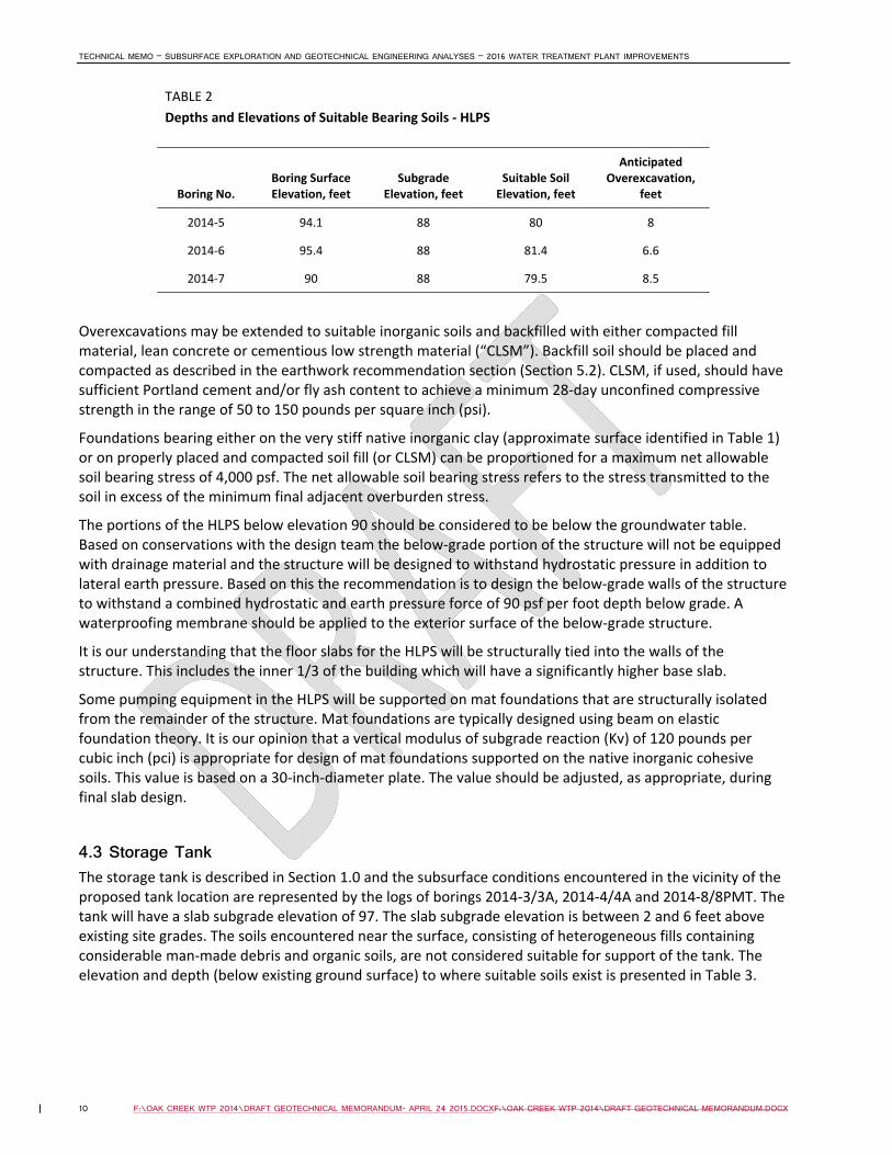
4.2 High-Lift Pump Station The high‐lift pump station (HLPS) will have base slab subgrade elevation of 88 for the approximate eastern and western thirds and will have a subgrade elevation of 96 for the middle third. All foundations for the facility are proposed to bear at elevation 88. Several subterranean pipes will enter and exit the facility.
The soil conditions encountered in borings drilled in proximity to the footprint of the High‐Lift Pump Station (2014‐5 through 2014‐7) encountered 6 to 10.5 feet of various fill materials, and in the case of boring 2014‐5, encountered an additional 6.5 feet of highly organic matter underneath the fill. The fill and organic matter encountered in these borings is unacceptable for support of building foundations, building slabs, or pumps and other machinery. For this reason we recommend that all fill, organic materials, and soft to stiff inorganic clays be removed from the entire building footprint. This will require between 6.6 and 8.5 feet of overexcavation, as detailed in Table 2.
TECHNICAL MEMO – SUBSURFACE EXPLORATION AND GEOTECHNICAL ENGINEERING ANALYSES – 2016 WATER TREATMENT PLANT IMPROVEMENTS
10 F:\OAK CREEK WTP 2014\DRAFT GEOTECHNICAL MEMORANDUM- APRIL 24 2015.DOCXF:\OAK CREEK WTP 2014\DRAFT GEOTECHNICAL MEMORANDUM.DOCX
TABLE 2
Depths and Elevations of Suitable Bearing Soils ‐ HLPS
Boring No. Boring Surface Elevation, feet
Subgrade Elevation, feet
Suitable Soil Elevation, feet
Anticipated Overexcavation,
feet
2014‐5 94.1 88 80 8
2014‐6 95.4 88 81.4 6.6
2014‐7 90 88 79.5 8.5
Overexcavations may be extended to suitable inorganic soils and backfilled with either compacted fill material, lean concrete or cementious low strength material (“CLSM”). Backfill soil should be placed and compacted as described in the earthwork recommendation section (Section 5.2). CLSM, if used, should have sufficient Portland cement and/or fly ash content to achieve a minimum 28‐day unconfined compressive strength in the range of 50 to 150 pounds per square inch (psi).
Foundations bearing either on the very stiff native inorganic clay (approximate surface identified in Table 1) or on properly placed and compacted soil fill (or CLSM) can be proportioned for a maximum net allowable soil bearing stress of 4,000 psf. The net allowable soil bearing stress refers to the stress transmitted to the soil in excess of the minimum final adjacent overburden stress.
The portions of the HLPS below elevation 90 should be considered to be below the groundwater table. Based on conservations with the design team the below‐grade portion of the structure will not be equipped with drainage material and the structure will be designed to withstand hydrostatic pressure in addition to lateral earth pressure. Based on this the recommendation is to design the below‐grade walls of the structure to withstand a combined hydrostatic and earth pressure force of 90 psf per foot depth below grade. A waterproofing membrane should be applied to the exterior surface of the below‐grade structure.
It is our understanding that the floor slabs for the HLPS will be structurally tied into the walls of the structure. This includes the inner 1/3 of the building which will have a significantly higher base slab.
Some pumping equipment in the HLPS will be supported on mat foundations that are structurally isolated from the remainder of the structure. Mat foundations are typically designed using beam on elastic foundation theory. It is our opinion that a vertical modulus of subgrade reaction (Kv) of 120 pounds per cubic inch (pci) is appropriate for design of mat foundations supported on the native inorganic cohesive soils. This value is based on a 30‐inch‐diameter plate. The value should be adjusted, as appropriate, during final slab design.
4.3 Storage Tank The storage tank is described in Section 1.0 and the subsurface conditions encountered in the vicinity of the proposed tank location are represented by the logs of borings 2014‐3/3A, 2014‐4/4A and 2014‐8/8PMT. The tank will have a slab subgrade elevation of 97. The slab subgrade elevation is between 2 and 6 feet above existing site grades. The soils encountered near the surface, consisting of heterogeneous fills containing considerable man‐made debris and organic soils, are not considered suitable for support of the tank. The elevation and depth (below existing ground surface) to where suitable soils exist is presented in Table 3.

TECHNICAL MEMO – SUBSURFACE EXPLORATION AND GEOTECHNICAL ENGINEERING ANALYSES – 2016 WATER TREATMENT PLANT IMPROVEMENTS
F:\OAK CREEK WTP 2014\DRAFT GEOTECHNICAL MEMORANDUM- APRIL 24 2015.DOCXF:\OAK CREEK WTP 2014\DRAFT GEOTECHNICAL MEMORANDUM.DOCX 11
TABLE 3
Depths and Elevations of Suitable Bearing Soils – Water Storage Tank
Boring No. Boring Surface Elevation, feet
Subgrade Elevation, feet
Suitable Soil Elevation, feet
Total Fill Under Slab, feet
Overexcavation, feet
2014‐3 93.8 97 80 17 13.8
2014‐3A 93.8 97 80.5 16.5 13.3
2014‐4 95 97 80 17 15
2014‐4A 95 97 84 13 11
2014‐8 91.5 97 74 23 17.5
There are two options for support of the tank. The first option is to remove the unsuitable soils under the entire tank footprint. The magnitude of overexcavation is indicated in the last column of Table 3. The soils will need to be replaced with fill placed and compacted as described in Section 5.2. This will result in between 13 and 23 feet of newly placed fill between the tank slab and the underlying native inorganic glacial till soils. Anticipated settlements under this scenario are provided in Table 4.
TABLE 4 Anticipated Settlement of Tank Assuming Poor Soils Removed and Replaced with Suitable Fill
A Assumes engineered fill placed in maximum 8‐inch‐thick lifts and compacted to equivalent dry density equal to 95% of that obtained on representative sample of material tested to modified Proctor specifications (ASTM D‐1557).
The values in Table 4 were derived using finite‐element modeling using the PLAXIS software, and modeling the native cohesive till soils with moduli obtained through pressuremeter testing (Section 3.4). Compressibility of properly placed and compacted inorganic fill was estimated by reviewing research done on the topic3.
If settlement magnitudes provided in Table 4 are unacceptable we recommend a deep foundation solution. As of issuance of this report the above settlements are considered tolerable to a typical tank foundation described above; therefore no deep foundation solution is envisioned. It is important that all piping connecting to the tank be equipped to tolerate settlement magnitudes identified in Table 4.
Similar to the other structures, the perimeter foundation for the tank should extend a minimum of 4 feet below adjacent ground surface to minimize impacts due to frost on the performance of the facility.
The ring foundation may be proportioned for a net allowable bearing stress of 3.0 ksf. The net allowable soil bearing stress refers to the stress transmitted to the soil in excess of the minimum final adjacent overburden stress.
3 “Soil Compaction Specification Procedure for Desired Field Strength Response”, produced by the Joint Highway Research Project (Purdue University, West Lafayette, IN) for the Federal Highway Administration (Report No. JHRP‐78‐7), June 1978.
Long‐Term Settlement of Engineered Fill, inchesA
Long‐Term Settlement of Native Soils, inchesA Total Estimated Settlement, inchesA
Center Edge Differential Center Edge Differential Center Edge Differential
1.0 1.0 0.0 4.7 2.8 1.9 5.7 3.8 1.9

TECHNICAL MEMO – SUBSURFACE EXPLORATION AND GEOTECHNICAL ENGINEERING ANALYSES – 2016 WATER TREATMENT PLANT IMPROVEMENTS
12 F:\OAK CREEK WTP 2014\DRAFT GEOTECHNICAL MEMORANDUM- APRIL 24 2015.DOCXF:\OAK CREEK WTP 2014\DRAFT GEOTECHNICAL MEMORANDUM.DOCX
4.4 Yard Piping There will be many pipes connecting the existing plant to the proposed structures, and the proposed structures to the external distribution system. These lines will range in diameter between 24 and 42 inches and will consist of either ductile iron pipe (DIP) or precast pre‐stressed concrete pipe (PCCP). The lines connecting between the existing filtration building and the IPS/UV building will have invert elevations between 62 and 63. Lines connecting the IPS/UV station and the tank and HLS will have invert elevations ranging from 78 to 90. Based on the subsurface information provided, we anticipate that piping extending into the lot north of the existing facility (i.e., piping connecting to the tank and HLPS, and between the tank/HLPS and external distribution lines) will run through areas containing soft organic soil. If encountered at the base of the excavation for these lines, these materials should be removed. In the case of organics extending deeper than two feet below invert the overexcavation can be stopped, a geotextile placed on the exposed (existing fill) subgrade, and backfilled with breaker run material, as described in Section 5.1.
4.5 Detention Pond Low‐permeability clayey soils were encountered in Boring 2014‐9, drilled in the footprint of the proposed retention/detention pond. These soils likely have hydraulic conductivities on the order of 1 x 10‐6 to 1 x 10‐5 cm/sec. For long‐term maintenance considerations, we recommend that the pond have a maximum side slope of 1 vertical to 2.5 horizontal.
4.6 Seismic Design Recommendations The soils encountered at this site are considered “Site Class D” soils as defined in the Wisconsin Administrative Code Comm 62.1615 and the International Building Code Section 1615.1.
4.7 Environmental Issues As detailed in Section 3.2.2 there was man‐made debris encountered in many samples within the fill zone in the borings drilled on the north parcel. Additionally, PID readings (described in Section 3.5 and contained in the boring logs in the attached Terracon report) registered values above background levels. These test results may or may not be indicative of environmentally impacted soils. Any analyses or guidance regarding the PID values obtained or the character of the fill documented during the subsurface exploration in an environmental context is beyond our scope of the services. We advise the Oak Creek Water and Sewer Utility to consult with environmental professionals to assess the existence and/or extent of environmental issues at the site prior to construction. The result of such analyses may affect the recommendations presented in this report; CH2M HILL requests to kept appraised of the outcome of environmental analyses and given the opportunity to reassess the recommendations contained herein.

TECHNICAL MEMO – SUBSURFACE EXPLORATION AND GEOTECHNICAL ENGINEERING ANALYSES – 2016 WATER TREATMENT PLANT IMPROVEMENTS
F:\OAK CREEK WTP 2014\DRAFT GEOTECHNICAL MEMORANDUM- APRIL 24 2015.DOCXF:\OAK CREEK WTP 2014\DRAFT GEOTECHNICAL MEMORANDUM.DOCX 13
5.0 Construction Recommendations The following sections detail construction recommendations pertinent to soil and earthwork‐related aspects of the project.
5.1 Site Preparation and Proofrolling All surficial topsoil, surface vegetation, organic matter, and debris should be removed from the areas slated for earthwork and/or structures. Snow, ice, and frozen subgrades should also be removed immediately prior to fill placement or foundation construction.
Once the stripping operations are completed, the exposed subgrades should be proofrolled. Proofrolling consists of closely spaced passages of the subgrade by a heavily loaded vehicle which is supported on pneumatic tires, such as a tandem axle dump‐truck. The proofrolling operation should be performed under the observation of a geotechnical engineer or an experienced technician.
Subgrade areas either consisting of organic soils or exhibiting excessive rutting‐ or pumping‐type deflections (¾‐inch or greater) during proofrolling should be undercut to firm soils, or to a depth of 30 inches beneath the subgrade, whichever is less. The exception to this is the areas of the proposed tank and HLPS facilities, which require deep overexcavations. If yielding soils remain at the base of the overexcavation, the subgrade should be stabilized by the placement of a geosynthetic fabric, and backfilled to the subgrade elevation with breaker run aggregate, such as described in Table 4 below.
TABLE 4 Gradation Recommendations for Breaker Run Aggregate
Sieve Size Dry Weight Passing, Percent
4 inch 100
2 inch 75 to 95
No. 4 35 to 70
No. 40 15 to 40
No. 100 10 to 25
No. 200 5 to 15
The breaker run should be properly placed and compacted as described in the Earthwork Recommendations in Section 5.1. The geofabric should meet the requirements of Wisconsin Department of Transportation Type SAS (WisDOT Standard Specification 645.2.2), as presented in Table 5.
TABLE 5 Recommended Minimum Geotextile Specifications
Design Parameter Minimum Required Value
Grab Strength (ASTM D4632) 170 pounds
Puncture Strength (ASTM D4833) 70 pounds
Burst Strength (ASTM D3786) 210 psi
Permitivity (ASTM D4491) 0.35 seconds‐1
Apparent Opening Size (AOS) (ASTM D4751) 70

TECHNICAL MEMO – SUBSURFACE EXPLORATION AND GEOTECHNICAL ENGINEERING ANALYSES – 2016 WATER TREATMENT PLANT IMPROVEMENTS
14 F:\OAK CREEK WTP 2014\DRAFT GEOTECHNICAL MEMORANDUM- APRIL 24 2015.DOCXF:\OAK CREEK WTP 2014\DRAFT GEOTECHNICAL MEMORANDUM.DOCX
The geofabric should be installed in accordance to the manufacturer’s specifications. All seams should be overlapped a minimum of 2 feet, or greater if specified by the manufacturer.
Structural fill should consist of inorganic soil placed and compacted as specified in Section 5.1. The structural fill should be placed a minimum of five feet beyond all edges of the building and roadway areas, and an additional foot for each vertical foot of fill to be placed. This is to provide adequate lateral confinement of the structural fill.
The inorganic soils encountered at the site are generally suitable for use as structural fill. However, clayey soils are sensitive to the moisture content at which they are compacted. Moisture conditioning should be performed as described in Section 5.1. Based on the results of the laboratory moisture content tests and our experience with similar soils, it appears that the moisture contents of the near‐surface inorganic soils are likely above their optimum moisture content, and will require drying before they can be compacted to an adequate degree. Drying can be difficult to achieve during cool, wet times of the year.
We recommend that a geotechnical engineer, or an experienced technician, be present during filling or other earthwork operations. This is to confirm that only approved backfill materials are used, as well as to confirm that the soils have achieved adequate density requirements. This will also allow for observation to document that the existing subgrade is undisturbed, suitable for placement of fill or concrete, and to confirm that the site is prepared according to the intent of this report.
5.2 Earthwork Recommendations Fill or backfill placed in this project should consist of inorganic soil which contains no debris, stones larger than 4 inches in diameter, nor frozen matter.
The natural water content of the soil should be within three percent of the optimum water content as determined by a Proctor test. If the moisture content of the fill is outside this range, it may be difficult to obtain the specified degree of compaction.
Uniform fill or backfill should be used on the project. If non‐uniform soils are used, or two or more soil types are mixed, the field personnel will have to exercise judgment regarding which Proctor density standard applies. This will reduce the degree of certainty in the test results.
The fill or backfill should be placed in loose horizontal lifts, no thicker than eight inches, and compacted with a compactor appropriate for the soil type. Typically, vibratory drum or vibratory plate compactors are appropriate for the soil type. Typically, vibratory drum or vibratory plate compactors are appropriate for granular soils, while a sheepsfoot, segmented foot, jumping jack, or other compactor which kneads the soil, is appropriate for cohesive soils.
Fill or backfill placed to support floor slabs, foundations, and pavements subject to truck traffic should be compacted to a minimum of 95% of the modified Proctor test (ASTM D1557) density. Fill or backfill placed to in areas not supporting pavements or structures should be compacted to a minimum of 90% of the modified Proctor test density.
In some instances, a relatively thin stratum of weak or unsuitable soil may exist beneath a proposed foundation. It is a common practice to remove a volume of the weak soil for the full thickness of the stratum, and replace it with compacted fill to support the foundation. The weak soil commonly remains in place laterally beyond each excavated and backfilled zone. In this situation, the compacted backfill should extend laterally beyond each edge of the foundation a minimum of ¾ foot for each foot of compacted fil thickness beneath the foundation.
5.3 Drainage and Dewatering Positive drainage to properly maintained ditches, culverts, and channels should be maintained to control surface water from entering the embankment, subgrade, and excavations. Water accumulating in

TECHNICAL MEMO – SUBSURFACE EXPLORATION AND GEOTECHNICAL ENGINEERING ANALYSES – 2016 WATER TREATMENT PLANT IMPROVEMENTS
F:\OAK CREEK WTP 2014\DRAFT GEOTECHNICAL MEMORANDUM- APRIL 24 2015.DOCXF:\OAK CREEK WTP 2014\DRAFT GEOTECHNICAL MEMORANDUM.DOCX 15
excavations and other work areas should be removed promptly. Appropriate sediment control devices (such as silt fences) should be placed at the start of construction and periodically maintained to minimize movement of eroded soil. All ditches, slopes, and other areas susceptible to erosion and disturbed by construction activities should be protected with erosion control devices as early as possible. Erosion checks and/or riprap may be used for erosion control and should be used in areas where high flow rates are anticipated.
Although excavations to proposed subgrade elevations may intercept the groundwater table, we anticipate that inflows and perched water that may be encountered can be handled by typical trench, sump pit and pumping techniques. Subgrade exposure time to water should be minimized. If it is not possible to efficiently remove water from the subgrade a concrete “mud mat” should be placed on a suitable subgrade for protection.
5.4 Subgrade Observation We recommend that all earthwork and foundation subgrades be observed and tested by an experienced geotechnical engineer or a qualified soils technician to determine if the soil and groundwater conditions encountered are consistent with those anticipated in this report. Foundation subgrades should be tested to check for adequate bearing conditions. Subgrades for slabs and new structural fills should be tested for conformance to specified requirements.
In determining suitable foundation subgrades, care should be given to ensure that the soils are suitable for support of the loads for which the structures have been designed. Inorganic cohesive soils that are proportioned for a net allowable soil bearing stress of 2,000 psf should have a minimum unconfined compressive strength of 1.0 ton per square foot (tsf). Inorganic cohesive soils that are proportioned for a net allowable soil bearing stress of 3,000 psf should have a minimum unconfined compressive strength of 1.5 tsf. Granular soils should have an equivalent standard penetration (SPT) value of 15 blows per foot to support 3,000 psf. Native inorganic soils that are proportioned for a net allowable soil bearing stress of 4,000 psf should have a minimum unconfined compressive strength of 2.0 tsf.
5.5 Excavation Issues Considerable vertical excavation will be required to achieve the plan subgrade elevations for the wet well (IPS), and in the case of the HLPS and storage tanks, to achieve desired subgrade soils. In the case of the wet well (and depending on the construction sequencing for the tank and HLPS overexcavations), insufficient room may be available to adequately slope the excavation, hence requiring temporary excavation retention. Temporary shoring will be required in these instances; such systems are typically designed by the contractor. Temporary shoring systems should be designed by an experienced licensed geotechnical or structural engineer.
The Owner and Contractor should make themselves aware of, and become familiar with, applicable local, state, and federal safety regulations, including the current OSHA Excavation and Trench Safety Standards. Construction‐site safety generally is the responsibility of the Contractor, who should also solely be responsible for the means, methods, and sequencing of construction operations. We are providing this information solely as a service to our client. Under no circumstances should the information provided below be interpreted to mean that CH2M HILL assumes responsibility for construction‐site safety or the Contractor's activities; such responsibility is not being implied and should not be inferred.
The Contractor should be aware that slope height, slope inclination, or excavation depths should in no case exceed those specified in local, state, or federal safety regulations, (e.g. OSHA Health and Safety Standards for Excavations, 29 CFR Part 1926), or successor regulations. Such regulations are strictly enforced, and if they are not followed, the Owner, Contractor, and/or earthwork Subcontractor(s) could be liable for

TECHNICAL MEMO – SUBSURFACE EXPLORATION AND GEOTECHNICAL ENGINEERING ANALYSES – 2016 WATER TREATMENT PLANT IMPROVEMENTS
16 F:\OAK CREEK WTP 2014\DRAFT GEOTECHNICAL MEMORANDUM- APRIL 24 2015.DOCXF:\OAK CREEK WTP 2014\DRAFT GEOTECHNICAL MEMORANDUM.DOCX
substantial penalties. The overburden soils encountered by the exploratory borings through which the excavations will extend consisted of fill and natural cohesive soils. We anticipate that the existing site fill soils, and underlying organic and granular soils can be considered Type C soils when applying the OSHA regulations. The underlying native cohesive glacial soils can be considered Type B soils. OSHA requires a maximum slope inclination of 1.0 horizontal to 1.0 vertical for Type B soils, and 1.5 horizontal to 1 vertical for Type C soils. Site soils should be properly dewatered prior to excavation.
Material stockpiles or heavy equipment should not be place within a zone extend at a 1 horizontal to 1 vertical slope from the bottom of the excavation.

TECHNICAL MEMO – SUBSURFACE EXPLORATION AND GEOTECHNICAL ENGINEERING ANALYSES – 2016 WATER TREATMENT PLANT IMPROVEMENTS
F:\OAK CREEK WTP 2014\DRAFT GEOTECHNICAL MEMORANDUM- APRIL 24 2015.DOCXF:\OAK CREEK WTP 2014\DRAFT GEOTECHNICAL MEMORANDUM.DOCX 17
6.0 Limitations This geotechnical exploration and foundation evaluation memorandum was prepared for the Oak Creek Water and Sewer Utility for the specific project and use discussed herein. The specific project details are unique relative to their location, size, configuration, and elevations. The project plans and specifications should be coordinated with the author of this technical memorandum for review to verify that the conclusions and recommendations have been interpreted correctly. Where specific information was not available, assumptions have been made, and are noted as such. These assumptions should be reviewed by the project team to confirm that they are correct for the planned use and project. If these assumptions are not correct, the author of this technical memorandum should be informed and allowed to modify the memorandum, its conclusions, and recommendations. The accuracy and completeness of any documents or information provided by others as to project specifics or prior property uses have been reasonably relied on by CH2M HILL in providing its evaluation. In addition, if details of the project or planned construction sequencing change from that outlined in this report, the author of this report should be notified to determine if the changes affect the recommendations.
The analyses, conclusions, and recommendations in this memorandum are based on the subsurface conditions present in the borings and the engineering characteristics of the soil as determined through field and laboratory testing at this point in time, as defined in the current work scope. Subsurface conditions can change over time due to both natural and man‐made forces, including changes in condition and/or use of adjacent properties.
The memorandum does not reflect variations in subsurface conditions that may exist between or beyond these borings. Variations in soil conditions should be expected between the borings, the nature and extent of which may not become evident until construction is undertaken. The construction should be monitored by the geotechnical engineer or a designated representative to determine if the subsurface conditions are as indicated in the borings.
If the conditions encountered during construction are different from those inferred by the soil borings or the project details, the author of this memorandum must be contacted to determine if modification to the recommendations presented in this report are required. The recommendations found in this report are related and are not mutually exclusive of each other. Therefore, no single portion of the report should be removed or be considered as a stand‐alone recommendation.
The geotechnical engineering recommendations presented herein are an evaluation of subsoil performance based on the geotechnical engineer’s experience and professional opinion. These services were performed with the degree of skill and care normally utilized by other members of the geotechnical engineering profession practicing in this location and at this time. No warranty is either expressed or implied.

88
89
89
89
89
89
89
89
91
91
91
91
91
91
91
91
9191
91
91
92
92
92
92
92
92
92
9292
92
92
92
92
92
92
92
92
92
92
92
92
92
93
93
93
93
93
93
93
93
93
93
93
93
93
93
93
93
93
93
93
93
93
93
93
93
93
93
94
94
94
94
94
94
94
94
94
94
94
94
94
94
94
94
94
94
94
94
94
94
94
94
94
94
96
96
96
96
96
96
96
96
96
96
96
96
96
96
96
96
96
96
96
96
96
97
97
97
97
97
97
97
97
97
97
97
97
97
97
98
98
98
98
98
98
98
98
98
98
98 9
8
98
98
98
99
99
99
99
99
99
99
99
99
101
101
e bit
agg sh
backsight
BM.
BM.
1st fl
backsight
backsight
backsight
BM.
1st fl
1st fl
1st fl
c/l
c/l
c/l
c/l
c/l
c/l
c/l
c/lc/lc/l
c/lc/lc/lc/lc/l
c/lc/lc/lc/l
c/l
c/l
c/l
c/lc/l
c/l
c/l
backsightbacksight
BM.
c/l
c/l
c/l
c/l
backsightbacksight
BM.
backsight
backsight
backsight
backsightbacksight
R BAR
R BAR
R BAR
R BAR
1445
1272
(PE
R
PL
AN)
(PER PLAN)
(PE
R
PL
AN)
(PE
R
PL
AN)
(PER PLAN)(PER PLAN)
(PER PLAN)
(PER PLAN)
(PER PLAN)
(PER PLAN)
(PER PLAN)
(PER PLAN)
(PER PLAN)
(PE
R
PL
AN)
(PE
R
PL
AN)
(PE
R
PL
AN)
(PER PLAN)
(PER PLAN)
(PER PLAN)
(PE
R
PL
AN)
(PE
R
PL
AN)
(PER PL
AN)
(PER PL
AN)
(PER PL
AN)
(PER PL
AN)
(PER PLAN)
(PER PLAN)
(PER PLAN)
(PER PLAN)
(PER PLAN)
(PER PLAN)
(PER PLAN)
(PER PLAN)
(PER PLAN)
(PER PLAN)
(PER PL
AN)
(PE
R
PL
AN)
(PE
R
PL
AN)
(PE
R
PL
AN)
(PER PLAN)
(PER PLAN)
(PER PLAN)
(PER PLAN)
(PER PLAN)
(PER PLAN)
(PER PLAN)
(PER PLAN)
(PER PLAN)
(PER PLAN)
(PER PLAN)
(PER PLAN)
(PER PLAN)
(PER PLAN)
(PER PLAN)
(PER PLAN)
(PER PLAN)
(PE
R
PL
AN)
(PER PLAN) (PER PLAN) (PER PLAN)
(PER PLAN)
(PER PL
AN)
(PER PLAN)
(PER PLAN)
(PE
R
PL
AN)
(PE
R
PL
AN)
(PER PL
AN)
(PER PLAN)
(PER PLAN)
(PE
R
PL
AN)
(PE
R
PL
AN)
(PE
R
PL
AN)
(PE
R
PL
AN)
(PE
R PL
AN)
(PE
R
PL
AN)
(PE
R
PL
AN)
(PER PLAN)
(PER PLAN)
(PER PLAN)
(PE
R
PL
AN)
(PE
R
PL
AN)
(PE
R
PL
AN)
(PE
R
PL
AN)
(PE
R
PL
AN)
(PE
R
PL
AN)
(PER PLAN)
(PE
R
PL
AN)
(PER PL
AN)
PLAN)
(PER
(PE
R PL
AN)
(PE
R
PL
AN)
(PER PLAN)
(PER PLAN)
(PE
R
PL
AN)
(PE
R
PL
AN)
(PER PLAN)
(PE
R
PL
AN)
(PER PLAN)
(PER PLAN)
(PER PLAN)
(PER PLAN)(PER PLAN)
(PE
R
PL
AN)
(PE
R
PL
AN)
(PE
R
PL
AN)
(PER PLAN)(PER PLAN)
(PER PLAN)
(PE
R
PL
AN)
(PER PLAN)
(PER PLAN)
(PE
R P
LA
N)
(PER PL
AN)
(PER PLAN)(PER PLAN)
(PER PLAN)
(PER PLAN)(PER PLAN)
(PE
R
PL
AN)
(PER PL
AN)
(PE
R
PL
AN)
(PE
R
PL
AN)
(PER PLAN)(PER PLAN)
(PER PLAN)(PER PLAN)
(PER PLAN)
(PER PLAN)
(PE
R
PL
AN)
(PER PLAN)
RW
RW
RW
RW
RW
RW
RW
RW
(PE
R
PL
AN)
(PE
R
PL
AN)
(PER PLAN)
(PE
R
PL
AN)
(PE
R
PL
AN)
(PER PLAN)
(PE
R
PL
AN)
(PER PLAN)
PL
AN)
(PE
R
90
90
90
90
90
90
90
90
95
95
95
95
95
95
95
95
95
95
95
95
95
95
95
95
95
95
95
95
95
95
95
95
95
95
95
95
95
95
100
100
100
100
WV
GUY
17
15
19
8
22
12
GRD
GRD
GRD
GRD
GRD
14
14
7
6
5
4
3
3
26
18
6
5
20
20
16
WV
GUY
GUY
WVWV
WV
WV
5
5
GUY
GUY
WV
WV
WV
VENT
?
?
?
?
??
?
?
?
?
?
?
?
?
?
?
05-C-410_653463.dgn
CIVIL
1"=30'
05-C-410
2014-5
2014-8
2014-72014-6
2014-9
2014-3
2014-3A
2014-22014-1
SOIL B
ORIN
G L
OC
ATIO
N P
LA
N
DA KIE
RZ
EK
CJ W
INT
ER
0 30 60 90
Scale In Feet
SOIL BORING LOCATION PLAN N
2014-X
LEGEND
(CURRENT EXPLORATION)
SOIL BORING LOCATION
STORAGE TANK
PUMP STATION
HIGH LIFT
PUMP STATION / UV
INTERMEDIATE
WALKWAY
SOUTH 5TH AVENUE
EA
ST A
ME
RIC
AN A
VE
NU
E
2014-4
2014-4A
FILENAME: PLOT DATE: PLOT TIME:3/5/2015 10:35:53 AM
CH
2M HIL
L 2
015. A
LL RIG
HTS R
ES
ER
VE
D.
THIS D
OC
UM
EN
T,
AN
D T
HE I
DE
AS A
ND D
ESIG
NS I
NC
OR
PO
RA
TE
D H
ER
EIN,
AS A
N I
NS
TR
UM
EN
T O
F P
RO
FE
SSIO
NA
L S
ER
VIC
E, IS T
HE P
RO
PE
RT
Y O
FR
EU
SE O
F D
OC
UM
EN
TS:
1 2 3 4 5 6
B
C
D
VERIFY SCALE
BAR IS ONE INCH ON
ORIGINAL DRAWING.
1"0
c
PROJ
DATE
DA
TE
NO.
DS
GN
DR
RE
VISIO
N
CH
K
AP
VD
BY
AP
VD
SHEET
DWG
A
of
CH
2M HIL
L A
ND IS N
OT T
O B
E U
SE
D, IN W
HO
LE O
R I
N P
AR
T, F
OR A
NY O
TH
ER P
ROJE
CT W
ITH
OU
T T
HE W
RIT
TE
N A
UT
HO
RIZ
ATIO
N O
F C
H2
M HIL
L.
CIT
Y O
F O
AK C
RE
EK,
WIS
CO
NSIN
653463
IMP
RO
VE
ME
NTS
OA
K C
RE
EK W
AT
ER A
ND S
EW
ER U
TILIT
Y
2016 W
AT
ER T
RE
AT
ME
NT P
LA
NT
MARCH 2015

Terracon Consultants, Inc. 204 Moravian Valley Road, Suite G Waunakee, WI 53597 P [608] 849 4998 F [414] 209 7630 terracon.com
March 5, 2015 Mr. Charles Winter CH2M HILL 9575 W. Higgins Road, Suite 700 Rosemont, IL 60018 Re: Geotechnical Engineering Data Report Prepared for Charles Winter on behalf of Ron Pritzlaff
Oak Creek Water Utility Development 170 West Drexel Avenue Oak Creek, WI 53154
Terracon Project No. MR145146 Dear Mr. Winter: Terracon Consultants, Inc. (Terracon) is pleased to present this geotechnical engineering data report for the above referenced project. The attached report includes an overview of the field exploration and laboratory testing methods, as well as final electronic boring logs, laboratory test results, and pressuremeter test results. We appreciate the opportunity to be of service to you. Please feel free to contact us at your convenience with any questions. Sincerely, TERRACON CONSULTANTS, INC. Damien E. Hesse, E.I.T. Paul A. Tarvin, P.E. Staff Geotechnical Engineer Geotechnical Services Manager

Geotechnical Engineering Report Oak Creek Water Utility ■ Oak Creek, Wisconsin March 5, 2015 ■ Terracon Project No. MR145146
Responsive ■ Resourceful ■ Reliable 1
PROJECT OVERVIEW The proposed project details are summarized in the following table:
Location 9325 South 5th Avenue Oak Creek, WI 53154
Existing improvements
The Oak Creek Water and Sewer Utility facilities.
Proposed construction
A new intermediate pump station with a base slab elevation approximately 25 to 30 feet below existing grade.
A new UV facility with base slab at approximately the existing grade.
A new water storage tank with base slab elevation at approximately the existing grade. A rectangular design is expected to have plan dimensions approximately 100 feet by 150 feet and water height approximately 20 feet above existing grades. A circular design is expected to have a diameter of approximately 70 feet and water to a height of 30 feet above existing grades.
A new high lift pump station with base slab at approximately the existing grades.
Grading and Excavation
According to information provided by CH2M HILL up to 30 feet of excavation could be possible for the new intermediate pump station. Other site grading is anticipated to be less than 5 feet.
Below grade areas The new intermediate pump station will be 25 to 30 feet below existing grades.
FIELD EXPLORATION PROCEDURES The boring locations were selected by and located in the field by CH2M HILL. Some of the borings were relocated prior to the first mobilization by Charles Winter. Ground surface elevations were determined in the field by the driller using rod and level techniques and referenced existing building and local street features. The elevations were converted to the Oak Creek City Datum by Charles Winter of CH2M Hill and provided to Terracon for inclusion on the boring logs. The locations and elevations of the borings should be considered accurate only to the degree implied by the means and methods used to define them. The borings were drilled with a truck-mounted, rotary drill rig using continuous flight hollow-stemmed augers and mud rotary methods to advance the boreholes. Hollow-stemmed augers were used for borings B-2014-3A, B-2014-4A, B-2014-7, B-2014-8, and B-2014-9. Mud rotary

Geotechnical Engineering Report Oak Creek Water Utility ■ Oak Creek, Wisconsin March 5, 2015 ■ Terracon Project No. MR145146
methods were used for the remaining borings with Hollow stems used as casing ranging from 5 to 15 feet below ground surface. The originally planned borings (B-2014-1 to B-2014-9) were extended to depths of 50 to 100 feet. Please note that that all soil samples were to be preliminarily screened with a photo-ionization detector (PID); however, the PID screening was inadvertently not completed for borings B-2014-3 and B-2014-4. In discussions with CH2M Hill, we agreed to redrill these two borings to a depth of 20 feet each, and screen those samples with the PID. These borings are identified as B-2014-3A and B-2014-4A. In addition, after review by CH2M Hill of our preliminary test results, they requested that we complete an additional boring so the pressuremeter testing could be completed at select depth intervals. This boring, B-2014-8PMT, was blind drilled to the pressuremeter test depth intervals using rotary wash boring techniques, sampled, and pressuremeter tests performed. Disturbed soil samples were generally obtained using split-barrel sampling procedures in general accordance with ASTM D 1586, in which a standard 2-inch (outside diameter) split-barrel sampling spoon is driven into the ground with a 140-pound safety hammer falling a distance of 30 inches. The number of blows required to advance the sampling spoon the last 12 inches of a normal 18-inch penetration is recorded as the Standard Penetration Test (SPT) resistance value. These values, also referred to as SPT N-values, are an indication of soil strength/relative density and are provided on the boring logs at the depths of occurrence. The samples were tagged for identification, sealed with aluminum to reduce moisture loss and retain soil vapors for laboratory PID readings (except as noted above), and taken to our laboratory for further examination, testing, and classification. Undisturbed Shelby tube samples were taken at select intervals in borings B-2014-2, B-2014-3, B-2014-4, B-2014-5, and B-2014-6 as specified by Charles Winter. The Shelby tube samples were returned our laboratory for Atterberg limits, organic content, and unconfined compressive strength tests. After completion, the borings, except B-2014-7, were backfilled in general accordance with WDNR requirements, using auger cuttings and bentonite chips prior to the drill crew leaving the site. Boring B-2014-7 was converted into a monitoring well and was planned to be used for taking future water level measurements. However, due to changes in the locations of the proposed structures the water level readings for this well were no longer desired by CH2M HILL. Field logs for each boring were prepared by the driller. These logs included visual classifications of the materials encountered during drilling and the driller’s interpretation of the subsurface conditions between samples. The boring logs included with this report represent the engineer's interpretation of the soils encountered and include modifications based on laboratory observation and tests of the samples. Information provided on the boring logs attached to this report includes soil descriptions, consistency evaluations, boring depths, sampling intervals, and groundwater conditions. Select laboratory test results including Atterberg limits, organic content, and unconfined compressive strengths are also included on the boring logs.

Geotechnical Engineering Report Oak Creek Water Utility ■ Oak Creek, Wisconsin March 5, 2015 ■ Terracon Project No. MR145146
PRESSUREMETER TEST PROCEDURES A pressuremeter testing program was undertaken in one boring at the request of Charles Winter. Pressuremeter tests were performed in Boring B-2014-8PMT at depth intervals of 18-20, 35-37, 50-52, and 78-80 feet. The borehole was drilled using the mud rotary method and the intervals were prepared using specially sized augers, roller bits, and split-barrel samplers. The pressuremeter is an in-situ test device consisting of a cylindrical probe that is inserted into a pre-sized borehole. The probe is incrementally inflated at various pressures, and volume changes due to deformation of the borehole are measured to determine the stress-strain characteristics of the soil at the test depth. The pressuremeter data can then be used to evaluate the stress-strain characteristics of the soils so as to more accurately predict both the bearing capacity and expected settlements from foundation loads than can generally be done using standard geotechnical test data. A summary of the pressuremeter test results is provided below. The individual pressuremeter test results are also included in the Appendix. .
PRESSUREMETER TEST RESULTS BORING NUMBER
DEPTH (ft)
Po (tsf)
Pf (tsf)
Pl (tsf)
Ed (tsf)
E+ (tsf)
Ed/E+
Ed/Pl
Pl/Pf
B-2014-8PMT
18.0-20.5 1.5 4.6 9.1 80 169 0.47 8.8 2.0 35.0-37.5 2.6 8.4 19.2 129 243 0.53 6.7 2.3 50.0-52.5 3.0 12.0 27.8 259 464 0.56 9.3 2.3 78.0-80.5 4.0 13.0 32.8 233 678 0.34 7.1 2.5
AVERAGE 0.45 8.2 2.4
In a classically-shaped pressuremeter curve, the initial portion of the curve represents the pressures at which the probe is expanding to come in contact with the soil. The pressure corresponding to the beginning of the straight-line portion of the curve represents the “at rest” earth pressure (Po). The slope of the straight-line portion of the curve represents the initial loading modulus (Ed) of the soil. Typically, each of the tests includes one unload/reload cycle. The slope of the line representing the reload portion of the test is defined as the reload modulus (E+). The pressure at the end of the straight-line portion of the curve is termed the creep pressure (Pf), which is the limit of the pseudo-elastic zone above which point deformation may continue without an increase in load. The limit pressure (Pl) is the pressure at which complete failure has occurred and the soil cannot carry any additional load.
In general, the pressuremeter curves included in the Appendix exhibit the classical shape normally expected for these tests. This includes a concave downward curve at low pressures,

Geotechnical Engineering Report Oak Creek Water Utility ■ Oak Creek, Wisconsin March 5, 2015 ■ Terracon Project No. MR145146
followed by the straight-line portion for intermediate pressures, and a concave upward curve at high pressures.
The parameters defined above are important in analyzing the bearing capacity and settlement characteristics of the soil. The bearing capacity of the soil is proportional to the difference between the limit pressure and the “at rest” pressure (Pl – Po), but should not exceed the creep pressure (Pf) of the soil. The settlement of foundations is related primarily to the initial loading modulus of the soils (Ed). Another parameter used in the initial settlement calculation, the soil structure coefficient, is related to the ratio of the initial loading modulus to the reload modulus (Ed/E+). LABORATORY PROCEDURES Calibrated penetrometer tests were performed on cohesive samples by the driller to estimate the unconfined compressive strength. Moisture content tests were performed on all cohesive samples recovered. Organic content tests were performed on a select number of samples as well. Unconfined compressive strength, unit dry density, and Atterberg Limits tests were performed on a select number of undisturbed samples. The results of all tests performed are shown on the boring logs included in Attachment A. The soil samples were classified in the laboratory based on visual observation, texture, plasticity, and moisture content. The soil descriptions presented on the boring logs for native soils are in accordance with the enclosed General Notes and the Unified Soil Classification System (USCS). The estimated USCS group symbols for native soils are shown on the boring logs, and a brief description of the USCS is included in this report in Appendix C. In addition, the soil samples from the borings were screened in the laboratory with a PID meter to provide volatile organic compounds in ppm isobutyl equivalents. The results of the PID screening are included on the boring logs. Procedural standards noted above are for reference to methodology in general. In some cases, variations to methods are applied as a result of local practice or professional judgment. GENERAL COMMENTS The scope of services for this project does not include either specifically or by implication any environmental or biological (e.g., mold, fungi, bacteria) assessment of the site or identification or prevention of pollutants, hazardous materials or conditions. If the owner is concerned about the potential for such contamination or pollution, other studies should be undertaken. This report has been prepared for the exclusive use of our client for specific application to the project discussed and has been prepared in accordance with generally accepted geotechnical

Geotechnical Engineering Report Oak Creek Water Utility ■ Oak Creek, Wisconsin March 5, 2015 ■ Terracon Project No. MR145146
engineering practices. We have not been asked to interpret any of the data obtained; therefore, we cannot be responsible for interpretations made by others. No other warranties, either express or implied, are intended or made. Site safety, excavation support, and dewatering requirements are the responsibility of others.

ATTACHMENT A
BORING LOGS

88
89
89
89
89
89
89
89
91
91
91
91
91
91
91
91
9191
91
91
92
92
92
92
92
92
92
9292
92
92
92
92
92
92
92
92
92
92
92
92
92
93
93
93
93
93
93
93
93
93
93
93
93
93
93
93
93
93
93
93
93
93
93
93
93
93
93
94
94
94
94
94
94
94
94
94
94
94
94
94
94
94
94
94
94
94
94
94
94
94
94
94
94
96
96
96
96
96
96
96
96
96
96
96
96
96
96
96
96
96
96
96
96
96
97
97
97
97
97
97
97
97
97
97
97
97
97
97
98
98
98
98
98
98
98
98
98
98
98 9
8
98
98
98
99
99
99
99
99
99
99
99
99
101
101
e bit
agg sh
backsight
BM.
BM.
1st fl
backsight
backsight
backsight
BM.
1st fl
1st fl
1st fl
c/l
c/l
c/l
c/l
c/l
c/l
c/l
c/lc/lc/l
c/lc/lc/lc/lc/l
c/lc/lc/lc/l
c/l
c/l
c/l
c/lc/l
c/l
c/l
backsightbacksight
BM.
c/l
c/l
c/l
c/l
backsightbacksight
BM.
backsight
backsight
backsight
backsightbacksight
R BAR
R BAR
R BAR
R BAR
1445
1272
(PE
R
PL
AN)
(PER PLAN)
(PE
R
PL
AN)
(PE
R
PL
AN)
(PER PLAN)(PER PLAN)
(PER PLAN)
(PER PLAN)
(PER PLAN)
(PER PLAN)
(PER PLAN)
(PER PLAN)
(PER PLAN)
(PE
R
PL
AN)
(PE
R
PL
AN)
(PE
R
PL
AN)
(PER PLAN)
(PER PLAN)
(PER PLAN)
(PE
R
PL
AN)
(PE
R
PL
AN)
(PER PL
AN)
(PER PL
AN)
(PER PL
AN)
(PER PL
AN)
(PER PLAN)
(PER PLAN)
(PER PLAN)
(PER PLAN)
(PER PLAN)
(PER PLAN)
(PER PLAN)
(PER PLAN)
(PER PLAN)
(PER PLAN)
(PER PL
AN)
(PE
R
PL
AN)
(PE
R
PL
AN)
(PE
R
PL
AN)
(PER PLAN)
(PER PLAN)
(PER PLAN)
(PER PLAN)
(PER PLAN)
(PER PLAN)
(PER PLAN)
(PER PLAN)
(PER PLAN)
(PER PLAN)
(PER PLAN)
(PER PLAN)
(PER PLAN)
(PER PLAN)
(PER PLAN)
(PER PLAN)
(PER PLAN)
(PE
R
PL
AN)
(PER PLAN) (PER PLAN) (PER PLAN)
(PER PLAN)
(PER PL
AN)
(PER PLAN)
(PER PLAN)
(PE
R
PL
AN)
(PE
R
PL
AN)
(PER PL
AN)
(PER PLAN)
(PER PLAN)
(PE
R
PL
AN)
(PE
R
PL
AN)
(PE
R
PL
AN)
(PE
R
PL
AN)
(PE
R PL
AN)
(PE
R
PL
AN)
(PE
R
PL
AN)
(PER PLAN)
(PER PLAN)
(PER PLAN)
(PE
R
PL
AN)
(PE
R
PL
AN)
(PE
R
PL
AN)
(PE
R
PL
AN)
(PE
R
PL
AN)
(PE
R
PL
AN)
(PER PLAN)
(PE
R
PL
AN)
(PER PL
AN)
PLAN)
(PER
(PE
R PL
AN)
(PE
R
PL
AN)
(PER PLAN)
(PER PLAN)
(PE
R
PL
AN)
(PE
R
PL
AN)
(PER PLAN)
(PE
R
PL
AN)
(PER PLAN)
(PER PLAN)
(PER PLAN)
(PER PLAN)(PER PLAN)
(PE
R
PL
AN)
(PE
R
PL
AN)
(PE
R
PL
AN)
(PER PLAN)(PER PLAN)
(PER PLAN)
(PE
R
PL
AN)
(PER PLAN)
(PER PLAN)
(PE
R P
LA
N)
(PER PL
AN)
(PER PLAN)(PER PLAN)
(PER PLAN)
(PER PLAN)(PER PLAN)
(PE
R
PL
AN)
(PER PL
AN)
(PE
R
PL
AN)
(PE
R
PL
AN)
(PER PLAN)(PER PLAN)
(PER PLAN)(PER PLAN)
(PER PLAN)
(PER PLAN)
(PE
R
PL
AN)
(PER PLAN)
RW
RW
RW
RW
RW
RW
RW
RW
(PE
R
PL
AN)
(PE
R
PL
AN)
(PER PLAN)
(PE
R
PL
AN)
(PE
R
PL
AN)
(PER PLAN)
(PE
R
PL
AN)
(PER PLAN)
PL
AN)
(PE
R
90
90
90
90
90
90
90
90
95
95
95
95
95
95
95
95
95
95
95
95
95
95
95
95
95
95
95
95
95
95
95
95
95
95
95
95
95
95
100
100
100
100
WV
GUY
17
15
19
8
22
12
GRD
GRD
GRD
GRD
GRD
14
14
7
6
5
4
3
3
26
18
6
5
20
20
16
WV
GUY
GUY
WVWV
WV
WV
5
5
GUY
GUY
WV
WV
WV
VENT
?
?
?
?
??
?
?
?
?
?
?
?
?
?
?
05-C-410_653463.dgn
CIVIL
1"=30'
05-C-410
2014-5
2014-8
2014-72014-6
2014-9
2014-3
2014-3A
2014-22014-1
SOIL B
ORIN
G L
OC
ATIO
N P
LA
N
DA KIE
RZ
EK
CJ W
INT
ER
0 30 60 90
Scale In Feet
SOIL BORING LOCATION PLAN N
2014-X
LEGEND
(CURRENT EXPLORATION)
SOIL BORING LOCATION
STORAGE TANK
PUMP STATION
HIGH LIFT
PUMP STATION / UV
INTERMEDIATE
WALKWAY
SOUTH 5TH AVENUE
EA
ST A
ME
RIC
AN A
VE
NU
E
2014-4
2014-4A
FILENAME: PLOT DATE: PLOT TIME:3/5/2015 10:35:53 AM
CH
2M HIL
L 2
015. A
LL RIG
HTS R
ES
ER
VE
D.
THIS D
OC
UM
EN
T,
AN
D T
HE I
DE
AS A
ND D
ESIG
NS I
NC
OR
PO
RA
TE
D H
ER
EIN,
AS A
N I
NS
TR
UM
EN
T O
F P
RO
FE
SSIO
NA
L S
ER
VIC
E, IS T
HE P
RO
PE
RT
Y O
FR
EU
SE O
F D
OC
UM
EN
TS:
1 2 3 4 5 6
B
C
D
VERIFY SCALE
BAR IS ONE INCH ON
ORIGINAL DRAWING.
1"0
c
PROJ
DATE
DA
TE
NO.
DS
GN
DR
RE
VISIO
N
CH
K
AP
VD
BY
AP
VD
SHEET
DWG
A
of
CH
2M HIL
L A
ND IS N
OT T
O B
E U
SE
D, IN W
HO
LE O
R I
N P
AR
T, F
OR A
NY O
TH
ER P
ROJE
CT W
ITH
OU
T T
HE W
RIT
TE
N A
UT
HO
RIZ
ATIO
N O
F C
H2
M HIL
L.
CIT
Y O
F O
AK C
RE
EK,
WIS
CO
NSIN
653463
IMP
RO
VE
ME
NTS
OA
K C
RE
EK W
AT
ER A
ND S
EW
ER U
TILIT
Y
2016 W
AT
ER T
RE
AT
ME
NT P
LA
NT
MARCH 2015

0.2
12.0
FILL - LEAN CLAY TOPSOIL , darkbrownFILL - LEAN CLAY (CL), trace sand,brown, hard to very stiff, moist
LEAN CLAY (CL), trace sand, gray,medium stiff to very stiff, moist to wet
4.5+
2.5-4.25
1.75-2.25
1.25
0.75
1.25
0.75-1.25
2.0-2.5
2.0-2.5
2.25
2.5
1
2
3
4
5
6
7
8
9
10
11
18
18
18
18
18
18
18
18
18
18
18
94.5
82.5
<0.6
<0.6
<0.6
<0.6
<0.6
<0.6
<0.6
<0.6
<0.6
<0.6
<0.6
20
23
26
28
27
23
20
21
21
19
20
8-10-13N=23
4-5-8N=13
3-3-5N=8
3-3-4N=7
2-3-3N=6
3-3-4N=7
3-3-4N=7
4-5-7N=12
4-4-6N=10
6-7-9N=16
6-7-10N=17
See Exhibit A-2
Hammer Type: Cathead/Rope/Safety HammerStratification lines are approximate. In-situ, the transition may be gradual.
LOCATION
DEPTH
GR
AP
HIC
LO
G
TH
IS B
OR
ING
LO
G IS
NO
T V
ALI
D IF
SE
PA
RA
TE
D F
RO
M O
RIG
INA
L R
EP
OR
T.
G
EO
SM
AR
T L
OG
-NO
WE
LL M
R14
5146
_OA
KC
RE
EK
_BO
RIN
GLO
GS
.GP
J T
ER
RA
CO
N20
12.G
DT
3/5
/15
9325 South 5th Ave Oak Creek, WisconsinSITE:
Not encounteredWATER LEVEL OBSERVATIONS
PROJECT: Oak Creek Water Utility SiteInvestigation
Page 1 of 2
Advancement Method:HSA to 5 ft, RB w/Mud below
Abandonment Method:Boring backfilled with cement-bentonite grout uponcompletion.
9856 South 57th StreetFranklin, Wisconsin
Notes:
Project No.: MR145146
Drill Rig: CME-45
Boring Started: 12/10/2014
BORING LOG NO. 2014-1Oak Creek Water and Sewer UtilityCLIENT:
Driller: J&J
Boring Completed: 12/10/2014
Exhibit:
City of Oak Creek Datum
See Exhibit A-1 for description of fieldprocedures
A-1
HA
ND
PE
NE
TR
OM
ET
ER
(tsf
)
SA
MP
LEN
UM
BE
R
RE
CO
VE
RY
(In
.)
ELEVATION (Ft.)
WA
TE
RC
ON
TE
NT
(%
)
FIE
LD T
ES
TR
ES
ULT
S
WA
TE
R L
EV
EL
OB
SE
RV
AT
ION
S
Surface Elev.: 94.7 (Ft.) DE
PT
H (
Ft.)
5
10
15
20
25
30
35
40
SA
MP
LE T
YP
E
DR
Y U
NIT
WE
IGH
T (
pcf)
ATTERBERGLIMITS
LL-PL-PI

70.0
LEAN CLAY (CL), trace sand, gray,medium stiff to very stiff, moist to wet(continued)
Boring Terminated at 70 Feet
2.5
2.0
3.0
3.5
2.0-4.0
3.5
12
13
14
15
16
17
18
18
18
18
18
1824.5
<0.6
<0.6
<0.6
<0.6
<0.6
<0.6
21
20
24
24
24
17
6-9-9N=18
7-8-9N=17
6-8-9N=17
7-7-10N=17
8-11-14N=25
8-12-15N=27
See Exhibit A-2
Hammer Type: Cathead/Rope/Safety HammerStratification lines are approximate. In-situ, the transition may be gradual.
LOCATION
DEPTH
GR
AP
HIC
LO
G
TH
IS B
OR
ING
LO
G IS
NO
T V
ALI
D IF
SE
PA
RA
TE
D F
RO
M O
RIG
INA
L R
EP
OR
T.
G
EO
SM
AR
T L
OG
-NO
WE
LL M
R14
5146
_OA
KC
RE
EK
_BO
RIN
GLO
GS
.GP
J T
ER
RA
CO
N20
12.G
DT
3/5
/15
9325 South 5th Ave Oak Creek, WisconsinSITE:
Not encounteredWATER LEVEL OBSERVATIONS
PROJECT: Oak Creek Water Utility SiteInvestigation
Page 2 of 2
Advancement Method:HSA to 5 ft, RB w/Mud below
Abandonment Method:Boring backfilled with cement-bentonite grout uponcompletion.
9856 South 57th StreetFranklin, Wisconsin
Notes:
Project No.: MR145146
Drill Rig: CME-45
Boring Started: 12/10/2014
BORING LOG NO. 2014-1Oak Creek Water and Sewer UtilityCLIENT:
Driller: J&J
Boring Completed: 12/10/2014
Exhibit:
City of Oak Creek Datum
See Exhibit A-1 for description of fieldprocedures
A-2
HA
ND
PE
NE
TR
OM
ET
ER
(tsf
)
SA
MP
LEN
UM
BE
R
RE
CO
VE
RY
(In
.)
ELEVATION (Ft.)
WA
TE
RC
ON
TE
NT
(%
)
FIE
LD T
ES
TR
ES
ULT
S
WA
TE
R L
EV
EL
OB
SE
RV
AT
ION
S
Surface Elev.: 94.7 (Ft.) DE
PT
H (
Ft.)
45
50
55
60
65
70
SA
MP
LE T
YP
E
DR
Y U
NIT
WE
IGH
T (
pcf)
ATTERBERGLIMITS
LL-PL-PI

0.2
14.0
FILL - LEAN CLAY TOPSOIL , darkbrownFILL - LEAN CLAY (CL), trace sand andgravel, brownish-gray to brown, hard tostiff, moist to wet
Note: Intermittent silt seams in sample 3.
LEAN CLAY (CL), trace sand, gray, stiffto very stiff, moist to wet
4.5+
2.5-3.5
1.0
4.5+
3.5-4.5+
3.0
2.75
1.5
1.75
1.0-1.5
1.25
3.25
1
2
3
4
5
6
7
8
9
10
11
12
18
18
18
20
18
24
18
18
18
18
18
18
93.5
79.5
1
3
<0.6
<0.6
<0.6
<0.6
<0.6
<0.6
<0.6
<0.6
<0.6
<0.6
16
17
25
20
21
20
25
21
22
25
22
18
8-9-10N=19
5-6-7N=13
3-4-4N=8
7-10-6N=16
5-6-7N=13
3-3-4N=7
4-4-6N=10
3-3-4N=7
3-4-5N=9
6-9-11N=20
110
111
29-17-12
33-18-15
See Exhibit A-2
Hammer Type: Cathead/Rope/Safety HammerStratification lines are approximate. In-situ, the transition may be gradual.
LOCATION
DEPTH
GR
AP
HIC
LO
G
TH
IS B
OR
ING
LO
G IS
NO
T V
ALI
D IF
SE
PA
RA
TE
D F
RO
M O
RIG
INA
L R
EP
OR
T.
G
EO
SM
AR
T L
OG
-NO
WE
LL M
R14
5146
_OA
KC
RE
EK
_BO
RIN
GLO
GS
.GP
J T
ER
RA
CO
N20
12.G
DT
3/5
/15
9325 South 5th Ave Oak Creek, WisconsinSITE:
10.6 feet after 24 hours
WATER LEVEL OBSERVATIONS
PROJECT: Oak Creek Water Utility SiteInvestigation
Page 1 of 2
Advancement Method:HSA to 15 ft, RB w/Mud below
Abandonment Method:Boring backfilled with cement-bentonite grout uponcompletion.
9856 South 57th StreetFranklin, Wisconsin
Notes:
Project No.: MR145146
Drill Rig: CME-45
Boring Started: 12/9/2014
BORING LOG NO. 2014-2Oak Creek Water and Sewer UtilityCLIENT:
Driller: J&J
Boring Completed: 12/10/2014
Exhibit:
City of Oak Creek Datum
See Exhibit A-1 for description of fieldprocedures
A-3
HA
ND
PE
NE
TR
OM
ET
ER
(tsf
)
SA
MP
LEN
UM
BE
R
RE
CO
VE
RY
(In
.)
ELEVATION (Ft.)
WA
TE
RC
ON
TE
NT
(%
)
FIE
LD T
ES
TR
ES
ULT
S
WA
TE
R L
EV
EL
OB
SE
RV
AT
ION
S
Surface Elev.: 93.5 (Ft.) DE
PT
H (
Ft.)
5
10
15
20
25
30
35
40
SA
MP
LE T
YP
E
DR
Y U
NIT
WE
IGH
T (
pcf)
ATTERBERGLIMITS
LL-PL-PI

70.0
LEAN CLAY (CL), trace sand, gray, stiffto very stiff, moist to wet (continued)
Note: Intermittent silt seams in sample14 and 15.
Boring Terminated at 70 Feet
3.0
2.75
2.75
2.75
3.75
2.0
13
14
15
16
17
18
18
18
18
18
18
1823.5
<0.6
<0.6
<0.6
<0.6
<0.6
<0.6
19
19
18
16
21
17
7-9-11N=20
8-10-13N=23
6-9-13N=22
10-12-14N=26
7-10-14N=24
17-14-16N=30
See Exhibit A-2
Hammer Type: Cathead/Rope/Safety HammerStratification lines are approximate. In-situ, the transition may be gradual.
LOCATION
DEPTH
GR
AP
HIC
LO
G
TH
IS B
OR
ING
LO
G IS
NO
T V
ALI
D IF
SE
PA
RA
TE
D F
RO
M O
RIG
INA
L R
EP
OR
T.
G
EO
SM
AR
T L
OG
-NO
WE
LL M
R14
5146
_OA
KC
RE
EK
_BO
RIN
GLO
GS
.GP
J T
ER
RA
CO
N20
12.G
DT
3/5
/15
9325 South 5th Ave Oak Creek, WisconsinSITE:
10.6 feet after 24 hours
WATER LEVEL OBSERVATIONS
PROJECT: Oak Creek Water Utility SiteInvestigation
Page 2 of 2
Advancement Method:HSA to 15 ft, RB w/Mud below
Abandonment Method:Boring backfilled with cement-bentonite grout uponcompletion.
9856 South 57th StreetFranklin, Wisconsin
Notes:
Project No.: MR145146
Drill Rig: CME-45
Boring Started: 12/9/2014
BORING LOG NO. 2014-2Oak Creek Water and Sewer UtilityCLIENT:
Driller: J&J
Boring Completed: 12/10/2014
Exhibit:
City of Oak Creek Datum
See Exhibit A-1 for description of fieldprocedures
A-4
HA
ND
PE
NE
TR
OM
ET
ER
(tsf
)
SA
MP
LEN
UM
BE
R
RE
CO
VE
RY
(In
.)
ELEVATION (Ft.)
WA
TE
RC
ON
TE
NT
(%
)
FIE
LD T
ES
TR
ES
ULT
S
WA
TE
R L
EV
EL
OB
SE
RV
AT
ION
S
Surface Elev.: 93.5 (Ft.) DE
PT
H (
Ft.)
45
50
55
60
65
70
SA
MP
LE T
YP
E
DR
Y U
NIT
WE
IGH
T (
pcf)
ATTERBERGLIMITS
LL-PL-PI

1.5
3.0
9.0
11.5
16.0
18.0
FILL - LEAN CLAY TOPSOIL (CL),trace gravelFILL - LEAN CLAY/FAT CLAY (CL/CH),trace gravel, sand, and asphalt, brown todark brown, hard, moist to wetFILL - LEAN CLAY/FAT CLAY (CL/CH),trace gravel, sand, and asphalt, brown todark brown, stiff to soft, moist to wet
Sample 4 - Organic Content (%) = 8.9LEAN CLAY/FAT CLAY (CL/CH), withorganics, trace sand, brown, soft, moistto wetLEAN CLAY (CL), trace sand, gray, stiffto very stiff, moist
CLAYEY SAND (SC), gray, dense,moist to wet
LEAN CLAY (CL), trace sand andgravel, gray, very stiff to hard, moist towet
4.5+
1.0
0.25
0.25
1.0-1.5
2.5
4.5+
3.25
2.0-2.75
3.5
3.5
1
2
3
4
5
6
7
8
9
10
11
12
13
15
3
10
19
18
18
24
11
12
18
18
18
18
92.5
91
85
82.5
78
76
1
18
21
31
58
132
22
4
18
19
19
22
18
4-6-8N=14
50-9-6N=15
3-2-2N=4
1-2-1N=3
3-4-6N=10
10-18-23N=41
10-14-21N=35
6-8-12N=20
6-8-11N=19
6-9-11N=20
9-11-14N=25
55
106
63-22-41
32-18-14
See Exhibit A-2
Hammer Type: Cathead/Rope/Safety HammerStratification lines are approximate. In-situ, the transition may be gradual.
LOCATION
DEPTH
GR
AP
HIC
LO
G
TH
IS B
OR
ING
LO
G IS
NO
T V
ALI
D IF
SE
PA
RA
TE
D F
RO
M O
RIG
INA
L R
EP
OR
T.
G
EO
SM
AR
T L
OG
-NO
WE
LL M
R14
5146
_OA
KC
RE
EK
_BO
RIN
GLO
GS
.GP
J T
ER
RA
CO
N20
12.G
DT
3/5
/15
9325 South 5th Ave Oak Creek, WisconsinSITE:
9 feet while drilling (approx.)
WATER LEVEL OBSERVATIONS
PROJECT: Oak Creek Water Utility SiteInvestigation
Page 1 of 3
Advancement Method:HSA to 15 ft, RB w/Mud below
Abandonment Method:Boring backfilled with cement-bentonite grout uponcompletion.
9856 South 57th StreetFranklin, Wisconsin
Notes:
Project No.: MR145146
Drill Rig: CME-45
Boring Started: 12/5/2014
BORING LOG NO. 2014-3Oak Creek Water and Sewer UtilityCLIENT:
Driller: J&J
Boring Completed: 12/6/2014
Exhibit:
City of Oak Creek Datum
See Exhibit A-1 for description of fieldprocedures
A-5
HA
ND
PE
NE
TR
OM
ET
ER
(tsf
)
SA
MP
LEN
UM
BE
R
RE
CO
VE
RY
(In
.)
ELEVATION (Ft.)
WA
TE
RC
ON
TE
NT
(%
)
FIE
LD T
ES
TR
ES
ULT
S
WA
TE
R L
EV
EL
OB
SE
RV
AT
ION
S
Surface Elev.: 93.8 (Ft.) DE
PT
H (
Ft.)
5
10
15
20
25
30
35
40
SA
MP
LE T
YP
E
DR
Y U
NIT
WE
IGH
T (
pcf)
ATTERBERGLIMITS
LL-PL-PI

LEAN CLAY (CL), trace sand andgravel, gray, very stiff to hard, moist towet (continued)
Note: Intermittent seams of sand insample 21.
3.5
3.25-3.75
2.0-2.5
2.25
2.5-3.5
2.5-3.25
3.75-4.5
4.5+
14
15
16
17
18
19
20
21
18
18
18
18
18
18
18
18
21
17
21
23
17
16
22
18
5-8-11N=19
8-10-14N=24
9-12-15N=27
9-10-11N=21
7-9-12N=21
8-11-14N=25
8-12-17N=29
22-24-25N=49
See Exhibit A-2
Hammer Type: Cathead/Rope/Safety HammerStratification lines are approximate. In-situ, the transition may be gradual.
LOCATION
DEPTH
GR
AP
HIC
LO
G
TH
IS B
OR
ING
LO
G IS
NO
T V
ALI
D IF
SE
PA
RA
TE
D F
RO
M O
RIG
INA
L R
EP
OR
T.
G
EO
SM
AR
T L
OG
-NO
WE
LL M
R14
5146
_OA
KC
RE
EK
_BO
RIN
GLO
GS
.GP
J T
ER
RA
CO
N20
12.G
DT
3/5
/15
9325 South 5th Ave Oak Creek, WisconsinSITE:
9 feet while drilling (approx.)
WATER LEVEL OBSERVATIONS
PROJECT: Oak Creek Water Utility SiteInvestigation
Page 2 of 3
Advancement Method:HSA to 15 ft, RB w/Mud below
Abandonment Method:Boring backfilled with cement-bentonite grout uponcompletion.
9856 South 57th StreetFranklin, Wisconsin
Notes:
Project No.: MR145146
Drill Rig: CME-45
Boring Started: 12/5/2014
BORING LOG NO. 2014-3Oak Creek Water and Sewer UtilityCLIENT:
Driller: J&J
Boring Completed: 12/6/2014
Exhibit:
City of Oak Creek Datum
See Exhibit A-1 for description of fieldprocedures
A-6
HA
ND
PE
NE
TR
OM
ET
ER
(tsf
)
SA
MP
LEN
UM
BE
R
RE
CO
VE
RY
(In
.)
ELEVATION (Ft.)
WA
TE
RC
ON
TE
NT
(%
)
FIE
LD T
ES
TR
ES
ULT
S
WA
TE
R L
EV
EL
OB
SE
RV
AT
ION
S
Surface Elev.: 93.8 (Ft.) DE
PT
H (
Ft.)
45
50
55
60
65
70
75
80
SA
MP
LE T
YP
E
DR
Y U
NIT
WE
IGH
T (
pcf)
ATTERBERGLIMITS
LL-PL-PI

100.0
LEAN CLAY (CL), trace sand andgravel, gray, very stiff to hard, moist towet (continued)
Boring Terminated at 100 Feet
3.25
3.5
3.0
4.5+
22
23
24
25
18
18
18
18-6
24
16
16
15
10-13-15N=28
10-13-16N=29
8-12-16N=28
21-31-39N=70
See Exhibit A-2
Hammer Type: Cathead/Rope/Safety HammerStratification lines are approximate. In-situ, the transition may be gradual.
LOCATION
DEPTH
GR
AP
HIC
LO
G
TH
IS B
OR
ING
LO
G IS
NO
T V
ALI
D IF
SE
PA
RA
TE
D F
RO
M O
RIG
INA
L R
EP
OR
T.
G
EO
SM
AR
T L
OG
-NO
WE
LL M
R14
5146
_OA
KC
RE
EK
_BO
RIN
GLO
GS
.GP
J T
ER
RA
CO
N20
12.G
DT
3/5
/15
9325 South 5th Ave Oak Creek, WisconsinSITE:
9 feet while drilling (approx.)
WATER LEVEL OBSERVATIONS
PROJECT: Oak Creek Water Utility SiteInvestigation
Page 3 of 3
Advancement Method:HSA to 15 ft, RB w/Mud below
Abandonment Method:Boring backfilled with cement-bentonite grout uponcompletion.
9856 South 57th StreetFranklin, Wisconsin
Notes:
Project No.: MR145146
Drill Rig: CME-45
Boring Started: 12/5/2014
BORING LOG NO. 2014-3Oak Creek Water and Sewer UtilityCLIENT:
Driller: J&J
Boring Completed: 12/6/2014
Exhibit:
City of Oak Creek Datum
See Exhibit A-1 for description of fieldprocedures
A-7
HA
ND
PE
NE
TR
OM
ET
ER
(tsf
)
SA
MP
LEN
UM
BE
R
RE
CO
VE
RY
(In
.)
ELEVATION (Ft.)
WA
TE
RC
ON
TE
NT
(%
)
FIE
LD T
ES
TR
ES
ULT
S
WA
TE
R L
EV
EL
OB
SE
RV
AT
ION
S
Surface Elev.: 93.8 (Ft.) DE
PT
H (
Ft.)
85
90
95
100
SA
MP
LE T
YP
E
DR
Y U
NIT
WE
IGH
T (
pcf)
ATTERBERGLIMITS
LL-PL-PI

0.4
6.0
8.0
13.0
17.518.0
20.0
FILL - TOPSOIL , clay, dark brown,moistFILL - LEAN CLAY (CL), trace sand,topsoil, and gravel, brown, moist
Note: sample 2 contained trace coal.
FILL - TOPSOIL , black clay, tracegreen-gray clay, moist
ORGANIC SILT (OL), trace shellfragments, green-gray, very loose, moist
LEAN CLAY (CL), trace sand andgravel, gray, stiff, moist
POORLY GRADED SAND (SP), tracesilt, gray, loose, wetLEAN CLAY (CL), trace sand andgravel, gray, hard, moistBoring Terminated at 20 Feet
2.5
2.5
0.25
1.5-2.0
1.0-2.5
4.5+
1
2
3
4
5
6
7
8
8
13
15
18
18
18
18
18
93.5
88
86
81
76.576
74
1.6
14.4
29.9
4.9
4.4
3.3
3
2.8
4-5-5N=10
5-5-7N=12
2-3-3N=6
1-1-1N=2
0-1-0N=1
2-3-4N=7
4-4-5N=9
12-14-18N=32
See Exhibit A-2
Hammer Type: Cathead/Rope/Safety HammerStratification lines are approximate. In-situ, the transition may be gradual.
LOCATION
DEPTH
GR
AP
HIC
LO
G
TH
IS B
OR
ING
LO
G IS
NO
T V
ALI
D IF
SE
PA
RA
TE
D F
RO
M O
RIG
INA
L R
EP
OR
T.
G
EO
SM
AR
T L
OG
-NO
WE
LL M
R14
5146
_OA
KC
RE
EK
_BO
RIN
GLO
GS
.GP
J T
ER
RA
CO
N20
12.G
DT
3/5
/15
9325 South 5th Ave Oak Creek, WisconsinSITE:
17.5 feet while drilling
18 feet at completion of drilling
WATER LEVEL OBSERVATIONS
PROJECT: Oak Creek Water Utility SiteInvestigation
Page 1 of 1
Advancement Method:HSA
Abandonment Method:Boring backfilled with cement-bentonite grout uponcompletion.
9856 South 57th StreetFranklin, Wisconsin
Notes:
Project No.: MR145146
Drill Rig: CME-45
Boring Started: 2/7/2015
BORING LOG NO. 2014-3AOak Creek Water and Sewer UtilityCLIENT:
Driller: J&J
Boring Completed: 2/7/2015
Exhibit:
City of Oak Creek Datum
See Exhibit A-1 for description of fieldprocedures
A-8
HA
ND
PE
NE
TR
OM
ET
ER
(tsf
)
SA
MP
LEN
UM
BE
R
RE
CO
VE
RY
(In
.)
ELEVATION (Ft.)
WA
TE
RC
ON
TE
NT
(%
)
FIE
LD T
ES
TR
ES
ULT
S
WA
TE
R L
EV
EL
OB
SE
RV
AT
ION
S
Surface Elev.: 93.8 (Ft.) DE
PT
H (
Ft.)
5
10
15
20
SA
MP
LE T
YP
E
DR
Y U
NIT
WE
IGH
T (
pcf)
ATTERBERGLIMITS
LL-PL-PI
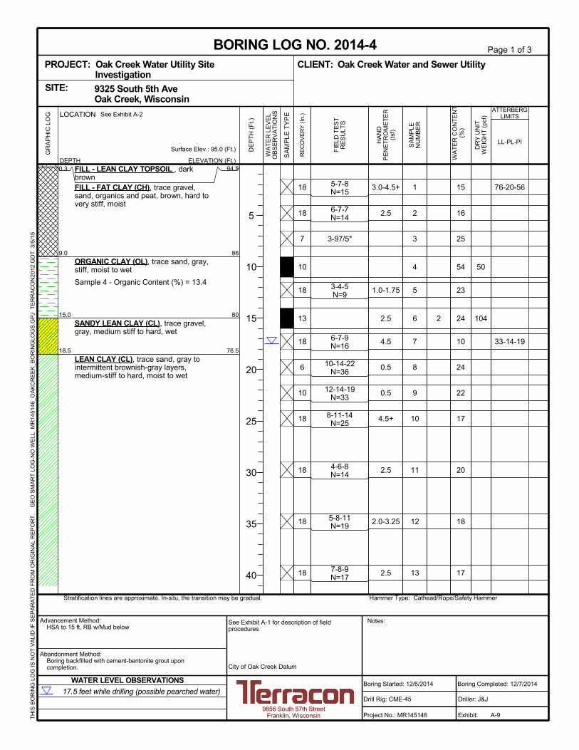
0.3
9.0
15.0
18.5
FILL - LEAN CLAY TOPSOIL , darkbrownFILL - FAT CLAY (CH), trace gravel,sand, organics and peat, brown, hard tovery stiff, moist
ORGANIC CLAY (OL), trace sand, gray,stiff, moist to wet
Sample 4 - Organic Content (%) = 13.4
SANDY LEAN CLAY (CL), trace gravel,gray, medium stiff to hard, wet
LEAN CLAY (CL), trace sand, gray tointermittent brownish-gray layers,medium-stiff to hard, moist to wet
3.0-4.5+
2.5
1.0-1.75
2.5
4.5
0.5
0.5
4.5+
2.5
2.0-3.25
2.5
1
2
3
4
5
6
7
8
9
10
11
12
13
18
18
7
10
18
13
18
6
10
18
18
18
18
94.5
86
80
76.5
2
15
16
25
54
23
24
10
24
22
17
20
18
17
5-7-8N=15
6-7-7N=14
3-97/5"
3-4-5N=9
6-7-9N=16
10-14-22N=36
12-14-19N=33
8-11-14N=25
4-6-8N=14
5-8-11N=19
7-8-9N=17
50
104
76-20-56
33-14-19
See Exhibit A-2
Hammer Type: Cathead/Rope/Safety HammerStratification lines are approximate. In-situ, the transition may be gradual.
LOCATION
DEPTH
GR
AP
HIC
LO
G
TH
IS B
OR
ING
LO
G IS
NO
T V
ALI
D IF
SE
PA
RA
TE
D F
RO
M O
RIG
INA
L R
EP
OR
T.
G
EO
SM
AR
T L
OG
-NO
WE
LL M
R14
5146
_OA
KC
RE
EK
_BO
RIN
GLO
GS
.GP
J T
ER
RA
CO
N20
12.G
DT
3/5
/15
9325 South 5th Ave Oak Creek, WisconsinSITE:
17.5 feet while drilling (possible pearched water)
WATER LEVEL OBSERVATIONS
PROJECT: Oak Creek Water Utility SiteInvestigation
Page 1 of 3
Advancement Method:HSA to 15 ft, RB w/Mud below
Abandonment Method:Boring backfilled with cement-bentonite grout uponcompletion.
9856 South 57th StreetFranklin, Wisconsin
Notes:
Project No.: MR145146
Drill Rig: CME-45
Boring Started: 12/6/2014
BORING LOG NO. 2014-4Oak Creek Water and Sewer UtilityCLIENT:
Driller: J&J
Boring Completed: 12/7/2014
Exhibit:
City of Oak Creek Datum
See Exhibit A-1 for description of fieldprocedures
A-9
HA
ND
PE
NE
TR
OM
ET
ER
(tsf
)
SA
MP
LEN
UM
BE
R
RE
CO
VE
RY
(In
.)
ELEVATION (Ft.)
FIE
LD T
ES
TR
ES
ULT
S
WA
TE
R L
EV
EL
OB
SE
RV
AT
ION
S
Surface Elev.: 95.0 (Ft.) DE
PT
H (
Ft.)
5
10
15
20
25
30
35
40
SA
MP
LE T
YP
E
DR
Y U
NIT
WE
IGH
T (
pcf)
ATTERBERGLIMITS
LL-PL-PI
WA
TE
R C
ON
TE
NT
(%)

LEAN CLAY (CL), trace sand, gray tointermittent brownish-gray layers,medium-stiff to hard, moist to wet(continued)
3.5
3.5
3.25-4.5
3.5-4.25
2.5-3.5
0.75
3.5
3.5
14
15
16
17
18
19
20
21
18
18
18
18
18
18
18
18
18
20
24
23
19
19
17
17
7-10-13N=23
9-12-15N=27
7-9-12N=21
7-10-13N=23
10-10-13N=23
8-11-12N=23
8-13-15N=28
9-11-14N=25
See Exhibit A-2
Hammer Type: Cathead/Rope/Safety HammerStratification lines are approximate. In-situ, the transition may be gradual.
LOCATION
DEPTH
GR
AP
HIC
LO
G
TH
IS B
OR
ING
LO
G IS
NO
T V
ALI
D IF
SE
PA
RA
TE
D F
RO
M O
RIG
INA
L R
EP
OR
T.
G
EO
SM
AR
T L
OG
-NO
WE
LL M
R14
5146
_OA
KC
RE
EK
_BO
RIN
GLO
GS
.GP
J T
ER
RA
CO
N20
12.G
DT
3/5
/15
9325 South 5th Ave Oak Creek, WisconsinSITE:
17.5 feet while drilling (possible pearched water)
WATER LEVEL OBSERVATIONS
PROJECT: Oak Creek Water Utility SiteInvestigation
Page 2 of 3
Advancement Method:HSA to 15 ft, RB w/Mud below
Abandonment Method:Boring backfilled with cement-bentonite grout uponcompletion.
9856 South 57th StreetFranklin, Wisconsin
Notes:
Project No.: MR145146
Drill Rig: CME-45
Boring Started: 12/6/2014
BORING LOG NO. 2014-4Oak Creek Water and Sewer UtilityCLIENT:
Driller: J&J
Boring Completed: 12/7/2014
Exhibit:
City of Oak Creek Datum
See Exhibit A-1 for description of fieldprocedures
A-10
HA
ND
PE
NE
TR
OM
ET
ER
(tsf
)
SA
MP
LEN
UM
BE
R
RE
CO
VE
RY
(In
.)
ELEVATION (Ft.)
WA
TE
RC
ON
TE
NT
(%
)
FIE
LD T
ES
TR
ES
ULT
S
WA
TE
R L
EV
EL
OB
SE
RV
AT
ION
S
Surface Elev.: 95.0 (Ft.) DE
PT
H (
Ft.)
45
50
55
60
65
70
75
80
SA
MP
LE T
YP
E
DR
Y U
NIT
WE
IGH
T (
pcf)
ATTERBERGLIMITS
LL-PL-PI

100.0
LEAN CLAY (CL), trace sand, gray tointermittent brownish-gray layers,medium-stiff to hard, moist to wet(continued)
Boring Terminated at 100 Feet
4.5+
3.0-4.5+
4.5+
2.0
22
23
24
25
18
18
18
18-5
19
20
14
16
14-20-23N=43
16-19-24N=43
13-20-26N=46
13-17-17N=34
See Exhibit A-2
Hammer Type: Cathead/Rope/Safety HammerStratification lines are approximate. In-situ, the transition may be gradual.
LOCATION
DEPTH
GR
AP
HIC
LO
G
TH
IS B
OR
ING
LO
G IS
NO
T V
ALI
D IF
SE
PA
RA
TE
D F
RO
M O
RIG
INA
L R
EP
OR
T.
G
EO
SM
AR
T L
OG
-NO
WE
LL M
R14
5146
_OA
KC
RE
EK
_BO
RIN
GLO
GS
.GP
J T
ER
RA
CO
N20
12.G
DT
3/5
/15
9325 South 5th Ave Oak Creek, WisconsinSITE:
17.5 feet while drilling (possible pearched water)
WATER LEVEL OBSERVATIONS
PROJECT: Oak Creek Water Utility SiteInvestigation
Page 3 of 3
Advancement Method:HSA to 15 ft, RB w/Mud below
Abandonment Method:Boring backfilled with cement-bentonite grout uponcompletion.
9856 South 57th StreetFranklin, Wisconsin
Notes:
Project No.: MR145146
Drill Rig: CME-45
Boring Started: 12/6/2014
BORING LOG NO. 2014-4Oak Creek Water and Sewer UtilityCLIENT:
Driller: J&J
Boring Completed: 12/7/2014
Exhibit:
City of Oak Creek Datum
See Exhibit A-1 for description of fieldprocedures
A-11
HA
ND
PE
NE
TR
OM
ET
ER
(tsf
)
SA
MP
LEN
UM
BE
R
RE
CO
VE
RY
(In
.)
ELEVATION (Ft.)
FIE
LD T
ES
TR
ES
ULT
S
WA
TE
R L
EV
EL
OB
SE
RV
AT
ION
S
Surface Elev.: 95.0 (Ft.) DE
PT
H (
Ft.)
85
90
95
100
SA
MP
LE T
YP
E
DR
Y U
NIT
WE
IGH
T (
pcf)
ATTERBERGLIMITS
LL-PL-PI
UN
CO
NF
INE
DC
OM
PR
ES
SIV
ES
TR
EN
GT
H (
tsf)
WA
TE
RC
ON
TE
NT
(%
)

0.4
3.0
8.5
11.0
15.5
17.0
20.0
FILL - TOPSOIL , clay, dark brown,moistFILL - LEAN CLAY (CL), trace sand,topsoil, and gravel, brown, moistFILL - LEAN CLAY (CL), trace coal,black to and green-gray, moist
ORGANIC SILT (OL), trace shellfragments, green-gray, loose, moist
LEAN CLAY (CL), trace sand andgravel, gray, stiff to very stiff, moist
Note: intermittent gray silt seams.
POORLY GRADED SAND (SP), tracesilt and gravel, gray, medium dense, wetNote: intermittent gray sandy lean clayseams.LEAN CLAY (CL), trace sand andgravel, gray, hard, moistBoring Terminated at 20 Feet
1.0-2.0
1.75-3.25
4.5+
1
2
3
4
5
6
7
8
10
18
14
18
18
18
18
18
94.5
92
86.5
84
79.5
78
75
2.5
10.5
428
8
5.8
0.5
0.3-1.0
1.6
5-7-7N=14
7-8-11N=19
4-4-6N=10
2-3-3N=6
3-4-5N=9
4-5-5N=10
10-12-8N=20
12-15-18N=33
See Exhibit A-2
Hammer Type: Cathead/Rope/Safety HammerStratification lines are approximate. In-situ, the transition may be gradual.
LOCATION
DEPTH
GR
AP
HIC
LO
G
TH
IS B
OR
ING
LO
G IS
NO
T V
ALI
D IF
SE
PA
RA
TE
D F
RO
M O
RIG
INA
L R
EP
OR
T.
G
EO
SM
AR
T L
OG
-NO
WE
LL M
R14
5146
_OA
KC
RE
EK
_BO
RIN
GLO
GS
.GP
J T
ER
RA
CO
N20
12.G
DT
3/5
/15
9325 South 5th Ave Oak Creek, WisconsinSITE:
14 feet while drilling
WATER LEVEL OBSERVATIONS
PROJECT: Oak Creek Water Utility SiteInvestigation
Page 1 of 1
Advancement Method:HSA
Abandonment Method:Boring backfilled with cement-bentonite grout uponcompletion.
9856 South 57th StreetFranklin, Wisconsin
Notes:
Project No.: MR145146
Drill Rig: CME-45
Boring Started: 2/7/2015
BORING LOG NO. 2014-4AOak Creek Water and Sewer UtilityCLIENT:
Driller: J&J
Boring Completed: 2/7/2015
Exhibit:
City of Oak Creek Datum
See Exhibit A-1 for description of fieldprocedures
A-12
HA
ND
PE
NE
TR
OM
ET
ER
(tsf
)
SA
MP
LEN
UM
BE
R
RE
CO
VE
RY
(In
.)
ELEVATION (Ft.)
WA
TE
RC
ON
TE
NT
(%
)
FIE
LD T
ES
TR
ES
ULT
S
WA
TE
R L
EV
EL
OB
SE
RV
AT
ION
S
Surface Elev.: 95.0 (Ft.) DE
PT
H (
Ft.)
5
10
15
20
SA
MP
LE T
YP
E
DR
Y U
NIT
WE
IGH
T (
pcf)
ATTERBERGLIMITS
LL-PL-PI

1.5
6.0
12.0
13.5
14.5
FILL - LEAN CLAY TOPSOIL , darkbrownFILL - LEAN CLAY (CL), trace sand,brown to gray, hard to very stiff, moist
FILL - LEAN CLAY/FAT CLAY (CL/CH),trace gravel, organics, and peat, darkbrown to black, soft to stiff, moist
SILT (ML), trace clay and organics,gray, loose, moistPOORLY GRADED SAND (SP), gray,wetLEAN CLAY (CL), trace sand, gray, stiffto hard, moist
Note: Intermittent silt seams noted in
4.5+
2.25
0.25
1.0
3.5
3.75-4.5+
4.25-4.5+
3.5-4.5+
0.25
2.0
1.75
2.5
2.25-3.5
1
2
3
4
5
6
7
8
9
10
11
12
13
14
14
10
7
12
18
24
18
18
18
8
12
18
18
18
92.5
88
82
80.5
79.5
<0.6
<0.6
<0.6
<0.6
<0.6
<0.6
<0.6
<0.6
<0.6
<0.6
<0.6
<0.6
13
20
65
22
19
18
20
19
26
24
21
19
21
8-9-11N=20
5-4-5N=9
2-1-5N=6
1-2-3N=5
8-11-13N=24
10-12-15N=27
6-8-13N=21
9-11-12N=23
10-10-10N=20
5-6-8N=14
6-8-9N=17
7-10-14N=24
111 23-8-15
See Exhibit A-2
Hammer Type: Cathead/Rope/Safety HammerStratification lines are approximate. In-situ, the transition may be gradual.
LOCATION
DEPTH
GR
AP
HIC
LO
G
TH
IS B
OR
ING
LO
G IS
NO
T V
ALI
D IF
SE
PA
RA
TE
D F
RO
M O
RIG
INA
L R
EP
OR
T.
G
EO
SM
AR
T L
OG
-NO
WE
LL M
R14
5146
_OA
KC
RE
EK
_BO
RIN
GLO
GS
.GP
J T
ER
RA
CO
N20
12.G
DT
3/5
/15
9325 South 5th Ave Oak Creek, WisconsinSITE:
13.5 feet while sampling
18 feet before casing removal
11.5 feet at completion of drilling
WATER LEVEL OBSERVATIONS
PROJECT: Oak Creek Water Utility SiteInvestigation
Page 1 of 2
Advancement Method:HSA to 15 ft, RB w/Mud below
Abandonment Method:Boring backfilled with cement-bentonite grout uponcompletion.
9856 South 57th StreetFranklin, Wisconsin
Notes:
Project No.: MR145146
Drill Rig: CME-45
Boring Started: 12/9/2014
BORING LOG NO. 2014-5Oak Creek Water and Sewer UtilityCLIENT:
Driller: J&J
Boring Completed: 12/9/2014
Exhibit:
City of Oak Creek Datum
See Exhibit A-1 for description of fieldprocedures
A-13
HA
ND
PE
NE
TR
OM
ET
ER
(tsf
)
SA
MP
LEN
UM
BE
R
RE
CO
VE
RY
(In
.)
ELEVATION (Ft.)
FIE
LD T
ES
TR
ES
ULT
S
WA
TE
R L
EV
EL
OB
SE
RV
AT
ION
S
Surface Elev.: 94.1 (Ft.) DE
PT
H (
Ft.)
5
10
15
20
25
30
35
40
SA
MP
LE T
YP
E
DR
Y U
NIT
WE
IGH
T (
pcf)
ATTERBERGLIMITS
LL-PL-PI
UN
CO
NF
INE
DC
OM
PR
ES
SIV
ES
TR
EN
GT
H (
tsf)
WA
TE
RC
ON
TE
NT
(%
)

60.0
samples 14, 15, 16, and 18.LEAN CLAY (CL), trace sand, gray, stiffto hard, moist (continued)
Boring Terminated at 60 Feet
3.0
1.75-2.75
3.0-4.0
3.75-4.5
15
16
17
18
18
18
18
1834
<0.6
<0.6
<0.6
<0.6
18
26
26
22
7-10-13N=23
6-8-10N=18
8-10-14N=24
11-12-16N=28
See Exhibit A-2
Hammer Type: Cathead/Rope/Safety HammerStratification lines are approximate. In-situ, the transition may be gradual.
LOCATION
DEPTH
GR
AP
HIC
LO
G
TH
IS B
OR
ING
LO
G IS
NO
T V
ALI
D IF
SE
PA
RA
TE
D F
RO
M O
RIG
INA
L R
EP
OR
T.
G
EO
SM
AR
T L
OG
-NO
WE
LL M
R14
5146
_OA
KC
RE
EK
_BO
RIN
GLO
GS
.GP
J T
ER
RA
CO
N20
12.G
DT
3/5
/15
9325 South 5th Ave Oak Creek, WisconsinSITE:
13.5 feet while sampling
18 feet before casing removal
11.5 feet at completion of drilling
WATER LEVEL OBSERVATIONS
PROJECT: Oak Creek Water Utility SiteInvestigation
Page 2 of 2
Advancement Method:HSA to 15 ft, RB w/Mud below
Abandonment Method:Boring backfilled with cement-bentonite grout uponcompletion.
9856 South 57th StreetFranklin, Wisconsin
Notes:
Project No.: MR145146
Drill Rig: CME-45
Boring Started: 12/9/2014
BORING LOG NO. 2014-5Oak Creek Water and Sewer UtilityCLIENT:
Driller: J&J
Boring Completed: 12/9/2014
Exhibit:
City of Oak Creek Datum
See Exhibit A-1 for description of fieldprocedures
A-14
HA
ND
PE
NE
TR
OM
ET
ER
(tsf
)
SA
MP
LEN
UM
BE
R
RE
CO
VE
RY
(In
.)
ELEVATION (Ft.)
WA
TE
RC
ON
TE
NT
(%
)
FIE
LD T
ES
TR
ES
ULT
S
WA
TE
R L
EV
EL
OB
SE
RV
AT
ION
S
Surface Elev.: 94.1 (Ft.) DE
PT
H (
Ft.)
45
50
55
60
SA
MP
LE T
YP
E
DR
Y U
NIT
WE
IGH
T (
pcf)
ATTERBERGLIMITS
LL-PL-PI

0.2
3.5
9.0
14.0
FILL - LEAN CLAY TOPSOIL , darkbrownFILL - SANDY LEAN CLAY (CL), traceasphalt and cinders, brown, hard, moistFILL - LEAN CLAY (CL), trace sand andgravel, brown to dark brown, medium stiffto stiff, moist
LEAN CLAY (CL), trace sand andgravel, brown, medium stiff to stiff
Note: Intermittent silt seams noted insample 5.
LEAN CLAY (CL), trace sand, gray,medium stiff to very stiff, moist to wet
Note: Intermittent silt seams noted insample 8.
4.5+
0.5
0.5-1.0
1.5
0.5-1.5
2.0
2.5-3.75
1.75
1.0-2.0
1.75
0.5-0.75
0.5-1.0
2.0-2.75
1
2
3
4
5
6
7
8
9
10
11
12
13
13
10
14
16
18
19
18
18
18
18
18
18
18
95
92
86.5
81.5
1
3
<0.6
<0.6
<0.6
<0.6
<0.6
<0.6
<0.6
<0.6
<0.6
<0.6
<0.6
12
17
35
21
15
18
23
21
22
23
27
23
18
9-11-11N=22
3-4-4N=8
2-4-5N=9
3-4-4N=8
5-6-7N=13
4-5-7N=12
4-5-6N=11
4-5-6N=11
2-3-4N=7
2-3-4N=7
4-7-8N=15
105
110
38-16-22
29-13-16
See Exhibit A-2
Hammer Type: Cathead/Rope/Safety HammerStratification lines are approximate. In-situ, the transition may be gradual.
LOCATION
DEPTH
GR
AP
HIC
LO
G
TH
IS B
OR
ING
LO
G IS
NO
T V
ALI
D IF
SE
PA
RA
TE
D F
RO
M O
RIG
INA
L R
EP
OR
T.
G
EO
SM
AR
T L
OG
-NO
WE
LL M
R14
5146
_OA
KC
RE
EK
_BO
RIN
GLO
GS
.GP
J T
ER
RA
CO
N20
12.G
DT
3/5
/15
9325 South 5th Ave Oak Creek, WisconsinSITE:
Not encounteredWATER LEVEL OBSERVATIONS
PROJECT: Oak Creek Water Utility SiteInvestigation
Page 1 of 2
Advancement Method:HSA to 15 ft, RB w/Mud below
Abandonment Method:Boring backfilled with cement-bentonite grout uponcompletion.
9856 South 57th StreetFranklin, Wisconsin
Notes:
Project No.: MR145146
Drill Rig: CME-45
Boring Started: 12/8/2014
BORING LOG NO. 2014-6Oak Creek Water and Sewer UtilityCLIENT:
Driller: J&J
Boring Completed: 12/8/2014
Exhibit:
City of Oak Creek Datum
See Exhibit A-1 for description of fieldprocedures
A-15
HA
ND
PE
NE
TR
OM
ET
ER
(tsf
)
SA
MP
LEN
UM
BE
R
RE
CO
VE
RY
(In
.)
ELEVATION (Ft.)
FIE
LD T
ES
TR
ES
ULT
S
WA
TE
R L
EV
EL
OB
SE
RV
AT
ION
S
Surface Elev.: 95.4 (Ft.) DE
PT
H (
Ft.)
5
10
15
20
25
30
35
40
SA
MP
LE T
YP
E
DR
Y U
NIT
WE
IGH
T (
pcf)
ATTERBERGLIMITS
LL-PL-PI
UN
CO
NF
INE
DC
OM
PR
ES
SIV
ES
TR
EN
GT
H (
tsf)
WA
TE
RC
ON
TE
NT
(%
)

60.0
LEAN CLAY (CL), trace sand, gray,medium stiff to very stiff, moist to wet(continued)
Note: Intermittent silt seams noted insample 15.
Boring Terminated at 60 Feet
2.5
3.0
3.0-3.5
3.75
14
15
16
17
18
18
18
1835.5
<0.6
<0.6
<0.6
<0.6
17
18
24
22
5-8-11N=19
7-10-12N=22
8-11-13N=24
7-11-15N=26
See Exhibit A-2
Hammer Type: Cathead/Rope/Safety HammerStratification lines are approximate. In-situ, the transition may be gradual.
LOCATION
DEPTH
GR
AP
HIC
LO
G
TH
IS B
OR
ING
LO
G IS
NO
T V
ALI
D IF
SE
PA
RA
TE
D F
RO
M O
RIG
INA
L R
EP
OR
T.
G
EO
SM
AR
T L
OG
-NO
WE
LL M
R14
5146
_OA
KC
RE
EK
_BO
RIN
GLO
GS
.GP
J T
ER
RA
CO
N20
12.G
DT
3/5
/15
9325 South 5th Ave Oak Creek, WisconsinSITE:
Not encounteredWATER LEVEL OBSERVATIONS
PROJECT: Oak Creek Water Utility SiteInvestigation
Page 2 of 2
Advancement Method:HSA to 15 ft, RB w/Mud below
Abandonment Method:Boring backfilled with cement-bentonite grout uponcompletion.
9856 South 57th StreetFranklin, Wisconsin
Notes:
Project No.: MR145146
Drill Rig: CME-45
Boring Started: 12/8/2014
BORING LOG NO. 2014-6Oak Creek Water and Sewer UtilityCLIENT:
Driller: J&J
Boring Completed: 12/8/2014
Exhibit:
City of Oak Creek Datum
See Exhibit A-1 for description of fieldprocedures
A-16
HA
ND
PE
NE
TR
OM
ET
ER
(tsf
)
SA
MP
LEN
UM
BE
R
RE
CO
VE
RY
(In
.)
ELEVATION (Ft.)
WA
TE
RC
ON
TE
NT
(%
)
FIE
LD T
ES
TR
ES
ULT
S
WA
TE
R L
EV
EL
OB
SE
RV
AT
ION
S
Surface Elev.: 95.4 (Ft.) DE
PT
H (
Ft.)
45
50
55
60
SA
MP
LE T
YP
E
DR
Y U
NIT
WE
IGH
T (
pcf)
ATTERBERGLIMITS
LL-PL-PI

0.8
3.5
10.5
40.0
FILL - LEAN CLAY TOPSOIL , tracegravel, dark brownFILL - LEAN CLAY/FAT CLAY (CL/CH),trace sand, gravel, organics and peat,brown and dark brown to intermittentblack layers, very stiff, moist to wetFILL - LEAN CLAY/FAT CLAY (CL/CH),trace sand, gravel, organics and peat,brown and dark brown to intermittentblack layers, very soft to soft, moist towetSample 2 - Organic Content (%) = 19.6
LEAN CLAY (CL), trace sand, gray, stiffto hard, moist to wet
Note: Intermittent silt seams in sample13.
Boring Terminated at 40 Feet
3.75
0.25
0.25-0.5
1.5-3.0
4.0-4.5+
2.5-3.5
3.5-4.25
2.75
2.5
2.0-3.25
3.5
3.0-3.75
3.5
2.75
3.0
1
2
3
4
5
6
7
8
9
10
11
12
13
14
15
16
18
15
18
18
18
18
18
18
18
18
18
18
18
18
18
18
89.5
86.5
79.5
50
<0.6
<0.6
<0.6
<0.6
<0.6
<0.6
<0.6
<0.6
<0.6
<0.6
<0.6
<0.6
<0.6
<0.6
<0.6
<0.6
20
85
195
116
19
16
18
16
19
19
18
16
15
15
17
20
5-6-7N=13
2-3-2N=5
0-1-0N=1
1-0-1N=1
2-4-4N=8
5-9-13N=22
6-8-12N=20
7-11-14N=25
6-10-13N=23
5-6-8N=14
5-8-11N=19
7-11-13N=24
7-10-13N=23
8-10-13N=23
7-10-11N=21
8-9-11N=20
See Exhibit A-2
Hammer Type: Cathead/Rope/Safety HammerStratification lines are approximate. In-situ, the transition may be gradual.
LOCATION
DEPTH
GR
AP
HIC
LO
G
TH
IS B
OR
ING
LO
G IS
NO
T V
ALI
D IF
SE
PA
RA
TE
D F
RO
M O
RIG
INA
L R
EP
OR
T.
G
EO
SM
AR
T L
OG
-NO
WE
LL M
R14
5146
_OA
KC
RE
EK
_BO
RIN
GLO
GS
.GP
J T
ER
RA
CO
N20
12.G
DT
3/5
/15
9325 South 5th Ave Oak Creek, WisconsinSITE:
Not encounteredWATER LEVEL OBSERVATIONS
PROJECT: Oak Creek Water Utility SiteInvestigation
Page 1 of 1
Advancement Method:HSA
Abandonment Method:Installed 2" PVC monitoring well, screened from 30 to 40feet
9856 South 57th StreetFranklin, Wisconsin
Notes:
Project No.: MR145146
Drill Rig: CME-45
Boring Started: 12/11/2014
BORING LOG NO. 2014-7Oak Creek Water and Sewer UtilityCLIENT:
Driller: J&J
Boring Completed: 12/11/2014
Exhibit:
City of Oak Creek Datum
See Exhibit A-1 for description of fieldprocedures
A-17
HA
ND
PE
NE
TR
OM
ET
ER
(tsf
)
SA
MP
LEN
UM
BE
R
RE
CO
VE
RY
(In
.)
ELEVATION (Ft.)
FIE
LD T
ES
TR
ES
ULT
S
WA
TE
R L
EV
EL
OB
SE
RV
AT
ION
S
Surface Elev.: 90.0 (Ft.) DE
PT
H (
Ft.)
5
10
15
20
25
30
35
40
SA
MP
LE T
YP
E
DR
Y U
NIT
WE
IGH
T (
pcf)
ATTERBERGLIMITS
LL-PL-PI
UN
CO
NF
INE
DC
OM
PR
ES
SIV
ES
TR
EN
GT
H (
tsf)
WA
TE
RC
ON
TE
NT
(%
)

0.5
6.5
9.0
10.5
14.5
15.5
17.5
40.0
FILL - LEAN CLAY TOPSOIL , darkbrown, moistFILL - LEAN CLAY , trace sand, topsoil,gravel, and rubble, brown, moist
PEAT (PT), dark brown, very loose,moist
ORGANIC CLAY (OL), trace silt, tan,very loose, moistSILT (ML), trace shell fragments,greenish gray, very loose, moist
PEAT (PT), trace wood fragments, darkbrown, very loose, moistORGANIC SILT (OL), trace sand, gray,loose, wetLEAN CLAY (CL), trace sand andgravel, gray, stiff to very stiff, moist
Boring Terminated at 40 Feet
1.50
0.25
2.5-3.5
2.75-3.5
3.0-4.0
2.0
1.25-2.0
2.0
3.75
2.5-3.5
3.5
1
2
3
4
5
6
7
8
9
10
11
12
13
14
15
16
1
14
18
18
18
18
18
18
18
18
18
18
18
18
18
18
91
85
82.5
81
77
76
74
51.5
1.4
1.4
1.8
1.8-1.4
1.8
1.8-2.8
1.3
1.4
1.3
1.6
1.6
1.6
1.6
1.8
1.4
1.3
17
23
73
92
79
73
98
19
18
18
22
20
19
18
16
4-6-8N=14
4-4-6N=10
1-2-1N=3
1-1-2N=3
1-1-1N=2
1-1-2N=3
3-3-4N=7
7-9-11N=20
8-10-12N=22
6-8-11N=19
6-7-8N=15
4-4-6N=10
5-5-5N=10
6-8-12N=20
5-8-11N=19
7-9-13N=22
See Exhibit A-2
Hammer Type: Cathead/Rope/Safety HammerStratification lines are approximate. In-situ, the transition may be gradual.
LOCATION
DEPTH
GR
AP
HIC
LO
G
TH
IS B
OR
ING
LO
G IS
NO
T V
ALI
D IF
SE
PA
RA
TE
D F
RO
M O
RIG
INA
L R
EP
OR
T.
G
EO
SM
AR
T L
OG
-NO
WE
LL M
R14
5146
_OA
KC
RE
EK
_BO
RIN
GLO
GS
.GP
J T
ER
RA
CO
N20
12.G
DT
3/5
/15
9325 South 5th Ave Oak Creek, WisconsinSITE:
15.5 feet while sampling
31 feet at completion of drilling
WATER LEVEL OBSERVATIONS
PROJECT: Oak Creek Water Utility SiteInvestigation
Page 1 of 1
Advancement Method:HSA
Abandonment Method:Boring backfilled with cement-bentonite grout uponcompletion.
9856 South 57th StreetFranklin, Wisconsin
Notes:
Project No.: MR145146
Drill Rig: CME-45
Boring Started: 2/6/2015
BORING LOG NO. 2014-8Oak Creek Water and Sewer UtilityCLIENT:
Driller: J&J
Boring Completed: 2/6/2015
Exhibit:
City of Oak Creek Datum
See Exhibit A-1 for description of fieldprocedures
A-18
HA
ND
PE
NE
TR
OM
ET
ER
(tsf
)
SA
MP
LEN
UM
BE
R
RE
CO
VE
RY
(In
.)
ELEVATION (Ft.)
WA
TE
RC
ON
TE
NT
(%
)
FIE
LD T
ES
TR
ES
ULT
S
WA
TE
R L
EV
EL
OB
SE
RV
AT
ION
S
Surface Elev.: 91.5 (Ft.) DE
PT
H (
Ft.)
5
10
15
20
25
30
35
40
SA
MP
LE T
YP
E
DR
Y U
NIT
WE
IGH
T (
pcf)
ATTERBERGLIMITS
LL-PL-PI

18.0
Blind Drilled to 18 feet, see B-2014-8 forclassifications.
LEAN CLAY (CL), trace sand andgravel, gray, very stiff, moist
2.5
2.5-3.5
1
2
12
18
73.56-6-9N=15
6-6-9N=15
See Exhibit A-2
Hammer Type: Cathead/Rope/Safety HammerStratification lines are approximate. In-situ, the transition may be gradual.
LOCATION
DEPTH
GR
AP
HIC
LO
G
TH
IS B
OR
ING
LO
G IS
NO
T V
ALI
D IF
SE
PA
RA
TE
D F
RO
M O
RIG
INA
L R
EP
OR
T.
G
EO
SM
AR
T L
OG
-NO
WE
LL M
R14
5146
_OA
KC
RE
EK
_BO
RIN
GLO
GS
.GP
J T
ER
RA
CO
N20
12.G
DT
3/5
/15
9325 South 5th Ave Oak Creek, WisconsinSITE:
Water level not determinedWATER LEVEL OBSERVATIONS
PROJECT: Oak Creek Water Utility SiteInvestigation
Page 1 of 3
Advancement Method:HSA to 10 ft, RB w/Mud below
Abandonment Method:Boring backfilled with cement-bentonite grout uponcompletion.
9856 South 57th StreetFranklin, Wisconsin
Notes:
Project No.: MR145146
Drill Rig: CME-45
Boring Started: 2/23/2015
BORING LOG NO. 2014-8PMTOak Creek Water and Sewer UtilityCLIENT:
Driller: J&J
Boring Completed: 2/23/2015
Exhibit:
City of Oak Creek Datum
See Exhibit A-1 for description of fieldprocedures
A-19
HA
ND
PE
NE
TR
OM
ET
ER
(tsf
)
SA
MP
LEN
UM
BE
R
RE
CO
VE
RY
(In
.)
ELEVATION (Ft.)
FIE
LD T
ES
TR
ES
ULT
S
WA
TE
R L
EV
EL
OB
SE
RV
AT
ION
S
Surface Elev.: 91.5 (Ft.) DE
PT
H (
Ft.)
5
10
15
20
25
30
35
40
SA
MP
LE T
YP
E
DR
Y U
NIT
WE
IGH
T (
pcf)
ATTERBERGLIMITS
LL-PL-PI
UN
CO
NF
INE
DC
OM
PR
ES
SIV
ES
TR
EN
GT
H (
tsf)
WA
TE
RC
ON
TE
NT
(%
)

LEAN CLAY (CL), trace sand andgravel, gray, very stiff, moist (continued)
Drillers Note: water loss from 47 to 48feet, possible sand layer. After PMT 3(50 -52 feet) could not get roller bit downhole without plugging with clay. Startednew hole 2.5 feet east. Used HSA to 50feet, used as casing, then RB to nextPMT interval at 80to 82 feet.
3.5-4.25
3.5-4.0
3
4
18
18
8-11-13N=24
11-13-17N=30
See Exhibit A-2
Hammer Type: Cathead/Rope/Safety HammerStratification lines are approximate. In-situ, the transition may be gradual.
LOCATION
DEPTH
GR
AP
HIC
LO
G
TH
IS B
OR
ING
LO
G IS
NO
T V
ALI
D IF
SE
PA
RA
TE
D F
RO
M O
RIG
INA
L R
EP
OR
T.
G
EO
SM
AR
T L
OG
-NO
WE
LL M
R14
5146
_OA
KC
RE
EK
_BO
RIN
GLO
GS
.GP
J T
ER
RA
CO
N20
12.G
DT
3/5
/15
9325 South 5th Ave Oak Creek, WisconsinSITE:
Water level not determinedWATER LEVEL OBSERVATIONS
PROJECT: Oak Creek Water Utility SiteInvestigation
Page 2 of 3
Advancement Method:HSA to 10 ft, RB w/Mud below
Abandonment Method:Boring backfilled with cement-bentonite grout uponcompletion.
9856 South 57th StreetFranklin, Wisconsin
Notes:
Project No.: MR145146
Drill Rig: CME-45
Boring Started: 2/23/2015
BORING LOG NO. 2014-8PMTOak Creek Water and Sewer UtilityCLIENT:
Driller: J&J
Boring Completed: 2/23/2015
Exhibit:
City of Oak Creek Datum
See Exhibit A-1 for description of fieldprocedures
A-20
HA
ND
PE
NE
TR
OM
ET
ER
(tsf
)
SA
MP
LEN
UM
BE
R
RE
CO
VE
RY
(In
.)
ELEVATION (Ft.)
WA
TE
RC
ON
TE
NT
(%
)
FIE
LD T
ES
TR
ES
ULT
S
WA
TE
R L
EV
EL
OB
SE
RV
AT
ION
S
Surface Elev.: 91.5 (Ft.) DE
PT
H (
Ft.)
45
50
55
60
65
70
75
80
SA
MP
LE T
YP
E
DR
Y U
NIT
WE
IGH
T (
pcf)
ATTERBERGLIMITS
LL-PL-PI

85.0
LEAN CLAY (CL), trace sand andgravel, gray, very stiff, moist (continued)
Boring Terminated at 85 Feet6.5
See Exhibit A-2
Hammer Type: Cathead/Rope/Safety HammerStratification lines are approximate. In-situ, the transition may be gradual.
LOCATION
DEPTH
GR
AP
HIC
LO
G
TH
IS B
OR
ING
LO
G IS
NO
T V
ALI
D IF
SE
PA
RA
TE
D F
RO
M O
RIG
INA
L R
EP
OR
T.
G
EO
SM
AR
T L
OG
-NO
WE
LL M
R14
5146
_OA
KC
RE
EK
_BO
RIN
GLO
GS
.GP
J T
ER
RA
CO
N20
12.G
DT
3/5
/15
9325 South 5th Ave Oak Creek, WisconsinSITE:
Water level not determinedWATER LEVEL OBSERVATIONS
PROJECT: Oak Creek Water Utility SiteInvestigation
Page 3 of 3
Advancement Method:HSA to 10 ft, RB w/Mud below
Abandonment Method:Boring backfilled with cement-bentonite grout uponcompletion.
9856 South 57th StreetFranklin, Wisconsin
Notes:
Project No.: MR145146
Drill Rig: CME-45
Boring Started: 2/23/2015
BORING LOG NO. 2014-8PMTOak Creek Water and Sewer UtilityCLIENT:
Driller: J&J
Boring Completed: 2/23/2015
Exhibit:
City of Oak Creek Datum
See Exhibit A-1 for description of fieldprocedures
A-21
HA
ND
PE
NE
TR
OM
ET
ER
(tsf
)
SA
MP
LEN
UM
BE
R
RE
CO
VE
RY
(In
.)
ELEVATION (Ft.)
WA
TE
RC
ON
TE
NT
(%
)
FIE
LD T
ES
TR
ES
ULT
S
WA
TE
R L
EV
EL
OB
SE
RV
AT
ION
S
Surface Elev.: 91.5 (Ft.) DE
PT
H (
Ft.)
85
SA
MP
LE T
YP
E
DR
Y U
NIT
WE
IGH
T (
pcf)
ATTERBERGLIMITS
LL-PL-PI

0.3
4.5
5.5
15.0
40.0
FILL - LEAN CLAY TOPSOIL , darkbrownFILL - LEAN CLAY , trace sand, topsoil,and gravel, brown, moist
FILL - LEAN CLAY TOPSOIL , tracegravel, dark brown, moistLEAN CLAY (CL), trace sand andgravel, brown, very stiff to hard, moist
LEAN CLAY (CL), trace sand andgravel, gray, stiff to very stiff, moist
Boring Terminated at 40 Feet
3.5
2.0
3.25-4.5+
4.5+
4.5+
2.5-1.0
1.0-1.5
1.0
1.0-1.5
1.25
1.25-2.0
1.25-1.75
1.0-1.5
1.25-1.75
2.5-3.5
2.5
1
2
3
4
5
6
7
8
9
10
11
12
13
14
15
16
8
12
18
18
18
18
18
18
18
18
18
18
18
18
18
18
96
91.5
90.5
81
56
1.4
1.6
1.6
1.6
1.6
1.8
1.6
1.6
1.6
1.6
1.6
1.6
1.4
1.6
1.8
1.6
15
20
19
19
19
23
19
25
20
20
19
19
12
19
19
16
4-5-4N=9
3-4-3N=7
5-7-9N=16
8-11-15N=26
8-11-14N=25
5-6-5N=11
3-3-4N=7
3-3-4N=7
4-4-4N=8
4-5-5N=10
4-5-6N=11
4-5-5N=10
3-4-4N=8
3-5-6N=11
6-8-10N=18
7-7-9N=16
See Exhibit A-2
Hammer Type: Cathead/Rope/Safety HammerStratification lines are approximate. In-situ, the transition may be gradual.
LOCATION
DEPTH
GR
AP
HIC
LO
G
TH
IS B
OR
ING
LO
G IS
NO
T V
ALI
D IF
SE
PA
RA
TE
D F
RO
M O
RIG
INA
L R
EP
OR
T.
G
EO
SM
AR
T L
OG
-NO
WE
LL M
R14
5146
_OA
KC
RE
EK
_BO
RIN
GLO
GS
.GP
J T
ER
RA
CO
N20
12.G
DT
3/5
/15
9325 South 5th Ave Oak Creek, WisconsinSITE:
Not encounteredWATER LEVEL OBSERVATIONS
PROJECT: Oak Creek Water Utility SiteInvestigation
Page 1 of 1
Advancement Method:HSA
Abandonment Method:Boring backfilled with cement-bentonite grout uponcompletion.
9856 South 57th StreetFranklin, Wisconsin
Notes:
Project No.: MR145146
Drill Rig: CME-45
Boring Started: 2/6/2015
BORING LOG NO. 2014-9Oak Creek Water and Sewer UtilityCLIENT:
Driller: J&J
Boring Completed: 2/6/2015
Exhibit:
City of Oak Creek Datum
See Exhibit A-1 for description of fieldprocedures
A-22
HA
ND
PE
NE
TR
OM
ET
ER
(tsf
)
SA
MP
LEN
UM
BE
R
RE
CO
VE
RY
(In
.)
ELEVATION (Ft.)
WA
TE
RC
ON
TE
NT
(%
)
FIE
LD T
ES
TR
ES
ULT
S
WA
TE
R L
EV
EL
OB
SE
RV
AT
ION
S
Surface Elev.: 96.0 (Ft.) DE
PT
H (
Ft.)
5
10
15
20
25
30
35
40
SA
MP
LE T
YP
E
DR
Y U
NIT
WE
IGH
T (
pcf)
ATTERBERGLIMITS
LL-PL-PI

ATTACHMENTS B
LABORATORY TEST RESULTS

0
10
20
30
40
50
60
0 20 40 60 80 100
CH o
r
OH
CL o
r
OL
ML or OL
MH or OH
PL PISample ID DescriptionFines
PLASTICITY
INDEX
LIQUID LIMIT
"U" L
ine
"A" L
ine
29
33
63
32
76
33
23
38
29
17
18
22
18
20
14
8
16
13
12
15
41
14
56
19
15
22
16
LL USCS
2014-2
2014-2
2014-3
2014-3
2014-4
2014-4
2014-5
2014-6
2014-6
ATTERBERG LIMITS RESULTSASTM D4318
9856 South 57th StreetFranklin, Wisconsin
PROJECT NUMBER: MR145146PROJECT: Oak Creek Water Utility Site
Investigation
SITE: 9325 South 5th Ave Oak Creek, Wisconsin
CLIENT: Oak Creek Water and Sewer Utility Oak Creek, WI
EXHIBIT: B-1
LAB
OR
AT
OR
Y T
ES
TS
AR
E N
OT
VA
LID
IF S
EP
AR
AT
ED
FR
OM
OR
IGIN
AL
RE
PO
RT
.
AT
TE
RB
ER
G L
IMIT
S M
R14
5146
_OA
KC
RE
EK
_BO
RIN
GLO
GS
.GP
J T
ER
RA
CO
N20
12.G
DT
1/6
/15
CL-ML

UNCONFINED COMPRESSION TEST - ASTM D2166
GENERAL INFORMATIONProject Number: MR145146
Project Name:Location: Diameter (in) Height (in)
Boring Number: 2014-2 1 2.842 5.975
Sample Number: ST-4 2 2.837 5.967
Sample Depth (ft.): 9-11 3 2.836 5.969Test Date: 12/22/2014 Average 2.838 5.970
Sample Date: 12/5/2014
Sample Description: Grayish-Brown Lean Clay, Trace Sand and Gravel
SAMPLE INFORMATION TEST DATA CALCULATIONSInitial Diameter (in.): 2.838 Time Values Strain Load (Zero) Corrected Strain Stress Youngs
Initial Height (in.): 5.970 Stop watch (inches) (lbs) Load (lbs) (%) (psi) Modulus (psi)
Specimen Weight (gms.): 1312.40 10:42 AM 0.000 0.0 0.0 0.00 0.000 0.0
Assumed Specific Gravity (SpG): 2.700 0.050 27.0 27.0 0.84 4.232 505.3
MOISTURE CONTENT DETERMINATION 0.100 42.0 42.0 1.67 6.527 389.7
Container Number: A-28 0.150 55.0 55.0 2.51 8.474 337.3
Wt. Container + Wet Soil (gms.): 165.30 0.200 65.0 65.0 3.35 9.929 296.4
Wt. Container + Dry Soil (gms.): 145.20 0.250 72.0 72.0 4.19 10.903 260.4
Wt. Container (gms.): 31.70 0.300 79.0 79.0 5.02 11.858 236.0
OTHER DATA 0.350 84.0 84.0 5.86 12.498 213.2
Strain Rate (in./min): 0.110 0.400 87.0 87.0 6.70 12.829 191.5
Final Strain Dial Reading (in.): 0.950 0.450 92.0 92.0 7.54 13.444 178.4
RESULTS 0.500 95.0 95.0 8.37 13.757 164.3
Wet Density (pcf): 132.35 0.550 99.0 99.0 9.21 14.205 154.2
Dry Density (pcf): 112.44 0.600 102.0 102.0 10.05 14.501 144.3
Estimated Degree of Saturation: 95.94 0.650 105.0 105.0 10.89 14.788 135.8
Moisture Content (%): 17.71 0.700 107.0 107.0 11.72 14.928 127.3
Estimated Void Ratio: 0.498 0.750 110.0 110.0 12.56 15.201 121.0
Test Duration (min.): 8.64 0.800 112.0 112.0 13.40 15.329 114.4
Time To Failure (min): 8.64 0.850 115.0 115.0 14.24 15.588 109.5
Maximum Deviator Stress (psf): 2277 0.900 117.0 117.0 15.07 15.704 104.2
Axial Strain at Failure (%): 15.91 0.950 119.0 119.0 15.91 15.815 99.4
Length / Diameter Ratio: 2.10 10:50 AM 1.000 0.0 0.00 0.000 0.0
Maximum Cohesion (psf): 1139 0.0 0.00 0.000 0.0
0.0 0.00 0.000 0.0
0.0 0.00 0.000 0.0
0.0 0.00 0.000 0.0
0.0 0.00 0.000 0.0
0.0 0.00 0.000 0.0
0.0 0.00 0.000 0.0
0.0 0.00 0.000 0.0
0.0 0.00 0.000 0.0
0.0 0.00 0.000 0.0
Reviewed By: Pradip TailorLaboratory Manager135 Ambassador Drive, Naperville, Illinois 60540Phone: 630-717-4263, Fax: 630-357-9489
(enter data in green shaded areas only)Press CTRL-q to clear sheet
Oak Creek Water Utility Site Investigation
9325 South 5th Ave Oak Creek, WI
0.0
2.0
4.0
6.0
8.0
10.0
12.0
14.0
16.0
18.0
0.0 2.0 4.0 6.0 8.0 10.0 12.0 14.0 16.0 18.0
Dev
iato
rStre
ss(p
si)
Axial Strain (%)

UNCONFINED COMPRESSION TEST - ASTM D2166
GENERAL INFORMATIONProject Number: MR145146
Project Name:Location: Diameter (in) Height (in)
Boring Number: 2014-2 1 2.865 5.945
Sample Number: ST-6 2 2.861 5.936
Sample Depth (ft.): 14-16 3 2.856 5.935Test Date: 12/22/2014 Average 2.861 5.939
Sample Date: 12/5/2014
Sample Description: Grayish-Brown Lean Clay, Trace Sand and Gravel
SAMPLE INFORMATION TEST DATA CALCULATIONSInitial Diameter (in.): 2.861 Time Values Strain Load (Zero) Corrected Strain Stress Youngs
Initial Height (in.): 5.939 Stop watch (inches) (lbs) Load (lbs) (%) (psi) Modulus (psi)
Specimen Weight (gms.): 1335.50 9:57 AM 0.000 0.0 0.0 0.00 0.000 0.0
Assumed Specific Gravity (SpG): 2.700 0.050 42.0 42.0 0.84 6.480 769.6
MOISTURE CONTENT DETERMINATION 0.100 70.0 70.0 1.68 10.708 635.9
Container Number: H6 0.150 95.0 95.0 2.53 14.408 570.4
Wt. Container + Wet Soil (gms.): 183.20 0.200 119.0 119.0 3.37 17.891 531.3
Wt. Container + Dry Soil (gms.): 158.10 0.250 135.0 135.0 4.21 20.120 477.9
Wt. Container (gms.): 30.70 0.300 154.0 154.0 5.05 22.750 450.4
OTHER DATA 0.350 164.0 164.0 5.89 24.013 407.4
Strain Rate (in./min): 0.110 0.400 174.0 174.0 6.74 25.249 374.9
Final Strain Dial Reading (in.): 0.950 0.450 184.0 184.0 7.58 26.459 349.2
RESULTS 0.500 191.0 191.0 8.42 27.215 323.2
Wet Density (pcf): 133.29 0.550 199.0 199.0 9.26 28.094 303.4
Dry Density (pcf): 111.35 0.600 206.0 206.0 10.10 28.813 285.2
Estimated Degree of Saturation: 103.69 0.650 212.0 212.0 10.95 29.374 268.4
Moisture Content (%): 19.70 0.700 217.0 217.0 11.79 29.783 252.7
Estimated Void Ratio: 0.513 0.750 222.0 222.0 12.63 30.178 239.0
Test Duration (min.): 8.64 0.800 227.0 227.0 13.47 30.561 226.9
Time To Failure (min): 8.64 0.850 232.0 232.0 14.31 30.930 216.1
Maximum Deviator Stress (psf): 4498 0.900 236.0 236.0 15.15 31.154 205.6
Axial Strain at Failure (%): 16.00 9:59 AM 0.950 239.0 239.0 16.00 31.237 195.3
Length / Diameter Ratio: 2.08 1.000 0.0 0.00 0.000 0.0
Maximum Cohesion (psf): 2249 0.0 0.00 0.000 0.0
0.0 0.00 0.000 0.0
0.0 0.00 0.000 0.0
0.0 0.00 0.000 0.0
0.0 0.00 0.000 0.0
0.0 0.00 0.000 0.0
0.0 0.00 0.000 0.0
0.0 0.00 0.000 0.0
0.0 0.00 0.000 0.0
0.0 0.00 0.000 0.0
Reviewed By: Pradip TailorLaboratory Manager135 Ambassador Drive, Naperville, Illinois 60540Phone: 630-717-4263, Fax: 630-357-9489
(enter data in green shaded areas only)Press CTRL-q to clear sheet
Oak Creek Water Utility Site Investigation
9325 South 5th Ave Oak Creek, WI
0.0
5.0
10.0
15.0
20.0
25.0
30.0
35.0
0.0 2.0 4.0 6.0 8.0 10.0 12.0 14.0 16.0 18.0
Dev
iato
rStre
ss(p
si)
Axial Strain (%)

UNCONFINED COMPRESSION TEST - ASTM D2166
GENERAL INFORMATIONProject Number: MR145146
Project Name:Location: Diameter (in) Height (in)
Boring Number: 2014-3 1 2.849 5.787
Sample Number: ST-7 2 2.862 5.783
Sample Depth (ft.): 14-16 3 2.874 5.726Test Date: 12/19/2014 Average 2.862 5.765
Sample Date: 12/5/2014
Sample Description: Greyish-Brown Lean Clay, Trace Sand
SAMPLE INFORMATION TEST DATA CALCULATIONSInitial Diameter (in.): 2.862 Time Values Strain Load (Zero) Corrected Strain Stress Youngs
Initial Height (in.): 5.765 Stop watch (inches) (lbs) Load (lbs) (%) (psi) Modulus (psi)
Specimen Weight (gms.): 1271.30 1:24 PM 0.000 0.0 0.0 0.00 0.000 0.0
Assumed Specific Gravity (SpG): 2.700 0.050 25.0 25.0 0.87 3.853 444.3
MOISTURE CONTENT DETERMINATION 0.100 39.0 39.0 1.73 5.959 343.5
Container Number: H12 0.150 51.0 51.0 2.60 7.723 296.8
Wt. Container + Wet Soil (gms.): 163.60 0.200 61.0 61.0 3.47 9.155 263.9
Wt. Container + Dry Soil (gms.): 139.30 0.250 69.0 69.0 4.34 10.263 236.7
Wt. Container (gms.): 30.30 0.300 77.0 77.0 5.20 11.349 218.1
OTHER DATA 0.350 84.0 84.0 6.07 12.267 202.1
Strain Rate (in./min): 0.110 0.400 89.0 89.0 6.94 12.878 185.6
Final Strain Dial Reading (in.): 0.900 0.450 96.0 96.0 7.81 13.761 176.3
RESULTS 0.500 101.0 101.0 8.67 14.342 165.4
Wet Density (pcf): 130.61 0.550 106.0 106.0 9.54 14.909 156.3
Dry Density (pcf): 106.80 0.600 110.0 110.0 10.41 15.323 147.2
Estimated Degree of Saturation: 104.22 0.650 112.0 112.0 11.27 15.450 137.0
Moisture Content (%): 22.29 0.700 114.0 114.0 12.14 15.573 128.3
Estimated Void Ratio: 0.578 0.750 116.0 116.0 13.01 15.689 120.6
Test Duration (min.): 8.18 0.800 117.0 117.0 13.88 15.667 112.9
Time To Failure (min): 8.18 0.850 117.0 117.0 14.74 15.509 105.2
Maximum Deviator Stress (psf): 2259 1:32 PM 0.900 117.0 117.0 15.61 15.351 98.3
Axial Strain at Failure (%): 13.01 0.950 0.0 0.00 0.000 0.0
Length / Diameter Ratio: 2.01 1.000 0.0 0.00 0.000 0.0
Maximum Cohesion (psf): 1130 0.0 0.00 0.000 0.0
0.0 0.00 0.000 0.0
0.0 0.00 0.000 0.0
0.0 0.00 0.000 0.0
0.0 0.00 0.000 0.0
0.0 0.00 0.000 0.0
0.0 0.00 0.000 0.0
0.0 0.00 0.000 0.0
0.0 0.00 0.000 0.0
0.0 0.00 0.000 0.0
Reviewed By: Pradip TailorLaboratory Manager135 Ambassador Drive, Naperville, Illinois 60540Phone: 630-717-4263, Fax: 630-357-9489
(enter data in green shaded areas only)Press CTRL-q to clear sheet
Oak Creek Water Utility Site Investigation
9325 South 5th Ave Oak Creek, WI
0.0
2.0
4.0
6.0
8.0
10.0
12.0
14.0
16.0
18.0
0.0 2.0 4.0 6.0 8.0 10.0 12.0 14.0 16.0 18.0
Dev
iato
rStre
ss(p
si)
Axial Strain (%)

UNCONFINED COMPRESSION TEST - ASTM D2166
GENERAL INFORMATIONProject Number: MR145146
Project Name:Location: Diameter (in) Height (in)
Boring Number: 2014-4 1 2.879 5.811
Sample Number: ST-6 2 2.873 5.799
Sample Depth (ft.): 14-16 3 2.863 5.772Test Date: 12/19/2014 Average 2.872 5.794
Sample Date: 12/5/2014
Sample Description: Dark Gray Lean Clay Trace Sand
SAMPLE INFORMATION TEST DATA CALCULATIONSInitial Diameter (in.): 2.872 Time Values Strain Load (Zero) Corrected Strain Stress Youngs
Initial Height (in.): 5.794 Stop watch (inches) (lbs) Load (lbs) (%) (psi) Modulus (psi)
Specimen Weight (gms.): 1267.60 1:48 PM 0.000 0.0 0.0 0.00 0.000 0.0
Assumed Specific Gravity (SpG): 2.700 0.050 30.0 30.0 0.86 4.592 532.1
MOISTURE CONTENT DETERMINATION 0.100 52.0 52.0 1.73 7.890 457.2
Container Number: P2 0.150 68.0 68.0 2.59 10.227 395.0
Wt. Container + Wet Soil (gms.): 140.70 0.200 82.0 82.0 3.45 12.224 354.1
Wt. Container + Dry Soil (gms.): 119.80 0.250 97.0 97.0 4.31 14.330 332.1
Wt. Container (gms.): 31.70 0.300 103.0 103.0 5.18 15.080 291.2
OTHER DATA 0.350 113.0 113.0 6.04 16.393 271.4
Strain Rate (in./min): 0.110 0.400 122.0 122.0 6.90 17.536 254.0
Final Strain Dial Reading (in.): 0.950 0.450 132.0 132.0 7.77 18.798 242.0
RESULTS 0.500 138.0 138.0 8.63 19.468 225.6
Wet Density (pcf): 128.68 0.550 145.0 145.0 9.49 20.263 213.5
Dry Density (pcf): 104.01 0.600 149.0 149.0 10.36 20.623 199.1
Estimated Degree of Saturation: 103.33 0.650 154.0 154.0 11.22 21.110 188.2
Moisture Content (%): 23.72 0.700 157.0 157.0 12.08 21.312 176.4
Estimated Void Ratio: 0.620 0.750 160.0 160.0 12.94 21.506 166.1
Test Duration (min.): 8.64 0.800 162.0 162.0 13.81 21.559 156.1
Time To Failure (min): 8.64 0.850 164.0 164.0 14.67 21.607 147.3
Maximum Deviator Stress (psf): 3111 0.900 165.0 165.0 15.53 21.518 138.5
Axial Strain at Failure (%): 14.67 1:56 PM 0.950 167.0 167.0 16.40 21.557 131.5
Length / Diameter Ratio: 2.02 1.000 0.0 0.00 0.000 0.0
Maximum Cohesion (psf): 1556 0.0 0.00 0.000 0.0
0.0 0.00 0.000 0.0
0.0 0.00 0.000 0.0
0.0 0.00 0.000 0.0
0.0 0.00 0.000 0.0
0.0 0.00 0.000 0.0
0.0 0.00 0.000 0.0
0.0 0.00 0.000 0.0
0.0 0.00 0.000 0.0
0.0 0.00 0.000 0.0
Reviewed By: Pradip TailorLaboratory Manager135 Ambassador Drive, Naperville, Illinois 60540Phone: 630-717-4263, Fax: 630-357-9489
(enter data in green shaded areas only)Press CTRL-q to clear sheet
Oak Creek Water Utility Site Investigation
9325 South 5th Ave Oak Creek, WI
0.0
5.0
10.0
15.0
20.0
25.0
0.0 2.0 4.0 6.0 8.0 10.0 12.0 14.0 16.0 18.0
Dev
iato
rStre
ss(p
si)
Axial Strain (%)
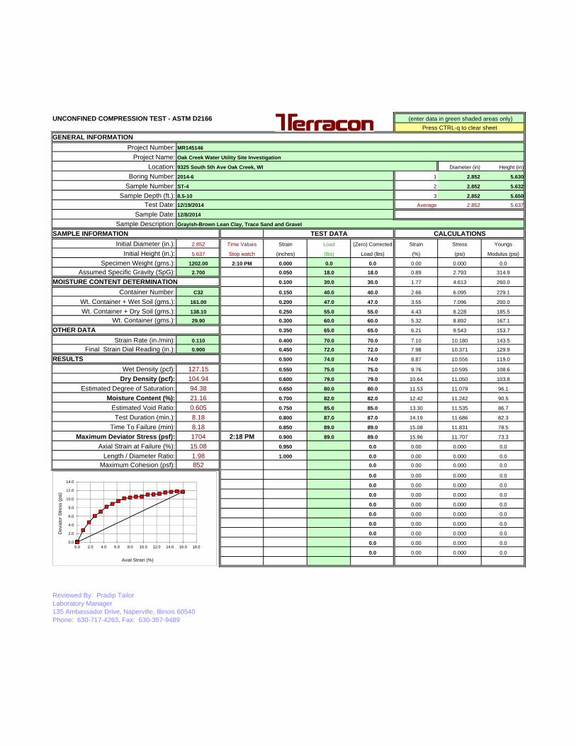
UNCONFINED COMPRESSION TEST - ASTM D2166
GENERAL INFORMATIONProject Number: MR145146
Project Name:Location: Diameter (in) Height (in)
Boring Number: 2014-6 1 2.852 5.630
Sample Number: ST-4 2 2.852 5.632
Sample Depth (ft.): 8.5-10 3 2.852 5.650Test Date: 12/19/2014 Average 2.852 5.637
Sample Date: 12/8/2014
Sample Description: Grayish-Brown Lean Clay, Trace Sand and Gravel
SAMPLE INFORMATION TEST DATA CALCULATIONSInitial Diameter (in.): 2.852 Time Values Strain Load (Zero) Corrected Strain Stress Youngs
Initial Height (in.): 5.637 Stop watch (inches) (lbs) Load (lbs) (%) (psi) Modulus (psi)
Specimen Weight (gms.): 1202.00 2:10 PM 0.000 0.0 0.0 0.00 0.000 0.0
Assumed Specific Gravity (SpG): 2.700 0.050 18.0 18.0 0.89 2.793 314.9
MOISTURE CONTENT DETERMINATION 0.100 30.0 30.0 1.77 4.613 260.0
Container Number: C32 0.150 40.0 40.0 2.66 6.095 229.1
Wt. Container + Wet Soil (gms.): 161.00 0.200 47.0 47.0 3.55 7.096 200.0
Wt. Container + Dry Soil (gms.): 138.10 0.250 55.0 55.0 4.43 8.228 185.5
Wt. Container (gms.): 29.90 0.300 60.0 60.0 5.32 8.892 167.1
OTHER DATA 0.350 65.0 65.0 6.21 9.543 153.7
Strain Rate (in./min): 0.110 0.400 70.0 70.0 7.10 10.180 143.5
Final Strain Dial Reading (in.): 0.900 0.450 72.0 72.0 7.98 10.371 129.9
RESULTS 0.500 74.0 74.0 8.87 10.556 119.0
Wet Density (pcf): 127.15 0.550 75.0 75.0 9.76 10.595 108.6
Dry Density (pcf): 104.94 0.600 79.0 79.0 10.64 11.050 103.8
Estimated Degree of Saturation: 94.38 0.650 80.0 80.0 11.53 11.079 96.1
Moisture Content (%): 21.16 0.700 82.0 82.0 12.42 11.242 90.5
Estimated Void Ratio: 0.605 0.750 85.0 85.0 13.30 11.535 86.7
Test Duration (min.): 8.18 0.800 87.0 87.0 14.19 11.686 82.3
Time To Failure (min): 8.18 0.850 89.0 89.0 15.08 11.831 78.5
Maximum Deviator Stress (psf): 1704 2:18 PM 0.900 89.0 89.0 15.96 11.707 73.3
Axial Strain at Failure (%): 15.08 0.950 0.0 0.00 0.000 0.0
Length / Diameter Ratio: 1.98 1.000 0.0 0.00 0.000 0.0
Maximum Cohesion (psf): 852 0.0 0.00 0.000 0.0
0.0 0.00 0.000 0.0
0.0 0.00 0.000 0.0
0.0 0.00 0.000 0.0
0.0 0.00 0.000 0.0
0.0 0.00 0.000 0.0
0.0 0.00 0.000 0.0
0.0 0.00 0.000 0.0
0.0 0.00 0.000 0.0
0.0 0.00 0.000 0.0
Reviewed By: Pradip TailorLaboratory Manager135 Ambassador Drive, Naperville, Illinois 60540Phone: 630-717-4263, Fax: 630-357-9489
(enter data in green shaded areas only)Press CTRL-q to clear sheet
Oak Creek Water Utility Site Investigation
9325 South 5th Ave Oak Creek, WI
0.0
2.0
4.0
6.0
8.0
10.0
12.0
14.0
0.0 2.0 4.0 6.0 8.0 10.0 12.0 14.0 16.0 18.0
Dev
iato
rStre
ss(p
si)
Axial Strain (%)

UNCONFINED COMPRESSION TEST - ASTM D2166
GENERAL INFORMATIONProject Number: MR145146
Project Name:Location: Diameter (in) Height (in)
Boring Number: 2014-6 1 2.847 5.605
Sample Number: ST-6 2 2.825 5.606
Sample Depth (ft.): 14-16 3 2.835 5.605Test Date: 12/22/2014 Average 2.836 5.605
Sample Date: 12/8/2014
Sample Description: Grayish-Brown Lean Clay, Trace Sand and Gravel
SAMPLE INFORMATION TEST DATA CALCULATIONSInitial Diameter (in.): 2.836 Time Values Strain Load (Zero) Corrected Strain Stress Youngs
Initial Height (in.): 5.605 Stop watch (inches) (lbs) Load (lbs) (%) (psi) Modulus (psi)
Specimen Weight (gms.): 1202.20 10:16 AM 0.000 0.0 0.0 0.00 0.000 0.0
Assumed Specific Gravity (SpG): 2.700 0.050 89.0 89.0 0.89 13.967 1565.8
MOISTURE CONTENT DETERMINATION 0.100 131.0 131.0 1.78 20.373 1142.0
Container Number: H3 0.150 158.0 158.0 2.68 24.349 909.9
Wt. Container + Wet Soil (gms.): 138.20 0.200 189.0 189.0 3.57 28.859 808.8
Wt. Container + Dry Soil (gms.): 122.10 0.250 201.0 201.0 4.46 30.408 681.8
Wt. Container (gms.): 30.40 0.300 211.0 211.0 5.35 31.622 590.8
OTHER DATA 0.350 214.0 214.0 6.24 31.770 508.8
Strain Rate (in./min): 0.110 0.400 218.0 218.0 7.14 32.056 449.2
Final Strain Dial Reading (in.): 0.900 0.450 226.0 226.0 8.03 32.913 410.0
RESULTS 0.500 233.0 233.0 8.92 33.603 376.7
Wet Density (pcf): 129.38 0.550 239.0 239.0 9.81 34.131 347.8
Dry Density (pcf): 110.05 0.600 245.0 245.0 10.70 34.642 323.6
Estimated Degree of Saturation: 89.29 0.650 250.0 250.0 11.60 34.995 301.8
Moisture Content (%): 17.56 0.700 255.0 255.0 12.49 35.335 283.0
Estimated Void Ratio: 0.531 0.750 260.0 260.0 13.38 35.661 266.5
Test Duration (min.): 8.18 0.800 265.0 265.0 14.27 35.972 252.0
Time To Failure (min): 8.18 0.850 270.0 270.0 15.16 36.270 239.2
Maximum Deviator Stress (psf): 5321 10:25 AM 0.900 278.0 278.0 16.06 36.952 230.1
Axial Strain at Failure (%): 16.06 0.950 0.0 0.00 0.000 0.0
Length / Diameter Ratio: 1.98 1.000 0.0 0.00 0.000 0.0
Maximum Cohesion (psf): 2661 0.0 0.00 0.000 0.0
0.0 0.00 0.000 0.0
0.0 0.00 0.000 0.0
0.0 0.00 0.000 0.0
0.0 0.00 0.000 0.0
0.0 0.00 0.000 0.0
0.0 0.00 0.000 0.0
0.0 0.00 0.000 0.0
0.0 0.00 0.000 0.0
0.0 0.00 0.000 0.0
Reviewed By: Pradip TailorLaboratory Manager135 Ambassador Drive, Naperville, Illinois 60540Phone: 630-717-4263, Fax: 630-357-9489
(enter data in green shaded areas only)Press CTRL-q to clear sheet
Oak Creek Water Utility Site Investigation
9325 South 5th Ave Oak Creek, WI
0.0
5.0
10.0
15.0
20.0
25.0
30.0
35.0
40.0
0.0 2.0 4.0 6.0 8.0 10.0 12.0 14.0 16.0 18.0
Dev
iato
rStre
ss(p
si)
Axial Strain (%)


40
50
60
70
80
900.0 1.0 2.0 3.0 4.0 5.0 6.0 7.0 8.0 9.0 10.0
400
500
600
700
800
900
in C
C
Pressure in TSF
ume
in C
C
Job Number: MR145146Boring No.: B-8PMTTest Depth: 18.0-20.5 Feet
Date: 2-24-15
Pl = 9.1- tsf
-10
0
10
20
30
40
-100
0
100
200
300
400
0.0 1.0 2.0 3.0 4.0 5.0 6.0 7.0 8.0 9.0 10.0
Cre
ep i
Inje
cted
Vol
Pressure in TSFVolumeCreepSeries3
Po = 1.5 tsf
Pf = 4.6 tsf
E+ = 169 tsf
Ed = 80 tsf

Pressuremeter Data Reduction (BX)
Job No.: MR145146Boring No.: B-8PMTTest Depth: Feet
Water Correction: 0.69 Bars
Corrected CorrectedNo. Pressure Inertia Corrected 30 Sec. 60 Sec. Creep 30 Sec. 60 Sec. Incremental
Readings Correction Pressure Volume Volume Volume Volume Modulus(bars) (bars) (tsf) (cc) (cc) (cc) (cc) (cc) (tsf)
1 0.00 0.03 0.7 8 12 4 7.3 11.22 0.50 0.13 1.1 48 52 4 47.0 51.0 163 1.00 0.21 1.5 84 87 3 82.8 85.8 214 2.00 0.28 2.5 123 123 0 121.4 121.4 475 3.00 0.31 3.5 143 143 0 140.9 140.9 916 4.00 0.34 4.5 163 163 0 160.6 160.6 947 4.50 0.36 5.0 180 180 0 177.4 177.4 558 5.00 0.39 5.5 200 200 0 197.2 197.2 489 5.50 0.43 6.0 225 225 0 222.1 222.1 39
10 2.50 0.39 2.9 200 200 0 198.2 198.2 25711 3.50 0.41 3.9 211 211 0 208.8 208.8 19112 4.50 0.42 5.0 222 222 0 219.4 219.4 19313 5.50 0.44 6.0 239 239 0 236.1 236.1 12414 6.00 0.47 6.5 254 259 5 250.9 255.9 52
18.0-20.5
14 6.00 0.47 6.5 254 259 5 250.9 255.9 5215 6.70 0.53 7.2 295 308 13 291.7 304.7 3016 7.00 0.57 7.4 332 348 16 328.7 344.6 1517 7.50 0.65 7.9 394 418 24 390.5 414.5 15
Ed= 80 TSF E+= 169 TSF Pl= 9.1 TSF
C:\Users\msccjw\AppData\Roaming\Microsoft\Excel\MR145146_OakCreek_PMT_Test (version 1).xls3/9/2015

50
60
70
80
900.0 2.0 4.0 6.0 8.0 10.0 12.0 14.0 16.0 18.0 20.0
500
600
700
800
900
in C
C
Pressure in TSF
olum
e in
CC
Job Number: MR145146Boring No.: B-8PMTTest Depth: 35.0-37.5 Feet
Date: 2-24-15
Pl = 19.2- tsf
-10
0
10
20
30
40
-100
0
100
200
300
400
0.0 2.0 4.0 6.0 8.0 10.0 12.0 14.0 16.0 18.0 20.0
Cre
ep
Inje
cted
Vo
Pressure in TSFVolumeCreepSeries3
Po = 2.6 tsf
Pf = 8.4 tsf
E+ = 243 tsf
Ed = 129 tsf
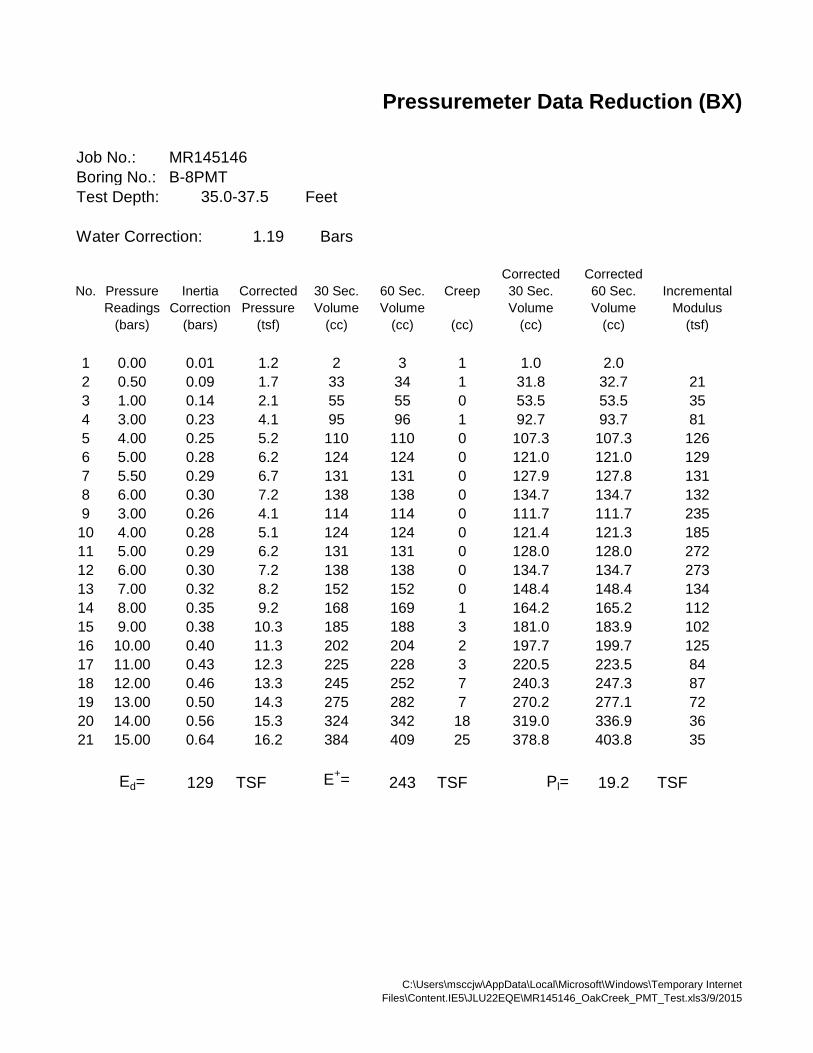
Pressuremeter Data Reduction (BX)
Job No.: MR145146Boring No.: B-8PMTTest Depth: Feet
Water Correction: 1.19 Bars
Corrected CorrectedNo. Pressure Inertia Corrected 30 Sec. 60 Sec. Creep 30 Sec. 60 Sec. Incremental
Readings Correction Pressure Volume Volume Volume Volume Modulus(bars) (bars) (tsf) (cc) (cc) (cc) (cc) (cc) (tsf)
1 0.00 0.01 1.2 2 3 1 1.0 2.02 0.50 0.09 1.7 33 34 1 31.8 32.7 213 1.00 0.14 2.1 55 55 0 53.5 53.5 354 3.00 0.23 4.1 95 96 1 92.7 93.7 815 4.00 0.25 5.2 110 110 0 107.3 107.3 1266 5.00 0.28 6.2 124 124 0 121.0 121.0 1297 5.50 0.29 6.7 131 131 0 127.9 127.8 1318 6.00 0.30 7.2 138 138 0 134.7 134.7 1329 3.00 0.26 4.1 114 114 0 111.7 111.7 235
10 4.00 0.28 5.1 124 124 0 121.4 121.3 18511 5.00 0.29 6.2 131 131 0 128.0 128.0 27212 6.00 0.30 7.2 138 138 0 134.7 134.7 27313 7.00 0.32 8.2 152 152 0 148.4 148.4 13414 8.00 0.35 9.2 168 169 1 164.2 165.2 112
35.0-37.5
14 8.00 0.35 9.2 168 169 1 164.2 165.2 11215 9.00 0.38 10.3 185 188 3 181.0 183.9 10216 10.00 0.40 11.3 202 204 2 197.7 199.7 12517 11.00 0.43 12.3 225 228 3 220.5 223.5 8418 12.00 0.46 13.3 245 252 7 240.3 247.3 8719 13.00 0.50 14.3 275 282 7 270.2 277.1 7220 14.00 0.56 15.3 324 342 18 319.0 336.9 3621 15.00 0.64 16.2 384 409 25 378.8 403.8 35
Ed= 129 TSF E+= 243 TSF Pl= 19.2 TSF
C:\Users\msccjw\AppData\Local\Microsoft\Windows\Temporary InternetFiles\Content.IE5\JLU22EQE\MR145146_OakCreek_PMT_Test.xls3/9/2015

40
50
60
70
80
900.0 5.0 10.0 15.0 20.0 25.0 30.0 35.0
400
500
600
700
800
900
in C
C
Pressure in TSF
ume
in C
C
Job Number: MR145146Boring No.: B-8PMTTest Depth: 50.0-52.5 Feet
Date: 2-24-15
Pl = 27.8- tsf
-10
0
10
20
30
40
-100
0
100
200
300
400
0.0 5.0 10.0 15.0 20.0 25.0 30.0 35.0
Cre
ep i
Inje
cted
Vol
Pressure in TSFVolumeCreepSeries3
Po = 3.0 tsf
Pf = 12.0 tsf
E+ = 464 tsf
Ed = 259 tsf

Pressuremeter Data Reduction (BX)
Job No.: MR145146Boring No.: B-8PMTTest Depth: Feet
Water Correction: 1.64 Bars
Corrected CorrectedNo. Pressure Inertia Corrected 30 Sec. 60 Sec. Creep 30 Sec. 60 Sec. Incremental
Readings Correction Pressure Volume Volume Volume Volume Modulus(bars) (bars) (tsf) (cc) (cc) (cc) (cc) (cc) (tsf)
1 0.50 0.19 2.0 65 76 11 63.6 74.62 1.00 0.26 2.5 100 112 12 98.4 110.4 213 1.50 0.28 3.0 125 125 0 123.2 123.2 684 2.00 0.29 3.5 134 134 0 132.0 131.9 1025 2.50 0.30 4.0 139 139 0 136.8 136.7 1916 3.00 0.31 4.5 144 144 0 141.6 141.6 1927 4.00 0.32 5.6 150 150 0 147.2 147.2 3318 5.00 0.33 6.6 157 157 0 153.9 153.9 2829 6.00 0.34 7.6 164 164 0 160.6 160.6 284
10 7.00 0.36 8.7 174 174 0 170.3 170.3 19711 8.00 0.37 9.7 184 184 0 180.1 180.1 19912 4.00 0.35 5.5 168 168 0 165.2 165.2 52613 6.00 0.36 7.6 177 177 0 173.6 173.6 46414 8.00 0.37 9.7 186 186 0 182.1 182.1 464
50.0-52.5
14 8.00 0.37 9.7 186 186 0 182.1 182.1 46415 9.00 0.39 10.7 197 197 0 192.9 192.8 18416 11.00 0.42 12.8 217 219 2 212.4 214.4 18717 13.00 0.45 14.8 239 242 3 234.1 237.0 18418 15.00 0.49 16.9 265 274 9 259.7 268.7 13619 17.00 0.54 18.9 306 317 11 300.4 311.3 10520 19.00 0.61 20.9 359 380 21 353.0 374.0 75
Ed= 259 TSF E+= 464 TSF Pl= 27.8 TSF
C:\Users\msccjw\AppData\Roaming\Microsoft\Excel\MR145146_OakCreek_PMT_Test (version 1).xls3/9/2015

Pressuremeter Data Reduction (BX)
40
50
60
70
80
900.0 5.0 10.0 15.0 20.0 25.0 30.0 35.0
400
500
600
700
800
900
in C
C
Pressure in TSF
olum
e in
CC
Job Number: MR145146Boring No.: B-8PMTTest Depth: 78.0-80.5 Feet
Date: 2-24-15
Pl = 32.8- tsf
-10
0
10
20
30
40
-100
0
100
200
300
400
0.0 5.0 10.0 15.0 20.0 25.0 30.0 35.0
Cre
ep
Inje
cted
Vo
Pressure in TSFVolumeCreepSeries3
Po = 4.0 tsf
Pf = 13.0 tsf
E+ = 678 tsf
Ed = 233 tsf
C:\Users\msccjw\AppData\Roaming\Microsoft\Excel\MR145146_OakCreek_PMT_Test (version 1).xls3/9/2015

Pressuremeter Data Reduction (BX)
Job No.: MR145146Boring No.: B-8PMTTest Depth: Feet
Water Correction: 2.48 Bars
Corrected CorrectedNo. Pressure Inertia Corrected 30 Sec. 60 Sec. Creep 30 Sec. 60 Sec. Incremental
Readings Correction Pressure Volume Volume Volume Volume Modulus(bars) (bars) (tsf) (cc) (cc) (cc) (cc) (cc) (tsf)
1 1.00 0.19 3.4 68 80 12 66.0 78.02 1.50 0.23 3.9 96 100 4 93.8 97.8 403 2.00 0.26 4.4 114 115 1 111.6 112.6 574 3.00 0.29 5.4 130 130 0 127.3 127.2 1215 4.00 0.31 6.4 144 144 0 140.9 140.9 1336 5.00 0.32 7.5 151 151 0 147.6 147.6 2787 6.00 0.33 8.5 158 158 0 154.4 154.4 2808 7.00 0.35 9.5 167 167 0 163.1 163.1 2179 8.00 0.36 10.6 176 176 0 171.9 171.9 220
10 9.00 0.37 11.6 186 186 0 181.7 181.6 19911 10.00 0.39 12.6 196 196 0 191.5 191.4 20212 4.00 0.36 6.4 178 178 0 175.0 174.9 72213 7.00 0.37 9.5 186 186 0 182.1 182.1 82714 10.00 0.39 12.6 198 198 0 193.5 193.4 529
78.0-80.5
14 10.00 0.39 12.6 198 198 0 193.5 193.4 52915 12.00 0.42 14.7 218 219 1 213.1 214.1 19616 14.00 0.44 16.7 236 238 2 230.7 232.7 22317 16.00 0.47 18.8 257 260 3 251.4 254.3 19718 19.00 0.52 21.9 290 300 10 283.9 293.8 16819 21.00 0.58 23.9 330 352 22 323.5 345.5 89
Ed= 233 TSF E+= 678 TSF Pl= 32.8 TSF
C:\Users\msccjw\AppData\Roaming\Microsoft\Excel\MR145146_OakCreek_PMT_Test (version 1).xls3/9/2015

APPENDIX C
SUPPORTING DOCUMENTS

< 20
Soil classification is based on the Unified Soil Classification System. Coarse Grained Soils have more than 50% of their dryweight retained on a #200 sieve; their principal descriptors are: boulders, cobbles, gravel or sand. Fine Grained Soils haveless than 50% of their dry weight retained on a #200 sieve; they are principally described as clays if they are plastic, andsilts if they are slightly plastic or non-plastic. Major constituents may be added as modifiers and minor constituents may beadded according to the relative proportions based on grain size. In addition to gradation, coarse-grained soils are definedon the basis of their in-place relative density and fine-grained soils on the basis of their consistency.
Plasticity Index
01 - 1011 - 30
> 30
RELATIVE PROPORTIONS OF FINES
Descriptive Term(s)of other constituents
Percent ofDry Weight
< 55 - 12> 12
TraceWithModifier
Water Level Aftera Specified Period of Time
GRAIN SIZE TERMINOLOGYRELATIVE PROPORTIONS OF SAND AND GRAVEL
TraceWithModifier
Exhibit C-1
WA
TE
R L
EV
EL
Auger
Shelby Tube
Loose
Medium Dense
Very Dense
10 - 29
4 - 9
19 - 58
500 to 1,000
less than 500
5 - 9
3 - 4
< 3
RingSamplerBlows/Ft.
8 - 15
< 30
30 - 49
> 119
PLASTICITY DESCRIPTION
Term
< 1515 - 29> 30
Descriptive Term(s)of other constituents
Water InitiallyEncountered
Water Level After aSpecified Period of Time
Major Componentof Sample
Percent ofDry Weight
LOCATION AND ELEVATION NOTES
RELATIVE DENSITY OF COARSE-GRAINEDSOILS
DescriptiveTerm
(Density)
RingSamplerBlows/Ft.
Dense
> 50
30 - 50
_ 4,000 to 8,000
> 30
15 - 30
> 42
19 - 42
(50% or more passing the No. 200 sieve.)Consistency determined by laboratory shear strength testing,
field visual-manual procedures or standard penetrationresistance
SA
MP
LIN
G
FIE
LD
TE
ST
S
(HP)
(T)
(b/f)
(PID)
(OVA)
DESCRIPTION OF SYMBOLS AND ABBREVIATIONS
Non-plasticLowMediumHigh
BouldersCobblesGravelSandSilt or Clay
Hand Penetrometer
Torvane
Standard PenetrationTest (blows per foot)
Photo-Ionization Detector
Organic Vapor Analyzer
Water levels indicated on the soil boringlogs are the levels measured in theborehole at the times indicated.Groundwater level variations will occurover time. In low permeability soils,accurate determination of groundwaterlevels is not possible with short termwater level observations.
DESCRIPTIVE SOIL CLASSIFICATION
Unless otherwise noted, Latitude and Longitude are approximately determined using a hand-held GPS device. The accuracyof such devices is variable. Surface elevation data annotated with +/- indicates that no actual topographical survey wasconducted to confirm the surface elevation. Instead, the surface elevation was approximately determined from topographicmaps of the area.
7 - 18
59 - 98
> 99
DescriptiveTerm
(Consistency)
2,000 to 4,000
1,000 to 2,000
10 - 18
CONSISTENCY OF FINE-GRAINED SOILS
Ring Sampler
Grab Sample
Split Spoon
Macro Core
Rock Core
No Recovery
Particle Size
Over 12 in. (300 mm)12 in. to 3 in. (300mm to 75mm)3 in. to #4 sieve (75mm to 4.75 mm)#4 to #200 sieve (4.75mm to 0.075mmPassing #200 sieve (0.075mm)
ST
RE
NG
TH
TE
RM
S
(More than 50% retained on No. 200 sieve.)Density determined by
Standard Penetration ResistanceIncludes gravels, sands and silts.
StandardPenetration or
N-ValueBlows/Ft.
0 - 6Very Loose 0 - 3 Very Soft
Soft
Medium-Stiff
Stiff
Very Stiff
Hard
UnconfinedCompressive
Strength,Qu, psf
2 - 4
0 - 1
StandardPenetration or
N-ValueBlows/Ft.
RingSamplerBlows/Ft.
50 - 89
90 - 119
20 - 29
50 - 79
>79
DescriptiveTerm
(Consistency)
StandardPenetration or
N-ValueBlows/Ft.
BEDROCK
Weathered
Firm
Medium Hard
Hard
Very Hard
30 - 49
> 8,000
4 - 8
GENERAL NOTES
Bid Questions and Answers – Oak Creek Water and Sewer Utility - Prestressed Concrete Storage Tank Pre-Selection April 27, 2015
1. Please provide the design overflow/draw down flow rate.
A: 30 million gallons per day.
2. The project drawings do not show any backfill around the tank. We estimate the frost depth in Wisconsin to be about 4’ to 5’. It appears that 4’ of backfill should be provided for frost protection. Please confirm the backfill depth is at least 4’.
A: The addition of berms to the side walls of the tank are not acceptable. See Drawings.
3. Drawing # 40-SD-301 shows a grout pad on top of the 6” concrete floor with the thickness of grout varying from 15” to 2” to develop the slope across the tank floor. It is our experience and opinion that the floor slope is best achieved by sloping the granular leveling base below the 6” floor, instead of using a grout topping. The grout topping, especially one15” thick, is likely to crack and may not have the required durability. We request that our alternative method of building the floor slope be permitted. Please clarify.
A: The grout is deleted. See revised drawings.
4. Sketch 0330-016 shows the underfloor pipe encasement tied to the tank floor with reinforcement. Our standard practice is to separate the pipe encasement from the tank floor by providing a construction joint. In order to reduce restraint shrinkage stresses and associated floor cracking, we use a 30 mil polyfilm on top of the pipe encasement before pouring the tank floor. No reinforcement is provided across this construction joint so as to permit movement of tank floor relative to the encasement. We request that this alternative method of design and construction of pipe encasement/floor, without any reinforcement in the encasement and across the construction joint, be permitted. Please clarify.
A: Tie the encasement to the floor slab. See revised drawings.
5. According to Section 1.03.F of the tank specs, a number of Design Loads and Foundation Criteria are to be found in the Structural Drawings. However, there were no structural drawings included in the bid package; and the drawings that are included pertain mostly to the baffle walls and exterior architectural treatment.
A: Drawings are in Addendum 1
6. Section 1.03C- The minimum reinforcement required is either 0.0025% or 0.12 square inches. For a 3” dome, 0.0025% is 0.09 square inches. We generally provide #3@12” which is 0.11<0.12. We request the section be changed to show 0.11 square inches instead of 0.12.
A: Leave as is.

7. Section 3.04J requires plastic wrapping wall after applying final coat. This is not a standard practice for Type III tanks and we request this requirement be removed for Type III tanks.
A: Leave as is.
8. 3.08A-Dome Curing – Our standard practice is to cure the dome with curing compound. We request this section be modified to include curing the dome with a curing compound.
A: Curing compound has been added. See revised specification.
9. As we discussed please include the project site drawing in an Addendum.
A: Included in Addendum 1.
10. Also we recommend removing the AWWA D110 Type I (cast-in-place wall) and Type II (shotcrete wall) from the specification as these tanks are typically not built in Wisconsin. In particular the Type II shotcrete wall tank is generally considered unacceptable in cold weather climates due to the possibility of freeze/thaw action which can cause delaminating of the shotcrete surfaces.
A: We will leave the spec as is, but the benefits of a Type 1 or 2 tank, if submitted, will be considered in the evaluation.
11. Bid Form, Page 3, Item 8. The Bid form date is specified as 2013. We believe this should read 2015. Please clarify.
A: New Bid Form included in Addendum 1.
12. There are minority percentages noted in the advertisement, but, nothing further mentioned in the specifications. Are minority percentages required for this project? Please clarify.
A: No minority percentages are required.
13. The Bid form is required to be submitted with 5 copies. Given the nature of this bid, can we submit one copy on bid day and then the low bidder submits the other four within 24 hours? Please clarify.
A: Addendum 1 modified to three (3) copies.
14. According to Table 3, Section 4.3 of the Geotechnical Report, the excavation elevation varies between 74’ and 84’, with a weighted average of 80’. We believe it advisable to excavate instead to a uniform elevation of about 80’ in order to ensure uniform support conditions under the entire tank footprint. Please clarify.
A: Required over-excavation is necessary to remove compressible materials from the zone of influence of the tank. The materials slated for removal must be adequately removed and backfilled. The contractor may elect to remove additional material to form a fill of uniform thickness.
15. Section 4.3 of the Geotechnical Report recommends a net allowable soil bearing pressure of 2,000 psf, which however, is not enough to design the tank foundations inasmuch as it is lower than the actual contact pressure under both the tank floor and

tank footing; and it is over conservative when considering that the tank will be founded on nearly 16 feet of select fill – which will in turn bear on substantially high-capacity subgrade. The attached sketch (Fig. 1) shows the actual contact pressures under the tank. Please note that to properly design the footing, we need nearly 3,000 psf. Can the footing be designed for 3,000 psf? Please clarify.
A: The attached geotechnical report was revised to reflect maximum allowable bearing pressure of 3,000 pounds per square foot (psf). The project documents will be modified to require select granular fill materials to allow for efficient dissipation of stresses in the vicinity of the tank foundation.
16. Subfooting clarification. Drawing 40-SD-103 shows 4’ of concrete fill under the tank footing. We recognize the 4-ft “concrete fill” is for frost protection, but we discourage this detail and instead recommends a “bermed” backfill as shown in the attached sketch (Fig. 1). Is a bermed backfill acceptable? Please clarify.
A: No. Site grading and hydraulic considerations make this undesirable.
17. The material for the baffle wall brace is not specified. Is it acceptable to use aluminum braces? Please clarify.
A: See Drawings in Addendum 1. 316 stainless steel is specified.
18. Please provide the invert elevation of all underfloor piping.
A: See revised drawings.
19. Drawing 40-SD-231 only shows an expansion joint for the 42” outlet pipe. Please clarify if an expansion joint is required for other underfloor piping such as inlet pipe, overflow pipe and drain.
A: See revised drawings.
20. Our normal practice in moderate to low seismic areas is to provide two flexible couplings, instead of expansion joints because of the anticipated movement under non-seismic loading is in the order of 3”+/- vertical and minimum along axis of the pipe as well as transverse direction. Accordingly, we recommend replacing one expansion joint with two flexible couplings. Is the acceptable? Please clarify.
A: See revised drawings.
21. Can you please confirm whether the tank construction will take place in spring/summer of 2016?
A: It is anticipated that the General Contractor can begin work in the first quarter of 2016. Exact timing of the tank construction will need to be determined between the General Contractor and Tank Supplier.
22. Can you please confirm the Tank Design drawings to be included with the Proposal shall be “Preliminary Design Drawings” and will not require a Professional Engineering Seal?
A: Correct.

23. Specification 00 11 57, pg. 9, Article 6.6.2 indicates by Signing the Bid Form the Supplier certifies that if selected the Supplier will sign the Agreement provided in the Request for Proposals and Statement of Qualifications. Can you please provide the Agreement for our review?
A: See Addendum 1 for modifications.
24. The Contract Documents discuss Liquidated Damages in several places. Can you please provide the Liquidated Damage amounts?
A: The liquidated damaged in the General (Installing) Contractors documents is currently $3,000 per day.
25. Can you please confirm that the Owner will provide all construction and testing water required for the project?
A: Yes, they will.
26. Specification 33 16 13.15, section 1.03.C indicates the tank roof must be a cast-in-place dome. Can you please confirm a precast dome is also acceptable?
A: Precast dome is not acceptable.
27. Specification 33 16 13.15, section 1.03.E - Generally penetrations are provided through the wall for overflow pipes and temporary construction access. We would recommend the specification be changed to allow for these wall penetrations.
A: The overflow pipe exits through the tank floor, as shown in the Drawings. Temporary construction access can be provided by Tank Supplier through the floor, but must be properly sealed afterwards.
28. Specification 33 16 13.15, section 1.03.F – Will you please provide the overflow rate for the proposed tank so the tank contractor can size the overflow weir appropriately?
A: 30 million gallons per day.
29. Specification 33 16 13.15, section 1.03.F – Please note we were unable to locate the snow load, wind load or maximum foundation bearing pressure on the structural drawings as indicated in this section. Can you please provide these design values?
A: See Addendum 1 Drawings.
30. Specification 33 16 13.15, section 1.05.A.2 does not appear to match the requirements of specification 00 11 57, section 6.4.2 with regards to the suppliers experience. Can you please confirm the requirements of 00 11 57, 6.4.2 are required for the proposal?
A: See Addendum 1 for revised specifications.
31. Specification 33 16 13.15, section 2.01 requires concrete be in accordance with section 03 30 00. Can you please confirm it will be acceptable for the tank contractors to submit their standard mix designs in lieu of the ones listed in section 03 30 00 for use in constructing the tank as long as the mix designs will achieve the strength and durability requirements specified?
A: No. Concrete mix designs will be evaluated during the submittal process.

32. Specification 33 16 13.15, section 2.01.B.3 – Please note, AWWA D110 requires a minimum 3,500 psi compressive strength for membrane floor systems. Can you please confirm the 3,500 psi floor concrete strength is acceptable for the tank floor?
A: Concrete strength for the floor slab is 4500 psi. See revised specification.
33. Specification 33 16 13.15, section 2.02.E – Please note AWWA D110 requires a minimum 4,500 psi compressive strength for shotcrete. Can you please confirm 4,500 psi strength shotcrete will be required? Additionally, we recommend ¼” polypropylene fibers be required for the shotcrete covercoat. Polypropylene fibers aid in controlling plastic shrinkage cracking and has proven to be very effective. Can you please confirm it is acceptable to utilize ¼” polypropylene fibers for the shotcrete covercoat?
A: Shotcrete compressive strength is 4500 psi. See revised specification. Yes polypropylene fibers may be added to the shotcrete.
34. Specification 33 16 13.15, section 2.04.A – Can you please confirm it will be acceptable to use grade 60 mild reinforcing bars and the allowable stresses should be in accordance with ACI 350 in lieu of the 18,000 psi outlined?
A: Yes. See revised specification.
35. Specification 33 16 13.15, section 2.05.D.3 – Please note AWWA D110 requires a minimum residual compression of 200 psi within the prestressed tank wall. Can you please confirm a 200 psi residual will be required in lieu of the 100 psi outlined within this section?
A: 100 psi has been changed to 200 psi. See revised specification.
36. Specification 33 16 13.15, section 2.07, please note ASTM A366 has been withdrawn and updated to ASTM A1008. Can you please confirm steel diaphragm should be in accordance with ASTM A1008?
A: A366 has been changed to A1008. See revised specification.
37. Specification 33 16 13.15, section 2.09.C.2 requires a stainless steel hatch. Can you please confirm that an aluminum hatch would be acceptable in lieu of the stainless steel hatch, which will be significantly higher in cost? We have quite a long, successful history using aluminum hatches with excellent results.
A: The specification is not changed, but an aluminum hatch can be proposed as a cost saving alternative in your proposal.
38. Specification 33 16 13.15, section 3.02.A requires the corewall to achieve a compressive strength of 4,000 psi or higher prior to beginning prestressing. AWWA D110 allows the prestressing operation to begin after the corewall has attained a strength of at least 1.8 times the stress being applied. Can you please confirm prestressing operations can begin once the corewall and dome have achieved a stress greater than 1.8 of that being applied?
A: Prestressing may begin at a concrete compressive strength of 4000 psi as the specification states.

39. Specification 33 16 13.15, section 3.03.D requires the minimum spacing to be 3/8 inches or 1.5 unit diameters whichever is larger as well as limits the number of wires per foot to 22. Can you please confirm the minimum spacing can be 5/16 inches or 1.5 unit diameters in accordance with AWWA D110 and allow 24 wires per foot on this project?
A: The minimum spacing has been changed to 5/16” or 1.5 unit diameters, with a maximum of 24 wires per foot.
40. Specification 33 16 13.15, section 3.04.B requires the prestressing to applied from the bottom to the top of the wall. Can you please confirm the tank contractor can begin applying prestressing from the top to the bottom of the tank wall at their option?
A: This paragraph is referring to the progression of shotcreting and not prestressing.
41. Specification 33 16 13.15, section 3.04.J requires plastic sheeting upon final application of shotcrete to maintain moisture for curing. Can you please confirm if water methods of curing at the contractors’ option as an alternative to plastic sheeting and as allowed in AWWA D110?
A: Plastic sheeting is required.
42. Can you please confirm the following concrete finishes for the prestressed tank will be acceptable for this project:
Fresno Finish for the tank floor slab
Light broom finish for the interior of the precast wall panels
Light broom finish for the exterior of the dome with a form finish on the interior of the dome
Exterior shotcrete shall receive a natural gun/nozzle finish.
A: Yes.
43. Specification 33 16 13.15, section 3.08.A requires the dome to be water cured for 7 days and scheduling wire wrapping and application of shotcrete so curing is not interrupted and water from curing shall not wash or damage shotcrete wire coats. Can you please confirm if curing compounds can be used in lieu of water curing the dome? This will allow for more efficient construction schedule on the project and has been Industry standard for several decades.
A: Curing compound has been added as an alternative. See revised specification.
44. Drawing 40-SD-301, we have concerns that the grout topping will restrict the tank wall movement and induce additional stresses into the tank wall and would like to discuss with you other means of accomplishing the desired drainage of the tank floor.
A: See Drawings in Addendum 1.
45. Can you please provide the centerline elevation of all the under slab piping?
A: See revised Drawings in Addendum 1.
46. We recommend fully concrete encasing the under slab piping up to the underside of the tank concrete floor/foundation. Can you please confirm this will be acceptable?

A: Yes this is acceptable.
47. Drawing 40-A-241 depicts the hatch and interior ladder aligned with the straight baffle wall. Can you please confirm it would be acceptable to install the hatch and ladder radial to the tank and connect the interior ladder to the tank wall?
48. Can you please confirm the required length of the straight precast baffle walls?
A: See Drawing 40-A-231.
49. Please note the allowable bearing capacity of 2.0 ksf listed on page 11 of the Subsurface Exploration and Geotechnical Engineering Analyses memorandum dated March 18th, 2015 is less than even the liquid column load indicated on page 1 of the memorandum. This does not take into account the structure dead load; indicating the soils may not provide adequate support for the tank. Can you please provide additional recommendations to improve the allowable bearing capacity to a minimum 3 ksf for this project or discuss with the geotechnical engineer this information for his input on how this should be resolved?
A: The attached geotechnical report was revised to reflect maximum allowable bearing pressure of 3,000 pounds per square foot (psf). The project documents will be modified to require select granular fill materials to allow for efficient dissipation of stresses in the vicinity of the tank foundation.

OAK CREEK WATER AND SEWER UTILITY PRESTRESSED CONCRETE STORAGE TANK
BIDDER’S NAME __________________________________________________________ PW/DEN001/653463 BID FORM APRIL 27, 2015 00 41 13 - 1 ©COPYRIGHT 2015 CH2M HILL
NOTE TO BIDDER: Use typewriter or BLACK ink for completing this Bid Form.
BID FORM
To: Oak Creek Water and Sewer Utility (Owner)
Mailing Address: Attn: Ron J. Pritzlaff, P.E., Utility Engineer Oak Creek Water and Sewer Utility 170 West Drexel Avenue Oak Creek, WI 53154
Project Identification: Prestressed Concrete Storage Tank for the Oak Creek Water and Sewer Utility
2016 Water Treatment Plant Improvements Project
1. BIDDER'S DECLARATION AND UNDERSTANDING
1.1. This Bid is genuine and not made in the interest of or on behalf of any undisclosed person, firm, or corporation and is not submitted in conformity with any agreement or rules of any group, association, organization, or corporation; Bidder has not directly or indirectly induced or solicited any other Bidder to submit a false or sham Bid; Bidder has not solicited or induced any person, firm, or corporation to refrain from bidding; and Bidder has not sought by collusion to obtain for itself any advantage over any other Bidder or over the Utility.
1.2. In submitting this Bid, Bidder certifies Bidder is qualified to do business in the State of Wisconsin as required by laws, rules, and regulations at the time the Bid Form is submitted to the Utility.
1.3. The undersigned Bidder understands and agrees that this Proposal shall form the basis for a subcontract with the Installing Contractor that is selected by the Owner. Therefore, the undersigned agrees to enter into an agreement to perform and furnish all Work as specified or indicated in these Specifications for the amount indicated in this Bid Form and in accordance with the other terms and conditions of this Request for Proposal and Statement of Qualifications.
1.4. The undersigned accepts all of the terms and conditions of this Request for Proposals and Statement of Qualifications including, without limitation, those dealing with the disposition of Bid security, and the penalties that may be imposed based on results from the Performance Testing. This Proposal shall remain subject to acceptance for a period of 90 days after the day of Bid opening.

OAK CREEK WATER AND SEWER UTILITY PRESTRESSED CONCRETE STORAGE TANK
BIDDER’S NAME __________________________________________________________ BID FORM PW/DEN001/653463 00 41 13 - 2 APRIL 27, 2015 ©COPYRIGHT 2015 CH2M HILL
1.5. The Bidder understands and agrees that the Owner may assign all of its rights and obligations under these Contract Documents to the Installing Contractor for the installation of the prestressed concrete storage tank.
1.6. The Bid Price of the selected Supplier will be assigned by the Owner to the Installing Contractor.
1.7. Notwithstanding this assignment, the guarantees and warranties specified in the Contract Documents are intended for the benefit of the Owner and the Installing Contractor, and may be enforced by either party.
2. CONTRACT EXECUTION
2.1. The undersigned Bidder agrees, if this Bid is accepted, to enter into an Agreement with the Installing Contractor to perform and furnish Work as specified or indicated in the Bidding Documents for the Contract Price derived from the Bid, and in accordance with the other terms and conditions of the Bidding Documents.
2.2. Bidder accepts the terms and conditions of the Bidding Documents.
3. INSURANCE
3.1. Bidder further agrees that the Bid amount(s) stated herein includes specific consideration for the specified insurance coverages.
4. ADDENDA
4.1. Bidder hereby acknowledges that it has received Addenda
Nos. , , , ,
(Bidder shall insert number of each Addendum received) and agrees that Addenda issued are hereby made part of the Bidding Documents, and Bidder further agrees that this Bid includes impacts resulting from said Addenda.
5. STATE AND LOCAL SALES AND USE TAXES
5.1. Taxes shall not be included in this Bid Form.
6. BID SCHEDULE
6.1. Bidders shall use only the Bid Schedule provided. All blank spaces in the Bid Schedule must be filled in, preferably in BLACK ink, in both words and figures where required. No

OAK CREEK WATER AND SEWER UTILITY PRESTRESSED CONCRETE STORAGE TANK
BIDDER’S NAME __________________________________________________________ PW/DEN001/653463 BID FORM APRIL 27, 2015 00 41 13 - 3 ©COPYRIGHT 2015 CH2M HILL
changes shall be made in the phraseology of the forms. Written amounts shall govern in case of discrepancy between the amounts stated in writing and the amounts stated in figures.
6.2. Prices quoted shall be f.o.b. with freight and full insurance paid by Bidder, to the Oak Creek Water and Sewer Utility Water Treatment Plant, 9325 S. 5th Avenue, Oak Creek, WI 53154.
6.3. Bidder shall provide required information by filling in all blanks following the Bid Schedule.
6.1. Bidder shall complete the Work in accordance with the Contract Documents for the following price(s):
6.1.1. Lump Sum Bid Price:
Dollars (words)
and Cents $ (numerals)
7. SURETY
7.1. If Bidder is awarded the Work from this Bid, the surety providing the Performance Bond is:
whose address is
Street City State Zip
8. BIDDER
SUBMITTED on , 2015.
State Contractor License No. . (If applicable)
If Bidder is:
An Individual
Name (typed or printed): By (signature):

OAK CREEK WATER AND SEWER UTILITY PRESTRESSED CONCRETE STORAGE TANK
BIDDER’S NAME __________________________________________________________ BID FORM PW/DEN001/653463 00 41 13 - 4 APRIL 27, 2015 ©COPYRIGHT 2015 CH2M HILL
Doing business as:
Business address:
Phone No.: FAX No.:
A Partnership
Partnership Name: (SEAL) By:
(Signature of general partner – attach evidence of authority to sign)
Name (typed or printed): Business address:
Phone No.: FAX No.:
A Corporation
Corporation Name: (SEAL) State of Incorporation: Type (General Business, Professional, Service, Limited Liability): By:
(Signature – attach evidence of authority to sign)
Name (typed or printed): Title: (CORPORATE SEAL)
Attest: (Signature of Corporate Secretary)
Business address:
Phone No.: FAX No.:

OAK CREEK WATER AND SEWER UTILITY PRESTRESSED CONCRETE STORAGE TANK
BIDDER’S NAME __________________________________________________________ PW/DEN001/653463 BID FORM APRIL 27, 2015 00 41 13 - 5 ©COPYRIGHT 2015 CH2M HILL
Date of Qualification to do business is:
A Joint Venture
Joint Venturer Name: (SEAL) By:
(Signature of joint venture partner – attach evidence of authority to sign)
Name (typed or printed): Title:
Business address:
Phone No.: FAX No.:
(Each joint venturer must sign. The manner of signing for each individual, partnership, and corporation that is a party to the joint venture should be in the manner indicated above.)
Phone and FAX Number, and Address for receipt of official communications:
END OF SECTION

OAK CREEK WATER AND SEWER UTILITY PRESTRESSED CONCRETE STORAGE TANK
SECTION 33 16 13.15 PRESTRESSED CONCRETE TANK
PART 1 GENERAL
1.01 REFERENCES
A. The following is a list of standards which may be referenced in this section:
1. American Ladder Institute (ALI): A14.3, Ladders - Fixed - Safety Requirements.
2. American Concrete Institute (ACI): a. 506R, Guide to Shotcrete. b. 506.2, Specification for Shotcrete. b.c. 350-06, Code Requirements for Environmental Engineering
Concrete Structures and Commentary. c.d. 372R-13, Guide to Design and Construction of Circular Wire- and
Strand-Wrapped Prestressed Concrete Structures. 3. ASTM International (ASTM):
a. A82, Standard Specification for Steel Wire, Plain, for Concrete Reinforcement.
b. A185, Standard Specification for Steel Welded Wire Fabric, Plain, for Concrete Reinforcement.
c. A366, Standard Specification for Commercial Steel (CS) Sheet, Carbon, (0.15 Maximum Percent) Cold-Rolled.
d.c. A615, Standard Specification for Deformed and Plain Billet-Steel Bars for Concrete Reinforcement.
d. A666, Standard Specification for Annealed or Cold-Worked Austenitic Stainless Steel Sheet, Strip, Plate, and Flat Bar.
e. A1008, Standar Specification for Steel, Sheet, Cold-Rolled, Carbon, Structural, High-Strength Low-Alloy, High-Strength Low-Alloy with Improved Formability, Solution Hardened, and Bake Hardenable.
f. C42, Standard Test Method for Obtaining and Testing Drilled Cores and Sawed Beams of Concrete.
g. C144, Standard Specification for Aggregate for Masonry Mortar. h. C150, Standard Specification for Portland Cement. i. C207, Standard Specification for Hydrated Lime for Masonry
Purposes. j. C216, Standard Specification for Facing Brick (Solid Masonry
Units Made from Clay or Shale). k. C270, Standard Specification for Mortar for Unit Masonry. l. C920, Standard Specification for Elastomeric Joint Sealants.
PW/DEN001/653463 PRESTRESSED CONCRETE TANK APRIL 27, 2015 33 16 13.15 - 1 ©COPYRIGHT 2015 CH2M HILL

OAK CREEK WATER AND SEWER UTILITY PRESTRESSED CONCRETE STORAGE TANK
m. D1056, Standard Specification for Flexible Cellular Materials – Sponge or Expanded Rubber.
4. American Water Works Association (AWWA): D110-13, Wire- and Strand-Wound, Circular, Prestressed Concrete Water Tanks.
5. Federal Specifications: FS TT-P-0035 (1), Paint, Cementitious, Powder, White and Colors (for Interior and Exterior Use).
6. NSF International (NSF): NSF/ANSI 61, Drinking Water System Components - Health Effects.
7. Occupational Safety and Health Administration (OSHA): 29 CFR 1910.27, Fixed Ladders.
8. Precast/Prestressed Concrete Institute (PCI): MNL-120, PCI Design Handbook-Precast and Prestressed Concrete.
9. Sheet Metal and Air Conditioning Contractors National Association (SMACNA): 1793, Architectural Sheet Metal Manual.
10. Wisconsin Department of Natural Resources (WDNR): Wisconsin Administrative Code Chapter NR 811.
1.02 DEFINITIONS
A. Prestressed Tank System: Consists of a cast-in-place concrete floor slab, a core wall, baffle walls, and roof.
B. Shotcrete: Mortar projected directly upon intended surface.
1.03 DESIGN REQUIREMENTS
A. Obtain services of a qualified design engineer, as defined in Article Quality Assurance, to design Prestressed Tank System in accordance with AWWA D110-13 and other conforming to attributes specified in this section.
B. Floor Slab: Cast-in-place concrete, minimum reinforcing in slab equals 0.005 times concrete section.
C. Roof: Cast-in-place concrete dome with minimum thickness of 3 inches and minimum reinforcing of 0.0025 times concrete section with a minimum area of reinforcing steel each way equal to 0.120 inch squared.
D. Exterior Walls: Cast-in-place concrete core wall with plastic water stops at construction joints or shotcrete core wall with continuous internal steel diaphragm or precast concrete core wall with steel diaphragm, vertical joint seals, and shotcrete coverings. Walls placed on elastomeric bearing pads, free to move radially, and plastic water stop connection between wall and footing. Satisfy allowable stress requirements when calculating wall thicknesses.
PRESTRESSED CONCRETE TANK PW/DEN001/653463 33 16 13.15 - 2 APRIL 27, 2015 ©COPYRIGHT 2015 CH2M HILL

OAK CREEK WATER AND SEWER UTILITY PRESTRESSED CONCRETE STORAGE TANK
E. Baffle Walls: Precast concrete, laterally braced with diagonal braces attached to baffle wall and tank floor. Baffle walls and diagonal bracing shall be designed to resist seismic forces.
D.
E.F. Openings and Penetrations: Except for access manholes, other openings or penetrations through wall not permitted. Pipe penetrations shall be through floor slab and under footings. Pipe sleeves are allowed through footing for shotcrete equipment.
F.G. Design Loads and Foundation Criteria:
1. Dead Loads: Self Weight. 2. Roof Live Load: 20 psf for dome roof. 3. Snow Load: See structural drawings. 4. Wind Load: See structural drawings. 5. Differential Drying Allowance: 10 degrees F shall be additive to
temperature differential during winter. 6. Maximum Foundation Bearing Pressure: See structural drawings. 7. Maximum Differential Settlement: See geotechnical report. 8. Seismic Design Criteria: See structural drawings.
1.04 SUBMITTALS
A. Action Submittals:
1. Shop Drawings: a. Design Data:
1) Proposed details, concepts, stress calculations, and manhole opening for prestressed tank walls.
2) For design loads and foundation criteria, show calculations and details based on the seismic forces.
3) Details of vertical post-tensioning system. 4) Details for sealing vertical joints of steel diaphragm shell. 5) Details of prestressed tank accessories. 6) Calculations stamped by professional engineer registered in
the state of Wisconsin.Details of baffle walls and bracing. 7) Design drawings stamped by a professional engineer.
b. Curing methods for dome concrete. c. Description of construction method and materials. d. Manufacturer’s literature showing compliance with specification.
2. Samples: Vertical joint of steel diaphragm shell together with integral pumped epoxy material or other approved method to show evidence of satisfactory seal.
Formatted: Indent: Left: 0.6", Hanging: 0.4", No bullets ornumbering
PW/DEN001/653463 PRESTRESSED CONCRETE TANK APRIL 27, 2015 33 16 13.15 - 3 ©COPYRIGHT 2015 CH2M HILL

OAK CREEK WATER AND SEWER UTILITY PRESTRESSED CONCRETE STORAGE TANK
B. Informational Submittals:
1. Manufacturer’s Certificate of Compliance, in accordance with Section 01 61 00, Common Product Requirements: a. Shotcrete sand. b. Concrete and shotcrete admixtures do not contain chlorides or
other corrosive chemicals. c. Vertical Post-Tensioning System: Manufacturer’s load strain
curves certifying physical properties of steel and standard test data that components of anchorage units conform to specified requirements.
2. Manufacturer’s Certificate of Proper Installation, in accordance with Section 01 43 33, Manufacturers’ Field Services.
3. Certificates of Inspection: Vertical post-tensioning units have been inspected prior to shipment and contain no apparent defects.
4. Statements of Qualification: a. Registered professional engineer registered in the state of
Wisconsin. b. Prestressed tank installer.
5. Calculations stamped by a professional engineer registered in the state of Wisconsin.
5.6. Written Test Reports of Each Test and Inspection: a. Shotcrete. b. Mill test data of chemical composition for vertical post-tensioning
system. c. Test reports for prestressing steel components. d. Mill test data for circumferential prestressing material regardless
of manufacture. Include chemical composition, physical properties, and dimensions of steel prior to galvanizing. Mill test data for at least three samples of final prestressing material taken from material delivered to Site. Identify each roll that Samples were taken from. Identify packages or rolls of prestressing material with mill and heat number.
1.05 QUALITY ASSURANCE
A. Qualifications:
1. Qualified Design Engineer: Registered in the state of Project. 2. Prestressed Tank Installer: Company specializing in design and
construction of prestressed tanks. Minimum 205 years’ experience on tanks of similar size (1.5MG to 32.5MG) and type required for Project. Company has designed and built no less than twenty five comparable prestressed (wire or strand wrapped) tanks now in use and are giving
PRESTRESSED CONCRETE TANK PW/DEN001/653463 33 16 13.15 - 4 APRIL 27, 2015 ©COPYRIGHT 2015 CH2M HILL

OAK CREEK WATER AND SEWER UTILITY PRESTRESSED CONCRETE STORAGE TANK
satisfactory service. Tanks shall have been constructed within the last 5 10 years. Include name, address, and phone number of owners with proposal.
B. Shotcrete Panel Mockups:
1. When not using automated equipment, assemble test panel at least 30 inches by 30 inches for each mix being considered.
2. Assemble test panels to same thickness as structure, but not less than 3 inches.
3. Take minimum three cubes or cores from panels for strength testing of shotcrete.
4. Cut or broken surfaces shall be dense and free from laminations and sand pockets.
5. Retain and maintain test panels during construction to establish standards by which completed shotcrete Work will be judged.
6. Independent Testing Laboratory Services will: a. Test proposed materials, including water. b. Test proposed mix proportions. c. Test specimens. d. Secure production samples of materials at plants or stockpiles
during construction and test. e. Test strength of shotcrete as Work progresses.
1.06 DELIVERY, STORAGE, AND HANDLING
A. Materials delivered prior to time required, store in a dry, ventilated building, heat if necessary to prevent accumulation of moisture on materials or in wrapping. Do not store on ground or expose to weather.
B. Do not bend vertical post-tensioning bars during handling and storage. Replace bent bars, bars with surface damage, and bars with excessive rusting.
1.07 ENVIRONMENTAL REQUIREMENTS
A. Delay Work under the following conditions:
1. During high winds, when shotcreting, which may cause sand to separate at the nozzle.
2. When placing concrete, or shotcrete, as weather approaches freezing defined as below 40 degrees F when temperature is falling, or until temperature is 35 degrees F when temperature is rising.
3. During rains of high intensity which can wash cement out of fresh material.
PW/DEN001/653463 PRESTRESSED CONCRETE TANK APRIL 27, 2015 33 16 13.15 - 5 ©COPYRIGHT 2015 CH2M HILL

OAK CREEK WATER AND SEWER UTILITY PRESTRESSED CONCRETE STORAGE TANK
B. Cold Weather: Take precautions to avoid low temperatures detrimental to epoxy grout or the ability to pump. If grouting procedure cannot be postponed, keep wall temperatures within the required temperature range.
C. Hot Weather: When temperatures exceed 90 degrees F, obtain approval for method used to protect shotcrete from excessive heat and drying.
D. Do not expose circumferential prestressing on walls to weather for more than 72 hours. Exercise precautions during adverse weather conditions.
PART 2 PRODUCTS
2.01 CONCRETE
A. In accordance with Section 03 30 00, Cast-in-Place Concrete, except that a 3/8-inch maximum size aggregate may be used for dome concrete if designed for strength and maximum density.
B. Minimum Design (28 day) Strengths:
1. Dome Roof: 4,0500 psi (Class 4500F2S1P1C1). 2. Core Wall: 4,0500 psi (Class 4500F2S1P1C1). 3. Floor Slab: 34,0500 psi (Class 4500F2S1P1C1).
C. Admixtures: As specified in Section 03 30 00, Cast-in-Place Concrete.
2.02 SHOTCRETE
A. Fine Aggregates (Sand):
1. Saturated, surface dry, hard, dense, uncoated rock fragments free from injurious amounts of foreign or deleterious substances as specified in Section 03 30 00, Cast-in-Place Concrete.
2. Fineness Modulus for Sand: Range from 2.70 to 3.00 with maximum particle size of 1/4 inch.
3. Maintain sand at 3 to 6 percent moisture content; dampen or dry with sand dryers if necessary.
4. Gradation:
Sieve Size Percent Passing by Weight
No. 4 97 - 100
No. 8 90 - 98
No. 16 70 - 85
PRESTRESSED CONCRETE TANK PW/DEN001/653463 33 16 13.15 - 6 APRIL 27, 2015 ©COPYRIGHT 2015 CH2M HILL

OAK CREEK WATER AND SEWER UTILITY PRESTRESSED CONCRETE STORAGE TANK
Sieve Size Percent Passing by Weight
No. 30 35 - 55
No. 50 12 - 25
No. 100 2 - 8
B. Screen sand for finish coat to produce uniform dense surface in texture and appearance.
C. Water and Cement: As specified in Section 03 30 00, Cast-in-Place Concrete.
D. Admixtures: As specified in Section 03 30 00, Cast-in-Place Concrete.
E. Minimum design (28 day) strength 4,0500 psi.
2.03 WELDED WIRE FABRIC
A. In accordance with ASTM A82 and ASTM A185.
2.04 MILD STEEL REINFORCING
A. Deformed Grade 40 bars with maximum service load design, allowable stress of 18,000 psi in accordance with ASTM A615.bars, Grade 60 in accordance with ASTM A615. Allowable stresses in accordance with ACI 350.
2.05 CIRCUMFERENTIAL PRESTRESSING STEEL
A. High Tensile Wire:
1. Diameter Tolerance of Wire: Plus or minus 0.002 inch. 2. Tensile Strength: Minimum 210,000 psi. 3. Yield Strength at 1 Percent Extension: Minimum 170,000 psi. 4. Elongation in 10 Inches at Fracture: Minimum 4 percent. 5. Bending (R equals 5D): Minimum 6 bends per 90 degrees.
B. Hot-Dipped Galvanized Seven-Wire Continuous Strand:
1. Strand Diameter Tolerance: Plus or minus 1/32 inch. 2. Pitch: 12-16 (strand diameter). 3. Tensile Strength: Minimum 240,000 psi. 4. Yield Strength at 1 Percent Extension: Minimum 180,000 psi. 5. Elongation in 24-inch fracture minimum 4.5 percent. 6. Zinc Coating Weight: Minimum 0.75 ounce per square foot.
PW/DEN001/653463 PRESTRESSED CONCRETE TANK APRIL 27, 2015 33 16 13.15 - 7 ©COPYRIGHT 2015 CH2M HILL

OAK CREEK WATER AND SEWER UTILITY PRESTRESSED CONCRETE STORAGE TANK
C. Anchorage: Prestressing manufacturer’s standard and capable of safely developing full strength of units, and not susceptible to galvanic action with prestressed steel.
D. Prestressing Steel Requirements:
1. Initial prestress force in circumferential prestressing units after anchoring shall not exceed 70 percent of guaranteed ultimate strength. Coordinate value with tolerance requirements and reflect values in calculations.
2. Final prestress force in circumferential prestressing units, when using nonelectronic or electronic wrapping machine, not capable of close stress tolerance, shall be determined by using stress loss of 25,000 psi for concrete shrinkage, plastic flow, and creep in steel plus 6 percent of initial wire stress system tolerances.
3. Calculate final circumferential prestress force and location on wall. Final prestress force shall provide for minimum residual compression in wall, above that required to resist internal water pressure of 2100 psi. Maximum compression in core wall limited to 0.45 times design strength of core wall when using final prestress force after all losses. Maximum initial compression in core wall limited to 0.55 times design strength of core wall. Calculate wall thickness to comply with these requirements and bending requirements.
2.06 VERTICAL TENDONS
A. Solid High Strength Alloy Steel Bar:
1. Minimum Ultimate Tensile Strength: 145,000 psi. 2. Minimum Yield Stress at 0.2 Percent Offset: 125,000 psi. 3. Approximate Modulus of Elasticity: 30,000,000 psi. 4. Minus Elongation in 20 Diameters After Rupture: 4 percent. 5. Minimum Reduction of Area After Rupture: 20 percent.
B. Tendon Ducts:
1. Rigid galvanized metallic sheath or tubing or PVC pipe. 2. Sufficient strength to maintain its shape under potential forces created
during handling, placing, and vibrating of concrete. 3. Inside diameter of grout and vent pipe 3/8 inch larger than diameter of
vertical tendon.
C. Anchorage:
PRESTRESSED CONCRETE TANK PW/DEN001/653463 33 16 13.15 - 8 APRIL 27, 2015 ©COPYRIGHT 2015 CH2M HILL

OAK CREEK WATER AND SEWER UTILITY PRESTRESSED CONCRETE STORAGE TANK
1. Furnish anchor plates of steel to dimensions which will show no permanent physical distortion when tested with a unit of size required, together with standard anchorage devices, and to 100 percent of ultimate tensile strength of unit.
2. Size plate so concrete stresses shall meet allowable concrete bearing stresses in accordance with PCI MNL-120.
2.07 STEEL DIAPHRAGM SHELL
A. Tank diaphragm in accordance with ASTM A1008366 for Commercial Quality cold-rolled steel sheet. Minimum of 26-gauge sheet and form corrugations of a pattern to form a continuous positive watertight seal and a strong mechanical key between shotcrete and steel. Furnish steel sheets in one continuous length to full height of wall. Vertical joints between sheets.
2.08 SHOTCRETE MIX PROPORTIONS
A. Adjacent to Steel Diaphragm and Over Wires: 1 part cement to 3 parts sand.
B. All Other: 1 part cement to 4 parts sand.
2.09 ACCESSORIES
A. Manway:
1. Liquid tight quick-opening manway that opens into drinking water storage tank, anchored into tank per manway manufacturer’s recommendations.
2. Material: Type 316 stainless steel. 3. Size: 48 inch clear opening with 55 inch outside diameter. 4. Gasket: EPDM gasket all around manway hatch. 5. Hardware: Heavy-duty stainless steel hinges and handwheel release
mechanism. 6. Lock: Provide keyed cut resistant padlock to prevent entry. 7. Paint: Paint exterior of manway to match tank wall color. 8. Manufacturer and Model: Chase Associated, Inc.; CM-1.
B. Vent:
1. Mushroom cap vent with an automatically resetting pressure-vacuum relief frost proof mechanism in accordance with WDNR NR 811.
2. Material: Type 316 stainless steel. 3. Size: 24 inch diameter vent pipe with a 50 inch diameter dome. 4. Screen: 16x16 removable stainless steel screen. The skirted sides of
mushroom cap shall totally cover screens from view from side.
PW/DEN001/653463 PRESTRESSED CONCRETE TANK APRIL 27, 2015 33 16 13.15 - 9 ©COPYRIGHT 2015 CH2M HILL

OAK CREEK WATER AND SEWER UTILITY PRESTRESSED CONCRETE STORAGE TANK
5. Lock: Provide keyed padlock to prevent entry. 6. Paint: Paint exterior of manway to match tank roof color. 7. Manufacturer: Omega Vent Security Shroud.
C. Hatch with Safety Chains and Posts:
1. Roof hatch mounted to concrete curb with watertight cover which overlaps the framed opening and extends down around the frame a minimum of 2 inches in accordance with WDNR NR 811.
2. Material: Type 316 stainless steel. 3. Size: 48 inch by 48 inch. 4. Gasket: EPDM gasket between hatch frame and concrete curb and
between roof hatch and frame, all around. 5. Safety Chains and Posts: Stainless steel safety posts and chains to
provide areaway fall protection when the cover is in the open position. 6. Hardware: Heavy-duty stainless steel hinges, latch and lifting
mechanism. 7. Lock: Provide keyed cut resistant padlock to prevent entry. 8. Paint: Paint exterior of manway to match tank roof color.
D. Baffle Wall Lateral Bracing:
1. Material: Type 316 stainless steel.
E. Overflow Pipe Bracing:
1. Material: Type 316 stainless steel.
D.F. Gutters, Collectors, and Downspouts:
1. Stainless Steel: ASTM A666, Type 304 or Type 316, soft temper; No. 2D, dull finish, 0.018 inch minimum thickness for collectors and downspouts and 0.125 inch minimum thickness for gutter angles.
2. Fabrication: a. Field measure prior to fabrication. b. Fabricate in accordance with SMACNA 1793 that applies to
design, dimensions, metal, and other characteristics of item indicated.
c. Fabricate nonmoving seams in accessories with flat-lock seams. Tin edges to be seamed, form seams, and solder.
d. Rigid Joints and Seams: Make mechanically strong. Solder stainless steel metal joints. Do not use solder to transmit stress.
e. Neutralize soldering flux. f. Form downspouts and gutters in maximum lengths as practicable
to sizes and shapes indicated on Drawings:
PRESTRESSED CONCRETE TANK PW/DEN001/653463 33 16 13.15 - 10 APRIL 27, 2015 ©COPYRIGHT 2015 CH2M HILL

OAK CREEK WATER AND SEWER UTILITY PRESTRESSED CONCRETE STORAGE TANK
1) Telescope end joints 1-1/2 inches and lock longitudinal joints of downspouts.
2) Provide elbows at bottom where downspouts empty onto concrete foundation and sidewalk.
3. Paint: Paint gutter angles to match tank roof color. Paint exterior of collectors and downspouts to match brick and wall colors.
2.10 FRP LADDER
A. Fabricate ladders with rails, rungs, and safety climb device to meet applicable requirements of OSHA, CFR Part 1910.27 and ALI A14.3
B. Fiberglass Reinforced Plastic (FRP) Ladder:
1. Ladder Criteria: a. Capable of supporting a 250-pound concentrated load plus
30 percent impact at midspan of rung. b. Side Rails: 1-3/4-inch square tubes, 0.25 inch thick. c. Rungs: Minimum 1-inch diameter thermal cure rod with
pigmented epoxy, nonskid grit surface, or 1-1/4-inch minimum diameter pultruded, fluted, nonslip surface of vinyl ester resin.
2. Manufacturers: a. Strongwell Corp., Bristol, VA. b. Fibergrate Composite Structures, Inc., Addison, TX.
C. Safety Climb Device:
1. General: a. Belt and harness shall withstand minimum drop test of
250 pounds in 6-foot free fall. b. Fall Prevention System Material: Stainless steel, AISI Type 316.
2. Components and Accessories: a. Main Components: Sleeve or trolley, safety harness, and carrier or
climbing rail. b. Ladder rung clamps with stainless steel, AISI Type 316, mounting
brackets and hardware. c. Removable extension kit with tiedown rod or trolley gate,
mandrel, and carrier rail for ladders under manholes and hatches. 3. Manufacturers and Products:
a. Miller Equipment, Franklin, PA; Sure Track Rail System. b. TS Products, St. Charles, IL; TS Safety Rail System
D. Ladder Safety Post: Stainless steel telescoping tubular, spring balanced and automatically locking in raised position, with release lever for unlocking.
PW/DEN001/653463 PRESTRESSED CONCRETE TANK APRIL 27, 2015 33 16 13.15 - 11 ©COPYRIGHT 2015 CH2M HILL

OAK CREEK WATER AND SEWER UTILITY PRESTRESSED CONCRETE STORAGE TANK 2.11 CEMENTITIOUS COATINGS
A. Cement-based, polymer-modified coating to protect and decorate concrete.
B. Manufacturer: The Euclid Chemical Company.
C. Products:
1. Concrete Roof Base Coat: Tamoseal mixed with Akkro-7T admixture. 2. Concrete Wall Base Coat: Tammscoat. 3. Concrete Roof and Wall Finish Coat: Tammscoat
D. Colors: See Storage Tank Architectural Drawings. Color and texture as selected by Engineer or Owner.
E. Surface preparation and installation in accordance with manufacturer’s instructions.
2.12 MASONRY VENEER
A. Color, Texture, and Pattern: Match existing Administration and Filtration Facility as approved by the Engineer or Owner.
B. Facing Brick: ASTM C2l6, Grade SW, Type FBX. Minimum compressive strength for individual brick: 2,500 psi; nominal size: 4-inch by 2-2/3-inch by 8-inch.
C. Mortar Materials:
1. Portland Cement: ASTM C150, Type I, low alkali content (0.60 percent maximum).
2. Lime: ASTM C207, Type S. 3. Mortar: ASTM C270, Type S. Consisting of one part portland cement,
from 1/4 to 1/2 part lime putty or hydrated lime, and clean well-graded sand in the proportion of three times the sum of the cementitious material; or 1/2 part portland cement, one part masonry cement, and clean well-graded sand in the proportion of three times the sum of the cementitious material. a. Add color in a consistent manner to provide final uniformity. b. No antifreeze liquid, salts, or other substances are allowed to
lower the freezing point. No calcium chloride is allowed in the mortar.
c. Color: Match existing as approved by the Engineer or Owner. 4. Tuck-Pointing Mortar: Prehydrated Type N, one part portland cement,
one part Type S hydrated lime, and six parts sand, by volume.
PRESTRESSED CONCRETE TANK PW/DEN001/653463 33 16 13.15 - 12 APRIL 27, 2015 ©COPYRIGHT 2015 CH2M HILL

OAK CREEK WATER AND SEWER UTILITY PRESTRESSED CONCRETE STORAGE TANK
5. Sand: ASTM C144, in addition not less than 5 percent passes the No. 100 sieve.
6. Water: Fresh, clean, and free of deleterious acids, alkalies, chlorides, and organic materials.
D. Masonry Accessories:
1. Wall Ties: 22 gauge stainless steel corrugated wall ties spaced 16 inches on center in both directions anchored into shotcrete with stainless steel Tapcon anchors, maximum 2 inch embedment.
2. Weep Holes: a. Cell vent and weep hole head joints to weep and vent masonry
cavity wall. b. Nominal Size: 3/8-inch by 3-3/8-inch by 2-1/2-inch.
3. Mortar Dropping Control Device: a. Manufacturers and Products:
1) Dur-O-Wall, Inc.; Mor-Control. 2) Form and Building Supply, Inc.; Mortar Maze.
4. Premolded Joint Filler: ASTM D1056, closed cell neoprene sponge, 3 inches wide by 3/8 inch thick.
E. Joint Sealant:
1. Multipart Polyurethane, Nonsag, Immersible: Polyurethane base, multicomponent, chemical curing; ASTM C920, Type M, Grade NS, Class 25.
2. Capable of being continuously immersed in water. 3. Approved for potable water contact and conforming to NSF/ANSI 61,
where required. 4. Manufacturers and Products:
a. Pecora; DynaTrol II. b. Tremco; Dymeric 240. c. BASF; Sonneborn NP-2. d. Sika Chemical Corp.; Sikaflex 2c NS.
5. Backer Rod: Nongassing, extruded, closed-cell round polyurethane foam or polyethylene foam rod, compatible with sealant used, and as recommended by sealant manufacturer.
PART 3 EXECUTION
3.01 GENERAL
A. Foundation: Encase tank piping under foundations in concrete.
B. Welded Wire Fabric: Adequately support prior to placement of concrete.
PW/DEN001/653463 PRESTRESSED CONCRETE TANK APRIL 27, 2015 33 16 13.15 - 13 ©COPYRIGHT 2015 CH2M HILL

OAK CREEK WATER AND SEWER UTILITY PRESTRESSED CONCRETE STORAGE TANK 3.02 CORE WALL
A. Do not begin prestressing until core wall has obtained a compressive field strength of 4,000 psi or higher as determined by tests. Exterior surface of core wall, if of cast-in-place or precast concrete, sand or water blasted prior to application of prestressing wire.
B. Sand or water blasting Core Wall:
1. Sand or water blast exterior surfaces of core wall after inspecting patches for corrosive chemicals, to remove traces of original surface smoothness and original surface color, form oil, and laitance.
2. Complete sand or water blasting prior to installation of circumferential prestressing.
3. Use dry type method of sandblasting with No. 16 silica sand. 4. Sand or water blast far enough in advance of prestressing operation not
to interfere with other operations. 5. Leave wall clean, heavily pitted, and uniform in appearance. 6. Sand or water blasting operation shall not prevent satisfactory curing of
wall.
3.03 CIRCUMFERENTIAL PRESTRESSING
A. Apply uniformed stressed steel wire or strand to core wall using a wrapping machine to provide the final prestressing force per linear foot of wall height. Electronic servo controlled wrapping systems with automatic electronic recording shall be used. Nonelectronic wrapping machines may also be used.
B. Stress Measurement and Recording:
1. Apparatus capable of measuring stress of circumferential prestressing units accurately.
2. Gauges or other stress measuring apparatus calibrated by a recognized gauge manufacturer or testing laboratory on wire or strand samples taken from prestressing steel delivered to Site to be used in the Work.
3. Perform calibration work performed within 15 days prior to prestressing.
4. Recalibrate stress measuring apparatus during progress of Work. 5. If stresses measured exceed values specified, discontinue operation and
make satisfactory adjustments prior to proceeding with wrapping. 6. Apply additional wire or strand to compensate for understressed wire or
strand. 7. Base measurements of wire or strand stress on a continuous sensing of
applied force on wire between tensioning drum and wall when, and as, wire is being wrapped and laid on wall.
PRESTRESSED CONCRETE TANK PW/DEN001/653463 33 16 13.15 - 14 APRIL 27, 2015 ©COPYRIGHT 2015 CH2M HILL

OAK CREEK WATER AND SEWER UTILITY PRESTRESSED CONCRETE STORAGE TANK
C. Splicing of Wire or Strand:
1. Do not weld splice wire or strand, except when terminating one complete coil or in event of a defect.
2. Join ends of wire or strand with steel sleeves or splicing devices which will develop full strength of wire or strand without slippage or loss of stress.
3. Anchor stressed prestressing steel, or tie off at frequent intervals as stressing proceeds to minimize loss of stress in event of breakage.
4. Remove from Work, coils of prestressing steel which have broken three or more times.
5. Stress prestressing steel only once. 6. Anchor wrapped prestressing steel to wall at least once for every coil or
reel. 7. Do not permanently anchor one wire or strand to previously wrapped
wire.
D. Spacing:
1. Space at minimum five wires of 0.162 to 0.192 inch in diameter, or four strands of 0.375 inch in diameter, per foot of wall height, and maximum 224 wires or 12 strands per foot.
2. Minimum clear spacing between units not less than 1.5 unit diameters or 3/85/16 inch, whichever is larger.
3. Spread or remove from Work prestressing steel wrapped closer together. 4. Space wire or strand of other diameters.
3.04 SHOTCRETING OF CIRCUMFERENTIAL PRESTRESSING STEEL
A. In accordance with ACI 506.2 and ACI 506R. Application of dry or wet mix is acceptable.
B. Cover each layer and outer layer of prestressing steel with a coating of shotcrete. Work from bottom to top of wall.
C. Completely embed the prestressing steel without voids. Maintain uniform flow and uniform thickness of material from nozzle.
D. Cut out slugs, sand spots, or wet sloughs resulting from nonuniform material flow and repair as Work progresses.
E. Time the intervals between successive applications to allow for initial set to develop. After initial set, stiff broom shotcrete layers receiving another coat to remove laitance and to provide a bond with succeeding applications.
PW/DEN001/653463 PRESTRESSED CONCRETE TANK APRIL 27, 2015 33 16 13.15 - 15 ©COPYRIGHT 2015 CH2M HILL
OAK CREEK WATER AND SEWER UTILITY PRESTRESSED CONCRETE STORAGE TANK
F. Adjust amount of water in shotcrete placed on vertical surfaces. Thickness of shotcrete application shall be approximately 3/4 inch.
G. Remove deposits of loose sand before placing succeeding layers of shotcrete. Clear rebound away continuously from the Work, and do not reuse rebounded sand. Clear rebound away from Work before initial set occurs.
H. Slope construction joints or day’s work joints off to thin, clean, and to regular feathered slope edge. Thoroughly clean sloped portion and adjacent shotcrete with mortar film coating. Wet and scour with air jet, or sandblast with silica sand before placing adjoining Work.
I. Where more than one layer of circumferential prestressing units are required, maintain minimum 1/4-inch cover over each underlayer. Shotcrete cover over outer layer shall be a minimum of 1-inch thickness applied in a minimum of three coats. Provide 1/4-inch minimum cover over prestressing unit for first coat. Apply finish coat approximately 1/4-inch thickness. Layers of shotcrete shall be broomed after initial set except finish coat.
J. Cover the reservoir with plastic sheeting upon final application of shotcrete to maintain moisture for curing.
3.05 VERTICAL POST-TENSIONING
A. Install post-tensioning units level and plumb in tank wall, tie units securely in position.
B. Tendon Ducts:
1. Encase vertical post-tensioning units in rigid grout-tight tendon ducts to prevent mortar from entering and hindering free movement of bars.
2. Maintain shape of ducts during handling, placing, and vibrating of concrete.
3. Attach by threads, vent pipe to tubing for venting and grouting. 4. Thread end of grout tube at bottom and project from concrete. 5. Thread bottom of vent pipe at both ends, attach pipe securely during
construction and remove after grouting.
PRESTRESSED CONCRETE TANK PW/DEN001/653463 33 16 13.15 - 16 APRIL 27, 2015 ©COPYRIGHT 2015 CH2M HILL

OAK CREEK WATER AND SEWER UTILITY PRESTRESSED CONCRETE STORAGE TANK
C. Connections shall be tight between anchors, tubing or pipe, and forms to prevent movement or leakage of grout into units during pouring operations. Provide threaded hose connections to threaded vent pipe and connections shall be tight to keep water from entering forms below.
D. Tension units from top ends.
E. Flush the tendon ducts with water through top vent pipe several times during wall pour allowing water to drain from bottom grout pipe, extending through wall form.
F. After completion of pour and flushing operation, give pipes a short burst of air at top pipe to clear out accumulated water at bottom of tendon duct. Do not clean tendon ducts with air or water connected to bottom grout pipe.
G. Allowable Stresses:
1. Determine initial post-tensioning force for vertical bar units by using a 25,000-psi stress loss allowance for concrete shrinkage, plastic flow, and steel relaxation.
2. Temporary jacking stresses up to 80 percent of ultimate strength for unit are acceptable to overcome losses due to tendon friction, anchorage seating, and elastic shortening.
3. Initial stress in bar unit after anchorage losses have occurred shall not exceed 70 percent of ultimate strength of unit.
4. Do not stress units before the 28-day concrete field strength has been obtained.
3.06 GROUTING VERTICAL TENDONS
A. Provide neat cement for grouting vertical post-tensioning units after stressing. Mix neat cement and screen through fine screen. Provide enough water to obtain a creamy consistency to ensure cement and water do not separate in tendon ducts.
B. Introduce grout through bottom grout pipe until it flows from a 3-foot extension attached to upper end of tendon ducts. Valve off bottom grout pipe no earlier than the day following grouting operation and remove bottom tube. Secure tendon duct tight enough to allow grout to enter the extension pipe without leakage in vicinity of top baseplate.
C. After tensioning units, flush tendon ducts out with water and blow out with air. Provide machine capable of 150 psi to clear obstructions in tendon ducts. Fill tendon ducts with grout under pressure of approximately 80 psi.
PW/DEN001/653463 PRESTRESSED CONCRETE TANK APRIL 27, 2015 33 16 13.15 - 17 ©COPYRIGHT 2015 CH2M HILL

OAK CREEK WATER AND SEWER UTILITY PRESTRESSED CONCRETE STORAGE TANK 3.07 FINISHING OF SHOTCRETE
A. Underlayers or Exposed Surfaces:
1. On completing surfaces, bring shotcrete to an even plane and to well-formed corners by working up to ground wires or other thickness or alignment guides, using lower placing velocity than normal.
2. Screed exposed surfaces or underlayers by working upward against gravity with thin-edged screed using a slicing motion to trim off high spots and expose low spots.
3. Avoid pulling and breaking surface with subsequent checking.
B. Finish Coat:
1. Apply coat to remove rough areas after ground wires have been removed.
2. Carefully screen sand for finish coat to remove oversize particles which rebound and mar surfaces.
3. Surface of finish coat shall be; of natural texture and coloration; free from spotting, cement or dust streaking, lap lines, uneven surfaces, and rebounded material.
4. Do not hand-patch. 5. Check coatings for bond by tapping lightly to test for hollow sounding
spots. 6. Cut out areas where bond is not fully developed and repair.
C. Corrosion Protection:
1. Inspect core wall and patched surfaces. 2. Test surfaces for chlorides or other chemicals that cause corrosion of
prestressing. 3. Remove corrosive chemicals from surfaces prior to sandblasting. 4. Patch surfaces by building out in uniform circular area level with
surface. 5. Sandblast patches and core wall surfaces prior to application of
prestressing and shotcrete.
3.08 CURING
A. Dome Concrete:
1. Water cure dome concrete for 7 days by keeping surface continuously wet, or use curing compound.
PRESTRESSED CONCRETE TANK PW/DEN001/653463 33 16 13.15 - 18 APRIL 27, 2015 ©COPYRIGHT 2015 CH2M HILL

OAK CREEK WATER AND SEWER UTILITY PRESTRESSED CONCRETE STORAGE TANK
2. Schedule wire wrapping and application of shotcrete so water curing shall not be interrupted, and water from curing shall not wash or damage shotcrete wire coats.
3. Begin curing after initial concrete set has occurred.
B. Shotcrete:
1. Keep shotcrete between layers of wire and cover damp by hand watering or fine mist spray.
2. Continuously water cure completed shotcrete surfaces for period of 7 days after application, or until subsequent shotcrete coats are applied prior to end of the 7-day curing period.
3. Remove laitance from wall by light sandblasting after curing period. 4. Do not use curing compounds.
3.09 TESTS
A. Shotcrete Panel Field Tests:
1. When length of core is less than twice diameter, apply correction factors in accordance with ASTM C42 to obtain compressive strength of individual cores.
2. Average compressive strength of three cores taken from test panel equal or exceed 0.85 f’c with no individual core less than 0.75 f’c. Average of three cubes taken from a panel equal or exceed f’c with no individual cube less than 0.88 f’c.
3. Shotcrete will be based on results obtained from cores or sawed cubes. 4. Use of data obtained from impact hammers, ultrasonic equipment, or
nondestructive testing devices is not permitted. However, these devices may be used for determining uniformity of shotcrete.
5. Remove and replace shotcrete found not meeting tests, or cut cores and further test shotcrete, or repair and replace as approved by Engineer.
B. Water test tank as specified in Section 03 30 00, Cast-in-Place Concrete.
END OF SECTION
PW/DEN001/653463 PRESTRESSED CONCRETE TANK APRIL 27, 2015 33 16 13.15 - 19 ©COPYRIGHT 2015 CH2M HILL

1
01
-G-0
12
_6
53
46
3.d
gn
GENERAL
NO
SC
AL
E
01
-G-0
12
GH BURLEYDR LANGE
DE
SIG
N C
RIT
ER
IAG
EN
ER
AL
INF
OR
MA
TIO
N
FO
UN
DA
TIO
NS
FO
RM
WO
RK
, SH
OR
ING
, AN
D B
RA
CIN
G
CO
NC
RE
TE
RE
INF
OR
CIN
G
S1DS
D1
ST
RU
CT
UR
E.
OF
TH
E E
XIS
TIN
G S
TR
UC
TU
RE
S P
RIO
R T
O U
ND
ER
TA
KIN
G A
NY
WO
RK
TH
AT
IS A
FF
EC
TE
D B
Y T
HE
EX
IST
ING
AS
-CO
NS
TR
UC
TE
D C
ON
DIT
ION
S. T
HE
CO
NT
RA
CT
OR
SH
AL
L F
IEL
D V
ER
IFY
DIM
EN
SIO
NS
, EL
EV
AT
ION
S A
ND
DE
TA
ILIN
G
SH
OW
N R
EF
LE
CT
S A
VA
ILA
BL
E E
XIS
TIN
G D
ES
IGN
DO
CU
ME
NT
S, A
ND
DO
ES
NO
T N
EC
ES
SA
RIL
Y R
EP
RE
SE
NT
TH
E
INF
OR
MA
TIO
N (D
ET
AIL
ING
, DIM
EN
SIO
NS
, CO
NF
IGU
RA
TIO
NS
, AN
D E
LE
VA
TIO
NS
, ET
C.) O
F E
XIS
TIN
G C
ON
ST
RU
CT
ION
7
.
INS
PE
CT
ION
S, C
OO
RD
INA
TIO
N, S
UP
ER
VIS
ION
, OR
SA
FE
TY
AT
TH
E J
OB
SIT
E.
EN
GIN
EE
R IS
GU
AR
AN
TO
R O
F C
ON
ST
RU
CT
OR
’S W
OR
K, N
OR
RE
SP
ON
SIB
LE
FO
R T
HE
CO
MP
RE
HE
NS
IVE
OR
SP
EC
IAL
VIS
ITS
TO
TH
E J
OB
SIT
E B
Y T
HE
EN
GIN
EE
R T
O O
BS
ER
VE
TH
E C
ON
ST
RU
CT
ION
DO
NO
T IN
AN
Y W
AY
ME
AN
TH
AT
6
.
AP
PR
OV
ED
IN W
RIT
ING
BY
TH
E E
NG
INE
ER
.
DO
NO
T C
UT
OR
MO
DIF
Y S
TR
UC
TU
RA
L M
EM
BE
RS
FO
R P
IPE
S, D
UC
TS
, ET
C, U
NL
ES
S S
PE
CIF
ICA
LL
Y D
ET
AIL
ED
OR
5
.
CO
OR
DIN
AT
E P
IPIN
G O
PE
NIN
GS
WIT
H O
TH
ER
DIS
CIP
LIN
E D
RA
WIN
GS
.
DR
AW
ING
S. C
OO
RD
INA
TE
WIT
H E
QU
IPM
EN
T S
UP
PL
IER
PR
IOR
TO
PL
AC
ING
SL
AB
S, W
AL
LS
AN
D F
OU
ND
AT
ION
S.
FO
R N
UM
BE
R, T
YP
E, S
IZE
, AR
RA
NG
EM
EN
T, A
ND
/OR
LO
CA
TIO
N O
F E
QU
IPM
EN
T P
AD
S, S
EE
OT
HE
R D
ISC
IPL
INE
4
.
CO
NS
TR
UC
TIO
N O
F T
HE
SE
EL
EM
EN
TS
.
VE
RIF
Y F
INA
L O
PE
NIN
G D
IME
NS
ION
S IN
WA
LL
S, S
LA
BS
, AN
D D
EC
KS
WIT
H O
TH
ER
DIS
CIP
LIN
E D
RA
WIN
GS
PR
IOR
TO
3
.
TH
RO
UG
HO
UT
TH
E P
RO
JE
CT
, WH
ET
HE
R O
R N
OT
TH
EY
AR
E IN
DIV
IDU
AL
LY
CA
LL
ED
OU
T.
DE
SIG
N D
ET
AIL
S A
RE
INT
EN
DE
D T
O B
E T
YP
ICA
L A
ND
SH
AL
L A
PP
LY
TO
SIM
ILA
R S
ITU
AT
ION
S O
CC
UR
RIN
G
2.
BY
TH
E A
ME
RIC
AN
SO
CIE
TY
OF
ME
CH
AN
ICA
L E
NG
INE
ER
S (A
SM
E).
FO
R A
BB
RE
VIA
TIO
NS
NO
T L
IST
ED
, SE
E A
SM
E Y
14.3
8 “
AB
BR
EV
IAT
ION
S A
ND
AC
RO
NY
MS
: PU
BL
ICA
TIO
N A
S D
IST
RIB
UT
ED
1
.
EX
CA
VA
TIO
N O
F R
OC
K.
US
E U
TM
OS
T C
AR
E T
O A
VO
ID D
AM
AG
E T
O E
XIS
TIN
G S
TR
UC
TU
RE
S W
HE
N U
SIN
G E
XP
LO
SIV
ES
FO
R
7.
AT
TA
INE
D 1
00 P
ER
CE
NT
OF
ITS
SP
EC
IFIE
D 2
8 D
AY
CO
MP
RE
SS
IVE
ST
RE
NG
TH
.
NO
BA
CK
FIL
L S
HA
LL
BE
PL
AC
ED
BE
HIN
D C
AN
TIL
EV
ER
ED
, FR
EE
TO
P W
AL
LS
UN
TIL
TH
E C
ON
CR
ET
E H
AS
6
.
DIA
PH
RA
GM
S, H
AV
E B
EE
N C
OM
PL
ET
ED
.
CO
MP
RE
SS
IVE
ST
RE
NG
TH
, OR
UN
TIL
TO
P-O
F-W
AL
L F
RA
MIN
G S
YS
TE
MS
, INC
LU
DIN
G S
TE
EL
OR
WO
OD
TO
P S
UP
PO
RT
ING
SL
AB
’S C
ON
CR
ET
E H
AS
AT
TA
INE
D 8
0 P
ER
CE
NT
OF
TH
EIR
SP
EC
IFIE
D 2
8 D
AY
NO
BA
CK
FIL
L S
HA
LL
BE
PL
AC
ED
BE
HIN
D W
AL
LS
UN
TIL
TH
E W
AL
LS
HA
VE
AT
TA
INE
D 1
00
PE
RC
EN
T A
ND
5
.
EX
PO
SE
D S
UB
GR
AD
E IS
AS
AN
TIC
IPA
TE
D B
Y T
HE
SIT
E S
PE
CIF
IC B
OR
ING
S A
ND
DA
TA
RE
PO
RT
S.
PL
AC
EM
EN
T O
F F
OR
MW
OR
K O
R R
EIN
FO
RC
ING
ST
EE
L. T
HE
OB
SE
RV
AT
ION
SH
AL
L V
ER
IFY
IF T
HE
AC
TU
AL
FO
UN
DA
TIO
N B
EA
RIN
G S
UR
FA
CE
S S
HA
LL
BE
OB
SE
RV
ED
BY
TH
E G
EO
TE
CH
NIC
AL
EN
GIN
EE
R P
RIO
R T
O
4.
TO
BE
ON
FIL
L S
HA
LL
BE
AR
ON
UN
DIS
TU
RB
ED
NA
TIV
E S
OIL
.
FO
UN
DA
TIO
N S
LA
BS
, SL
AB
S-O
N-G
RA
DE
AN
D W
AL
L A
ND
CO
LU
MN
FO
UN
DA
TIO
NS
SP
EC
IFIC
AL
LY
NO
TE
D
3.
ST
RU
CT
UR
ES
, RO
AD
S, U
TIL
ITIE
S, E
TC
.
EX
CA
VA
TIO
NS
SH
AL
L B
E S
HO
RE
D T
O P
RE
VE
NT
SU
BS
IDE
NC
E O
R D
AM
AG
E T
O A
DJA
CE
NT
EX
IST
ING
2
.
EN
GIN
EE
RIN
G E
VA
LU
AT
ION
BY
AE
CO
M D
AT
ED
AP
RIL
25, 2
013.
RE
FE
R T
O G
EO
TE
CH
NIC
AL
DA
TA
RE
PO
RT
SU
BS
UR
FA
CE
EX
PL
OR
AT
ION
AN
D G
EO
TE
CH
NIC
AL
1
.
DE
TA
ILS
ON
TH
E D
RA
WIN
GS
OR
BY
TH
E S
PE
CIF
ICA
TIO
NS
.
PR
OV
IDE
LA
RG
ER
SIZ
ES
AN
D M
OR
E R
EIN
FO
RC
ING
IN S
EC
TIO
NS
OF
CO
NC
RE
TE
WH
ER
E R
EQ
UIR
ED
BY
TH
E
EA
CH
FA
CE
#5
@1
2”
12
”
EA
CH
FA
CE
#4
@1
2”
10
”
CE
NT
ER
ED
#5
@1
2”
8”
CE
NT
ER
ED
#4
@1
2”
6”
LO
CA
TIO
NR
EIN
F E
AC
H W
AY
TH
ICK
NE
SS
MIN
IMU
M R
EIN
FO
RC
ING
FO
R C
ON
CR
ET
E W
AL
LS
AN
D S
LA
BS
SH
AL
L B
E A
S F
OL
LO
WS
:3
.
“M
AN
UA
L O
F S
TA
ND
AR
D P
RA
CT
ICE
”A
ND
AC
I 301 “
SP
EC
IFIC
AT
ION
S F
OR
ST
RU
CT
UR
AL
CO
NC
RE
TE
”.
FA
BR
ICA
TIO
N A
ND
PL
AC
EM
EN
T O
F R
EIN
FO
RC
ING
ST
EE
L S
HA
LL
BE
IN A
CC
OR
DA
NC
E W
ITH
CR
SI M
SP
-1
2.
WIT
H W
RIT
TE
N P
ER
MIS
SIO
N F
RO
M E
NG
INE
ER
)
AS
TM
A7
06
, GR
AD
E 6
0 (W
EL
DIN
G IS
ON
LY
PE
RM
ITT
ED
W
EL
DE
D:
AS
TM
A615, G
RA
DE
60
TY
PIC
AL
:
RE
INF
OR
CIN
G S
TE
EL
:1
.
CO
NC
RE
TE
RE
INF
OR
CIN
G (C
ON
TIN
UE
D)
3500 P
SI C
ON
CR
ET
E IS
US
ED
, INC
RE
AS
E A
BO
VE
LE
NG
TH
S B
Y 7
PE
RC
EN
T.
WH
ER
E 3
000 P
SI C
ON
CR
ET
E IS
US
ED
, INC
RE
AS
E A
BO
VE
LE
NG
TH
S B
Y 1
6 P
ER
CE
NT
. WH
ER
E
3.
HO
RIZ
ON
TA
L W
AL
L B
AR
S A
RE
CO
NS
IDE
RE
D T
OP
BA
RS
.
12 IN
CH
ES
OF
CO
NC
RE
TE
IS C
AS
T IN
TH
E M
EM
BE
R B
EL
OW
TH
E B
AR
IN A
NY
SIN
GL
E P
OU
R.
TO
P B
AR
S S
HA
LL
BE
DE
FIN
ED
AS
AN
Y H
OR
IZO
NT
AL
BA
RS
PL
AC
ED
SU
CH
TH
AT
MO
RE
TH
AN
2
.
RE
QU
IRE
D F
OR
CO
NC
RE
TE
CO
VE
R L
ES
S T
HA
N 2
”.
LA
P L
EN
GT
HS
AR
E B
AS
ED
ON
MIN
IMU
M C
ON
CR
ET
E C
OV
ER
OF
2”. L
ON
GE
R L
EN
GT
HS
AR
E
1.
CA
ST
IN P
LA
CE
CO
NC
RE
TE
TH
ICK
.
SL
AB
S A
ND
AR
E N
OT
AL
LO
WE
D F
OR
TH
E T
OP
MA
TS
OF
RE
INF
OR
CIN
G IN
EL
EV
AT
ED
SL
AB
S L
ES
S T
HA
N 1
2 IN
CH
ES
“B
UR
Y” B
AR
S O
R “
CA
RR
IER
” B
AR
S A
RE
NO
T A
LL
OW
ED
FO
R T
HE
BO
TT
OM
MA
TS
OF
RE
INF
OR
CIN
G IN
AL
L E
LE
VA
TE
D
3.
PE
RC
EN
T O
F T
HE
28 D
AY
CO
MP
RE
SS
IVE
ST
RE
NG
TH
AS
DE
TE
RM
INE
D B
Y F
IEL
D C
YL
IND
ER
BR
EA
KS
.
TE
MP
OR
AR
Y S
HO
RIN
G S
HA
LL
RE
MA
IN IN
PL
AC
E U
NT
IL E
LE
VA
TE
D C
ON
CR
ET
E F
LO
OR
OR
SL
AB
S H
AV
E R
EA
CH
ED
80
2
.
SA
FE
LY
PE
RF
OR
M T
HE
WO
RK
SH
OW
N.
ME
TH
OD
S, B
RA
CIN
G, S
HO
RIN
G, R
IGG
ING
, GU
YS
, SC
AF
FO
LD
ING
, FO
RM
WO
RK
, AN
D O
TH
ER
WO
RK
AID
S R
EQ
UIR
ED
TO
DU
RIN
G C
ON
ST
RU
CT
ION
. CO
NT
RA
CT
OR
IS R
ES
PO
NS
IBL
E F
OR
WO
RK
RE
LA
TIN
G T
O C
ON
ST
RU
CT
ION
ER
EC
TIO
N
DE
SIG
N S
HO
WN
DO
ES
NO
T IN
CL
UD
E N
EC
ES
SA
RY
CO
MP
ON
EN
TS
OR
EQ
UIP
ME
NT
FO
R S
TA
BIL
ITY
OF
TH
E S
TR
UC
TU
RE
S
ST
RU
CT
UR
ES
SH
OW
N O
N T
HE
DR
AW
ING
S H
AV
E B
EE
N D
ES
IGN
ED
FO
R S
TA
BIL
ITY
UN
DE
R F
INA
L C
ON
DIT
ION
S O
NL
Y.
1.
03
30
-00
1
03
30
-00
4A
LL
HO
RIZ
ON
TA
L C
ON
ST
RU
CT
ION
JO
INT
S P
ER
. DE
TA
IL A
LL
CO
RN
ER
AN
D IN
TE
RS
EC
TIN
G W
AL
L
PR
OV
IDE
AD
DIT
ION
AL
RE
INF
OR
CIN
G A
T A
LL
OP
EN
ING
S P
ER
. PR
OV
IDE
AD
DIT
ION
AL
RE
INF
OR
CIN
G A
T
12.
03
30
-00
3
03
30
-00
50
31
5-1
31
PE
R . P
RO
VID
E W
AL
L C
ON
ST
RU
CT
ION
JO
INT
SP
AC
ING
PE
R . P
RO
VID
E S
LA
B
RE
INF
OR
CE
ME
NT
PE
R . P
RO
VID
E V
ER
TIC
AL
WA
LL
RE
INF
OR
CIN
G A
ND
DO
WE
L P
LA
CE
ME
NT
03
15
-14
2
03
15
-00
10
31
5-0
11
03
15
-01
2
03
30
-08
4F
AC
ILIT
Y 2
05
SE
PT
AG
E S
CR
EE
N
25.0
PS
F
1.1
1.0
1.1
1.0
B 30
PS
F
20
PS
F
20
PS
F
ST
RU
CT
UR
ES
HA
VE
BE
EN
AN
AL
YZ
ED
US
ING
TH
E E
QU
IVA
LE
NT
LA
TE
RA
L F
OR
CE
PR
OC
ED
UR
ES
OF
AS
CE
7.
= 1
.50
IMP
OR
TA
NC
E F
AC
TO
R, Ie
= C
SE
ISM
IC D
ES
IGN
CA
TE
GO
RY
= IV
OC
CU
PA
NC
Y C
AT
EG
OR
Y
= D
SIT
E C
LA
SS
= 0
.074g
S
= 0
.119g
S
DE
SIG
N S
PE
CT
RA
L R
ES
PO
NS
E A
CC
EL
ER
AT
ION
S
= 0
.046g
S
= 0
.112g
S
MA
PP
ED
SP
EC
TR
AL
RE
SP
ON
SE
AC
CE
LE
RA
TIO
NS
SE
ISM
IC L
OA
DS
:9
.
= 1
.15
IMP
OR
TA
NC
E F
AC
TO
R, Iw
= IV
OC
CU
PA
NC
Y C
AT
EG
OR
Y
= +
0.1
8IN
TE
RN
AL
PR
ES
SU
RE
CO
EF
FIC
IEN
T, G
Cp
i
= B
EX
PO
SU
RE
CA
TE
GO
RY
= 9
0 M
PH
BA
SIC
WIN
D S
PE
ED
(3-S
EC
ON
D G
US
T)
WIN
D L
OA
DS
:8
.
03
10
-05
10
31
0-0
52
SE
ISM
IC B
AS
E S
HE
AR
, V
EF
FE
CT
IVE
SE
ISM
IC W
EIG
HT
, W
SE
ISM
IC R
ES
PO
NS
E C
OE
FF
ICIE
NT
, Cs
RE
SP
ON
SE
MO
DIF
ICA
TIO
N F
AC
TO
R, R
LA
TE
RA
L F
OR
CE
-RE
SIS
TIN
G S
YS
TE
MS
:7
.
CE
NT
RIF
UG
E
BIO
SO
LID
S D
RY
ER
TH
ER
MA
L O
IL E
CO
NO
MIZ
ER
EQ
UIP
ME
NT
LO
AD
S O
N F
LO
OR
:6
.
OT
HE
R A
RE
AS
WA
LK
WA
YS
AN
D E
LE
VA
TE
D P
LA
TF
OR
MS
CO
RR
IDO
RS
, EX
ITS
, ST
AIR
S
ME
CH
AN
ICA
L R
OO
M
EL
EC
TR
ICA
L R
OO
M
OF
FIC
E
FL
OO
R L
IVE
LO
AD
S:
5.
AN
D P
IPIN
G A
DD
ITIO
NA
L
RO
OF
SU
PP
OR
TE
D E
QU
IPM
EN
T
CO
LL
AT
ER
AL
LO
AD
S
LIV
E L
OA
DS
FO
R A
RE
AS
WIT
H IN
CR
EA
SE
D D
RIF
T L
OA
DS
.
SE
E S
NO
W D
RIF
T D
IAG
RA
MS
ON
RO
OF
PL
AN
.
MIN
IMU
M F
LA
T R
OO
F S
NO
W L
OA
D, P
f
IMP
OR
TA
NC
E F
AC
TO
R, Is
RE
DU
CT
ION
FA
CT
OR
, Cs
S
LO
PE
TH
ER
MA
L F
AC
TO
R, C
t
SN
OW
EX
PO
SU
RE
FA
CT
OR
, Ce
TE
RR
AIN
CA
TE
GO
RY
GR
OU
ND
SN
OW
LO
AD
, Pg
RO
OF
LO
AD
S:
4.
AL
L L
OA
DS
SH
OW
N A
RE
SE
RV
ICE
LE
VE
L (U
NF
AC
TO
RE
D) U
NL
ES
S S
PE
CIF
ICA
LL
Y N
OT
ED
OT
HE
RW
ISE
.3
.
RE
FE
R T
O T
HE
DR
AW
ING
S F
OR
AD
DIT
ION
AL
AN
D S
PE
CIF
IC S
TR
UC
TU
RE
LO
AD
ING
S A
ND
RE
QU
IRE
ME
NT
S.
2.
OT
HE
R A
PP
LIC
AB
LE
LO
CA
L A
GE
NC
IES
.
AP
PL
ICA
BL
E C
OD
E: 2
00
9 IN
TE
RN
AT
ION
AL
BU
ILD
ING
CO
DE
(IBC
), AS
AM
EN
DE
D B
Y T
HE
ST
AT
E O
F W
ISC
ON
SIN
AN
D A
LL
1
.
200 P
SF
100 P
SF
100 P
SF
200 P
SF
300 P
SF
NA
CO
NC
RE
TE
PL
AC
EM
EN
T IS
NO
T P
ER
MIT
TE
D.
WIT
H S
PA
CE
RS
TO
KE
EP
RE
INF
OR
CIN
G A
BO
VE
TH
E P
RE
PA
RE
D G
RA
DE
. LIF
TIN
G R
EIN
FO
RC
ING
OF
F G
RA
DE
DU
RIN
G
RE
INF
OR
CIN
G S
TE
EL
FO
R F
OO
TIN
GS
AN
D S
LA
BS
ON
GR
AD
E S
HA
LL
BE
AD
EQ
UA
TE
LY
SU
PP
OR
TE
D O
N B
AR
SU
PP
OR
TS
9
.
LO
CA
TE
EL
EV
AT
ED
SL
AB
AN
D B
EA
M T
OP
BA
R S
PL
ICE
S A
T M
IDS
PA
N A
ND
BO
TT
OM
BA
R S
PL
ICE
S A
T S
UP
PO
RT
S.
8.
WIT
H T
OP
SL
AB
RE
INF
OR
CE
ME
NT
.
LA
P V
ER
TIC
AL
WA
LL
BA
RS
WIT
H D
OW
EL
S F
RO
M B
AS
E S
LA
BS
AN
D E
XT
EN
D IN
TO
TO
P F
AC
E O
F R
OO
F S
LA
BS
AN
D L
AP
7
.
CO
NT
INU
OU
S T
HR
OU
GH
CO
LU
MN
S O
R P
ILA
ST
ER
S F
OO
TIN
GS
.
RE
INF
OR
CE
ME
NT
SH
AL
L B
E L
AP
PE
D W
ITH
CO
RN
ER
BA
RS
. AL
L W
AL
L F
OO
TIN
G R
EIN
FO
RC
EM
EN
T S
HA
LL
BE
FO
OT
ING
S A
ND
LA
PP
ED
ON
TH
E O
PP
OS
ITE
FA
CE
OF
TH
E C
ON
NE
CT
ING
FO
OT
ING
. OU
TS
IDE
FA
CE
WA
LL
FO
OT
ING
WA
LL
FO
OT
ING
CO
RN
ER
AN
D IN
TE
RS
EC
TIO
N R
EIN
FO
RC
EM
EN
T B
AR
S S
HA
LL
BE
EX
TE
ND
ED
INT
O C
ON
NE
CT
ING
6
.
90
DE
GR
EE
BE
ND
S, U
NL
ES
S O
TH
ER
WIS
E S
HO
WN
, SH
AL
L B
E A
CI 3
18
ST
AN
DA
RD
HO
OK
S.
5.
2”
OT
HE
R C
ON
CR
ET
E S
UR
FA
CE
S
1 1
/2”
BE
AM
ST
IRR
UP
S A
ND
CO
LU
MN
TIE
S
3/4
”W
AL
LS
, SL
AB
S A
ND
JO
IST
S
INT
ER
IOR
, FIN
ISH
ED
, HU
MID
ITY
CO
NT
RO
LL
ED
AR
EA
S:
3”
WH
EN
PL
AC
ED
ON
GR
OU
ND
:
CO
NC
RE
TE
CO
VE
R F
OR
RE
INF
OR
CIN
G, U
NL
ES
S S
HO
WN
OT
HE
RW
ISE
, SH
AL
L B
E:
4.
SH
AL
L S
AT
ISF
Y T
HE
FO
LL
OW
ING
MIN
IMU
M R
EQ
UIR
EM
EN
TS
:
RE
INF
OR
CE
ME
NT
BE
ND
S A
ND
LA
PS
, UN
LE
SS
OT
HE
RW
ISE
NO
TE
D,
15. F
OR
CO
ND
UIT
EM
BE
DM
EN
TS
IN W
AL
L O
R S
LA
BS
, SE
E .
14. P
RO
VID
E W
AT
ER
ST
OP
IN W
AL
L P
ER
DE
TA
IL , A
ND
.13. C
ON
ST
RU
CT
ION
JO
INT
PE
R .
PA
TC
H F
OR
M T
IE H
OL
ES
IN A
CC
OR
DA
NC
E W
ITH
DE
TA
ILS
AN
D/O
R .
9.
DR
AW
ING
S.
DO
NO
T P
LA
CE
CO
ND
UIT
PA
RA
LL
EL
TO
BE
AM
OR
CO
LU
MN
RE
INF
OR
CE
ME
NT
UN
LE
SS
SP
EC
IFIC
AL
LY
IND
ICA
TE
D IN
8
.
CO
NC
RE
TE
SH
AL
L B
E E
MB
ED
DE
D IN
TH
E C
ON
CR
ET
E.
NO
AL
UM
INU
M C
ON
DU
IT O
R P
RO
DU
CT
S C
ON
TA
ININ
G A
LU
MIN
UM
OR
AN
Y O
TH
ER
MA
TE
RIA
L IN
JUR
IOU
S T
O T
HE
7
.
PL
AC
EM
EN
T O
F C
ON
CR
ET
E.
CO
OR
DIN
AT
E P
LA
CE
ME
NT
OF
OP
EN
ING
S, C
UR
BS
, DO
WE
LS
, SL
EE
VE
S, C
ON
DU
ITS
, BO
LT
S A
ND
INS
ER
TS
PR
IOR
TO
6
.
CO
NC
RE
TE
.
RO
UG
HE
N A
ND
CL
EA
N C
ON
ST
RU
CT
ION
JO
INT
S IN
WA
LL
S A
ND
SL
AB
S A
S S
PE
CIF
IED
PR
IOR
TO
PL
AC
ING
AD
JA
CE
NT
5
.
SU
BM
ITT
ED
FO
R R
EV
IEW
BY
EN
GIN
EE
R.
SU
BJE
CT
TO
SP
EC
IFIE
D R
EQ
UIR
EM
EN
TS
. LA
YO
UT
SH
OW
ING
AL
L C
ON
ST
RU
CT
ION
JO
INT
LO
CA
TIO
NS
SH
AL
L B
E
CO
NS
TR
UC
TIO
N J
OIN
TS
IND
ICA
TE
D A
RE
SU
GG
ES
TE
D L
OC
AT
ION
S. C
ON
TR
AC
TO
R M
AY
RE
VIS
E L
OC
AT
ION
OF
JO
INT
S,
4.
CH
AN
NE
LS
, AN
D B
EL
OW
GR
AD
E S
TR
UC
TU
RE
S, E
XC
EP
T W
HE
RE
SP
EC
IFIC
AL
LY
NO
TE
D O
TH
ER
WIS
E.
CO
NT
INU
OU
S W
AT
ER
ST
OP
AS
SP
EC
IFIE
D S
HA
LL
BE
INS
TA
LL
ED
IN C
ON
ST
RU
CT
ION
JO
INT
S O
F W
AT
ER
HO
LD
ING
BA
SIN
S,
3.
DE
SIG
N S
TR
EN
GT
HS
AR
E S
AM
E A
S 2
8-D
AY
CO
MP
RE
SS
IVE
ST
RE
NG
TH
S.
2.
3000 P
SI
NO
T IN
TE
GR
AL
WIT
H F
OU
ND
AT
ION
S:
DU
CT
BA
NK
S A
ND
PIP
E E
NC
AS
EM
EN
TS
5000 P
SI
CU
RB
S A
ND
SID
EW
AL
KS
:
3000 P
SI
CO
NC
RE
TE
FIL
L:
S
AM
E A
S W
AL
L C
ON
CR
ET
EW
AL
L S
LU
RR
Y M
IXT
UR
E:
4500 P
SI
BU
ILD
ING
ST
RU
CT
UR
ES
TY
PIC
AL
:
28
-DA
Y C
OM
PR
ES
SIV
E S
TR
EN
GT
HS
:1
.V
= C
s*W
AS
CE
7-0
5
0.0
34
3 SH
EA
R W
AL
LS
OR
DIN
AR
Y P
RE
CA
ST
STRUCTURAL NOTES 1
1 IN
CH
N
OM
INA
L IC
E T
HIC
KN
ES
S:
A.
ICE
LO
AD
S:
14.
4 F
TF
RO
ST
DE
PT
H:
13.
EL
10
6.0
0 F
T5
00
YE
AR
FL
OO
D
EL
10
1.9
1 F
T1
00
YE
AR
FL
OO
D
GR
OU
ND
WA
TE
R (G
W) E
LE
VA
TIO
N:
D.
120 P
CF
NA
TIV
E S
OIL
UN
IT W
EIG
HT
:C
.
2 F
T O
F S
OIL
WE
IGH
TV
ER
TIC
AL
SU
RC
HA
RG
E:
B.
3 K
SF
TA
NK
FO
UN
DA
TIO
N
4 K
SF
BU
ILD
ING
FO
UN
DA
TIO
N
N
ET
AL
LO
WA
BL
E S
OIL
BE
AR
ING
PR
ES
SU
RE
S:
A.
SO
IL D
ES
IGN
PA
RA
ME
TE
RS
:12.
BR
IDG
E C
RA
NE
5 T
ON
CA
PA
CIT
YH
IGH
LIF
T P
UM
P S
TA
TIO
N
EQ
UIP
ME
NT
LO
AD
S:
11.
2 T
ON
HO
IST
HO
OK
BIO
GA
S B
UIL
DIN
G F
AC
ILIT
Y 2
65
:
SP
EC
IAL
LO
AD
S:
10.
1
ADDENDUM NO. 1 - REVISED NOTE04 27 15 DRLPAK
FIL
EN
AM
E:
PL
OT
DA
TE
:P
LO
T T
IME
:2015\0
4\2
73:5
9:2
5 P
MCH2M HILL 2015. ALL RIGHTS RESERVED.THIS DOCUMENT, AND THE IDEAS AND DESIGNS INCORPORATED HEREIN, AS AN INSTRUMENT OF PROFESSIONAL SERVICE, IS THE PROPERTY OFREUSE OF DOCUMENTS:
12
34
56
BCD
VE
RIF
Y S
CA
LE
BA
R IS
ON
E IN
CH
ON
OR
IGIN
AL
DR
AW
ING
.
1"
0
c
PR
OJ
DA
TE
DATENO.
DSGN DR
REVISION
CHK
APVDBY
APVD
SH
EE
T
DW
G
A
of
CH2M HILL AND IS NOT TO BE USED, IN W HOLE OR IN PART, FOR ANY OTHER PROJECT W ITHOUT THE W RITTEN AUTHORIZATION OF CH2M HILL.
CITY OF OAK CREEK, W ISCONSIN
65
346
3IMPROVEMENTS
OAK CREEK W ATER AND SEW ER UTILITY
2016 W ATER TREATMENT PLANTM
AR
CH
2015

01
-G-0
13
_6
53
46
3.d
gn
GENERAL
NO
SC
AL
E
01
-G-0
13
GH BURLEYDR LANGE
CO
NC
RE
TE
UN
IT M
AS
ON
RY
BU
TT
JO
INT
WE
LD
S S
HA
LL
BE
CO
MP
LE
TE
JO
INT
PE
NE
TR
AT
ION
(CJP
) UN
LE
SS
IND
ICA
TE
D O
TH
ER
WIS
E.
4.
TH
E E
XIS
TIN
G C
ON
CR
ET
E.
US
E IN
TE
RM
ITT
EN
T W
EL
DS
AT
FIE
LD
WE
LD
S O
F E
MB
ED
PL
AT
ES
AN
D A
NG
LE
S T
O A
VO
ID S
PA
LL
ING
OR
CR
AC
KIN
G O
F
3.
RE
PA
IR W
EL
DS
FO
UN
D D
EF
EC
TIV
E IN
AC
CO
RD
AN
CE
WIT
H A
WS
D1
.1 S
EC
TIO
N 5
.26
.2
.
D1
.6, S
TR
UC
TU
RA
L W
EL
DIN
G C
OD
E S
TA
INL
ES
S S
TE
EL
D1.4
, ST
RU
CT
UR
AL
WE
LD
ING
CO
DE
RE
INF
OR
CIN
G S
TE
EL
D1.3
, ST
RU
CT
UR
AL
WE
LD
ING
CO
DE
SH
EE
T S
TE
EL
D1.2
, ST
RU
CT
UR
AL
WE
LD
ING
CO
DE
AL
UM
INU
M
D1
.1, S
TR
UC
TU
RA
L W
EL
DIN
G C
OD
E S
TE
EL
WE
LD
S S
HA
LL
CO
NF
OR
M T
O A
ME
RIC
AN
WE
LD
ING
SO
CIE
TY
(AW
S):
1.
ST
RU
CT
UR
AL
ST
EE
L A
ND
ME
TA
L F
AB
RIC
AT
ION
S
WE
LD
ING
ST
EE
L D
EC
KIN
GD
EF
ER
RE
D S
UB
MIT
TA
LS
LA
P A
LL
VE
RT
ICA
L B
AR
S IN
CA
NT
ILE
VE
R W
AL
LS
, INC
LU
DIN
G F
OU
ND
AT
ION
DO
WE
LS
, 72 B
AR
DIA
ME
TE
RS
. 10. IN
CM
U S
HA
LL
BE
LA
PP
ED
60
BA
R D
IAM
ET
ER
S. L
AP
AL
L O
TH
ER
VE
RT
ICA
L B
AR
S 7
2 B
AR
DIA
ME
TE
RS
.
LA
P V
ER
TIC
AL
RE
INF
OR
CIN
G B
AR
S 4
8 B
AR
DIA
ME
TE
RS
WIT
H F
OU
ND
AT
ION
DO
WE
LS
, EX
CE
PT
BA
RS
PL
AC
ED
EA
CH
FA
CE
9
.
PR
OV
IDE
MA
TC
HIN
G F
OU
ND
AT
ION
DO
WE
LS
FO
R A
LL
TY
PIC
AL
AN
D A
DD
ITIO
NA
L V
ER
TIC
AL
BA
RS
. 8
.
PR
OV
IDE
SO
LID
GR
OU
TE
D S
TA
CK
BO
ND
PA
TT
ER
N U
SIN
G O
PE
N E
ND
UN
ITS
.
WH
ER
E S
HO
WN
ON
DR
AW
ING
S,
P
LA
CE
CO
UR
SE
S IN
WA
LL
S, C
OL
UM
NS
, AN
D P
ILA
ST
ER
S IN
RU
NN
ING
BO
ND
PA
TT
ER
N7
.
6.
CO
NC
RE
TE
MA
SO
NR
Y U
NIT
S: A
ST
M C
90
, ME
DIU
M W
EIG
HT
, LIN
EA
R S
HR
INK
AG
E S
HA
LL
NO
T E
XC
EE
D 0
.06
5 P
ER
CE
NT
.5
.
GR
OU
T: A
ST
M C
47
6 C
OA
RS
E G
RO
UT
. US
E O
F W
AT
ER
RE
DU
CE
RS
OR
SU
PE
RP
LA
ST
ICIZ
ER
S IS
NO
T P
ER
MIT
TE
D.
4.
MO
RT
AR
: AS
TM
C2
70
, TY
PE
S, H
YD
RA
TE
D.
3.
TA
BL
E B
EL
OW
.
DE
SIG
N C
OM
PR
ES
SIV
E S
TR
EN
GT
H, f’m
, OF
TH
E F
INIS
HE
D A
SS
EM
BL
Y A
ND
MA
TE
RIA
L P
RO
PE
RT
IES
SH
AL
L B
E P
ER
TH
E
2.
MA
SO
NR
Y W
AL
L T
YP
E: O
RD
INA
RY
1.
INS
TA
LL
AT
ION
OF
TH
ES
E IT
EM
S.
FIL
ED
BY
TH
E C
ON
TR
AC
TO
R A
ND
AC
KN
OW
LE
DG
ED
AS
AC
CE
PT
ED
BY
TH
E P
ER
MIT
TIN
G A
GE
NC
Y P
RIO
R T
O
IND
ICA
TE
D O
N T
HE
EN
GIN
EE
R’S
CO
MM
EN
T F
OR
M, A
LO
NG
WIT
H T
HE
CO
MP
LE
TE
D, F
INA
L S
UB
MIT
TA
L S
HA
LL
TH
EN
BE
SU
PP
OR
TIN
G D
AT
A A
ND
DR
AW
ING
S F
OR
RE
VIE
W A
ND
AC
CE
PT
AN
CE
BY
TH
E E
NG
INE
ER
. AD
DIT
ION
AL
LY
, AC
CE
PT
AN
CE
SY
ST
EM
, OR
CO
MP
ON
EN
T O
R IT
S A
NC
HO
RA
GE
, TH
E C
ON
TR
AC
TO
R S
HA
LL
SU
BM
IT T
HE
RE
QU
IRE
D C
AL
CU
LA
TIO
NS
AN
D
DE
SIG
NE
D S
YS
TE
MS
. PR
IOR
TO
INS
TA
LL
AT
ION
OF
TH
E IN
DIC
AT
ED
ST
RU
CT
UR
AL
EL
EM
EN
T, E
QU
IPM
EN
T, D
IST
RIB
UT
ION
OR
SA
FE
TY
RE
LA
TE
D S
YS
TE
M IN
FO
RM
AT
ION
FO
R R
EV
IEW
TO
ME
ET
BU
ILD
ING
PE
RM
ITT
ING
RE
QU
IRE
ME
NT
S F
OR
TH
E F
OL
LO
WIN
G IS
A L
IST
OF
DE
FE
RR
ED
SU
BM
ITT
AL
S T
HA
T A
RE
EX
PE
CT
ED
TO
CO
NT
AIN
ST
RU
CT
UR
AL
CA
LC
UL
AT
ION
S
2.
EN
GIN
EE
R.
INS
TA
LL
AT
ION
OF
TH
AT
PO
RT
ION
OF
TH
E W
OR
K O
R A
RE
RE
QU
IRE
D T
O B
E S
UB
MIT
TE
D F
OR
RE
VIE
W O
NL
Y B
Y T
HE
AP
PL
ICA
TIO
N A
ND
WH
ICH
AR
E T
O B
E S
UB
MIT
TE
D T
O T
HE
PE
RM
ITT
ING
AG
EN
CY
FO
R A
CC
EP
TA
NC
E P
RIO
R T
O
DE
FE
RR
ED
SU
BM
ITT
AL
S A
RE
TH
OS
E P
OR
TIO
NS
OF
TH
E D
ES
IGN
WH
ICH
AR
E N
OT
SU
BM
ITT
ED
AT
TH
E T
IME
OF
PE
RM
IT
1.
04
22
-00
4
04
22
-00
1
04
22
-00
1
04
22
-00
304
22
-00
3
05
31
-02
1
05
36
-00
5F
OR
ST
EE
L M
EM
BE
RS
RE
CE
IVIN
G D
EC
KIN
G .
10. P
RO
VID
E T
HE
AD
DIT
ION
AL
CO
NC
RE
TE
.
CO
NC
RE
TE
IND
ICA
TE
D O
N T
HE
DR
AW
ING
S, T
HE
CO
NT
RA
CT
OR
SH
AL
L, A
T N
O A
DD
ITIO
NA
L C
OS
T T
O T
HE
OW
NE
R,
CO
NS
TR
UC
TIO
N, A
ND
WIL
L D
EF
LE
CT
UN
DE
R W
ET
CO
NC
RE
TE
LO
AD
S. T
O A
CH
IEV
E T
HE
FIN
ISH
ED
TO
P O
F
CO
MP
OS
ITE
ST
RU
CT
UR
AL
ST
EE
L B
EA
MS
HA
VE
BE
EN
DE
SIG
NE
D F
OR
“U
NS
HO
RE
D C
ON
DIT
ION
” D
UR
ING
9
.
RE
INF
OR
CE
DE
CK
FO
R L
AR
GE
R O
PE
NIN
GS
PE
R D
ET
AIL
. RE
INF
OR
CE
SM
AL
L O
PE
NIN
GS
AS
SP
EC
IFIE
D.
8.
LO
CA
TE
OP
EN
ING
S F
OR
EQ
UIP
ME
NT
PE
R O
TH
ER
DIS
CIP
LIN
E D
RA
WIN
GS
. 7
.
UN
LE
SS
NO
TE
D O
TH
ER
WIS
E. L
OC
AT
E A
NG
LE
IN D
EC
K V
AL
LE
Y.
WE
LD
DE
CK
TO
DR
AG
ST
RU
TS
AN
D T
OP
OF
WA
LL
AN
GL
E T
IES
WIT
H 5
/8 IN
CH
PU
DD
LE
WE
LD
S A
T 0
’-6” O
N C
EN
TE
R,
6.
FL
OO
R D
EC
K R
EC
EIV
ING
CO
NC
RE
TE
FIL
L S
HA
LL
BE
CO
MP
OS
ITE
TY
PE
. 5
.
DE
CK
ING
SH
AL
L B
E C
ON
TIN
UO
US
OV
ER
TH
RE
E S
PA
NS
MIN
IMU
M, E
XC
EP
T W
HE
RE
SH
OW
N O
TH
ER
WIS
E.
4.
DE
CK
ING
SH
AL
L H
AV
E A
MIN
IMU
M 1
1/2
INC
HE
S B
EA
RIN
G O
N S
UP
PO
RT
S.
3.
WE
LD
ING
SH
AL
L B
E IN
AC
CO
RD
AN
CE
WIT
H A
WS
D1.3
“S
TR
UC
TU
RA
L W
EL
DIN
G C
OD
E S
HE
ET
ST
EE
L”.
2.
CA
PA
CIT
Y R
EQ
UIR
EM
EN
TS
.
DE
CK
ING
IN A
CC
OR
DA
NC
E W
ITH
INS
TA
LL
ED
DE
CK
MA
NU
FA
CT
UR
ER
’S R
EC
OM
ME
ND
AT
ION
S T
O M
EE
T S
PE
CIF
IED
SH
OW
N A
RE
SP
EC
IFIC
TO
TH
E D
EC
K P
RO
DU
CT
US
ED
AS
BA
SIS
OF
DE
SIG
N. C
ON
TR
AC
TO
R S
HA
LL
FA
ST
EN
TH
E
FO
R D
EC
K S
IZE
, GA
GE
, AN
D F
AS
TE
NIN
G C
ON
FIG
UR
AT
ION
S, S
EE
FR
AM
ING
PL
AN
S. F
AS
TE
NIN
G C
ON
FIG
UR
AT
ION
S
1.
DO
NO
T P
LA
CE
CO
ND
UIT
IN C
EL
LS
CO
NT
AIN
ING
PA
RA
LL
EL
RE
INF
OR
CE
ME
NT
.18. *
EX
CE
PT
WIT
H B
ON
D B
EA
MS
AT
TO
P O
F W
AL
L A
ND
BO
TT
OM
OF
WA
LL
EV
ER
Y O
TH
ER
CO
UR
SE
EA
CH
FA
CE
#5@
48
12
"
EV
ER
Y O
TH
ER
CO
UR
SE
CE
NT
ER
ED
#5@
48”
8
”
RE
INF
OR
CIN
G*
L
OC
AT
ION
RE
INF
OR
CIN
G
TH
ICK
NE
SS
HO
RIZ
ON
TA
L JO
INT
V
ER
TIC
AL
BA
RV
ER
TIC
AL
W
AL
L
DR
AW
ING
S O
R B
Y T
HE
SP
EC
IFIC
AT
ION
S.
PR
OV
IDE
LA
RG
ER
SIZ
ES
AN
D M
OR
E R
EIN
FO
RC
ING
IN S
EC
TIO
NS
OF
WA
LL
S W
HE
RE
RE
QU
IRE
D B
Y T
HE
DE
TA
ILS
ON
TH
E
TH
E M
INIM
UM
RE
INF
OR
CIN
G F
OR
INT
ER
ME
DIA
TE
RE
INF
OR
CE
D C
ON
CR
ET
E B
LO
CK
WA
LL
S S
HA
LL
BE
AS
FO
LL
OW
S.
17. D
ET
AIL
.
PR
OV
IDE
FU
LL
HE
IGH
T V
ER
TIC
AL
BA
RS
WIT
H M
AT
CH
ING
DO
WE
LS
IN C
EL
LS
AD
JA
CE
NT
TO
OP
EN
ING
S A
S S
HO
WN
IN
16. .
PR
OV
IDE
RE
INF
OR
CE
D L
INT
EL
S A
BO
VE
AN
D R
EIN
FO
RC
ED
BO
ND
BE
AM
S B
EL
OW
OP
EN
ING
S A
S S
HO
WN
IN D
ET
AIL
15. P
RO
VID
E H
OR
IZO
NT
AL
CO
RN
ER
AN
D IN
TE
RS
EC
TIO
N B
AR
S W
ITH
LA
P L
EN
GT
HS
AS
SH
OW
N IN
DE
TA
IL .
14.
.
PR
OV
IDE
FU
LL
HE
IGH
T V
ER
TIC
AL
BA
RS
IN 3
CE
LL
S A
T W
AL
L C
OR
NE
RS
AN
D IN
TE
RS
EC
TIO
NS
AS
SH
OW
N IN
DE
TA
IL13. P
RO
VID
E N
UM
BE
R O
F F
UL
L H
EIG
HT
VE
RT
ICA
L B
AR
S A
T E
DG
ES
OF
OP
EN
ING
S A
S S
HO
WN
IN D
ET
AIL
. 12. S
TA
GG
ER
AD
JA
CE
NT
LA
P S
PL
ICE
S B
Y 2
4 IN
CH
ES
WH
EN
SE
PA
RA
TE
D B
Y 3
INC
HE
S O
R L
ES
S.
11.
AS
TM
F9
59
LO
AD
IND
ICA
TO
R W
AS
HE
RS
DIR
EC
T T
EN
SIO
N IN
DIC
AT
OR
S O
R
A3
25
-SC
SL
IP C
RIT
ICA
L
H
A36
EN
GIN
EE
R..
ME
MB
ER
S. N
O C
UT
TIN
G O
R B
UR
NIN
G O
F S
TR
UC
TU
RA
L S
TE
EL
IS P
ER
MIT
TE
D W
ITH
OU
T T
HE
AP
PR
OV
AL
OF
TH
E
NO
HO
LE
S O
TH
ER
TH
AN
TH
OS
E S
PE
CIF
ICA
LL
Y D
ET
AIL
ED
SH
AL
L B
E A
LL
OW
ED
TH
RO
UG
H S
TR
UC
TU
RA
L S
TE
EL
6
.
ITE
MS
TO
BE
EM
BE
DD
ED
IN C
ON
CR
ET
E S
HA
LL
BE
CL
EA
N A
ND
FR
EE
OF
OIL
, DIR
T A
ND
PA
INT
.5
.
F4
68
, AL
LO
Y 2
02
4-T
4A
LU
MIN
UM
A3
07
/ A1
53
GA
LV
AN
IZE
D S
TE
EL
F593, A
ISI T
YP
E 3
16, C
ON
DIT
ION
CW
ST
AIN
LE
SS
ST
EE
L
A3
07
ST
EE
L
MA
CH
INE
BO
LT
S (M
B)
F1554, G
R 3
6 / A
153
ST
EE
L O
R G
AL
VA
NIZ
ED
ST
EE
L
F593, A
ISI T
YP
E 3
16, C
ON
DIT
ION
CW
ST
AIN
LE
SS
ST
EE
L
AN
CH
OR
BO
LT
S (A
B)
AS
TM
A3
25
AN
D A
ST
M F
18
52
TE
NS
ION
CO
NT
RO
L (T
C) B
OL
TS
A3
25
-NU
NL
ES
S S
HO
WN
OT
HE
RW
ISE
SP
EC
IFIC
AL
LY
IND
ICA
TE
D O
TH
ER
WIS
E:
FA
ST
EN
ER
S S
HA
LL
BE
HIG
H S
TR
EN
GT
H B
OL
TS
CO
NF
OR
MIN
G T
O T
HE
FO
LL
OW
ING
AS
TM
ST
AN
DA
RD
S E
XC
EP
T W
HE
RE
4
.
CO
NS
TR
UC
TIO
N, C
UR
RE
NT
ED
ITIO
N, A
ND
CU
RR
EN
T O
SH
A S
TA
ND
AR
DS
.
ST
RU
CT
UR
AL
ST
EE
L S
HA
LL
BE
FA
BR
ICA
TE
D A
ND
ER
EC
TE
D IN
CO
NF
OR
MA
NC
E W
ITH
TH
E A
ISC
MA
NU
AL
OF
ST
EE
L
3.
B209
PL
AT
ES
B3
08
ST
RU
CT
UR
AL
SH
AP
ES
AL
UM
INU
M S
HA
LL
CO
NF
OR
M T
O T
HE
FO
LL
OW
ING
AS
TM
ST
AN
DA
RD
S:
2.
A2
76
ST
AIN
LE
SS
ST
EE
L S
HA
PE
S
A5
3, G
RA
DE
BS
TE
EL
PIP
E
A5
00
, GR
AD
E B
OL
LO
W S
TR
UC
TU
RA
L S
EC
TIO
NS
(HS
S)
AN
GL
ES
, CH
AN
NE
LS
, PL
AT
ES
, ET
C.
MIS
CE
LL
AN
EO
US
SH
AP
ES
INC
LU
DIN
G
A9
92
W-S
HA
PE
S
ST
RU
CT
UR
AL
ST
EE
L S
HA
LL
CO
NF
OR
M T
O T
HE
FO
LL
OW
ING
AS
TM
ST
AN
DA
RD
S:
1.
STRUCTURAL NOTES 2
FIL
EN
AM
E:
PL
OT
DA
TE
:P
LO
T T
IME
:2015\0
4\2
74:0
0:1
9 P
MCH2M HILL 2015. ALL RIGHTS RESERVED.THIS DOCUMENT, AND THE IDEAS AND DESIGNS INCORPORATED HEREIN, AS AN INSTRUMENT OF PROFESSIONAL SERVICE, IS THE PROPERTY OFREUSE OF DOCUMENTS:
12
34
56
BCD
VE
RIF
Y S
CA
LE
BA
R IS
ON
E IN
CH
ON
OR
IGIN
AL
DR
AW
ING
.
1"
0
c
PR
OJ
DA
TE
DATENO.
DSGN DR
REVISION
CHK
APVDBY
APVD
SH
EE
T
DW
G
A
of
CH2M HILL AND IS NOT TO BE USED, IN W HOLE OR IN PART, FOR ANY OTHER PROJECT W ITHOUT THE W RITTEN AUTHORIZATION OF CH2M HILL.
CITY OF OAK CREEK, W ISCONSIN
65
346
3IMPROVEMENTS
OAK CREEK W ATER AND SEW ER UTILITY
2016 W ATER TREATMENT PLANTM
AR
CH
2015

e bit
agg sh
BM.
BM.
WV
GUY
17
15
19
8
22
12
GRD
GRD
BM.
GRD
GRD
GRD
14
14
7
6
5
4
3
3
26
18
6
5
20
20
16
WV
GUY
GUY
WVWV
WV
WV
BM.
5
5
GUY
GUY
WV
WV
WV
BM.
R BAR
R BAR
R BAR
2’x4’ HATCH
CONC. SLAB
PANEL
CONTROL
I.E. 98.4
ROOF DRAIN
I.E. 98.3
ROOF DRAIN
96.9
F.F. EL.
STANDPIPE
SUPPORT
6"x18" CONC.
VENT
12" DIA.
BOX
CONTROL
STANDPIPE
STANDPIPE
4" DIA.
W/3-RISERS
PANEL
KEY ACCESS
PANEL
CONTROL
EL. 98.7
OHD. DOOR
CONC.
PANEL
ACCESS
CARD KEY
STOP
STANDPIPE
12" DIA.
STANDPIPE
12" DIA.
STOP
1445
W/SIGN
PLANTER
R.R. TIE
CO
NC.
CO
NC.
GR
AV
EL
B-1B-2
B-7B-6
B-4
B-3
B-5
S. I.E. 91.2
N. I.E. 91.1
12" CMP
COVER
2’x2’ SQ.
EL. 94.50
E. 2,575,538.53
N. 326,522.35
REBAR
CP-2
EL. 93.67
E. 2,575,205.19
N. 326,521.77
REBAR
CP-3
EL. 99.87
E. 2,575,140.34
N. 327,148.55
REBAR
CP-4
98.7
F.F. EL.
GRAVELASPHALT
ASPHALT
ASPHALT
ASPHALT
B.M. #1
B.M. #2
B.M. #3
AS
PH
AL
T
AS
PH
AL
T
BUILDING
(COULD NOT OPEN)
RIM EL. 90.77
STORM MANHOLE
PIPE SIZES)
(COULD NOT DETERMINE
(1.5’ OF WATER)
BOTTOM EL. 82.2
RIM EL. 90.78
CATCH BASIN
(COULD NOT OPEN)
RIM EL. 91.19
CATCH BASIN
PIPES)
COULD NOT SEE
(SWIRLING WATER
RIM EL. 93.72
STORM VAULT
15" NE. I.E. 84.8
15" S. I.E. 85.0
RIM EL. 92.73
STORM MANHOLE
1272
48" E. I.E. 82.0
48" W. I.E. 82.0
RIM EL. 88.02
STORM INLET
(PE
R
PL
AN)
(PER PLAN)
(PE
R
PL
AN)
(PE
R
PL
AN)
(PER PLAN)(PER PLAN)
(PER PLAN)
(PER PLAN)
(PER PLAN)
(PER PLAN)
(PER PLAN)
(PER PLAN)
(PER PLAN)
(PE
R
PL
AN)
(PE
R
PL
AN)
(PE
R
PL
AN)
(PER PLAN)
(PER PLAN)
(PER PLAN)
(PE
R
PL
AN)
(PE
R
PL
AN)
(PER PLAN)
(PER PLA
N)
(PER PLA
N)
(PER PLA
N)
(PER PLAN)
(PER PLAN)
(PER PLAN)
(PER PLAN)
(PER PLAN)
(PER PLAN)
(PER PLAN)
(PER PLAN)
(PER PLAN)
(PER PLAN)
(PER PLAN)
(PE
R
PL
AN)
(PE
R
PL
AN)
(PE
R
PL
AN)
(PE
R
PL
AN)
(PER PLAN)
(PER PLAN)
(PER PLAN)
(PER PLAN)
(PER PLAN)
(PER PLAN)
(PER PLAN)
(PER PLAN)
(PER PLAN)
(PER PLAN)
(PER PLAN)
(PER PLAN)
(PER PLAN)
(PER PLAN)
(PER PLAN)
(PER PLAN)
(PER PLAN)
(PE
R
PL
AN)
(PER PLAN) (PER PLAN) (PER PLAN)
(PER PLAN)
(PER PLA
N)
(PER PLAN)
(PER PLAN)
(PE
R
PL
AN)
(PE
R
PL
AN)
CHAIN LINK FENCE
(TYP.)
SHOULDER
GRAVEL
(TYP.)
SHOULDER
GRAVEL
STRUCTURE
5’ DIA. CONC.
(TYP.)
W/EQUIPMENT
CONC. PAD
(PER PLA
N)
(PER PLAN)
(PER PLAN)
(PE
R
PL
AN)
(PE
R
PL
AN)
(PE
R
PL
AN)
(PE
R
PL
AN)
(PE
R PL
AN)
(PE
R
PL
AN)
(PE
R
PL
AN)
(PER PLAN)
(PER PLAN)
(PER PLAN)
(PE
R
PL
AN)
(PE
R
PL
AN)
(PE
R
PL
AN)
(PE
R
PL
AN)
(PE
R
PL
AN)
(PE
R
PL
AN)
(PER PLAN)
(PE
R P
LA
N)
(PER PLAN)
PLAN)
(PER
(PE
R PL
AN)
(PE
R P
LA
N)
(PER PLAN)
(PER PLAN)
(PE
R
PL
AN)
(PE
R
PL
AN)
(PER PLAN)
(PE
R
PL
AN)
(PER PLAN)
(PER PLAN)
(PER PLAN)
(PER PLAN)(PER PLAN)
(PE
R
PL
AN)
(PE
R
PL
AN)
(PE
R
PL
AN)
(PER PLAN)(PER PLAN)
(PER PLAN)
(PE
R
PL
AN)
(PER PLAN)
(PER PLAN)
(PE
R P
LA
N)
(PER PLAN)
(PER PLAN)(PER PLAN)
(PER PLAN)
(PER PLAN)(PER PLAN)
(PE
R
PL
AN)
(PER PLAN)
(PE
R
PL
AN)
(PE
R
PL
AN)
(PER PLAN)(PER PLAN)
(PER PLAN)(PER PLAN)
(PER PLAN)
(PER PLAN)
(PE
R
PL
AN)
(PER PLAN)
RW
RW
RW
RW
RW
RW
RW
RW
(PE
R
PL
AN)
(PE
R
PL
AN)
(PER PLAN)
(PE
R
PL
AN)
(PE
R
PL
AN)
(PER PLAN)
(PE
R
PL
AN)
(PER PLAN)
PL
AN)
(PE
R
88
89
89
89
89
89
89
89
90
90
90
90
90
90
90
90
91
91
91
91
91
91
91
91
9191
91
91
92
92
92
92
92
92
92
9292
92
92
92
92
92
92
92
92
92
92
92
92
92
93
93
93
93
93
93
93
93
93
93
93
93
93
93
93
93
93
93
93
93
93
93
93
93
93
93
94
94
94
94
94
94
94
94
94
94
94
94
94
94
94
94
94
94
94
94
94
94
94
94
94
94
95
95
95
95
95
95
95
95
95
95
95
95
95
95
95
95
95
95
95
95
95
95
95
95
95
95
95
95
95
95
96
96
96
96
96
96
96
96
96
96
96
96
96
96
96
96
96
96
96
96
96
97
97
97
97
97
97
97
97
97
97
97
97
97
97
97
98
98
98
98
98
98
98
98
98
98
98 9
8
98
98
98
99
99
99
99
99
99
99
99
99
100
100
100
100
101
101
101
101
101
FENCE
CHAIN LINK
8" PIPE
TOP OF
LOCATED
FIELD
A
PP
RO
VE
DC
HE
CK
ED
CIVIL
1"=30’
05-C-234
0
Scale In Feet
N
JA
LS
RK
SOUTH 5TH AVENUE
E.
AM
ERIC
AN
A A
VE
NU
E
30 60 90
WALKWAY
PUMP STATION / UV
INTERMEDIATE
STORAGE TANK
PUMP STATION
HIGH LIFT
ACCESS ROAD
SECURITY FENCE
SECURITY FENCE
OV
ER
ALL SIT
E G
RA
DIN
G P
LA
N
RELATIVE TO EXCAVATOR’S WORK.
EXCAVATOR SHALL COMPLY WITH ALL OTHER REQUIREMENTS OF THIS STATUTE
REQUIRED TO PERFORM WORK CONTAINED ON THIS DRAWING, AND FURTHER,
THAN THREE WORKING DAYS PRIOR TO COMMENCEMENT OF ANY EXCAVATION
PROVIDE ADVANCE NOTICE TO THE DESIGNATED "ONE CALL SYSTEM" NOT LESS
TRANSMISSION FACILITIES, EXCAVATOR SHALL BE SOLELY RESPONSIBLE TO
IN ACCORDANCE WITH WISCONSIN STATUTE 182.0175, DAMAGE TO
HAS NOT PHYSICALLY LOCATED THE UNDERGROUND UTILITIES.
AS ACCURATELY AS POSSIBLE FROM INFORMATION AVAILABLE. THE SURVEYOR
LOCATION INDICATED ALTHOUGH HE DOES CERTIFY THAT THEY ARE LOCATED
NOT WARRANT THAT THE UNDERGROUND UTILITIES SHOWN ARE IN THE EXACT
THE AREA, EITHER IN SERVICE OR ABANDONED. THE SURVEYOR FURTHER DOES
THAT THE UNDERGROUND UTILITIES SHOWN COMPRISE ALL SUCH UTILITIES IN
INFORMATION AND EXISTING DRAWINGS. THE SURVEYOR MAKES NO GUARANTEES
THE UNDERGROUND UTILITIES SHOWN HAVE BEEN LOCATED FROM FIELD SURVEY
TOPOGRAPHIC ELEMENTS.2. REFER TO SHEET 05-C-131 FOR BENCHMARKS, ELEVATION DATUM, AND
TO VERIFY THEIR EXACT LOCATION AND TO AVOID DAMAGE THERETO. ACCURACY AND IT SHALL BE THE CONTRACTOR’S RESPONSIBILITY STRUCTURES HAVE BEEN SHOWN TO A REASONABLE DEGREE OF BY GRAEF IN NOVEMBER, 2014. ALL UNDERGROUND UTILITIES AND1. THE BASE PLAN IS AN EXISTING CONDITIONS SURVEY PREPARED
GENERAL NOTES
4.
3.
FILENAME: PLOT DATE: PLOT TIME:
CH
2M HIL
L 2
014. A
LL RIG
HTS R
ES
ER
VE
D.
THIS D
OC
UM
EN
T,
AN
D T
HE I
DE
AS A
ND D
ESIG
NS I
NC
OR
PO
RA
TE
D H
ER
EIN,
AS A
N I
NS
TR
UM
EN
T O
F P
RO
FE
SSIO
NA
L S
ER
VIC
E, IS T
HE P
RO
PE
RT
Y O
FR
EU
SE O
F D
OC
UM
EN
TS:
1 2 3 4 5 6
B
C
D
VERIFY SCALE
BAR IS ONE INCH ON
ORIGINAL DRAWING.
1"0
c
PROJ
DATE
DA
TE
NO.
DS
GN
DR
RE
VISIO
N
CH
K
AP
VD
BY
AP
VD
SHEET
DWG
A
of
CH
2M HIL
L A
ND IS N
OT T
O B
E U
SE
D, IN W
HO
LE O
R I
N P
AR
T, F
OR A
NY O
TH
ER P
ROJE
CT W
ITH
OU
T T
HE W
RIT
TE
N A
UT
HO
RIZ
ATIO
N O
F C
H2
M HIL
L.
653463
L:\Jobs2014\20140254\CAD\Site\dgn\00\05-C-234_653463.dgn 3/25/2015 10:00:53 AM
CIT
Y O
F O
AK C
RE
EK,
WIS
CO
NSIN
IMP
RO
VE
ME
NTS
OA
K C
RE
EK W
AT
ER A
ND S
EW
ER U
TILIT
Y
2016 W
AT
ER T
RE
AT
ME
NT P
LA
NT
MARCH 2015
46000
46001
46002
46003
46004
46005
46006
10
+00
11
+00
12
+00
13+00
14+00
15+00
16+00
91
92
93
94 95
94
95
91
92
93
94
97
97
97
97
95
94
95
9493
92
91
96
96
95
94
93
92
91
90
98
98
98
97
97 9
7
96
96
95
95
96
96
95
94
93
9392
92
93
93
94
96
97
93
94
95
96
97
96
96
96
95
89
96
95
92
91
90
89
95
90.00
94
93.5
89.75
97.50
95.25
94.85

17
15
19
8
22
12
26
18
6
5
20
20
16
WV
GUY
GUY
WVWV
WV
WV
5
5
BOX
CONTROL
STANDPIPE
STANDPIPE
12" DIA.
STANDPIPE
12" DIA.
STOP
1445
CO
NC.
CO
NC.
GR
AV
EL
B-7B-6
B-4
B-3
B-5
ASPHALT
AS
PH
AL
T
(COULD NOT OPEN)
RIM EL. 91.19
CATCH BASIN
PIPES)
COULD NOT SEE
(SWIRLING WATER
RIM EL. 93.72
STORM VAULT
15" NE. I.E. 84.8
15" S. I.E. 85.0
RIM EL. 92.73
STORM MANHOLE
1272
48" E. I.E. 82.0
48" W. I.E. 82.0
RIM EL. 88.02
STORM INLET
(PE
R
PL
AN)
(PE
R
PL
AN)
(PER PLAN)(PER PLAN)
(PER PLAN)
(PER PLAN)
(PER PLAN)
(PER PLAN)
(PE
R
PL
AN)
(PER PLAN)
(PER PLA
N)
(PER PLA
N)
(PER PLA
N)
(PER PLAN)
(PER PLAN)
(PER PLAN)
(PER PLAN)
(PER PLAN)
(PER PLAN)
(PE
R
PL
AN)
(PE
R
PL
AN)
(PER PLAN)
(PER PLAN)
(PER PLAN)
(PER PLAN)
(PER PLAN)
(PER PLAN)
(PER PLAN)
(PER PLAN)
(PER PLAN)
(PER PLAN)
(PER PLAN)
(PER PLAN)
(PER PLAN)
(PER PLAN)
(PER PLAN)
(PER PLAN)
(PER PLA
N)
(PER PLAN)
(PER PLAN)
(PE
R
PL
AN)
(PE
R
PL
AN)
CHAIN LINK FENCE
(TYP.)
SHOULDER
GRAVEL
(PER PLA
N)
(PER PLAN)
(PER PLAN)
(PE
R
PL
AN)
(PE
R
PL
AN)
(PE
R
PL
AN)
(PER PLAN)
(PER PLAN)
(PER PLAN)
(PER PLAN)
(PE
R
PL
AN)
(PE
R
PL
AN)
(PER PLAN)
(PER PLAN)
88
89
89
89
89
89
89
8990
90
90
90
90
90
90
90
91
91
91
91
91
91
91
91
9191
91
92
92
92
92
92
92
92
9292
92
92
92
92
92
92
92
93
93
93
93
93
93
93
93
93
93
93
93
93
93
93
94
94
94
94
94
94
94
94
94
94
94
95
95
95
95
95
95
95
95
95
95
95
95
96
96
96
96
96
96
97
97
97
98
98
98
98
98
98
98
98
99
99
99
99
99
99
99
99
LOCATED
FIELD
A
PP
RO
VE
DC
HE
CK
ED
CIVIL
1"=20’
05-C-235
0
Scale In Feet
N
JA
LS
RK
SOUTH 5TH AVENUE
E.
AM
ERIC
AN
A A
VE
NU
E
20 40 60
STORAGE TANK
PUMP STATION
HIGH LIFT
SECURITY FENCE
SECURITY FENCE
ACCESS ROAD
DE
TAIL
ED SIT
E G
RA
DIN
G P
LA
N
SEE DETAILRIPRAP OUTFALL
97.15
97.30
96.24
96.63
97.30
97.82
97.92
97.82
95.51
95.75
96.80
96.92
96.92
96.74
F.F. ELEV. 98.00
F.F. ELEV. 97.00
95.27
94.96
95.10 94.28
96.92
96.50
96.50
RELATIVE TO EXCAVATOR’S WORK.
EXCAVATOR SHALL COMPLY WITH ALL OTHER REQUIREMENTS OF THIS STATUTE
REQUIRED TO PERFORM WORK CONTAINED ON THIS DRAWING, AND FURTHER,
THAN THREE WORKING DAYS PRIOR TO COMMENCEMENT OF ANY EXCAVATION
PROVIDE ADVANCE NOTICE TO THE DESIGNATED "ONE CALL SYSTEM" NOT LESS
TRANSMISSION FACILITIES, EXCAVATOR SHALL BE SOLELY RESPONSIBLE TO
IN ACCORDANCE WITH WISCONSIN STATUTE 182.0175, DAMAGE TO
HAS NOT PHYSICALLY LOCATED THE UNDERGROUND UTILITIES.
AS ACCURATELY AS POSSIBLE FROM INFORMATION AVAILABLE. THE SURVEYOR
LOCATION INDICATED ALTHOUGH HE DOES CERTIFY THAT THEY ARE LOCATED
NOT WARRANT THAT THE UNDERGROUND UTILITIES SHOWN ARE IN THE EXACT
THE AREA, EITHER IN SERVICE OR ABANDONED. THE SURVEYOR FURTHER DOES
THAT THE UNDERGROUND UTILITIES SHOWN COMPRISE ALL SUCH UTILITIES IN
INFORMATION AND EXISTING DRAWINGS. THE SURVEYOR MAKES NO GUARANTEES
THE UNDERGROUND UTILITIES SHOWN HAVE BEEN LOCATED FROM FIELD SURVEY
TOPOGRAPHIC ELEMENTS.2. REFER TO SHEET 05-C-131 FOR BENCHMARKS, ELEVATION DATUM, AND
TO VERIFY THEIR EXACT LOCATION AND TO AVOID DAMAGE THERETO. ACCURACY AND IT SHALL BE THE CONTRACTOR’S RESPONSIBILITY STRUCTURES HAVE BEEN SHOWN TO A REASONABLE DEGREE OF BY GRAEF IN NOVEMBER, 2014. ALL UNDERGROUND UTILITIES AND1. THE BASE PLAN IS AN EXISTING CONDITIONS SURVEY PREPARED
4.
3.
GENERAL NOTES
PIPINGFOR PROPOSED BURIEDSEE YARD PIPING DRAWINGS
FILENAME: PLOT DATE: PLOT TIME:
CH
2M HIL
L 2
014. A
LL RIG
HTS R
ES
ER
VE
D.
THIS D
OC
UM
EN
T,
AN
D T
HE I
DE
AS A
ND D
ESIG
NS I
NC
OR
PO
RA
TE
D H
ER
EIN,
AS A
N I
NS
TR
UM
EN
T O
F P
RO
FE
SSIO
NA
L S
ER
VIC
E, IS T
HE P
RO
PE
RT
Y O
FR
EU
SE O
F D
OC
UM
EN
TS:
1 2 3 4 5 6
B
C
D
VERIFY SCALE
BAR IS ONE INCH ON
ORIGINAL DRAWING.
1"0
c
PROJ
DATE
DA
TE
NO.
DS
GN
DR
RE
VISIO
N
CH
K
AP
VD
BY
AP
VD
SHEET
DWG
A
of
CH
2M HIL
L A
ND IS N
OT T
O B
E U
SE
D, IN W
HO
LE O
R I
N P
AR
T, F
OR A
NY O
TH
ER P
ROJE
CT W
ITH
OU
T T
HE W
RIT
TE
N A
UT
HO
RIZ
ATIO
N O
F C
H2
M HIL
L.
653463
L:\Jobs2014\20140254\CAD\Site\dgn\00\05-C-235_653463.dgn 3/25/2015 10:00:54 AM
CIT
Y O
F O
AK C
RE
EK,
WIS
CO
NSIN
IMP
RO
VE
ME
NTS
OA
K C
RE
EK W
AT
ER A
ND S
EW
ER U
TILIT
Y
2016 W
AT
ER T
RE
AT
ME
NT P
LA
NT
MARCH 2015
91
92
93
94 95
94
95
91
92
93
94
97
97
97
97
95
94
95
9493
92
91
96
96
95
94
93
92
91
90
98
98
98
97
97 9
7
96
96
95
95
96
96
95
94
93
9392
92
93
93
95
89
96
95
90.00
94
93.5
89.75
97.50
95.25
94.85

1
DR LANGE
1/8
"=
1'-0
"
PA KARABAN
40-S
D-2
31
STORAGE TANK
100'-0" DIA
A
40-S
D-3
01
A
40-S
D-3
01
PL
AN
AT
GR
AD
E L
EV
EL
1/8
"=
1'-0
"
N
STRUCTURAL/PROCESS MECHANICAL
36" U
VE
TO
HL
PS
42
" FW
40
-SD
-23
1_
65
34
63
.dg
n
SL
OP
E 03
30
-01
6
BA
FF
LE
WA
LL
, TY
P
PR
EC
AS
T C
ON
CR
ET
E
BR
AC
ING
, TY
P
LA
TE
RA
L
BA
FF
LE
WA
LLTY
P A
T W
AL
L
EL
96
.75
,
T.O
. CO
NC
RE
TE
LO
W P
OIN
T
TY
P O
F 9
OP
EN
ING
,
1'-6
"x2'-0
" W
IDE
EN
CA
SE
ME
NT
, TY
P
HA
TC
H
AC
CE
SS
SL
OP
E
RIM
EL
96.7
5D
RA
IN
12
" D
EL
96
.75
T.O
. CO
NC
RE
TE
HIG
H P
OIN
TSLOPE SLOPE
SID
EW
AL
K
5'-0"
A A
PLAN AT GRADE LEVEL AND SECTION
PAK04 27 15 DRL
1
AS
EC
TIO
N1
/4"=
1'-0
"
CO
NC
RE
TE
EL
96
.75
LO
W P
OIN
T T
.O.
EL
99
.00
EL
102.0
0
MIN
6"
03
30
-01
6
EN
CA
SE
ME
NT
, TY
P
1
1
2
2
1
30
" O
F
1
2
JO
INT
CO
NT
RA
CT
ION
EX
PA
NS
ION
/
MIN
1'-0"
TYP
INV
T 8
8.0
9
36
" U
VE
,
ADDENDUM NO. 1 - REISSUE ENTIRE DRAW ING
CO
UP
LIN
GS
BU
RIE
D F
LE
XIB
LE
JO
INT
WIT
H 2
FL
EX
-LO
K B
AL
L
INV
T 9
0.5
8
42" F
W,
CO
UP
LIN
GS
BU
RIE
D F
LE
XIB
LE
JO
INT
WIT
H 2
FL
EX
-LO
K B
AL
L
FIL
EN
AM
E:
PL
OT
DA
TE
:P
LO
T T
IME
:2015\0
4\2
74:2
4:0
1 P
MCH2M HILL 2015. ALL RIGHTS RESERVED.THIS DOCUMENT, AND THE IDEAS AND DESIGNS INCORPORATED HEREIN, AS AN INSTRUMENT OF PROFESSIONAL SERVICE, IS THE PROPERTY OFREUSE OF DOCUMENTS:
12
34
56
BCD
VE
RIF
Y S
CA
LE
BA
R IS
ON
E IN
CH
ON
OR
IGIN
AL
DR
AW
ING
.
1"
0
c
PR
OJ
DA
TE
DATENO.
DSGN DR
REVISION
CHK
APVDBY
APVD
SH
EE
T
DW
G
A
of
CH2M HILL AND IS NOT TO BE USED, IN W HOLE OR IN PART, FOR ANY OTHER PROJECT W ITHOUT THE W RITTEN AUTHORIZATION OF CH2M HILL.
CITY OF OAK CREEK, W ISCONSIN
65
346
3IMPROVEMENTS
OAK CREEK W ATER AND SEW ER UTILITY
2016 W ATER TREATMENT PLANTM
AR
CH
2015

1
DR LANGE
SECTION
1/4
"=
1'-0
"
PA KARABAN
40-S
D-3
01
AS
EC
TIO
N1
/4"=
1'-0
"
40-S
-231
STORAGE TANK
6"
30
" O
F
STRUCTURAL/ PROCESS MECHANICAL
40
-SD
-30
1_
65
34
63
.dg
n
MIN
4'-0"
GRADE
MIN BELOW
03
30
-01
6
EL
133.0
0
OP
EN
ING
, TY
P O
F 9
1'-6
"x2'-0
" W
IDE
BA
FF
LE
WA
LL
, TY
P
PR
EC
AS
T C
ON
CR
ET
E
TYP
1'-6"
3 SIDES
3" MIN
PIP
E B
RA
CE
, TY
P
TY
PE
31
6 S
ST
EL
133.5
0
PV
C W
AT
ER
ST
OP
JO
INT
CO
NT
RA
CT
ION
EX
PA
NS
ION
/
EL
96
.75
T.O
. CO
NC
RE
TE
,
LO
W P
OIN
T
PIP
E E
NC
AS
EM
EN
T
INV
T 9
2.0
0
30
" O
F,
FIL
L
CO
NC
RE
TE
EM
BE
DM
EN
T
AD
HE
SIV
E A
NC
HO
RS
WIT
H 3
"
FO
UR
1/2
" D
IA T
YP
E 3
16 S
ST
1/4
" T
YP
E 3
16 S
ST
PL
AT
E W
ITH
TY
P
LA
TE
RA
L B
RA
CIN
G,
BA
FF
LE
WA
LL
TY
PE
31
6 S
ST
JO
INT
CO
NT
RA
CT
ION
EX
PA
NS
ION
/
1
DRLPAKADDENDUM NO. 1 - REISSUE ENTIRE DRAW ING04 27 15
CO
UP
LIN
GS
WIT
H 2
BU
RIE
D F
LE
XIB
LE
FL
EX
-LO
K B
AL
L JO
INT
FIL
EN
AM
E:
PL
OT
DA
TE
:P
LO
T T
IME
:2015\0
4\2
74:2
5:5
1 P
MCH2M HILL 2015. ALL RIGHTS RESERVED.THIS DOCUMENT, AND THE IDEAS AND DESIGNS INCORPORATED HEREIN, AS AN INSTRUMENT OF PROFESSIONAL SERVICE, IS THE PROPERTY OFREUSE OF DOCUMENTS:
12
34
56
BCD
VE
RIF
Y S
CA
LE
BA
R IS
ON
E IN
CH
ON
OR
IGIN
AL
DR
AW
ING
.
1"
0
c
PR
OJ
DA
TE
DATENO.
DSGN DR
REVISION
CHK
APVDBY
APVD
SH
EE
T
DW
G
A
of
CH2M HILL AND IS NOT TO BE USED, IN W HOLE OR IN PART, FOR ANY OTHER PROJECT W ITHOUT THE W RITTEN AUTHORIZATION OF CH2M HILL.
CITY OF OAK CREEK, W ISCONSIN
65
346
3IMPROVEMENTS
OAK CREEK W ATER AND SEW ER UTILITY
2016 W ATER TREATMENT PLANTM
AR
CH
2015

EA
RT
H SID
E
CO
AT W
ALL PIP
E W
ITH S
PE
CIFIE
D P
AIN
T S
YS
TE
M P
RIO
R T
O C
ON
CR
ET
E P
LA
CE
ME
NT.
1.
NO
TE
S:
WA
LL PIP
E
MJxF
LG DI
SID
E
INT
ERIO
R
DI P
IPE
DA
TE
TD
C
TD
R
LC
T
NO
TE T
O D
ESIG
NE
R:
© C
H2
M HIL
L
iaw
4027-6
01.d
gn
2015\0
4\2
7
NTS
12-A
PR-1
0
MA
TZ
EN
OLS
ON
4027-6
01
GL
AN
DJ
OIN
T A
NC
HO
RM
EC
HA
NIC
AL
CO
LL
AR
TH
RU
ST
PL
AN
S
SH
OW
N O
N
OT
HE
RWIS
E
9" U
NLE
SS
BO
LTS
GA
LV S
TU
D
FL
AN
GE F
OR
TA
PP
ED B
ELL
JOIN
T
INS
UL
AT
ED
CLE
GG
10'-0
" MA
X
DIA
ME
TE
R M
IN,
2'-0
" OR 2 X PIP
E
TH
E G
RE
AT
ER O
F
AN
D E
XT
ERIO
R PIP
E C
AN O
CC
UR.
1. U
SE T
HIS D
ET
AIL W
HE
RE U
NE
QU
AL S
ET
TLIN
G O
F B
UIL
DIN
G
EA
CH F
AC
E
EM
BE
DM
EN
T
MINIM
UM
ME
CH
ANIC
AL J
OIN
T W
ALL PIP
E F
OR DIP
ST
RU
CT
UR
AL E
NGIN
EE
R.
4. C
OO
RDIN
AT
E A
DDITIO
NA
L R
EQ
UIR
ED IN
FO
RM
ATIO
N W
ITH P
ROJE
CT
PIPIN
G S
YS
TE
M.
LO
NGIT
UDIN
AL T
HR
US
T T
HA
T M
AY R
ES
ULT F
RO
M T
HE IN
TE
RIO
R
3. T
HE D
ESIG
NE
R S
HA
LL V
ERIF
Y D
ET
AIL IS A
DE
QU
AT
E F
OR A
NY
MA
NU
FA
CT
UR
ER'S R
EC
OM
ME
ND
ATIO
NS.
RE
SU
LT IN PIP
E J
OIN
T A
NG
UL
AR R
OT
ATIO
N T
HA
T E
XC
EE
DS T
HE PIP
E
FO
R T
HE P
ROJE
CT S
PE
CIFIC DIF
FE
RE
NTIA
L S
ET
TLE
ME
NT W
ILL N
OT
2. T
HE D
ESIG
NE
R S
HA
LL V
ERIF
Y T
HA
T U
SIN
G T
HIS S
TA
ND
AR
D D
ET
AIL
5"
FLE
X-L
OK B
ALL
RE
ST
RAIN
ED J
OIN
T
1
NO.
DA
TE
RE
VISIO
NB
YA
PV
D
DR
L1
04 2
7 1
5A
DD
EN
DU
M N
O. 1 - R
EVIS
ED N
OT
EP
AK