addendum no. 1 may 21, 2018 item no. 1 copy …€¦ · voltage spark detection in accordance with...
TRANSCRIPT
4820.02 1 Addendum No. 1
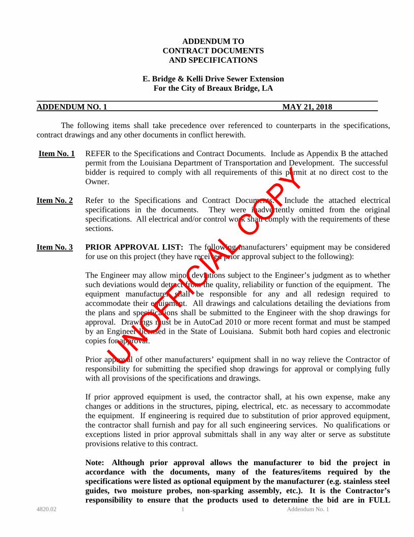
ADDENDUM TO CONTRACT DOCUMENTS
AND SPECIFICATIONS
E. Bridge & Kelli Drive Sewer Extension For the City of Breaux Bridge, LA
ADDENDUM NO. 1 MAY 21, 2018
The following items shall take precedence over referenced to counterparts in the specifications, contract drawings and any other documents in conflict herewith. Item No. 1 REFER to the Specifications and Contract Documents. Include as Appendix B the attached
permit from the Louisiana Department of Transportation and Development. The successful bidder is required to comply with all requirements of this permit at no direct cost to the Owner.
Item No. 2 Refer to the Specifications and Contract Documents. Include the attached electrical
specifications in the documents. They were inadvertently omitted from the original specifications. All electrical and/or control work shall comply with the requirements of these sections.
Item No. 3 PRIOR APPROVAL LIST: The following manufacturers’ equipment may be considered
for use on this project (they have received prior approval subject to the following):
The Engineer may allow minor deviations subject to the Engineer’s judgment as to whether such deviations would detract from the quality, reliability or function of the equipment. The equipment manufacturer shall be responsible for any and all redesign required to accommodate their equipment. All drawings and calculations detailing the deviations from the plans and specifications shall be submitted to the Engineer with the shop drawings for approval. Drawings must be in AutoCad 2010 or more recent format and must be stamped by an Engineer licensed in the State of Louisiana. Submit both hard copies and electronic copies for approval. Prior approval of other manufacturers’ equipment shall in no way relieve the Contractor of responsibility for submitting the specified shop drawings for approval or complying fully with all provisions of the specifications and drawings. If prior approved equipment is used, the contractor shall, at his own expense, make any changes or additions in the structures, piping, electrical, etc. as necessary to accommodate the equipment. If engineering is required due to substitution of prior approved equipment, the contractor shall furnish and pay for all such engineering services. No qualifications or exceptions listed in prior approval submittals shall in any way alter or serve as substitute provisions relative to this contract. Note: Although prior approval allows the manufacturer to bid the project in accordance with the documents, many of the features/items required by the specifications were listed as optional equipment by the manufacturer (e.g. stainless steel guides, two moisture probes, non-sparking assembly, etc.). It is the Contractor’s responsibility to ensure that the products used to determine the bid are in FULL
UNOFFICIA
L COPY
4820.02 2 Addendum No. 1
compliance with the specifications, including the costs for the options required to fully meet the specifications.
Section Description of Items Approved Mfr. 11300 Wet Well Coating Sherwin Williams Dura-Plate 5900, 125 mils Tnemec: 1st Coat: Tnemec Series 218-1000 Mortarclad at a minimum 1/16” -1/8” thickness to fill voids and provide a smooth finish.
2nd Coat Tnemec Series 434 Permashield 125 mils.
Item No. 4 Refer to the Specifications and Contract Documents, Section 11300 – Duplex Submersible Sewage Pump Station; Wet Well & Valve Pit. Add the following paragraph:
Surface preparation shall be in strict conformance with the coating manufacturer’s
recommendations. Upon full cure, the installed lining system shall be checked by high voltage spark detection in accordance with NACE RP0188-90 to verify a pinhole-free surface. Voltage shall be set at 11,000 volts. Areas which do not pass the spark detection test shall be corrected at no cost to the Owner and rechecked.
Item No. 5 Refer to the Contract Drawings. Section A-A on Sheet 7 is hereby revised to include the
denoted stilling tube. Item No. 6 Refer to the Specifications, Section 00820 – Special Conditions, Article 55 – Water for
Construction. Substitute the paragraph below for this Section:
All water required by the Contractor for performing the work in this Contract shall be provided for and the cost covered by the Contractor. The Contractor is advised to make arrangements with the City for all water required and for any other costs associated with obtaining such water (e.g. meter, labor to open and close fire hydrants). All costs for water, (including labor and associated costs) shall be included in the unit prices bid for the appropriate individual work items for which the water use is required.
Item No. 7 REFER to the Specifications and Contract Documents, Section 02730 – Sanitary Sewer
(Gravity). Certa-Flo PVC Gravity Sewer Pipe SDR 26 or thicker is allowable for push joint pipes. All sewer installed under roads must be jointless/fusible.
Item No. 8 REFER to the Specifications and Contract Documents, Section 00300 – Bid Form.
Substitute the attached Bid Form. This Bid Form must be utilized for the submission of all bids.
Item No. 9 REFER to the Plans for the Project and the Specifications, Section 02730 – Sanitary Sewer
(Gravity). The contractor will be allowed to install the gravity sewer pipe by boring in lieu of open cut installation if they choose to do so. The pipe may be Certainteed Certalok pipe DR 25 or thicker, or Fusible C900 PVC pipe DR 25 or thicker. The thickness of the pipe must be coordinated with the pipe manufacturer relative to pull forces; should thicker pipe be recommended by the pipe manufacturer, the thicker pipe shall be provided and the cost for the thicker pipe included in the contract unit price. The contractor shall be responsible for achieving the correct grade of the pipe, and to correct any defects in grade, etc., at no cost to
UNOFFICIA
L COPY

4820.02 3 Addendum No. 1
the Owner. The contractor shall be required to connect to each manhole with flexible connectors (e.g. Kor-N-Seal boots) as per the plans and specifications. Manholes shall conform to the contract requirements. Any couplings, materials, etc. required to install the manhole as per the details shall be included at no direct pay. Should this alternative be chosen by the contractor, the contractor shall not be paid for special backfill, embedment, surface restoration, etc., since such work will not be performed if bored. The pipe installed by this method shall be paid at the unit price for “Furnish & Install 8” Gravity Sewer” at the depth of cut indicated in the contract bid form for the appropriate depth. Payment at the unit price shall constitute full payment for all materials, labor, excavation, backfill, bore pits, mud pits, etc. The length paid shall be from center of manhole to center of manhole only (no payment for excess pipe pulled in the bore). If the contractor chooses to use this method of construction, he may use a stainless steel saddle for the service risers, as depicted in the detail included in this addendum. There shall be no additional pay for this item; it shall be paid as a service riser, and payment shall include all materials including but not limited to limestone encasement, clamps, etc. Limestone will not be measured for separate payment; it shall be included in the unit price for the service riser. The hole for the service shall be cut with a hole saw and shall be smooth, round, and without defects of any kind.
Item No. 10 As a point of emphasis, where jack or bores are shown on the plan, the contractor shall only
be paid for the length of bore shown on the plans. The contractor shall not be paid for additional bore length in excess of bore lengths shown on the plans.
Received by: Signed: Dated: Company:
FAX THIS SIGNED PAGE TO DOMINGUE, SZABO & ASSOCIATES, INC. AT
337-237-7132; OR RESPOND TO EMAIL ACKNOWLEDGING RECEIPT OF ADDENDUM
End of Addendum No. 1
ABCD
UNOFFICIA
L COPY
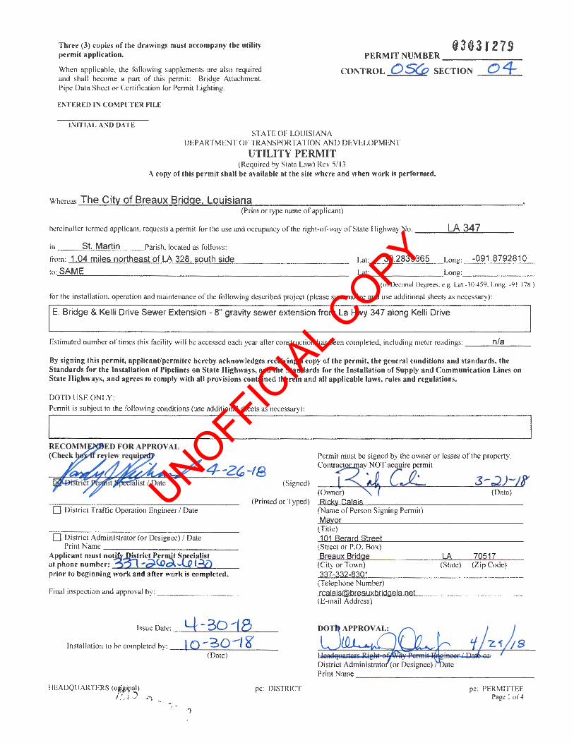
0363f27!l Three (3) copies of the drawings must accompany the utility permit application. PERMIT NUMBER------.,--
CONTROL C) S(o SECTION 0 4 When applicable, the following supplements are also required and shall become a part of this permit: Bridge Attachment. Pipe Data Sheet or Certitication for Permit Lighting.
ENTERED IN COMPUTER FILE
INITIAL A D DATE STATE OF LOUISIAN A
DEPARTMENT OF TRANSPORTATION AND DEVELOPMENT
UTILITY PERMIT (Required by State Law) Rev 5/ 13
A copy of this permit shall be available at the site where and when work is performed.
Whereas The City of Breaux Bridge, Louisiana (Print or type name of applicant)
hereinafter termed applicant, requests a permit for the use and occupancy of the right-of-way of State Highway No. -----=L:!.A..:...::3:<...4 ..... 7.:..-__ _
in St. Martin Parish, located as follows:
!Tom: 1.04 miles northeast of LA 328 south side
to: SAME
Lat:. _ _;:3....::.0=.2=8.::...39::....:3:..:::6....::.5_Long: -091 .8792810
Lat: Long: ______ _
(in Decimal Degrees, e.g. Lat:-30.459, Long: -9 1.178)
for the installation, operation and maintenance of the following described project (please summarize and use additional sheets as necessary):
E . Bridge & Kelli Drive Sewer Extension- 8" gravity sewer extension from La Hwy 347 along Kelli Drive
Estimated number of times this faci lity will be accessed each year after construction has been completed, including meter readings: n/a
By signing this permit, applicantlpermitee hereby acknowledges receiving a copy oftbe permit, the general conditions and standards, the Standards for the Installation of Pipelines on State Highways, and the Standards for the Installation of Supply and Communication Lines on State Highways, and agrees to comply with all provisions contained therein and all applicable laws, rules and regulations.
DOTD USE ONLY: Permit is subject to the following conditions (use addi tional sheets as necessary):
4-2~-18 (Signed)
(Owner) (Date)
0 District Traffic Operation Engineer I Date (Printed or Typed) ~R~i.s...ck~y~C~a~la;I.Lis.._-=-:--:---=:--:-:----------
(Name of Person Signing Pern1it)
0 District Administrator (or Designee) I Date Print Name -------------
Applicant must notif¥.JE:.trict PJ rmtt SpeEialist at phone number:~ -;;).\.Dc:A ... I...J2 I ?f) prior to beginning work and after work is completed.
Final inspection and approval by: ________ _
Issue Date: _4__..__-_,3:::....0=--_,1.....,8~-lnstallation to be completed by: - --'-1 "'0£_-_3-=-0-=-_-_I_g.::._ __
(Date)
HEADQUARTERS (o "';4;al)
!? 21 zar. pc: DISTRICT
Mayor (Title) 101 Berard Street
(Street or P.O. Box) Breaux Bridge
(City or Town) 337-332-8301
(Telephone Number) rcalais@breauxbridgela net (E-mail Address)
LA 70517 (State) (Z ip Code)
pc: PERMITIEE Page I of 4
UNOFFICIA
L COPY

Permit Number03D ~} d:l. t:)' The following general conditions and standards shall apply:
FIRST: That, the rights and privileges granted herein shall be nonexclusive and shall not be construed to be any broader than those expressly set out in Acts of the Legislature of the State of Louisiana, regardless of the language used in this perm it and that any facilities placed on the highway right-of-way shall be placed in accordance with existing laws and the standards of the Department. SECOND: That, all facilities thereto, after having been erected, shall at all times be subject to inspection and the right is reserved to require such changes, additions, repairs, relocations and removal as may at anytime be considered necessary to pe1mit the relocation, reconstruction, widening and maintaining of the highway and to provide proper and safe protection to life and property on or adjacent to the highway, or in the interest of safety to traffic on the highway and that the cost of making such changes, additions, repairs and relocations shall be borne by the applicant, and that all of the cost of the work to be accomplished under this permit shall be borne by the permittee who agrees to hold the Department harmless therefore. TH IRD: That, the proposed facilities or their operation or their maintenance shall not unreasonably interfere with the facilities or the operation or maintenance of the facilities of other persons, firms or corporations previously issued permits of use and occupancy, and the proposed facilities shall not be dangerous to persons or property using or occupying the highway or using facilities constructed under previously granted permits of use and occupancy; and that the Department's records of prior permits are available, it being the duty of the applicant to determine the existence and location of all facilities within the highway right of way. FOURTH: That, installations within the highway right-of-way shall be in accordance with applicable provisions contained in the following: AASHTO Guide for Accommodating Utilities within Highway Right of Way, Code of Federal Regulations 23 (CFR 23), National Electrical Safety Code C2, 1996 Federal Telecommunications Act. Those facilities not included in the above mentioned documents shall be in accordance with accepted practice. Where standards of the Department exceed those of the above cited codes, the standards of the Department shall apply. The Department reserves the right to modifY its policies as may be required if conditions warrant. FIFTH : That, data relative to the proposed location, relocation and design of fixtures or appurtenances as may be required by the Department shall be furnished to the Department by the applicant free of cost, and that the applicant shall make any and all changes or additions necessary to make the proposed facilities thereto satisfactory to the Department. SIXTH: That, cutting and trimming of trees, shrubs, etc ., shall be in accordance with the Department's EDSM IV 2.1.6 and Vegetation Manual , as revised. SEVENTH: That, the applicant agrees to defend, indemnifY, and hold harmless the Department and its duly appointed agents and employees from and against any and all claims, suits, liabilities, losses, damages, costs or expenses, including attorneys' fees sustained by reason of the exercise of this permit, whether or not the same may have been caused by the negligence of the Department, its agents or employees, provided, however, that the provisions of this last clause( whether or not the same may have been caused by the negligence of the Department, its agents or employees) shall not apply to any personal injury or property damage caused by the sole negligence of the Department, its agents or employees, unless such sole negligence shall consist or shall have consisted entirely and only of negligence in the granting of a permit or permits. EIGHTH: That, the applicant is the owner of the facility for which a permit is requested, and is responsible for maintenance of such: and any permit granted by the Department is granted only insofar as the Department had the power and right to grant the same. NINTH : That, any permit granted by the Department is subject to revocation at any time. TENTH: That, signing for warning and protection of traffic in instances where workmen, equipment or materials are in close proximity to the roadway surfacing, shall be in accordance with requirements contained in the Department's Manual on Uniform Traffic Control Devices. No vehicles, equipment and/or materials shall operate from, or be parked , stored or stock piled on any highway, median, or in an area extending from the outer edge of the shoulder of the highway on one side to the outer edge of the shoulder of the highway on the opposite side or in the median of any divided highway. ELEVENTH: That, all provisions and standards contained herein relative to the installation of utilities shall apply to future operation, service and maintenance of utilities. TWELFTH : That, drainage in highway side and cross ditches must be maintained at all times. The entire highway right of way affected by work under a permit must be restored to as good a condition as existed prior to beginning work to the complete satisfaction of the Department's R/W Permit Engineer. THIRTEENTH: Any non-metallic or non-conductive underground facility must be installed with a non-corrosive metallic wire or tape placed directly over and on the center of the facility for its entire length within highway right-of-way. Wire or tape must be connected to all facilities. FOURTEENTH: Prior to performing any excavations, the applicant is required to call Louisiana One Call. If installing any underground facilities such as cable or conduits, the applicant must be a member of Louisiana One Call. In addition, the applicant must contact DOTD at 1-800-259-4929 or DOTD-FiberLocates(@. la.gov at least 24 hours prior to performing any excavation on DOTD Right-of-way (either for installation or maintenance).
HEADQUARTERS (original) pc: DISTRJ CT pc: PERMITTEE Page 2 of 4
UNOFFICIA
L COPY

Pennit Number 030~ )9-J. q STANDARDS FOR THE INSTALLATION OF PIPELINES ON STATE HIGHWAYS
A. GENERAL (I) All materials and workmanship shall conform to the requirements of the applicable industry code and to Department
specifications. (2) All safety precautions for the protection of the traveling public must be observed. Undue delay to traffic will not be
tolerated . (3) All excavations within the limits of the right-of-way shall be backfilled and tamped in six inch layers to the density of
the adjacent undisturbed soil. Where sod is removed or destroyed, it shall be replaced. Where it is necessary to make excavations in the shoulder, the top six inches of backfill shall be sand-clay gravel or equivalent. Where existing spoil material is, at the discretion of the Department, unsuitable for backfLII, select material shall be furnished in lieu thereof and the existing material disposed of by approved methods.
(4) Protruding valves and other above ground appurtenances shall not be installed at any point within the right of way of the highway except for vents, markers, etc., which may be installed at the right-of-way line, unless specifically approved herein.
B. PARALLEL TO THE HIGHWAY (All provisions of general standards to apply.) (1) Pipelines paralleling the highway:
(a) shall occupy the last few feet of the right-of-way back of the ditch except where upon showing of actual necessity a permit is issued for another location;
(b) shall have a minimum earth cover of twenty-four (24) inches; (c) shall have a minimum clearance of twenty-four (24) inches below existing or proposed drainage structures, where
possible. (2) Utilities paralleling the highway are limited to distribution facilities.
C. CROSSING THE HIGHWAY (All provisions of general standards apply.) (1) Uncased pipelines may be permitted, provided the conditions outlined in E.D.SM. IV 2.1.9 are met. (2) If the permittee elects to use casing, it must extend from right-of-way to right-of-way, and be properly vented and
marked at or beyond the right-of-way line. (3) For cased pipelines, the casing shall have at least four (4) feet of cover below the roadway and two (2) feet of cover
below ditches or drainage structures. Uncased pipelines shall have at least five (5) feet and three (3) feet of cover respectively.
{4) Crossings shall be made at as nearly right angles to the highway as possible. No existing drainage structure under the highway may be used for this purpose.
(5) Construction methods used shall be in accordance with the following requirements: (a) Cutting the surface or tunneling under it is specifically prohibited. (b) Installation shall be made either by boring or jacking under and through the highway at least from ditch bottom to
ditch bottom. In the absence of ditches, or along sections of highway with curb or gutter, boring or jacking shall extend beyond the outside edge of the traveled way to a point at least equal to three (3) times the vertical difference between the elevation of the roadway surfacing and the elevation of the top of the cable. Where width of right-of-way is insufficient to enable compliance with this requirement or where it is necessary to make a connection to an existing parallel facility which precludes compliance, the distance shall be to the right-of-way line or to the parallel facility. Any voids or overbreaks resulting from this shall be backfilled with grout consisting of a cement mortar or slurry of fine sand or clay, as conditions require. Excavating an open ditch to the edge of the pavement and boring and jacking the remainder ofthe distance is prohibited. Jacking and boring shall be done in accordance with Section 728 of the La. Standard Specifications for Roads and Bridges, latest edition.
D. REMOVAL AND ABONDONMENT OF UTILITY FACILITIES (1) All facilities installed within state highway right-of-way shall be removed and disposed of by their owner as soon as
they stop serving a useful purpose. Facilities may be abandoned under the following circumstances. (a) Pipelines and casings crossing highways or other hard surfaces may be abandoned in place, with the
recommendation of the district utility and permit specialist and the project engineer, and with the approval of the headquarters utility and permit engineer.
(b) Pipelines and casings installed along highways, may be abandoned in place, with the recommendation of the district utility and permit specialist and the project engineer, and with the approval of the headquarters utility and permit engineer, provided that they are less than 6 inches in diameter, or that they are buried with more than 8 feet or cover.
(c) Electrical and communication facilities installed within a casing, and crossing under highways or other hard surfaces may be abandoned in place with the recommendation of the district utility and permit specialist and the project engineer, and with the approval of the headquarters utility and permit engineer, provided that the cable is removed from the casing.
(d) Uncased cables crossing under highways or other hard surfaces may be abandoned in place provided that they are removed to a point as near to the edge of the highway as feasible.
HEADQUAR1ERS (original) pc: DISTRICT pc: PERMITIEE Page 3 of4
UNOFFICIA
L COPY

Permit Number {JjOS I d:-.... f1 (e) Electrical and communication cables installed along highways may be abandoned in place, with the
recommendation of the district utility and penn it specialist and the project engineer, and with the approval of the headquarters utility and pennit engineer, provided that they are less than 4 inches in diameter, or that they are buried with more than 8 feet of cover.
(f) All above ground facilities installed along state highways shall be removed and disposed of by their owner as soon as they stop serving a useful purpose.
(g) Facilities that are located so that their removal would be likely to result in damage to the highway, or to other facilities, may be abandoned in place, with the recommendation of the district utility and permit specialist and the project engineer, and with the approval of the headquarters utility and permit engineer. The procedure for abandoning these facilities will be specified on a case-by-case basis; however, in general, sections shall be removed here possible, and all remaining lines shall be filled with grout.
(2) Where it is not possible nor feasible to remove pipelines and/or casings under existing highways, such pipelines and/or casings may be abandoned in place provided removals shall be accomplished by the owner, as near to the highway on each side as possible and in all cases, beyond existing ditches to right-of-way lines, and further provided that all pipelines and/or casings abandoned under the highway shall be abandoned in accordance with D.O.T. Title 49 (i.e., pipelines are purged, capped, and filled with grout; note that when highway construction will remove the line in the near future, the DOTD's project engineer may approve the use of water in place of grout).
(3) Pipelines and cables shall be removed from abandoned casings where possible. (4) In all cases the highway right-of-way shall be repaired, at the permittee' s expense, to match DOTD standards. An
approved backfill material shall be used to fill in any trenches or low areas, and shall be compacted to the same density as the surrounding soil. Any desirable trees or shrubs that are damaged shall be replaced, and any other damages (i.e. to subsurface drainage, traffic signs, etc.) shall be repaired.
(5) Companies who fail to comply with this by leaving their facilities within highway right-of-way after they are no longer used, or by not repairing the right-of-way after removing their facilities, shall not receive any pennits until the situation is rectified.
(6) In cases where the DOTD decides that it is necessary to remove a facility and/or to repair highway right-of-way damaged by a utility or the utility's facility, the company shall be invoiced for costs to the DOTD for removing abandoned facilities, or for repairing damaged right-of-way. Unpaid invoices shall be referred to DOTD's accounting section for further action.
(7) Note that a recommendation for abandonment by the project engineer is required only on construction projects. The district construction engineer should be consulted by the district utility and pennit specialist when an abandonment may cause a potential problem with future construction. The assistant district administrator should be consulted by the district utility and pennit specialist when an abandonment may cause a potential maintenance problem.
(8) The owner of the abandoned facilities shall maintain full responsibility for any future problems caused by the facilities, and shall remove the facilities upon receiving a written request from the DOTD. The cost of removing these facilities shall be borne by the owner and the DOTD shall assume no liability for this cost.
STANDARDS FOR THE INSTALLATION OF SUPPLY AND COMMUNICATION LINES ON STATE IDGHWAYS
A. All pole lines shall occupy the last few feet of the right-of-way behind the ditch but shall be no further from the right-ofway line than one-half of the width of the cross-anns plus one foot, except where upon a showing of actual necessity a permit is issued for another location.
B. A minimum vertical clearance of twenty (20) feet shall be maintained between the traveled surface of the highway and any aerial installation. In no case shall the vertical clearance for an overhead utility line be less than the clearance required by the National Electrical Safety Code. A minimum clearance of sixteen (16) feet shall be maintained between existing ground elevation and any aerial installation when such installation is within highway right-of-way but does not cross the traveled surface of a highway.
C. Where supply and/or communication lines are placed underground, the standards for pipelines shall govern. Underground electric facilities must have at least four (4) feet of cover and must be encased when crossing a highway. These facilities must also be adequately marked by appropriate signs at specified locations.
HEADQUARTERS (original) pc: DIS1RICT pc: PERMITI'EE Page 4 of4
UNOFFICIA
L COPY
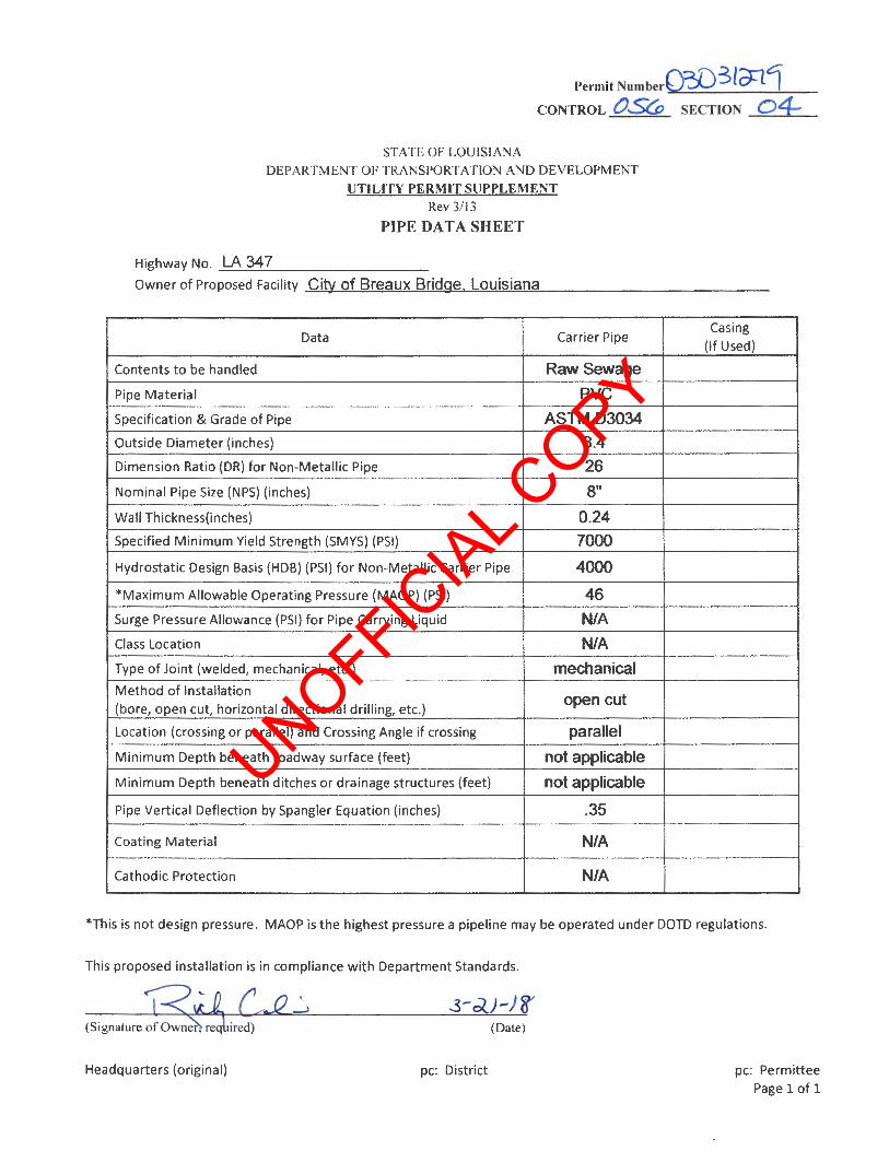
Permit Number0;:[)3ld=11 CONTROL 0..5Co SECTION 04
STATE OF LOUISIANA
DEPARTMENT OF TRANSPORTATION AND DEVELOPMENT
UTILITY PERMlT SUPPLEMENT Rev 3/13
PIPE DATA SHEET
Highway No. -=L::...A.:....;3:::...4.:..:7~-------0wner of Proposed Facility City of Breaux Bridge. Louisiana
Data Carrier Pipe
Contents to be handled Raw Sewage
Pipe Material PVC
Specification & Grade of Pipe ASTM 03034
Outside Diameter (inches) 8.4
Dimension Ratio (DR) for Non-Metallic Pipe 26
Nominal Pipe Size (NPS) (inches) 8"
Wall Thickness(inches) 0.24
Specified Minimum Yield Strength (SMYS) (PSI) 7000
Hydrostatic Design Basis (HDB) (PSI) for Non-Metallic Carrier Pipe 4000
*Maximum Allowable Operating Pressure (MAOP) (PSI) 46
Surge Pressure Allowance (PSI) for Pipe Carrying Liquid N/A
Class Location N/A
Type of Joint {welded, mechanical, etc.) mechanical Method of Installation
open cut (bore, open cut, horizontal directional drilling, etc.)
Location {crossing or parallel) and Crossing Angle if crossing parallel
Minimum Depth beneath roadway surface (feet) not applicable
Minimum Depth beneath ditches or drainage structures (feet) not applicable
Pipe Vertical Deflection by Spangler Equation (inches) .35
Coating Material N/A
Cathodic Protection N/A
Casing (If Used)
*This is not design pressure. MAOP is the highest pressure a pipeline may be operated under DOTD regulations.
This proposed installation is in compliance with Department Standards.
(Date)
Headquarters (original) pc: District pc: Permittee Page 1 of 1
UNOFFICIA
L COPY
~ O?;l) 3 ro.-'lOj ~ ------------------------------------------------------------~--------------------------------------------------r---------------------~~~~~~--~--------------------~
"' 3: -o ...;
·~ ., 0..
0
b 0
I{) 0 ci N <XJ -.t ./ I{) 0 ci N <XJ -.t ./ 0 0 ci N <XJ -.t ./ Vi
I J
h 0
00 00 L[)
0... 0 1-
Vi "<t N L[)
20
16
12
8 0+
EXISTING ATMOS 2"
r STEEL GAS PIPELINE ( 2212)
CONSTRUCT NEW MANHOLE, CUT AND CONNECT EXISTING PIPES WITH FLEXIBLE
+I ...-
..-tO
...- ...-~ ..
a.. Io :::!:1-
3.35'
v,.......
v I
v
"' ~'-- t--I{)
..-I{)
00 ..-IX) ~
I"> :::!:z
WATERTIGHT CONNECTORS. SEEffi
KELLI DR. (50' R/W}
MH#11 TOP 16.1± INV 8.55
f.L.Atf 1 "=40'
LA HWY 347
18.88
PROPOSED a•x262' PVC GRAVITY SANITARY SEWER MAIN 0 0.4X
20
16
RIGHT OF WAY
B'"x262' 0 0.4" I I I I I I I I
EXISTING 8" PVC SEWER LINE
I I I I I I I I
PROFILE 1 "=40' HORIZONTAL
" ' = 4 VERTICAL
1+00 1+
12
8 50
1000
VICINITY MAP
2000 0---1-000 ---Scale in Feet
EXISTING SEWER TO REMAIN
FULL CIRCLE SOLID S.S. COUPLING
PROPOSED 8" PVC SEWER PIPE
FULL CIRCLE SOLID S.S. COUPLING
EXISTING 8" PVC SEWER MAIN
SECTION A-A
' A
PRE-CAST CONCRETE MANHOLE WITH INTEGRAL BASE
NEW 8" PVC SEWER MAIN
12"
,p~~~~lm~ ,~=;='!~~
REQ'D COMPACTED LIMESTONE TO TOP OF PIPE
COMPACTED LIMESTONE BASE LIMITS OF MANHOLE EXCAVATION
CONNECTION TO EXISTING SEWER MAIN
N.T.S.
/
/ " I 1
I MIN.
I \
Cl RING
CAST IRON RING AND COVER
GROUT COLLAR DOWN TO CONE
REINFORCED CONCRETE DONUT FOR HEIGHT ADJUSTMENT
CONCRETE CONE (CONCENTRIC OR ECCENTRIC)
LIFT HOLES TO BE PLUGGED FLUSH & UNIFORM INSIDE & OUTSIDE WITH PRECO PATCH (O.A.E.).
ALL EXTERIOR JOINTS (SECTIONS, COLLARS, MANHOLE RINGS, ETC.) SHALL BE SEALED FLUSH & UNIFORM WITH GROUT AFTER VACUUM TEST.
ALL INTERIOR JOINTS (SECTIONS, COLLARS, MANHOLE RINGS, ETC.) SHALL BE SEALED FLUSH & UNIFORM WITH PRECO PATCH (O.A.E.) AFTER VACUUM TEST.
4• -0" 6" MIN.
5" TH ICK (TYP.) 5" TH ICK (TYP.)
TYPICAL SEWER MANHOLE
SHALLOW &: TYPICAL SEWER MANHOLE. PRE-CAST CONCRETE 1. ALL SECTIONS ARE CUSTOM MADE AND CONFORM TO ASTM SPECIFICATIONS
DESIGNATION C-478 OR LATEST REVISION FOR PRECAST CONCRETE MANHOLE, RISERS, AND TOPS.
2. MAINS AND SERVICES SHALL EXTEND 6" INTO MANHOLES. 3. INVERT SHALL HAVE A MIN. 15" SLOPE, HEIGHT TO 1/2 PIPE, AND LONG RADIUS
TURNS. 4. OPENINGS FOR SEWER PIPE CAN 1;3E MADE AT ANY LOCATION BELOW CONCRETE
DONUT'S. 5. WATERTIGHT CONNECTIONS SHALL BE INSTALLED ON ALL MANHOLE PENETRATIONS. 6. ALL PIPE PENETRATIONS REQUIRE PRECO PATCH (O.A.E.) INSIDE AND/OR OUTSIDE. 7. ALL JOINTS SHALL BE 0-RING JOINTS, SEALED AS DESCRIBED ABOVE. B. MANHOLES OUTSIDE OF THE PAVED RIGHT - OF -WAY OR OTHER PAVED SURFACES
SHALL HAVE A STAINLESS STEEL "RAINSTOPPER" MANHOLE COVER INSERT.
SEWER MANHOLE - PRE-CAST CONCRETE
N.T.S . 1-005
DOTD PERMIT DRAWING LA HWY 347
SEWER CONNECTION
. EAST BRIDGE STREET & KEW DRIVE EXTENSION
FOR THE CITY OF BREAUX BRIDGE, LA
Prepared by
a. ASSOCIATES, INCORPORATED """" .... leW IIQI5
lafayette, lauialana
Fll£ NO. 4820.05-P-2
UNOFFICIA
L COPY
CONSTRUCTION DOCUMENTS
(Table of Contents)
TOC - 1
PROJECT NAME: Breaux Bridge
ARCHITECT: Domingue Szabo & Associates
PROJECT NO: 18030
TABLE OF CONTENTS
DIVISION 16 - ELECTRICAL
Electrical Sections: 16050 Basic Electrical Materials and Methods 16060 Grounding and Bonding 16120 Conductors and Cables 16130 Raceways and Boxes 16410 Enclosed Switches and Circuit Breakers 16700 Duplex Control Panel 16800 Lift Station Scada Panel
END OF TABLE OF CONTENTS
UNOFFICIA
L COPY
BASIC ELECTRICAL MATERIALS AND METHODS 16050 - 1
Section 16050 – Basic Electrical Materials and Methods
`PART 1 - GENERAL
1.1 SUMMARY
A. This Section includes the following:
1. Supporting devices for electrical components.
2. Electricity-metering components.
3. Concrete equipment bases.
4. Touchup painting.
1.2 DEFINITIONS
A. EMT: Electrical metallic tubing.
B. FMC: Flexible metal conduit.
C. IMC: Intermediate metal conduit.
D. LFMC: Liquidtight flexible metal conduit.
E. RNC: Rigid nonmetallic conduit.
1.3 QUALITY ASSURANCE
A. Electrical Components, Devices, and Accessories: Listed and labeled as defined in NFPA 70,
Article 100, by a testing agency acceptable to authorities having jurisdiction, and marked for intended use.
B. Comply with NFPA 70.
1.4 COORDINATION
A. Coordinate chases, slots, inserts, sleeves, and openings with general construction work and arrange in
building structure during progress of construction to facilitate the electrical installations that follow.
1. Set inserts and sleeves in poured-in-place concrete, masonry work, and other structural
components as they are constructed.
B. Sequence, coordinate, and integrate installing electrical materials and equipment for efficient flow of the
Work.
C. Where electrical identification devices are applied to field-finished surfaces, coordinate installation of
identification devices with completion of finished surface.
UNOFFICIA
L COPY

BASIC ELECTRICAL MATERIALS AND METHODS 16050 - 2
D. Coordinate connecting to all equipment with equipment provider. Contractor to refer to equipment
installation documents prior to any rough-in.
E. The contractor shall label the main service disconnecting means with the maximum available fault current
shall be listed on the device to meet the requirements of NFPA 70:110.24. The labeling shall be
engraved plastic. The maximum available fault current shall be obtained from the electrical utility for the
secondary side of the utility transformer.
PART 2 - PRODUCTS
2.1 SUPPORTING DEVICES
A. Material: Cold-formed steel, with corrosion-resistant coating acceptable to authorities having jurisdiction.
B. Metal Items for Use Outdoors or in Damp Locations: Hot-dip galvanized steel.
C. Slotted-Steel Channel Supports: Flange edges turned toward web, and 9/16-inch- (14-mm-) diameter
slotted holes at a maximum of 2 inches (50 mm) o.c., in webs.
D. Raceway and Cable Supports: Manufactured clevis hangers, riser clamps, straps, threaded C-clamps with
retainers, ceiling trapeze hangers, wall brackets, and spring-steel clamps or click-type hangers.
E. Cable Supports for Vertical Conduit: Factory-fabricated assembly consisting of threaded body and
insulating wedging plug for nonarmored electrical cables in riser conduits. Plugs have number and size of
conductor gripping holes as required to suit individual risers. Body constructed of malleable-iron casting
with hot-dip galvanized finish.
F. Expansion Anchors: Carbon-steel wedge or sleeve type.
G. Toggle Bolts: All-steel springhead type.
H. Powder-Driven Threaded Studs: Heat-treated steel.
2.2 EQUIPMENT FOR ELECTRICITY METERING BY CONTRACTOR
A. Meter: Contractor shall provide metering per the local utility. Contractor shall provide all necessary
enclosures, meter cans, etc. per the local utility requirements.
2.3 CONCRETE BASES
A. Concrete: 3000-psi (20.7-MPa), 28-day compressive strength as specified in Division 3
2.4 TOUCH-UP PAINT
A. For Equipment: Equipment manufacturer's paint selected to match installed equipment finish.
B. Galvanized Surfaces: Zinc-rich paint recommended by item manufacturer.
UNOFFICIA
L COPY

BASIC ELECTRICAL MATERIALS AND METHODS 16050 - 3
PART 3 - EXECUTION
3.1 ELECTRICAL EQUIPMENT INSTALLATION
A. Headroom Maintenance: If mounting heights or other location criteria are not indicated, arrange and
install components and equipment to provide the maximum possible headroom.
B. Materials and Components: Install level, plumb, and parallel and perpendicular to other building systems
and components, unless otherwise indicated.
C. Equipment: Install to facilitate service, maintenance, and repair or replacement of components. Connect
for ease of disconnecting, with minimum interference with other installations.
D. Right of Way: Give to raceways and piping systems installed at a required slope.
3.2 ELECTRICAL SUPPORTING DEVICE APPLICATION
A. Damp Locations and Outdoors: Hot-dip galvanized materials or nonmetallic, U-channel system
components.
B. Dry Locations: Steel materials.
C. Support Clamps for PVC Raceways: Click-type clamp system.
D. Selection of Supports: Comply with manufacturer's written instructions.
E. Strength of Supports: Adequate to carry present and future loads, times a safety factor of at least four;
minimum of 200-lb (90-kg) design load.
3.3 SUPPORT INSTALLATION
A. Install support devices to securely and permanently fasten and support electrical components.
B. Install individual and multiple raceway hangers and riser clamps to support raceways. Provide U-bolts,
clamps, attachments, and other hardware necessary for hanger assemblies and for securing hanger rods
and conduits.
C. Support parallel runs of horizontal raceways together on trapeze- or bracket-type hangers.
D. Size supports for multiple raceway installations so capacity can be increased by a 25 percent minimum in
the future.
E. Support individual horizontal raceways with separate, malleable-iron pipe hangers or clamps.
F. Install 1/4-inch- (6-mm-) diameter or larger threaded steel hanger rods, unless otherwise indicated.
3.4 CONCRETE BASES
A. Provide a concrete base for all floor mounted equipment. Construct concrete bases of dimensions
indicated, but not less than 4 inches (100 mm) larger, in both directions, than supported unit. Follow
UNOFFICIA
L COPY

BASIC ELECTRICAL MATERIALS AND METHODS 16050 - 4
supported equipment manufacturer's anchorage recommendations and setting templates for anchor-bolt
and tie locations, unless otherwise indicated. Use 3000-psi (20.7-MPa), 28-day compressive-strength
concrete and reinforcement as specified in Division 3 Section "Cast-in-Place Concrete."
3.5 REFINISHING AND TOUCH-UP PAINTING
A. Refinish and touch up paint.
1. Clean damaged and disturbed areas and apply primer, intermediate, and finish coats to suit the
degree of damage at each location.
2. Follow paint manufacturer's written instructions for surface preparation and for timing and
application of successive coats.
3. Repair damage to galvanized finishes with zinc-rich paint recommended by manufacturer.
4. Repair damage to PVC or paint finishes with matching touchup coating recommended by
manufacturer.
3.6 CLEANING AND PROTECTION
A. On completion of installation, including outlets, fittings, and devices, inspect exposed finish. Remove
burrs, dirt, paint spots, and construction debris.
B. Protect equipment and installations and maintain conditions to ensure that coatings, finishes, and cabinets
are without damage or deterioration at time of Substantial Completion.
END OF SECTION 16050
UNOFFICIA
L COPY
GROUNDING AND BONDING 16060 - 1
Section 16060 – Grounding and Bonding
PART 1 - GENERAL
1.1 RELATED DOCUMENTS
A. Drawings and general provisions of the Contract, including General and Supplementary Conditions and
Division 1 Specification Sections, apply to this Section.
1.2 SUMMARY
A. This Section includes methods and materials for grounding systems and equipment.
1. Underground grounding.
1.3 QUALITY ASSURANCE
A. Electrical Components, Devices, and Accessories: Listed and labeled as defined in NFPA 70,
Article 100, by a testing agency acceptable to authorities having jurisdiction, and marked for intended
use.
B. Comply with UL 467 for grounding and bonding materials and equipment.
PART 2 - PRODUCTS
2.1 CONDUCTORS
A. Insulated Conductors: Copper or tinned-copper wire or cable insulated for 600 V unless otherwise
required by applicable Code or authorities having jurisdiction.
B. Bare Copper Conductors:
1. Solid Conductors: ASTM B 3.
2. Stranded Conductors: ASTM B 8.
3. Tinned Conductors: ASTM B 33.
4. Bonding Cable: 28 kcmil, 14 strands of No. 17 AWG conductor, 1/4 inch (6 mm) in diameter.
5. Bonding Conductor: No. 4 or No. 6 AWG, stranded conductor.
6. Bonding Jumper: Copper tape, braided conductors, terminated with copper ferrules; 1-5/8 inches
(41 mm) wide and 1/16 inch (1.6 mm) thick.
7. Tinned Bonding Jumper: Tinned-copper tape, braided conductors, terminated with copper
ferrules; 1-5/8 inches (41 mm) wide and 1/16 inch (1.6 mm) thick.
C. Bare Grounding Conductor and Conductor Protector for Wood Poles:
1. No. 4 AWG minimum, soft-drawn copper.
2. Conductor Protector: Half-round PVC or wood molding. If wood, use pressure-treated fir or
cypress or cedar.
UNOFFICIA
L COPY

GROUNDING AND BONDING 16060 - 2
D. Grounding Bus: Rectangular bars of annealed copper, 1/4 by 2 inches by 24” minimum in cross section,
unless otherwise indicated; with insulators.
2.2 CONNECTORS
A. Listed and labeled by a nationally recognized testing laboratory acceptable to authorities having
jurisdiction for applications in which used, and for specific types, sizes, and combinations of conductors
and other items connected.
B. Bolted Connectors for Conductors and Pipes: Copper or copper alloy, bolted pressure-type, with at least
two bolts.
1. Pipe Connectors: Clamp type, sized for pipe.
C. Welded Connectors: Exothermic-welding kits of types recommended by kit manufacturer for materials
being joined and installation conditions.
2.3 GROUNDING ELECTRODES
A. Ground Rods: Copper-clad steel, sectional type; 3/4 inch by10 feet (19 mm by 3 m) in diameter.
PART 3 - EXECUTION
3.1 APPLICATIONS
A. Conductors: Install solid conductor for No. 8 AWG and smaller, and stranded conductors for
No. 6 AWG and larger, unless otherwise indicated.
B. Underground Grounding Conductors: Install bare tinned-copper conductor, No. 2/0 AWG minimum.
1. Bury at least 24 inches below grade.
2. Duct-Bank Grounding Conductor: Bury 12 inches above duct bank when indicated as part of
duct-bank installation.
C. Isolated Grounding Conductors: Green-colored insulation with continuous yellow stripe. On feeders
with isolated ground, identify grounding conductor where visible to normal inspection, with alternating
bands of green and yellow tape, with at least three bands of green and two bands of yellow.
D. Grounding Bus: Install in electrical and telephone equipment rooms, in rooms housing service
equipment, and elsewhere as indicated.
1. Install bus on insulated spacers 1 inch , minimum, from wall 6 inches above finished floor, unless
otherwise indicated.
2. Where indicated on both sides of doorways, route bus up to top of door frame, across top of
doorway, down to specified height above floor, and connect to horizontal bus.
E. Conductor Terminations and Connections:
1. Pipe and Equipment Grounding Conductor Terminations: Bolted connectors.
2. Underground Connections: Welded connectors, except at test wells and as otherwise indicated.
UNOFFICIA
L COPY

GROUNDING AND BONDING 16060 - 3
3. Connections to Ground Rods at Test Wells: Bolted connectors.
4. Connections to Structural Steel: Welded connectors.
3.2 EQUIPMENT GROUNDING
A. Install insulated equipment grounding conductors with all feeders and branch circuits.
B. Install insulated equipment grounding conductors with the following items, in addition to those required
by NFPA 70:
1. Feeders and branch circuits.
2. Lighting circuits.
3. Receptacle circuits.
4. Single-phase motor and appliance branch circuits.
5. Three-phase motor and appliance branch circuits.
6. Flexible raceway runs.
C. Signal and Communication Equipment: For telephone, alarm, voice and data, and other communication
equipment, provide No. 4 AWG minimum insulated grounding conductor in raceway from grounding
electrode system to each service location, terminal cabinet, wiring closet, and central equipment location.
1. Service and Central Equipment Locations and Wiring Closets: Terminate grounding conductor on
a 1/4-by-2-by-12-inch grounding bus.
2. Terminal Cabinets: Terminate grounding conductor on cabinet grounding terminal.
D. Metal Poles Supporting Outdoor Lighting Fixtures: Install grounding electrode and a separate insulated
equipment grounding conductor in addition to grounding conductor installed with branch-circuit
conductors.
3.3 INSTALLATION
A. Grounding Conductors: Route along shortest and straightest paths possible, unless otherwise indicated or
required by Code. Avoid obstructing access or placing conductors where they may be subjected to strain,
impact, or damage.
B. Common Ground Bonding with Lightning Protection System: Comply with NFPA 780 and UL 96 when
interconnecting with lightning protection system. Bond electrical power system ground directly to
lightning protection system grounding conductor at closest point to electrical service grounding electrode.
Use bonding conductor sized same as system grounding electrode conductor, and install in conduit.
C. Ground Rods: Drive rods until tops are 2 inches (50 mm) below finished floor or final grade, unless
otherwise indicated.
1. Interconnect ground rods with grounding electrode conductor below grade and as otherwise
indicated. Make connections without exposing steel or damaging coating, if any.
2. For grounding electrode system, install at least three rods spaced at least one-rod length from each
other and located at least the same distance from other grounding electrodes, and connect to the
service grounding electrode conductor.
D. Bonding Straps and Jumpers: Install in locations accessible for inspection and maintenance, except
where routed through short lengths of conduit.
UNOFFICIA
L COPY

GROUNDING AND BONDING 16060 - 4
1. Bonding to Structure: Bond straps directly to basic structure, taking care not to penetrate any
adjacent parts.
2. Bonding to Equipment Mounted on Vibration Isolation Hangers and Supports: Install so vibration
is not transmitted to rigidly mounted equipment.
3. Use exothermic-welded connectors for outdoor locations, but if a disconnect-type connection is
required, use a bolted clamp.
E. Grounding and Bonding for Piping:
1. Metal Water Service Pipe: Install insulated copper grounding conductors, in conduit, from
building's main service equipment, or grounding bus, to main metal water service entrances to
building. Connect grounding conductors to main metal water service pipes, using a bolted clamp
connector or by bolting a lug-type connector to a pipe flange, using one of the lug bolts of the
flange. Where a dielectric main water fitting is installed, connect grounding conductor on street
side of fitting. Bond metal grounding conductor conduit or sleeve to conductor at each end.
2. Water Meter Piping: Use braided-type bonding jumpers to electrically bypass water meters.
Connect to pipe with a bolted connector.
3. Bond each aboveground portion of gas piping system downstream from equipment shutoff valve.
F. Bonding Interior Metal Ducts: Bond metal air ducts to equipment grounding conductors of associated
fans, blowers, electric heaters, and air cleaners. Install tinned bonding jumper to bond across flexible
duct connections to achieve continuity.
END OF SECTION 16060
UNOFFICIA
L COPY
CONDUCTORS AND CABLES 16120 - 1
Section 16120 – Conductors and Cables
PART 1 - GENERAL
1.1 RELATED DOCUMENTS
A. Drawings and general provisions of the Contract, including General and Supplementary Conditions and
Division 1 Specification Sections, apply to this Section.
1.2 SUMMARY
A. This Section includes building wires and cables and associated connectors, splices, and terminations for
wiring systems rated 600 V and less.
1.3 QUALITY ASSURANCE
A. Electrical Components, Devices, and Accessories: Listed and labeled as defined in NFPA 70,
Article 100, by a testing agency acceptable to authorities having jurisdiction, and marked for intended use.
B. Comply with NFPA 70-Latest edition or edition enforced by state or local code authority.
PART 2 - PRODUCTS
2.1 CONDUCTORS AND CABLES
A. Refer to Part 3 "Conductor and Insulation Applications" Article for insulation type, cable construction,
and ratings.
C. Conductor Material: Copper; stranded conductor or solid conductor for No. 10 AWG and smaller,
stranded for No. 8 AWG and larger.
D. Conductor Insulation Types: Type THHN-THWN.
2.2 CONNECTORS AND SPLICES
A. Description: Factory-fabricated connectors and splices of size, ampacity rating, material, type, and class
for application and service indicated.
UNOFFICIA
L COPY

CONDUCTORS AND CABLES 16120 - 2
PART 3 - EXECUTION
3.1 CONDUCTOR AND INSULATION APPLICATIONS
A. Service Entrance: Type THHN-THWN, single conductors in raceway.
B. Exposed Feeders: Type THHN-THWN, single conductors in raceway.
C. Feeders Concealed in Ceilings, Walls, and Partitions: Type THHN-THWN, single conductors in
raceway.
D. Feeders Concealed in Concrete, below Slabs-on-Grade, and in Crawlspaces: Type THHN-THWN, single
conductors in raceway.
E. Exposed Branch Circuits, including in Crawlspaces: Type THHN-THWN, single conductors in raceway.
F. Branch Circuits Concealed in Ceilings, Walls, and Partitions: Type THHN-THWN, single conductors in
raceway .
G. Branch Circuits Concealed in Concrete and below Slabs-on-Grade: Type THHN-THWN, single
conductors in raceway.
H. Single Phase Circuits: Provide a dedicated neutral. Sharing of neutrals is not allowed.
3.2 INSTALLATION
A. Conceal cables in finished walls, ceilings, and floors, unless otherwise indicated.
B. Use manufacturer-approved pulling compound or lubricant where necessary; compound used must not
deteriorate conductor or insulation. Do not exceed manufacturer's recommended maximum pulling
tensions and sidewall pressure values.
C. Use pulling means, including fish tape, cable, rope, and basket-weave wire/cable grips, that will not
damage cables or raceway.
D. Support cables according to Division 16 Section "Basic Electrical Materials and Methods."
E. Identify and color-code conductors and cables according to Division 16 Section "Electrical
Identification."
F. Use #10 AWG conductors for 20 amperage 120 circuits when the circuit conductors are longer that 75
feet. Use #10 AWG conductors for 20 amperage 277 circuits when the circuit conductors are longer than
200 feet.
UNOFFICIA
L COPY

CONDUCTORS AND CABLES 16120 - 3
3.3 CONNECTIONS
A. Tighten electrical connectors and terminals according to manufacturer's published torque-tightening
values.
B. Wiring at Outlets: Install conductor at each outlet, with at least 6 inches (150 mm) of slack.
END OF SECTION 16120
UNOFFICIA
L COPY

RACEWAYS AND BOXES 16130 - 1
Section 16130 – Raceways and Boxes
PART 1 - GENERAL 1.1 RELATED DOCUMENTS
A. Drawings and general provisions of the Contract, including General and Supplementary Conditions and
Division 1 Specification Sections, apply to this Section. 1.2 SUMMARY
A. This Section includes raceways, fittings, boxes, enclosures, and cabinets for electrical wiring. B. Related Sections include the following:
1. Refer to architectural for firestopping materials and installation at penetrations through walls,
ceilings, and other fire-rated elements. 2. Division 16 Section "Basic Electrical Materials and Methods" for supports, anchors, and
identification products. 3. Division 16 Section "Wiring Devices" for devices installed in boxes and for floor-box service
fittings. 1.3 DEFINITIONS
A. EMT: Electrical metallic tubing. B. ENT: Electrical nonmetallic tubing. C. FMC: Flexible metal conduit. D. IMC: Intermediate metal conduit. E. LFMC: Liquidtight flexible metal conduit. F. LFNC: Liquidtight flexible nonmetallic conduit. G. RNC: Rigid nonmetallic conduit.
1.4 SUBMITTALS
A. Product Data: For surface raceways, floor boxes, and cabinets.
UNOFFICIA
L COPY
RACEWAYS AND BOXES 16130 - 2
1.5 QUALITY ASSURANCE A. Electrical Components, Devices, and Accessories: Listed and labeled as defined in NFPA 70,
Article 100, by a testing agency acceptable to authorities having jurisdiction, and marked for intended use.
B. Comply with NFPA 70-Latest edition or edition enforced by state and local code authority.
1.6 COORDINATION A. Coordinate layout and installation of raceways, boxes, enclosures, cabinets, and suspension system with
other trades. PART 2 - PRODUCTS 2.1 METAL WIREWAYS
A. Material and Construction: Sheet metal sized and shaped as indicated, NEMA 1 or 3R. B. Fittings and Accessories: Include couplings, offsets, elbows, expansion joints, adapters, hold-down
straps, end caps, and other fittings to match and mate with wireways as required for complete system. C. Select features, unless otherwise indicated, as required to complete wiring system and to comply with
NFPA 70. D. Wireway Covers: Hinged type. E. Finish: Manufacturer's standard enamel finish.
2.2 NONMETALLIC WIREWAYS
A. Description: Fiberglass polyester, extruded and fabricated to size and shape indicated, with no holes or
knockouts. Cover is gasketed with oil-resistant gasket material and fastened with captive screws treated for corrosion resistance. Connections are flanged, with stainless-steel screws and oil-resistant gaskets.
B. Description: PVC plastic, extruded and fabricated to size and shape indicated, with snap-on cover and
mechanically coupled connections with plastic fasteners. C. Fittings and Accessories: Include couplings, offsets, elbows, expansion joints, adapters, hold-down
straps, end caps, and other fittings to match and mate with wireways as required for complete system. D. Select features, unless otherwise indicated, as required to complete wiring system and to comply with
NFPA 70. 2.3 BOXES, ENCLOSURES, AND CABINETS
A. Small Sheet Metal Pull and Junction Boxes: NEMA OS 1. B. Cast-Metal Pull and Junction Boxes: NEMA FB 1, cast aluminum with gasketed cover.
UNOFFICIA
L COPY

RACEWAYS AND BOXES 16130 - 3
C. Hinged-Cover Enclosures: NEMA 250, Type 1, with continuous hinge cover and flush latch.
1. Metal Enclosures: Steel, finished inside and out with manufacturer's standard enamel. 2. Nonmetallic Enclosures: Plastic, finished inside with radio-frequency-resistant paint.
D. In grade enclosures, boxes and covers are required to conform to all test provisions of the most current
ANSI/SCTE 77 “Specification For Underground Enclosure Integrity” for Tier 22 applications. When multiple “Tiers” are specified the boxes must physically accommodate and structurally support compatible covers while possessing the highest Tier rating. All covers are required to have the Tier level rating embossed on the surface. In no assembly can the cover design load exceed the design load of the box. All components in an assembly (box & cover) are manufactured using matched surface tooling. Independent third party verification or test reports stamped by a registered Professional Engineer certifying that all test provisions of this specification have been met are required with each submittal. Cover to labeled per use of box, ie “Electrical, Communications, etc”. Communications pull boxes shall be a minimum of 24" w x 36" l x 36 “ d.
2.5 FACTORY FINISHES
A. Finish: For raceway, enclosure, or cabinet components, provide manufacturer's standard prime-coat finish
ready for field painting. 2.6 METAL CONDUIT AND TUBING
A. Rigid Steel Conduit: ANSI C80.1. B. Aluminum Rigid Conduit: ANSI C80.5. C. IMC: ANSI C80.6. D. Plastic-Coated Steel Conduit and Fittings: NEMA RN 1. E. Plastic Coated IMC and Fittings: NEMA RN 1. F. EMT and Fittings: ANSI C 80.3. G. EMT and Fittings: ANSI C80.3. H. FMC: Aluminum I. LFMC: Flexible steel conduit with PVC jacket. J. Fittings: NEMA FB 1; compatible with conduit and tubing materials.
PART 3 - EXECUTION 3.1 RACEWAY APPLICATION
A. Outdoors:
1. Exposed: Rigid steel or IMC. 2. Concealed: Rigid steel or IMC. 3. Underground, Single Run: RNC. 4. Underground, Grouped: RNC. 5. Connection to Vibrating Equipment (Including Transformers and Hydraulic, Pneumatic, Electric
Solenoid, or Motor-Driven Equipment): LFMC. 6. Boxes and Enclosures: NEMA 250, Type 4.
B. Indoors:
UNOFFICIA
L COPY

RACEWAYS AND BOXES 16130 - 4
1. Exposed: EMT in non finished areas. Surface metal raceway in existing finished unaccessible areas unless noted otherwise.
2. Concealed: EMT. 3. Connection to Vibrating Equipment (Including Transformers and Hydraulic, Pneumatic, Electric
Solenoid, or Motor-Driven Equipment): FMC; except use LFMC in damp or wet locations. 4. Damp or Wet Locations above Ground: Rigid steel conduit. 5. Boxes and Enclosures: NEMA 250, Type 1, except as follows:
a. Damp or Wet Locations: NEMA 250, Type 4, stainless steel. C. Minimum Raceway Size: 3/4-inch trade size (DN 21) below grade and ½ inch trade size above grade. D. Raceway Fittings: Compatible with raceways and suitable for use and location.
3.2 INSTALLATION
A. Keep raceways at least 6 inches (150 mm) away from parallel runs of flues and steam or hot-water pipes.
Install horizontal raceway runs above water and steam piping. B. Complete raceway installation before starting conductor installation. C. Support raceways as specified in Division 16 Section "Basic Electrical Materials and Methods." D. Install temporary closures to prevent foreign matter from entering raceways. E. Protect stub-ups from damage where conduits rise through floor slabs. Arrange so curved portions of
bends are not visible above the finished slab. F. Make bends and offsets so ID is not reduced. Keep legs of bends in the same plane and keep straight legs
of offsets parallel, unless otherwise indicated. G. Raceways Embedded in Slabs: Install in middle 1/3 of slab thickness where practical and leave at least 2
inches (50 mm) of concrete cover. 1. Secure raceways to reinforcing rods to prevent sagging or shifting during concrete placement. 2. Space raceways laterally to prevent voids in concrete. 3. Run conduit larger than 1-inch trade size (DN 27) parallel or at right angles to main reinforcement.
Where at right angles to reinforcement, place conduit close to slab support. H. Install exposed raceways parallel or at right angles to nearby surfaces or structural members and follow
surface contours as much as possible. 1. Run parallel or banked raceways together on common supports. 2. Make parallel bends in parallel or banked runs. Use factory elbows only where elbows can be
installed parallel; otherwise, provide field bends for parallel raceways. I. Join raceways with fittings designed and approved for that purpose and make joints tight.
1. Use insulating bushings to protect conductors.
J. Tighten set screws of threadless fittings with suitable tools. K. Terminations:
UNOFFICIA
L COPY

RACEWAYS AND BOXES 16130 - 5
1. Where raceways are terminated with locknuts and bushings, align raceways to enter squarely and install locknuts with dished part against box. Use two locknuts, one inside and one outside box.
2. Where raceways are terminated with threaded hubs, screw raceways or fittings tightly into hub so end bears against wire protection shoulder. Where chase nipples are used, align raceways so coupling is square to box; tighten chase nipple so no threads are exposed.
L. Install pull wires in empty raceways. Use polypropylene or monofilament plastic line with not less than
200-lb (90-kg) tensile strength. Leave at least 12 inches (300 mm) of slack at each end of pull wire. M. Stub-up Connections: Extend conduits through concrete floor for connection to freestanding equipment.
Install with an adjustable top or coupling threaded inside for plugs set flush with finished floor. Extend conductors to equipment with rigid steel conduit; FMC may be used 6 inches (150 mm) above the floor. Install screwdriver-operated, threaded plugs flush with floor for future equipment connections.
N Flexible Connections: Use maximum of 72 inches (1830 mm) of flexible conduit for recessed and
semirecessed lighting fixtures; for equipment subject to vibration, noise transmission, or movement; and for all motors. Use LFMC in damp or wet locations. Install separate ground conductor across flexible connections.
3.3 PROTECTION
A. Provide final protection and maintain conditions that ensure coatings, finishes, and cabinets are without
damage or deterioration at time of Substantial Completion. 1. Repair damage to galvanized finishes with zinc-rich paint recommended by manufacturer. 2. Repair damage to PVC or paint finishes with matching touchup coating recommended by
manufacturer. 3.4 CLEANING
A. After completing installation of exposed, factory-finished raceways and boxes, inspect exposed finishes
and repair damaged finishes. END OF SECTION 16130 UNOFFIC
IAL C
OPY
ENCLOSED SWITCHES AND CIRCUIT BREAKERS 16410 - 1
Section 16410 – Enclosed Switches and Circuit Breakers
PART 1 - GENERAL 1.1 RELATED DOCUMENTS
A. Drawings and general provisions of the Contract, including General and Supplementary Conditions and
Division 1 Specification Sections, apply to this Section. 1.2 SUMMARY
A. This Section includes individually mounted enclosed switches and circuit breakers used for the following:
1. Feeder and branch-circuit protection. 2. Motor and equipment disconnecting means.
1.3 DEFINITIONS
A. GFCI: Ground-fault circuit interrupter. B. RMS: Root mean square. C. SPDT: Single pole, double throw.
1.4 SUBMITTALS
A. Product Data: For each type of switch, circuit breaker, accessory, and component indicated. Include
dimensions and manufacturers' technical data on features, performance, electrical characteristics, ratings, and finishes.
B. Shop Drawings: For each switch and circuit breaker.
1. Dimensioned plans, elevations, sections, and details, including required clearances and service
space around equipment. Show tabulations of installed devices, equipment features, and ratings. Include the following: a. Enclosure types and details for types other than NEMA 250, Type 1. b. Current and voltage ratings. c. Short-circuit current rating. d. UL listing for series rating of installed devices. e. Features, characteristics, ratings, and factory settings of individual overcurrent protective
devices and auxiliary components. 2. Wiring Diagrams: Power, signal, and control wiring. Differentiate between manufacturer-installed
and field-installed wiring.
UNOFFICIA
L COPY
ENCLOSED SWITCHES AND CIRCUIT BREAKERS 16410 - 2
3. Qualification Data: Submit data for testing agencies indicating that they comply with qualifications specified in "Quality Assurance" Article.
1.5 QUALITY ASSURANCE
A. Electrical Components, Devices, and Accessories: Listed and labeled as defined in NFPA 70,
Article 100, by a testing agency acceptable to authorities having jurisdiction, and marked for intended use. B. Comply with NFPA 70- Latest edition or edition enforced by state and local code authority. C. Product Selection for Restricted Space: Drawings indicate maximum dimensions for enclosed switches
and circuit breakers, including clearances between enclosures, and adjacent surfaces and other items. Comply with indicated maximum dimensions.
1.6 COORDINATION
A. Coordinate layout and installation of switches, circuit breakers, and components with other construction,
including conduit, piping, equipment, and adjacent surfaces. Maintain required workspace clearances and required clearances for equipment access doors and panels.
PART 2 - PRODUCTS 2.1 MANUFACTURERS
A. Available Manufacturers: Subject to compliance with requirements, manufacturers offering products that
may be incorporated into the Work include, but are not limited to, the following: 1. Fusible Switches:
a. Eaton Corp.; Cutler-Hammer Products, K-Series. b. General Electric Co.; Electrical Distribution & Control Division, TH. c. Siemens Energy & Automation, Inc., VBII. d. Square D Co, 3110.
2.2 ENCLOSED SWITCHES
A. Enclosed, Nonfusible Switch: NEMA KS 1, Type HD, with lockable handle. B. Enclosed, Fusible Switch, 800 A and Smaller: NEMA KS 1, Type HD, with clips to accommodate
specified fuses, lockable handle with two padlocks, and interlocked with cover in closed position. 2.3 ENCLOSURES
A. NEMA AB 1 and NEMA KS 1 to meet environmental conditions of installed location.
1. Outdoor Locations: NEMA 250, Type 3R. 2. Other Wet or Damp Indoor Locations: NEMA 250, Type 4.
UNOFFICIA
L COPY

ENCLOSED SWITCHES AND CIRCUIT BREAKERS 16410 - 3
2.4 FACTORY FINISHES A. Manufacturer's standard prime-coat finish ready for field painting.
PART 3 - EXECUTION 3.1 EXAMINATION
A. Examine elements and surfaces to receive enclosed switches and circuit breakers for compliance with
installation tolerances and other conditions affecting performance. 1. Proceed with installation only after unsatisfactory conditions have been corrected.
3.2 IDENTIFICATION
A. Identify field-installed conductors, interconnecting wiring, and components; provide warning signs as
specified in Division 16 Section "Basic Electrical Materials and Methods." B. Enclosure Nameplates: Label each enclosure with engraved metal or laminated-plastic nameplate
mounted with corrosion-resistant screws. C. If the disconnect or enclosed circuit breaker is used as a Main Service Disconnect then the maximum
available fault current shall be listed on the device to meet the requirements of NFPA 70:110.24. The labeling shall be engraved plastic. The maxiumum available fault current shall be obtained from the electrical utility for the secondary side of the utility transformer.
3.3 CONNECTIONS
A. Install equipment grounding connections for switches and circuit breakers with ground continuity to main
electrical ground bus. B. Install power wiring. Install wiring between switches and circuit breakers, and control and indication
devices. C. Tighten electrical connectors and terminals according to manufacturer's published torque-tightening
values. D. Maintain all necessary clearances per NFPA-70.
3.4 FIELD QUALITY CONTROL
A. Prepare for acceptance tests as follows:
1. Test insulation resistance for each enclosed switch, circuit breaker, component, and control circuit. 2. Test continuity of each line- and load-side circuit.
UNOFFICIA
L COPY

ENCLOSED SWITCHES AND CIRCUIT BREAKERS 16410 - 4
3.5 ADJUSTING A. Set field-adjustable switches and circuit-breaker trip ranges.
3.6 CLEANING A. On completion of installation, inspect interior and exterior of enclosures. Remove paint splatters and
other spots. Vacuum dirt and debris; do not use compressed air to assist in cleaning. Repair exposed surfaces to match original finish.
END OF SECTION 16410
UNOFFICIA
L COPY

DUPLEX CONTROL PANEL 16700-1 OF 3
Section 16700 – Duplex Control Panel.
PART 1 – GENERAL
1.01 GENERAL
A. Contractor shall furnish all labor, materials, equipment and incidentals required to provide a UL listed
control panel compatible with the pump(s) specified.
B. The control panel shall be assembled and tested by a supplier meeting UL Standard 508 for industrial
controls. The panel shall be provided by the same manufacturer supplying the submersible pump so as
to insure compatibility and assurance in matching the proper panel and features with the pump being
supplied and to assure single source responsibility for the equipment supplied.
2.01 CONSTRUCTION
A. The control panel shall be housed in a NEMA 4X Stainless Steel. Panel shall include a high water
alarm light, motor contactor or soft starter, pump disconnect switch, control power disconnect switch,
seal leak light, selector switches and pilot lights. Provide a soft starter for all pumps over 10 HP.
B. The duplex panel configuration shall incorporate a pump alternator function, which enables each pump
to operate as the “lead” pump during the alternation sequence. The panel circuitry is to be mounted on
a plate, which is bolted to the enclosure with 300 series SS fasteners. The enclosure will be 14 gauge
type 304 stainless steel with seams continuously welded and ground smooth. A rolled lip around three
sides of door and all sides of the enclosure opening excludes liquids and contaminants. A stainless
steel door clamp assembly will ensure a watertight seal. The enclosure must meet UL 508 file no.
E61997 specifications. The control panel shall provide adjustable overload protection if the pump(s)
being controlled does not have an integral thermal overload protection in its motor winding. The
control panel shall include an internal seal leak monitoring circuit with indicator. A three phase control
panel shall include a thermal cutout circuit, interfaced with the motor contactor and pump’s thermal
sensor. Pump run pilot LED lights and selector switches shall be mounted in the enclosure. The visual
high water alarm shall be a top mounted red beacon with 360-degree visual check. A panel mounted
audible alarm with silence switch shall be provided. A three-phase panel shall get its 120-volt control
power from an internal transformer. A wiring schematic shall be provided and stored in a plastic
packet provided in the enclosure. The schematic is to be an exact representation of the panel circuitry
identifying the terminal locations for the float switch, pump(s) and incoming power connections. All
ground wires shall be terminated at the grounding lug furnished inside the enclosure. Contractor is
responsible for installing the panel so as to maintain the NEMA 4X rating. All conduit, cord
connections and enclosure openings are to be properly sealed in a manner, which prevents any liquids
or vapors from entering the enclosure. A properly sized and rated main disconnect switch, separate
from the panel, is to be installed by the contractor in front of the panel and pump(s), per NEC Code.
Voltage and horsepower per drawings.
C. Circuit Breakers: Circuit breakers shall be provided for the pump motor and for the primary of the
control transformer. Circuit breaker shall be of the thermal-magnetic type rated for volts indicated on
the drawings. Breaker will be operable through cutouts in the inner-door. Circuit breakers will be
Square D – HDL series or approved equivalent.
D. Motor Starters: Motor Starters shall be NEMA rated and be provided with overload relays. A
normally open holding contact shall be provided. The starter shall be 3-pole polyphase type units as
manufactured by Square D or approved equivalent. Provide a MotorSavor series 355 or equivalent to
UNOFFICIA
L COPY

DUPLEX CONTROL PANEL 16700-2 OF 3
monitor the voltage and phasing.
E. Selector Switches: “Hand-Off-Auto” selector switches shall be provided for the pump motor and
mounted on the outer-door.
F. Pilot Lights: All pilot lights shall be mounted on the outer-door and be supplied as follows:
Pump Run – Green
Seal Fail – Red
3.01 Provide the following items:
A. Isolated output contacts for alarms to be monitored by a separate SCADA panel. Alarm Contacts shall
be:
1. “WET WELL HIGH WATER LEVEL FLOAT”
2. “SEAL FAILURE”
3. “MOTOR OVER-TEMPERATURE”
B. Audible high water alarm with silence switch.
C. Flashing high water alarm light.
D. Alternator selector switch. Enables the operator to either select the lead pump or allows the control
system to automatically alternate the pumps with each duty cycle.
E. Elapsed time meter. Tracks the number of hours that each pump has operated.
F. Cycle counter. Tracks the number of cycles that each pump has operated.
G. Seal leak relay with external indication.
H. Inner door with dead front enclosure. The inner door is the mounting location for the pilot lights,
selector switches and other optional monitoring features. Outer door is blank. Intrinsically safe relays.
Enable the voltage passing through the float switches to decrease to less than 12 volts, which will
prevent any arcing in case of float damage. Feature is required when a “hazardous environment”
designation is applied.
I. Redundant off switch. Provides an additional off switch, which will shut down the pump(s) in case the
primary “off” float switch malfunctions.
J. Lightning arrestor. Protect the panel components and pump motor from lightning strikes.
K. Condensation heater. A thermostat, which protects the internal, panel components from moisture by
keeping the air temperature above dew point.
L. Electrical service for 120/240 volt service. Four 20/1 circuit breakers for 120 volt service to the
following items:
1. Control Power
2. Heat Trace
3. Spare
4. Weather proof GFCI outlet and exterior light.
(Provide 3/4” conduit with 3#12 to each device)
4.01 FLOAT SWITCHES AND MOUNTING ACCESSORIES
A. Provide 4 (QTY.) UL listed control switches with normally open contacts, which close as the float tips
slightly above the horizontal plane. Rated at 5 amps, with 2 conductor 16-gauge cable. Float housing
to consist of high impact corrosion resistant PVC. The switch shall be suitable for intrinsically safe
control circuits.
B. Mounting type shall be of an externally cable weight where the switches shall be suspended from
above with a cable bracket (not included).
C. The float switch cable length shall be as needed for the project.
UNOFFICIA
L COPY

DUPLEX CONTROL PANEL 16700-3 OF 3
D. A cable bracket for suspending the externally weighted float switch shall be:
1. 304 SS construction with cord grips for four (4) floats.
2. Provide a watertight junction box suitably sized and constructed to accept and seal all float
switch and pump cords located in the basin.
END OF SECTION 16700
UNOFFICIA
L COPY

LIFT STATION SCADA PANEL 16800 - 1
Section 16800 – Lift Station SCADA Panel
General:
INSTALLATION The intent is to provide a SCADA control panel adjacent to the lift station controls. The SCADA control panel will be connected to the lift station control to monitor alarms and receive control power. Installation of SCADA controls shall be in strict compliance with the manufacturer's instruction. The locations of these items as shown on the Contract Drawings are approximate only. Exact locations shall be as approved by the Engineer during construction. It is the duty of the Contractor to obtain, in the field, all relevant information required for proper placement of instrumentation and controls. In the case of interference with other work, proceed as instructed by the Engineer and provide all materials and labor required to prevent construction delays. Execution of the installation shall be in full accordance with codes and local rulings. The Contractor shall be responsible for any expenses that are a result of work performed contrary to said codes and regulations. The Scada Panel Manufacture shall coordinate with the Contractor the installation, the location of process equipment, and connections of process equipment to related equipment panels, subject to the Engineer's approval. The equipment being furnished with electrical controls or instrumentation must be submitted to the Control Panel Manufacture for approval and coordination with all other control and instrumentation on this project. This engineer will not approve any equipment submittal until this coordination has been accomplished. Material All electrical components and materials supplied shall function as a complete unit to automatically control the pump down of the wet well. All devices and material shall be new and of standard product design. UL Label The control panel enclosure shall be in accordance with Underwriters Laboratories and must bear the manufacturers UL label for enclosures to indicated and qualify same. The control panel assembly and wiring shall be in accordance with Underwriters Laboratories UL508. All components used in the panel shall be Underwriters Laboratories approved for the application. Electrical work shall be in accordance with the latest edition of the National Electric Code and subject to local codes. One enclosure shall house the SCADA controller only. Manufacturer Pump Control Panel manufacture shall be Techneaux Technology Services, Scada Integrators, CAD Control Systems, Revere Controls, Birmingham, AL. or prior approved equivalent. Manufacturers Nameplate There shall be permanently affixed to the inside of the exterior enclosure door a nameplate indicating the voltage, order reference number, date manufactured and the control panel manufacturer’s name, address and telephone number. Wiring All power wire shall be stranded and sized as required for load and application according to the NEC. All control and signal wire shall be a minimum of #14 AWG, 90 degree insulated and color-coded. Colors shall be red for all AC control, blue for all DC control, yellow for eternal source control, white for AC neutral and green for equipment
UNOFFICIA
L COPY

LIFT STATION SCADA PANEL 16800 - 2
ground wiring. All wiring on the rear of the inner door shall be neatly bundled using tie wraps or other means. All internal wiring on the backplate shall be neatly routed in wire duct with removable covers. All wiring shall be continuous point to point (no splices) and be totally accessible with permanent number marking on each end to match the control schematic drawings. Scope and Panel Operation The SCADA control panel shall provide communications to a SCADA system via antenna. The alarms being monitored are part of the documents. The control voltage shall be 120 Volt, 1 Phase. Panel Enclosure The enclosures for the control panel shall be NEMA 4X Stainless Steel with door locks. Enclosure shall have full-length aluminum inner door. Lightning Arrestor The control panel shall have lightning arrestor protection included within the panel to protect the motors and control equipment from lightning induced line surges. It shall be 600 volt rated and be a three phase unit with connection to ground. The arrestor shall be mounted near the incoming power source and be properly wired to all three phases and ground. Lightning arrestor shall be a Joslyn TT-3Y208 or an approved equal. Surge Capacitor The control panel shall have surge capacitor protection included within the panel to protect the unit from damaging transient voltage surges. The surge arrestor shall be mounted near the incoming power source and be properly wired to all three phases and ground. Surge arrestor shall be a Joslyn TK-LTE120-30A-DIN2 or an approved equal. Control System Components: SCADA Controller The SCADA Controller shall be an Industrial Control Link Rubicon, controller with built-in programming, multiple loop PID control, data and alarm logging and historical trending, integrated web server HMI with no user license fees, high performance processor, 10/100 Ethernet port, expandable flash drive and external disk, Internal LCD HMI – 4 line x 20 characters, remote program updates, -40 C to +70 C operating temperature and a 3 year warranty on parts and labor. Provide all programming to accommodate the process indicated with in this specification. Provide all interconnections to the antenna via Ethernet. Set up programming to allow monitoring of alarms through the remote Trihedral SCADA system. All alarms indicated within this specification shall be monitored remotely. PLC Software design and passwords shall be turned over to the owner in electronic form. The SCADA Controller shall utilize point to multipoint configuration and Modbus TCP/IP protocol. Approved equivalent controllers are Siemens or Allen Bradley. The following alarms shall be monitored via the operator interface or remotely through SCADA: 1. “WET WELL HIGH WATER LEVEL FLOAT” 2. “SEAL FAILURE” 3. “MOTOR OVER-TEMPERATURE” 4. “POWER FAILURE Wireless Access Point Provide a pole mounted Yagi antenna at a height determined in field to receive a signal from an access point antenna installed on the city’s water tower. Yagi antenna to be a Laird PC906N 900 MHZ or approved equivalent. Provide RF cable and ground kit for antenna. Terminate ground to system ground of lift station. Provide a Cambium cnReach N500 900 MHz Radio. Connection between the SCADA Controller and the wireless access point shall be surge protected. System shall be installed and maintained by a local wireless provider located within 50 miles of project site. Wireless access point shall be warranted and maintained by local wireless provider for 24 months. Approved wireless provider is Reach4 Communications, Rayne LA, 337-783-3436, Jay Domingue.
UNOFFICIA
L COPY

LIFT STATION SCADA PANEL 16800 - 3
Power Terminal A main power terminal shall be provided for single point service termination of adequate size to accept the full size wire of the service required. Telemetry Line Filter Provide a telemetry line filter with a fast-acting design to protect data and communications equipment from transient voltage surges and induced voltages on the Ethernet cable between the antenna and the radio. Provide a Citel MJ8-POE-B. Wire Type THWN, 600V, 90 degree C., wire as manufactured by Alpha, Belden, or approved equal. Minimum wire size shall be No. 12, control wire to be AWG type MTW red. Wire Markers All control wiring to be numbered on both ends for ease of future troubleshooting. Terminal Blocks 600 Volt, heavy-duty type, as manufactured by Phoenix or approved equal. Provide terminal blocks for future wire termination. Name Plates Fabricated from solid black vinyl (PVC) base material with white colored vinyl overlay fused to the base sheet, cut with beveled edges to exposed black base sheet on the perimeter of all name plates. Engrave through colored overlay to expose base sheet as indicated. Strip Heaters Each panel shall include a strip heater for moisture control. Strip heater shall be 120 VAC and rated as required by enclosure size with adjustable thermostat. Codes All work shall be done in accordance with the latest edition of the National Electrical Code and applicable local ordinances. All permits and inspection certificates shall be paid for by the Contractor. Drawings The drawings indicate the general arrangement of equipment. Review other drawings for arrangement of equipment. Discrepancies shown on different plans shall be promptly brought to the attention of the Engineer. Do not scale drawings. Dimensions required for layout of equipment shall be obtained from dimensioned plans unless specifically indicated on electrical plans. Related System Components The attention of the Control Panel Manufacture is called to sections concerned with electrical work, chemical feeders, valves, piping, etc., and such other devices not specified under this section, but related to it. Materials Materials specified by manufacturer’s name shall be used unless prior approval of alternate is given through addenda. Request for substitution must be received in the office of the Engineer for at least 10 days prior to opening of bids. All materials shall be new and in accordance with applicable standards, i.e., Underwriter’s Lab (U.L.), National Electrical Manufacturer Associates (N.E.M.A.), Institute of Electrical and Electronic Engineers (I.E.E.E.), United States of American Standards Institute (U.S.A.S.I.). U.L. approved equipment shall be U.L. label. Similar material shall be the product of one manufacturer.
UNOFFICIA
L COPY

LIFT STATION SCADA PANEL 16800 - 4
Materials not readily available from Regional sources shall be ordered immediately upon approval. Failure to place orders for approved material shall not relieve the Contractor from obligation to complete the work within the contract period. Shop Drawings The Contractor shall submit for approval by the Engineer a complete schedule and data of materials and equipment to be incorporated in the work. Submittals shall be supported by descriptive material, such as catalogs, cuts, diagrams, performance curves, and charts published by the manufacturer, to show conformance to specifications and drawing requirements; model numbers alone will not be acceptable. Complete electrical characteristics shall be provided for all equipment. Wood Poles for SCADA Antenna Poles shall be pressure-treated Southern Pine of the length and class indicated. They shall be turned smooth full length, and be roofed prior to pressure treatment. Poles shall be set 6 feet in the ground. Holes shall be dug large enough to permit the proper use of tampers to the full depth of the hole. Earth shall be thrown into the hole in six-inch (6”) maximum layers, then thoroughly tamped before the next layer is thrown in. Surplus earth shall be placed around the pole in a conical shape and packed tightly to drain water away from the pole. Mounting Channel Provide hot dipped galvanized channels 1-5/8” x 1-5/8”, 12 G. with hot dipped galvanized or stainless steel hardware. Guarantee and Test Upon completion of the project, all systems shall be tested for proper operation as directed by the Engineer or his representative. All systems and component parts shall be guaranteed for a period of one year from date of final acceptance of the complete project. Defects found during this guarantee period shall be promptly corrected at no additional cost to the Owner. Instruction Manuals Prior to 65% of the value of job completion, Control Panel Manufacture shall furnish two (2) copies to the Engineer and one (1) copy to the Owner of all descriptive matter and complete system operation instruction manuals in separate indexed binders coordinated with the equipment that is furnished and installed for approval. Control Panel Manufacture shall incorporate Engineer's comments and resubmit for approval within 30 days of receipt of Engineer's comments. Once final approval is obtained, Control Panel Manufacture shall furnish two (2) copies to the Owner and two (2) to the Engineer. END OF SECITON 16800
UNOFFICIA
L COPY
5̂-9-18
UNOFFICIA
L COPY

Addendum 1
LOUISIANA UNIFORM PUBLIC WORK BID FORM TO: Mayor & Board of Alderman
City Hall Breaux Bridge, LA 70517 (Owner to provide name and address of owner)
BID FOR: E. BRIDGE STREET & KELLI DRIVE SEWER EXTENSION (Owner to provide name of project and other identifying information)
The undersigned bidder hereby declares and represents that she/he; a) has carefully examined and understands the Bidding Documents, b) has not received, relied on, or based his bid on any verbal instructions contrary to the Bidding Documents or any addenda, c) has personally inspected and is familiar with the project site, and hereby proposes to provide all labor, materials, tools, appliances and facilities as required to perform, in a workmanlike manner, all work and services for the construction and completion of the referenced project, all in strict accordance with the Bidding Documents prepared by: Domingue, Szabo & Associates, Inc. and dated: March, 2018 (Owner to provide name of entity preparing bidding documents.)
Bidders must acknowledge all addenda. The Bidder acknowledges receipt of the following ADDENDA: (Enter the number the
Designer has assigned to each of the addenda that the Bidder is acknowledging) __________________________________________ . TOTAL BASE BID: For all work required by the Bidding Documents (including any and all unit prices designated “Base Bid” * but not alternates) the sum of:
Dollars ($ ) ALTERNATES: For any and all work required by the Bidding Documents for Alternates including any and all unit prices designated as alternates in the unit price description. Alternate No. 1 (Owner to provide description of alternate and state whether add or deduct) for the lump sum of:
N/A Dollars ($ ) Alternate No. 2 (Owner to provide description of alternate and state whether add or deduct) for the lump sum of:
N/A Dollars ($ ) Alternate No. 3 (Owner to provide description of alternate and state whether add or deduct) for the lump sum of:
N/A Dollars ($ ) NAME OF BIDDER:
ADDRESS OF BIDDER:
LOUISIANA CONTRACTOR’S LICENSE NUMBER:
NAME OF AUTHORIZED SIGNATORY OF BIDDER:
TITLE OF AUTHORIZED SIGNATORY OF BIDDER:
SIGNATURE OF AUTHORIZED SIGNATORY OF BIDDER **:
DATE: _______________________
THE FOLLOWING ITEMS ARE TO BE INCLUDED WITH THE SUBMISSION OF THIS LOUISIANA UNIFORM PUBLIC WORK BID FORM:
* The Unit Price Form shall be used if the contract includes unit prices. Otherwise it is not required and need not be included with the form. The number of unit prices that may be included is not limited and additional sheets may be included if needed. ** A CORPORATE RESOLUTION OR WRITTEN EVIDENCE of the authority of the person signing the bid for the public work as prescribed by LA R.S. 38:2212(B)(5). BID SECURITY in the form of a bid bond, certified check or cashier’s check as prescribed by LA R.S. 38:2218(A) attached to and made a part of this bid.
UNOFFICIA
L COPY
Addendum 1
LOUISIANA UNIFORM PUBLIC WORK BID FORM UNIT PRICE FORM
TO: Mayor & Board of Alderman BID FOR: E. BRIDGE STREET & KELLI DRIVE SEWER EXTENSION City Hall Breaux Bridge, LA 70517
(Owner to provide name and address of owner) (Owner to provide name of project and other identifying information) UNIT PRICES: This form shall be used for any and all work required by the Bidding Documents and described as unit prices. Amounts shall be stated in figures and only in figures.
DESCRIPTION: þBase Bid or q Alt.# ___ Furnish & Install 8” Gravity Sewer, 0-6’ Deep REF. NO. QUANTITY: UNIT OF MEASURE: UNIT PRICE UNIT PRICE EXTENSION (Quantity times Unit Price)
1 190 Linear Feet
DESCRIPTION: þ Base Bid or q Alt.# ___Furnish & Install 8” Gravity Sewer, 6-8’ Deep REF. NO. QUANTITY: UNIT OF MEASURE: UNIT PRICE UNIT PRICE EXTENSION (Quantity times Unit Price)
2 1230 Linear Feet
DESCRIPTION: þ Base Bid or q Alt.# ___Furnish & Install 8” Gravity Sewer, 8-10’ Deep REF. NO. QUANTITY: UNIT OF MEASURE: UNIT PRICE UNIT PRICE EXTENSION (Quantity times Unit Price)
3 800 Linear Feet
DESCRIPTION: þ Base Bid or q Alt.# ___Furnish & Install 8” Gravity Sewer, 10-12’ Deep REF. NO. QUANTITY: UNIT OF MEASURE: UNIT PRICE UNIT PRICE EXTENSION (Quantity times Unit Price)
4 610 Linear Feet
DESCRIPTION: þ Base Bid or q Alt.# ___Furnish & Install 8” Gravity Sewer, 12-14’ Deep REF. NO. QUANTITY: UNIT OF MEASURE: UNIT PRICE UNIT PRICE EXTENSION (Quantity times Unit Price)
5 400 Linear Feet
DESCRIPTION: þ Base Bid or q Alt.# ___Furnish & Install 8” Gravity Sewer, 14-16’ Deep REF. NO. QUANTITY: UNIT OF MEASURE: UNIT PRICE UNIT PRICE EXTENSION (Quantity times Unit Price)
6 110 Linear Feet
DESCRIPTION: þ Base Bid or q Alt.# ___Additional Material Cost to use D.I. Pipe (6”) REF. NO. QUANTITY: UNIT OF MEASURE: UNIT PRICE UNIT PRICE EXTENSION (Quantity times Unit Price)
7 10 Linear Feet
DESCRIPTION: þ Base Bid or q Alt.# ___Additional Material Cost to use D.I. Pipe (8”) REF. NO. QUANTITY: UNIT OF MEASURE: UNIT PRICE UNIT PRICE EXTENSION (Quantity times Unit Price)
8 10 Linear Feet
DESCRIPTION: þ Base Bid or q Alt.# ___Install by Jack or Bore 8” Gravity Sewer (all depths) REF. NO. QUANTITY: UNIT OF MEASURE: UNIT PRICE UNIT PRICE EXTENSION (Quantity times Unit Price)
9 20 Linear Feet
UNOFFICIA
L COPY
Addendum 1
LOUISIANA UNIFORM PUBLIC WORK BID FORM UNIT PRICE FORM
TO: Mayor & Board of Alderman BID FOR: E. BRIDGE STREET & KELLI DRIVE SEWER EXTENSION City Hall Breaux Bridge, LA 70517
(Owner to provide name and address of owner) (Owner to provide name of project and other identifying information) UNIT PRICES: This form shall be used for any and all work required by the Bidding Documents and described as unit prices. Amounts shall be stated in figures and only in figures.
DESCRIPTION: þ Base Bid or q Alt.# ___Install by Jack or Bore 4” Sewer Force Main (all depths) REF. NO. QUANTITY: UNIT OF MEASURE: UNIT PRICE UNIT PRICE EXTENSION (Quantity times Unit Price)
10 300 Linear Feet DESCRIPTION: þ Base Bid or q Alt.# ___Install by Jack or Bore Sewer Service (all depths)
REF. NO. QUANTITY: UNIT OF MEASURE: UNIT PRICE UNIT PRICE EXTENSION (Quantity times Unit Price) 11 240 Linear Feet
DESCRIPTION: þ Base Bid or q Alt.# ___4” or 6” Sewer Service Lines REF. NO. QUANTITY: UNIT OF MEASURE: UNIT PRICE UNIT PRICE EXTENSION (Quantity times Unit Price)
12 600 Linear Feet
DESCRIPTION: þ Base Bid or q Alt.# ___PVC Wyes and Tees REF. NO. QUANTITY: UNIT OF MEASURE: UNIT PRICE UNIT PRICE EXTENSION (Quantity times Unit Price)
13 45 Each
DESCRIPTION: þ Base Bid or q Alt.# ___Ductile Iron Tees (for risers) REF. NO. QUANTITY: UNIT OF MEASURE: UNIT PRICE UNIT PRICE EXTENSION (Quantity times Unit Price)
14 20 Each
DESCRIPTION: þ Base Bid or q Alt.# ___Service Risers REF. NO. QUANTITY: UNIT OF MEASURE: UNIT PRICE UNIT PRICE EXTENSION (Quantity times Unit Price)
15 20 Each
DESCRIPTION: þ Base Bid or q Alt.# ___PVC Bends (for service) REF. NO. QUANTITY: UNIT OF MEASURE: UNIT PRICE UNIT PRICE EXTENSION (Quantity times Unit Price)
16 50 Each
DESCRIPTION: þ Base Bid or q Alt.# ___Cleanouts REF. NO. QUANTITY: UNIT OF MEASURE: UNIT PRICE UNIT PRICE EXTENSION (Quantity times Unit Price)
17 25 Each
UNOFFICIA
L COPY
Addendum 1
LOUISIANA UNIFORM PUBLIC WORK BID FORM
UNIT PRICE FORM TO: Mayor & Board of Alderman BID FOR: E. BRIDGE STREET & KELLI DRIVE SEWER EXTENSION City Hall Breaux Bridge, LA 70517
(Owner to provide name and address of owner) (Owner to provide name of project and other identifying information) UNIT PRICES: This form shall be used for any and all work required by the Bidding Documents and described as unit prices. Amounts shall be stated in figures and only in figures. DESCRIPTION: þ Base Bid or q Alt.# ___Furnish & Install 4” C900 PVC Force Main
REF. NO. QUANTITY: UNIT OF MEASURE: UNIT PRICE UNIT PRICE EXTENSION (Quantity times Unit Price) 18 3,000 Linear Feet
DESCRIPTION: þ Base Bid or q Alt.# ___Furnish & Install 4” Restrained Joint C900 PVC Force Main
REF. NO. QUANTITY: UNIT OF MEASURE: UNIT PRICE UNIT PRICE EXTENSION (Quantity times Unit Price) 19 200 Linear Feet
DESCRIPTION: þ Base Bid or q Alt.# ___Additional Material Cost to use D.I. Force Main Pipe (4”) REF. NO. QUANTITY: UNIT OF MEASURE: UNIT PRICE UNIT PRICE EXTENSION (Quantity times Unit Price)
20 10 Linear Feet
DESCRIPTION: þ Base Bid or q Alt.# ___Furnish & Install Joint Ductile Iron Force Main Fittings REF. NO. QUANTITY: UNIT OF MEASURE: UNIT PRICE UNIT PRICE EXTENSION (Quantity times Unit Price)
21 0.10 Tons
DESCRIPTION: þ Base Bid or q Alt.# ___Install by Jack or Bore 4” Force Main REF. NO. QUANTITY: UNIT OF MEASURE: UNIT PRICE UNIT PRICE EXTENSION (Quantity times Unit Price)
22 300 Linear Feet
DESCRIPTION: þ Base Bid or q Alt.# ___Connect Force Main to Existing Manhole (incl. coating) REF. NO. QUANTITY: UNIT OF MEASURE: UNIT PRICE UNIT PRICE EXTENSION (Quantity times Unit Price)
23 1 Each
DESCRIPTION: þ Base Bid or q Alt.# ___Sanitary Sewer Manholes, 0-6’ Deep REF. NO. QUANTITY: UNIT OF MEASURE: UNIT PRICE UNIT PRICE EXTENSION (Quantity times Unit Price)
24 2 Each
DESCRIPTION: þ Base Bid or q Alt.# ___Sanitary Sewer Manholes, 6-8’ Deep REF. NO. QUANTITY: UNIT OF MEASURE: UNIT PRICE UNIT PRICE EXTENSION (Quantity times Unit Price)
25 6 Each
UNOFFICIA
L COPY
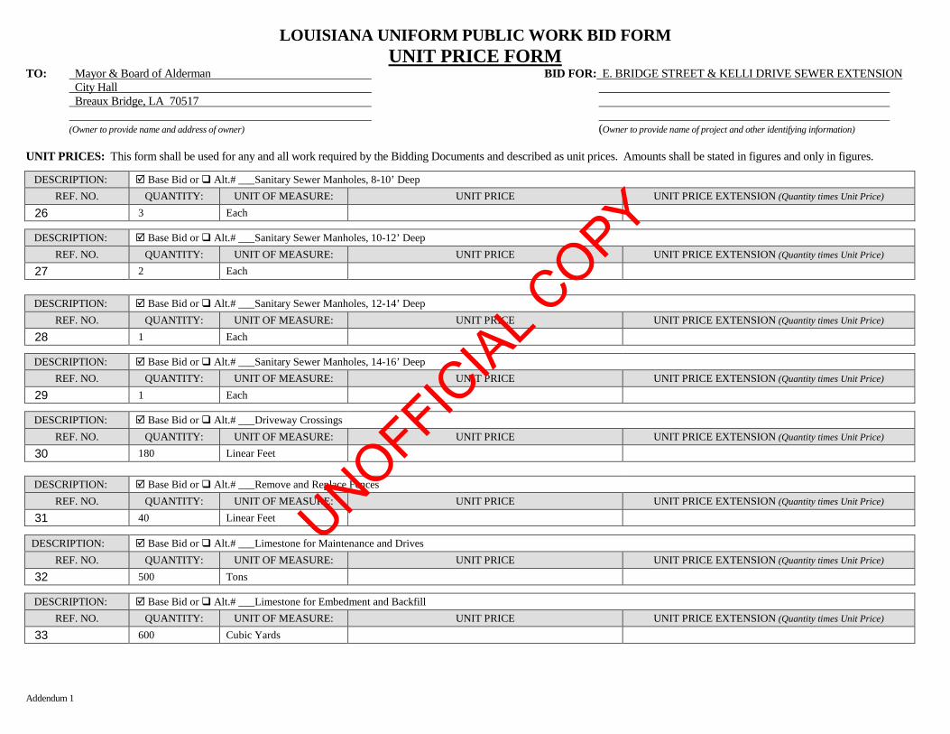
Addendum 1
LOUISIANA UNIFORM PUBLIC WORK BID FORM UNIT PRICE FORM
TO: Mayor & Board of Alderman BID FOR: E. BRIDGE STREET & KELLI DRIVE SEWER EXTENSION City Hall Breaux Bridge, LA 70517
(Owner to provide name and address of owner) (Owner to provide name of project and other identifying information) UNIT PRICES: This form shall be used for any and all work required by the Bidding Documents and described as unit prices. Amounts shall be stated in figures and only in figures. DESCRIPTION: þ Base Bid or q Alt.# ___Sanitary Sewer Manholes, 8-10’ Deep
REF. NO. QUANTITY: UNIT OF MEASURE: UNIT PRICE UNIT PRICE EXTENSION (Quantity times Unit Price) 26 3 Each
DESCRIPTION: þ Base Bid or q Alt.# ___Sanitary Sewer Manholes, 10-12’ Deep REF. NO. QUANTITY: UNIT OF MEASURE: UNIT PRICE UNIT PRICE EXTENSION (Quantity times Unit Price)
27 2 Each
DESCRIPTION: þ Base Bid or q Alt.# ___Sanitary Sewer Manholes, 12-14’ Deep REF. NO. QUANTITY: UNIT OF MEASURE: UNIT PRICE UNIT PRICE EXTENSION (Quantity times Unit Price)
28 1 Each
DESCRIPTION: þ Base Bid or q Alt.# ___Sanitary Sewer Manholes, 14-16’ Deep REF. NO. QUANTITY: UNIT OF MEASURE: UNIT PRICE UNIT PRICE EXTENSION (Quantity times Unit Price)
29 1 Each
DESCRIPTION: þ Base Bid or q Alt.# ___Driveway Crossings REF. NO. QUANTITY: UNIT OF MEASURE: UNIT PRICE UNIT PRICE EXTENSION (Quantity times Unit Price)
30 180 Linear Feet DESCRIPTION: þ Base Bid or q Alt.# ___Remove and Replace Fences
REF. NO. QUANTITY: UNIT OF MEASURE: UNIT PRICE UNIT PRICE EXTENSION (Quantity times Unit Price) 31 40 Linear Feet
DESCRIPTION: þ Base Bid or q Alt.# ___Limestone for Maintenance and Drives REF. NO. QUANTITY: UNIT OF MEASURE: UNIT PRICE UNIT PRICE EXTENSION (Quantity times Unit Price)
32 500 Tons
DESCRIPTION: þ Base Bid or q Alt.# ___Limestone for Embedment and Backfill REF. NO. QUANTITY: UNIT OF MEASURE: UNIT PRICE UNIT PRICE EXTENSION (Quantity times Unit Price)
33 600 Cubic Yards
UNOFFICIA
L COPY
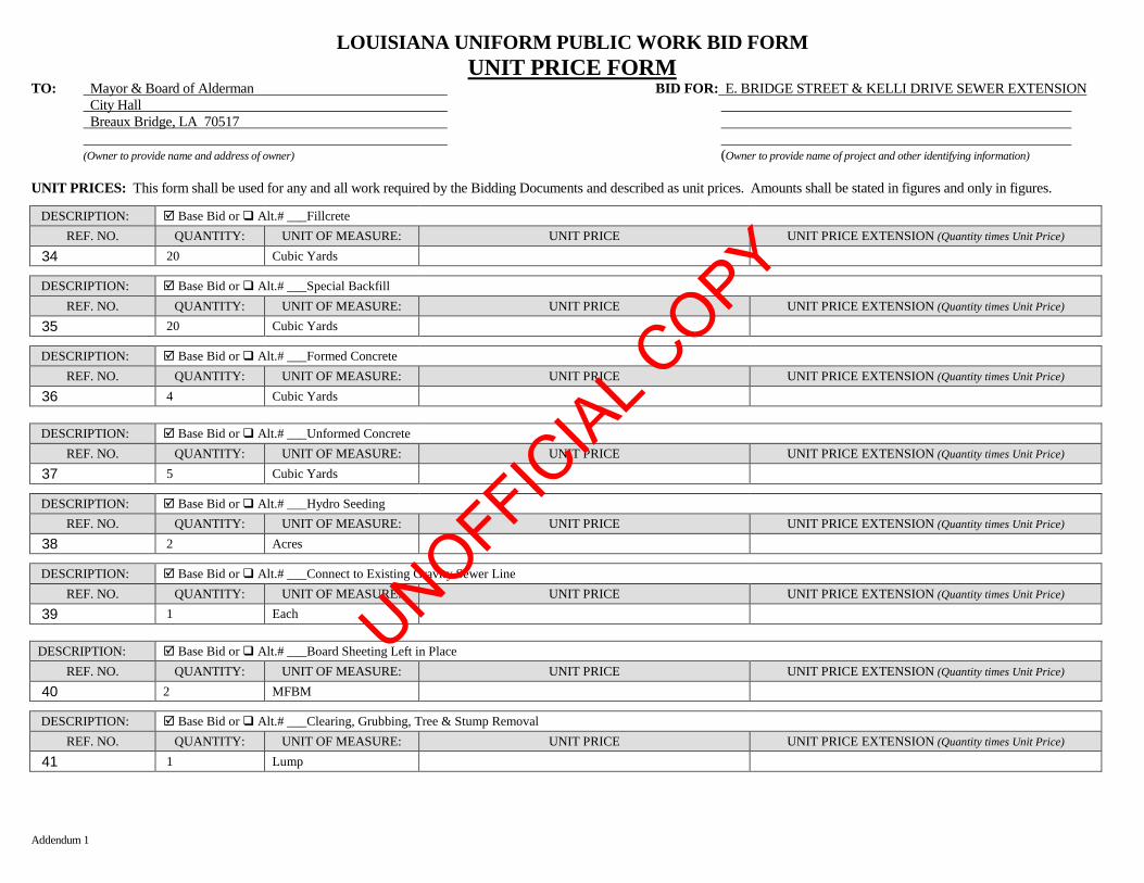
Addendum 1
LOUISIANA UNIFORM PUBLIC WORK BID FORM UNIT PRICE FORM
TO: Mayor & Board of Alderman BID FOR: E. BRIDGE STREET & KELLI DRIVE SEWER EXTENSION City Hall Breaux Bridge, LA 70517
(Owner to provide name and address of owner) (Owner to provide name of project and other identifying information) UNIT PRICES: This form shall be used for any and all work required by the Bidding Documents and described as unit prices. Amounts shall be stated in figures and only in figures. DESCRIPTION: þ Base Bid or q Alt.# ___Fillcrete
REF. NO. QUANTITY: UNIT OF MEASURE: UNIT PRICE UNIT PRICE EXTENSION (Quantity times Unit Price) 34 20 Cubic Yards
DESCRIPTION: þ Base Bid or q Alt.# ___Special Backfill REF. NO. QUANTITY: UNIT OF MEASURE: UNIT PRICE UNIT PRICE EXTENSION (Quantity times Unit Price)
35 20 Cubic Yards
DESCRIPTION: þ Base Bid or q Alt.# ___Formed Concrete REF. NO. QUANTITY: UNIT OF MEASURE: UNIT PRICE UNIT PRICE EXTENSION (Quantity times Unit Price)
36 4 Cubic Yards DESCRIPTION: þ Base Bid or q Alt.# ___Unformed Concrete
REF. NO. QUANTITY: UNIT OF MEASURE: UNIT PRICE UNIT PRICE EXTENSION (Quantity times Unit Price) 37 5 Cubic Yards
DESCRIPTION: þ Base Bid or q Alt.# ___Hydro Seeding REF. NO. QUANTITY: UNIT OF MEASURE: UNIT PRICE UNIT PRICE EXTENSION (Quantity times Unit Price)
38 2 Acres
DESCRIPTION: þ Base Bid or q Alt.# ___Connect to Existing Gravity Sewer Line REF. NO. QUANTITY: UNIT OF MEASURE: UNIT PRICE UNIT PRICE EXTENSION (Quantity times Unit Price)
39 1 Each
DESCRIPTION: þ Base Bid or q Alt.# ___Board Sheeting Left in Place REF. NO. QUANTITY: UNIT OF MEASURE: UNIT PRICE UNIT PRICE EXTENSION (Quantity times Unit Price)
40 2 MFBM
DESCRIPTION: þ Base Bid or q Alt.# ___Clearing, Grubbing, Tree & Stump Removal REF. NO. QUANTITY: UNIT OF MEASURE: UNIT PRICE UNIT PRICE EXTENSION (Quantity times Unit Price)
41 1 Lump
UNOFFICIA
L COPY
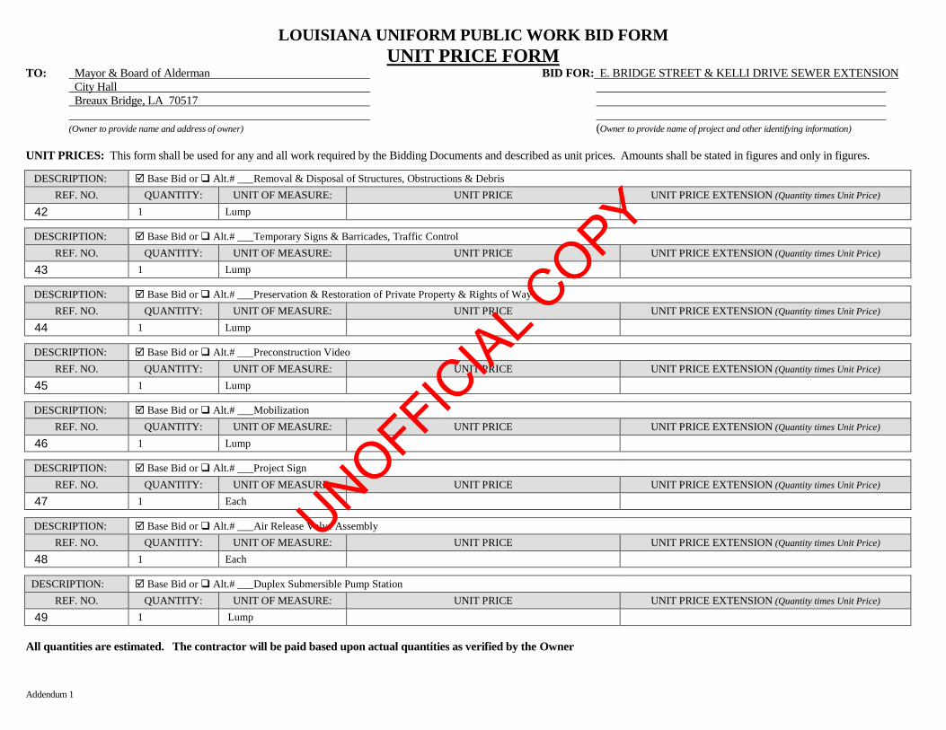
Addendum 1
LOUISIANA UNIFORM PUBLIC WORK BID FORM UNIT PRICE FORM
TO: Mayor & Board of Alderman BID FOR: E. BRIDGE STREET & KELLI DRIVE SEWER EXTENSION City Hall Breaux Bridge, LA 70517
(Owner to provide name and address of owner) (Owner to provide name of project and other identifying information) UNIT PRICES: This form shall be used for any and all work required by the Bidding Documents and described as unit prices. Amounts shall be stated in figures and only in figures. DESCRIPTION: þ Base Bid or q Alt.# ___Removal & Disposal of Structures, Obstructions & Debris
REF. NO. QUANTITY: UNIT OF MEASURE: UNIT PRICE UNIT PRICE EXTENSION (Quantity times Unit Price) 42 1 Lump
DESCRIPTION: þ Base Bid or q Alt.# ___Temporary Signs & Barricades, Traffic Control REF. NO. QUANTITY: UNIT OF MEASURE: UNIT PRICE UNIT PRICE EXTENSION (Quantity times Unit Price)
43 1 Lump
DESCRIPTION: þ Base Bid or q Alt.# ___Preservation & Restoration of Private Property & Rights of Way REF. NO. QUANTITY: UNIT OF MEASURE: UNIT PRICE UNIT PRICE EXTENSION (Quantity times Unit Price)
44 1 Lump
DESCRIPTION: þ Base Bid or q Alt.# ___Preconstruction Video REF. NO. QUANTITY: UNIT OF MEASURE: UNIT PRICE UNIT PRICE EXTENSION (Quantity times Unit Price)
45 1 Lump
DESCRIPTION: þ Base Bid or q Alt.# ___Mobilization REF. NO. QUANTITY: UNIT OF MEASURE: UNIT PRICE UNIT PRICE EXTENSION (Quantity times Unit Price)
46 1 Lump
DESCRIPTION: þ Base Bid or q Alt.# ___Project Sign REF. NO. QUANTITY: UNIT OF MEASURE: UNIT PRICE UNIT PRICE EXTENSION (Quantity times Unit Price)
47 1 Each
DESCRIPTION: þ Base Bid or q Alt.# ___Air Release Valve Assembly REF. NO. QUANTITY: UNIT OF MEASURE: UNIT PRICE UNIT PRICE EXTENSION (Quantity times Unit Price)
48 1 Each
DESCRIPTION: þ Base Bid or q Alt.# ___Duplex Submersible Pump Station REF. NO. QUANTITY: UNIT OF MEASURE: UNIT PRICE UNIT PRICE EXTENSION (Quantity times Unit Price)
49 1 Lump All quantities are estimated. The contractor will be paid based upon actual quantities as verified by the Owner
UNOFFICIA
L COPY
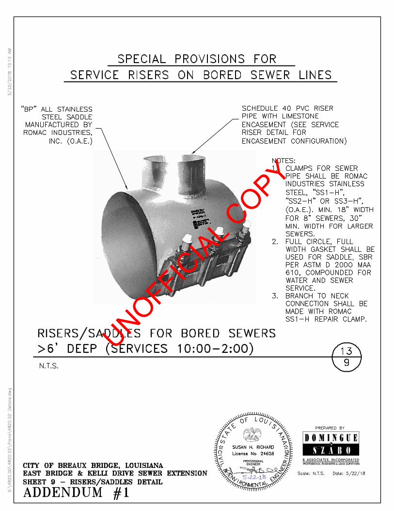
5̂-22-18
UNOFFICIA
L COPY