addendum #1 - 05-21-19 - moteassociates.com · page 2 of 2 addendum no. 1 darke co. commissioners...
TRANSCRIPT

Page 1 of 2 Addendum No. 1Darke Co. Commissioners – Courthouse Security Entrance Addition
ADDENDUM NO.1
Board of Darke County Commissioners Courthouse Security Entrance Addition
May 21, 2019
To: Planholders From: Mote & Associates, Inc. Phone: (937) 548-7511 214 West Fourth Street Fax: (937) 548-7484 Greenville, Ohio 45331 E-mail: [email protected] Re: Board of Darke County Commissioners Courthouse Security Entrance Addition This Addendum forms a part of the Contract Documents and modifies the original Contract Documents dated May 1, 2019. Acknowledge receipt of this Addendum in the space provided on the Bid Proposal form. Failure to do so may subject the Bidder to disqualification. CHANGES/CLARIFICATIONS TO THE TECHNICAL SPECIFICATIONS: 1. ALUMINUM-FRAMED ENTRANCES AND STOREFRONTS, SECTION 08 41 13 a. In Article 2.04.A.1, change “Level 3” to read “Level 7”. CHANGES/CLARIFICATIONS TO THE CONSTRUCTION DRAWINGS: 2. SHEET C1-01, SITE UTILIZATION PLAN
a. Add the following note immediately inside the building on the wall to the southeast of the front basement entrance doors: Repair approximately 12 inches square opening in the wall glazed tile to match the existing wall. The Owner will furnish the glazed tile for installation.
3. SHEET G2-01, EXTERIOR ELEVATIONS AND ROOF PLAN
a. Change the quantity and locations of 3 control joints center on the windows designated with Keynote 38 to 2 control joints centered between the windows. Also make this same change to the same control joints shown on Drawing G1-01 and designated there by keynote 29.
4. SHEET E0-01, ELECTRICAL NOTES, SCHEDULES, AND DIAGRAMS
a. On the Electrical Legend, add the following after the symbol for Door Contact. Door contact shall be balanced magnetic switch complying with UL 634, installed on the frame with integral overcurrent device to limit current to 80 percent of switch capacity. Bias magnet and minimum of two encapsulated reed switches shall resist compromise from detection of foreign magnetic fields. Provide door contacts by Honeywell, Amseco, FBII, GE Interlogix, GRI, or DSC. All wiring shall meet recommendations of the door contact manufacturer and shall be in raceway.

Page 2 of 2 Addendum No. 1Darke Co. Commissioners – Courthouse Security Entrance Addition
5. SHEET E2-01, ELECTRICAL SYSTEMS PLAN
a. On the Basement and First Floor, change the raceway pathways through the existing building to be as shown on attached sketches SK-E2-01-A and SK-E2-01-B.
b. In Electrical Systems Plan Keynote 2, change “500” to “700”. GENERAL CLARIFICATIONS: 6. Change the Title of Sheet E0-01 from “Electrical Demolition Plan, Notes, Schedules, and Diagrams”
to “Electrical Notes, Schedules, and Diagrams” 7. The Report and the Sign-In Sheet from the Pre-Bid Meeting held on May 17, 2019 are attached. 8. The Geotechnical Exploration Report for the project is attached. This report is for Bidder information
only and is not part of the Contract Documents.
End of Addendum
Attachments: Pre-Bid Meeting Notes & Sign-In Sheet Sketch SK-E2-01-A
Sketch SK-E2-01-B Geotechnical Exploration Report

Page | 1
Serving your engineering and surveying needs since 1972
BOARDOFDARKECOUNTYCOMMISSIONERSCOURTHOUSESECURITYENTRANCEADDITION
PRE‐BIDMEETINGNOTESFriday,May17,2019at10:00AM
1. Introductions
Refer to attached Attendance Sheet. 2. Bid Date: Wednesday May 29, 2019.
Bids are due at 1:00 P.M. at Darke County Commissioner’s Office, 520 S. Broadway, Greenville, Ohio 45331.
The Darke County Commissioners will publicly open bids in session at 1:30 P.M.
Bids will be accepted only from registered plan holders who have purchased Bid Documents from Mote & Associates.
The project requires a bid bond and 100% performance bond in accordance with Ohio Revised Code requirements for public bidding.
3. Addendums
The last addendum will be issued not later than 72 hours prior to bid.
Addendum #1 is anticipated to be issued by May 22. 4. The project is subject to State Prevailing Wage requirements as included in the Contract
Documents Manual. 5. Contract
Bids shall remain valid for 60 days.
The project is anticipated to be awarded by mid‐June.
Owner has the right to accept or reject any/all bids. 6. Completion Date: December 15, 2019. 7. Bid Alternates and allowances:
Alternate No. 1 is an Add for extension of the secondary electrical service (award to be determined by the Owner in conjunction with DP&L).
Alternate No. 2 is a Deduct for allowing completion date extension to March 1, 2020.
Include $10,000.00 Hardware Allowance in the Base Bid.
Include $7,500.00 Contingency Allowance in the Base Bid.
Allowance amounts are for actual direct cost only. Markup, overhead, and profit on allowance amounts are to be included in the Base Bid. Refer to Section 01 21 00 for full description of Allowances.
8. This is a Single Prime Contractor project.
Bidders shall include all subcontractor costs in their Bids and include the Proposed Subcontractors Form with the Bid Packet.
9. Insurance requirements are specified in the Supplementary Conditions.

Page | 2
10. Owner supplied materials:
The Owner will furnish a Plaque and Time Capsule for Contractor installation. 11. The Owner will have separate vendor contracts ongoing during project construction.
Security cameras and camera cabling. 12. Modifications or clarifications to the following are currently intended known items for
Addendum #1:
Adjust masonry control joint locations.
Increase resistance level of bullet resistant glass between Vestibule and Security Check Room.
Clarify door contact products. 13. Bidder Questions are to be submitted by email to Don Miller at [email protected] 14. Site Utilization Plan Drawing C1‐01 was discussed in general relative to notes on the
Drawing. 15. Building appearance matching is very important. The cast stone selections specified are
a good color match. 16. Work in the existing building is minimal and consists primarily of:
Installation and removal of a temporary interior ramp on the basement level at the front entrance.
A new permanent ramp in the basement at the new rear addition.
Connection to and extension of existing restroom exhausts.
Connection of the new water service piping to the existing water meter.
Connection to and extension of the fire alarm system.
Installation of door contacts, wiring, and alarms at the basement and first floor front entrances.
Installation of two 2‐inch conduits from the addition to the surveillance camera central equipment.
A new cabinet in the treasurer’s office.
Exit signage at the doors connecting to the new addition. 17. Individual Bidder site visits may be scheduled by contacting Carl McCullough, Darke
County Facility and Safety Manager, 937‐547‐7302, [email protected] 18. A tour of facility followed the pre‐bid meeting.
BIDDER QUESTIONS AND RESPONSES
1. What does the limited time work of Keynote 13 on Drawing C1‐01 apply to? Response: The keynote applies to the site work outside of the construction fence shown on Drawing C1‐01; primarily to the sidewalk and under‐sidewalk work along West Fourth Street and to the sidewalk, pavement repair and underground conduit installation work shown at the back of the County Administration Building parking lot.
2. Are Special Inspections required and, if so, how are they to be handled? Response: The left‐hand side of Drawing S0‐01 Lists the Special Inspection activity that will be required. The Special Inspection agency will be retained directly by the Owner. Contractor responsibilities will be to schedule and cooperate with the Special Inspection Agency and to reimburse the owner for the cost of any retesting required due to failure of initial tests.


X
X
XX
XX
XX
SCALE:
DATE:DRAWN: CHECKED:
PROJ. NO: DWG. NO:
SHEET NO:
Mot e& AssociatesEngineering, Land Surveying
REVISIONS:
Address: 214 W. Fourth St., Greenville, OH 45331
Phone: 937.548.7511
Website: www.moteassociates.comCRM DRM
SK-E2-01-A
1/16" = 1'-0"
05/21/19
GR04011619
DARKE COUNTY BOARD OF COMMISSIONERS
COURTHOUSE SECURITY ENTRANCE ADDITION
ELECTRICAL SYSTEMS PLAN
SCALE: 1/16" = 1'-0"
BASEMENT FLOOR PLAN
UP
UP
MEN'S
R.R.
WOMEN'S
R.R.
CLOSET
BOILER
ROOM
ELECTRICAL
CONFERENCE
ROOM
CORRIDOR
CLOSET
OFFICE
OPEN
OFFICE
CLOSET
OPEN
OFFICE
OPEN
OFFICE
CORRIDOR
ELEVATOR
OPEN
OFFICE
1710
2
724
DC
7 15
15 18
15 18
NOTE:
PAINT ALL EXPOSED RACEWAYS
TO MATCH ADJACENT SURFACE.

X
X
XX
X
XX
X
SCALE:
DATE:DRAWN: CHECKED:
PROJ. NO: DWG. NO:
SHEET NO:
Mot e& AssociatesEngineering, Land Surveying
REVISIONS:
Address: 214 W. Fourth St., Greenville, OH 45331
Phone: 937.548.7511
Website: www.moteassociates.comCRM DRM
SK-E2-01-B
1/16" = 1'-0"
05/21/19
GR04011619
DARKE COUNTY BOARD OF COMMISSIONERS
COURTHOUSE SECURITY ENTRANCE ADDITION
ELECTRICAL SYSTEMS PLAN
SCALE: 1/16" = 1'-0"
FIRST FLOOR PLAN
UP
DOWN
DOWN UP
DOWN
OFFICE
OPEN
OFFICE
OPEN
OFFICE
OPEN
OFFICE
SAFE SAFE
OPEN
OFFICE
OPEN
OFFICE
OFFICE
BREAK
ROOM
RECORDS
STORAGE
RECORDS
STORAGE
RECORDS
STORAGE
OPEN
OFFICE
OFFICE
CORRIDORCORRIDOR
ELEVATOR
WAITING
AREA
WAITING
AREA
WAITING
AREA
WAITING
AREA
2
1710
7
24
DC
7
DRILL TRIM TO
CONCEAL CONDUIT
3/4" EMT
IN EXISTING
SOFFIT
NOTE:
PAINT ALL EXPOSED RACEWAYS
TO MATCH ADJACENT SURFACE.

CTL Engineering, Inc. 102 Commerce Dr, Wapakoneta, Ohio 45895
Phone: 419/738-1447 • Fax: 419/738*7670 AN EMPLOYEE OWNED COMPANY Consulting Engineers • Testing • Inspection Services • Analytical Laboratories Established 1927
April 8, 2019 Mote & Associates, Inc. 214 West Fourth Street Greenville, Ohio 45331 Attention: Mr. Michael W. Henderson, LEED GA Reference: Geotechnical Exploration Report
Darke County Courthouse Rear Security Addition S. Broadway Street & W. Fourth Street Greenville, Ohio - Darke County
CTL Project No. 19050009WAP Mr. Henderson: CTL Engineering, Inc. (CTL) has completed the geotechnical exploration report for the above referenced project. An electronic copy (PDF file) of the geotechnical exploration report has been provided. CTL’s report is based on preliminary design information along with assumptions for the facility. If this information has been revised, or if the assumptions are incorrect, CTL should be provided the updated information for review and our recommendations revised, if necessary. Thank you for the opportunity to be of service to you on this project. If you have any questions, please contact our office. Respectfully Submitted, CTL ENGINEERING, INC.
Frederick Schoen, P.E. Project Manager

GEOTECHNICAL EXPLORATION REPORT
DARKE COUNTY COURTHOUSE REAR SECURITY BUILDING ADDITION
GREENVILLE, DARKE COUNTY, OHIO
CTL PROJECT NO. 19050009WAP
PREPARED FOR:
MOTE & ASSOCIATES, INC. 214 WEST FOURTH STREET GREENVILLE, OHIO 45331
PREPARED BY:
CTL ENGINEERING, INC. 102 COMMERCE DR.
WAPAKONETA, OH 45895
APRIL 8, 2019

Geotechnical Exploration Report April 8, 2019 Darke County Courthouse Addition CTL Project No. 19050009WAP Greenville, Darke County, Ohio Page i
TABLE OF CONTENTS PAGE
I. PROJECT LOCATION AND INFORMATION ............................................................... 1
II. SUBSURFACE EXPLORATION ....................................................................................... 1
III. FINDINGS ............................................................................................................................. 2
A. Observations ................................................................................................................ 2
B. Geology......................................................................................................................... 2
C. Subsurface Conditions ................................................................................................ 2
IV. DISCUSSION AND EVALUATION .................................................................................. 4
A. Fill Materials ............................................................................................................... 4
B. Marginal Foundation Bearing Soils .......................................................................... 5
C. Reuse of Excavated Materials as Engineered Fill .................................................... 5
D. Ground Water ............................................................................................................. 5
V. ANALYSIS AND RECOMMENDATIONS ....................................................................... 6
A. Site Preparation and Earthwork Recommendations .............................................. 6
B. Foundation Support Recommendations ................................................................... 8
C. Slab on Grade Design ................................................................................................. 9
D. Estimated Settlement ................................................................................................ 10
E. Seismic Site Class Recommendation ....................................................................... 10
VI. CHANGED CONDITIONS ............................................................................................... 10
VII. TESTING AND OBSERVATION..................................................................................... 11
VIII. CLOSING ........................................................................................................................... 11
APPENDIX A BORING LOCATION PLAN
APPENDIX B TEST BORING RECORDS / SOIL PROFILE SHEET
APPENDIX C RESULTS OF SOIL LABORATORY TESTS

Geotechnical Exploration Report April 8, 2019 Darke County Courthouse Addition CTL Project No. 19050009WAP Greenville, Darke County, Ohio Page 1
I. PROJECT LOCATION AND INFORMATION
It is understood that the Darke County Board of Commissioners are in the planning stages for the design and construction of a building addition onto the existing Darke County Courthouse in Greenville, Darke County, Ohio. The addition is understood to be located at the rear (southwest) side of the courthouse and will be used as additional security for the courthouse. It is understood that the proposed structure will likely be single-story with approximately 18 feet tall load-bearing masonry walls supported by cast-in-place concrete wall spread footings and that loads applied to footings will not exceed 5 kips/ft.
II. SUBSURFACE EXPLORATION
On March 14, 2019, Envirocore Ltd., under the direction and supervision of CTL Engineering, Inc. (CTL), drilled and sampled two (2) soil test borings, designated as B-01-19 and B-02-19, within close proximity of the footprint of the proposed building addition. The boring locations are presented on the boring location plan enclosed in Appendix A. The test borings were drilled to a depth of 20 feet below ground surface (bgs). The boring locations were selected by Mote & Associates (Mote) and located in the field by CTL. Boring locations were offset from their intended location in the field in order to avoid buried underground utilities. The ground surface elevations at boring locations were estimated from the site location plan prepared by Mote. The test borings were drilled utilizing 3¼ inch I.D. hollow-stem augers powered by a track-mounted drill rig. Split-barrel (spoon) samples and Standard Penetration Tests (SPTs) were conducted in the test borings using a 140-pound automatic hammer falling 30 inches to drive a 2-inch O.D. split-barrel sampler for 18 inches in accordance with ASTM D1586. The split spoon sampling and SPTs were performed at 2½-foot or 5-foot intervals. The soil material recovered from the split-spoon sampler obtained during the drilling operations were preserved in glass jars, visually classified in the field, and delivered to CTL’s soil laboratory for further classification, testing and analysis. All samples were tested for natural moisture content. Representative samples were subjected to laboratory testing including Atterberg Limits, and particle size analysis. The results of these tests are presented in Appendix C and are summarized in Section III. Findings. Drilling, sampling, field and laboratory testing were performed in accordance with standard geotechnical engineering practices and current ASTM procedures. Results from field and laboratory tests are shown on the enclosed test boring records in Appendix B. The results of the laboratory tests are presented in Appendix C.

Geotechnical Exploration Report April 8, 2019 Darke County Courthouse Addition CTL Project No. 19050009WAP Greenville, Darke County, Ohio Page 2
III. FINDINGS
A. Observations
The proposed building addition will be located at the rear (southwest) side of the existing courthouse building. Access to the existing building on this side is by concrete steps that lead both up and down to exterior doors at different floors of the building. The existing project area within the proposed building footprint is currently covered by concrete sidewalk and asphalt pavement. The subject area is relatively flat, with a slight slope for drainage to the storm sewer system. At the time of CTL’s site visit, several underground utilities were noted within 10 feet of the existing building.
B. Geology
According to the Web Soil Survey: Darke County, Ohio, United States Department of Agriculture, Natural Resources Conservation Service, the surficial soils at the project site are identified as Crosby silt loam, Southern Ohio Till Plain, 0 to 2 percent slopes (CrA). These soils are described as having a moderate risk of corrosion of concrete and a high risk of corrosion of uncoated steel. According to the mapping of bedrock geology in the area, (Bedrock Geologic Map of Ohio, ODNR Geological Survey, Map BG-1, 2006), the surficial soil deposits on the site are underlain by Silurian-age sedimentary rock identified as Lockport Dolomite. This formation consists of dolomite described as shades of white to medium gray, medium to massive bedded, fine to coarse crystalline; fossiliferous; vuggy.
Mapping of bedrock topography (Bedrock Topography of the Greenville West, Ohio Quadrangle, ODNR Geological Survey, Digital Map Series BT-B5D2, Revised 1999) indicates the elevation of the top of rock surface in the project area ranges from about 900 to 950 feet. The ground surface elevation in the project area is approximately 1045± feet. These elevations indicate the depth of rock is about 120± feet bgs. It should be noted that the referenced mapping utilizes 50-foot contours that are interpolated from topographic surface features and widely spaced data points where water wells and previous borings have encountered rock.
C. Subsurface Conditions
A general description of the materials encountered is provided below. Further details of the subsurface conditions encountered during CTL’s geotechnical exploration are presented on the test boring records in Appendix B. Results of the soil laboratory tests are presented in Appendix C.

Geotechnical Exploration Report April 8, 2019 Darke County Courthouse Addition CTL Project No. 19050009WAP Greenville, Darke County, Ohio Page 3
1. Surface Cover Materials
Test boring B-01-19 was drilled within a landscaped island surrounded by concrete sidewalk and encountered 6 inches of mulch and topsoil at the ground surface. Test boring B-02-19 was drilled within the parking lot and encountered 4 inches of asphalt over 6 inches of granular base material.
2. Fill Materials
Beneath the surface cover materials, test boring B-02-19 encountered fill materials to a depth of approximately 3.0 feet below the ground surface (bgs). The fill material was described as very stiff, dark gray lean clay (CL), with traces of sand and gravel. The natural moisture content of the fill material was 18 percent.
3. Fine-Grained Soils
Beneath the surficial materials and fill soils, the test borings encountered fine-grained (silt and clay) soils to a depth of about 8.0 feet bgs (elevations 1037.0 and 1037.5 feet). These materials were visually described as medium stiff to very stiff, brown and/or gray, sandy lean clay and sandy lean clay with gravel (CL). The SPT N60-values determined within these moderately plastic fine-grained soils ranged from 7 to 25 blows per foot (bpf). The N60-value is the SPT blow count N-value determined in the field and corrected for the hammer efficiency, delivered by the drill rig hammer system utilized, normalized to 60 percent efficiency in bpf. Both test borings also encountered fine grained soils at a depth of 18.0 feet bgs down to the boring termination depth of 20.0 feet. These materials were visually described as hard, brown or gray, sandy lean clay (CL). In B-01-19, split spoon sampler refusal was encountered, which indicates that the sampler advanced less than 6 inches after 50 blows. In B-02-19, the SPT N60-value determined within this soil layer was 111 bpf. All of the native fine-grained materials were tested for moisture content and a representative sample was selected for additional Atterberg Limits and particle size analysis (gradation) testing. The natural moisture contents of the material ranged from 6 to 25 percent. A representative sample from B-01-19 exhibited a Liquid Limit of 36 and a corresponding plasticity index of 21. This material was classified as CL according to the USCS.
4. Granular Soils
At a depth of 8.0 feet bgs (elevations 1037.0 and 1037.5 feet), borings encountered granular soils down to a depth of about 18.0 feet bgs (elevations 1027.0 and 1027.5 feet). These materials were visually described as medium dense to dense, brown, silty clayey sand (SC-SM). The SPT N60-values determined within these granular soils ranged from 29 to 56 bpf.

Geotechnical Exploration Report April 8, 2019 Darke County Courthouse Addition CTL Project No. 19050009WAP Greenville, Darke County, Ohio Page 4
All of the native granular materials were tested for moisture content and a representative sample was selected for additional Atterberg Limits and particle size analysis (gradation) testing. The natural moisture contents of the material ranged from 8 to 10 percent. A representative sample from B-02-19 exhibited a Liquid Limit of 20 and a corresponding plasticity index of 6. This material was classified as SC-SM according to the USCS.
5. Ground Water
The depths to ground water were recorded during drilling and at the completion of drilling after removing augers and prior to backfilling of the boreholes. The depth to borehole cave-in was also determined prior to backfilling of the boreholes. The boreholes were backfilled immediately subsequent to drilling and field testing operations due to safety concerns; therefore, long-term ground water level readings were not obtained. Ground water was encountered in B-02-19 during drilling at a depth of 17.0 feet bgs, and at completion in B-01-19 at 13.0 feet bgs. Cave-in after auger removal occurred at a depth of 15 feet in B-01-19 and 8.0 feet in B-02-19.
IV. DISCUSSION AND EVALUATION
Based on the results of the sampling, field and laboratory testing; our analysis and evaluation of the data and CTL’s experience with similar soils and types of structures; the site is considered suitable for the support of the building addition. However, conditions were encountered which pose a concern from a geotechnical engineering and construction standpoint. These concerns and their implications are addressed below.
A. Fill Materials
Fill material was encountered in test boring B-02-19 to 3.0 feet below ground surface. The fill consisted of very stiff lean clay. It appears the fill material encountered was placed to prepare the subgrade for the finish grade of the pavement. Although it is not known whether the fill material was originally placed in a controlled manner it appears that compaction effort was applied due to the relative density of the materials encountered. Due to the unknown conditions under which it was placed, it should be assumed that the fill material type, depth and consistency may vary across the site and may differ from the materials encountered in the test borings.

Geotechnical Exploration Report April 8, 2019 Darke County Courthouse Addition CTL Project No. 19050009WAP Greenville, Darke County, Ohio Page 5
B. Marginal Foundation Bearing Soils Marginal medium stiff fine-grained soil was encountered at depths ranging from the ground surface to 5.5 feet bgs in the test borings. These marginal materials are anticipated to be encountered throughout the site. These materials are not suitable for foundation or pavement support, in their current condition, based on their low shear strength. Improvement of the underlying soil materials will be required for typical steel-reinforced, cast-in-place concrete spread foundations bearing at nominal depths. Recommendations for improving these materials are presented in the subsequent sections of this report.
C. Reuse of Excavated Materials as Engineered Fill
Although a final site grading plan has not been developed at this date, CTL assumes that potential engineered fill used on this site will probably be from on-site excavated areas. Excavated soils designated for use as engineered fill must meet the requirements given in Section V.A. Site Preparation and Earthwork Recommendations of this report. Some of the fine-grained soils encountered exhibited natural moisture contents at or above the material’s estimated optimum moisture content and will likely require some moisture conditioning (drying) before being used as engineered fill, especially if the site preparation takes place during periods of wet weather, typically between the months of October to May.
D. Ground Water
Based on our experience with the geology at this site, ground water conditions affecting construction projects are related to trapped or perched water that may occur in irregular, discontinuous zones within the soil overburden such as the sand layers encountered in the test borings, and may also be present but were not identified on the test boring records. When these water bearing strata are exposed in excavations, such as utility or footing trenches, they can produce widely varying seepage durations and rates depending on recent rainfall activity and other hydrogeologic characteristics of the area. Therefore, ground water levels may vary from those measured at the time/date of drilling. These perched water sources are often not linked to the more continuous static groundwater encountered at greater depths. Based on our experience CTL anticipates that ground water may be encountered within trapped zones at shallow depths or within the sand layers if excavations reach that depth. The perched water tends to have a limited volume and lower flow rates which tend to be controlled with conventional dewatering methods and would not require an extensive dewatering plan and/or methods.

Geotechnical Exploration Report April 8, 2019 Darke County Courthouse Addition CTL Project No. 19050009WAP Greenville, Darke County, Ohio Page 6
V. ANALYSIS AND RECOMMENDATIONS
A site grading plan has not been developed at this date. It is unknown if the building addition will be constructed at the ground floor elevation of the existing building, which would require a cut of several feet based on the stairs down from the surrounding grade to the exterior door. Recommendations are provided for assumed finish floor elevations of 1045.0 feet (existing exterior grade), and 1042.0 feet (estimated finish floor elevation of existing building). These elevations result in assumed bottom of foundation elevations of 1042.0 feet and 1039.0 feet, respectively. If after further design development of the building addition and the associated site plan, the grading of the site is different from what CTL has assumed in this report, the information should be provided to CTL for review and the recommendations revised, if necessary. Based upon the preceding considerations as well as the subsurface information obtained from the field and laboratory testing and CTL’s experience with these soil types, the following recommendations are provided. A. Site Preparation and Earthwork Recommendations
The following are general recommendations for site preparation. It should be noted that if earthwork is performed in late autumn to early spring, typical weather conditions in west-central Ohio will result in saturated surficial soils and temperatures that are not high enough to dry the soil expediently. Elevated soil moisture contents for the soil types encountered are not only difficult to reduce but also have a narrow range where they are suitable for compaction. These issues during the site preparation phase of construction should be taken into consideration when evaluating alternatives and their associated costs. 1. Strip the topsoil, concrete, and pavement from the surface of the construction
area within 5 feet beyond the plan construction limits. These materials should be wasted from the site.
2. After excavation to the proposed subgrade elevation (if necessary), and prior to placement of engineered fill and/or aggregate base for the building slab on grade, a proof roll of the subgrade should be performed to delineate soft, yielding or other unsuitable areas that may require stabilization prior to the placement and compaction of engineered fill or base. The proof roll should utilize a fully-loaded, dual-wheeled, tandem axle, dump truck with a total weight on the order 25 tons. The area being proof rolled should be evaluated by slowly driving the loaded dump truck across the entire designated fill area in perpendicular directions. The proof roll should be observed and documented by the Geotechnical Engineer or his designated representative experienced in determining suitable subgrade conditions.

Geotechnical Exploration Report April 8, 2019 Darke County Courthouse Addition CTL Project No. 19050009WAP Greenville, Darke County, Ohio Page 7
3. If stabilization of the subgrade is required, the first alternative would consist of over-excavating the existing soft yielding subgrade a minimum of 12 inches and backfilling the area up to proposed finish subgrade with new properly placed and compacted engineered fill. If the conditions at the proposed undercut elevation are not stable it may be necessary to stabilize the subgrade before placing engineered fill by a) drying and recompacting the material in place; b) placing a layer of multi-axial geogrid followed by 12 inches of crushed granular material such as ODOT Item 304 sized gravel; or c) chemically stabilizing with cement. Finish grade would then be re-established by using properly compacted, engineered soil fill.
4. If the use of chemical stabilization is preferred in order to stabilize the
building pad area, the depth of the stabilization should be a minimum depth of 12 inches below the proposed final subgrade elevation. For the purpose of a preliminary cost estimate, the amount of cement used for soil modification may be assumed to be about 5 or 7 percent, respectively, by weight. Laboratory testing, in accordance with ODOT Item 206 will be required to determine the recommended type of chemical modifier and the amount of chemical modifier to be added to the soil. This testing should be performed by a qualified AMRL accredited laboratory prior to performing the stabilization. It should be noted that chemical stabilization requires ambient air temperatures to be at 40 °F or above in order for the desired results to be achieved.
5. During earthwork operations, maintain positive surface drainage at the end of
each workday to prevent water from ponding on the surface of the exposed soils during construction and as part of final grading. The accumulation of precipitation, absorption of water, and heavy construction traffic may result in the softening of the exposed soils, and as a result, severely reducing the shear strength and therefore stability of the subgrade soils. Contact the Geotechnical Engineer should the subgrade soils become excessively wet, dry, or frozen.
6. Suitable engineered fill material, if required for this project, may consist of the on-site excavated soils provided that the Liquid Limit does not exceed 45 and the Plasticity Index of less than 25, and that proper moisture content is maintained during their placement. The on-site lean clay soil should meet these requirements.
7. Engineered fill should be placed in layers not to exceed 8 inches in loose thickness, with each layer compacted to 100 percent of the maximum dry density as determined by ASTM D 698 standard method (or AASHTO T-99), or as otherwise directed by the Geotechnical Engineer. Moisture control should be within ± 3 percent of the optimum moisture content as determined by ASTM D 698 standard method (AASHTO T-99).

Geotechnical Exploration Report April 8, 2019 Darke County Courthouse Addition CTL Project No. 19050009WAP Greenville, Darke County, Ohio Page 8
8. CTL recommends field moisture-density tests be performed within the engineered fill for each lift of fill at a rate of at least one test for an area covering approximately every 10,000 square feet of engineered fill placed and compacted. A minimum of two field moisture-density tests should be performed per each entire lift of engineered fill placed and compacted.
9. Areas that do not meet the specified compaction criteria, based on the testing and observations of the engineering technician observing the earthwork activities and performing the field testing, should be reworked (scarified, moisture conditioned and re-compacted) to a suitable depth and re-tested. If the reworked engineered fill lift does not meet the earthwork specification the Geotechnical Engineer should be contacted to evaluate the current conditions and provide additional recommendations if necessary.
10. The observation and testing of engineered fill should be performed by qualified field personnel, performing the field density testing activities under the supervision of a registered professional engineer who specializes in geotechnical engineering, and is licensed in the State of Ohio.
11. Temporary excavations in excess of 4.0 feet in depth should be sloped or shored in accordance with OSHA regulations.
12. Isolated zones or pockets of trapped water may be encountered at shallow depths in isolated locations. If ground water is encountered, temporary dewatering will be required and sidewall cave-in should be expected.
13. Fill placement should extend beyond the limits of the proposed building and
paved areas a minimum horizontal distance equal to the height of fill or 5 feet, whichever is greater.
B. Foundation Support Recommendations
The following recommendations assume the finished floor elevation will be either 1045.0 feet of 1042.0 feet, with bottom of foundation elevations of 1042.0 feet and 1039.0 feet, respectively.
1. CTL recommends the building be supported by spread foundations bearing on
native soils consisting of very stiff lean clay (CL). 2. Shallow foundation units may be proportioned using an allowable bearing
capacity value not exceeding the values given in the table below. If the higher bearing capacities at greater depths are required, the soil beneath the foundations should be excavated down to the desired elevation and backfilled with lean concrete. These bearing values apply to the total of all design loads, and were computed using a factor of safety of 3.0.

Geotechnical Exploration Report April 8, 2019 Darke County Courthouse Addition CTL Project No. 19050009WAP Greenville, Darke County, Ohio Page 9
Table 2 – Allowable Bearing Capacities
Elevation (feet)
Allowable Bearing Capacity (psf)
1042 to 1039 2,000
1039 to 1037 3,000
Below 1037 4,000
3. CTL recommends that all bearing surfaces be observed and approved by the
Geotechnical Engineer or his/her designated representative. If marginal soft to medium stiff, loose, excessively wet or highly plastic soils are encountered these soils should be undercut and removed and lean concrete placed up to the proposed footing bearing elevation.
4. The spread foundation should be constructed at a minimum depth of 36 inches
below the lowest adjacent exterior grade to offset the effects of frost penetration.
5. Protect foundation support materials exposed in open excavations from
freezing weather, severe drying, and water accumulation.
6. Remove any soils that become unsuitable due to exposure prior to concrete placement.
7. Excavate only the footings that can be placed with concrete the same day.
8. Foundation concrete should completely fill the opened excavation. Forming
the foundations and then backfilling the space behind the forms tends to allow moisture to penetrate and soften bearing level materials which may result in poor foundation performance.
C. Slab on Grade Design
1. CTL has assumed the effective modulus of subgrade reaction available for the surrounding native soils consisting of stiff to very stiff lean clay (CL) or engineered fill materials is 150 pci.
2. CTL recommends that the slab on grade subgrade surface be observed and
approved by the Geotechnical Engineer or his designated representative. If soft, loose, or highly plastic soils are encountered at the proposed subgrade level, these soils should be excavated and replaced with properly compacted engineered fill materials. The depth of the undercut will depend on the specific soil conditions observed by the Geotechnical Engineer or his designated representative.

Geotechnical Exploration Report April 8, 2019 Darke County Courthouse Addition CTL Project No. 19050009WAP Greenville, Darke County, Ohio Page 10
3. Place a minimum 4-inch layer of clean, compacted gravel or crushed stone beneath the slab to enhance support and provide a working base. The actual thickness of the gravel layer should be based on slab design requirements.
4. Keep the crushed stone or gravel moist, but not wet, immediately prior to
grade slab concrete placement to minimize curling of the slab due to differential curing conditions between the top and bottom of the slab.
5. Provide joints in the slabs around columns and along footing supported walls.
D. Estimated Settlement
Based on assumed loadings for similar projects of this magnitude and the materials encountered in the test borings, CTL anticipates that that the maximum total and differential settlements will be less than 1 inch and ½ inch, respectively. This assumes that engineered fill beneath the foundations is properly placed and compacted and the subsequent inspection of the foundation subgrade is observed and approved by the Geotechnical Engineer or his designated representative.
E. Seismic Site Class Recommendation
Based upon Section 1613 of the Ohio Building Code (OBC), Site Class D may be used for seismic design of the project. This Site Class was determined using the information obtained in the preliminary test borings as well as published information in the vicinity of the project site. Should a significant benefit in the design of the building require the determination of the on-site subsurface shear wave velocity for a higher site class designation (e.g. Site Class C), CTL should be consulted for additional discussions on performing Refraction Microtremor (ReMi) shear wave testing for the site in order to achieve a higher Site Class designation.
VI. CHANGED CONDITIONS
The evaluations, conclusions, and recommendations in this report are based on our interpretation of the field and laboratory data obtained during the exploration, our understanding of the project and our experience with similar sites and subsurface conditions using generally accepted geotechnical engineering practices. Although individual test borings are representative of the subsurface conditions at the boring locations on the dates drilled, they are not necessarily representative of the subsurface conditions between boring locations or subsurface conditions during other seasons of the year. In the event that changes in the project are proposed, additional information becomes available, or if it is apparent that subsurface conditions are different from those provided in this report, CTL should be notified so that our recommendations can be modified, if required.

Geotechnical Exploration Report April 8, 2019 Darke County Courthouse Addition CTL Project No. 19050009WAP Greenville, Darke County, Ohio Page 11
VII. TESTING AND OBSERVATION
During the design process, it is recommended that CTL work with the project designer to confirm that the geotechnical recommendations are properly incorporated into the final plans and specifications, and to assist with establishing criteria for the construction observation and testing. CTL is not responsible for independent conclusions, opinions and recommendations made by others based on the data and recommendations provided in this report. It is recommended that CTL be retained to provide construction quality control services on this project. If CTL is not retained for these services, CTL shall assume no responsibility for compliance with the design concepts or recommendations provided.
VIII. CLOSING
The report was prepared by CTL Engineering, Inc. (Consultant) solely for the use of Mote & Associates (Client) in accordance with an executed contract. The Client’s use of or reliance on this report is limited by the terms and conditions of the contract and by the qualifications and limitations stated in the report. It is also acknowledged that the Client’s use of and reliance of this report is limited for reasons which include: actual site conditions that may change with time; hidden conditions, not discoverable within the scope of the assessment, may exist at the site; and the scope of the investigation may have been limited by time, budget and other constraints imposed by the Client. Neither the report, nor its contents, conclusions or recommendations, are intended for the use of any party other than the Client. Consultant and the Client assume no liability for any reliance placed on this report by such party. The rights of the Client under contract may not be assigned to any person or entity, without the consent of the Consultant which consent shall not be unreasonably withheld. This geotechnical report does not address the environmental conditions of the site. The Consultant is not responsible for consequences or conditions arising from facts that were concealed, withheld, or not fully disclosed at the time the assessment was conducted. To the fullest extent permitted by law, the Consultant and Client agree to indemnify and hold each other, and their officers and employees harmless from and against claims, damages, losses and expenses arising out of unknown or concealed conditions. Furthermore, neither the Consultant nor its employees shall be liable to the Owner in an amount in excess of the available professional liability insurance coverage of the Consultant. In addition, Client and Consultant agree neither shall be liable for any special, indirect or consequential damages of any kind or nature.

Geotechnical Exploration Report April 8, 2019 Darke County Courthouse Addition CTL Project No. 19050009WAP Greenville, Darke County, Ohio Page 12
The Consultant’s services have been provided consistent with its professional standard of care. No other warranties are made, either expressed or implied. Respectfully Submitted, CTL ENGINEERING, INC.
Josh Williams Project Engineer
Frederick Schoen, P.E. Project Manager

APPENDIX A
BORING LOCATION PLAN

Date
3/26/2019
CTL ENGINEERING, INC. Scale
GEOTECHNICAL ENGINEERS None
TESTING * INSPECTION Drawn By Reviewed By Page Project No.
LABORATORY SERVICES FS 1 of 1 19050009WAP
Greenville, OH - Darke County
BORING LOCATION PLANMote & Associates
Darke County Courthouse Security AdditionSouth Broadway Street

APPENDIX B
BORING TEST RECORDS / SOIL PROFILE SHEET
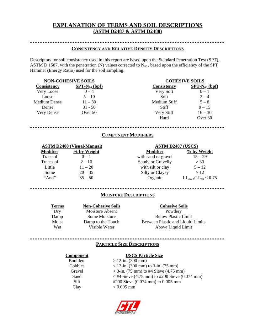
EXPLANATION OF TERMS AND SOIL DESCRIPTIONS(ASTM D2487 & ASTM D2488)
CONSISTENCY AND RELATIVE DENSITY DESCRIPTIONS
Descriptors for soil consistency used in this report are based upon the Standard Penetration Test (SPT),ASTM D 1587, with the penetration (N) values corrected to N60 , based upon the efficiency of the SPTHammer (Energy Ratio) used for the soil sampling.
NON-COHESIVE SOILS COHESIVE SOILSConsistency SPT-N60 (bpf) Consistency SPT-N60 (bpf)Very Loose 0 – 4 Very Soft 0 – 1
Loose 5 – 10 Soft 2 – 4Medium Dense 11 – 30 Medium Stiff 5 – 8
Dense 31 - 50 Stiff 9 – 15Very Dense Over 50 Very Stiff 16 – 30
Hard Over 30
COMPONENT MODIFIERS
ASTM D2488 (Visual-Manual) ASTM D2487 (USCS)Modifier % by Weight Modifier % by WeightTrace of 0 – 1 with sand or gravel 15 – 29Traces of 2 – 10 Sandy or Gravelly ≥ 30
Little 11 – 20 with silt or clay 5 – 12Some 20 – 35 Silty or Clayey > 12“And” 35 – 50 Organic LLoven/LLair < 0.75
MOISTURE DESCRIPTIONS
Terms Non-Cohesive Soils Cohesive SoilsDry Moisture Absent Powdery
Damp Some Moisture Below Plastic LimitMoist Damp to the Touch Between Plastic and Liquid LimitsWet Visible Water Above Liquid Limit
PARTICLE SIZE DESCRIPTIONS
Component USCS Particle SizeBoulders ≥ 12-in. (300 mm)Cobbles < 12-in. (300 mm) to 3-in. (75 mm)Gravel < 3-in. (75 mm) to #4 Sieve (4.75 mm)Sand < #4 Sieve (4.75 mm) to #200 Sieve (0.074 mm)Silt #200 Sieve (0.074 mm) to 0.005 mm
Clay < 0.005 mm

0
10
20
30
40
50
60
0 10 20 30 40 50 60 70 80 90 100 110
PL
AS
TIC
ITY
IN
DE
X
LIQUID LIMIT
"A" LINE GRAPH
CL-ML
CL or OL
ML or OL
MH or OH
CH or OH
4
7

0.5
5.5
8.0
18.0
20.0
SS-1
SS-2
SS-3
SS-4
SS-5
SS-6
100
100
100
100
100
100
3.0*
1.0*
3.5*
5.0*
5.0*
25
22
17
10
10
6
36 15 21
TOPSOIL / MULCH (6")
Medium Stiff to Stiff, Brown, SANDY LEAN CLAY(CL), Traces of Gravel, Moist
Very Stiff, Brown with Gray, SANDY LEAN CLAYwith GRAVEL (CL), Damp
Dense, Brown, SILTY CLAYEY SAND (SC-SM),Little to Traces of Gravel, with Shale Fragmentsand Cobbles, Damp
Hard, Gray, SANDY LEAN CLAY (CL), Little toTraces of Gravel, with Shale Fragments andCobbles, Damp
Bottom of Boring at 20 ft.
123
334
2415
42022
71420
2550-5"
1045.0
1040.0
1037.5
1027.5
1025.5
7
9
25
56
45
03-14-19
03-14-19
:
:
1045.5 Feet
40.100279
-84.631998
20.0 Feet
HSA
:
:
:
:
:
Envirocore
50's F
P. Cloudy
RIG TYPE
CASING DIA.
CORE SIZE
HAMMER
ENERGY RATIO
:
:
:
:
:
:
:
:
Greenville, OH
19050009WAP
DRILLER
TEMPERATURE
WEATHER
LOCATION
PROJECT NO.
:
:
BORING GeoProbe DT7822
2.25" I.D.
n/a
Automatic
80.0
GROUNDWATER: Encountered at Dry At completion 13.0' Caved in at 15.0'
ELEVATION
LATITUDE
LONGITUDE
DEPTH
BORING METHOD
DATE STARTED
DATE COMPLETED
ATTERBERGLIMITS
RE
CO
VE
RY
(%)
ST
RA
TU
MD
EP
TH
SA
MP
LEN
UM
BE
R
60
TEST BORING RECORD
SP
Tpe
r 6"
N
B-01-19
5
10
15
20
------60
*LLPLPISPTN
1
Normalized to 60% Drill Rod ER
OF
BORING NO.:
SHEET
102 Commerce DriveP.O. Box 44Wapakoneta, Ohio 45895Telephone: 419-738-1447Fax: 419-738-7670Email: [email protected]
ST
RA
TU
ME
LEV
AT
ION
SA
MP
LED
EP
TH
SOIL/MATERIAL DESCRIPTION MO
IST
UR
EC
ON
TE
NT
TO
TA
L U
NIT
WE
IGH
Tpc
f
UN
CO
NF
.C
OM
P.,
ksf
LL PL PI
CLIENT
PROJECT
:
:
Mote & Associates
Darke Co. Courthouse Security Expan.
HSASFARCMDWDHA
------
BORING METHODSSSTCRBS
----
Hollow Stem AugerSolid Flight AugerRock CoringMud DrillingWash DrillingHand Auger
SAMPLING METHOD ABBREVIATIONS
1
Split Spoon SampleShelby Tube SampleRock Core SampleBag Sample
Hand PenetrometerLiquid LimitPlastic LimitPlasticity IndexStandard Penetration TestStandard Penetration
TE
ST
BO
RIN
G -
WA
PA
K 1
9050
009
WA
P.G
PJ
NE
W C
TL
WIT
H N
60.G
DT
4/3
/19

0.8
3.0
5.5
8.0
18.0
20.0
SS-1
SS-2
SS-3
SS-4
SS-5
SS-6
100
100
100
100
100
100
7.5*
3.0*
2.5*
4.0*
3.0*
9.0*
18
22
21
9
8
20 14 6
ASPHALT (4") over BASE (6")
Very Stiff, Dark Gray, LEAN CLAY (CL), Tracesof Sand and Gravel, Slightly Organic, Moist(FILL)
Medium Stiff, Brown and Gray, SANDY LEANCLAY (CL), Traces of Gravel, Moist
Very Stiff, Brown, SANDY LEAN CLAY (CL),Little Gravel, Moistwith Sand Seams
Medium Dense to Dense, SILTY CLAYEY SAND(SC-SM), with Cobbles, Damp
Hard, Brown, SANDY LEAN CLAY (CL), LittleGravel, with Cobbles, Damp
Bottom fo Boring at 20 ft.
6810
233
4215
61210
81320
203449
1044.2
1042.0
1039.5
1037.0
1027.0
1025.0
24
8
23
29
44
111
03-14-19
03-14-19
:
:
1045.0 Feet
40.100111
-84.631948
20.0 Feet
HSA
:
:
:
:
:
EnviroCOre
50's F
P. Cloudy
RIG TYPE
CASING DIA.
CORE SIZE
HAMMER
ENERGY RATIO
:
:
:
:
:
:
:
:
Greenville, OH
19050009WAP
DRILLER
TEMPERATURE
WEATHER
LOCATION
PROJECT NO.
:
:
BORING GeoProbe DT7822
2.25" I.D.
n/a
Automatic
80.0
GROUNDWATER: Encountered at 17.0' At completion Dry Caved in at 8.0'
ELEVATION
LATITUDE
LONGITUDE
DEPTH
BORING METHOD
DATE STARTED
DATE COMPLETED
ATTERBERGLIMITS
RE
CO
VE
RY
(%)
ST
RA
TU
MD
EP
TH
SA
MP
LEN
UM
BE
R
60
TEST BORING RECORD
SP
Tpe
r 6"
N
B-02-19
5
10
15
20
------60
*LLPLPISPTN
1
Normalized to 60% Drill Rod ER
OF
BORING NO.:
SHEET
102 Commerce DriveP.O. Box 44Wapakoneta, Ohio 45895Telephone: 419-738-1447Fax: 419-738-7670Email: [email protected]
ST
RA
TU
ME
LEV
AT
ION
SA
MP
LED
EP
TH
SOIL/MATERIAL DESCRIPTION MO
IST
UR
EC
ON
TE
NT
TO
TA
L U
NIT
WE
IGH
Tpc
f
UN
CO
NF
.C
OM
P.,
ksf
LL PL PI
CLIENT
PROJECT
:
:
Mote & Associates
Darke Co. Courthouse Security Expan.
HSASFARCMDWDHA
------
BORING METHODSSSTCRBS
----
Hollow Stem AugerSolid Flight AugerRock CoringMud DrillingWash DrillingHand Auger
SAMPLING METHOD ABBREVIATIONS
1
Split Spoon SampleShelby Tube SampleRock Core SampleBag Sample
Hand PenetrometerLiquid LimitPlastic LimitPlasticity IndexStandard Penetration TestStandard Penetration
TE
ST
BO
RIN
G -
WA
PA
K 1
9050
009
WA
P.G
PJ
NE
W C
TL
WIT
H N
60.G
DT
4/3
/19

1,024
1,026
1,028
1,030
1,032
1,034
1,036
1,038
1,040
1,042
1,044
1,046
1,024
1,026
1,028
1,030
1,032
1,034
1,036
1,038
1,040
1,042
1,044
1,046
50-5"
25
22
17
10
10
6
7
9
25
56
45
B-01-19
18
22
21
9
8
24
8
23
29
44
111
B-02-19
GW-GC
CL-ML SHALE
SP-SMCORRECTED STANDARDPENETRATION INBLOWS PER FOOT (N60)
SW-SMASPHALT
GW
LIMESTONE
SW-SC ML
FILL
CH
MH
OH
PT GROUND WATER ATCOMPLETION OF DRILLING
N
DRAWN BY
MOISTURE CONTENT INPERCENT (w)
GROUND WATER DURINGDRILLING
Greenville, OHGROUND WATER AT "N"HOURS AFTER COMPLETION
Mote & Associates
102 Commerce DriveP.O. Box 44Wapakoneta, OH 45895Telephone: 419-738-1447Fax: 419-738-7670Email: [email protected]
SILTSTONE
SOIL PROFILE
GP
SC
SC-SM
CLDATE
4/3/2019
PAGE
1 OF 1 19050009WAPPROJECT NUMBER
TOPSOIL
GW-GM
GM
SP
SP-SC
SM-
OL
Darke Co. Courthouse Security Expan.
W
LEGEND
SCALEAS SHOWN
GP-GC
GC-GM
GP-GM
GC
SW

APPENDIX C
RESULTS OF SOIL LABORATORY TESTS

0
5
10
15
20
25
30
35
40
45
50
55
60
65
70
75
80
85
90
95
100
0.0010.010.1110100
%MC
%Gravel
GRAIN SIZE DISTRIBUTION
0.0040.040.091193.5SS-2B-01-19
3/8
SILT OR CLAY
34
Boring No. D30
Depth
D50
Cu
2 403
D10
coarse fine
%Sand
30
U.S. SIEVE OPENING IN INCHES
3/4 14016
medium
1006 8
HYDROMETER
D60
1/21.5
ClassificationSample
60 200
DepthSample
20P
ER
CE
NT
FIN
ER
BY
WE
IGH
T14
U.S. SIEVE NUMBERS
GRAIN SIZE IN MILLIMETERS
D100
CcLL
%Silt
1 10
B-01-19 SS-2 3.5 36 15 21
312
PI
25
6
PL
%Clay
SANDCOBBLES
GRAVELcoarse
Boring No.
4
fine
50
22SANDY LEAN CLAY(CL)
42
Project: Darke Co. Courthouse Security Expan.
Location: Greenville, OH
CTL Project Number: 19050009WAP
CTL Engineering102 Commerce Dr., P.O. Box 44Wapakoneta, OH 45895Telephone: (419) 738-1447Fax: (419) 738-7670
GR
AD
AT
ION
- W
AP
AK
190
5000
9W
AP
.GP
J N
EW
CT
L W
ITH
N60
.GD
T 4
/3/1
9

0
5
10
15
20
25
30
35
40
45
50
55
60
65
70
75
80
85
90
95
100
0.0010.010.1110100
%MC
%Gravel
GRAIN SIZE DISTRIBUTION
0.0160.080.161198.5SS-4B-02-19
3/8
SILT OR CLAY
34
Boring No. D30
Depth
D50
Cu
2 403
D10
coarse fine
%Sand
30
U.S. SIEVE OPENING IN INCHES
3/4 14016
medium
1006 8
HYDROMETER
D60
1/21.5
ClassificationSample
60 200
DepthSample
20P
ER
CE
NT
FIN
ER
BY
WE
IGH
T14
U.S. SIEVE NUMBERS
GRAIN SIZE IN MILLIMETERS
D100
CcLL
%Silt
1 10
B-02-19 SS-4 8.5 20 14 6
175
PI
33
6
PL
%Clay
SANDCOBBLES
GRAVELcoarse
Boring No.
4
fine
50
9SILTY, CLAYEY SAND(SC-SM)
45
Project: Darke Co. Courthouse Security Expan.
Location: Greenville, OH
CTL Project Number: 19050009WAP
CTL Engineering102 Commerce Dr., P.O. Box 44Wapakoneta, OH 45895Telephone: (419) 738-1447Fax: (419) 738-7670
GR
AD
AT
ION
- W
AP
AK
190
5000
9W
AP
.GP
J N
EW
CT
L W
ITH
N60
.GD
T 4
/3/1
9