adaptive tracking control of a pmsm-toggle system with...
TRANSCRIPT

International Journal of Mechanical Engineering and Applications 2016; 4(1): 1-10
Published online January 21, 2016 (http://www.sciencepublishinggroup.com/j/ijmea)
doi: 10.11648/j.ijmea.20160401.11
ISSN: 2330-023X (Print); ISSN: 2330-0248 (Online)
Adaptive Tracking Control of a PMSM-Toggle System with a Clamping Effect
Yi-Lung Hsu, Ming-Shyan Huang, Rong-Fong Fung*
Department of Mechanical & Automation Engineering, National Kaohsiung First University of Science and Technology, Kaohsiung, Taiwan
Email address: [email protected] (Yi-Lung Hsu), [email protected] (Rong-Fong Fung)
To cite this article: Yi-Lung Hsu, Ming-Shyan Huang, Rong-Fong Fung. Adaptive Tracking Control of a PMSM-Toggle System with a Clamping Effect.
International Journal of Mechanical Engineering and Applications. Vol. 4, No. 1, 2016, pp. 1-10. doi: 10.11648/j.ijmea.20160401.11
Abstract: This paper discusses an adaptive control (AC) designed to track an energy-saving point-to-point (ESPTP)
trajectory for a mechatronic system, which is a toggle mechanism driven by a permanent magnet synchronous motor (PMSM)
with a clamping unit. To generate the PTP trajectory, we employed an adaptive real-coded genetic algorithm (ARGA) to search
for the energy-saving trajectory for a PMSM-toggle system with a clamping effect. In this study, a high-degree polynomial was
used, and the initial and final conditions were taken as the constraints for the trajectory. In the ARGA, the parameters of the
polynomials were determined by satisfying the desired fitness function of the input energy. The proposed AC was established
by the Lyapunov stability theory in the presence of a mechatronic system with uncertainties and the impact force not being
exactly known. The trajectory was tracked by the AC in experimental results so as to be compared with results produced by
trapezoidal and high-degree polynomials during motion.
Keywords: Adaptive Control, ARGA, Clamping Effect, Energy-Saving, Trajectory Planning
1. Introduction
This paper discusses adaptive control (AC) designed to
track an energy-saving point-to-point (ESPTP) trajectory
for a PMSM-toggle system. In general, this example is
referred to as point-to-point control, and it takes into
account low acceleration and jerk-free motion [1]. Astrom
and Wittenmark [2] presented a general methodology for
the off-line tridimensional optimal trajectory planning of
robot manipulators in the presence of moving obstacles.
Planning robot trajectory by using energetic criteria
provides several advantages. On one hand, it yields smooth
trajectories and is easy to track, while reducing the stress in
the actuators and manipulator structures. Moreover, the
minimum amount of energy may be desirable in several
applications, such as those with energy-saving control or a
quantitatively limited energy source [3]. Examples of
minimum-energy trajectory planning are provided in [4].
However, the selection of a suitable profile for a specific
application is still a challenge since it affects overall servo
performance. Thus, in this study, the authors designed the
kinematics of the trajectory profiles for motion tracking
control within a PTP trajectory.
The AC techniques proposed in this study are essential to
providing stable, robust performance for a wide range of
applications such as robot control [5-9] and process control
[10]. Most such applications are inherently nonlinear.
Moreover, a relatively small number of general theories
exist for the AC of nonlinear systems [11]. Since the
application of a mechatronic system has minimum-energy
tracking control problems for elevator systems, the AC
technique developed by Chen [12], who made use of
conservation of energy formulation to design control laws
for the fixed position control problem, was adopted to
control the PMSM-toggle system in this study. In addition,
an inertia-related Lyapunov function containing a quadratic
form of a linear combination of position- and speed-error
states was formulated.
The difference between previous studies [13-18] and this
study is that this study takes the clamping unit into
consideration. The main contribution of this study is that the
proposed AC adapts not only to parametric uncertainties of
mass variations, but also to external disturbances. The
performance with external disturbances is validated through
the results obtained both numerically and experimentally on
the energy-saving point-to-point trajectory processes for a
PMSM-toggle system with a clamping unit.

2 Yi-Lung Hsu et al.: Adaptive Tracking Control of a PMSM-Toggle System with a Clamping Effect
2. Modeling of the Mechatronic System
2.1. Electrical Model
The permanent magnet synchronous motor drive toggle
system is shown in Fig. 1, and the electromagnetic torque
developed by the PMSM is
,e t qK iτ = (1)
where eτ is the electromagnetic torque, qi is the current,
and tK is the motor torque constant. Usually, the PMSM is
controlled by voltage command *qv . The machine model of a
PMSM can be described as a rotating rotor coordinate. The
electrical equation is
* ,q q s q s d qL i R i vω λ+ + =ɺ (2)
where qL is the inductance, qiɺ is / ,qdi dt sR is the stator
resistance, and sω and dλ are the inverter frequency and
stator flux linkages, respectively.
The applied torque can be obtained as follows:
( ) ,e m r m rn J Bτ τ ω ω= − −ɺ (3)
where eτ is the electromagnetic torque, the variables rω
and rωɺ are the angular speed and acceleration of the rotor,
respectively, mB is the damping coefficient, and mJ
is the
moment of inertia. It is noted that ,s rpω ω= where p is the
number of pole pairs and n is the ratio of the geared
speed-reducer. Eqs. (2) and (3) represent the mathematical
model of the PMSM. They give the voltage and motor torque
variation with respect to time.
(a)
(b)
Fig. 1. PMSM-toggle system with a clamping unit. (a) Photograph of experimental device. (b) Physical model.
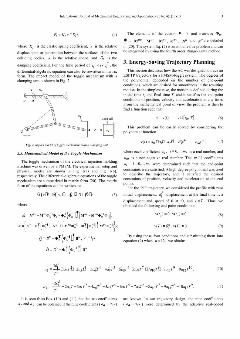
2.2. Impact Model
In this section, we consider the motion in a given stroke of
the toggle mechanism undergoing impact when two objects
collide over a very short period of time. The continuous force
model approach [19] employs a logical spring-damper
element to estimate the impact force between the two masses
of the mechatronic system as,
Moving plane
Timing belt
Toggle mechanism
Linear scale Frame
Load cell
Close head
Ball screw
PMSM Toggle mechanism
Guide rod
Guide rod
Moving plane
Timing belt
Toggle mechanism
Linear scale Frame
Load cell
Close head
Ball screw
PMSM Toggle mechanism
Guide rod
Guide rod
BxδBm
iF
Impact free body diagram of B.
BxδBm
iF
Impact free body diagram of B.
International Journal of Mechanical Engineering and Applications 2016; 4(1): 1-10 3
,i llF K z D z= + ɺ (4)
where l
K is the elastic spring coefficient, z is the relative
displacement or penetration between the surfaces of the two
colliding bodies, zɺ is the relative speed, and lD is the
damping coefficient. For the time period of i it t t− +≤ ≤ , the
differential-algebraic equation can also be rewritten in matrix
form. The impact model of the toggle mechanism with a
clamping unit is shown in Fig. 2.
Fig. 2. Impact model of toggle mechanism with a clamping unit.
2.3. Mathematical Model of the Toggle Mechanism
The toggle mechanism of the electrical injection molding
machine was driven by a PMSM. The experimental setup and
physical model are shown in Fig. 1(a) and Fig. 1(b),
respectively. The differential-algebraic equations of the toggle
mechanism are summarized in matrix form [20]. The matrix
form of the equations can be written as:
( ) ( ) ( ) ( )ˆˆ ˆ ˆv v v v v v .M N , Q U D+ = +ɺɺ ɺ (5)
where
( )ˆ ,vv vu uv uuu v v u u vM M − − − = − − −
T1 T 1 1
M Φ Φ Φ Φ M M Φ Φ
( ) ( )ˆ ,v u vu uuv u u v u uN N γ− − − −
= − + −
T TT 1 1 T 1 1
Φ Φ N M Φ Φ Φ M Φ
( )ˆ ,v uv uQ B −= −
TT 1
Φ Φ B ,qU i=
( )1ˆ .T
v T uv uD D −= − Φ Φ D
The elements of the vectors ,u v and matrices ,uΦ
,vΦ ,uuM ,uv
M ,vuM ,vvM u
N and vN are detailed
in [20]. The system Eq. (5) is an initial value problem and can
be integrated by using the fourth order Runge-Kutta method.
3. Energy-Saving Trajectory Planning
This section discusses how the AC was designed to track an
ESPTP trajectory for a PMSM-toggle system. The degrees of
the polynomial depended on the number of end-point
conditions, which are desired for smoothness in the resulting
motion. In the simplest case, the motion is defined during the
initial time t0 and final time T, and it satisfies the end-point
conditions of position, velocity and acceleration at any time.
From the mathematical point of view, the problem is then to
find a function such that
[ ]0v v( ), , .t t t T= ∈ (6)
This problem can be easily solved by considering the
polynomial function
2 30 1 2 3v( ) ... ,m
mt a a t a t a t a t= + + + + + (7)
where each coefficient ,ia 0,..., ,i m= is a real number, and
ma is a non-negative real number. The 1m + coefficients
,ia 0,..., ,i m= were determined such that the end-point
constraints were satisfied. A high-degree polynomial was used
to describe the trajectory, and it satisfied the desired
constraints of position, velocity and acceleration at the end
points.
For the PTP trajectory, we considered the profile with zero
initial displacement, 1hθ displacement at the final time T, a
displacement and speed of 0 at t0, and t T= . Thus, we
obtained the following end-point conditions:
0 0v( ) 0, v( ) 0,t t= =ɺ (8)
1v( ) , v( ) 0.hT Tθ= =ɺ (9)
By using these four conditions and substituting them into
equation (9) when 12,n = we obtain:
2 3 4 5 6 7 8 9 1012 4 5 6 7 8 9 10 11 122
32 3 4 5 6 7 8 9 ,
h
a a T a T a T a T a T a T a T a T a TT
θ= + + + + + + + + + (10)
2 3 4 5 6 7 8 913 4 5 6 7 8 9 10 11 123
22 3 4 5 6 7 8 9 10 .
h
a a T a T a T a T a T a T a T a T a TT
θ−= − − − − − − − − − (11)
It is seen from Eqs. (10) and (11) that the two coefficients
2 3 and a a can be obtained if the nine coefficients ( 4 12~a a )
are known. In our trajectory design, the nine coefficients
( 4 12~a a ) were determined by the adaptive real-coded

4 Yi-Lung Hsu et al.: Adaptive Tracking Control of a PMSM-Toggle System with a Clamping Effect
genetic algorithm (ARGA) method with an energy-saving
fitness function.
The PMSM is considered thermodynamically as an energy
converter. It takes electrical energy from a controlled input
and then outputs it as mechanical work to drive the toggle
mechanism system with a clamping unit. The input absolute
electrical energy (IAEE) to the system is defined as
0
T
i q qE i v dt= ∫ (12)
where qi is the electric current and qv is the voltage
command.
4. Adaptive Real-Coded Genetic
Algorithm
It is important that crossover probability and mutation
probability are set correctly for the genetic algorithms;
improper settings will cause algorithms to only find local
optimums and will also cause premature convergence.
Therefore, an efficient method that allows for fast settings is
essential. To resolve this, a mechanism to adjust the crossover
probability and mutation probability according to the
algorithmic performance was considered. In this study, the
adaptive real-coded genetic algorithm for polynomial
coefficient identification of the ESPTP trajectory of the
PMSM-toggle system was employed.
In equations (10) and (11), there were nine unknown
coefficients 4 12~a a to be determined by the ARGA. First,
we defined the decision vector as
[ ]4 5 6 7 8 9 10 11 12, , , , , , , ,a a a a a a a a a=z . (13)
The procedure carried out for the ARGA is shown in Fig. 3.
In this study, the procedure was reproduced through roulette
wheel selection, while the crossover and uniform mutation
were carried out through the methods described in [21].
Fig. 3. Flow chart for carrying out adaptive real-coded genetic algorithm.
4.1. Fitness Function
How the fitness function is defined is the key to the genetic
algorithm since the fitness function is a figure of merit and could
be computed by using any domain knowledge. In the proposed
ESPTP trajectory planning problem, the researchers defined the
input energy function as the fitness function ( )f z as
( )1
( ),m
ii
f E
==∑z z (14)
where m is the total number of samples and ( )iE z is the
input energy of the thi sampling time.
( ) 1
( )i
fE
=zz
( )
T
i q q
0
E i v dt= ∫z
1) Define polynomial function.
2
0 1 2( ) ...... n
nt a a t a t a t= + + + +v
2) Set motion constraints.
3) Define energy-saving
fitness function.
Start
4) Generate initial population
and evaluate fitness value.
R2) Create new population
(alternation of generation).
R1) Evaluate fitness value
for offspring chromosomes.
5) Reproduction
9) Satisfies
maximum generation?
11) End
10) Generate table.
Monotonically
Increasing function
1( ) ( )v vi it t +≤
No
Yes
Yes
No
8)
Adaptive probabilities rule.
6) Crossover
7) Mutation
( ) 1
( )i
fE
=zz
( )
T
i q q
0
E i v dt= ∫z
1) Define polynomial function.
2
0 1 2( ) ...... n
nt a a t a t a t= + + + +v
2) Set motion constraints.
3) Define energy-saving
fitness function.
3) Define energy-saving
fitness function.
Start
4) Generate initial population
and evaluate fitness value.
R2) Create new population
(alternation of generation).
R1) Evaluate fitness value
for offspring chromosomes.
5) Reproduction
9) Satisfies
maximum generation?
11) End
10) Generate table.
Monotonically
Increasing function
1( ) ( )v vi it t +≤
No
Yes
Yes
No
8)
Adaptive probabilities rule.
6) Crossover6) Crossover
7) Mutation7) Mutation

International Journal of Mechanical Engineering and Applications 2016; 4(1): 1-10 5
4.2. Adaptive Probability Law
To reduce premature convergence and improve the
convergence rate of the traditional real-coded genetic
algorithm (TRGA), the adaptive probabilities of crossover and
mutation were used in the ARGA. “Crossover” is the breeding
of two parents to produce a single offspring which possesses
features of both parents and thus may turn out better or worse
than either parent according to the objective function. The
primary purpose of mutation is to introduce variation, help
bring back certain essential genetic traits, and avoid premature
convergence of the entire feasible space caused by certain
super chromosomes.
To reduce premature convergence and improve the
convergence rate of the TRGA, the adaptive probabilities rule
[21] of crossover and mutation were used in the ARGA. The
probabilities of crossover cΓ and mutation mΓ are
respectively given as follows:
( )( ) ( )
avg'
max min avg
1 ,
c
cc
c c
F
F F F
δ
δδα
Γ = Γ × + − +
(15)
( )( ) ( )
avg'
max min avg
1 ,
c
cc
m m
F
F F F
δ
δδβ
Γ = Γ × + − +
(16)
where max ,F minF and avgF are the maximum, minimum
and average individual fitness values of (14), respectively,
'cΓ and '
mΓ are the crossover and mutation probabilities,
respectively, and , , and cα β δ are coefficient factors. In this
study, the values 0.24, 0.17,α β= = and 0.22cδ = [21]
were used. From Eqs. (15) and (16), it can be seen that the
adaptive cΓ and mΓ vary with fitness functions. cΓ and
mΓ increase when the population tends to get stuck at a local
optimum (when attraction basins are found around locally
optimal points) and decrease when the population is scattered
in the solution space.
4.3. Increasing Function
For the sake of tracking the motion profile of the
mechatronic system, the trajectory displacement needs to be
designed as a monotonically increasing function from the start
point to the end point. In this study, ( )v ,t 0 t T≤ ≤ was
assumed as the monotonically increasing function:
1v( ) v( ),i it t +≤ 1,i it t +≤ (17)
where the subscript i represents the thi
sampling time. This
constraint of the monotonically increasing function had to be
included in the procedure of the ARGA as shown in Fig. 3.
5. Adaptive Control Design
In this study, the researchers used the law of AC to
describe what happens when two objects collide. “To adapt”
means to change a behavior to conform to new circumstances.
The AC law can control the two objects and balance the
speed. The AC system is shown in Fig. 4, where *Bx and
Bx are the slider command position and slider position of the
PMSM-toggle system, respectively. The slider position Bx
is the desired control objective and can be manipulated by the
relation 1 12 cosBx r θ= , where the angle 1 vθ = is the
experimentally measured state as found by use of a linear
encoder system.
Fig. 4. Block diagram of the AC system.
In order to design an AC, the researchers rewrote Eq. (5) as
a second-order nonlinear equation:
( ) ( ) ( ) ( )( ) v; v v; ,u t f t t G t d t= + −ɺɺ (18)
where
( ) 1ˆ ˆv; ,f t Q M−= ( ) 1ˆ ˆv; ,G t Q N−= ( ) 1ˆ ˆ ,d t Q D−=
and ( )u t is the control input voltage. It was assumed that the
exact mass of slider B and the exact impact force iF could
not be known. With these uncertainties, the first step in
designing the AC was to select a Lyapunov function, which is
a function used for tracking error and parameter error. An
inertia-related Lyapunov function containing a quadratic form
of a linear combination of position- and speed-error states was
chosen as follows [15]:
11 1(v; ) ,
2 2
T TV s f t s φ φ−= + Γɶ ɶ (19)
where
*, v v ,es e e eλ= + = −ɺ
1
2
0,
0
γγ
ϒ =
[ ]ˆ ˆ ˆˆ, , .
TTB i B im F m Fφ φ φ φ φ = − = =
ɶ
and in which eλ , 1γ and 2γ are positive scalar constants.
The auxiliary signal s may be considered as a filtered
tracking error.
Differentiating Eq. (19) with respect to time gives

6 Yi-Lung Hsu et al.: Adaptive Tracking Control of a PMSM-Toggle System with a Clamping Effect
1 1 11 1ˆ ˆˆ ˆ(v; ) ,2 2
T T T TV s f t s s Q Ms s Q Ms φ φ− − −= + + + ϒɺ ɺ ɺɶ ɶɺ ɺ (20)
and by multiplying the variable sɺ with Eq. (20), we obtain
*1 1(v; ) (v; )( ) ( ) ( ) 2 sin ,e B Bf t s f t e x x A B r uλ φ θ= − + = • + • −ɺ ɺ ɺɺ ɺɺ (21)
where ( )A • and ( )B • are described in reference [15].
Substituting Eq. (21) into Eq. (20) gives
[ ]
[ ]
1 1 11 1
11 1
1 1ˆ ˆˆ ˆ( ) ( ) 2 sin2 2
( ) ( ) 2 sin ,
T T T T
T T
V s A B r u s Q Ms s Q Ms
s A B r u
φ θ φ φ
φ θ φ φ
− − −
−
= • + • − + + + ϒ
′ ′= • + • − + ϒ
ɺ ɺ ɺɶ ɶɺ
ɺɶ ɶ
(22)
where ( )A′ • and ( )B′ • are described in reference [15]. If
the control input is selected as
1 1
ˆ( ) ( ),
2 sin
VA B K su
r
φ
θ
′ ′• + • + = (23)
where VK is a positive constant, then Eq. (22) becomes
1( ) .
T T TVV s K s B sφ φ− ′= − + ϒ + •
ɺɶ ɶɺ (24)
By selecting the adaptive update rule as
ˆ ( ) ,TB sφ φ ′= − = −ϒ •ɺɺɶ (25)
and substituting it into Eq. (24), it then becomes
0.TVV s K s= − ≤ɺ (26)
Since Vɺ in Eq. (26) is negative semi-definite, then V in
Eq. (19) is upper-bounded. As V is upper-bounded and
(v; )f t is a positive-definite matrix, it can be said that s and
φɶ are bounded.
6. Numerical Simulations and
Experiment Results
6.1. Numerical Simulations
This section discusses how the researchers simulated the
ESPTP motion profile for the PMSM-toggle system. The
trajectory profile v( )t was chosen as a monotonically
increasing function. The input absolute electrical energy iE
was calculated by the fourth-order Runge-Kutta method via a
Windows supported MATLAB package with a sampling time
of 0.01sect∆ = and the time interval being from 0 to 1 sec.
In the numerical simulations, we adopted the parameters of the
PMSM-toggle system obtained as follows:
2 3 5
1 2 3 4 5 d
1.82 (kg), 1.61 (kg), 0.95 (kg), =8.86 (kg), = 5.58 (kg),
= 0.06 (m), = 0.032 (m), = 0.06 (m), = 0.068 (m), = 0.03 (m), = 0.01 (m),
0.068 (m), = 0.565 (Nm/A),
B C
t m
m m m m m
r r r r r l
h K J
= = =
= -5 2 -2
7
6.72 10 (Nms ), 1.21 10 (Nms/rad),
1.056 10 (kN/m), 970 (Ns/ m).
m
l l
B
K D
= × = ×
= × =
In the numerical simulations, the fitness value increased as the generation number increased, and almost all of the genes
4 5 12( , , , )a a a⋯ of the chromosome converged near the 30th generation for the twelfth-degree polynomial as shown in Figs.
5(a)-5(d). Figures 5(a) and 5(b) show the displacements and speeds. From the comparisons in Fig. 5(c), it is demonstrated that
the ARGA is more efficient in identifying polynomial coefficients than the TRGA. The energy used was less than 9×10⁻³ J. It is
thus concluded that the ARGA does not only find local optimums while preventing premature convergence, the fitness values
of the ARGA are greater than those of the TRGA.
(a) (b)
0.0 0.2 0.4 0.6 0.8 1.0
0.06
0.07
0.08
0.09
0.10
0.11
0.12
Dis
pla
cem
ent
(m
)
Time (s)
TRGA
ARGA
0.0 0.2 0.4 0.6 0.8 1.00.00
0.01
0.02
0.03
0.04
0.05
0.06
0.07
0.08
Time (s)
Sp
eed
(m
/s)
TRGA
ARGA

International Journal of Mechanical Engineering and Applications 2016; 4(1): 1-10 7
(c) (d)
Fig. 5. Comparisons of the TRGA and ARGA for 12th-degree polynomials in numerical simulations. (a) Displacement. (b) Speed. (c) IAEE. (d) Fitness values.
The comparisons of dynamic responses of the
PMSM-toggle system for trapezoidal, fourth-degree, and
twelfth-degree polynomials are shown in Figs. 7(a)-7(d). The
speeds are compared in Fig. 7(c). The displacement- and
speed-error comparisons with respect to the trapezoidal,
fourth-degree and twelfth-degree polynomials are shown in
Figs. 7(b) and 7(d). (The fourth-degree and twelfth-degree
polynomials were formulated based on ESPTP trajectories.)
The final identification of the polynomial coefficients a4 ~
a12, the values of the fitness function of the mechatronic
system, and the highest fitness value were found by using the
twelfth-degree polynomial. The total energy values are also
compared in Table 1, where the final values are about
3 38.320 10 J , 9.661 10 J, − −× × and 37.654 10 J.
−× The
lowest value is that of the twelfth-degree polynomial, and the
trapezoidal polynomial had a relative reduction of -8% in
input energy.
6.2. Experimental Setup
A photo of the PMSM-toggle system with a clamping unit
is shown in Fig. 1(a), and the experimental equipment used is
shown in Fig. 6. The control algorithm was implemented by
using a Celeron computer, and the control software used was
LabVIEW. The PMSM was driven by a Mitsubishi
HC-KFS13 series. The specifications were set as follows:
rated torque of 1.3 Nm, rated rotation speed of 3k rpm, rated
output of 0.1 kW, and rated current of 0.7 A. The servo-motor
was driven by a Mitsubishi MR-J2S-10A.
Fig. 6. Experimental equipment for the PMSM-toggle system with a clamping unit.
6.3. Experimentation
For the ESPTP trajectory processes of a PMSM-toggle
system, the control objective was to control the position of
slider B to move from the start-position of 0 m to the
end-position of 0.116 m with the clamping point at 0.1159 m.
The numerical simulations and experimental results of
0.0 0.2 0.4 0.6 0.8 1.00.000
0.002
0.004
0.006
0.008
Time (s)
En
erg
y (
J)
TRGA
ARGA8.320x 10-3 J
7.654 x 10⁻³ J
0.0 0.2 0.4 0.6 0.8 1.00.000
0.002
0.004
0.006
0.008
Time (s)
En
erg
y (
J)
TRGA
ARGA8.320x 10-3 J
7.654 x 10⁻³ J
119.5
118.9
5 10 15 20 25 30
102104106108110112114116118120122124
Generation
Fit
nes
s v
alu
es
TRGA
ARGA
0
119.5
118.9
5 10 15 20 25 30
102104106108110112114116118120122124
Generation
Fit
nes
s v
alu
es
TRGA
ARGA
0
8 Yi-Lung Hsu et al.: Adaptive Tracking Control of a PMSM-Toggle System with a Clamping Effect
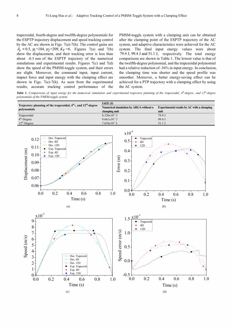
trapezoidal, fourth-degree and twelfth-degree polynomials for
the ESPTP trajectory displacement and speed tracking control
by the AC are shown in Figs. 7(a)-7(h). The control gains are
1 20.5, =104, =209, =6.e VKλ γ γ= Figures 7(a) and 7(b)
show the displacement, and their tracking error is less than
about -0.5 mm of the ESPTP trajectory of the numerical
simulations and experimental results. Figures 7(c) and 7(d)
show the speed of the PMSM-toggle system, and their errors
are slight. Moreover, the command input, input current,
impact force and input energy with the clamping effect are
shown in Figs. 7(e)-7(h). As seen from the experimental
results, accurate tracking control performance of the
PMSM-toggle system with a clamping unit can be obtained
after the clamping point of the ESPTP trajectory of the AC
system, and adaptive characteristics were achieved for the AC
system. The final input energy values were about
79.9 J, 99.4 J and 51.1 J, respectively. The total energy
comparisons are shown in Table 1. The lowest value is that of
the twelfth-degree polynomial, and the trapezoidal polynomial
had a relative reduction of -36% in input energy. In conclusion,
the clamping time was shorter and the speed profile was
smoother. Moreover, a better energy-saving effect can be
achieved for a PTP trajectory with a clamping effect by using
the AC system.
Table 1. Comparisons of input energy for the numerical simulation and experimental trajectory planning of the trapezoidal, 4th-degree, and 12th-degree
polynomials of the PMSM-toggle system.
Trajectory planning of the trapezoidal, 4th-, and 12th-degree
polynomials
IAEE (J)
Numerical simulation by ARGA without a
clamping unit
Experimental results by AC with a clamping
unit
Trapezoidal 8.320×10⁻³ J 79.9 J
4th-Degree 9.661×10⁻³ J 99.4 J
12th-Degree 7.654×10⁻³ J. 51.1 J
(a) (b)
(c) (d)
0.0 0.2 0.4 0.6 0.8 1.0
0.06
0.07
0.08
0.09
0.10
0.11
0.12
Time (s)
Dis
pla
cem
ent
(m)
Des. Trapezoid
Des. 4D
Des. 12D
Exp. Trapezoid
Exp. 4D
Exp. 12D
0.0 0.2 0.4 0.6 0.8 1.00.0
0.1
0.2
0.3
0.4
0.5
Err
or
(m)
Time (s)
Trapezoid
4D
12D
x10-4
0.0 0.2 0.4 0.6 0.8 1.00
1
2
3
4
5
6
7
8
9x10
-3
Time (s)
Sp
eed
(m
/s)
Des. Trapezoid
Des. 4D
Des. 12D
Exp. Trapezoid
Exp. 4D
Exp. 12D
0.0 0.2 0.4 0.6 0.8 1.0-0.5
0.0
0.5
1.0
1.5
Time (s)
Sp
eed
err
or
(m/s
)
Trapezoid
4D
12D
x10-3

International Journal of Mechanical Engineering and Applications 2016; 4(1): 1-10 9
(e) (f)
(g) (h)
Fig. 7. Comparisons of numerical simulations and experimental results for trapezoidal, fourth-degree and twelfth-degree polynomials by AC. (a)
Displacement tracking. (b) Displacement tracking error. (c) Speed tracking. (d) Speed tracking error. (e) Input voltage. (f) Input current. (g) Impact force. (h)
IAEE.
7. Conclusion
A mathematical model was put into use for a PMSM-toggle
system with a clamping unit, and the ESPTP trajectory for the
mechatronic system was successfully planned by the adaptive
real-coded genetic algorithm method described in this paper.
The proposed AC was established by the Lyapunov stability
theory for a mechatronic system with uncertainties and the
impact force not being exactly known. The proposed
methodology described in this paper was applied to a
mechatronic system with a clamping unit. The mechatronic
system required the design of an ESPTP trajectory which can
be interpreted by any continuous function and which has
different motion constraints at the start and end points. The
results demonstrate that the adaptive control performance in
the PTP trajectory with a clamping effect is successful for a
mechatronic system.
Acknowledgement
The financial support from the Ministry of Science and
Technology of the Republic of China with contract number
MOST 103-2221-E-327 -009 -MY3 is gratefully
acknowledged.
References
[1] Pu, J., Weston, R. H. and Moore, P. R., Digital Motion Control and Profile Planning for Pneumatic Servos, ASME J. of DSMC, Vol. 114, No. 4, pp. 634-640, 1992.
[2] Astrom, K. J. and Wittenmark, B., Adaptive Control, Addison-Wesley, MA, 1994.
[3] Slotine, J. J. E. and Li, W., Composite Adaptive Control of Robot Manipulators, Automatica, Vol. 25, No. 4, pp. 509-519, 1989.
[4] Biagiotti, L. and Melchiorri, C., Trajectory Planning for Automatic Machines and Robots, Springer-Verlag, 2008.
[5] Mohamed, Y. A. -R. I., Design and Implementation of a Robust Current-Control Scheme for a PMSM Vector Drive With a Simple Adaptive Disturbance Observer, IEEE Trans. on Industrial Electronics, Vol. 54, No. 4, pp. 1981-1988, 2007.
[6] Kim, K. H., Model Reference Adaptive Control-Based Adaptive Current Control Scheme of a PM Synchronous Motor with an Improved Servo Performance, IET Electric Power Applications, Vol. 3, No. 1, pp. 8-18, 2009.
0.95 0.96 0.97 0.98 0.99 1.000.0
0.5
1.0
1.5
2.0
2.5
3.0
0.0 0.2 0.4 0.6 0.8 1.0
0.00
0.01
0.02
0.03
0.04
0.05v q
(V
)
Time (s)
Trapezoid
4D
12D
0.95 0.96 0.97 0.98 0.99 1.000.0
0.5
1.0
1.5
2.0
2.5
3.0
0.0 0.2 0.4 0.6 0.8 1.0
0.00
0.01
0.02
0.03
0.04
0.05v q
(V
)
Time (s)
Trapezoid
4D
12D
0.0 0.2 0.4 0.6 0.8 1.0-0.005
0.000
0.005
0.010
0.015
0.020
0.025
0.030
Time (s)
i q (
A)
Trapezoid
4D
12D
0.95 0.96 0.97 0.98 0.99 1.000.0
0.5
1.0
1.5
2.0
2.5
0.0 0.2 0.4 0.6 0.8 1.0-0.005
0.000
0.005
0.010
0.015
0.020
0.025
0.030
Time (s)
i q (
A)
Trapezoid
4D
12D
0.95 0.96 0.97 0.98 0.99 1.000.0
0.5
1.0
1.5
2.0
2.5
0.11580 0.11585 0.11590 0.11595 0.116000
300
600
900
1200
1500 Trapezoid
4D
12D
F
i (k
N)
Position (m)
Clamping point
End point
0.11580 0.11585 0.11590 0.11595 0.116000
300
600
900
1200
1500 Trapezoid
4D
12D
F
i (k
N)
Position (m)
Clamping point
End point
0.95 0.96 0.97 0.98 0.99 1.00
0
20
40
60
80
100
0.0 0.2 0.4 0.6 0.8 1.00.000
0.005
0.010
0.015
0.020
0.025
Time (s)
En
erg
y (
J)
Trapezoid
4D
12D
0.95 0.96 0.97 0.98 0.99 1.00
0
20
40
60
80
100
0.0 0.2 0.4 0.6 0.8 1.00.000
0.005
0.010
0.015
0.020
0.025
Time (s)
En
erg
y (
J)
Trapezoid
4D
12D

10 Yi-Lung Hsu et al.: Adaptive Tracking Control of a PMSM-Toggle System with a Clamping Effect
[7] Shihua, L. and Zhigang, L., Adaptive Speed Control for Permanent-Magnet Synchronous Motor System with Variations of Load Inertia, IEEE Trans. on Industrial Electronics, Vol. 56, No. 8, pp. 3050-3059, 2009.
[8] Lee, D. H., Lee, J. H. and Ahn, J. W., Mechanical Vibration Reduction Control of Two-Mass Permanent Magnet Synchronous Motor Using Adaptive Notch Filter with Fast Fourier Transform Analysis, IET Electric Power Applications, Vol. 6, No. 7, pp. 455-461, 2012.
[9] Cho, S. H. and Helduser, S., Robust Motion Control of a Clamp-Cylinder for Energy-Saving Injection Moulding Machines, Journal of Mechanical Science and Technology, Vol. 22, No. 12, pp. 2445-2453, 2008.
[10] Kendra, S. J., Basila, M. R. and Cinar, A., Intelligent Process Control with Supervisory Knowledge-Based Systems, IEEE Control Systems, Vol. 14, No. 3, pp. 37-47, 1994.
[11] Wai, R. J., Adaptive Sliding-Mode Control for Induction Servomotor Drive, IEE Proceedings on Electric Power Applications, Vol. 147, No. 6, pp. 553-562, 2000.
[12] Chen, K. Y., Huang, M. S. and Fung, R. F., Adaptive Minimum-Energy Tracking Control for the Mechatronic Elevator System, IEEE Trans. on Control Systems Technology, Vol. PP, No. 99, 2013.
[13] Fung, R. F. and Chen, K. W., Dynamic Analysis and Vibration Control of a Flexible Slider-Crank Mechanism Using PM Synchronous Servo Motor Drive, Journal of Sound and Vibration, Vol. 214, No. 4, pp. 605-637, 1998.
[14] Lin, F. J., Fung, R. F. and Wai, R. J., Comparison of Sliding-Mode and Fuzzy Neural Network Control for Motor-Toggle Servomechanism, IEEE/ASME Transactions on Mechatronics, Vol. 3, No. 4, pp. 302-318, 1998.
[15] Chuang, C. W., Huang, M. S., Chen, K. Y. and Fung, R. F., Adaptive Vision-Based Control of a Motor-Toggle Mechanism: Simulations and Experiments, Journal of Sound and Vibration, Vol. 312, No. 4-5, pp. 848-861, 2008.
[16] Fung, R. F. and Chang, C. F., Force/Motion Sliding Mode Control of Three Typical Mechanisms, Asian Journal of Control, Vol. 11, No. 2, pp. 196-210, 2009.
[17] Cerman, O. and Hušek, P., Adaptive Fuzzy Sliding Mode Control for Electro-Hydraulic Servo Mechanism, Expert Systems with Applications, Vol. 39, No. 11, pp. 10269-10277, 2012.
[18] Cho, S. H. and Fung, R. F., Virtual Design of a Motor-Toggle Servomechanism with Sliding Mode-Combined PID Control, Proceedings of the Institution of Mechanical Engineers, Part C: Journal of Mechanical Engineering Science, pp. 1-10, 2014. DOI: 10.1177/0954406214531944
[19] Khulief, Y. A. and Shabana, A. A., A Continuous Force Model for the Impact Analysis of Flexible Multibody Systems, Mechanism and Machine Theory, Vol. 22, No. 3, pp. 213-224, 1987.
[20] Hsu, Y. L., Huang, M. S. and Fung, R. F., Convergent Analysis of an Energy-Saving Trajectory for a Motor-Toggle System, Journal of Vibration Engineering and Technologies, Vol. 3, No. 1, pp. 95-112, 2015.
[21] Du, Y., Fang, J. and Miao, C., Frequency-Domain System Identification of an Unmanned Helicopter Based on an Adaptive Genetic Algorithm, IEEE Trans. on Industrial Electronics, Vol. 61, No. 2, pp. 870-881, 2014.